

Page 1

ALS
204/206
256
USER MANUAL
Label Dispenser
Edition 7 04/2010
Page 2

Page 3

3
CONTENTS
ALS
20x
256
GB
1 Please note
1.1 General notes
1.1.1 Validity and binding effect of this manual . . . . 5
Contents . . . . . . . . . . . . . . . . . . . . . . . . . . . . . . .5
Technical status . . . . . . . . . . . . . . . . . . . . . . . . .5
Copyright. . . . . . . . . . . . . . . . . . . . . . . . . . . . . . .5
Manufacturer. . . . . . . . . . . . . . . . . . . . . . . . . . . .5
1.1.2 Illustrations and descriptions. . . . . . . . . . . . . . 6
Signs and symbols . . . . . . . . . . . . . . . . . . . . . . . 6
Dangers and risk notes . . . . . . . . . . . . . . . . . . . .6
Figures . . . . . . . . . . . . . . . . . . . . . . . . . . . . . . . .6
Button symbols . . . . . . . . . . . . . . . . . . . . . . . . . .6
Parameters . . . . . . . . . . . . . . . . . . . . . . . . . . . . .6
Supplementary information . . . . . . . . . . . . . . . . .6
1.2 Safety instructions
1.2.1 Information and qualifications. . . . . . . . . . . . . 7
Follow the instructions. . . . . . . . . . . . . . . . . . . . .7
Keep the product information at hand. . . . . . . . . 7
Ensure the required qualifications are met . . . . .7
1.2.2 Operational safety of the unit . . . . . . . . . . . . . 8
Proper usage. . . . . . . . . . . . . . . . . . . . . . . . . . . .8
Protection against injuries by electrical current. .8
Protection against injuries by mechanical action.9
Protection against injuries by chemicals . . . . . . .9
1.2.3 Before beginning production. . . . . . . . . . . . . 10
Due diligence of the operating company and the
service technician . . . . . . . . . . . . . . . . . . . . . . .10
Due diligence of the user. . . . . . . . . . . . . . . . . .10
1.2.4 Safety notes on the unit . . . . . . . . . . . . . . . . 11
2 Product description
2.1 Overview
2.1.1 Components . . . . . . . . . . . . . . . . . . . . . . . . . 12
2.1.2 Control panel. . . . . . . . . . . . . . . . . . . . . . . . . 14
Operating LED. . . . . . . . . . . . . . . . . . . . . . . . . .14
Error LED . . . . . . . . . . . . . . . . . . . . . . . . . . . . .14
LCD display. . . . . . . . . . . . . . . . . . . . . . . . . . . .14
Buttons . . . . . . . . . . . . . . . . . . . . . . . . . . . . . . .14
Language . . . . . . . . . . . . . . . . . . . . . . . . . . . . .14
2.1.3 Connection arrangement . . . . . . . . . . . . . . . 15
Connections on the back of the device . . . . . . .15
Sensor connections. . . . . . . . . . . . . . . . . . . . . .16
2.1.4 Mode of operation. . . . . . . . . . . . . . . . . . . . . 17
2.1.5 Technical specifications. . . . . . . . . . . . . . . . 18
Characteristics. . . . . . . . . . . . . . . . . . . . . . . . . .18
Labels . . . . . . . . . . . . . . . . . . . . . . . . . . . . . . . .18
Label sensor . . . . . . . . . . . . . . . . . . . . . . . . . . .18
Power supply. . . . . . . . . . . . . . . . . . . . . . . . . . .18
Electronics. . . . . . . . . . . . . . . . . . . . . . . . . . . . .19
Interfaces. . . . . . . . . . . . . . . . . . . . . . . . . . . . . .19
Internal Interfaces . . . . . . . . . . . . . . . . . . . . . . .19
Status messages, test functions,
product profiles . . . . . . . . . . . . . . . . . . . . . . . . .19
Dimensions . . . . . . . . . . . . . . . . . . . . . . . . . . . .20
Environmental conditions . . . . . . . . . . . . . . . . .20
Integration . . . . . . . . . . . . . . . . . . . . . . . . . . . . .20
Certificates. . . . . . . . . . . . . . . . . . . . . . . . . . . . .20
2.1.6 Design models . . . . . . . . . . . . . . . . . . . . . . . 21
Right-handed version . . . . . . . . . . . . . . . . . . . .21
Left-handed version. . . . . . . . . . . . . . . . . . . . . .21
2.2 Options
External control panel . . . . . . . . . . . . . . . . . . . .22
Fixed dispensing edge. . . . . . . . . . . . . . . . . . . .22
Swivelling dispensing edge . . . . . . . . . . . . . . . .22
Spring-loaded dispensing edge. . . . . . . . . . . . .22
Pneumatic dispensing edge . . . . . . . . . . . . . . .23
V-shape dispensing edge . . . . . . . . . . . . . . . . .23
Adjustable dispensing edge holder . . . . . . . . . .23
Outer Diameter control sensor . . . . . . . . . . . . .24
Dust/Splash guard. . . . . . . . . . . . . . . . . . . . . . .24
Additional material guide disk . . . . . . . . . . . . . .24
Capacitive label sensor . . . . . . . . . . . . . . . . . . .25
Printer . . . . . . . . . . . . . . . . . . . . . . . . . . . . . . . .25
Applicator. . . . . . . . . . . . . . . . . . . . . . . . . . . . . .25
Applicator interface . . . . . . . . . . . . . . . . . . . . . .25
Narrow label spring kit. . . . . . . . . . . . . . . . . . . .25
2.3 Operating modes
2.3.1 Dispensing mode . . . . . . . . . . . . . . . . . . . . . 26
Stopping/Continuing the dispensing. . . . . . . . .26
Changing the counter reading . . . . . . . . . . . . . .26
Starting the unit in configuration mode . . . . . . .26
Counting labels backwards . . . . . . . . . . . . . . . .26
Online settings. . . . . . . . . . . . . . . . . . . . . . . . . .27
2.3.2 Configuration mode . . . . . . . . . . . . . . . . . . . 28
Function of the double-arrow button . . . . . . . . .28
Menus . . . . . . . . . . . . . . . . . . . . . . . . . . . . . . . .28
Functions. . . . . . . . . . . . . . . . . . . . . . . . . . . . . .29
Page 4

4
CONTENTS
ALS
20x
256
GB
2.4 Function descriptions
2.4.1 Overview of functions . . . . . . . . . . . . . . . . . . 30
2.4.2 Notes. . . . . . . . . . . . . . . . . . . . . . . . . . . . . . . 32
Function descriptions . . . . . . . . . . . . . . . . . . . .32
Quick setting . . . . . . . . . . . . . . . . . . . . . . . . . . .32
2.4.3 LABEL SETUP menu . . . . . . . . . . . . . . . . . . 32
2.4.4 MACHINE SETUP menu . . . . . . . . . . . . . . . 33
3 Before operation
3.1 Electrical connections
3.1.1 Power supply connection . . . . . . . . . . . . . . . 34
Checking the power supply setting . . . . . . . . . .35
Connecting the power cable.. . . . . . . . . . . . . . .35
3.1.2 Connecting sensors . . . . . . . . . . . . . . . . . . . 36
3.2 Inserting label material
3.2.1 Prerequisites. . . . . . . . . . . . . . . . . . . . . . . . . 37
3.2.2 Inserting a label roll. . . . . . . . . . . . . . . . . . . . 38
Removing spent backing paper. . . . . . . . . . . . .38
Removing glue residue . . . . . . . . . . . . . . . . . . .38
Inserting a new label roll . . . . . . . . . . . . . . . . . .38
3.2.3 Threading the label roll . . . . . . . . . . . . . . . . . 39
Threading guide . . . . . . . . . . . . . . . . . . . . . . . .39
Threading the label roll at the dispensing edge.40
Threading the label roll onto the drive roller . . .41
Fastening the label roll to the rewinder . . . . . . .41
3.3 Mechanical settings
3.3.1 Adjusting the unwinder’s core diameter . . . . 42
3.3.2 Positioning the pressure roller . . . . . . . . . . . 42
3.3.3 Positioning the label sensor . . . . . . . . . . . . . 43
3.3.4 Setting the dancer arm restoring force . . . . . 43
4 Operation
4.1 Start-up and shutdown
4.1.1 Turning on the unit . . . . . . . . . . . . . . . . . . . . 44
4.1.2 Starting label dispensing. . . . . . . . . . . . . . . . 44
Dispensing with a product sensor . . . . . . . . . . .44
Dispensing without a product sensor . . . . . . . .44
4.1.3 Stopping/Continuing the dispensing process 44
4.2 Configuration and monitoring
4.2.1 Function menu settings . . . . . . . . . . . . . . . . 45
Label pitch. . . . . . . . . . . . . . . . . . . . . . . . . . . . .45
Label stop position. . . . . . . . . . . . . . . . . . . . . . .45
Dispensing speed . . . . . . . . . . . . . . . . . . . . . . .46
Suppressing start signals . . . . . . . . . . . . . . . . .46
Label position on the product . . . . . . . . . . . . . .47
4.2.2 Monitoring functions. . . . . . . . . . . . . . . . . . . 48
Material end / Roll diameter. . . . . . . . . . . . . . . .48
Missing labels . . . . . . . . . . . . . . . . . . . . . . . . . .49
Material tear. . . . . . . . . . . . . . . . . . . . . . . . . . . .49
4.3 Using product profiles
4.3.1 What are product profiles?. . . . . . . . . . . . . . 50
4.3.2 Loading a product profile . . . . . . . . . . . . . . . 50
4.3.3 Storing a product profile. . . . . . . . . . . . . . . . 50
Selecting the memory location . . . . . . . . . . . . .50
Entering profile names. . . . . . . . . . . . . . . . . . . .50
4.3.4 Deleting a product profile. . . . . . . . . . . . . . . 51
5 After operation
5.1 Maintenance and cleaning
5.1.1 Replacing fuses . . . . . . . . . . . . . . . . . . . . . . 52
5.1.2 Cleaning agents. . . . . . . . . . . . . . . . . . . . . . 53
5.1.3 Regular maintenance. . . . . . . . . . . . . . . . . . 54
Removing paper debris . . . . . . . . . . . . . . . . . . .54
Renewal of the dust filter liner (ALS256) . . . . .54
6 Operational failures
6.1 Status messages
6.1.1 Types of status messages . . . . . . . . . . . . . . 55
Error messages. . . . . . . . . . . . . . . . . . . . . . . . .55
Warnings . . . . . . . . . . . . . . . . . . . . . . . . . . . . . .55
6.1.2 List of warnings . . . . . . . . . . . . . . . . . . . . . . 55
6.1.3 List of error messages . . . . . . . . . . . . . . . . . 56
7 Appendix
7.1 EC declaration of conformity
Page 5

5
1PLEASE NOTE
1.1 GENERAL NOTES
ALS
20x
256
GB
1.1.1 Validity and binding effect of this manual
Contents
The present manual refers exclusively to the ALS204,
ALS206 and ALS256 label dispensers. It is written for
the purpose of ensuring professional usage and
calibration of the unit.
Prerequisites for the use and adjustment are the
professional installation and configuration of the unit.
For any technical questions you may have that are not
described in this manual, see:
£ The service manual of the label dispenser
or
£ Request a technician from one of our sales partners.
– Our sales representatives are available to assist
you, particularly with configuring the unit as well as
in the case of malfunctions.
Technical status
Technical state: 12/2009
Software versions: 1.34
Avery Dennison reserves the right:
– To make modifications to construction parts,
components and software, as well as to employ
comparable components in place of the parts
specified, in keeping with technical advances.
– To modify information in this document.
No commitment will be made to expand these
modifications to include any units delivered earlier.
Copyright
Avery Dennison holds all rights to this manual and its
appendices. Reproduction, reprinting or any other
types of duplication, even of portions of this manual,
may only be carried out with express written consent.
Third persons, in particular competitors, should not be
given access to the information in this manual.
Printed in Germany
Manufacturer
Avery Dennison Deutschland GmbH
Ohmstrasse 3
85386 Eching, Germany
Phone: +49-8165-925-0
Fax: +49-8165-925-231
http://www.machines.averydennison.com
1 PLEAS E NOTE
1.1 GENERAL NOTES
Page 6

6
1PLEASE NOTE
1.1 GENERAL NOTES
ALS
20x
256
GB
1.1.2 Illustrations and descriptions
Signs and symbols
Various information types are indicated in differ en t
ways within the document in order to simplify
readability and comprehension.
Sentences starting with an arrow are instructions and
guidelines.
£ Perform the instructions one after another in the
specified order.
The following information begins with a dash:
–Lists
– Mode descriptions
– Descriptions of prior steps
– Prerequisites for following actions
Dangers and risk notes
Important directions that you must absolutely observe
are particularly emphasized:
WARNING!
A warning refers to risks that can lead to
serious injury or death! The warning
contains safety measures to protect the
relevant persons.
£ Always follow the instructions.
CAUTION!
A caution indicates risks that can lead to
property damage or injuries to persons
(minor injuries). The caution note contains
instructions for preventing dama ge s .
£ Always follow the instructions.
Figures
Texts are accompanied by figures where necessary.
Figures are indicated using figure numbers in [square
brackets]. A capital letter after a figure number, for
example [12A], refers to a specific section of the figure.
Generally, the label dispenser shown is a right-handed
version. The left-handed version is only shown where it
is necessary to differentiate between the two.
Button symbols
– The buttons of the control panel are depicted as
symbols.
– The symbols are depicted with a ‘+’ (PLUS SIGN)
between them if more than one button is to be
pressed. +
Parameters
Parameters are displayed in grey in the text with the
following structure, MENU NAME > Function name.
Supplementary information
The expert symbol indicates actions that are
only to be performed by qualified and specially
trained personnel.
The information symbol indicates notes and
recommendations, as well as additional
information.
Equipment:
– Equipment, for example lubricants or
cleaning agents
Page 7

7
1PLEASE NOTE
1.2 SAFETY INSTRUCTIONS
ALS
20x
256
GB
1.2.1 Information and qualifications
Follow the instructions
WARNING!
Safe and efficient operation of the label
dispenser can only be guaranteed if you
observe all necessary information.
Product liability and warranty claims can
only be asserted if the unit was operated in
accordance with the directions in the
manual.
£ Before operating the unit, read the
operating instructions and all other notes
carefully.
£ Observe the additional safety and
warning notes on the label dispenser.
£ Only permit competent people to operate
and configure the label dispenser.
Keep the product information at hand
With respect to this manual:
£ It should be kept at the location where the
unit is installed and be available to the
operator.
£ It should always be legible.
£ If the unit is sold, the manual should be made
available to the new owner.
£ The safety and warning notes affixed to the
unit itself must be kept clean and legible.
Missing or damaged signs must be replaced.
Ensure the required qualifications are met
£ Ensure that only trained and authorized personnel
operate, configure and service the unit.
£ Only allow qualified and well-trained expert
personnel or service technicians to perform
configurations.
£ The responsibilities with regard to operation,
configuration and maintenance should be cl ea rly
defined and consistently maintained.
£ In addition, personnel should also be instructed on
a regular basis in matters of occupational safety and
environmental protection.
Qualification for operation
The instruction of personnel using the unit must ensure
that:
– The operating perso nnel can use the unit on their
own and safely.
– The operating personnel can remedy small
operational disruptions on their own.
£ At least two people must be instructed in the unit’s
usage.
£ Enough label material must be provided for testing
and instructional purposes.
Qualifications for configuring
The configuration of the controls requires
qualified expertise:
– Personnel configuring the unit must be
acquainted with the functionality of the label
dispenser.
– Personnel configuring the unit must be
acquainted with the modes of operation
within the facility in which the label dispenser
is integrated.
– The personnel configuring the unit must be
able to use the additional menus properly
and appropriately for specific project
requirements.
1.2 SAFETY INSTRUCTIONS
Page 8

8
1PLEASE NOTE
1.2 SAFETY INSTRUCTIONS
ALS
20x
256
GB
1.2.2 Operational safety of the unit
Proper usage
The label dispenser is a fully automatic unit for
attaching self-adhesive labels to products or
packaging. The company operating the unit must install
it with suitable equipment to protect operating
personnel from danger; for example, the danger of the
hands or fingers being crushed by reaching in between
the product and the dispensing edge.
WARNING!
Improper usage of the unit can cause
accidents, property damage and production
downtime!
£ Only use the unit in accordance with the
instructions specified in this manual.
£ Do not oper at e th e u ni t wit h ou t the
required safeguards.
£ Only configure the unit in accordance
with this manual and with the required
care.
£ Only use original accessories.
£ Do not make any modifications or
alterations to the unit.
£ Repairs to the device may only be
performed by authorised specialists who
are aware of the risks involved.
Protection against injuries by electrical
current
WARNING!
The machine operates using mains voltage!
Touching live electrical parts may exp ose
you to hazardous electrical currents and
may lead to burns.
£ Only operate the unit once the housing
has been reassembled properly.
£ The machine may only be connected by
authorised specialists, who are aware of
the risks involved.
£ Before cleaning, switch off the unit and
remove the power cable from the socket.
£ Only link the unit to devices that fulfil the
SELV (safety extra-low voltage) circuit
requirements specified in EN60950.
£ Make sure that the power switch at the
machine is accessible.
£ In case of emergency, switch off the
device.
WARNING
The unit is not protected against splashing
water in its standard model.
£ Keep the unit dry.
£ If liquids have penetrated the unit, switch
it off and disconnect or unplug the power
cable immediately. Inform a service
technician.
CAUTION
A too high or low supply voltage can damage
the unit.
£ Only operate the device using the system
voltage indicated on the nameplate.
£ Ensure that the mains voltage set on the
unit is the same voltage as that provided
by the electricity supplier.
Page 9

9
1PLEASE NOTE
1.2 SAFETY INSTRUCTIONS
ALS
20x
256
GB
Protection against injuries by mechanical
action
WARNING!
Risk of injury due to moving and rapidly
rotating parts!
– Long hair, loose jewellery, long slee ves,
and so on are not permissible when using
the unit.
£ Sufficient protective clothing must be
worn.
£ Keep moving parts free from
obstructions even when the unit is not
switched on, if there is a chance the
machine might be turned on.
£ Switch off the machine before making
any mechanical settings.
£ Do not wear ties, loose clothing,
jewellery, wrist watches or similar items
on your person when near the operating
unit.
WARNING!
There is a risk that you may get your fing ers
or hands crushed on the dispensing edge by
products on the conveyor belt!
£ Never reach between the product and the
dispensing edge while the unit i s in
operation or ready for operation.
£ Never reach behind the safety guard or
remove it while the unit is in operation.
Protection against injuries by chemicals
CAUTION!
Operating materials such as cleaning agents
or the solvents in glues can be damaging to
health.
£ Always follow the instructions, use and
safety regulations specified by the
manufacturer!
Page 10

10
1PLEASE NOTE
1.2 SAFETY INSTRUCTIONS
ALS
20x
256
GB
1.2.3 Before beginning production
Due diligence of the operating company
and the service technician
£ Ensure that the following prerequisites are fulfilled in
accordance with the service instructions:
– The machine is installed properly and configured in
accordance with the guidelines.
– All required safety mechanisms have been installed.
– The unit has performed at least one successful test
run.
– The unit is connected to the power supply.
£ The users have the required personal protective
equipment, for example, a hairnet. Ensure that the
protective equipment is utilised correctly.
Due diligence of the user
£ Check that the safety installations are working
properly.
£ Inspect the machinery for any visible damage.
Report any ascertained defects immediately.
£ Use the required personal protective equipment
correctly, for example, wear a hairne t.
£ Remove any unnecessary materials and objects
from the operating area of the unit.
£ Ensure that only au th or ise d pe rs on s ar e with in th e
operating range of the machine.
£ Ensure that starting up the machine will not injure
anyone.
Page 11

11
1PLEASE NOTE
1.2 SAFETY INSTRUCTIONS
ALS
20x
256
GB
1.2.4 Safety notes on the unit
CAUTION!
Warning notes on the unit represent
important information for the personnel
using it.
£ Do not remove warning notes.
£ Replace any missing or illegible
warnings.
The ‘Pinch Point’ warning ] note warns you of the
danger posed by the machine’s rota ting parts; they can
trap items and draw them in.
The blue label ‘Read manual’ [2] demands that users
read the unit instructions.
[1] Left: ‘Pinch Point’ warning. Right: Position of the warning note on the ALS 20x. Item number of the label: A5346.
WARNING
!
Pinch point.
Keep hands clear
of rollers.
A5346
[2] Left: ‘Read manual’ notice. Right: Position of the notice on the ALS20x. Item number of the label: A5331.
Handbuch lesen!
Read the manual!
Lisez le manuel!
Lea el manual!
Legga il manuale!
Page 12

12
2PRODUCT DESCRIPTION
2.1 OVERVIEW
ALS
20x
256
GB
2.1.1 Components
[3] ALS204 Label Dispenser (right-handed version)
A
CD
E
F
H
I
J
K
L
M
N
O
B
G
ALS256
2 PRODUCT DESCRIPTION
2.1 OVERVIEW
Page 13

13
2PRODUCT DESCRIPTION
2.1 OVERVIEW
ALS
20x
256
GB
A Control panel
– For sending commands to the device and for
displaying operating states and error messages.
– An optional external control panel can also be
connected to the device.
B Dancer arm
– Keeps the label material stretched tight evenly.
– Arrests the rotation of the material roll if tension
diminishes.
C Dispenser
– Dispenser mandrel grasps the label roll.
D Core diameter adapter
– For adjusting the diameter of the dispenser mandrel
to match the core diameter of the label roll.
E Adjusting knob
– Turning this in a clockwise direction secures the
label roll on the dispenser.
F Deflection rollers
G Dispensing edge bracket
H Label sensor
– Stops the label feed after a label has been
dispensed.
I Pressure roller
– Prints the label once it is stuck to the product.
J Dispensing edge
– Standard: (non-adjustable) L-shaped dispensing
edge
– The following options are available: V-shaped
dispensing edge, adjustable L-shaped dispensing
edge, spring-loaded L-shaped dispensing edge,
pneumatic L-shaped dispensing edge
K Drive roller
– Drives the label material forwards.
L Pressure mechanism
– Presses the pressure roller against the drive roller.
– Prevents the backing paper from slipping through.
– Releases automatically once the backing paper has
been drawn around the drive roller.
M Dancer arm
– Controls the rewind speed.
N Rewinder
– Rolls up the used backing paper.
O Release button
– Pressing this button reduces the diameter of the
rewinder core.
– Allows the easy removal of the rewound backing
paper.
Page 14
14
2PRODUCT DESCRIPTION
2.1 OVERVIEW
ALS
20x
256
GB
2.1.2 Control panel
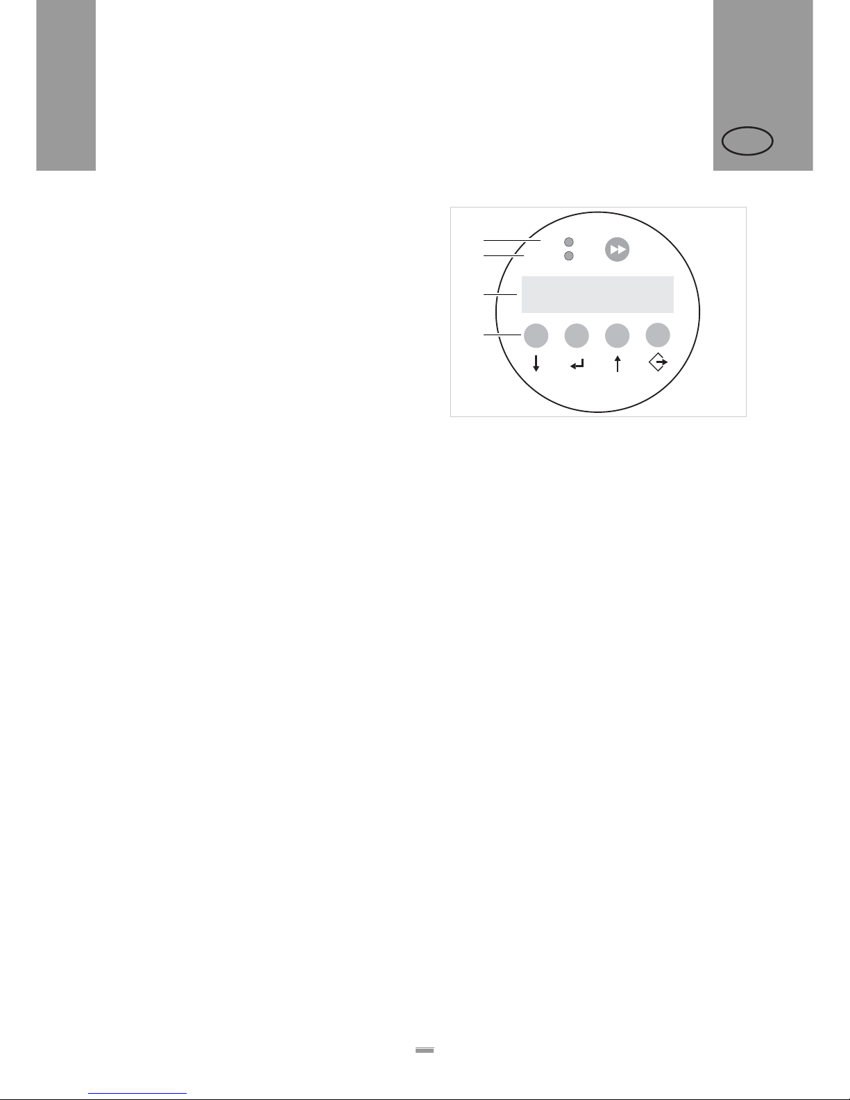
Operating LED
Lights up green when the device is switched on.
Error LED
Lights up red when an error occurs.
LCD display
– Displays functions, configured values, operating
states and error messages.
– What is displayed at any one time depends on the
operating status of the device; these screens are
explained in the section “Operating modes” on
page 26.
Buttons
The functions of the buttons depend on the operating
status of the device; these functions are exp la i ne d in
the section “Operating modes” on page 26.
Language
– The display language can be selected from a choice
of seven languages.
– Default setting is English
– For selecting another language see chapter
“Functions” on page 29
[4] The ALS20x control panel (in dispensing mode)
A Operating LED
B Error LED
C LCD display
D Buttons
+
+
–
–
ON
STATUS
Online
292
Labels
A
B
C
D
Page 15

15
2PRODUCT DESCRIPTION
2.1 OVERVIEW
ALS
20x
256
GB
2.1.3 Connection arrangement
Connections on the back of the device
[5] Connections on the back of the device (ALS20x):
A Power supply connection
B Network connection (Ethernet 10/100)
C Serial interface (RS232)
D Connection for external control panel (RS485)
E Plug-in card slot (CompactFlash cards)
F USB device interface
G PLC signal interface
H Optional: Applicator interface
For information on connecting the unit, see section “Power supply connection” on page 34.
B
C
D
E
F
G
H
A
Page 16

16
2PRODUCT DESCRIPTION
2.1 OVERVIEW
ALS
20x
256
GB
Sensor connections
[7] Arrangement of the sensor connections (schematic) on the LH
(left figure) and RH (right figure) devices:
A Product sensor
B Signal outputs (optional)
C Signal inputs (optional)
D Rotary encoder (for automatic speed adaption)
E Roll diameter sensor
F Label sensor
G (ALS20x) Alternative label sensor
H (ALS 256) Alternative label sensor
For information on connecting the sensors, see
section “Connecting sensors” on page 36.
[6] Sensor connections on the ALS20x (RH)
START
PLC-OUT
PLC-IN
LABEL
ROTARY
ENCODER
OD
CAP
CAP for 256
START
PLC-OUT
PLC-IN
LABEL
ROTARY
ENCODER
OD
CAP
CAP for 256
RHLH
A
B C
F
D E
G
A
C B
E D
F
G
H H
Page 17

17
2PRODUCT DESCRIPTION
2.1 OVERVIEW
ALS
20x
256
GB
2.1.4 Mode of operation
In labelling mode, the strip is first pulled from the label
roll around the dancer arm [8A], which consistently
maintains even tension in the label strip. The feed roller
[8D] behind the dispensing edge [8C] draws the strip
across the dispensing plate. The label is unfixed from
the backing paper on the dispensing plate and is
pressed onto the product by the pressure roller [8B].
The feed roller drives the label strip forwards the length
of one label and stops until the next product arrives at
the dispensing plate. The strip feed is started by the
product sensor mounted on the conveyor belt. The stop
control provided by the label sensor on the dispensing
edge ensures the feed is halted as soon as a gap is detected between two labels.
The spent backing paper runs from the dispensing
edge around the drive roller [8D] to the rewinder [8E].
The dancer arm regulates the rewinding speed.
The entire operation of the label dispenser is controlled
and monitored electronically. If errors occur, the device
controls output an appropriate notification for the operator. If necessary, the labelling operating mode is halted automatically. An electronic signal is output at the
same time. The signal can be fed to an external controller and evaluated.
[8] The ALS20x Label Dispenser is ready for operation in its
idle mode.
A Dancer arm
B Pressure roller
C Dispensing edge
D Drive roller
E Rewinder
D
A
E
B
C
Page 18

18
2PRODUCT DESCRIPTION
2.1 OVERVIEW
ALS
20x
256
GB
2.1.5 Technical specifications
Characteristics
1) The maximum usable dispensing speed depends on the label geometry.
For details see separate performance matrix in the service manual.
2) At a dispensing speed range of 5m/min to the max. speed
Labels
3) Depending on the dispensing edge width.
Label sensor
Power supply
4) For more information on fuses, see section “Replacing fuses” on page52.
5) Not accessible for user or service technician.
Dispensing speed 1):
ALS204
ALS206
ALS256
max. 40m/min
max. 30m/min
max. 50m/min
Labelling halt precision
2)
at the peeling edge:
±1 mm
Speed control: Fixed setting or automatic
speed adaption via the
rotary encoder
Label material: Converted self-adhesive
label material with liner
Internal rewinding yes
Material width (including
backing paper)
3)
:
ALS204
ALS206
ALS256
up to 110mm
up to 160mm
up to 160mm
Label length: 5 to 600mm
Label roll:
Winding direction
Unwinder (outer) Ø:
Rewinder (outer) Ø:
Core (inner) Ø:
inner or outer
up to 300mm
up to 200mm
38.1/76.2 /101.6mm
(1.5/3 /4")
Distance to peel edge
L-shape dispensing
edge:
V-shape dispensing
edge:
19mm
77mm
Transmission sensor: Wenglor OPT242-P800
optical, NPN
System voltage:
ALS20X
ALS256
110V (AC) at 60Hz power frequency (permissible
tolerance ±10%)
230V (AC) at 50Hz power frequency (permissible
tolerance ±10%)
100-240V (AC) at
60/50Hz power frequency (permissible tolerance
±10%)
Current consumption:
ALS20X
ALS256
max. 4A at 110V
max. 2A at 230V
max. 4A at 100V
max. 2A at 240V
Power consumption:
ALS20X
ALS256
max. 460VA
max. 460VA
Fuses:
ALS20X
ALS256
F1, F2: T5AH 250V
4)
Fuses integrated in the
power supply
5)
Page 19

19
2PRODUCT DESCRIPTION
2.1 OVERVIEW
ALS
20x
256
GB
Electronics
Interfaces
Internal Interfaces
6) Not yet available
Status messages, test functions,
product profiles
Processor: 32Bit CPU MIPS Core
RAM: 16MB
ROM: 4MB
Control panel: graphical display with
128x32 pixels, 2/4 lines,
5 buttons
Sensor interfaces for
external sensors
Label sensor:
Alternative label
sensor:
Product sensor:
APSF-sensor (Rotary
encoder):
Stock sensor:
(plug in each case 4-
pin M12)
Wenglor OPT242-P800
optical, NPN, 24V, con-
trollable sensitivity
PNP/NPN, 24V
PNP/NPN, 24V
single-phase/two-phase,
PNP/P-P, 24V, max.
20kHz
PNP, 24V
Internal sensor interfac-
es:
Material unwinder
Pressure roller
Dancer arm
Light barrier
not used
bi-phase light barrier en-
coder
PLC interface
Outputs:
Inputs:
Sub D15, optically insu-
lated, optionally via two
8-pin M12 (separate in-
puts/outputs in each
case)
4x PNP, 24V, a maxi-
mum of 500mA/channel,
total permissible output
current: 1500mA
3x PNP/NPN, 24V
Data interfaces:
Serial:
Ethernet:
USB:
CF card:
Control panel
interface:
RS232C (Sub-D9),
max. 115200 Baud
10/100 BaseT (RJ45)
Device V1.1 (USB B),
‘Full speed’ operating
mode, 12MBit/s
Slot for 1 CompactFlash
card
RS485 (Mini DIN 6 connection) for remote control
RFID Connection for RFID
read/write unit (special
equipement)
6)
Applicator Interface Connection for Applicator
Interface (AI) board (special equipement)
Connector for additional
motor driver
not used
Automatic halt, if ... the label roll is spent or
no gap was found.
...the max. admissible
number of missing labels
is reached.
Test functions: Automatic diagnostics
check when switched on
Output of system data via
data interface
Status indicators: Label counter
Operating hours counter
Storage locations for
product profiles:
up to 16
Page 20

20
2PRODUCT DESCRIPTION
2.1 OVERVIEW
ALS
20x
256
GB
Dimensions
6) Measurements without the dispensing edge br acket and dispensing edge
Environmental conditions
Integration
Certificates
– CE, TÜV/GS, FCC, CCC, GOST, NRTL, US/CA
– The regulation DIN EN 55022 demands for class A
devices the following text to be printed in the
manual:
„WARNING: This is a class A product. In a domestic
environment this product may cause radio
interference in which case the user may be required
to take adequate measures.“
– The FCC regulation demands the following
information text for class A devices:
„NOTE: This equipment has been tested and found
to comply with the limits for a Class A digital device,
pursuant to Part 15 of the FCC Rules. These limits
are designed to provide reasonable protection
against harmful interference when the equipment is
operated in a commercial environment. This
equipment generates, uses and can radiate radio
frequency energy and, if not installed and used in
accordance with the instruction manual, may cause
harmful interference to radio communications.
Operation of this equipment in a residential area is
likely to cause harmful interference in which case
the user will be required to correct the interference
at his own expense“
Width x height x depth:
6)
ALS204
ALS206
ALS256
492 x 488 x 353mm
492 x 488 x 403mm
492 x 488 x 403mm
Weight:
ALS204
ALS206
ALS256
36kg
38kg
40kg
Operating temperature: 5 to 40°C
Humidity: 30 to 85%, (non-con-
densing)
Noise
(at a distance of 1m):
72dB(A)
Protection class: IP 21
IP 65 special equipment
for ALS20X
Mounting positions: side / bottom / rear
Labelling positions: top / side / bottom
Dispensing edges: V-shape
L-shape
fixture 90° pivoting
Page 21
21
2PRODUCT DESCRIPTION
2.1 OVERVIEW
ALS
20x
256
GB
2.1.6 Design models
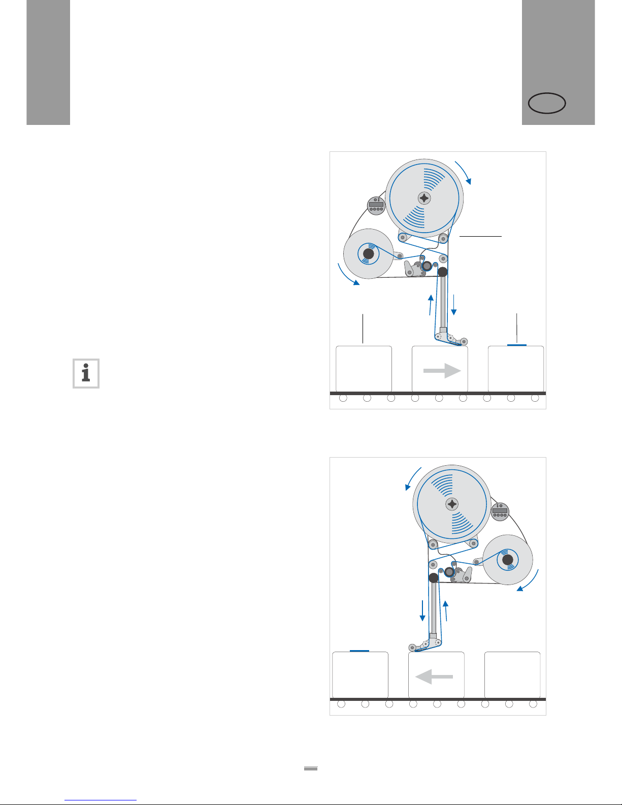
The ALS20X and ALS256 label dispensers are available in two designs for differing conveyor belt d irections.
Right-handed version
– The products are transported from left to right [9].
– The dispensing edge is located on the right side.
– Abbreviation: RH
Left-handed version
– The products are transported from right to left [10].
– The dispensing edge is located on the left side.
– Abbreviation: LH
The label dispenser operation described in this
manual is based on the right-handed version.
The left-handed version is only taken into account if the explanations or figures of the designs differ significantly.
[9] Right-handed version
A ALS20X
B Product on the conveyor belt
C Labelled product
[10] Left-handed version
A
B
C
Page 22
22
2PRODUCT DESCRIPTION
2.2 OPTIONS
ALS
20x
256
GB
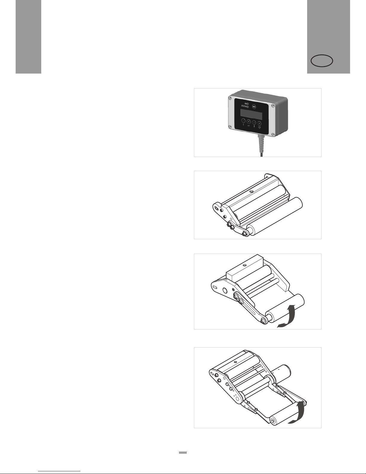
External control panel
– An external control panel can be connected in
addition to the integrated control panel.
– An external control panel is useful if the standard
control panel is difficult to access due to the position
in which the unit is installed.
Fixed dispensing edge
– The dispensing edge has a fixed connection to the
brackets.
– To adjust the vertical position, lift/lower the entire
device.
– The slope angle can be adjusted by rotating the
brackets (see the service manual for further details).
Swivelling dispensing edge
– The position of the dispensing edge can be adjusted
vertically.
– The device need not be moved to adjust the position
of the dispensing edge; the device’s mounting need
not be dismantled.
Spring-loaded dispensing edge
– The dispensing edge is pivoted. A torsion spring in
the dispensing head presses the dispensing edge
downwards and onto the surface of the product.
– Allows compensation for height differences
between the products or on the product surface.
[11] External control panel
[12] Standard dispensing edge
[13] Swivelling dispensing edge
[14] Spring-loaded dispensing edge
2.2 OPTIONS
Page 23
23
2PRODUCT DESCRIPTION
2.2 OPTIONS
ALS
20x
256
GB
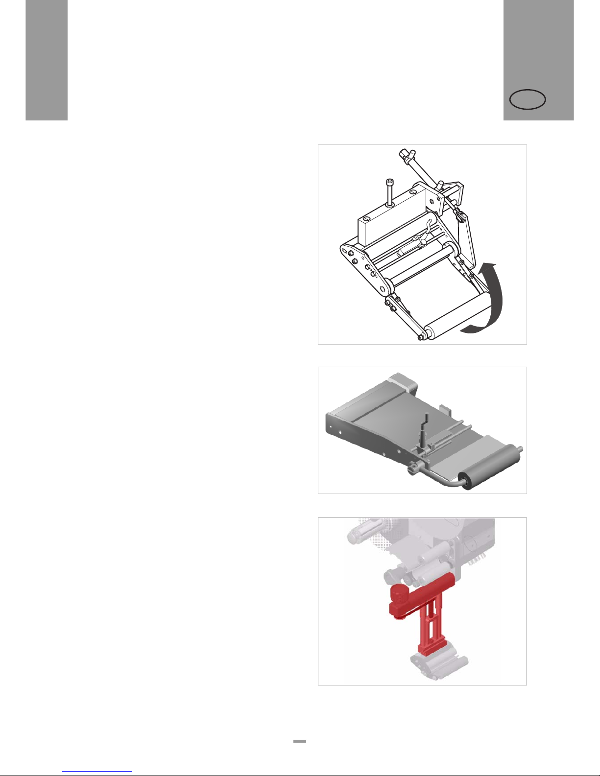
Pneumatic dispensing edge
– The dispensing edge is pivoted in the dispensing
head. Compressed air presses the dispensing edge
onto the surface of the product.
– Allows compensation for height differences
between the products or on the product surface.
V-shape dispensing edge
Not for ALS256!
– An alternative for applications which do not leave
enough space for the standard dispensing edge holder, which juts out to the bottom side.
– Is attached directly to the machine
Adjustable dispensing edge holder
Enables a vertical fine adjustment of the dispensing
edge towards the product without moving the machine.
[15] Pneumatic dispensing edge
[16] V-shape dispensing edge
[17] Adjustable dispensing edge holder (pictured red resp. dark
gray)
Page 24
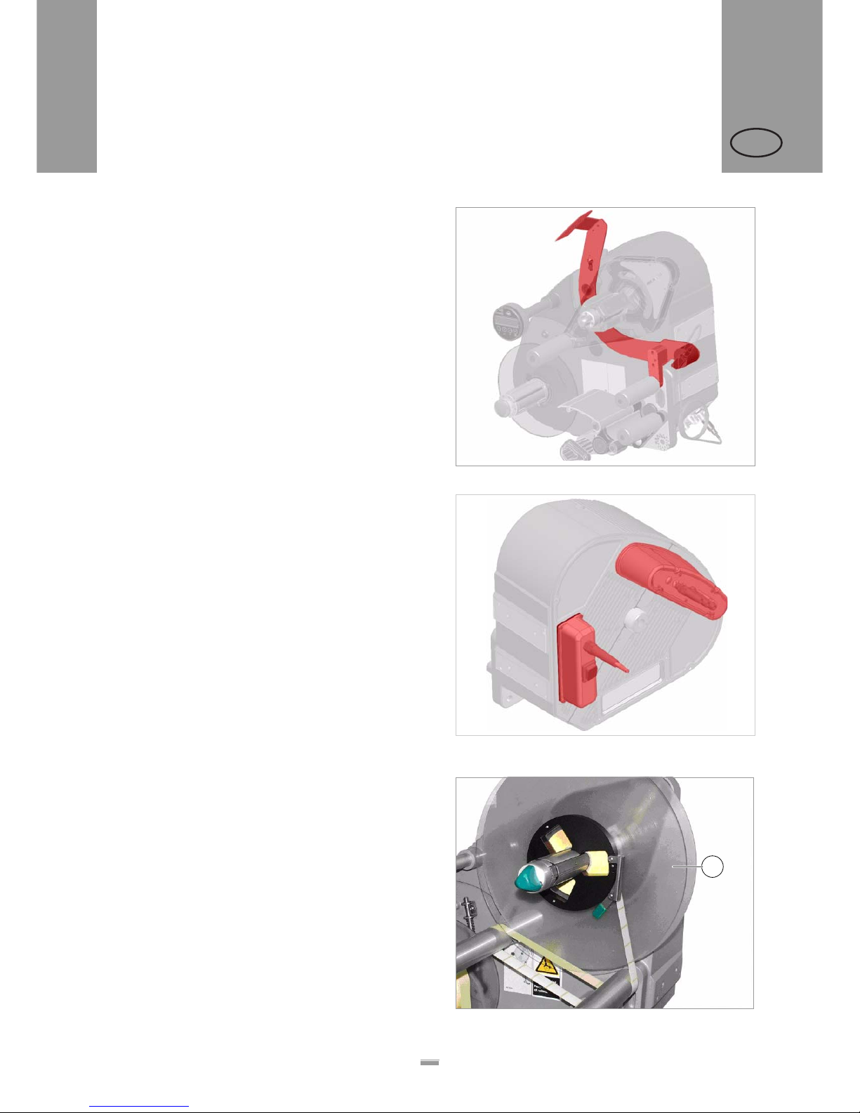
24
2PRODUCT DESCRIPTION
2.2 OPTIONS
ALS
20x
256
GB
Outer Diameter control sensor
The outer diameter control sensor (OD sensor) triggers
a warning, if the label roll outer diameter falls below a
certain, adjustable value.
Dust/Splash guard
Available only for ALS20X.
Additional sealing of the electrical connections an d of
the housing fulfils the requirements of the IP65 protection class [19].
Additional material guide disk
The additional material guide disk [20A] improves the
lateral guiding of the material roll. This option is especially recommended, if very narrow material (< 30mm
width) is processed.
[18] OD sensor (pictured red resp. dark gray)
[19] Dust/splash guard of the electrical connections (pictured red
resp. dark gray)
[20] Additional material guide disk (A)
A
Page 25
25
2PRODUCT DESCRIPTION
2.2 OPTIONS
ALS
20x
256
GB
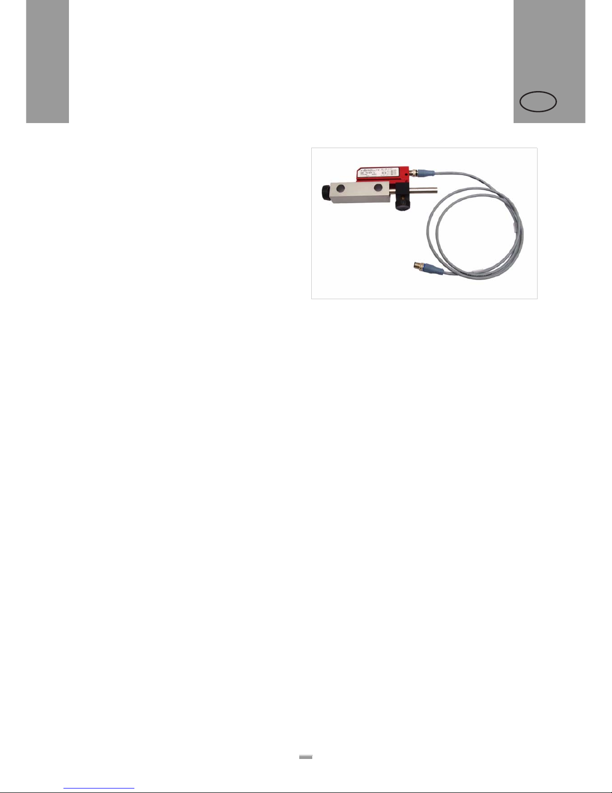
Capacitive label sensor
Optional sensor, required for processing transparent
labels [21]. The sensor is mounted to the rods of the
dispensing edge holder.
Printer
– If necessary, you can mount a hot stamp printer (not
available from Avery Dennison) onto the holder
brackets of the dispensing edge.
– Example of use: Printing consecutive numbers onto
labels.
Applicator
If it is not possible to label directly from the dispensing
edge, you can fit an applicator to the label dispenser.
Various types of applicators are available that depend
on the given requirements.
Simple applicators can be controlled directly via the
PLC signal interface [5G] that is available as standard.
Applicator interface
Additional board [5H]; allows almost all types of applicators to be controlled.
Narrow label spring kit
Narrow label material may under certain circumstances
tear off or expand in a way which results in poor labelling precision. In those cases, it is adviseable to install
weaker dancer arm springs.
[21] Capacitive label sensor with bracket and cable.
Page 26
26
2PRODUCT DESCRIPTION
2.3 OPERATING MODES
ALS
20x
256
GB
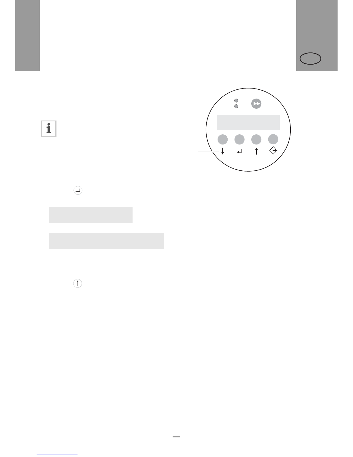
2.3.1 Dispensing mode
This is the operating mode of the unit when switched
on. You can carry out the functions listed in the sections
below.
If text such as ‘Prof 5 xxxxxxxx’ is displayed
instead of ‘ONLINE’:
– The ‘xxxxxxxx’ product profile (mem o ry
location 5) is activated.
– For more information, see the ‘Using product
profiles’ section.
Stopping/Continuing the dispensing
Stopping the dispensing:
£ Press the button.
– The dispenser stops.
– One of the two texts appears:
or
1) Second line = scroll text.
Continuing the dispensing:
£ If the lower text is displayed: Remove the label from
the applicator.
£ Press the button.
Changing the counter reading
£ Set the counter reading using the MACHINE SETUP >
Dispense counter function.
Starting the unit in configuration mode
To start the unit in configuration mode:
£ Set MACHINE SETUP > Turn-on mode to ‘Offline’.
Counting labels backwards
To count dispensed labels backwards from a starting
value to zero:
£ Set LABEL SETUP > Stop count. mode to ‘Enabled’.
£ Use the LABEL SETUP > Label stop quan. function to
define the starting value.
ONLINE
Stopped. press
Ç key to start.
1
ONLINE
Stopped. remove label. press
Ç key to start.
1
[22] Control panel in dispensing mode (292 labels dispensed)
A Explanation of buttons in dispensing mode
+
+
–
–
ON
STATUS
Online
292
Labels
A
2.3 OPERATING MODES
Page 27
27
2PRODUCT DESCRIPTION
2.3 OPERATING MODES
ALS
20x
256
GB
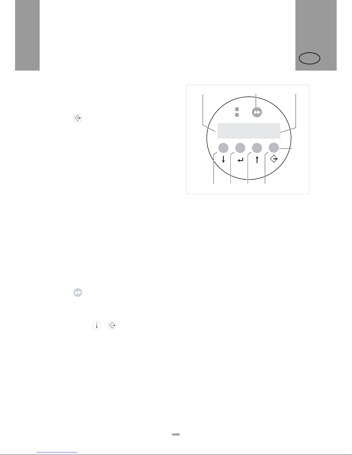
Online settings
The machine is in dispensing mode.
To switch to the online settings mode:
£ Press the button.
– The display shows the dispensing speed [23A] and
the start offset [23C].
– The button assignments are as shown on the
buttons.
– You can increase (‘+’ button) or lower (‘–’ button)
both settings in the dispensing mode [23D].
Dispensing speed:
– Setting range:
ALS204: [5.0…40.0] m/min
ALS206: [5.0…30.0] m/min
ALS256: [5.0…50.0] m/min
– Display fix: The dispensing speed is constant.
– Display var: The dispensing speed automatically
adjusts to the speed of the conveyor belt (‘speed
adaption’).
Start offset:
– Setting range: [0.0…999.9] mm
– The start offset indicates the distance between the
product sensor and the dispensing edge.
Dispensing manually
– To manually trigger the dispensing of individual
labels:
£ Press the button.
– Dispensing speed: As specified in the setting (see
above).
To switch back to dispensing mode:
£ Press the buttons + .
[23] Control panel in the online settings mode
A Dispensing speed display (here: 12.2 m/min constant)
B Dispense label button
C Start offset display (here: 0 mm)
D Explanation of buttons in online settings mode
E Button to lower dispensing speed
F Button to increase dispensing speed
G Button to lower start offset
H Button to increase start offset
+
+
–
–
ON
STATUS
Speed
12.2 fix
Offset
0.0
ABC
D
EFGH
Page 28
28
2PRODUCT DESCRIPTION
2.3 OPERATING MODES
ALS
20x
256
GB
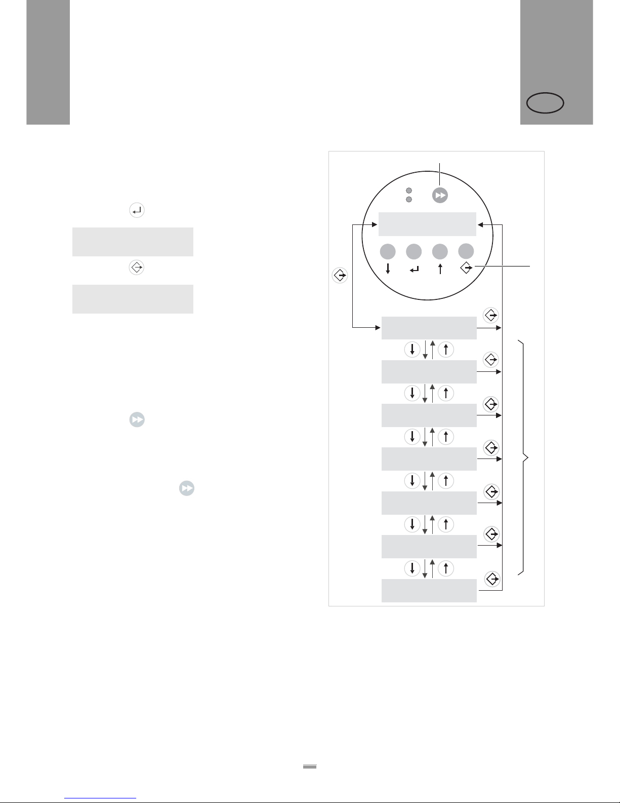
2.3.2 Configuration mode
The machine is in dispensing mode.
Switching to configuration mode:
£ Press the button twice.
– Display:
£ Press the button.
– Display:
– LABEL SETUP is the name of the first menu that is
currently active.
– In configuration mode, the button assignments are
as shown below the buttons.
Function of the double-arrow button
To dispense individual labels:
£ Press the button briefly (less than two
seconds).
– Dispensing speed: As specified in the configuration;
‘Speed Adaption’ is not active.
To automatically calibrate the label length:
£ Hold down the button for a while (longer than
two seconds).
Menus
In configuration mode, you have access to several
menus providing a fixed sequence of functions that can
be carried out.
You can set the unit so that some of the menus a re not
shown.
Figure [24] shows the button functions for switching
between the individual menus and for leaving them.
OFFLINE
LABEL SETUP
[24] Menu selection and button functions in configuration mode.
A Button for triggering a dispensing procedure and for
starting the measurement of lengths.
B Explanation of buttons in configuration mode
C Menus
ON
STATUS
+
+
–
–
LABEL SETUP
MACHINE SETUP
INTERFACE. PARA
OFFLINE
I/O BOARD
APPLICATOR PARA
SERVICE/DIAGNOS.
SERVICE DATA
A
B
C
Page 29
29
2PRODUCT DESCRIPTION
2.3 OPERATING MODES
ALS
20x
256
GB
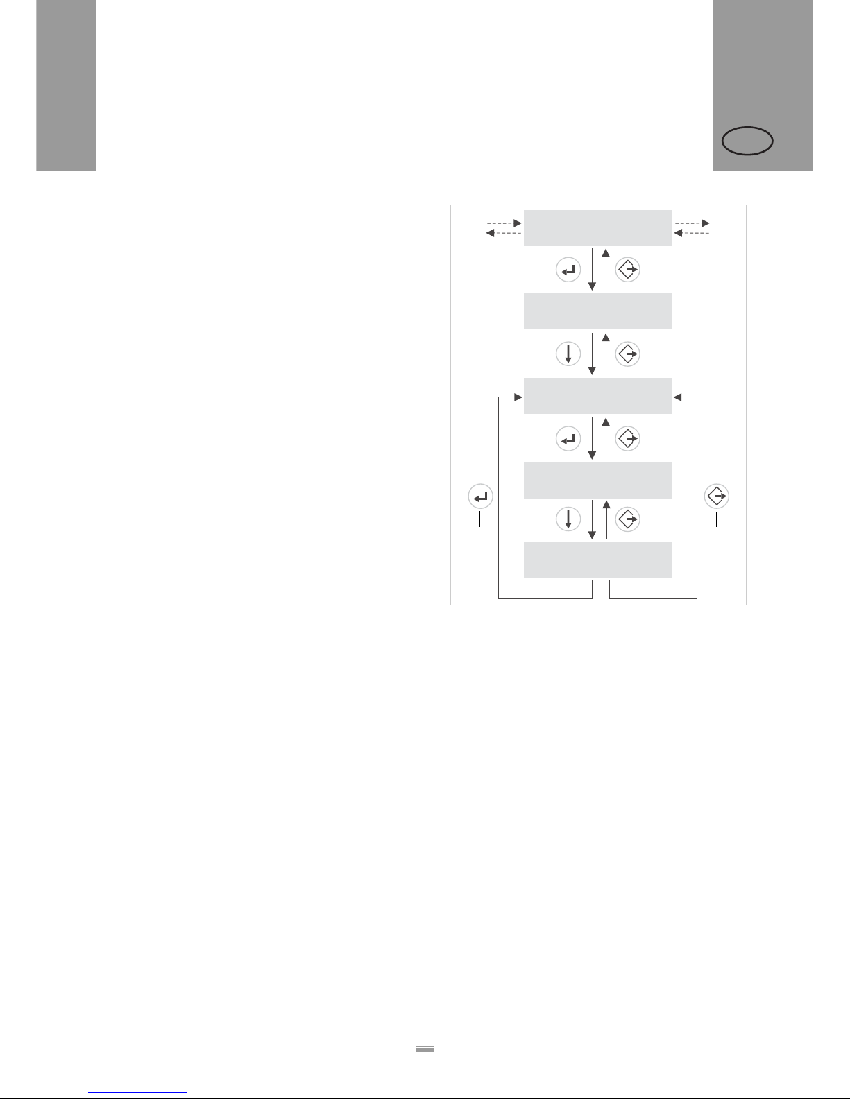
Functions
Every submenu contains functions for setting the unit
controls.
Figure [25] shows the button functions for changing
settings using the MACHINE SETUP > Language function as
an example.
[25] Button functions for setting the MACHINE SETUP >
Language function.
A Button to ‘Accept changes’
B Button to ‘Cancel changes’
4x
MACHINE SETUP
Language
English
Language
German
MACHINE SETUP
Store Prod.Prof.
MACHINE SETUP
Language
AB
Page 30
30
2PRODUCT DESCRIPTION
2.4 FUNCTION DESCRIPTIONS
ALS
20x
256
GB
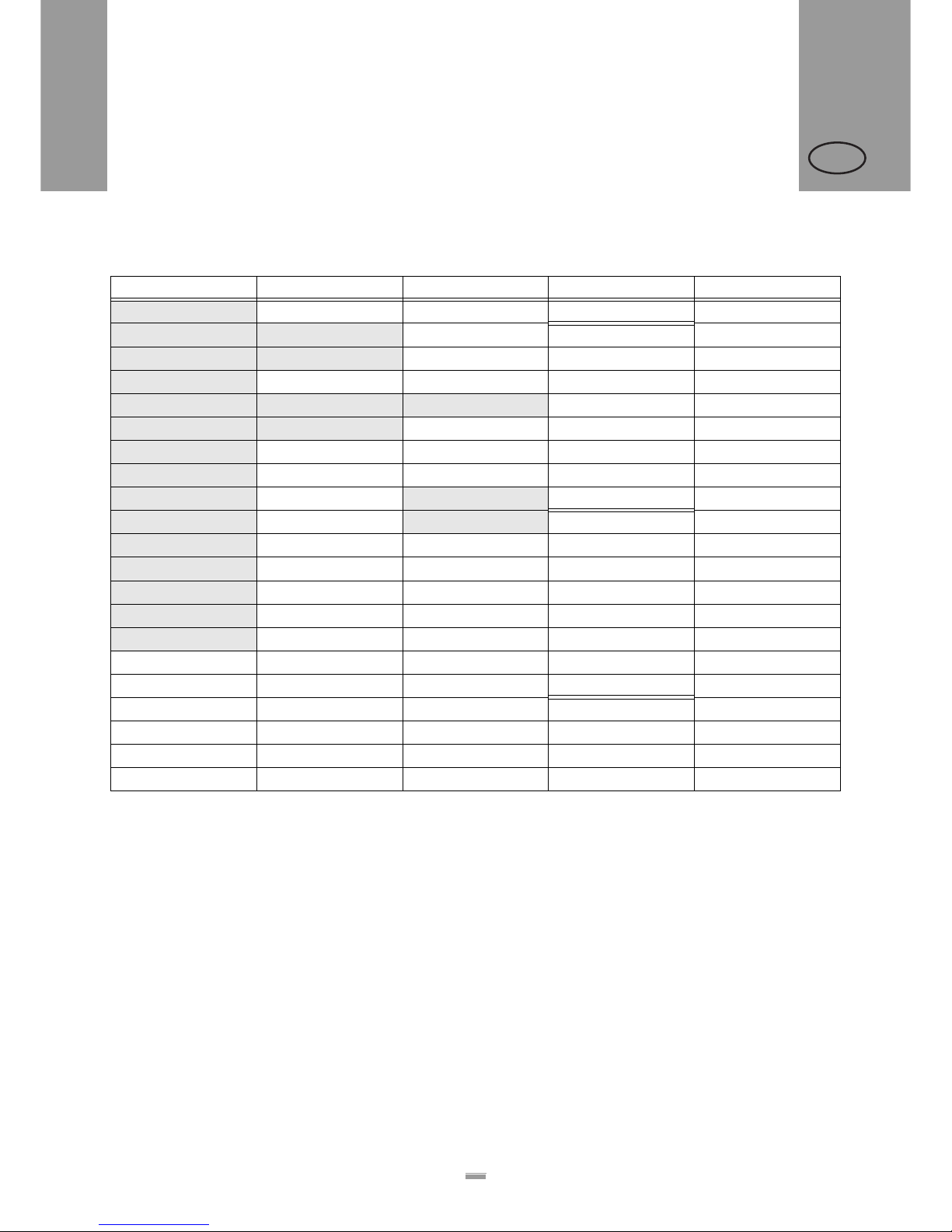
2.4.1 Overview of functions
[26] Functions menu – part 1 (grey shading = function is described in
the following).
1) Only appears if LABEL SETUP > Multi label mode = „2labels/start“ oder
„3 labels/start“
2) Only appears if LABEL SETUP > Stop count. mode = Enabled
3) Only appears if MACHINE SETUP > Light sens. type = Wenglor
4) Only appears if MACHINE SETUP > Speed Adaptio n = On
5) Only appears if MACHINE SETUP > Tandem Operation = „Master“,
„Flipflop master“ or „Slave“
6) Only appears if „Tandem Operation“ = „Master“ or „Master flipflop“ and if
„Tandem Synch.“ = „UDP Tandem Port“
7) Only appears if MACHINE SETUP > OD Sensor mode = „Error“ or
„Warning“
8) Only appears if INTERFACE PARA > NETWORK PARAM.> Time client =
Enabled
LABEL SETUP MACHINE SETUP
(continued)
INTERFACE PARA
(continued)
Load prod.profil Dispenser type Light sens. type > EASYPLUGINTERPR Port address
Gap detect mode Store prod.prof. Labelsen. InType Interface Ethernet speed
Dispense speed Del. prod.profil Startsen. In.Typ Spooler mode MAC Address
Slew speed Dispense counter Start disp. mode Dispenser ID no. SNMP Agent
Label pitch Turn-on mode Start error stop Spooler size SNMP Password
Lab. stop offset Language On inhibit enter Offline mode FTP server
Start offset Access authoriz. On inhibit leave Interface delay FTP Password
Product length Default values Apply key WEB server
Multi label mode Factory settings Material end err > COM1 PORT WEB display refr.
Label 2 offset
1
Store parameters Material end war n Baud rate WEB admin passw.
Label 3 offset
1
Auto Sensor Adj.
3
OD Sensor mode No. of data bits WEB supervisor p.
Miss. label tol. Sensor Adjust
3
OD Sens. polarity 7Parity Time client
Miss. label mode Speed Adaption Stop bits Time server IP
8
Stop count. mode Encoder Type
4
Data synch. Sync interval
8
Label stop quan.
2
Encoder Resol.
4
Frame error DHCP host name
Encoder Diameter
4
Rew. operation > NETWORK PARAM.
Tandem Operation IP Addressassign
Tandem Synch.
5
IP address
Slave IP address
6
Net mask
Tandem Distance
5
Gateway address
2.4 FUNCTION DESCRIPTIONS
Page 31
31
2PRODUCT DESCRIPTION
2.4 FUNCTION DESCRIPTIONS
ALS
20x
256
GB
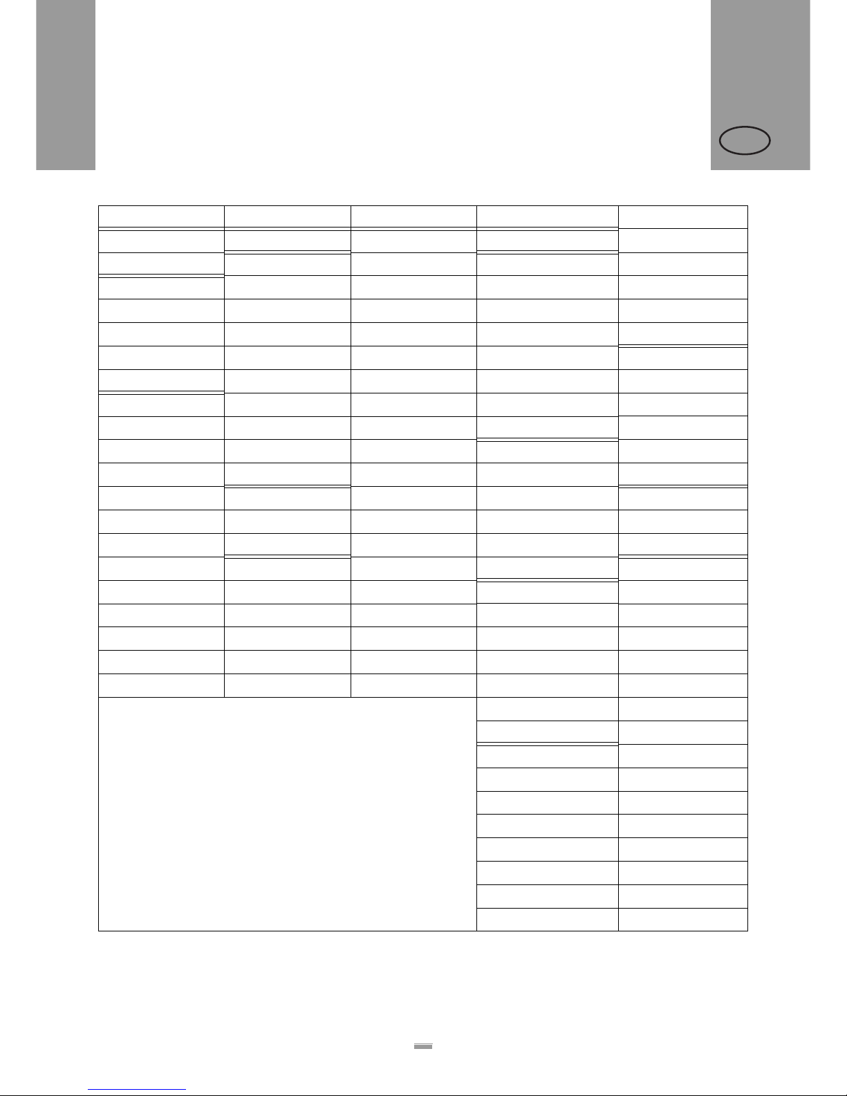
[27] Functions menu – part 2.
SIGNAL INTERFACE
(continued)
SERVICE/DIAGNOS. SERVICE DATA
(continued)
Interface mode > AI BOARD SIGNAL
14
Service > MODULE FW VERS. Manufacturer
> PLC SIGNALS
9
Applicator type Serv. data reset System version Work place
End dispense mod Apply mode Sensor Test System revision Company name
Disp. end delay Start mode Memory card test System date
End pulse width Dwell time
11
Test functions Bootloader > DISPLAY DATA
Blow on time
12
Store diagnosis uMon Display version
> APPLIC. SIGNALS
10
Restart delay Data blocks del. Applicator int.
16
Display serial nr.
Applicator type Position timeout
13
Remote disp. vers.
17
Status outputs Apply comp. time > OPERATION DATA Remote disip. #
17
Apply mode Serv. operations
Dwell time
11
> AI BOARD SIGNAL
15
Tot. mat. length > CF CARD SLOT
Blow on time
12
Status signals Dispensing cycl. Card in slot
Restart delay Operation time
Position timeout
13
> ACTIVE INPUTS > MEMORY DATA
Apply comp. time Start signal > POWERSUPPLYDATA Ram memory size
Inhibit signal Type Flash mem size
OD sensor signal Version CompactFlash
18
Serial number Default values
PS Temperature
Standby+On time
9) Only appears, if Interface mode = „PLC signals“
10)Only appears, if Interface mode = -“Applic. signals“
11)Only appears if applicator type = PEP, „PEP Blow on“, „Reverse PEP“, BTS or
„LA-TO timed“
12)Does not appear if applicator type = „LTP-LTPV“, PEP, „Direct dispense“ or LA-TO
13)Does not appear if applicator type = ASA, „Direct dispense“ or LA-BO
14)Only appears with AI board installed and if Interface mode = „Applic. signals“
15)Only appears with AI board installed and if Interface mode = „PLC signals“
16)Only appears with AI board installed
17)Only appears if remote display is connected
18)Only with plugged-in CF-card
> CPU BOARD DATA
CPU identifier
PCB Revision
FPGA version
MAC Address
Serial number
Production date
PCB part number
Board part numb.
Page 32

32
2PRODUCT DESCRIPTION
2.4 FUNCTION DESCRIPTIONS
ALS
20x
256
GB
2.4.2 Notes
Function descriptions
The following chapters only describe those functions
that are necessary for operating an ALS20x/256 that
has been configured and set up. These functions are
highlighted in grey in the overview.
Settings of functions that are not described in
the following may only be changed by qualified
service technicians. These functions are
described in the service manual.
The settings range or the individual settings for
a function are shown in square brackets.
– The default value is italicised for functions
that have individual settings.
– Settings that consist of several words are
shown in quotation marks.
Quick setting
[28] Button combinations for quick setting of functions with a huge
value range.
2.4.3 LABEL SETUP menu
Load prod. profil function:
– Loads product profiles from the internal database.
– Produ ct pr of ile s co ntain product-specific settings.
– You can select a maximum of 16 product profiles.
– You can only select product profile numbers that
have profiles already stored for them.
– See chap. “Loading a product profile” on page 50.
Gap detect mode function:
– After one of the following events, the printer must
always search for the punch, that is initialize the
label material: a
fter switching the device on; after
changing the label material.
– Settings: [Manual, „Autom. Forward“]
Manual: The operator has to initialize the material
always manually by pressing the feed key several
times.
Autom. Forward: The material initialization is always
done automatically, if necessary.
Dispense speed function:
– The speed at which the label is dispensed
– Setting range:
ALS204: [5.0…40.0] m/min; default: 10.0
ALS206: [5.0…30.0] m/min; default: 10.0
ALS256: [5.0…50.0] m/min; default: 10.0
– See chap. “Dispensing speed” on page 46.
Slew speed function:
– Feed speed during initialisation
– Setting range:
ALS204: [5.0…40.0] m/min; default: 1.0
ALS206: [5.0…30.0] m/min; default: 1.0
ALS256: [5.0…50.0] m/min; default: 1.0
Label pitch function:
– Label pitch = label length+space
– Setting range: [5.0…600.0] mm
– See chap. “Label pitch” on page 45.
Lab. stop offset function:
– Stop position of the label on the dispensing plate
– Setting range: [0.0…999.9] mm; default: 20.0
– See chap. “Label stop position” on page 45.
Start offset function:
– Distance between the product sensor and the top of
the dispensing plate
– Setting range: [15.0…2999.9] mm; default: 15.0
– See chap. “Label position on the product” on
page 47.
Product length function:
– With this function activated, the machine ignores all
start signals, until the product has passed the
dispensing edge
– Setting range: [0.0…1999.9] mm; default: 0.0
– See chap. “Suppressing start signals” on page 46.
Multi label mode function:
– Settings: [Disabled, „2 labels/start“, „3 labels/start“]
Disabled: Each start signal causes printing of one
label.
„2 labels/start“: Each start signal causes printing of
2 labels.
Buttons Effect
+ Decrease value with 10fold speed.
+ Increase value with 10fold speed.
+ Reset value to lowest setting.
Page 33

33
2PRODUCT DESCRIPTION
2.4 FUNCTION DESCRIPTIONS
ALS
20x
256
GB
„3 labels/start“: Each start signal causes printing of
3 labels.
Label 2 offset function:
– Defines the distance of the 2nd label for the
LABEL SETUP > Multi label mode function (see above).
The distance is measured from the front label edge
of the preceding label.
– Setting range: [x…9999.9]mm; Default: x, with
x = LABEL SETUP > Label pitch.
Label 3 offset function:
– Defines the distance of the 3rd label for the
LABEL SETUP > Multi label mode function (see above).
The distance is measured from the front label edge
of the preceding label.
– Setting range: [x…9999.9]mm; Default: x, with
x = LABEL SETUP > Label pitch.
Miss. label tol. function:
– Missing label tolerance
– The maximum permissible number of successive
missing labels on the label strip
– Setting range: [0…10] mm; default: 1
– See chap. “Missing labels” on page 49.
Stop count. mode function:
– Settings: [enabled, disabled]
Enabled: Dispenser counter counts backwards,
starting with the value that has been set using the
LABEL SETUP > Dispense counter function. When the
counter reaches zero, no further labels are
dispensed.
Disabled: The dispenser counter counts forwards,
which means that the dispenser counter is
incremented with each label that is dispensed.
Label stop quan. function:
– After this amount of dispensed labels, the dispenser
stops
– Function only appears, if LABEL SETUP >
Stop count. mode = „Enabled“
– Setting range: [0…99999]; default: 0
2.4.4 MACHINE SETUP menu
Store prod. prof. function:
– Storing a prod uct profile, see chap. “Storing a
product profile” on page 50.
Del. prod.profile function:
– Deleting a product profile, see chap. “Deleting a
product profile” on page 51.
Start error stop function:
– Determines how the machine responds in the event
of a product start error. A product start error o ccurs
when a new start signal arrives before the current
dispensing cycle has ended.
– Settings: [On, Off]
On: Start errors are issued. If a start error occurs,
the device stops and displays a relevant error
message.
Off: Start errors are ignored.
Turn-on mode function:
– The operating mode of the unit after it is turned on.
– Settings: [Online, Offline]
Online: Dispensing mode
Offline: Configuration mode
Language function:
– Language of the displayed text
– Settings: [English, French, German, Spanish,
Italian, Dutch, Danish, Polish, Turkish]
Material end err function:
– Refers to the internal OD control.
– Settings: [On, Off]
On: Material end triggers a status message.
Off: Material end triggers no status message.
Material end warn function:
– Refers to the internal OD control.
– Defines the critical roll diameter.
– Adjustment range: [50…500]mm; Default setting:
80mm
Page 34
34
3BEFORE OPERATION
3.1 ELECTRICAL CONNECTIONS
ALS
20x
256
GB
3.1.1 Power supply connection
WARNING!
This machine operates using mains voltage!
Touching live electrical parts may exp ose
you to hazardous electrical currents and
may lead to burns.
£ Make sure that the device is switched off
before you connect the power cable.
£ Only connect the unit to a grounded
power socket fitted to authorised
standards.
£ (ALS 20X) Only operate the device with
the mains voltage set on the voltage
selector switch.
£ (ALS 20X) Ensure that the unit is set to
receive the mains voltage supplied by
your electricity provider.
£ (ALS 256) Only operate the device using
the system voltage indicated on the
nameplate.
£ The power cable should not be more than
3 m long.
The device is only completely disconnected
from the mains if the power cable is
unplugged. Therefore:
£ Make sure the power supply socket is
accessible.
£ In case of emerg en c y, switch off the
device and disconnect the power cable!
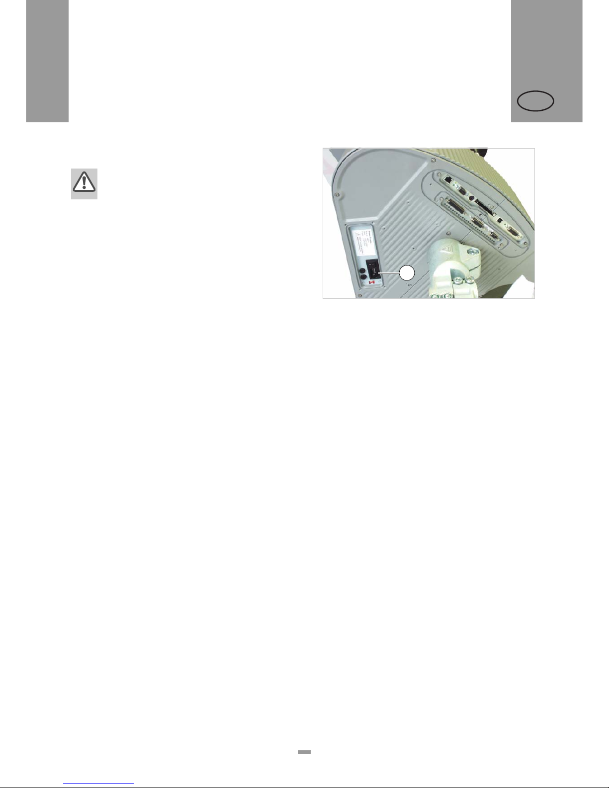
[29] Power supply (A) on the ALS 20X
A
3 BEFORE OPERATION
3.1 ELECTRICAL CONNECTIONS
Page 35
35
3BEFORE OPERATION
3.1 ELECTRICAL CONNECTIONS
ALS
20x
256
GB
Checking the power supply setting
ALS256: A power supply setting is not required.
The ALS20X Label Dispenser is suitable for
operation with a power supply of 230V (AC) or
110V (AC).
If you are unsure of what mains voltage your
local electricity supplier provides, refer to a
qualified service technician.
£ Check to see that the voltage that has been set
conforms to the local mains voltage.
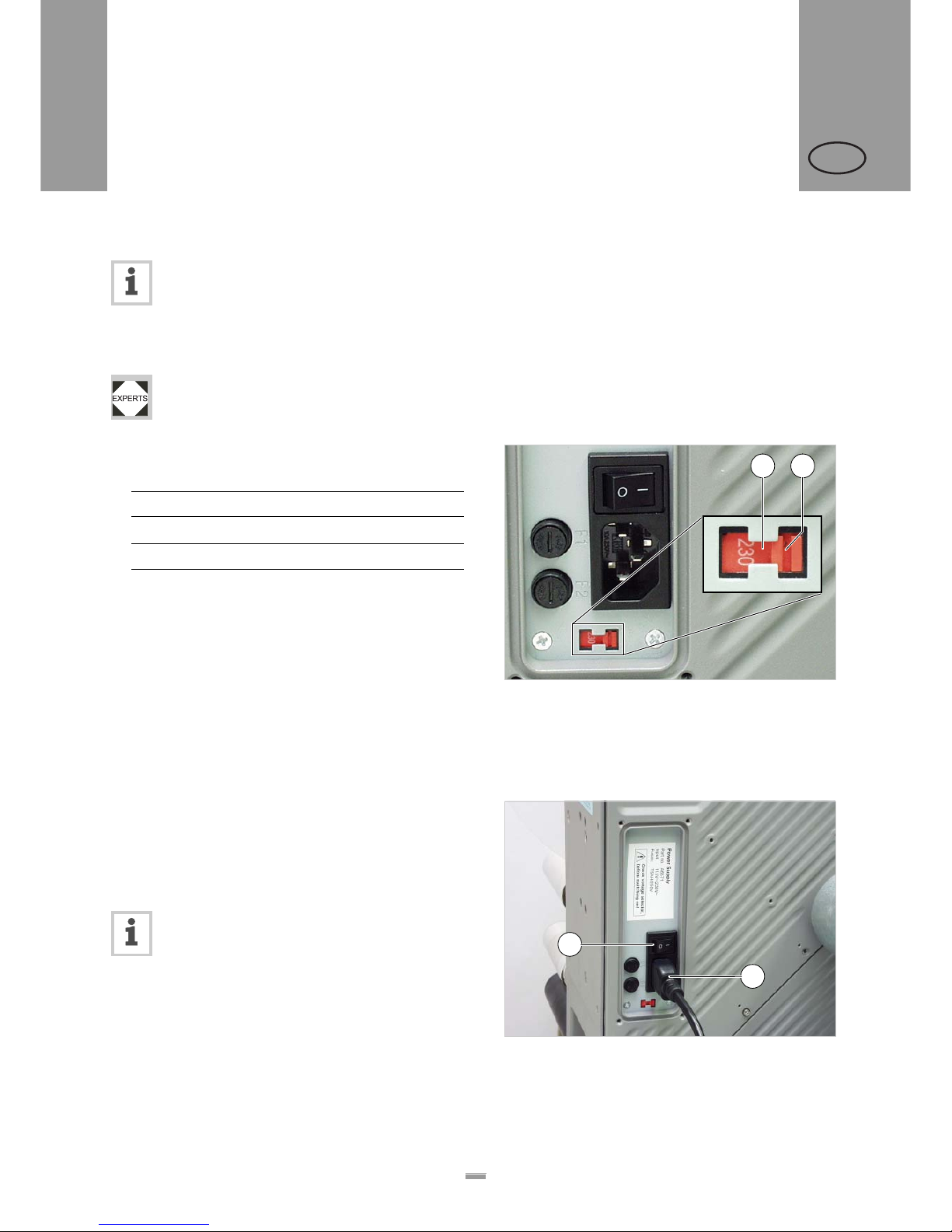
[31] Permissible mains voltages for both positions on the voltage
selector switch.
Changing the voltage setting:
£ Make sure that the power cable is
disconnected.
£ Slide the switch [30A] to the respective
opposite position.
– Insert a small screwdriver into the groove [30B] and
move the red insert horizontally to the opposite stop
position (to the left in Figure
[30]).
Connecting the power cable.
£ Make sure that the power switch [32A] is set to ‘O’
(off).
£ Using the supplied power cable, plug the unit into a
socket connected to the mains supply.
For more information on fuses, see section
“Replacing fuses” on page 52.
Switch setting Permissible mains voltage
115 100–120V (AC)
230 200–240V (AC)
[30] Voltage selector switch on the ALS 20X (set to 230 V in the
figure)
A B
[32] Power cable (B) plugged in.
B
A
Page 36
36
3BEFORE OPERATION
3.1 ELECTRICAL CONNECTIONS
ALS
20x
256
GB
3.1.2 Connecting sensors
£ Check whether the required sensors are connected
before turning on the unit [33].
The minimum required sensors:
– Label sensor (installation location: dispensing edge)
– Product sensor (installation location: conveyor belt)
Additional optional sensors:
– Rotary encoder (required for speed adaption)
– External outer diameter checking sensor (provides
advance warning of the end of a label roll)
– Alternative label sensor; for example, capacitive
sensor, used to detect transparent labels.
You can find further information regarding
suitable sensor types, pin assignments, and so
on in the service manual.
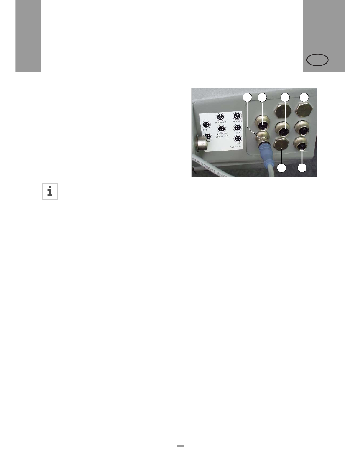
[33] Sensor connectors:
A Label sensor
B Product sensor
C Optional: Rotary encoder
D Optional: Roll diameter check
E (ALS 20x) Optional: Alternative label sensor
F (ALS256) Optional: Alternative label sensor
C D
EF
BA
Page 37
37
3BEFORE OPERATION
3.2 INSERTING LABEL MATERIAL
ALS
20x
256
GB
3.2.1 Prerequisites
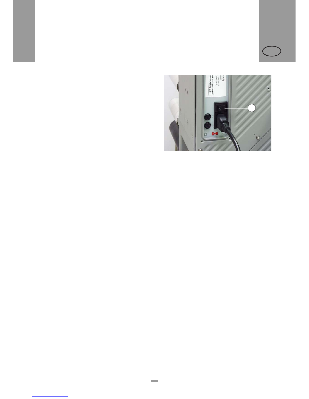
– The label dispenser is turned off at the main
switch [34A] (switch set to ‘O’).
£ Check that the safety installations are working
properly.
£ Inspect the machinery for any visible damage.
Report any defects immediately.
£ Remove any unnecessary materials and objects
from the operating area of the unit.
£ Make sure that only authorised persons are within
the operating range of the machine.
£ Use the required personal protective equipment
correctly; forexample, wear a hairnet, safety
glasses.
[34] Main switch on the housing.
A
3.2 INSERTING LABEL MATERIAL
Page 38
38
3BEFORE OPERATION
3.2 INSERTING LABEL MATERIAL
ALS
20x
256
GB
3.2.2 Inserting a label roll
WARNING!
Risk of injury due to moving and rapidly
rotating parts!
£ Before inserting the label roll, ensure that
the device is turned off at the main
switch.
£ Do not under any circumstances turn the
device on before the label strip is
threaded in completely.
Removing spent backing paper
Assuming backing paper has gathered on the rewinder
[35A] :
£ Press the release button [35B].
– The tensioning mechanism of the rewinder is
slackened.
£ Remove the rewound backing paper.
Removing glue residue
£ If necessary, clean the following components:
– Dispensing plate
– Deflection rollers
– Drive rollers
– Pressure roller
£ Follow the directions provided in section
“Maintenance and cleaning” on page 52.
Inserting a new label roll
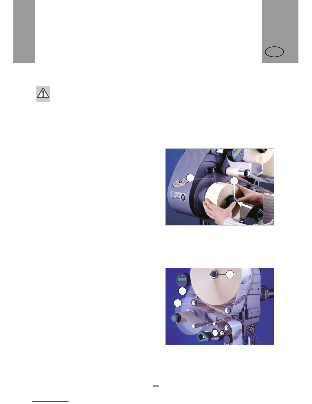
£ Push the material roll [36A] onto the unwinder as far
as it will go.
£ Rotate the rotary knob [36B] in a clockwise direction
until the label roll sits tightly.
£ Run the label strip around the dancer arm as shown
in the figure [36C].
[35] A Rewound backing paper
B Release button
C Backing paper path
B
A
[36] Inserting the material roll – Part 1.
A
C
B
Page 39
39
3BEFORE OPERATION
3.2 INSERTING LABEL MATERIAL
ALS
20x
256
GB
3.2.3 Threading the label roll
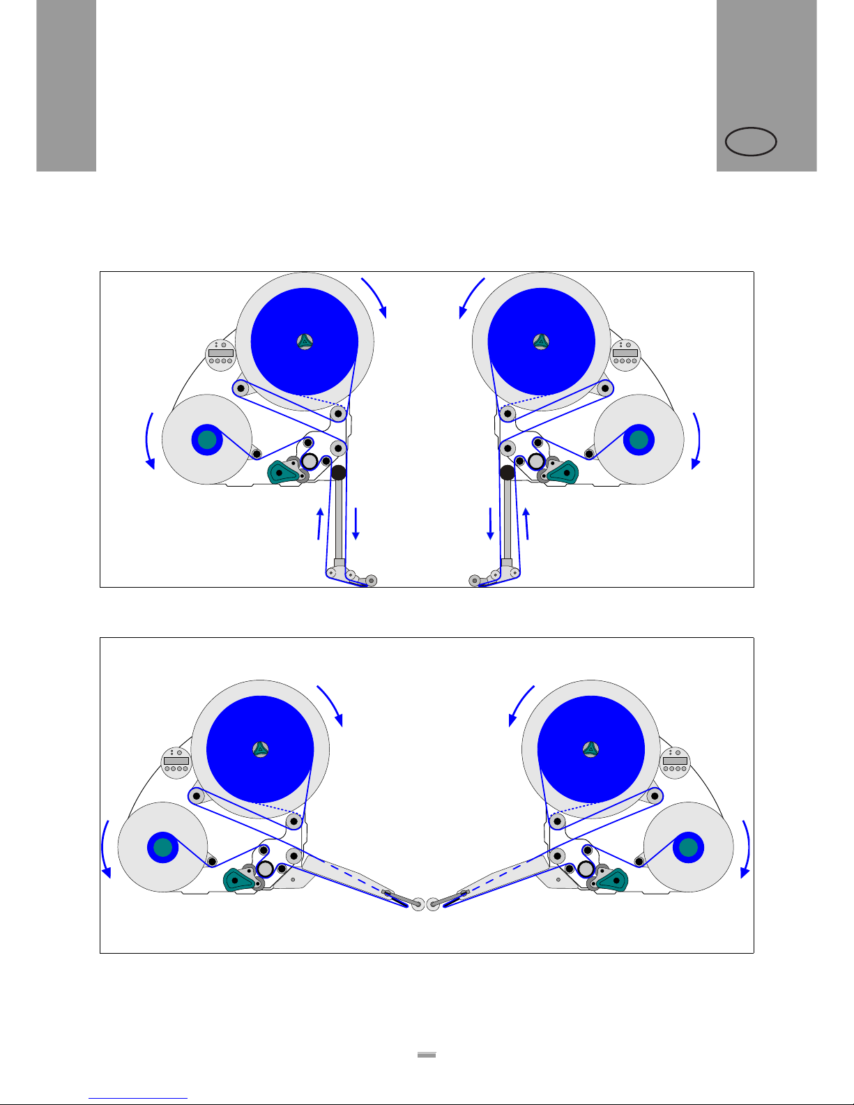
Threading guide
[37] Threading guide for ALS20x/256 with L-shape dispensing edge *.
A Right-handed version B Left-handed version
[38] Threading guide for ALS20x/256 with V-shape dispensing edge
*
.
A Right-handed version B Left-handed version
*) Solid line: Path for label rolls with labels facing outwards. Dottet line: differing path for label rolls with labels facing inwards.
BA
BA
Page 40
40
3BEFORE OPERATION
3.2 INSERTING LABEL MATERIAL
ALS
20x
256
GB
Threading the label roll at the dispensing
edge
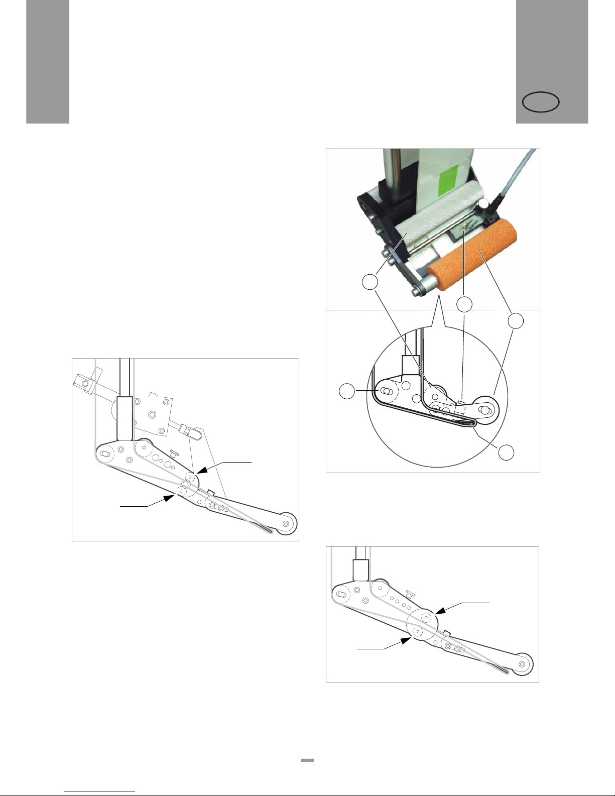
Fixed [39] (standard) and pivotable L-Shape dispensing edges:
£ Unroll around 1m of label strip and remove the
labels from it.
£ Pass the backing paper around the first deflection
roller [39A] and through the slot in the sensor [39B].
£ Feed the backing paper under the pressure roller
[39C] to the dispensing plate [39D].
£ Feed the backing paper around the dispensing plate
to the second deflection roller [39E].
Spring loaded [40] and pneumatic [41] L-Shape di spen-
sing edges:
£ Additionally pass the backing paper between the
two slim deflection rollers at the joint [40A] [41A].
[41] Path of the label strip at the pneumatic dispensing edge (option).
[39] Path of the label strip at the dispensing edge.
A 1st deflection roller
B Label sensor
C Pressure roller
D Dispensing plate
E 2nd deflection roller
[40] Path of the label strip at the spring loaded dispensing edge
(option).
C
A
B
D
E
A
A
A
A
Page 41
41
3BEFORE OPERATION
3.2 INSERTING LABEL MATERIAL
ALS
20x
256
GB
Threading the label roll onto the drive
roller
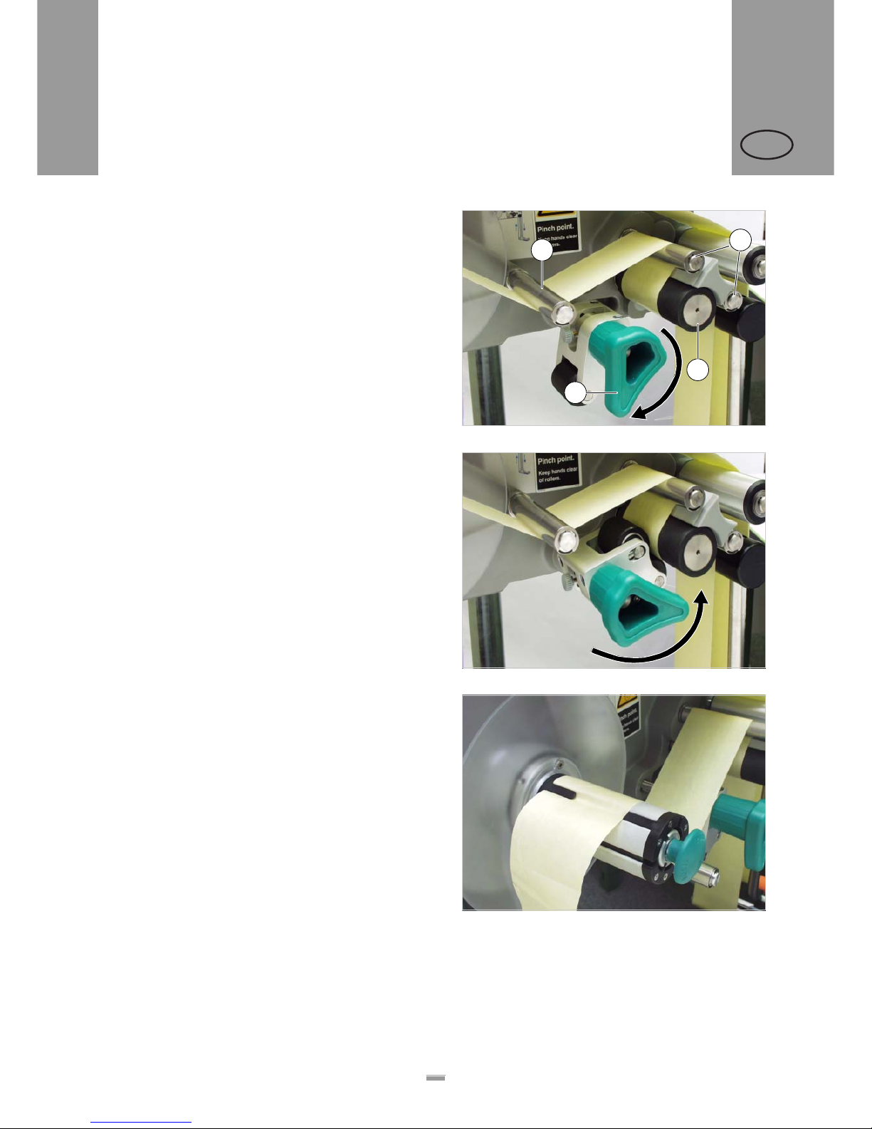
£ Open the pressure roller. To do so, rotate the lever
[42D] in a clockwise direction.
£ Feed the backing paper around the deflection roller
[42B], drive roller [42C] and the dancer arm [42A].
£ Close the pressure roller. To do so, rotate the lever
until it snaps in noticeably.
Fastening the label roll to the rewinder
£ Clamp the backing paper to the rewinder as shown
and tighten it [44].
£ Manually rotate the rewinder by one turn.
[42] Open the pressure roller.
[43] Close the pressure roller.
C
D
B
A
[44] Fastening the backing paper to the rewinder.
Page 42
42
3BEFORE OPERATION
3.3 MECHANICAL SETTINGS
ALS
20x
256
GB
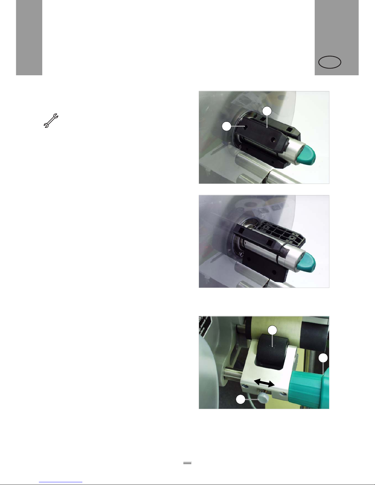
3.3.1 Adjusting the unwinder’s core
diameter
Tool:
– 3 mm hexagon (Allen) screwdriver
The unwinder can be adjusted with core adapters [45B]
to fit the inner diameter of the label roll. The adapters
must be fitted and dismantled in different ways
depending on this diameter:
– 38.1mm (1”) core
£ Unscrew the screws [45A] (2 for each adapter) and
remove the adapters.
– 76.2mm (3”) core
£ Screw on the adapters, as is shown in Figure [45].
– 101.6 mm (4”) core
£ Screw on the adapters, as is shown in Figure [46].
3.3.2 Positioning the pressure roller
£ Open the pressure roller [47B]. To do so, rotate the
lever [47C] until the roller snaps up.
£ Release thumb screw [47A].
£ Align the pressu re rolle r ove r the ba ckin g pap er so
that it is centred.
£ Close the pressure roller.
£ Screw the thumb screw tight.
[45] Core adapter positions for a core diameter of 76.2mm.
[46] Core adapter positions for a core diameter of 101.6mm.
A
B
[47] Setting the position of the pressure roller (B).
B
C
A
3.3 MECHANICAL SETTINGS
Page 43
43
3BEFORE OPERATION
3.3 MECHANICAL SETTINGS
ALS
20x
256
GB
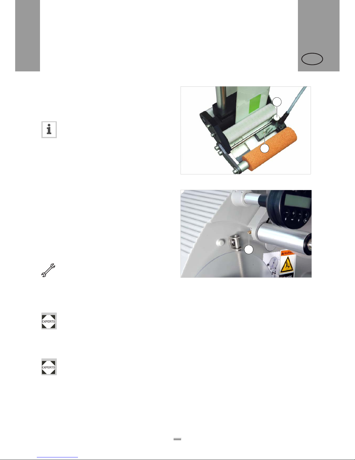
3.3.3 Positioning the label sensor
£ Release the thumb screw.
£ Position the sensor along the axle in such a way as
to allow it to register the spaces between the labels.
The LED [48A] lights up when the sensor is
positioned over a label.
3.3.4 Setting the dancer arm
restoring force
The unwinder dancer arm is preset in a way, that a wide
range of label materials can be processed whithout having to change the dancer arms restoring force.
Even so, very narrow label material can under certain
circumstances tear off or expand in a way which results
in poor labelling precision. In those cases, the restoring
force must be decreased.
Tool: 2.5mm hex socket screwdriver
£ Turn the adjusting screw [49A] on the dancer arm
left to increase restoring force.
£ Turn the adjusting screw [49A] on the dancer arm
right to decrease restoring force.
A service technician can restore the factory setting, see service manual chap. 9.4.3 section
„Adjusting restoring force of dancer arm“.
If the problem still occurs, although the restoring force
is already set to a minimum, there is the option of building in some weaker springs.
The springs must be built in by a qualified service technician. Instructions can be found in the
service manual, chap. 9.4.3 section "Replacing
dancer arm springs", „Narrow label kit“.
[48] Label sensor from Wenglor, model OPT242-P800
B
A
[49] Setting screw (A) at the unwinder dancer arm.
A
Page 44
44
4OPERATION
4.1 START-UP AND SHUTDOWN
ALS
20x
256
GB
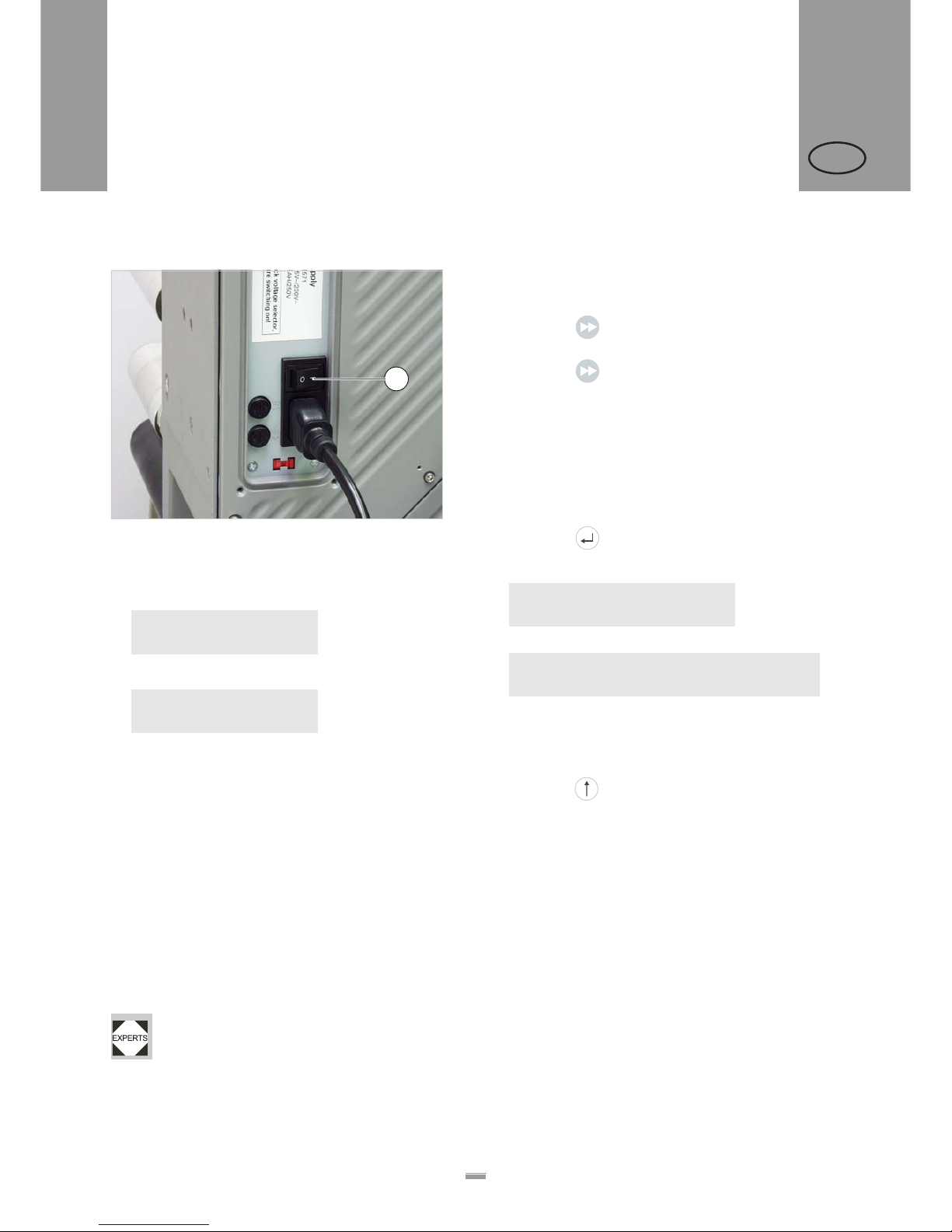
4.1.1 Turning on the unit
[50] Main switch (A) of the ALS 20x
£ Set the main switch [50A] of the unit to ‘I’ (On).
– The following messages are displayed during the
start process:
(machine type and firmware version)
– Once switched on, the ALS20x is in dispensing
mode, see section “Dispensing mode” on page 26.
4.1.2 Starting label dispensing
Dispensing with a product sensor
Once switched on, the ALS20x is in dispensing mode;
this means that triggering the product sensor will cause
a label to be dispensed.
Prerequisites:
– The label length must be specified.
– The product sensor must be connected.
– The sensors must be configured correctly
(PNP/NPN).
Dispensing without a product sensor
It is also possible to trigger the dispensing process
without a product sensor:
– The machine is in dispensing mode:
£ Press the button.
– The machine is in configuration mode:
£ Press the button briefly (less than two
seconds).
4.1.3 Stopping/Continuing the
dispensing process
– The machine is in dispensing mode.
Stopping the dispensing:
£ Press the button.
– The dispenser stops.
– One of the two texts appears:
or
1) Second line = scroll text.
Continuing the dispensing:
£ If the lower text is displayed: Remove the label from
the applicator.
£ Press the button.
ALS204 RH
V 1.34
ONLINE
Label 0
A
ONLINE
Stopped. press
Ç key to start.
1
ONLINE
Stopped. remove label. press
Ç key to start.
1
4 OPERATION
4.1 START-UP AND SHUTDOWN
Page 45
45
4OPERATION
4.2 CONFIGURATION AND MONITORING
ALS
20x
256
GB
4.2.1 Function menu settings
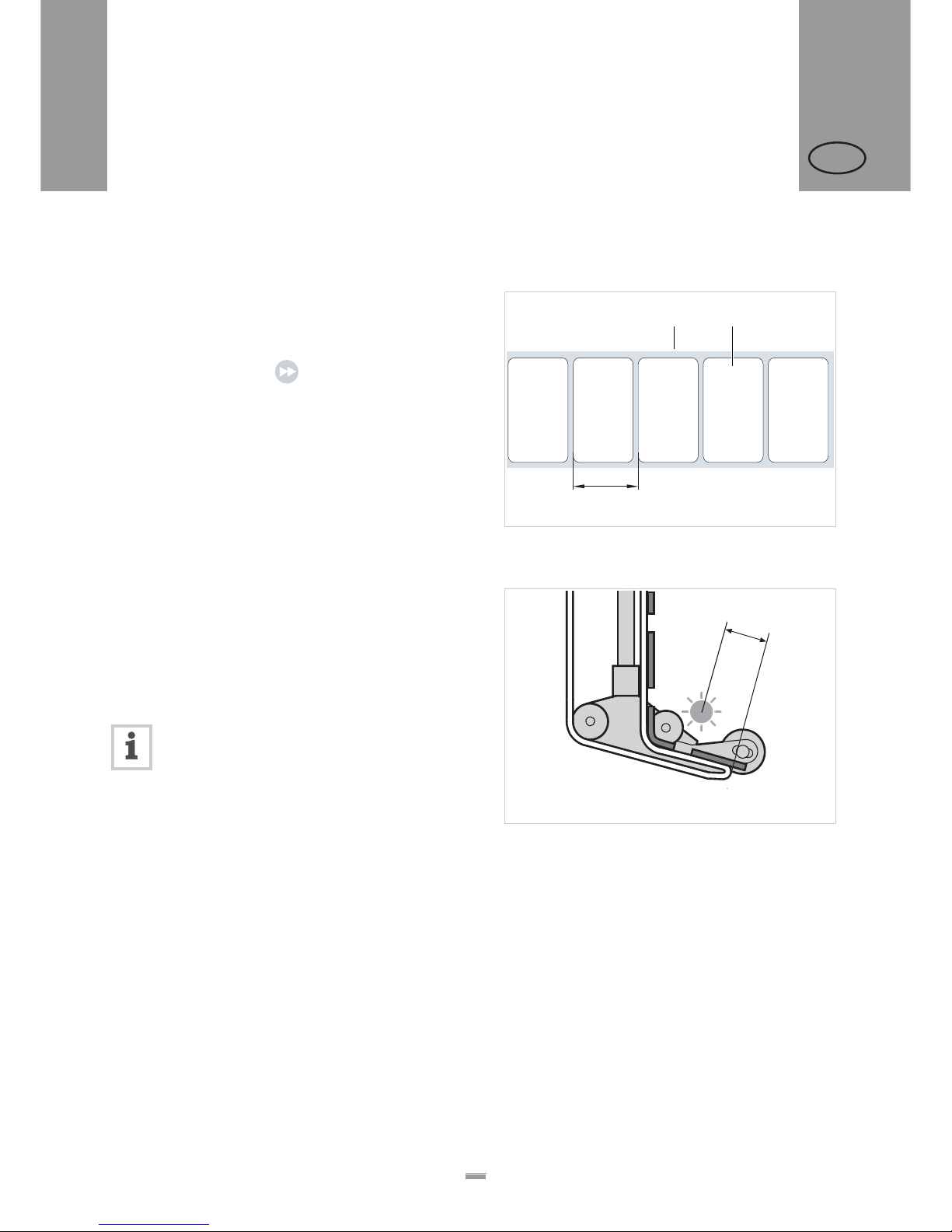
Label pitch
£ Switch to configuration mode
Calibrating the label pitch automatically:
£ Hold down the button for a while (longer than
two seconds).
Or: Enter the label pitch manually:
£ Measure the label pitch [51C].
£ Call the LABEL SETUP > Label pitch function.
£ Enter the measured value in millimetres.
Label stop position
Prerequisites:
– The label length must be specified.
The next label to be dispensed waits in the label stop
position. Here it is useful if the label protrudes over the
dispensing edge a little [52].
ALS20x/ALS256 labellers are pre-configured
for use with the supplied label sensor. If this
sensor is employed, the label stop position
setting will only require minimal correction.
Correcting the default setting:
£ Call the LABEL SETUP > Lab. stop offset function.
£ Increase the value to increase the overhang or
lower the value to reduce the overhang.
The value ‘0’ will cause the label to stop with its front
edge directly under the label sensor.
The front edge of the next label to be dispensed sh ould
be flush with the dispensing edge:
£ Enter the distance [52A] between the label sensor
and the dispensing edge.
The front edge of the label to be dispensed should
overhang:
£ Add the length of the overhang to the distance
between the label sensor and the dispensing edge.
[51] A Label web
B Label
C Label pitch
AB
C
[52] Label stop position (A)
A
4.2 CONFIGURATION AND MONITORING
Page 46
46
4OPERATION
4.2 CONFIGURATION AND MONITORING
ALS
20x
256
GB
Dispensing speed
You can set the dispensing speed to a fixed value or
you can configure it to automatically adjust to the speed
of the conveyor belt (speed adaption). The second
option requires you to connect a rotary encoder that
measures and relays the conveyor speed to the
dispenser.
Configuring a fixed value:
£ Use the two left buttons to set the speed in
dispensing mode (online settings) (see “Online
settings” on page 27).
Or use the function menu settings:
£ Call the LABEL SETUP > Dispense speed function and
set the speed you require.
Configuring speed adaption:
£ Turn the function on by setting MACHINE SETUP >
Speed Adaption to ‘Yes’.
£ Set MACHINE SETUP > Encoder Resol. and
MACHINE SETUP > Encoder Diameter as
appropriate for the employed rotary
encoder.
– See the service manual for information on suitable
rotary encoders.
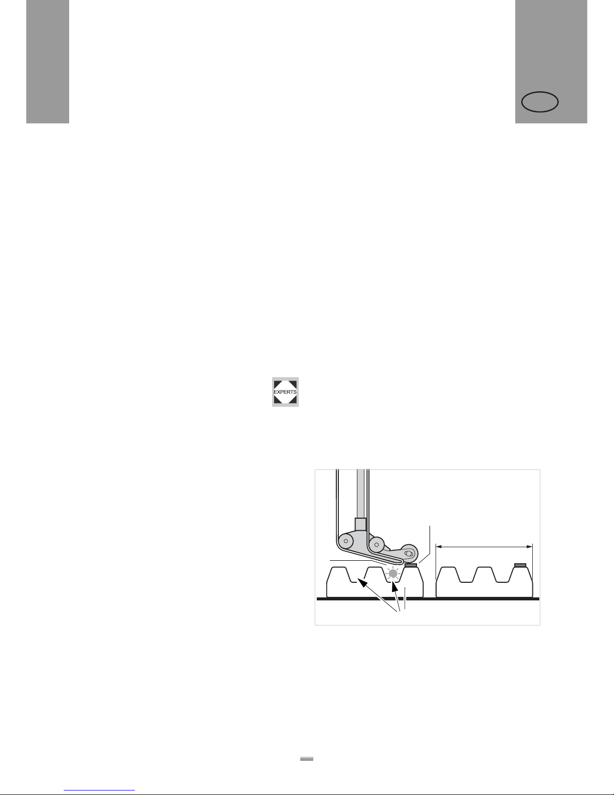
Suppressing start signals
A start signal can be prematurely triggered by the
shape of the product or reflective surfaces, what can
cause erroneous labelling. In case of a product causing
unwanted additional start signals while the product
passes the dispensing edge, those signals can be
suppressed by setting function LABEL SETUP >
Product length to the product length.
Example [53]:
If the product [D] reaches the product sensor [C], a start
signal is sent and the machine dispenses a label. The
recesses in the product trigger additional start signals;
the product would be labelled several times. With the
product length [A] set in the LABEL SETUP > Product length
function, the machine ignores all start signals until the
product has passed the dispensing edge.
[53] A Product length
B Label
C Product sensor
D Product with recesses (arrows)
A
D
C
B
Page 47
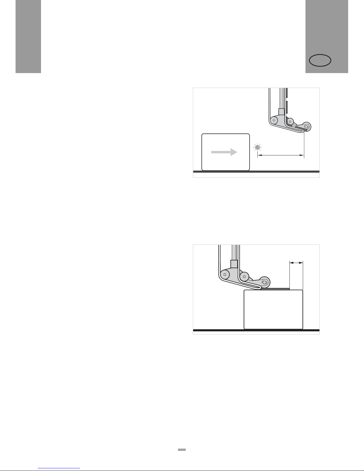
47
4OPERATION
4.2 CONFIGURATION AND MONITORING
ALS
20x
256
GB
Label position on the product
Prerequisites:
– The label length must be specified.
– The label stop position must be set.
Configuration in dispensing mode:
£ Use the two right buttons to set the start offset (see
“Online settings” on page 27).
Or use the function menu settings:
£ Call the LABEL SETUP > Start Offset fu nction and set the
start offset.
– The label should be flush with the front edge of the
product:
£ Enter the distance between the product sensor and
the dispensing edge [54A].
– The label should be stuc k at a dist an ce from th e
front edge of the product:
£ Increase the start offset by the distance [55A] to the
product’s front edge.
[54] Distance between the product sensor (left) and the
dispensing edge (right).
A
[55] Distance (A) between the label and the product’s front
A
Page 48
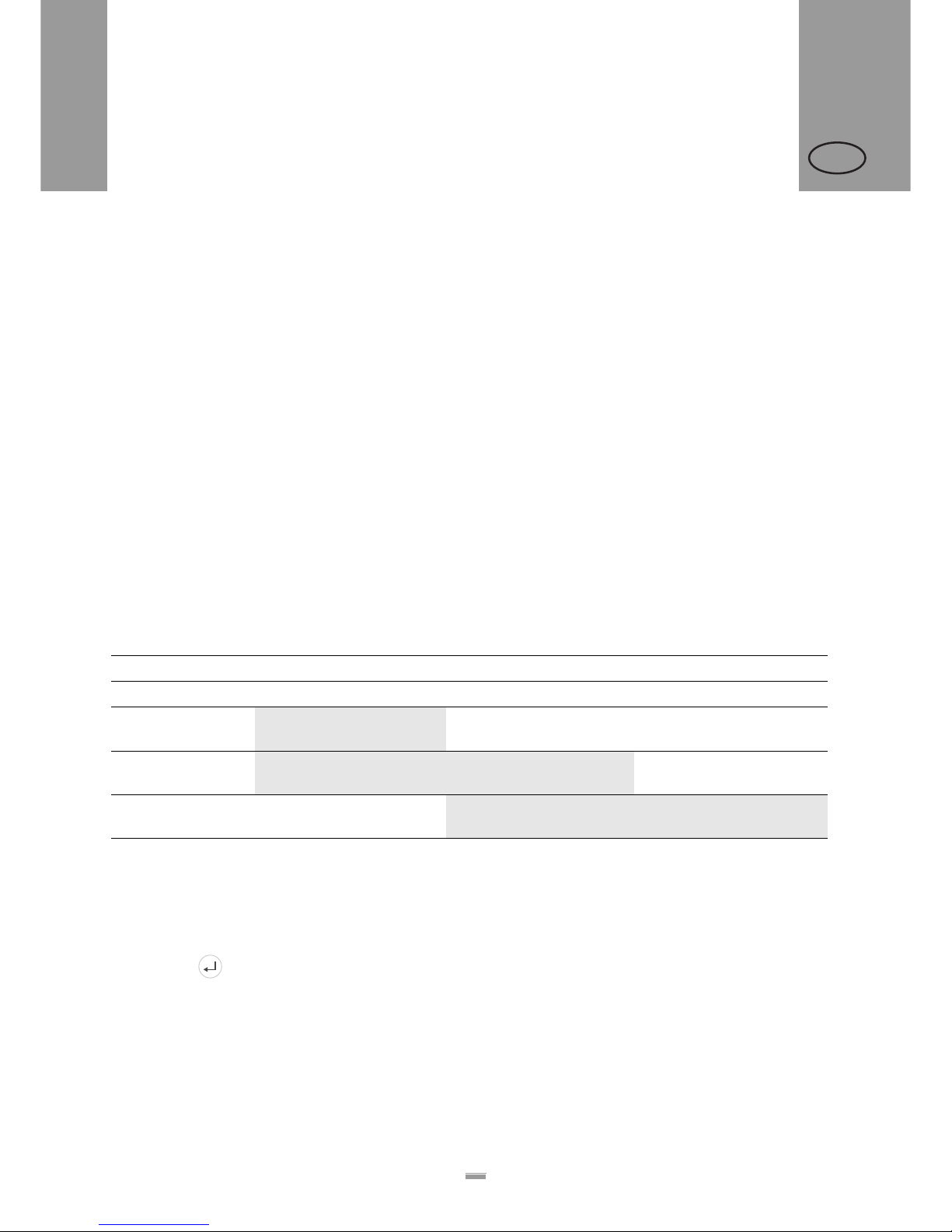
48
4OPERATION
4.2 CONFIGURATION AND MONITORING
ALS
20x
256
GB
4.2.2 Monitoring functions
While in dispensing mode, an electronic controller
monitors the following functions:
Material end / Roll diameter
(OD = outer diameter)
To enable a quick renewal of the material roll, the
machine can alarm the operator before the end of the
material roll is reached. This provides the OD-control,
which is available in two versions:
– Internal OD-control
The machine control elaborates the signals coming
from two sensors, which are integrated into the
material unwinder.
– External OD-control (accessory)
A light barrier attached to the material unwinder is
triggered, if the roll OD falls below a certain value.
Depending on the configuration and setting of the
machine, different messages appear in case of material
end or the roll diameter falling below the critical value:
[56] Messages for monitoring label stock.
1) If MACHINE SETUP > Material end err = „On“
2) If MACHINE SETUP > OD sensor mode = „Warning“
3) If MACHINE SETUP > OD sensor mode = „Error“
If a warning occurs:
– Labelling operation is continued.
£ Press the button, to delete the warning.
£ Prepare for inserting a new material roll.
Material end Critical OD reached
Error message Warning Error message
No OD-control Status num: 5001
No gap found
none none
Internal OD-control
Status num: 5002
1)
Material end
ONLINE
Material low
none
External OD-control none
ONLINE
2)
OD sensor warn.
Status num: 5065
3)
OD material end
Page 49

49
4OPERATION
4.2 CONFIGURATION AND MONITORING
ALS
20x
256
GB
If an error message occurs:
– The machine stops.
£ Press the button to delete the message.
£ Remove the rewound backing paper.
£ Insert a new material roll (see “Inserting a label roll”
on page 37).
Missing labels
A label missing from the label roll does not normally
affect the dispensing operation, because the label feed
continues until a label’s edge passes under the label
sensor.
Nonetheless, it can be important that missing labels are
reported. By configuring the function LABEL SETUP >
Miss. label tol., you can specify whether an error message
is triggered after one or several missing labels.
Material tear
If the material path tears, one of these two messages
appears:
– Which message appears depends on where the
material path is torn.
– The machine stops.
£ Press the button.
Status num: 5002
Material end
Status num: 5140
Rewinder control
Page 50
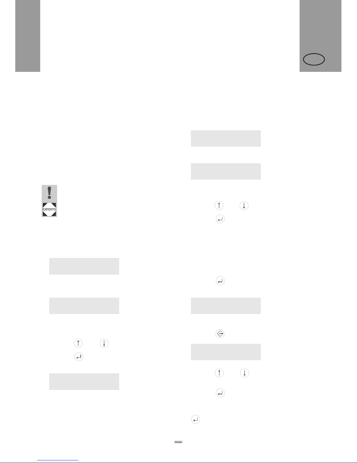
50
4OPERATION
4.3 USING PRODUCT PROFILES
ALS
20x
256
GB
4.3.1 What are product profiles?
Product profiles are memory locations that can store all
the settings for the machine controls. For recurring
production jobs, they allow you to quickly set the
machine to the respective product.
– Number of memory locations: 16
– The memory locations are numbered. In addition,
you can also enter a text identifier for each memory
location (with a maximum of 9 alphanumeric
characters).
4.3.2 Loading a product profile
CAUTION!
Incorrect settings may lead to production
problems and damage both the unit and the
equipment.
£ Only staff who are qualified and specially
trained should set up product databases.
£ Call the LABEL SETUP > Load prod. profil function.
– The following message appears when no memory
location is occupied:
– Only occupied memory locations are displayed.
– When memory locations are occupied, the memory
location that was loaded last is displayed first:
Above example: The profile with the ‘xxxxxx’ text
identifier has been stored at the first memory
location.
£ Press the or the button until the profile you
require appears.
£ Press the button to load the profile.
– The unit restarts afterwards.
– Display after the restart:
(in dispensing mode, ‘ONLINE’ is replaced by the
current profile name).
4.3.3 Storing a product profile
Selecting the memory location
£ Call the MACHINE SETUP > Store prod.prof. function.
– Display shown when all memory locations are
unoccupied:
– When memory locations are already occupied, the
memory location that was last active is displayed:
– A ‘*’ occurring after the memory location number
indicates that the memory location is already
occupied (here by the ‘customer_xyz’ profile) .
£ Press the or the button until you retrieve the
memory location you require (1–16).
£ Press the button to activate the memory
location.
– The profile name flashes, and you can now replace
the name using any text you choose.
Entering profile names
Accepting the profile name ‘Product 1’ without
changing it:
£ Press the button twice.
– The profile is saved.
– Display:
Changing a profile name:
£ Press the button.
– Display:
– The underscore marks the active position.
£ Press the or the button to scroll through the
available characters until the character you require
appears.
£ Press the button to accept the character.
– The underscore jumps to the next character.
£ Enter the next character in the same way.
£ When you have entered the last character, press the
button.
Load prod. profil
No setup avail.
Load prod. profil
Prof 1 xxxxxx
Prof 1 xxxxxx
Label 0
Store prod.prof.
Prof 1 Product 1
Store prod.prof.
Prof 5*customer_xyz
Store prod.prof.
Storing…
Store prod.prof.
Prof x _
4.3 USING PRODUCT PROFILES
Page 51

51
4OPERATION
4.3 USING PRODUCT PROFILES
ALS
20x
256
GB
– The profile is saved.
– Display:
– The product profile has now been saved.
4.3.4 Deleting a product profile
£ Call the MACHINE SETUP > Del. prod.profil function.
– The memory location that was active last is
displayed.
£ Press the or the button until you retrieve the
memory location you require (1–16).
£ Press the button to delete the memory location:
– Display:
– The product profile has now been deleted.
Store prod.prof.
Storing…
Del prod.profil
Clearing…
Page 52
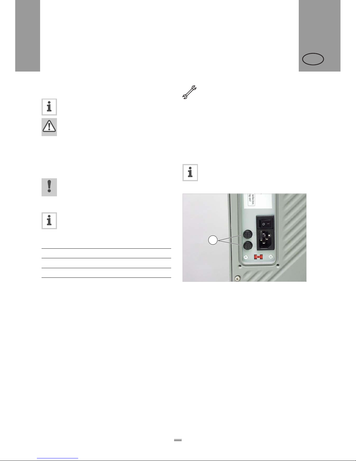
52
5AFTER OPERATION
5.1 MAINTENANCE AND CLEANING
ALS
20x
256
GB
5.1.1 Replacing fuses
This section counts only for ALS20X. The fuses at the ALS256 cannot be replaced.
WARNING!
The machine operates using mains voltage!
Touching live electrical parts may exp ose
you to hazardous electrical currents and
may lead to burns.
£ Make sure that the machine is switched
off and the power cable is unplugged
before removing the fuse insert.
CAUTION!
Risk of fire, if a wrong fuse type is inserted.
£ Only replace fuses with the type and
rating specified in this manual.
The F1 and F2 fuses protect the primary side of
the transformer. At any given time, only one of
the two fuses is active. Which fuse is active
depends on the switch setting of the voltage
selector switch.
[57] Relation between the switch setting of the voltage selector
switch and the active fuse.
The CPU board and sensors are protected by a
separate fuse in the switching power supply that
must/may never be replaced.
If either of the two fuses is not working properly, only
the drive motors are affected; the display and sensors
continue to operate as normal.
Tool: Screwdriver
£ Turn off the unit. Unplug the power cable.
£ Rotate the fuse holder a few degrees anticlockwise.
– The fuse holder pops up.
£ Take the fuse out of the fuse holder.
£ Replace defective fuse.
£ Replace the fuse holder and rotate it clockwise,
while applying light pressure, until the slot is
vertically positioned.
Required fuse type:
– T5AH 250V
[58] Fuse holder (A) of the ALS 20x.
Active fuse Mains voltage Switch setting
F1 230V 230
F2 110V 115
A
5 AFTER OPERATION
5.1 MAINTENANCE AND CLEANING
Page 53
53
5AFTER OPERATION
5.1 MAINTENANCE AND CLEANING
ALS
20x
256
GB
5.1.2 Cleaning agents
Cleaning agents for rubber rollers:
– Roller cleaner, order number 98925.
If other cleaning agents are used, there is a
chance the rubber may corrode.
Cleaning agents for metal deflection rollers:
– Cleaning solvent, alcohol-based solvent,
isopropyl alcohol, spray for removing labels
Cleaning the unit’s housing:
– Commercially available neutral cleaning
liquid
WARNING!
Cleaning solvent, alcohol-based solvent an d
isopropyl alcohol are highly inflammable!
£ Keep the cleaning agents, as well as any
used cleaning cloths, away from open
flames and other sources of ignition.
£ Do not smoke.
£ Observe the safety instructions on the
container.
CAUTION!
Unsuitable cleaning agents can cau s e
considerable damage to the unit!
£ Do not use any cleaning agent that could
damage or destroy the resin surface,
labelling, display, nameplates, electrical
components, etc. Observe the
instructions of the cleaning agent
manufacturer.
£ Do not use any abrasive or
plastic-corroding cleaning agents.
£ Do not use any acidic or alkaline
solutions.
Page 54
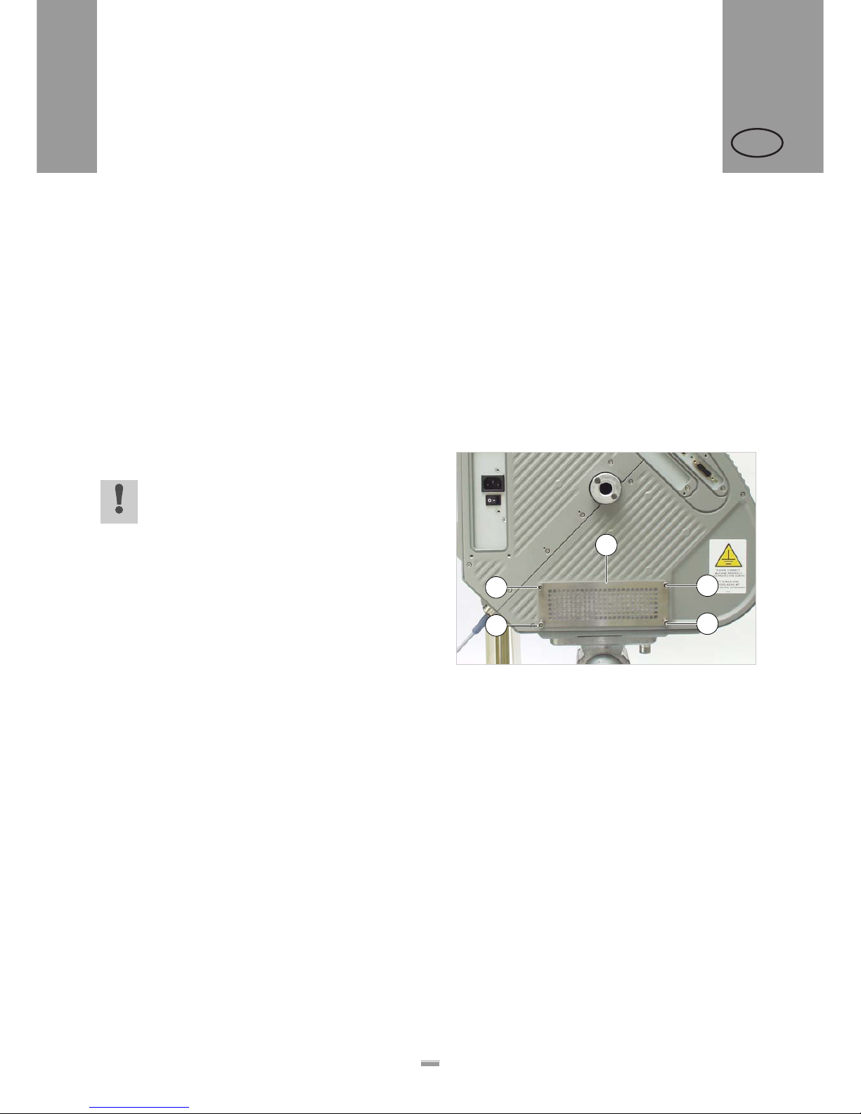
54
5AFTER OPERATION
5.1 MAINTENANCE AND CLEANING
ALS
20x
256
GB
5.1.3 Regular maintenance
The label dispenser is designed to be
maintenance-free. However, you should service the
unit regularly in order to ensure reliable long-term
operating results.
Removing paper debris
Depending on operating conditions, you should
perform the following at least once a week:
£ Wipe the paper residue from the rollers and edges.
£ Clean the sensor lenses with a soft brush or cloth.
Renewal of the dust filter liner (ALS256)
CAUTION!
An exhausted filter liner can cause the
machine to overheat and to break down.
£ Replace the filter liner regularly, at least
in monthly intervals.
In case of overheating the machine, the error message
„5026 MotorProtect CPU“ appears, see “List of error
messages” on page 56.
£ Screw out the four thumb screws [59A]. Remove the
filter cover [59B].
£ Replace filter liner (article no. A8697).
£ Assemble the filter cover and fix it using the thumb
screws.
[59] Dust filter at an ALS256.
A Thumb screws
B Filter cover
A
A
A
A
B
Page 55
55
6OPERATIONAL FAILURES
6.1 STATUS MESSAGES
ALS
20x
256
GB
6.1.1 Types of status messages
Error messages
When an error occurs, the machine stops immediately
and displays an error message on the control panel.
Error messages are displayed as follows:
[60] An example of an error message:
5144 = status number; this number makes it easier to identify the
message.
‘Rewinder init’ = status text; a brief description of the error.
Error messages that are not described here may only
be resolved by a qualified service technician.
When an error occurs that is not described here:
£ Press the button to delete the message.
£ Switch the device off, wait 30 seconds and then
switch it on again.
If the error reoccurs:
£ Request a service technician.
Error messages that are not mentioned here
are described in the service manual.
Warnings
Warnings indicate less severe status than error
messages. The labelling is not interrupted by a
warning.
Warning format:
[61] Example of a warning:
„Materialend warn.“ = Warning text; a short description of what
has caused the warning.
Setting back a warning:
£ Press the key (works earliest with firmware
versions > 1.10).
6.1.2 List of warnings
Status num: 5144
Rewinder init
ONLINE
Materialend warn.
Displayed text Meaning
Produktstartwarn New start signal during the
dispensing operation.
Or:
Several missing labels on the
web, which can not be
compensated.
APSF speed warn. The conveyor speed exceeded
the max. speed of the
dispenser.
OD Sensorwarning External OD-control:
Critical material roll diameter is
reached.
Material low Internal OD-control:
Critical material roll diameter is
reached.
Toomany products Too many products between
sensor and dispensing edge
(max. 8 products are allowed).
6 OPERAT IONAL FAILURES
6.1 STATUS MESSAGES
Page 56

56
6OPERATIONAL FAILURES
6.1 STATUS MESSAGES
ALS
20x
256
GB
6.1.3 List of error messages
Status Status text Cause Action to take
5000 Bus device – Device at I2C Bus cannot be
contacted.
– In most cases, this message appears
as the first in a series of two or three
messages which narrow down the
error more precisely.
£ Delete the mess ag e by pre ssin g the
-key.
£ Switch the machine off, wait 30
seconds and switch it back on.
£ If the error message
appears
repeatedly, call in a servicing
technician.
5001 No gap found – Material end, if no outer diameter
(OD) control is activated.
– The maximum limit for missing labels
was exceeded (LABEL SETUP >
Miss. label tol.).
– The machine is not correctly set for
the type of label (MACHINESETUP >
Light sens. type ).
– Label length is not correctly set
(LABEL SETUP > Label pitch).
– Photoelect ric lab e l sens or is dirty.
– Photoelectric label sensor is
incorrectly positioned.
– Photoelec t ric labe l se ns or is not
connected correctly.
– Photoelectric label sensor is
defective.
– Rotary encoder is not adjusted
correctly.
£ Check the points listed above and
correct if necessary.
£ Press the key to confirm the
error message.
5002 Material end – Material end (if the internal OD-
control is activated).
£ Insert new label roll.
£
5026 Moto rProtect CPU – (ALS 256) Dust filter liner exhausted.
This leads to overheating the
machine.
– (ALS 20X) Voltage selection switch
set faulty.
– There are some more possible
causes, which require a qualified
service technician to cure.
£ Renew the dust filter liner. Let the
machine cool down
£ Check setting of th e vo ltage
selectioin switch.
£ Switch the machine off, wait 30
seconds and switch it back on.
£ If none of the above listed actions is
successful, search for technical
assistance.
[62] List of error messages
Page 57
57
6OPERATIONAL FAILURES
6.1 STATUS MESSAGES
ALS
20x
256
GB
5140 Rewinder control Rewinder control
During problem-free operation,
the rewind unit dancer arm only
moves a minimal distance
around the "control position".
This is the position the dancer
arm takes up after initialisation
of the machine.
– Any force applied that moves the
dancer arm from its control position.
Example: The feed motor is blocked;
the backing paper is not conveyed
quickly enough; as a result the
dancer arm is pulled upwards.
Example: The backing paper is torn;
the dancer arm springs downwards.
£ Press the key.
– This reinitialises the dancer arm
control; the dancer arm moves back
into the control position.
5143 Rewinder Stop – This message appears when the
dancer arm was held against its
upper stop for more than two
seconds.
Effect:
Power to the rewinder motor is
switched off, so that the rewinder can
be turned easily by hand.
This effect is helpful when
installing a new label roll,
because the rewinder can be
turned easily.
£ Press the key to confirm the
error message.
5145 Rewinder full This error can only occur if the
end of a new label roll was glued
on to backing paper that had
already been wound onto the
rewinder.
– The maximum permitted diameter
(205mm) for the rewinder roll has
been reached.
£ Remove the rewound backing paper
£ Press the key to confirm the
error message.
Status Status text Cause Action to take
[62] List of error messages
Page 58
58
6OPERATIONAL FAILURES
6.1 STATUS MESSAGES
ALS
20x
256
GB
5147 Tandemsynch. Init This message can only appear
during tandem operation.
– Communication between the master
and slave machines is not
functioning.
£ Check, if the slave machine had
been switched on before the master
machine - if not, repeat the switching
on in the correct order (first slave,
then master).
£ Check, if both machines are
connected with the tandem interface
cable - if not, connect them. For
detailed information, contact a
service technician.
5152 Winding direct. The backing paper end is not correctly
attached to the rewinder mandrel.
£ Attach the backing paper web to the
rewinding mandrel as described in
chap. “Fastening the label roll to the
rewinder” auf Seite 41.
5200 Home position This message may appear when
operating the applicator. The
applicator did not reach its home
position (upper end position)
within the intended time-frame.
– Applicator operation set, but no
applicator available.
– The applicator is stuck.
– Compressed air applicator:
Compressed air supply interrupted or
switched off.
– Cable not correctly connected.
£ Set SIGNAL INTERFACE > Interface mode
to „PLC interface“.
£ Remove any obstructions
£ Check compressed air connection
and reconnect correctly if necessary.
£ Check cable and connect correctly if
necessary.
5201 Touch Down The applicator lower end position
(Touch Down) was not reached in time.
6002 New prog. vers. New firmware has been loaded. This is a
message from the labeller that new
firmware is available.
£ Press the Online button to confirm.
– All parameters are reset to their
factory settings.
6030 New Parameters New firmware was loaded with the result
that new functions have been added to
the menu.
£ Press the Online button to confirm.
– Automatic reset is performed.
– All parameters are reset to their
factory settings.
6207 No file card No compact flash card was found. £ Check whether a compact flash card
is connected. If the compact flash
card was not connected until after the
machine was switched on: Switch the
machine off and back on again.
Status Status text Cause Action to take
[62] List of error messages
Page 59

59
6OPERATIONAL FAILURES
6.1 STATUS MESSAGES
ALS
20x
256
GB
9022 No network link This status message can only appear
when Ethernet address assignment is
set to DHCP (INTERFACE PARA >
NETWORK PARAM.> IP Addressassign). The
cause is almost invariably an incorrectly
plugged-in network connector.
£ Check whether the network
connector is plugged in correctly,
correct if necessary.
Status Status text Cause Action to take
[62] List of error messages
Page 60
60
7APPENDIX
7.1 EC DECLARATION OF CONFORMITY
ALS
20x
256
GB
We,
Avery Dennison Deutschland GmbH
Ohmstrasse 3
85386 Eching, Germany
herewith assert that we have designed and built th e de vice described in the following to conform with the basic
safety and health requirements of the relevant EU directives.
Eching, 19. March 2009
Name of the devices: ALS 204, ALS 206, ALS 256
Device type: Label dispenser
Serial number: Consists of a sequential number (five-digit) +
date code (YYMM) +
ending (device name): –ALS204, –ALS206 or –ALS256
(Example: 040060309–ALS204)
Relevant EU directives: 2004/108/EC (EMC Directive)
2006/95/EC (Low Voltage Directive)
Other applicable, harmonised
norms, in particular:
EN 60950-1/A11:2004 (Information technology eq uipment safety)
EN 55022:2006 class A (Information technology equipment - Radio
disturbance characteristics - Limits and methods of measurement )
EN 61000–6-2: 2005 (Immunity standard for industrial environments)
EN 61000-3-2: 2006 (Limits for harmonic current emissions)
EN 61000-3-3/A2:2005 (Limitation of voltage changes, voltage
fluctuations and flicker)
Year of first CE marking: ALS204, ALS206: 2006
ALS256: 2007
Markus Roderer (General Manager)
7 APPENDIX
7.1 EC DECLARATION OF CONFORMITY
Page 61

Page 62
Avery Dennison Deutschland GmbH
Ohmstraße 3
85386 Eching
Germany
Telephone: +49-8165-925-0
http://www.machines.averydennison.com
 Loading...