

Page 1

ALS
104
USER MANUAL
Label Dispenser
Edition 5 4/2010
Page 2

Page 3

3
CONTENTS
ALS
104
GB
1 Please note
1.1 General notes
1.1.1 Validity and binding effect of this manual . . . . 5
Contents . . . . . . . . . . . . . . . . . . . . . . . . . . . . . . .5
Technical status . . . . . . . . . . . . . . . . . . . . . . . . .5
Copyright. . . . . . . . . . . . . . . . . . . . . . . . . . . . . . .5
Manufacturer. . . . . . . . . . . . . . . . . . . . . . . . . . . .5
1.1.2 Illustrations and descriptions. . . . . . . . . . . . . . 6
Signs and symbols . . . . . . . . . . . . . . . . . . . . . . . 6
Dangers and risk notes . . . . . . . . . . . . . . . . . . . .6
Figures . . . . . . . . . . . . . . . . . . . . . . . . . . . . . . . .6
Button symbols . . . . . . . . . . . . . . . . . . . . . . . . . .6
Functions. . . . . . . . . . . . . . . . . . . . . . . . . . . . . . .6
Supplementary information . . . . . . . . . . . . . . . . .6
1.2 Safety instructions
1.2.1 Information and qualifications. . . . . . . . . . . . . 7
Follow the instructions. . . . . . . . . . . . . . . . . . . . .7
Keep the product information at hand. . . . . . . . . 7
Ensure the required qualifications are met . . . . .7
1.2.2 Operational safety of the unit . . . . . . . . . . . . . 8
Proper usage. . . . . . . . . . . . . . . . . . . . . . . . . . . .8
Protection against injuries by electrical current. .8
Protection against injuries by mechanical action.9
Protection against injuries by chemicals . . . . . . .9
1.2.3 Before beginning production. . . . . . . . . . . . . 10
Due diligence of the operating company and the
service technician . . . . . . . . . . . . . . . . . . . . . . .10
Due diligence of the user. . . . . . . . . . . . . . . . . .10
1.2.4 Safety notes on the unit . . . . . . . . . . . . . . . . 11
2 Product description
2.1 Overview
2.1.1 Components . . . . . . . . . . . . . . . . . . . . . . . . . 12
2.1.2 Control panel. . . . . . . . . . . . . . . . . . . . . . . . . 14
Operating LED. . . . . . . . . . . . . . . . . . . . . . . . . .14
Status LED . . . . . . . . . . . . . . . . . . . . . . . . . . . .14
LCD display. . . . . . . . . . . . . . . . . . . . . . . . . . . .14
Buttons . . . . . . . . . . . . . . . . . . . . . . . . . . . . . . .14
2.1.3 Connection arrangement . . . . . . . . . . . . . . . 15
Connections on the back of the device . . . . . . .15
Sensor connections. . . . . . . . . . . . . . . . . . . . . .15
2.1.4 Mode of operation. . . . . . . . . . . . . . . . . . . . . 16
2.1.5 Technical specifications . . . . . . . . . . . . . . . . 17
Characteristics. . . . . . . . . . . . . . . . . . . . . . . . . .17
Labels . . . . . . . . . . . . . . . . . . . . . . . . . . . . . . . .17
Label sensor . . . . . . . . . . . . . . . . . . . . . . . . . . .17
Power supply. . . . . . . . . . . . . . . . . . . . . . . . . . .17
Electronics. . . . . . . . . . . . . . . . . . . . . . . . . . . . .17
Internal Interfaces . . . . . . . . . . . . . . . . . . . . . . .18
Status messages, test functions . . . . . . . . . . . .18
Dimensions . . . . . . . . . . . . . . . . . . . . . . . . . . . .18
Environmental conditions . . . . . . . . . . . . . . . . .18
Integration . . . . . . . . . . . . . . . . . . . . . . . . . . . . .18
Certificates. . . . . . . . . . . . . . . . . . . . . . . . . . . . .18
2.1.6 Design models . . . . . . . . . . . . . . . . . . . . . . . 19
Right-handed version . . . . . . . . . . . . . . . . . . . .19
Left-handed version. . . . . . . . . . . . . . . . . . . . . .19
2.2 Options
External control panel . . . . . . . . . . . . . . . . . . . .20
Fixed dispensing edge. . . . . . . . . . . . . . . . . . . .20
Swivelling dispensing edge . . . . . . . . . . . . . . . .20
Spring-loaded dispensing edge. . . . . . . . . . . . .20
Pneumatic dispensing edge . . . . . . . . . . . . . . .21
V-shape dispensing edge . . . . . . . . . . . . . . . . .21
Adjustable dispensing edge holder . . . . . . . . . .21
Outer Diameter control sensor . . . . . . . . . . . . .22
Dust/Splash guard. . . . . . . . . . . . . . . . . . . . . . .22
Additional material guide disk . . . . . . . . . . . . . .22
Printer . . . . . . . . . . . . . . . . . . . . . . . . . . . . . . . .23
Narrow label spring kit. . . . . . . . . . . . . . . . . . . .23
2.3 Operating modes
2.3.1 Dispensing mode . . . . . . . . . . . . . . . . . . . . . 24
Dispensing speed . . . . . . . . . . . . . . . . . . . . . . .24
Start offset. . . . . . . . . . . . . . . . . . . . . . . . . . . . .24
Dispensing manually . . . . . . . . . . . . . . . . . . . . .24
2.3.2 Configuration mode . . . . . . . . . . . . . . . . . . . 25
Function of the double-arrow button . . . . . . . . .25
Menus . . . . . . . . . . . . . . . . . . . . . . . . . . . . . . . .25
Functions. . . . . . . . . . . . . . . . . . . . . . . . . . . . . .26
2.3.3 Function overview . . . . . . . . . . . . . . . . . . . . 26
2.3.4 Function descriptions. . . . . . . . . . . . . . . . . . 27
LABEL SETUP menu . . . . . . . . . . . . . . . . . . . .27
MACHINE SETUP menu. . . . . . . . . . . . . . . . . .27
SERVICE FUNCTION menu . . . . . . . . . . . . . . .27
2.4 Inserting label material
2.4.1 Prerequisites . . . . . . . . . . . . . . . . . . . . . . . . 28
2.4.2 Inserting a label roll . . . . . . . . . . . . . . . . . . . 29
Removing spent backing paper. . . . . . . . . . . . .29
Removing glue residue . . . . . . . . . . . . . . . . . . .29
Inserting a new label roll . . . . . . . . . . . . . . . . . .29
Page 4

4
CONTENTS
ALS
104
GB
2.4.3 Threading the label web . . . . . . . . . . . . . . . . 30
Threading guide . . . . . . . . . . . . . . . . . . . . . . . .30
Threading the label roll at the dispensing edge.31
Threading the label roll onto the drive roller . . .32
Fastening the label roll to the rewinder . . . . . . .32
3 Before operation
3.1 Electrical connections
3.1.1 Power supply standard machine. . . . . . . . . . 33
Checking the power supply setting . . . . . . . . . .33
Connecting the power cable.. . . . . . . . . . . . . . .34
3.1.2 Power supply with dust/splash guard option. 34
3.1.3 Connecting sensors . . . . . . . . . . . . . . . . . . . 34
3.2 Mechanical settings
3.2.1 Adjusting the unwinder’s core diameter . . . . 35
3.2.2 Positioning the pressure roller . . . . . . . . . . . 35
3.2.3 Calibrating the label sensor . . . . . . . . . . . . . 36
3.2.4 Setting the dancer arm restoring force . . . . . 36
4 Operation
4.1 Start-up and shutdown
4.1.1 Turning on the unit . . . . . . . . . . . . . . . . . . . . 37
4.1.2 Starting label dispensing. . . . . . . . . . . . . . . . 37
Dispensing with a product sensor . . . . . . . . . . .37
Dispensing without a product sensor . . . . . . . .37
4.1.3 Stopping the dispensing process . . . . . . . . . 37
4.2 Configuration and monitoring
4.2.1 Function menu settings. . . . . . . . . . . . . . . . . 38
Label length. . . . . . . . . . . . . . . . . . . . . . . . . . . .38
Label stop position . . . . . . . . . . . . . . . . . . . . . .38
Dispensing speed . . . . . . . . . . . . . . . . . . . . . . .39
Label position on the product . . . . . . . . . . . . . .40
4.2.2 Monitoring functions . . . . . . . . . . . . . . . . . . . 41
Missing labels . . . . . . . . . . . . . . . . . . . . . . . . . .41
Recognising the end of the label roll in
advance. . . . . . . . . . . . . . . . . . . . . . . . . . . . . . .41
5 After operation
5.1 Maintenance and cleaning
5.1.1 Changing fuses . . . . . . . . . . . . . . . . . . . . . . 42
5.1.2 Cleaning agents. . . . . . . . . . . . . . . . . . . . . . 43
5.1.3 Regular maintenance. . . . . . . . . . . . . . . . . . 43
Removing paper debris . . . . . . . . . . . . . . . . . . .43
6 Operational failures
6.1 Error messages
6.1.1 Error messaging. . . . . . . . . . . . . . . . . . . . . . 44
6.1.2 List of error messages . . . . . . . . . . . . . . . . . 44
7 Appendix
7.1 EC declaration of conformity
Page 5

5
1PLEASE NOTE
1.1 GENERAL NOTES
ALS
104
GB
1.1.1 Validity and binding effect of this manual
Contents
This technical manual refers exclusively to the ALS 104
Label Dispenser. It is written for the purpose of
ensuring professional usage and calibration of the unit.
Prerequisites for the use and adjustment are the
professional installation and configuration of the unit.
For any technical questions you may have that are not
described in this manual, see:
£ The service manual of the label dispenser
or
£ Request a technician from one of our sales partners.
– Our sales representatives are available to assist
you, particularly with configuring the unit as well as
in the case of malfunctions.
Technical status
Technical status: 10/2008
Software version: 3.21 (front end), 1.84 R01 (drive)
Avery Dennison reserves the right:
– To make modifications to construction parts,
components and software, as well as to employ
comparable components in place of the parts
specified, in keeping with technical advances.
– To modify information in this document.
No commitment will be made to expand these
modifications to include any units delivered earlier.
Copyright
Avery Dennison holds all rights to this manual and its
appendices. Reproduction, reprinting or any other
types of duplication, even of portions of this manual,
may only be carried out with express written consent.
Third persons, in particular competitors, should not be
given access to the information in this manual.
Printed in Germany
Manufacturer
Avery Dennison Deutschland GmbH
Ohmstrasse 3
85386 Eching, Germany
Phone: +49-8165-925-0
Fax: +49-8165-925-231
http://www.machines.averydennison.com
1 PLEAS E NOTE
1.1 GENERAL NOTES
Page 6

6
1PLEASE NOTE
1.1 GENERAL NOTES
ALS
104
GB
1.1.2 Illustrations and descriptions
Signs and symbols
Various information types are indicated in differ en t
ways within the document in order to simplify
readability and comprehension.
Sentences starting with an arrow are instructions and
guidelines.
£ Perform the instructions one after another in the
specified order.
The following information begins with a dash:
–Lists
– Mode descriptions
– Descriptions of prior steps
– Prerequisites for following actions
Dangers and risk notes
Important directions that you must absolutely observe
are particularly emphasized:
WARNING!
A warning refers to risks that can lead to
serious injury or death! The warning
contains safety measures to protect the
relevant persons.
£ Always follow the instructions.
CAUTION!
A caution indicates risks that can lead to
property damage or injuries to persons
(minor injuries). The caution note contains
instructions for preventing dama ge s .
£ Always follow the instructions.
Figures
Texts are accompanied by figures where necessary.
Figures are indicated using figure numbers in [square
brackets]. A capital letter after a figure number, for
example [12A], refers to a specific section of the figure.
Generally, the label dispenser shown is an ALS 104
right-handed version. The left-handed version is only
shown where it is necessary to differentiate between
the two.
Button symbols
– The buttons of the control panel are depicted as
symbols.
– The symbols are depicted with a ‘+’ (PLUS SIGN)
between them if more than one button is to be
pressed. +
Functions
Functions are displayed in grey in the text with the
following structure, MENU NAME > Function name.
Supplementary information
The expert symbol indicates actions that are
only to be performed by qualified and specially
trained personnel.
The information symbol indicates notes and
recommendations, as well as additional
information.
Equipment:
– Equipment, for example lubricants or
cleaning agents
Page 7

7
1PLEASE NOTE
1.2 SAFETY INSTRUCTIONS
ALS
104
GB
1.2.1 Information and qualifications
Follow the instructions
WARNING!
Safe and efficient operation of the label
dispenser can only be guaranteed if you
observe all necessary information.
Product liability and warranty claims can
only be asserted if the unit was operated in
accordance with the directions in the
manual.
£ Before operating the unit, read the
operating instructions and all other notes
carefully.
£ Observe the additional safety and
warning notes on the label dispenser.
£ Only permit competent people to operate
and configure the label dispenser.
Keep the product information at hand
With respect to this manual:
£ It should be kept at the location where the
unit is installed and be available to the
operator.
£ It should always be legible.
£ If the unit is sold, the manual should be made
available to the new owner.
£ The safety and warning notes affixed to the
unit itself must be kept clean and legible.
Missing or damaged signs must be replaced.
Ensure the required qualifications are met
£ Ensure that only trained and authorized personnel
operate, configure and service the unit.
£ Only allow qualified and well-trained expert
personnel or service technicians to perform
configurations.
£ The responsibilities with regard to operation,
configuration and maintenance should be cl ea rly
defined and consistently maintained.
£ In addition, personnel should also be instructed on
a regular basis in matters of occupational safety and
environmental protection.
Qualification for operation
The instruction of personnel using the unit must ensure
that:
– The operating perso nnel can use the unit on their
own and safely.
– The operating personnel can remedy small
operational disruptions on their own.
£ At least two people must be instructed in the unit’s
usage.
£ Enough label material must be provided for testing
and instructional purposes.
Qualifications for configuring
The configuration of the controls requires
qualified expertise:
– Personnel configuring the unit must be
acquainted with the functionality of the label
dispenser.
– Personnel configuring the unit must be
acquainted with the modes of operation
within the facility in which the label dispenser
is integrated.
– The personnel configuring the unit must be
able to use the additional menus properly
and appropriately for specific project
requirements.
1.2 SAFETY INSTRUCTIONS
Page 8

8
1PLEASE NOTE
1.2 SAFETY INSTRUCTIONS
ALS
104
GB
1.2.2 Operational safety of the unit
Proper usage
The ALS104 Label Dispenser is a fully automatic unit
for attaching self-adhesive labels to products or
packaging. The company operating the unit must install
it with suitable equipment to protect operating
personnel from danger; for example, the danger of the
hands or fingers being crushed by reaching in between
the product and the dispensing edge.
WARNING!
Improper usage of the unit can cause
accidents, property damage and production
downtime!
£ Only use the unit in accordance with the
instructions specified in this manual.
£ Do not operate the unit without the
required safeguards.
£ Only configure the unit in accordance
with this manual and with the required
care.
£ Only use original accessories.
£ Do not make any modifications or
alterations to the unit.
£ Repairs to the device may only be
performed by authorised specialists who
are aware of the risks involved.
Protection against injuries by electrical
current
WARNING!
The machine operates using mains voltage!
Touching live electrical parts may exp ose
you to hazardous electrical currents and
may lead to burns.
£ Only operate the unit once the housing
has been reassembled properly.
£ Only connect the unit to a properly fitted
power socket that is grounded.
£ Before cleaning, switch off the unit and
remove the power cable from the socket.
£ Only link the unit to devices that fulfil the
SELV (safety extra-low voltage) circuit
requirements specified in EN60950.
WARNING
The unit is not protected against splashing
water in its standard model.
£ Keep the unit dry.
£ If liquids have penetrated the unit, switch
it off and disconnect or unplug the power
cable immediately. Inform a service
technician.
WARNING
The device is only completely disconnected
from the mains if the power cable is
unplugged.
£ Make sure the power supply socket is
accessible.
£ In case of emergency, switch off the
device and disconnect the power cable.
CAUTION
A too high or low supply voltage can damage
the unit.
£ Only operate the device using the system
voltage indicated on the nameplate.
£ Ensure that the mains voltage set on the
unit is the same voltage as that provided
by the electricity supplier.
Page 9

9
1PLEASE NOTE
1.2 SAFETY INSTRUCTIONS
ALS
104
GB
Protection against injuries by mechanical
action
WARNING!
Risk of injury due to moving and rapidly
rotating parts!
– Long hair, loose jewellery, long slee ves,
and so on are not permissible when using
the unit.
£ Sufficient protective clothing must be
worn.
£ Keep moving parts free from
obstructions even when the unit is not
switched on, if there is a chance the
machine might be turned on.
£ Switch off the machine before making
any mechanical settings.
£ Do not wear ties, loose clothing,
jewellery, wrist watches or similar items
on your person when near the operating
unit.
WARNING!
There is a risk that you may get your fing ers
or hands crushed on the dispensing edge by
products on the conveyor belt!
£ Never reach between the product and the
dispensing edge while the unit i s in
operation or ready for operation.
£ Never reach behind the safety guard or
remove it while the unit is in operation.
Protection against injuries by chemicals
CAUTION!
Operating materials such as cleaning agents
or the solvents in glues can be damaging to
health.
£ Always follow the instructions, use and
safety regulations specified by the
manufacturer!
Page 10

10
1PLEASE NOTE
1.2 SAFETY INSTRUCTIONS
ALS
104
GB
1.2.3 Before beginning production
Due diligence of the operating company
and the service technician
£ Ensure that the following prerequisites are fulfilled in
accordance with the service instructions:
– The machine is installed properly and configured in
accordance with the guidelines.
– All required safety mechanisms have been installed.
– The unit has performed at least one successful test
run.
– The unit is connected to the power supply.
£ The users have the required personal protective
equipment, for example, a hairnet. Ensure that the
protective equipment is utilised correctly.
Due diligence of the user
£ Check that the safety installations are working
properly.
£ Inspect the machinery for any visible damage.
Report any ascertained defects immediately.
£ Use the required personal protective equipment
correctly, for example, wear a hairne t.
£ Remove any unnecessary materials and objects
from the operating area of the unit.
£ Ensure that only authorised persons are within th e
operating range of the machine.
£ Ensure that starting up the machine will not injure
anyone.
Page 11

11
1PLEASE NOTE
1.2 SAFETY INSTRUCTIONS
ALS
104
GB
1.2.4 Safety notes on the unit
CAUTION!
Warning notes on the unit represent
important information for the personnel
using it.
£ Do not remove warning notes.
£ Replace any missing or illegible
warnings.
The ‘Pinch Point’ warning [1] note warns you of the
danger posed by the machine’s rota ting parts; they can
trap items and draw them in.
The blue label ‘Read manual’ [2] demands that users
read the unit instructions.
[1] Left: ‘Pinch Point’ warning. Right: Position of the warning note on the ALS 104. Item number of the label: A5346.
WARNING
!
Pinch point.
Keep hands clear
of rollers.
A5346
[2] Left: ‘Read manual’ notice. Right: Position of the notice on the ALS104. Item number of the label: A5331.
Handbuch lesen!
Read the manual!
Lisez le manuel!
Lea el manual!
Legga il manuale!
Page 12

12
2PRODUCT DESCRIPTION
2.1 OVERVIEW
ALS
104
GB
2.1.1 Components
[3] ALS 104 Label Dispenser (right-handed version)
A
B
D
E
G
H
J
K
L
N
M
O
I
F
C
2 PRODUCT DESCRIPTION
2.1 OVERVIEW
Page 13

13
2PRODUCT DESCRIPTION
2.1 OVERVIEW
ALS
104
GB
A Control panel
– For sending commands to the device and for
displaying operating states and error messages.
– An optional external control panel can also be
connected to the device.
B Dispenser
– Dispenser mandrel grasps the label roll.
C Core diameter adapter
– For adjusting the diameter of the dispenser mandrel
to match the core diameter of the label roll.
D Adjusting knob
– Turning this in a clockwise direction secures the
label roll on the dispenser.
E Deflection rollers
F Dispensing edge bracket
G Label sensor
– Stops the label feed after a label has been
dispensed
H Pressure roller
– Prints the label once it is stuck to the product
I Dispensing edge
– Standard: (non-adjustable) L-shaped dispensing
edge
– The following options are available: V-shaped
dispensing edge, adjustable L-shaped dispensing
edge, spring-loaded L-shaped dispensing edge,
pneumatic L-shaped dispensing edge
J Drive roller
– Drives the label material forwards
K Pressure mechanism
– Presses the pressure roller against the drive roller
– Prevents the backing paper from slipping through
– Releases automatically once the backing paper has
been drawn around the drive roller
L Tensioning plate
– Keeps the backing paper taut
M Rewinder
– Rolls up the used backing paper
N Release button
– Pressing this button reduces the diameter of the
rewinder core.
– Allows the easy removal of the rewound backing
paper
O Dancer arm
– Keeps the backing paper stretched tight evenly
– Arrests the rotation of the material roll if tension
diminishes
Page 14

14
2PRODUCT DESCRIPTION
2.1 OVERVIEW
ALS
104
GB
2.1.2 Control panel
Operating LED
Lights up green when the device is switched on.
Status LED
[5] Meaning of the red status LED
LCD display
– Displays functions, configured values, operating
states and error messages
– What is displayed at any one time depends on the
operating status of the device; these screens are
explained in the section “Operating modes” on
page 24.
Buttons
The button assignments depend on the currently active
operating mode and are described in the section “ Operating modes” on page 24.
LED Explanation
On Dispensing
mode
Off Configuration
mode
Flashing Error
[4] Control panel of the ALS104
A Operating LED
B Status LED
C LCD display
D Buttons
Speed
12.2 fix
Offset
0.0
+
+
–
–
ON
STATUS
A
B
C
D
Page 15

15
2PRODUCT DESCRIPTION
2.1 OVERVIEW
ALS
104
GB
2.1.3 Connection arrangement
Connections on the back of the device
[6] Connections on the back of the ALS104:
A Power supply connection
B Signal interface (Sub-D15 port)
C RS232 interface (Sub-D9 port)
D Connection for external control panel (PS/2 port)
Sensor connections
[7] Position of the sensor connections on the ALS104
[8] Arrangement of the sensor connections (schematic) on the LH (left figure) and RH (right figure) devices.
A Product sensor
B Label sensor
C Optional: Signal outputs
D Speed sensor (required for automatic speed adaption)
E Roll diameter sensor
A
B
C
D
LH RH
AA
B B
CC
D D EE
Page 16
16
2PRODUCT DESCRIPTION
2.1 OVERVIEW
ALS
104
GB
2.1.4 Mode of operation
In labelling mode, the strip is first pulled from the label
roll around the dancer arm [9A], which consistently
maintains even tension in the label strip. The feed roller
[9D] behind the dispensing edge [9C] draws the strip
across the dispensing plate. The label is unfixed from
the backing paper on the dispensing plate and is
pressed onto the product with the pressure roller [9B].
The feed roller drives the label strip forwards the length
of one label and stops until the next product arrives at
the dispensing plate The feed is started by the product
sensor mounted on the conveyor belt. The stop control
provided by the label sensor on the dispensing edge
ensures the feed is halted as soon as a gap is de tected
between two labels.
The spent backing paper runs from the dispensing
edge around the drive roller [9D], and then over the tensioning plate to be rewound [9E]. The tensioning plate
ensures that rewinding is performed evenly.
The entire operation of the label dispenser is controlled
and monitored electronically. If errors occur, the device
controls output an appropriate notification for the operator. If necessary, the labelling operating mode is halted automatically. An electronic signal is output at the
same time. The signal can be fed to an external controller and evaluated.
[9] The ALS104 is ready for operation in its idle mode.
A Dancer arm
B Pressure roller
C Dispensing edge
D Drive roller
E Rewinder
D
A
C
E
B
Page 17

17
2PRODUCT DESCRIPTION
2.1 OVERVIEW
ALS
104
GB
2.1.5 Technical specifications
Characteristics
1) At a speed range of 5 to 30m/min
Labels
2) Depending on the dispensing edge width.
Label sensor
Power supply
Electronics
Dispensing speed: up to 30m/min
Labelling halt precision
1)
at the peeling edge:
± 0.5mm
Speed control: constant speed or auto-
matic speed adaption
using speed sensors
Label material: Converted self-adhesive
label material with liner
Internal rewinding yes
Material width
(including backing paper):
10 to 110mm
2)
Label width: bis 110mm
2)
Label length: 5 to 600mm
Label roll
Winding direction:
Unwinder (outer) Ø:
Rewinder (outer) Ø:
Core (inner) Ø:
face in or face out
up to 300mm
up to 200mm
38.1/76.2 /101.6mm
(1.5/3 /4”)
Distance to peel edge
L-shape dispensing
edge:
V-shape dispensing
edge (fix):
V-shape dispensing
edge (variable):
19mm
77mm
79-207mm
Transmission sensor: Wenglor OPT242-P800
optical, NPN
System voltage: 115V (AC) at 60Hz po-
wer frequency
230V (AC) at 50Hz po-
wer frequency
Power consumption: 300VA
Current consumption: 2A at 115 V system
voltage
1A at 230V system
voltage
Processor: 16Bit DSP
RAM: 4kB
ROM: 64kB
Slot for plug-in-cards: none
Realtime-clock: none
Control panel: graphical display with
128x32 pixels, 2 lines,
5 buttons
Control panel interface: RS422 (Mini DIN 6 con-
nection) for remote cont-
rol
maximum cable length:
10m
Service interface: RS232C, D-Sub 9
Sensor interfaces for
external sensors
Label sensor:
Product sensor:
APSF-Sensor (Rotary
encoder):
Outer diameter
checking sensor:
(opto-isolated; D-Sub 9
connector, each on a se-
parate 4-pin M12 connec-
tor)
Wenglor OPT242-P800
(adjustable by potentio-
meter) or alternate sen-
sors or signals,
PNP/NPN
3)
, 24V
PNP/NPN
3)
, 24V
single-phase, PNP/
NPN
3)
/ P-P, 24V,
max. 20kHz
PNP/NPN, 24V
Page 18

18
2PRODUCT DESCRIPTION
2.1 OVERVIEW
ALS
104
GB
3) Selectable by jumper setting
Internal Interfaces
Status messages, test functions
Dimensions
4) Measurements without the dispensing plate bracket and dispensing plate
Environmental conditions
Integration
Certificates
– CE, TÜV/GS, FCC, CCC, GOST, NRTL, US/CA
– The regulation DIN EN 55022 requires for class A
devices the following text to be printed in the
manual:
„WARNING: This is a class A product. In a domestic
environment this product may cause radio
interference in which case the user may be required
to take adequate measures.“
– The FCC regulation requires the following
information text for class A products:
„NOTE: This equipment has been tested and found
to comply with the limits for a Class A digital device,
pursuant to Part 15 of the FCC Rules. These limits
are designed to provide reasonable protection
against harmful interference when the equipment is
operated in a commercial environment. This
equipment generates, uses and can radiate radio
frequency energy and, if not installed and used in
accordance with the instruction manual, may cause
harmful interference to radio communications.
Operation of this equipment in a residential area is
likely to cause harmful interference in which case
the user will be required to correct the interference
at his own expense“
PLC outputs:
(connection with D-Sub
15 connector, optional
with 8-pin M12)
3x PNP, 24V, max.
500mA/channel, total
permissible output current: 1500mA
One insulated relay output, max. 125mA (NC/
NO), functions parallel to
the PNP outputs (selectable)
Optional output via an
8-pin M12 connector
UART for RFID none
Connector for add motor
driver boards
none
Thermal print head
connectors
none
Automatic halt, if ... the label roll is spent or
no gap was found.
… the maximum allowable number of missing labels has been exceeded.
Test functions: Automatic diagnostics
check when switched on
Height x width x depth:
4)
492 x 488 x 353 mm
Weight: 33kg
Operating temperature: 5 to 40°C
Humidity: 30 to 85%, (non-conden-
sing)
Noise level (at a distance
of 1m):
70dB(A)
Protection class: IP 21
IP 65 optional (with ex-
tras)
Mounting points: side / bottom / rear
Labelling positions: top / side / bottom
Dispensing edges: V-shape
L-shape; fixture 90° pivo-
ting, for all L-shape types
(4“ L-shape disp. edge:
material width up to
100mm only)
Page 19
19
2PRODUCT DESCRIPTION
2.1 OVERVIEW
ALS
104
GB
2.1.6 Design models
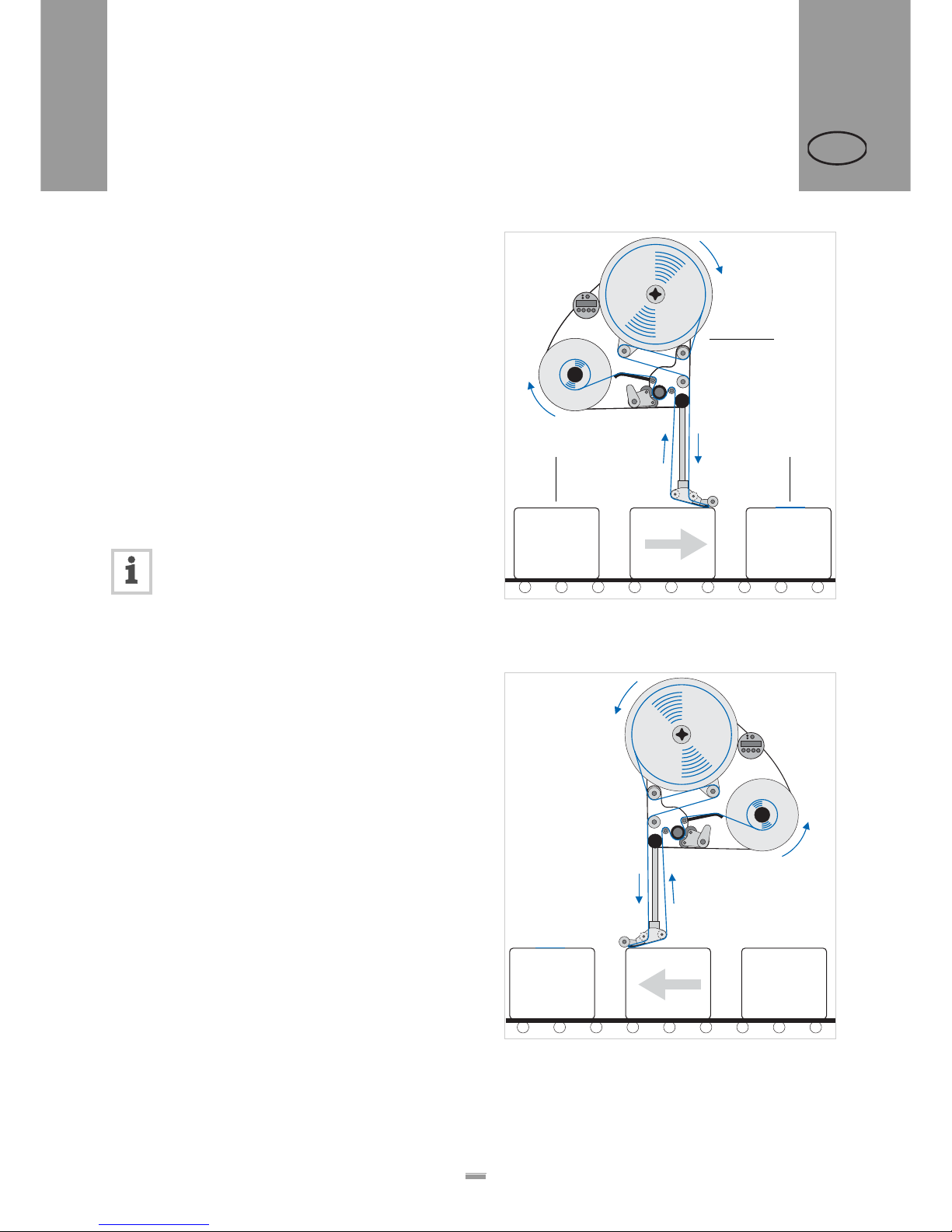
The ALS 104 Label Dispenser is available in two designs for differing conveyor belt directions.
Right-handed version
– The products are transported from left to right [10].
– The dispensing edge is located on the right side.
– Abbreviation: RH
Left-handed version
– The products are transported from right to left [11].
– The dispensing edge is located on the left side.
– Abbreviation: LH
The label dispenser operation described in this
manual is based on the right-handed version.
The left-handed version is only taken into account if the explanations or figures of the designs differ significantly.
[10] Right-handed version
A ALS104
B Product on the conveyor belt
C Labelled product
[11] Left-handed version
A
B C
Page 20
20
2PRODUCT DESCRIPTION
2.2 OPTIONS
ALS
104
GB
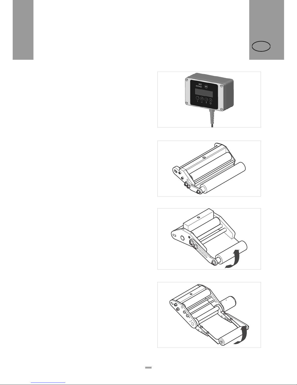
External control panel
– An external control panel can be connected in
addition to the integrated control panel.
– An external control panel is useful if the standard
control panel is inaccessible due to the position in
which the unit is installed.
Fixed dispensing edge
– The dispensing edge has a fixed connection to the
brackets.
– To adjust the vertical position, lift/lower the entire
device.
– The slope angle can be adjusted by rotating the
brackets (see the service manual for further details).
Swivelling dispensing edge
– The position of the dispensing edge can be adjusted
vertically.
– The device need not be moved to adjust the position
of the dispensing edge; the device’s mounting need
not be dismantled.
Spring-loaded dispensing edge
– The dispensing edge is pivoted. A torsion spring in
the dispensing head presses the dispensing edge
downwards and onto the surface of the product.
– Allows compensation for height differences
between the products or on the product surface.
[12] External control panel
[13] Standard dispensing edge
[14] Swivelling dispensing edge
[15] Spring-loaded dispensing edge
2.2 OPTIONS
Page 21
21
2PRODUCT DESCRIPTION
2.2 OPTIONS
ALS
104
GB
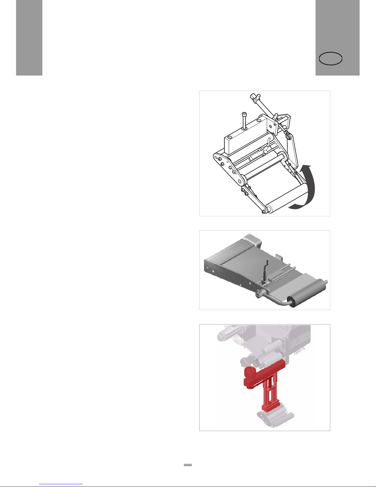
Pneumatic dispensing edge
– The dispensing edge is pivoted in the dispensing
head. Compressed air presses the dispensing edge
onto the surface of the product.
– Allows compensation for height differences
between the products or on the product surface.
V-shape dispensing edge
– An alternative for applications which do not leave
enough space for the standard dispensing edge holder, which juts out to the bottom side.
– Is attached directly to the machine
Adjustable dispensing edge holder
Enables a vertical fine adjustment of the dispensing
edge towards the product without moving the machine.
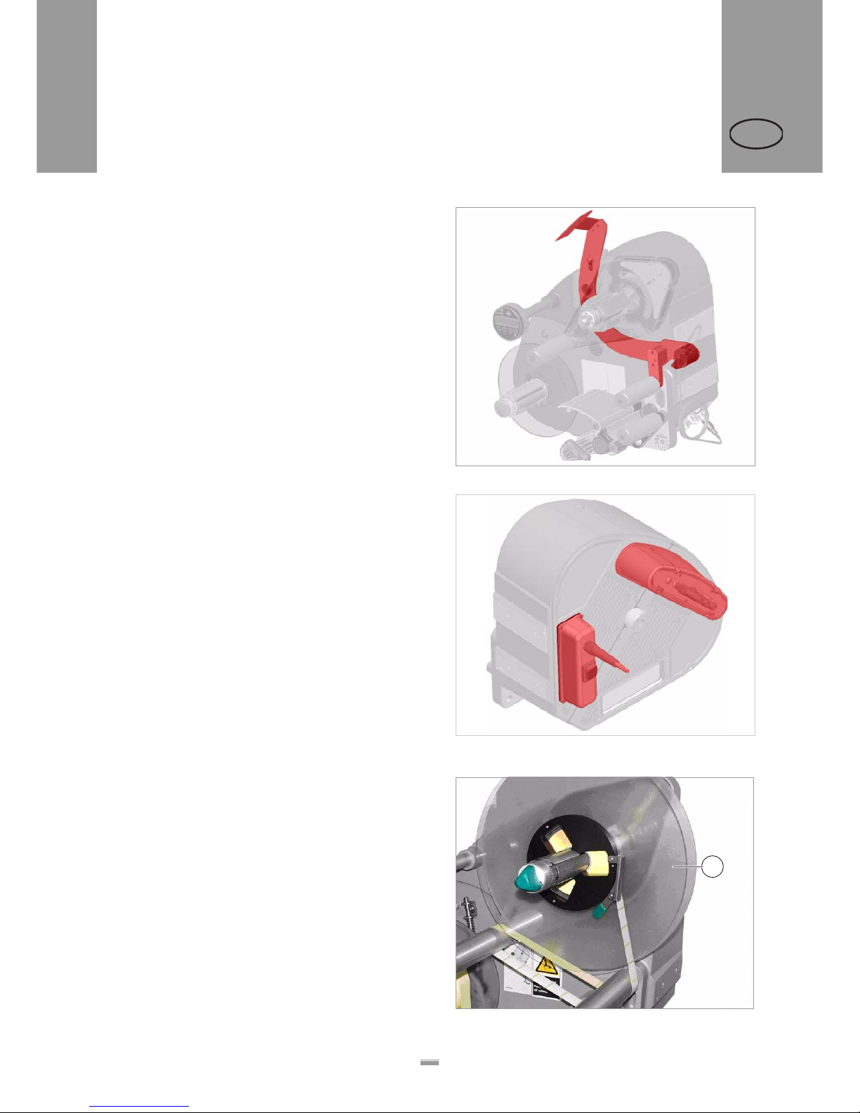
[16] Pneumatic dispensing edge
[17] V-shape dispensing edge
[18] Adjustable dispensing edge holder (pictured red resp. dark
gray)
Page 22
22
2PRODUCT DESCRIPTION
2.2 OPTIONS
ALS
104
GB
Outer Diameter control sensor
The outer diameter control sensor (OD sensor) triggers
a warning, if the label roll outer diameter falls below a
certain, adjustable value.
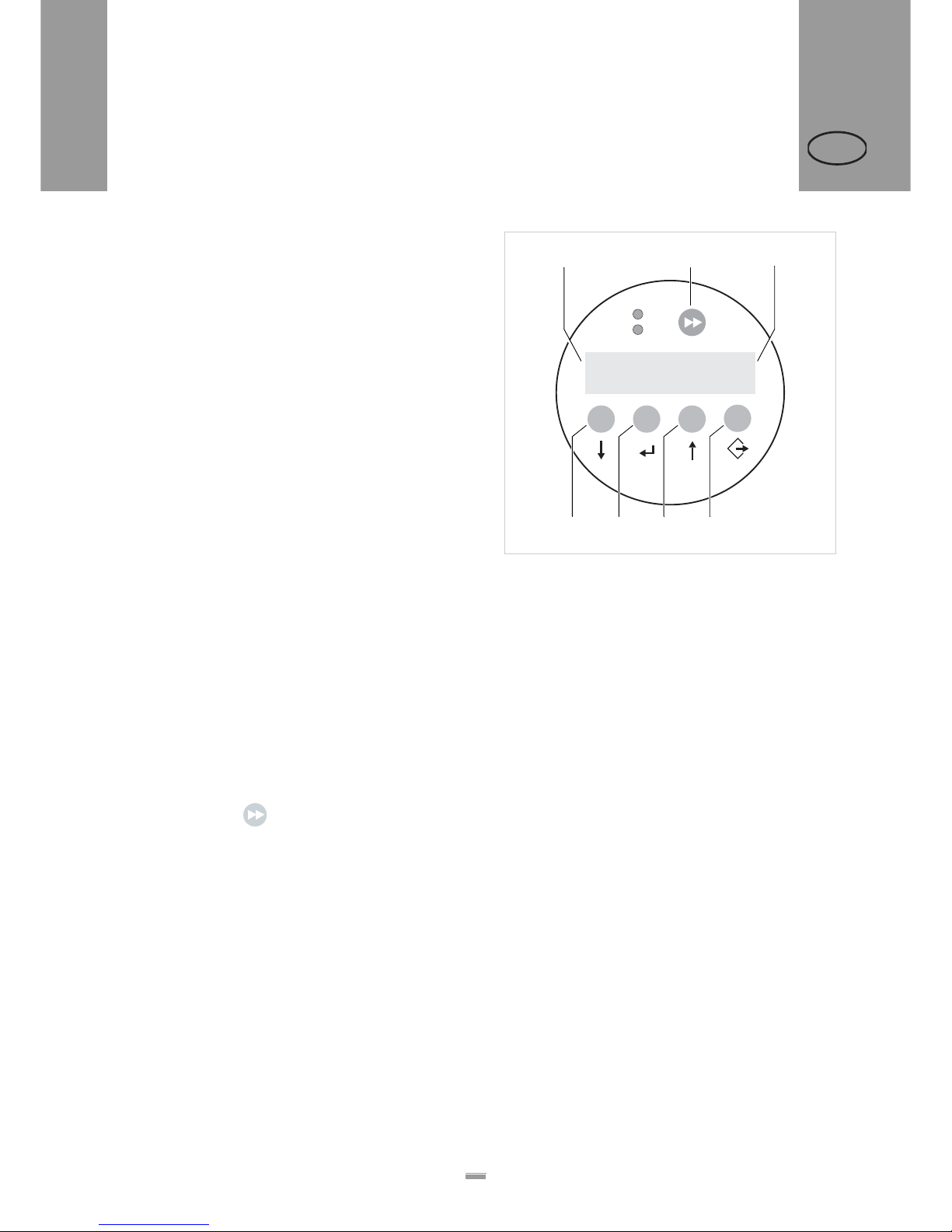
Dust/Splash guard
Available only for ALS20X.
Additional sealing of the electrical connections an d of
the housing fulfils the requirements of the IP65 protection class [19].
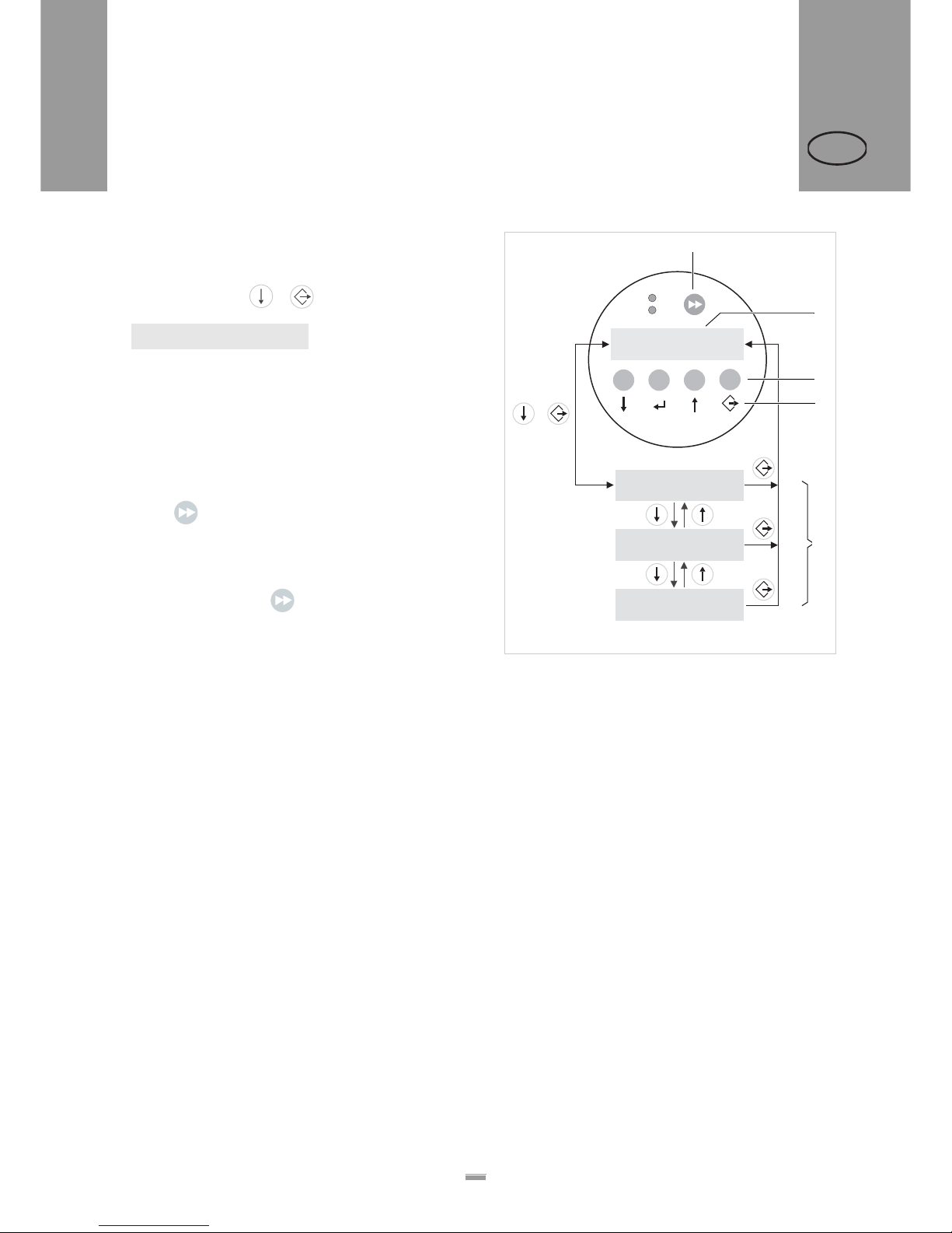
Additional material guide disk
The additional material guide disk [21A] improves the
lateral guiding of the material roll. This option is especially recommended, if very narrow material (< 30mm
width) is processed.
[19] OD sensor (pictured red resp. dark gray)
[20] Dust/splash guard of the electrical connections (pictured red
resp. dark gray)
[21] Additional material guide disk (A)
A
Page 23

23
2PRODUCT DESCRIPTION
2.2 OPTIONS
ALS
104
GB
Printer
– If necessary, you can mount a hot stamp printer (not
available from Avery Dennison) onto the holder
brackets of the dispensing edge.
– Example of use: Printing consecutive numbers onto
labels.
Narrow label spring kit
Narrow label material may under certain circumstances
tear off or expand in a way which results in poor
labelling precision. In those cases, it is adviseable to
install weaker dancer arm springs.
Page 24
24
2PRODUCT DESCRIPTION
2.3 OPERATING MODES
ALS
104
GB
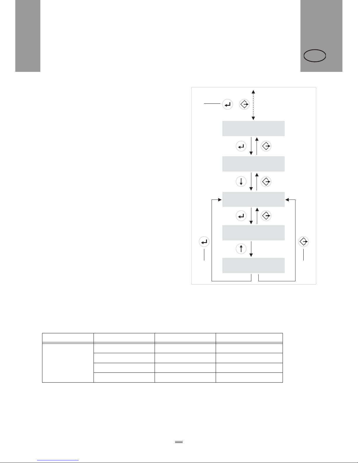
2.3.1 Dispensing mode
– This is the operating mode of the unit when switched
on.
– The display shows the dispensing speed [22A] and
the start offset [22C].
– In dispensing mode, the button assignments are as
shown on the buttons.
– Both settings can be increased (‘+’ button) or
lowered
(‘–’-button) during dispensing operation [22].
– For more information on adjusting the dispensing
operation, see “Function menu settings” on page 38
Dispensing speed
– Setting range:
fix: [5.0…30.0] m/min
var: [0.0…30.0] m/min
– Display fix: The dispensing speed is constant.
– Display var: The dispensing speed adjusts to the
speed of the conveyor belt (‘speed adaption’).
Start offset
– Setting range: [0.0…999.9] mm
– The start offset indicates the distance between the
product sensor and the dispensing edge.
Dispensing manually
To manually trigger the dispensing of individual labels:
£ Press the button .
– Dispensing speed: As specified in the setting (see
above).
[22] Control panel and button functions in dispensing mode.
A Dispensing speed display (here: 12.2 m/min)
B Dispense label button
C Start offset display (here: 0 mm)
D Button to lower dispensing speed
E Button to increase dispensing speed
F Button to lower start offset
G Button to increase start offset
Speed
12.2 fix
Offset
0.0
+
+
–
–
ON
STATUS
A C
D E F G
B
2.3 OPERATING MODES
Page 25
25
2PRODUCT DESCRIPTION
2.3 OPERATING MODES
ALS
104
GB
2.3.2 Configuration mode
Switching to configuration mode:
£ Press the buttons + .
– Display:
– LABEL SETUP is the name of the first menu shown
directly after switching to configuration mode.
– In configuration mode, the button assignments are
as shown below the buttons [23D].
Function of the double-arrow button
To dispense individual labels:
£ Press button briefly (less than two seconds).
– Dispensing speed: As specified in the configuration;
‘Speed Adaption’ is not active.
To automatically calibrate the label length:
£ Hold down the button for a while (more than two
seconds).
– Is equivalent to the function LABEL SETUP > Label Size.
Menus
In ‘Configuration’ mode, the user has access to several
menus providing a fixed sequence of various functions
that can be carried out.
In addition to the LABEL SETUP menu, there are also
the menus MACHINE SETUP and SERVICE
FUNCTION.
Figure [23] shows the button functions for switching
between individual menus and for leaving the
configuration mode.
LABEL SETUP
[23] Control panel and button functions in configuration mode.
A Button for triggering a dispensing procedure and for
starting the measurement of lengths.
B Display in dispensing mode
C Explanation of buttons in dispensing mode
D Explanation of buttons in configuration mode
E Display indicators in configuration mode
LABEL SETUP
MACHINE SETUP
SERVICE FUNCTION
Speed
12.2 fix
Offset
0.0
+
+
–
–
ON
STATUS
+
B
E
C
D
A
Page 26
26
2PRODUCT DESCRIPTION
2.3 OPERATING MODES
ALS
104
GB
Functions
Every submenu contains functions for setting the unit
controls.
Figure [24] shows the buttons functions for changing
the configuration with the example of LABEL SETUP >
Missing Labels.
2.3.3 Function overview
[24] Button functions when using the LABEL SETUP > Missing
Labels function.
A Button combination for ‘Switching between configuration
and dispensing mode’
B Button to ‘Accept changes’
C Button to ‘Cancel changes’
LABEL SETUP
3x
LABEL SETUP
Missing Labels
Missing Labels
Alarm after 1
Dispense speed
Alarm after 2
+
LABEL SETUP
Label Size
A
B C
1) The functions in the SERVICE FUNCTIONS menu are password protected.
[25] Overview of the menus and functions.
Menus: LABEL SETUP MACHINE SETUP SERVICE FUNCTION
1)
Functions: Label Size Factory Settings Run continuously
Stop Sensor Pos. Speed Adaption Machine Type
Product Length Encoder Resol.
Missing Labels Encoder Diameter
Page 27
27
2PRODUCT DESCRIPTION
2.3 OPERATING MODES
ALS
104
GB
2.3.4 Function descriptions
LABEL SETUP menu
Function Label Size
– Automatically calibrates the label length
– Display:
– Press in order to start the calibration; four labels
are dispensed during the calibration.
– Display after the calibration:
– Press to accept the measured value,
to quit the function and retain the former value.
Function Stop Sensor Pos.:
– Stop sensor position
– Distance between the label sensor (stop sensor)
and the dispensing edge
– This setting determines how far out the labels
protrude over the dispensing edge when the unit is
in its waiting position.
– Setting range: [0.0…999.9] mm
Function Product Length:
– Product length
– Prevents the product sensor from being incorrectly
activated. Once a product has triggered the sensor,
the sensor is locked until the product has passed
under the sensor.
– Setting range: [0.0…999.9] mm
Function Missing Labels:
– Missing labels
– In practice, sometimes labels are missing from the
backing paper. The fault tolerance is defined using
the Missing Labels function.
– Set the number of missing labels that must be
detected before an error message is triggered.
– Setting range: [1…10]
MACHINE SETUP menu
Function Factory Settings
– Restores factory settings
Function Speed Adaption
– Settings: On/Off
– On: The dispensing speed is automatically adjusted
to the speed of the conveyor belt; this setting only
functions if a rotary encoder is connected.
– Off: The dispensing speed is constant and is as set
in dispensing mode (see section “Dispensing mode”
on page 24.)
Function Encoder Resol.
– Determines the resolution of the rotary encoder.
– Setting range: [10…9999] pulse/revolutions
Function Encoder Diameter
– Determines the diameter of the measuring wheel
installed with the rotary encoder.
– Setting range: [3.2…318.3] mm
– Display:
– The right side (yy.y) shows the speed of the
conveyor belt currently measured. By changing the
measuring wheel diameter, this value can be
adjusted to the actual conveyor speed.
SERVICE FUNCTION menu
Function Run continuously
– A test function that turns on the motor
– To stop motor: Any button
Function Machine Type
– ALS104 LH: Left-handed unit
– ALS104 RH: Right-handed unit
Current Size:
107.7 mm Detect?
Size found:
107.7 mm Accept?
Encoder Diameter
x.x yy.y var
Page 28
28
3BEFORE OPERATION
2.4 INSERTING LABEL MATERIAL
ALS
104
GB
2.4.1 Prerequisites
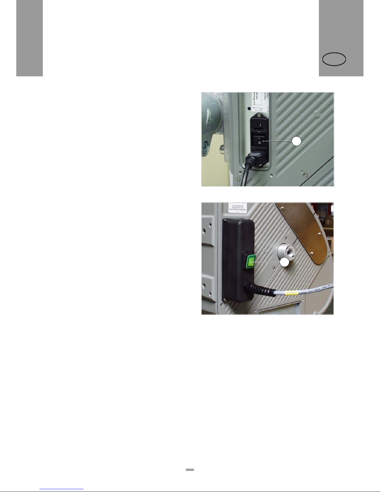
The label dispenser is turned off at the main switch
– Standard machine: switch set to “O” [26A]
– Machine with dust/splash guard: switch does not
light [27A]
£ Check that the safety installations are working
properly.
£ Inspect the machinery for any visible damage.
Report any ascertained defects immediately.
£ Remove any unnecessary materials and objects
from the operating area of the unit.
£ Ensure that only authorised persons are within the
operating range of the machine.
£ Use the required personal protective equipment
correctly; forexample, wear a hairnet, safety
glasses.
[26] Main switch (A) on the housing.
[27] Main switch on ALS 104 with dust/splash guard option.
A
A
2.4 INSERTING LABEL MATERIAL
Page 29
29
3BEFORE OPERATION
2.4 INSERTING LABEL MATERIAL
ALS
104
GB
2.4.2 Inserting a label roll
WARNING!
Risk of injury due to moving and rapidly
rotating parts!
£ Before inserting the label roll, ensure that
the device is turned off at the main
switch.
£ Do not under any circumstances turn the
device on before the label strip is
threaded in completely.
Removing spent backing paper
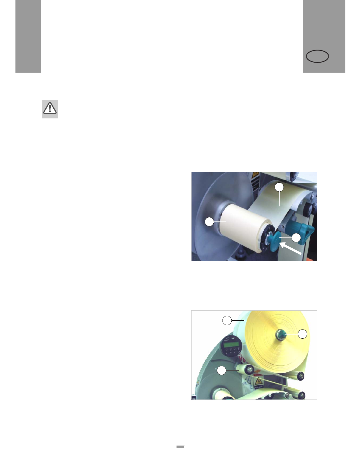
Assuming backing paper has gathered on the rewinder
[28A] :
£ Press the release button [28C].
– The tensioning mechanism of the rewinder is
slackened.
£ Remove the rewound backing paper.
Removing glue residue
£ If necessary, clean the following components:
– Dispensing plate
– Deflection rollers
– Drive rollers
– Pressure roller
£ Follow the directions provided in section
“Maintenance and cleaning” on page 42.
Inserting a new label roll
£ Push the material roll [29A] onto the unwinder as far
as it will go.
£ Rotate the rotary knob [29B] in a clockwise direction
until the label roll sits tightly.
£ Run the label strip around the dancer arm as shown
in the figure [29C].
– The material strip must run in a slightly different
route when using label rolls with a ‘labels facing
inwards’ winding direction. Insert the roll in such a
way that it unwinds in an anticlockwise direction
(see “Threading guide” on page 30).
[28] A Rewound backing paper
B Backing paper path
C Release button
B
C
A
[29] Fasten the label roll to the dispenser (the winding direction
of the roll should be with the labels facing outwards).
A
C
B
Page 30
30
3BEFORE OPERATION
2.4 INSERTING LABEL MATERIAL
ALS
104
GB
2.4.3 Threading the label web
Threading guide
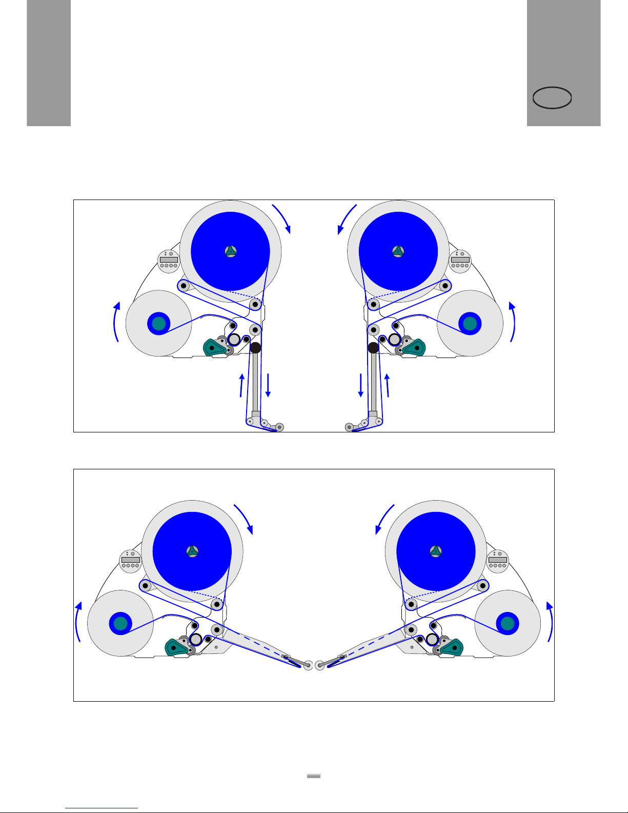
[30] Threading guide for ALS104 with L-shape dispensing edge *.
A Right-handed version B Left-handed version
[31] Threading guide for ALS104 with V-shape dispensing edge
*
.
A Right-handed version B Left-handed version
*) Solid line: Path for label rolls with labels facing outwards. Dottet line: differing path for label rolls with labels facing inwards.
BA
BA
Page 31
31
3BEFORE OPERATION
2.4 INSERTING LABEL MATERIAL
ALS
104
GB
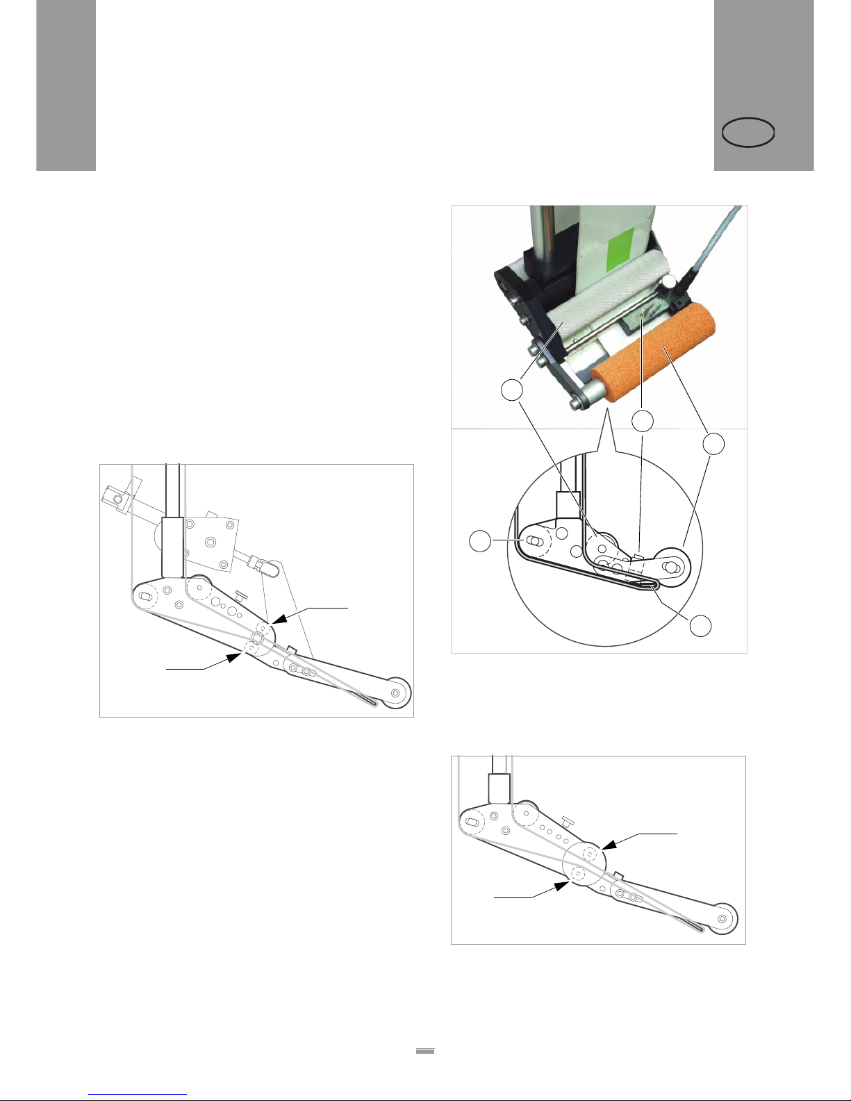
Threading the label roll at the dispensing
edge
£ Unroll around 1m of label strip and remove the
labels from it.
£ Pass the backing paper around the first deflection
roller [32A] and through the slot in the sensor [32B].
£ Feed the backing paper under the pressure roller
[32C] to the dispensing plate [32D].
£ Feed the backing paper around the dispensing plate
to the second deflection roller [32E].
Spring loaded [33] and pneumatic [34] L-Shape di spensing edges:
£ Additionally pass the backing paper between the
two slim deflection rollers at the joint [33A] [34A].
[34] Path of the label strip at the pneumatic dispensing edge (option).
[32] Path of the label strip near the edge of the dispenser.
A 1st deflection roller
B Label sensor
C Pressure roller
D Dispensing plate
E 2nd deflection roller
[33] Path of the label strip at the spring loaded dispensing edge
(option).
C
A
B
D
E
A
A
A
A
Page 32
32
3BEFORE OPERATION
2.4 INSERTING LABEL MATERIAL
ALS
104
GB
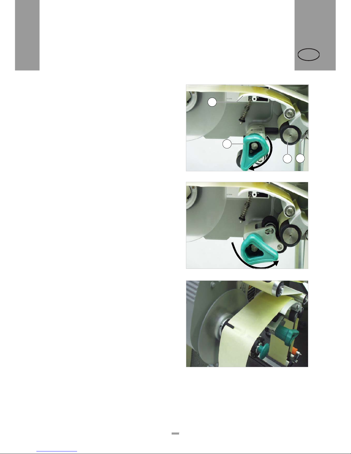
Threading the label roll onto the drive
roller
£ Open the pressure roller. To do so, rotate the lever
[35D] in a clockwise direction.
£ Feed the backing paper around the deflection roller
[35B], drive roller [35C] and the tensioning plate
[35A].
£ Close the pressure roller. To do so, rotate the lever
anticlockwise until it snaps in noticeably.
Fastening the label roll to the rewinder
£ Clamp the backing paper to the rewinder a s shown
and tighten it [37].
[35] Opening the pressure roller.
[36] Closing the pressure roller.
C
B
A
D
[37] Fastening the backing paper to the rewinder.
Page 33
33
3BEFORE OPERATION
3.1 ELECTRICAL CONNECTIONS
ALS
104
GB
3.1.1 Power supply standard
machine
WARNING!
This machine operates using mains voltage!
Touching live electrical parts may exp ose
you to hazardous electrical currents and
may lead to burns.
£ Make sure that the unit is switched off
before connecting the power cable.
£ Only operate the unit with mains voltage
set in the fuse insert.
£ Ensure that the unit is set to receive the
mains voltage supplied by your electricity
provider.
£ Only connect the unit to a grounded
power socket fitted to authorised
standards.
£ The power cable should not be more than
3 m long.
The device is only completely disconnected
from the mains if the power cableis
unplugged. Therefore:
£ Make sure the power supply socket is
accessible.
£ In case of emergency, switch off the
device and disconnect the power cable!
Checking the power supply setting
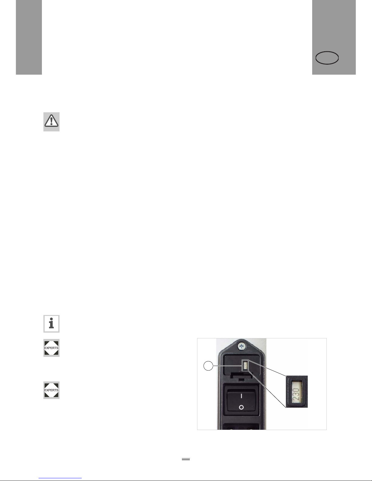
The ALS104 is suitable for operation with a
power supply of 230V (AC) or 115V (AC).
If you are unsure of what mains voltage your local electricity supplier provides, refer to a qualified service technician.
£ Check whether the right voltage is set in the
display of the fuse insert [38A].
Only a qualified service technician is allowed to
change the power supply setting.
You can find further information for performing
this operation in the service manual.
[38] Voltage display on the fuse insert (showing 230 V here).
A
3 BEFORE OPERATION
3.1 ELECTRICAL CONNECTIONS
Page 34
34
3BEFORE OPERATION
3.1 ELECTRICAL CONNECTIONS
ALS
104
GB
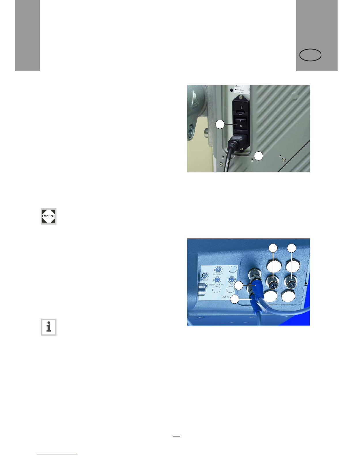
Connecting the power cable.
£ Ensure that power switch [39A] is set to “O” (off).
£ Using the supplied power cable, plug the ALS104
into a socket connected to the mains supply.
3.1.2 Power supply with dust/splash
guard option
ALS104 labeller with dust/splash guard option
(IP65) may only be connected by qualified service technicians.
3.1.3 Connecting sensors
£ Check whether the required sensors are connecte d
[40] before turning on the ALS104.
The minimum required sensors:
– Label sensor (installation location: dispensing edge)
– Product sensor (installation location: conveyor belt)
You have the option of fitting additional sensors as well:
– Speed sensor (required for speed adaption)
– Outer diameter checking sensor (provides advance
warning of the end of a label roll)
You can find further information regarding suitable sensor types, pin assignments, and the
like in the service manual.
[39] Power cable (B) plugged in.
B
A
[40] Sensor connectors:
A Product sensor
B Label sensor
C Optional: Speed sensor
D Optional: Roll diameter (RD) sensor
B
A
C D
Page 35
35
3BEFORE OPERATION
3.2 MECHANICAL SETTINGS
ALS
104
GB
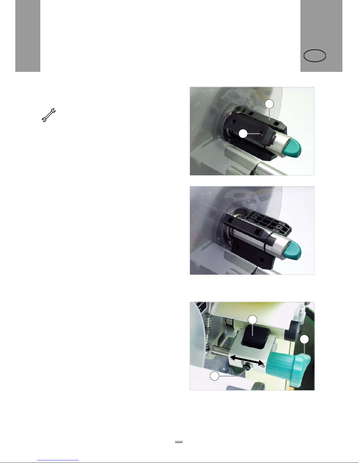
3.2.1 Adjusting the unwinder’s core
diameter
Tool:
– 3 mm hexagon (Allen) screwdriver
The unwinder can be adjusted with core adapters [41B]
to fit the inner diameter of the label roll. The adapters
must be fitted and dismantled in different ways
depending on this diameter:
– 38.1mm (1”) core
£ Unscrew the screws [41A] (3 for each adapter) and
remove the adapters.
– 76.2mm (3”) core
£ Screw on the adapters, as is shown in Figure [41].
– 101.6 mm (4”) core
£ Screw on the adapters, as is shown in Figure [42].
3.2.2 Positioning the pressure roller
£ Open the pressure roller [43B]. To do so, rotate the
lever [43C] in a clockwise direction until the roller
snaps up.
£ Release thumb screw [43A].
£ Align the pressure roller over the backing paper so
that it is centred.
£ Close the pressure roller.
£ Screw the thumb screw tight.
[41] Core adapter position for a core diameter of 76.2 mm.
[42] Core adapter position for a core diameter of 101.6 mm.
A
B
[43] Setting the position of the pressure roller (B).
A
B
C
3.2 MECHANICAL SETTINGS
Page 36
36
3BEFORE OPERATION
3.2 MECHANICAL SETTINGS
ALS
104
GB
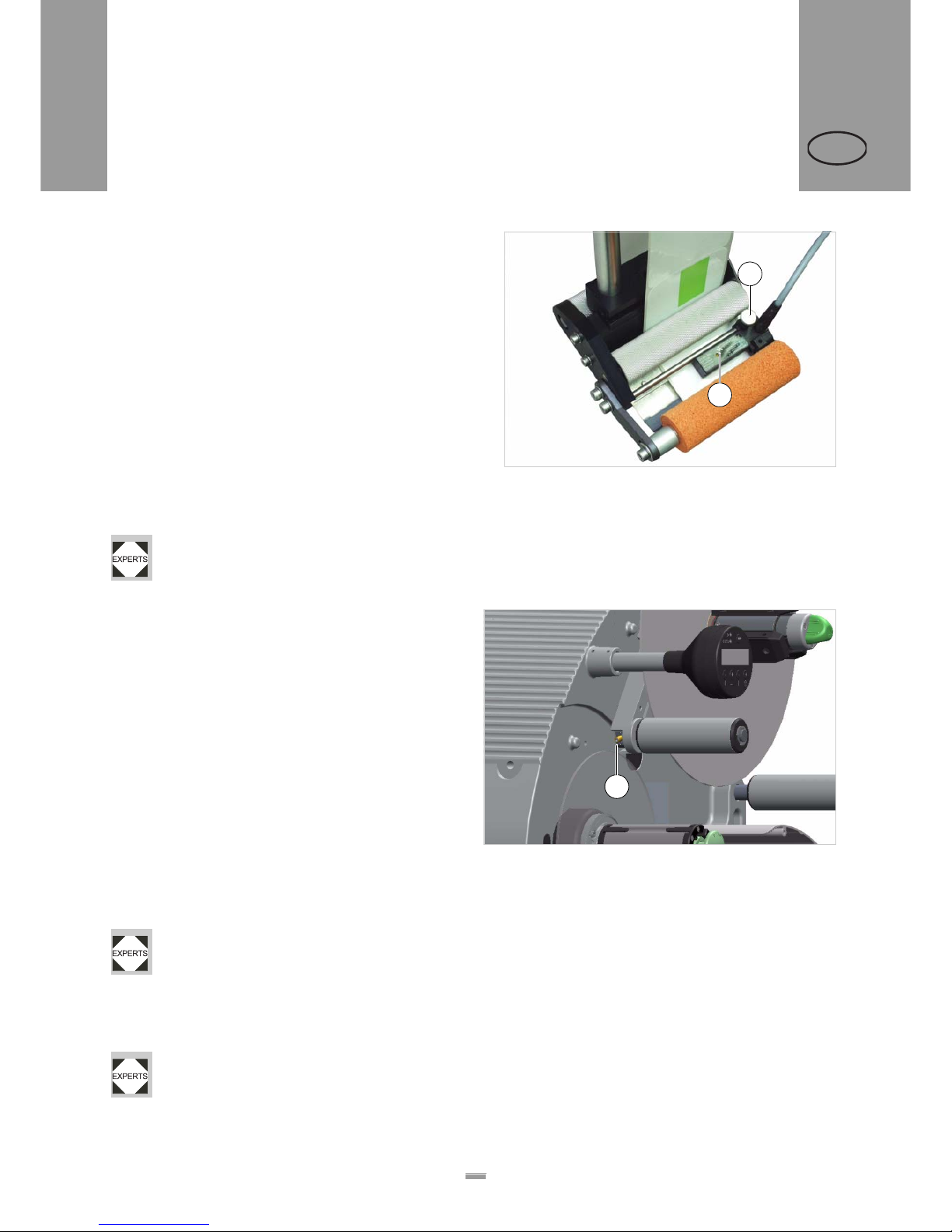
3.2.3 Calibrating the label sensor
Positioning the sensor:
£ Release the thumb screw.
£ Position the sensor along the axle in such a way as
to allow it to register the spaces between the labels.
Configuring the sensor:
– The settings required for the sensor depend on the
employed materials. The standard settings are
suitable for many types of label materials.
£ Check whether the LED is lit [44A] when the sensor
is above a space between labels.
– If this is not the case, the sensor must be
configured.
£ You should refer to a qualified technician to help
configure the sensor.
– Configuration instructions: See the service
manual.
3.2.4 Setting the dancer arm
restoring force
The unwinder dancer arm is preset in a way, that a wide
range of label materials can be processed whithout having to change the dancer arms restoring force.
Even so, very narrow label material can under certain
circumstances tear off or expand in a way which results
in poor labelling precision. In those cases, the restoring
force must be decreased.
Tool:
2.5mm hex socket screwdriver
£ Turn the adjusting screw [45A] on the dancer arm
left to increase restoring force.
£ Turn the adjusting screw [45A] on the dancer arm
right to decrease restoring force.
A service technician can restore the factory setting, see service manual chap. 6.2.3 section
„Adjusting restoring force of dancer arm“.
If the problem still occurs, although the restoring force
is already set to a minimum, there is the option of building in some weaker springs.
The springs must be built in by a qualified service technician. Instructions can be found in the
service manual, chap. 6.2.3 section „Narrow label kit“.
[44] Label sensor from Wenglor, model OPT242-P800
B
A
[45] Setting screw (A) at the unwinder dancer arm.
A
Page 37
37
4OPERATION
4.1 START-UP AND SHUTDOWN
ALS
104
GB
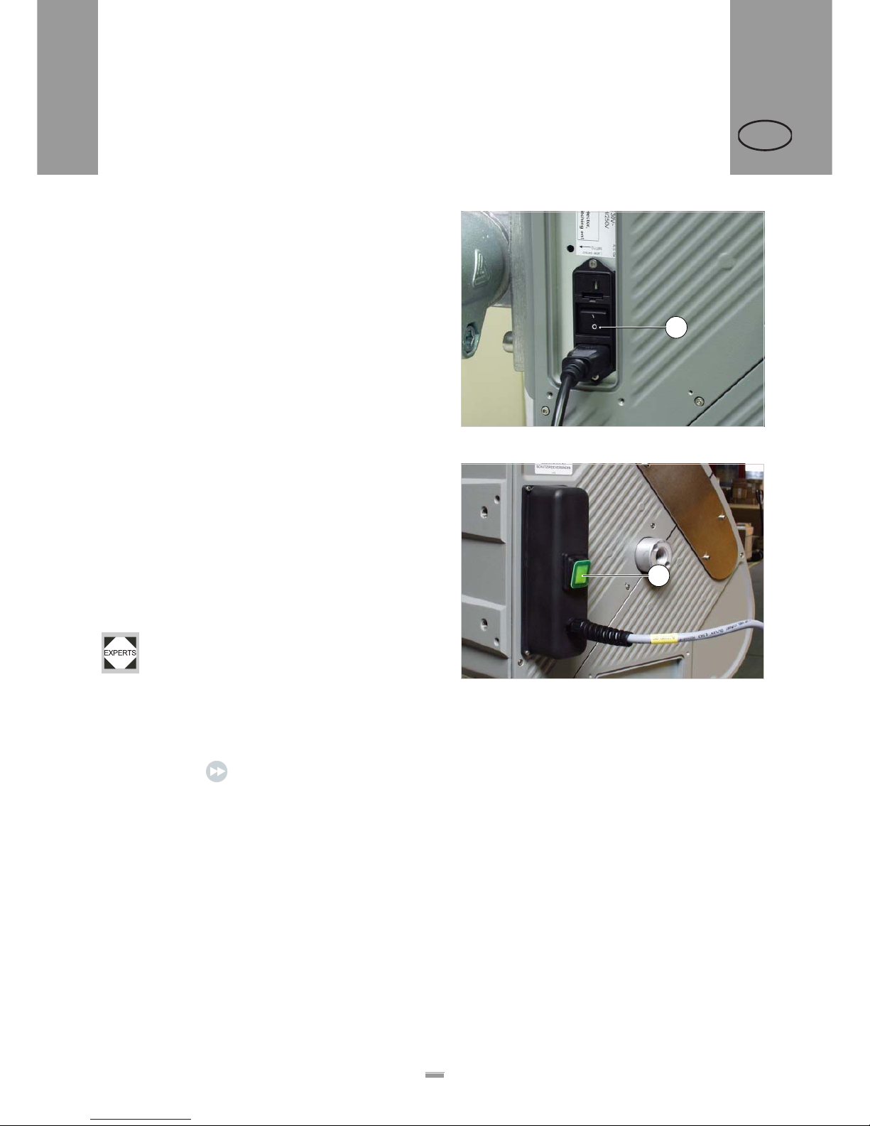
4.1.1 Turning on the unit
£ Set the main switch [46A] of the unit to ‘I’ (On).
Machine with dust/splash guard option:
– The main switch [47A] lights, if the machine is swit-
ched on.
£ Operate the main switch.
– Once on, the ALS104 is in dispensing mode; in
other words, triggering the product sensor will cause
a label to be dispensed.
– More information on the dispensing mode can be
found in the section “Dispensing mode” on page 24.
4.1.2 Starting label dispensing
Dispensing with a product sensor
Once switched on, the ALS104 is in dispensing mode;
this means that triggering the product sensor will cause
a label to be dispensed.
Prerequisites:
– The label length must be specified
– The product sensor must be connected
– The sensor type (PNP/NPN) must be
properly set.
Dispensing without a product sensor
It is also possible to trigger the dispensing process
without a product sensor:
£ Press the key briefly.
4.1.3 Stopping the dispensing
process
£ Set the main switch [46A] of the unit to ‘O’ (Off).
[46] Main switch (A) of ALS 104.
[47] Mains switch (A) of ALS 104 with dust/splash guard option.
A
A
4 OPERATION
4.1 START-UP AND SHUTDOWN
Page 38
38
4OPERATION
4.2 CONFIGURATION AND MONITORING
ALS
104
GB
4.2.1 Function menu settings
Label length
The label length is calibrated automatically.
Prerequisites:
– Label material is inserted
£ Call up the function LABEL SETUP > Label Size:
£ Press the key to start the calibration. ALS104
then dispenses four labels in order to determine
their length:
£ Press the key to accept the calibrated value, or
press to retain the old value.
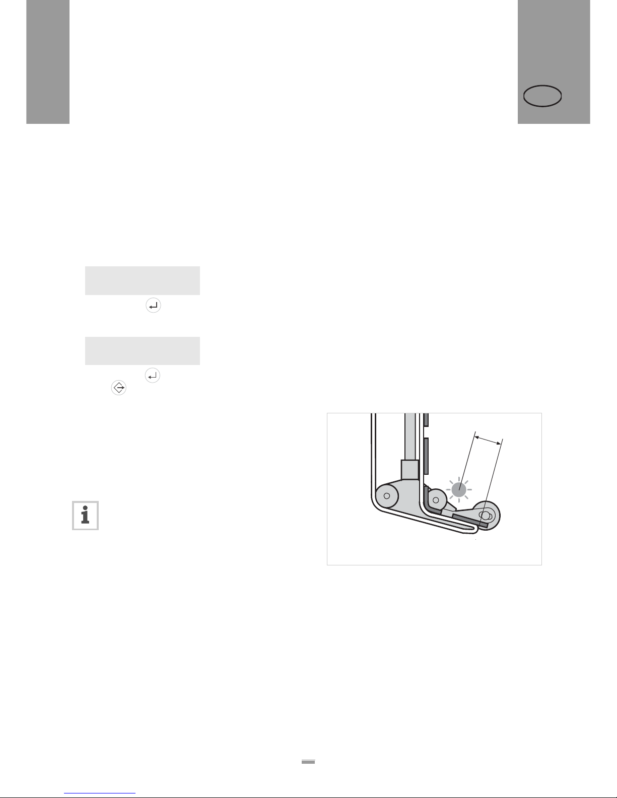
Label stop position
Prerequisites:
– The label length must be specified
The next label to be dispensed is halted in the label
stop position. This is useful if the label protrudes ov er
the dispensing edge somewhat [48].
ALS104 is pre-configured for use with the
supplied label sensor. If this sensor is
employed, the label stop position setting will
only require minimal correction.
Correcting the default setting:
£ Call up LABEL SETUP > Stop sensor pos..
£ Increase the value to increase the overhang or
lower the value to reduce the overhang.
The value ‘0’ will cause the label to stop directly with its
front edge under the label sensor.
The front edge of the label to be dispensed should be
flush with the dispensing edge:
£ Enter the distance [48A] between the label sensor
and the dispensing edge.
The front edge of the label to be dispensed should
overhang:
£ Add the length of the overhang to the distance
between the label sensor and the dispensing edge.
Current Size:
0.0 mm Detect?
Size Found:
107.7 mm Accept?
[48] Label stop position (A)
A
4.2 CONFIGURATION AND MONITORING
Page 39
39
4OPERATION
4.2 CONFIGURATION AND MONITORING
ALS
104
GB
Dispensing speed
The dispensing speed can be set to a fixed value or can
be configured to automatically adjust to the speed of
the conveyor belt (speed adaption). The second
possibility requires a speed sensor to be connected; it
measures and relays the conveyor speed to the
dispenser.
Configuring a fixed value:
£ Set the speed in dispensing mode with the two left
keys (see “Dispensing mode” on page 24).
Configuring speed adaption:
£ Turn the function on by setting MACHINE SETUP >
Speed Adaption to ‘On’.
£MACHINE SETUP > Encoder Resol. and
MACHINE SETUP > Encoder Diameter set as
appropriate for the employed speed sensor.
– See the service manual for information on
suitable speed sensors.
Page 40
40
4OPERATION
4.2 CONFIGURATION AND MONITORING
ALS
104
GB
Label position on the product
Prerequisites:
– The label length must be specified.
– The label stop position must be set.
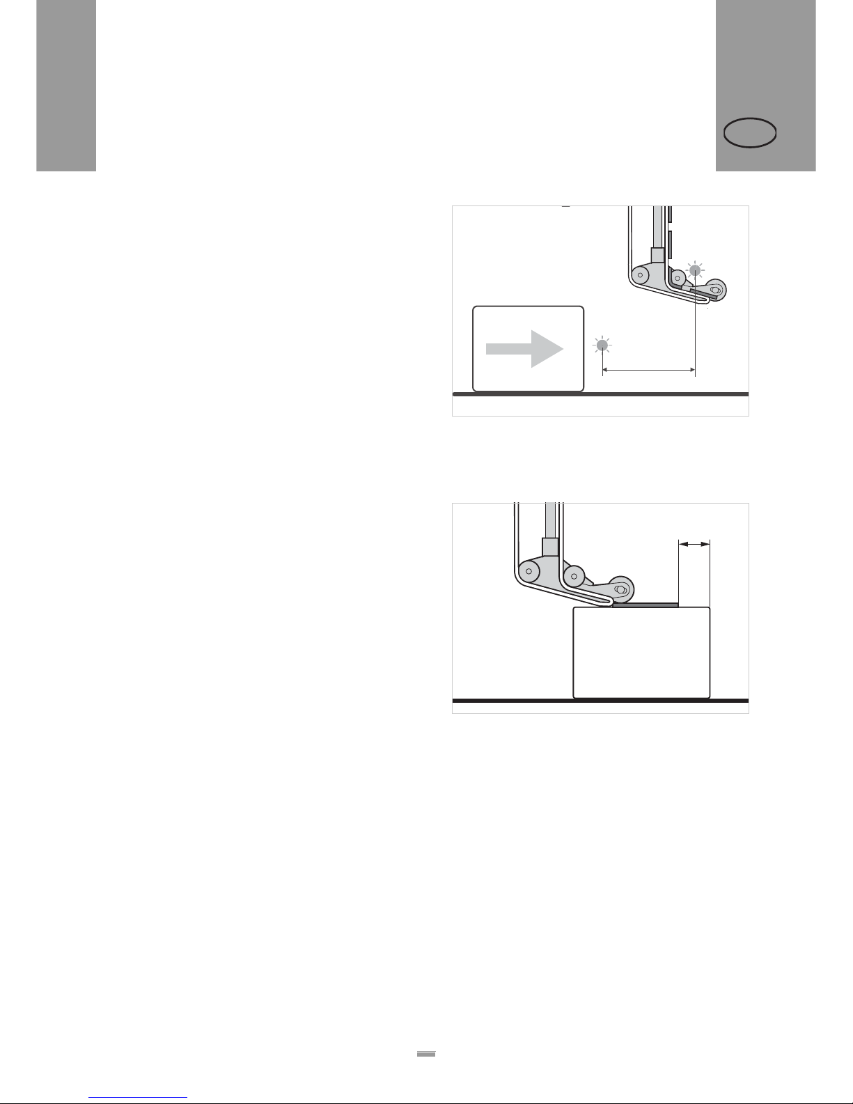
The Start Offset is se t in dispensing mode with the right
two keys (see “Dispensing mode” on page 24).
– The label should be flush with the front edge of the
product:
£ Enter the distance between the product sensor and
the label sensor [49A].
– The label should stop at a distance from the front
edge of the product:
£ Increase the start offset [50A] to increase the
distance to the product’s front edge.
[49] Distance between the product sensor (left) and the label
sensor (right).
A
[50] Distance (A) between the label and the product’s front
A
Page 41

41
4OPERATION
4.2 CONFIGURATION AND MONITORING
ALS
104
GB
4.2.2 Monitoring functions
While in dispensing mode, an electronic control
monitors the following functions:
Missing labels
A label missing from the label roll does not normally
affect the dispensing operation, because the label feed
continues until a label’s edge passes under the label
sensor.
Nonetheless, it can be important that missing labels are
reported. By configuring the function LABEL SETUP
>Missing Labels, you can specify whether an error
message is triggered after one or several missing
labels.
Recognising the end of the label roll in
advance
If the end of the label roll is to be recognised prior to the
last label being dispensed, it is recommended that a
sensor is used to check the outer diameter of the roll.
This sensor, which is available as an extra, is mounted
on the unit in such a way as to trigger an error message
as soon as the roll’s diameter falls short of a specified
value. This diameter can be configured.
Page 42
42
5AFTER OPERATION
5.1 MAINTENANCE AND CLEANING
ALS
104
GB
5.1.1 Changing fuses
WARNING!
The machine operates using mains voltage!
Touching live electrical parts may exp ose
you to hazardous electrical currents and
may lead to burns.
£ Make sure that the machine is switched
off and the power cable is unplugged
before removing the fuse insert.
CAUTION!
Risk of fire, if a wrong fuse type is inserted.
£ Only replace fuses with the type and
rating specified in this manual.
ALS104 with dust/splash guard: Fuses may
only be replaced by qualified service technicians.
£ Turn off the unit. Unplug the power cable.
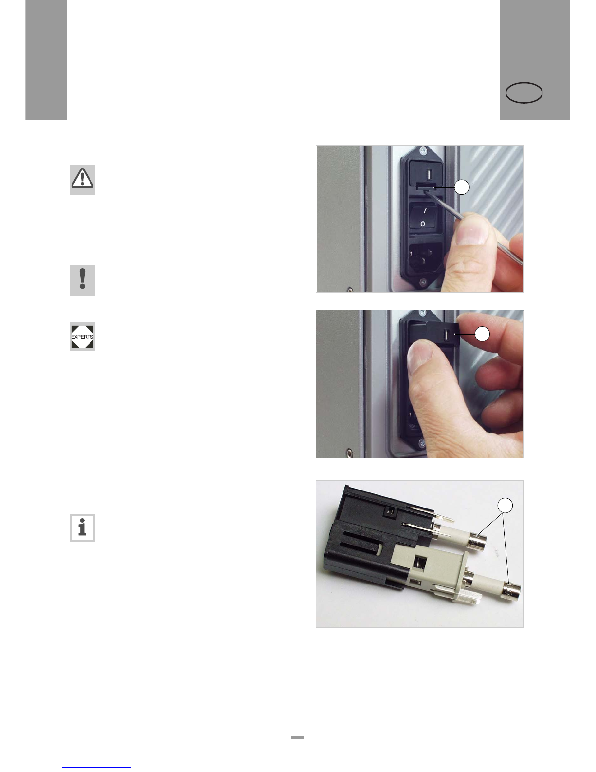
£ Remove the fuse insert. To do this, press the latch
upwards [51A] and pull out the insert [52A].
– The fuse insert is located directly above the On/Off
switch.
£ Take the fuses out of the fuse insert.
£ Replace defective fuses.
Required fuse type:
– 2x F5AH / 250V
– The same fuse type is required for 230V as
for 115V.
– The fuses must conform to IEC 60127-2/5
(for example, “Wickmann 181 Series”)
[51] Unlock the fuse insert.
[52] Remove the fuse insert (A).
A
A
[53] Remove (A) fuses.
A
5 AFTER OPERATION
5.1 MAINTENANCE AND CLEANING
Page 43
43
5AFTER OPERATION
5.1 MAINTENANCE AND CLEANING
ALS
104
GB
5.1.2 Cleaning agents
Cleaning agents for rubber rollers:
– Roller cleaner, order number 98925.
If other cleaning agents are used, there is a
chance the rubber may corrode.
Cleaning agents for metal deflection rollers:
– Cleaning solvent, alcohol-based solvent,
isopropyl alcohol, spray for removing labels
Cleaning the unit’s housing:
– Commercially available neutral cleaning
liquid
WARNING!
Cleaning solvent, alcohol-based solvent an d
isopropyl alcohol are highly inflammable!
£ Keep the cleaning agents, as well as any
used cleaning cloths, away from open
flames and other sources of ignition.
£ Do not smoke.
£ Observe the safety instructions on the
container.
CAUTION!
Unsuitable cleaning agents can cau s e
considerable damage to the unit!
£ Do not use any cleaning agent that could
damage or destroy the resin surface,
labelling, display, nameplates, electrical
components, etc. Observe the
instructions of the cleaning agent
manufacturer.
£ Do not use any abrasive or
plastic-corroding cleaning agents.
£ Do not use any acidic or alkaline
solutions.
5.1.3 Regular maintenance
The label dispenser is designed to be maintenance-free. However, you should service the unit regularly in order to ensure reliable long-term operating
results.
Depending on operating conditions, you should perform the following at least on a weekly basis:
£ The cleaning and maintenance work describ ed
below.
Removing paper debris
£ Wipe the paper residue from the rollers and edges.
£ Clean the sensor lenses with a soft brush or cloth.
Page 44

44
6OPERATIONAL FAILURES
6.1 ERROR MESSAGES
ALS
104
GB
6.1.1 Error messaging
Error messages are displayed as follows:
xxxxxxxxxxxxxxxx = Message text
At the same time, a signal is activated at the signal
output of the unit, which can be used to switch on an
external visual or audible signal.
£ Press the key to reset the error message.
Before considering applying any remedies, check
whether the message appears repeatedly:
£ Turn off the unit and switch it on again after 10
seconds.
– It is important to wait at least 10 seconds before
switching the unit back on again.
6.1.2 List of error messages
[54] Overview of numbered error messages.
xxxxxxxxxxxxxxxx
Reset Alarm?
No. Message text Possible cause Remedy
1 General Alarm – Motor failure
– Motherboard malfunction
£ Request a service technician
3 Missing Label – Max. number of missing label was
exceeded
£ Check the label material
4 Material Low Without a connected roll diameter check:
– The product sensor may have been
mistakenly connected to the socket for
the roll diameter check.
– Internal sensor connection cables may
be mixed up.
With a connected roll diameter check:
– The material roll has fallen short of the
critical diameter.
£ Connect the product sensor to the
correct socket.
£ Request a service technician.
£ Prepare to change the material roll.
5 Unknown Length The function LABEL SETUP > Label Size was
cancelled unsuccessfully.
– No label material inserted.
– Electronic fault.
£ Insert label material.
£ Request a service technician.
6 OPERA TIONAL FAILURES
6.1 ERROR MESSAGES
Page 45
45
7APPENDIX
7.1 EC DECLARATION OF CONFORMITY
ALS
104
GB
We,
Avery Dennison Deutschland GmbH
Ohmstrasse 3
85386 Eching, Germany
herewith assert that we have designed and built th e de vice described in the following to conform with the basic
safety and health requirements of the relevant EU directives.
Eching, 19. March 2009
Name of the device: ALS 104
Device type: Label dispenser
Serial number: Consists of a sequential number (five-digit) +
date code (YYMM) +
ending (device name): –ALS104
(Example: 040060309–ALS104)
Relevant EU directives: 2004/108/EC (EMC Directive)
2006/95/EC (Low Voltage Directive)
Other applicable, harmonised
norms, in particular:
EN 60950-1/A11:2004 (Information technology eq uipment safety)
EN 55022:2006 class A (Information technology equipment - Radio
disturbance characteristics - Limits and methods of measurement )
EN 61000–6-2: 2005 (Immunity standard for industrial environments)
EN 61000-3-2: 2006 (Limits for harmonic current emissions)
EN 61000-3-3/A2:2005 (Limitation of voltage changes, voltage
fluctuations and flicker)
Year of first CE marking: 2006
Markus Roderer (General Manager)
7 APPENDIX
7.1 EC DECLARATION OF CONFORMITY
Page 46

Page 47
Avery Dennison Deutschland GmbH
Ohmstraße 3
85386 Eching
Germany
Telephone: +49-8165-925-0
http://www.machines.averydennison.com
 Loading...