

Page 1

Users Manual
Model 686 / 686 HT
AVERY DENNISON
Manual Edition 7.0
09 June, 2010
Manual Part Number 551398
Page 2

This page intentionally left blank
Page 3

Contents
Scope 4
Introduction ............................................................................................................................... 4
Safety Issues / Warnings 4
Caution....................................................................................................................................... 4
Warranty Information 5
Customer Responsibility 7
Location of Printer ..................................................................................................................... 7
AC Power Line .......................................................................................................................... 8
Unpacking.................................................................................................................................. 8
Inventory of Components .......................................................................................................... 9
Printer Setup 10
Installing the Stacker (Option) ................................................................................................. 10
Fuse Configuration .................................................................................................................. 11
P.C. Board Identification .........................................................................................................12
TCB Dip Switch Settings......................................................................................................... 13
Installing the Power Cord ........................................................................................................13
Installing the PC Interface Cable ............................................................................................. 14
Installing the PC Software ....................................................................................................... 14
Product Description 15
Printer Description................................................................................................................... 15
Personal Computer Specifications ........................................................................................... 16
Printer Specification ................................................................................................................ 17
Printer Operation & Quick Set-Up 19
Loading Ink.............................................................................................................................. 19
Loading Stock .......................................................................................................................... 20
Decurler / Turnbar ................................................................................................................... 21
Butt Splicing Stock .................................................................................................................. 22
Web Guide Adjustment ........................................................................................................... 22
Modified Drive Assembly ....................................................................................................... 23
Flash Disk Module................................................................................................................... 23
Sensor Adjustment................................................................................................................... 24
Ink Guide Adjustment.............................................................................................................. 25
Print Head Operation ............................................................................................................... 27
Control Panel Operation 28
Control Buttons........................................................................................................................28
Indicator Lights........................................................................................................................ 29
LCD Display............................................................................................................................ 30
Users Manual Model 686 / 686 HT •••• i
Page 4

Front Panel Menu Map ............................................................................................................31
Front Panel Power Up / Home Screens....................................................................................32
Front Panel Mode Descriptions................................................................................................ 35
Adjustments / Maintenance 45
Print Head Handling ................................................................................................................ 45
Print Head Cleaning ................................................................................................................. 46
Print Head Replacement .......................................................................................................... 47
Print Head Adjustment............................................................................................................. 49
Stock Feed Roller Adjustment .................................................................................................49
Knife Square Adjustment......................................................................................................... 49
Stacker Adjustments ................................................................................................................50
Sensor Identification / Adjustment / Calibration......................................................................50
Print Registration Sensor .........................................................................................................52
Sensor Calibration.................................................................................................................... 53
Lubrication Procedure.............................................................................................................. 54
Printer Set Up Sequence .......................................................................................................... 55
Electrical Trouble Shooting 56
Power Up / Sign On / Communications................................................................................... 56
Stock / Ink Advance.................................................................................................................58
Print..........................................................................................................................................59
Cut / Stack................................................................................................................................61
Mechanical Trouble Shooting 62
Stock ........................................................................................................................................ 62
Ink ............................................................................................................................................ 64
Print..........................................................................................................................................64
Electrical Drawings 65
Printer Wiring ..........................................................................................................................66
Electrical System Schematic .................................................................................................... 67
Motherboard Power Connectors ..............................................................................................68
Appendix A 69
Error Messages ........................................................................................................................69
Appendix B 70
Software Upgrade Chip Placement Positions ..........................................................................70
Front Panel Diagnostic Descriptions........................................................................................ 72
Appendix C 73
Ink and Stock Transfer Types .................................................................................................. 73
Appendix D 74
Knife MFG Guideline .............................................................................................................. 74
Appendix E 77
Printhead Life Extension..........................................................................................................77
ii •••• Users Manual Model 686 / 686 HT
Page 5

Printhead Fail Modes ............................................................................................................... 78
Printhead Cleaning Procedure ................................................................................................. 79
Printhead Installation and Removal Procedures ...................................................................... 80
Static Checks for 686 / 686 HT Printers .................................................................................. 81
Print Quality Adjustment ......................................................................................................... 82
Assembly Drawings 83
Unwind Assembly Drawing..................................................................................................... 84
Unwind Parts List .................................................................................................................... 85
Unwind Turnbar Assembly Drawing....................................................................................... 86
Unwind Turnbar Parts List ...................................................................................................... 87
Contrast Sensor Assembly Drawing ........................................................................................ 88
Contrast Sensor Parts List ........................................................................................................ 89
Web Guide
Web Guide
Drive Assembly Drawing ........................................................................................................ 92
Drive Parts List ........................................................................................................................ 93
Printhead Assembly Drawing .................................................................................................. 94
Printhead Parts List .................................................................................................................. 95
Printhead Module Assembly Drawing..................................................................................... 96
Printhead Module Parts List .................................................................................................... 97
Printhead Adjustment Assembly Drawing............................................................................... 98
Printhead Adjustment Parts List ..............................................................................................99
Ink Drive 686HT Assembly................................................................................................... 100
Ink Drive 686HT Parts List ................................................................................................... 101
Ink Save Assembly ................................................................................................................ 102
Ink Save Parts List ................................................................................................................. 103
Ink Save PC Board Assembly................................................................................................ 104
Ink Save PC Board Parts List ................................................................................................ 105
Timing Belt Threading Diagram............................................................................................ 106
Timing Belt Parts List............................................................................................................ 107
Timing Belt 686HT Threading Diagram ............................................................................... 108
Timing Belt 686HT Parts List ............................................................................................... 109
Knife Assembly Drawing ...................................................................................................... 110
Knife Parts List ...................................................................................................................... 111
Stacker Assembly Drawing (Part 1) ...................................................................................... 112
Stacker Parts List (Part 1) ...................................................................................................... 113
Stacker Assembly Drawing (Part 2) ...................................................................................... 114
Stacker Parts List (Part 2) ...................................................................................................... 115
Back Reflective Sensor Option Assembly Drawing .............................................................. 116
Back Reflective Sensor Option Parts List.............................................................................. 117
Cover Assembly Drawing...................................................................................................... 118
Cover Assembly Parts List .................................................................................................... 119
/
Sensor Assembly Drawing................................................................................. 90
/
Sensor Parts List ................................................................................................ 91
Users Manual Model 686 / 686 HT •••• iii
Page 6

Scope
Introduction
This user manual was arranged for the person who is going to operate the printer.
The information is arranged in the order that is needed to install and then operate the
printer. It starts with general information, then to unpacking the carton, setup,
installing the ink and stock, printer operation, control panel operation, and finally
care and maintenance of the printer.
We at AVERY DENNISON hope that you will come to appreciate the efforts and
quality that have gone into producing your AVERY DENNISON 686 / 686 HT
Printer and wish to remind you that you are our number one priority. We welcome
any constructive comments or criticisms so that we may continue to offer you the
best printer in the industry for years to come.
Safety Issues / Warnings
Caution
This printer has some pinch points. All of these areas have been well guarded and it
is recommended that the safety features of this printer are never altered or defeated.
4 •••• Scope Users Manual Model 686 / 686 HT
Page 7

Warranty Information
Warranty Policy
Avery Dennison Retail Information Systems, In-Plant Printing Solutions provides the following warranty policy.
Scope
Warranties against defects from workmanship for equipment and parts manufactured and sold from Sayre,
PA. Includes time and material except as otherwise noted below.
Time
− New equipment and parts: 6 months
− Refurbished equipment and parts: 90 days
− Warranty period starts when equipment ships from selling location.
General Conditions
Avery Dennison extends warranty coverage under the following conditions.
− Equipment and parts will perform within published specifications. Promised or implied statements by any
Avery Dennison employee or representative will not be deemed to vary the terms of the warranty.
− Equipment and parts must be installed and operated according to recommended procedures and
operating conditions.
− Consumable elements are not covered. Consumable elements are those that show normal wear from
typical equipment usage including, without limitation, printheads, knives, rollers in contact with the web,
and sonic units. Avery Dennison reserves the right to determine which elements are defined as
“consumable.”
− No customer maintenance may be performed except as directed by qualified Avery Dennison personnel.
− Equipment and parts damaged by negligence or abuse are not covered.
− Avery Dennison US reserves the right in its sole discretion to incorporate any modifications or
improvements in the machine system and machine specifications which it considers necessary but does
not assume any obligation to make said changes in equipment previously sold.
Equipment Purchased In US and Shipped In US
− Avery Dennison US covers warranty for equipment and parts installed and operated in the Americas
(United States, Canada, Mexico, Central America, Caribbean Region, and South America excluding
Brazil).
− Outside the US, the local Avery Dennison office is responsible for equipment and parts warranty.
Customers must ensure coverage during machine purchase.
− Equipment purchased and exported to regions outside local Avery Dennison office coverage are not
covered by warranty. The purchasing agent must acquire a service contract from the Avery Dennison
Users Manual Model 686 / 686 HT Warranty Information •••• 5
Page 8

office where the equipment or parts are operated to ensure machine coverage. For example, if an agent
purchases a printer in the US, exports to Brazil, and then needs warranty coverage, Avery Dennison
Brazil has no obligation to provide warranty coverage. The agent must purchase services from Avery
Dennison Brazil.
THE WARRANTIES PROVIDED HEREIN ARE EXCLUSIVE AND ARE IN LIEU OF ANY IMPLIED
WARRANTY OF MERCHANTABILITY, FITNESS FOR A PARTICULAR PURPOSE OR OTHER WARRANTY
OF QUALITY OR PERFORMANCE, WHETHER EXPRESS OR IMPLIED. EXCEPT THE WARRANTY OF
TITLE, IN NO EVENT SHALL AVERY DENNISON BE LIABLE FOR ANY INDIRECT, INCIDENTAL OR
CONSEQUENTIAL DAMAGES, EVEN IF AVERY DENNISON HAS BEEN ADVISED OF THE POSSIBILITY
OF SUCH DAMAGES.
Service
When ordering machines and supplies in the U.S.A., reference all correspondence to the address below.
AVERY DENNISON Corporation
One Wilcox Street
Sayre, PA 18840
Call: 1-800-967-2927 or (570) 888-6641
Fax: (570) 888-5230
For spare parts, requests for service or technical support, contact
AVERY DENNISON Corporation
One Wilcox Street
Sayre, PA 18840
Call: 1-800-967-2927 or (570) 888-6641
Fax: (570) 888-5230
For parts and service in other countries, please contact your local AVERY DENNISON supplier
6 •••• Warranty Information Users Manual Model 686 / 686 HT
Page 9

Customer Responsibility
Location of Printer
The printer weighs approximately 57 Lbs (~26Kg) and requires a table of sufficient
quality and strength to handle this load while the printer is operating. AVERY
DENNISON recommends an industrial type worktable having the approximate
dimensions of 96" wide to 30" deep to 32" high. (See Figure 1).
Figure 1 - Recommended Workstation Layout.
The location of the AVERY DENNISON 686 / 686 HT printer should be based on
human factors. The printer should be located in an area that maintains optimum flow
of your product while providing for the operator’s comfort. AVERY DENNISON
has taken significant steps to ensure that the operator controls and operations are
easily accessible. This goal can only be met, however, if the printer is also located
with human factors in mind. These include the height of the printer, the space
around the printer, and the accessibility to the printer.
The AVERY DENNISON 686 / 686 HT printer is a high-resolution thermal printer.
While AVERY DENNISON has designed the printer to be reasonably quiet, it is
recommended to locate the printer in an area where printing and cutting repetitious
noise is acceptable.
The unit should always be operated with the cover closed to minimize the amount of
dust and dirt in the printer.
Users Manual Model 686 / 686 HT Customer Responsibility •••• 7
Page 10

AC Power Line
Unpacking
AVERY DENNISON requires that the electrical service be 10 Amps @ 115VAC or
10 Amps @ 230VAC. This will allow the computer and any additional support or
service equipment to be plugged into the same service.
Any electrical service that is supplying a AVERY DENNISON printer or peripheral
equipment connected to a AVERY DENNISON printer should follow standard
electrical code practices including proper grounding and neutral requirements.
The AVERY DENNISON printer was designed to operate in an industrial setting for
extended periods of time; however, the printer is controlled by a microprocessor that
is very sensitive to brownouts or power spikes. For this reason as well as the
minimum recommended current supply, AVERY DENNISON recommends that a
separate “clean” service be installed or reserved for the exclusive use of the AVERY
DENNISON printer and it’s peripherals.
The AVERY DENNISON printer is shipped in a large cardboard box that may be
difficult to move by hand.
DO NOT REMOVE THE PRINTER FROM THE BOX OR UNPACK IN THE
SHIPPING / RECEIVING DEPARTMENT.
NOTE: Unpacking in the shipping / receiving department is not recommended for
the following reasons.
First: The cardboard carton in which your AVERY DENNISON printer
was shipped allows the printer to be moved with a forklift, fork
cart or hand cart. Because of the weight of the printer, it is easier
and safer to use one of these devices to move the printer to its
intended installation location.
Second: Leaving the printer in the carton while it is being moved within
your facility will help to protect the printer during any movements
to this location. Once the printer has reached its intended location
you should begin the unpacking process.
Open the printer from the top of the box (See Figure 2). Do not cut deep into the
carton, as there are items located just under the top. Remove the items located on the
top insert. Remove the top insert. Lift the printer onto the table with the two
banding straps. Remove the two straps and the plastic from the printer. Inspect the
printer for shipping damage. If damage is discovered, contact AVERY DENNISON
for further instructions - in the U.S.A. at (570) 888-6641. In other countries please
contact your local AVERY DENNISON supplier. Once you are satisfied that there
was no obvious shipping damage to the printer, the printer can now be lifted to its
intended location.
8 •••• Customer Responsibility Users Manual Model 686 / 686 HT
Page 11

In some cases, a double box has been used to ship your printer.
Figure 2 - Shipping Carton.
Save the shipping materials to relocate the printer or return to factory for service.
Inventory of Components
The following list shows the additional parts (pieces) that should be included in your
AVERY DENNISON 686 / 686 HT shipping container. If anything is missing,
notify AVERY DENNISON immediately - in the U.S.A. at (570) 888-6641. In other
countries please contact your local AVERY DENNISON supplier.
- AVERY DENNISON 686 / 686 HT "User's Manual” - 551398
- Tool kit – Option
- A quick-disconnect power cord
- Stacker assembly – Option
- Optional software ordered to drive the printer.
- A serial communications cable / converter.
Users Manual Model 686 / 686 HT Customer Responsibility •••• 9
AVERY DENNISON 686 / 686 HT TOOL KIT (#551390 - Option)
241149 Anti-Static Gloves (2)
921309 Hex Key Set
921364 3/16" Ball Driver, Long
181301 2.5mm Ball Driver
351156 Chip Removal Tool
241132 Anti Static Wrist Strap
921341 T-T Printer Cleaning Kit
Page 12

Printer Setup
Installing the Stacker (Option)
Remove the stacker from the separate packaging. Remove the packaging from
around the stacker and save with the rest of the printer packing supplies.
Swing open the top cover to the printer. Locate the large knob and two round pins
on the right hand side of the printer. Loosen the knob enough to allow the stacker to
slide between the printer housing and the knob. The stacker will rest on the two
pins. Slide the stacker to the back until it contacts the up-right frame. Tighten the
knob. Adjusting the stacker is covered later.
Install the stacker up-right rails. Remove one of the thumbscrews. Insert the
thumbscrew through the mating hole in the up-right rail assembly. Thread the
thumbscrew into the mounting block. Repeat the above procedure for the other
thumbscrew.
There is a cable with a connector leading from the back of the stacker that plugs into
a socket on the TCB (refer to the P.C. Board Identification section in this manual).
The socket and plug are polarized. Rotate the plug until the polarized keyway and
socket align and push the stacker connector into the socket.
10 •••• Printer Setup Users Manual Model 686 / 686 HT
Page 13
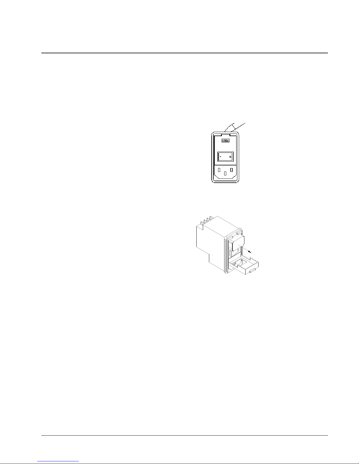
Fuse Configuration
The main fuse(s) on the AVERY DENNISON 686 / 686 HT are located inside the
AC entry. The entry has a fuse drawer that holds the fuse(s) and selects the
appropriate line voltage. If the voltage in the window DOES NOT match the AC
line amplitude intended to be supplied to the printer, DO NOT plug the power cord
in. Reconfigure as follows:
1) Using a flat blade screwdriver, open the AC entry by lifting the tab just above
the voltage indicator window.
AC Entry
2) Remove the red fuse drawer.
3) Remove all fuses and the fuse jumper if it is present.
4) Insert into the fuse drawer the correct number and style of fuse(s) and fuse jumper
for your application.
Configuration Number One: Line voltage within the range of
(See 115VAC Fuse Placement) 90 - 132VAC @ 50 - 60Hz
1) Install one 990689 – 6.25A 250V Fast Acting 1/4 x 1 1/4"
2) Install one Fuse Jumper
Users Manual Model 686 / 686 HT Printer Setup •••• 11
Page 14
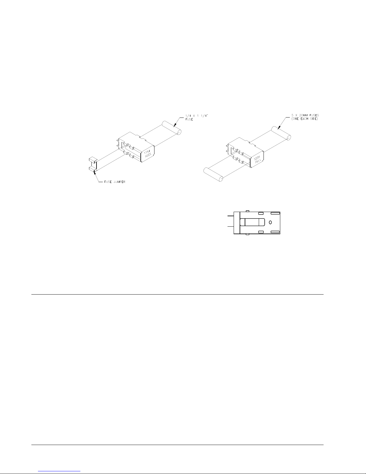
Configuration Number Two: Line voltage within the range of
A
(See 230VAC Fuse Placement) 180 - 265VAC @ 50 - 60Hz
1) Install two 990757 6.0A 250V Fast Acting 5 x 20MM
NOTE: The fuse jumper must be removed to install both 5 x 20mm fuses.
115VAC Fuse Placement 230VAC Fuse Placement
C
B
5 X 20MM Fuse Placement
5) Reinsert the fuse drawer into the AC entry with the desired voltage up.
6) Close the AC entry and verify the correct voltage is now visible.
P.C. Board Identification
Mother Bd. (371170) - Horizontal on bottom
Front Panel Bd. (511108) - User interface system
686 Thermal Control Bd. (371105NE) - AT Slot 2
686 HT Thermal Control Bd. (371105HT) - AT Slot 2
Head Driver Bd. (341106NE) - AT Slot 1
686 Ink Drive Bd. (551105) - Back of upright frame
686 HT Ink Drive Bd. (551105HT) - Back of upright frame
The fuses must be between points A and B as shown not B and C.
of printer
12 •••• Printer Setup Users Manual Model 686 / 686 HT
Page 15
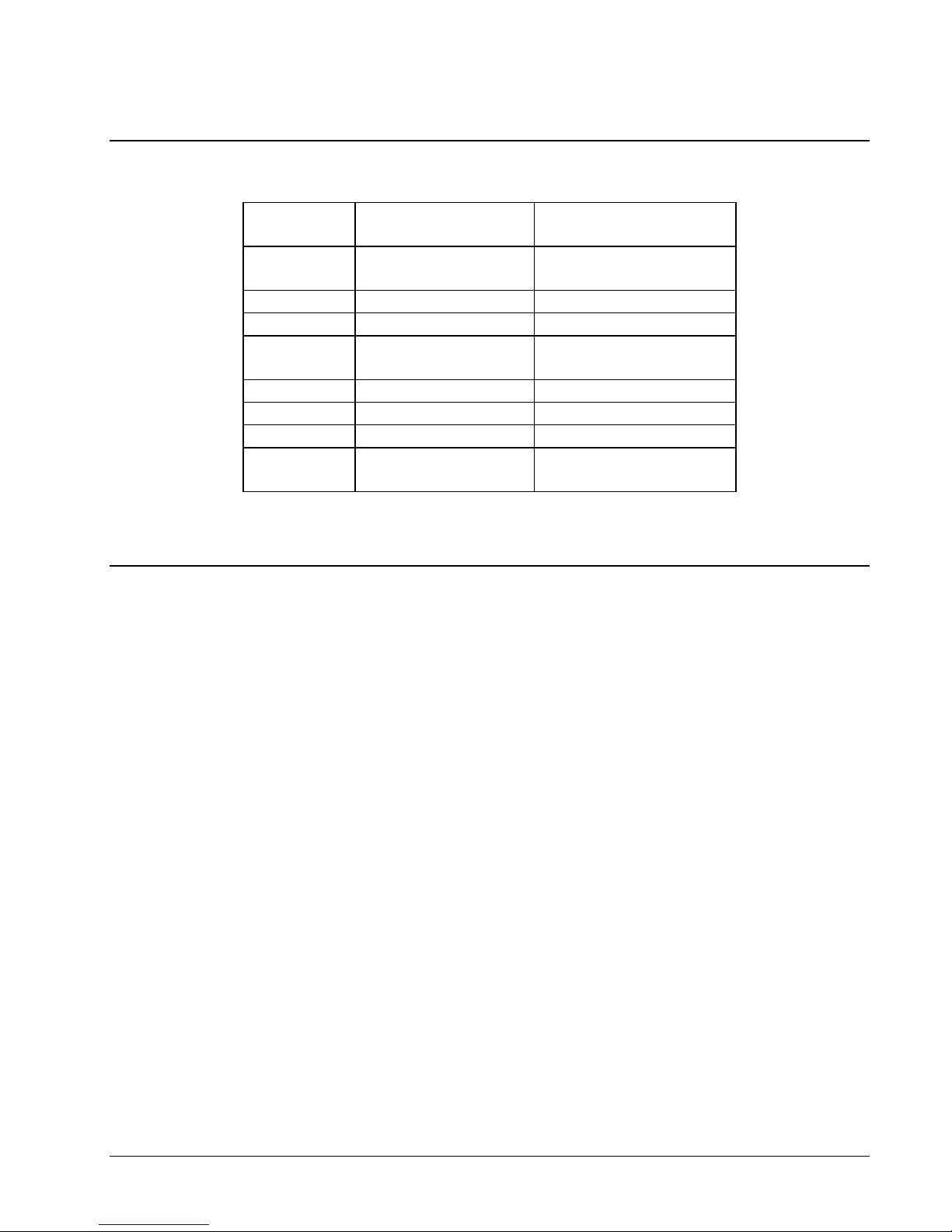
TCB Dip Switch Settings
DIP
DEFINITION 686 / 686 HT
SWITCH #
8 DOWNSTACKER/
LOKPRINT
7 UNUSED OFF
6 UNUSED OFF
5 STACKER JAM ENABLE ON
4 MACHINE TYPE ON
3 MACHINE TYPE ON
2 UNUSED ON
1 PRINTHEAD DPI ON – 300 DPI
Installing the Power Cord
DOWNSTACKER ON
LOKPRINT® OFF
DISABLE OFF
N/A OFF
A power cord is shipped with each printer. The cord for 115-volt printers will use
the standard three-prong plug used in the U.S.A. All other power configurations are
the customer’s responsibility to have the plug and alteration work done by a certified
electrician. AVERY DENNISON supplies printers to many countries with many
variations. Therefore we leave this to the customer to make the proper selection for
their country.
Users Manual Model 686 / 686 HT Printer Setup •••• 13
Page 16

Installing the PC Interface Cable
The 686 / 686 HT requires a 9-pin RS232 cable. This cable is provided with the
printer. If the cable was not found, it can be ordered from AVERY DENNISON
(Part number 351124).
The male end of the cable should be connected to the 9-pin D-shell female connector
that is located on the right side of the printer at the TCB (refer to the P.C. Board
Identification section in this manual). The female end of the cable is made to fit a 9pin male RS232 connector on the back of a PC. In case a 9 pin serial port is not
available - a 9 to 25-pin converter is also shipped with all printers.
Installing the PC Software
The software to drive the AVERY DENNISON family of printers is covered in
separate documentation. The "PcMate Platinum" software to create formats on site
for the AVERY DENNISON 686 / 686 HT printer is a Windows application. The
original "Selfform" will not create formats for the 686 / 686 HT. The new " PcMate
Platinum" package is capable of creating formats for all AVERY DENNISON
control printers.
PcMate Plus version 3.22 or above must be used to drive the 686 / 686 HT.
The printer is also capable of operating directly from a mainframe when using the
RS232 interface and AVERY DENNISON's PCL command language. (See AVERY
DENNISON PCL Command Language Manual)
14 •••• Printer Setup Users Manual Model 686 / 686 HT
Page 17
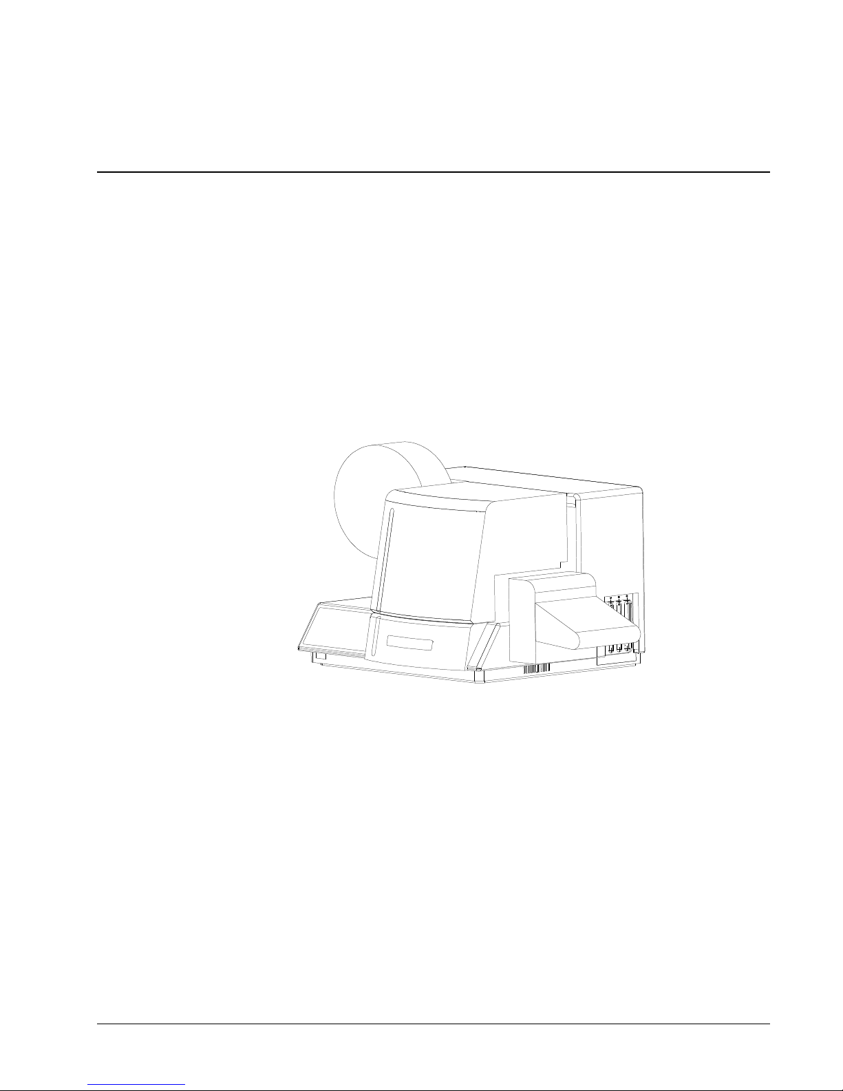
Product Description
Printer Description
The AVERY DENNISON model 686 / 686 HT thermal printer (See Figure 4) is an
electronic printer that can print on Card Stock, Size Stickers, and Pressure Sensitive
rolled stocks. The printer interfaces to a computer or a mainframe system thus
allowing electronic data input or even custom design of labels with AVERY
DENNISON’S “PcMate Platinum" program. This printer can generate a complete
tag printed on one side.
• Design your own labels on a PC
• Computer interface = IBM Compatible
• Mainframe direct interface
• RS232 9 Pin D shell female Serial interface connector
Figure 4 - AVERY DENNISON Model 686 / 686 HT Label Printer
Users Manual Model 686 / 686 HT Product Description •••• 15
Page 18

Personal Computer Specifications
This specification describes the hardware and application software requirements for
the Personal Computer that is used to download to the AVERY DENNISON 686 /
686 HT Printer.
The AVERY DENNISON 686 / 686 HT Printer uses a Windows version of
“PcMate Platinum”. This application will create the tag or label formats (layouts)
then fill and transfer data to the printer through the serial port of the computer.
When using PCMate™ Platinum 5.0, the following minimum system requirements is
highly recommended:
• IBM® PC or Compatible
• Microsoft Windows® 2000, XP or later
• 256 Megabytes of RAM
• At least 4 Gigabyte of available disk space
• Pentium III or later processor, 800Mhz minimum
• CD ROM drive
DISK DRIVES: You will need a hard disk with at least 4 Gigabytes of free disk
space to store the PCMate™ Platinum program. Additional space will be required to
store designs, print files, etc.
COMPATIBILITY: This application supports the conversion and use of basic tag
and label layouts and print files created with PCMate™ for DOS, and earlier
versions of PCMate™ for Windows. When importing tag and label layouts (designs)
from older versions of PCMate™ caution should be taken due to a chance that
feature changes and enhancements in your current version of PCMate™ Platinum
may require field modifications within the imported design
Refer to your specific software package for proper installation procedures.
16 •••• Product Description Users Manual Model 686 / 686 HT
Page 19

Printer Specification
Print method: Thermal transfer, one sided, near edge printhead printer for tags and pressure sensitive
labels.
Speed - up to 12 IPS (305mm/second) - 7"(178mm), 10"(254mm), & 12"(305mm)
Label Size Max: 686 - Up to 5.125" (130.2mm) web x up to 7" (177.8 mm) feed - cut and stacked
686HT - Up to 3.00" (76.2mm) web x up to 7" (177.8 mm) feed - cut and stacked
Transfers tested as of June 9, 2006
- Up to 14.0" (355.6mm) feed w/ Rewind
Min: 1" (25.4mm) web x 1" (25.4mm) feed at speeds of 7"(178mm) or 10"(254mm) – using
the standard 558091 Stacker.
Min: 1" (25.4mm) web x 1.250" (31.75mm) feed at speeds of 12"(305mm) or when using the
High Volume Stacker at any speed.
Print Area Max: up to 5" (127mm) web x up to 13.875" (352.4 mm) feed
Min: None
Resolution 300 DPI x 300 DPI
Fonts - Six scalable fonts resident: condensed, standard, and bold typefaces, upper and lower case
- 4pt up to 96pt (300 DPI)
- All rotations 0°, 90°, 180°, 270°
Logos - No restriction on number or size per tag (up to maximum image area)
- All rotations 0°, 90°, 180°, 270°
Care
Symbols
Justification Left, Right, and Center - field selectable
Stock Support for blank or pre-printed card stock and blank or pre-printed pressure sensitive
Interface AVERY DENNISON PCL via RS232 serial port - 9 pin D-shell
Control Panel Push-button printer function with 2 Line x 24 Character International LCD Backlit Display
Dimensions 16.0" (406.4 mm) high x 27" (685.8 mm) wide
Weight 57 Lbs. ( 26Kg.)
Electrical 90-132 / 180-265 VAC 50-60Hz 10Amp - Switch selectable
Temperature
Humidity 5% to 90% non-condensing
- Full Ginetex Care Symbol set and full NAFTA / ASTM Care Symbol Set
- Fully Scaleable
- All rotations 0°, 90°, 180°, 270°
Including stacker x 18.5" (469.9mm) deep
41°F (5°C) to 104°F (40°C)
Users Manual Model 686 / 686 HT Product Description •••• 17
Page 20

Other
Features
- Downloading of information while printer is operating
- Sequenced Fields
- Time / Date Stamping
- Life Counts
- Operator adjustable: strobe, cut position, print position, baud rate, and buffer size
- Error Detection of: stock out, ink out, print head open, full stacker, stacker jam, and print
head over-temperature
- Display: labels left to print in a batch, batch ID, total life inches, total life cuts
- Self Diagnostics
- Missed sense mark detection and correction
- Slot, Notches, Hole or Reflective registration detection
Ink Ribbon AVERY DENNISON standard thermal colors and widths
Options - SV-100 Barcode Verifier System
- Rewind Unit
- Reflective Sensor (Back of web)
- PcMate Platinum
- Spare Parts Kit
- International Hardware Kit
18 •••• Product Description Users Manual Model 686 / 686 HT
Page 21

Printer Operation & Quick Set-Up
Loading Ink
INK ROLLER
(NOT SUPPLIED IN 686 HT)
TRANSFER STOCK
FIXED
TURNBAR
INK UNWIND
TAG STOCK
FIXED
TURNBAR
Figure 5 - Ink Threading Path
The ink ribbon comes packaged in a plastic bag. For best results, leave the ink
ribbon wrapped in this bag until you are ready to use it in the printer. Use the
procedure and diagram above for loading the ink.
1) Unwrap the ink ribbon and put it on the ink-ribbon unwind arbor (See Figure 5)
by pressing it on to the arbor when the three slots are lined up.
ADJUSTABLE
TURNBAR
WEB GUIDE
686
686 HT
PRINTHEAD
ADJUSTABLE
TURNBAR
DRIVE
KNIFE
Users Manual Model 686 / 686 HT Printer Operation & Quick Set-Up •••• 19
2) Make sure the ink ribbon comes off the roll in the direction shown above and is
threaded as illustrated.
NOTE: A new ink ribbon has a leader that makes it easier to use when threading the
ribbon through the print area.
3) Put an empty ink-ribbon take-up core on the ink rewind arbor. The ink take-up
core must be at least as wide as the ink supply. The adhesive on the supply roll
of ink can be used to fasten the leader to the rewind core.
4) Advance the ink until ink starts to wrap around the take-up core.
5) You should rotate the ink arbors to keep excess slack ink from between the print
head and the ink cores.
NOTE: Make sure that the ink-ribbon take-up core and the ink-ribbon supply roll
are against the ink backer plate so that the ink ribbon tracks straight through
the print station.
Page 22

Loading Stock
TRANSFER STOCK
FIXED
TURNBAR
INK ROLLER
(NOT SUPPLIED IN 686 HT)
INK UNWIND
TAG STOCK
FIXED
TURNBAR
ADJUSTABLE
TURNBAR
FIGURE 6 – Tag Stock / Transfer Threading
Loading Stock for the First Time
1) Adjust the unwind width wider than the roll of stock to be loaded. Set the
ADJUSTABLE
TURNBAR
KNIFE
WEB GUIDE
686
686 HT
PRINTHEAD
DRIVE
stock roll on the unwind - between the guides with the stock unwinding
from the top clockwise. Adjust the unwind width down to the stock size
without clamping the core.
20 •••• Printer Operation & Quick Set-Up Users Manual Model 686 / 686 HT
2) Adjust the web guides to a width wider than the stock.
3) Remove the tape or pull the glued end of the stock loose from the supply
roll of stock. Pull off about 2 feet (.5 m) of stock to thread it through the
printer.
NOTE: If the end of the material was glued down, cut off all material that has
glue on any surface. Do not feed sticky adhesive or rough surfaces
through the printer because they can damage the print head.
4) Open the hinged cover to the printer.
5) When the printer stops, the platen roller under the print head will rotate
open enough to slide the stock through without opening the head assembly.
This has been designed for quick & easy loading without splicing on new
rolls. If for some reason the roller doesn't provide easy passage, open the
print head upper assembly by rotating the knob.
NOTE: Platen roll in 686HT will not rotate open
Page 23

Decurler / Turnbar
6) Open the print head by turning the knob.
7) After looping the leading edge of the stock over the two-decurler bars, slide
it through the web guides.
8) As the stock exits the web guide, continue to slide the stock through the
print station.
9) Push the stock until it touches the blue roller.
10) Clear all errors on the front panel. Push and hold the upper feed button to
move the stock through the drive, knife, and into the stacker. The bottom
feed button can be used to reverse the stock if necessary.
• 686-HT you must open the feed and push the material through – there
is no feed button
11) Check that the stock is center and tracking straight through the printer.
Adjust as needed.
12) Adjust the web guides on the decurler and web guides down to the edges of
the stock without deforming the stock.
Users Manual Model 686 / 686 HT Printer Operation & Quick Set-Up •••• 21
The 686 / 686 HT printer is equipped with an adjustable turn bar system to allow
optimum adjustment of multiple supplies in an effort to control flatness through the
printer.
The system consists of one large diameter (1.125 Dia.) fixed position roller and two
smaller (.500 Dia.) turnbars. One turnbar is fixed; the other is horizontally
adjustable. Web guide supplies at the start of the roll require less de-curl than
narrow web or end-of-roll supplies. The adjustable roll is equipped with wrench
flats to allow loosening so it can be moved in its mount key slot.
• Web tension is not required on the 686-HT
• By-pass the turnbar shafts to avoid damage to the transfers
Page 24

Butt Splicing Stock
NOTE: DO NOT RUN BUTT SPLICES THROUGH THE PRINT STATION.
The AVERY DENNISON 686 / 686 HT has been designed so that supplies can be
changed / replenished quickly. Removing the stock trailer remaining in the printer
and re-threading the stock altogether is quicker than butt splicing.
Web Guide Adjustment
The AVERY DENNISON 686 / 686 HT printer has been designed with only three
web guides in the printer that need to be changed as the width of the rolls change
from format to format. None of these adjustments requires any tools.
The first guide is on the unwind itself. A knob located on the front of the unwind
adjusts the width of the guides on the unwind while maintaining center justification.
To increase the width - turn the knob counter clockwise - to decrease the width, turn
the knob clockwise. Adjust the unwind width wider than the roll of stock to be
loaded. Set the stock roll on the unwind between the guides with the stock
unwinding from the top clockwise. Adjust the unwind width down to the stock size
without clamping the core. It is important not to pinch the supply roll: This is a
guide only - not a brake.
The second set of guides is center justified to the left of the print station. Close the
guides to the width of the stock using the adjustment knob. Do not pinch the stock
as it will deform the edges of the tags and can affect print registration.
The only other web guide adjustment is the stacker up-right rails (refer to the Stacker
Adjustments section in this manual). To fine-tune the location of the up-rights,
loosen the knob behind each upright rail and slide the rail in or out as needed. The
up-right rails should be located approximately 1/16" (1.5mm) to the back or front of
the label or tag as it enters the stacker.
22 •••• Printer Operation & Quick Set-Up Users Manual Model 686 / 686 HT
Page 25

Modified Drive Assembly
The spring loaded drive assembly mounted in the 686 / 686 HT printer has been
modified to prevent it from being left in the “Drive Open” position. In addition the
drive open sensor has been eliminated. The drive can be opened, if necessary, to
clear a jam or remedy other problems, but must be held in the open position.
To aid in threading, the printer is equipped with a button controlled drive system.
The buttons are on the lower right side of the front housing.
To thread the printer, the stock should be pushed through the web guide and
printhead up to and touching the bottom of the blue roller.
Clear all errors on the front panel. Push and hold the upper button to move the stock
through the drive, knife, and into the stacker. The lower button will reverse the stock
if necessary.
Flash Disk Module
The Flash Disk Module contains information that is loaded during power up only.
The Flash Disk Module may also contain logos, fonts, formats, and may even in the
future contain some operating system updates. Logos fonts and formats can be
copied to the Flash Disk Module using PCMCIA manager that is provided with
PcMate Platinum.
Users Manual Model 686 / 686 HT Printer Operation & Quick Set-Up •••• 23
Page 26
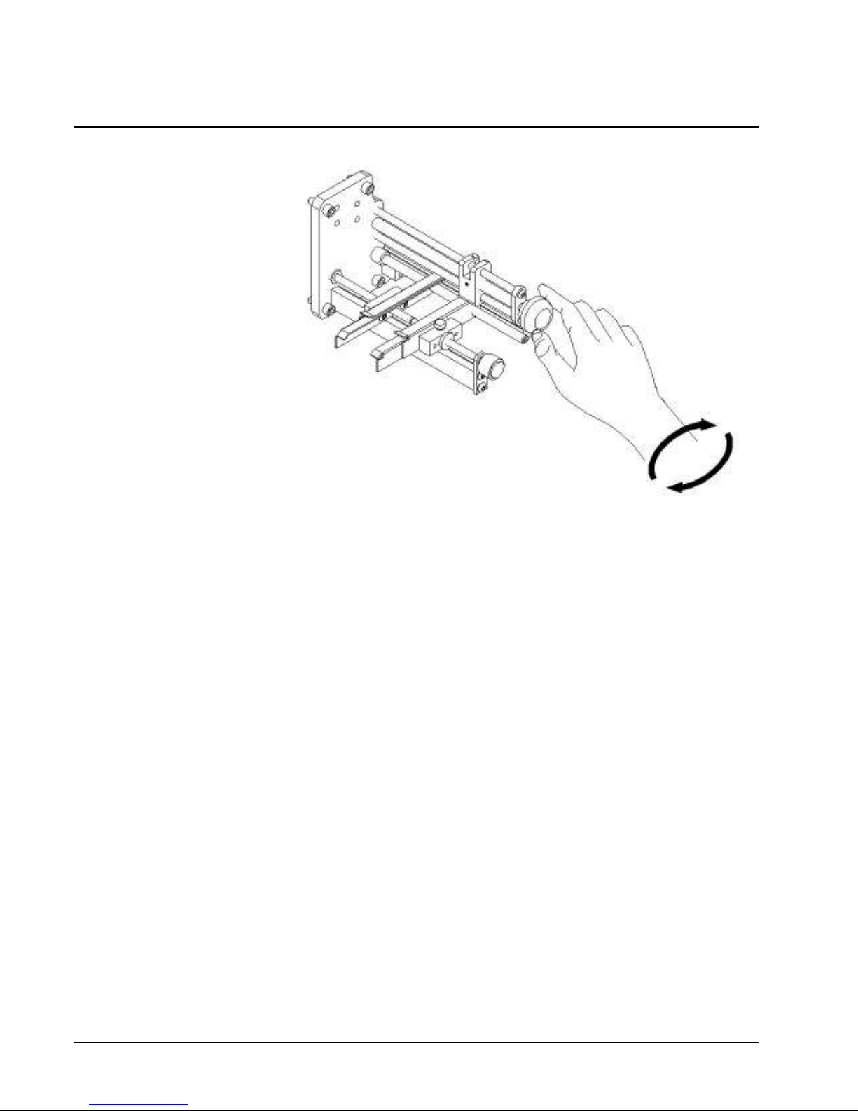
Sensor Adjustment
The hole and top reflective registration sensor can be adjusted by turning the knob as
shown above. Move the sensor over the desired registration mark. To ensure the
sensor is in the right location - hold the feed lever open and move the stock back and
forth. If the sensor LED in the front panel flashes as the hole passes through the
sensor - it is in the correct location. If the sensor LED does not flash, readjust the
sensor.
NOTE: The hole and top reflective sensor registration is selected from PC Mate
Platinum in the Design Layout Information.
See "Print Registration Sensor" for more detail.
• The 686-HT uses a top reflective setting in PcMate. The bottom part of the
sensor assembly is blocked with a metal plate for better reflection.
24 •••• Printer Operation & Quick Set-Up Users Manual Model 686 / 686 HT
Page 27
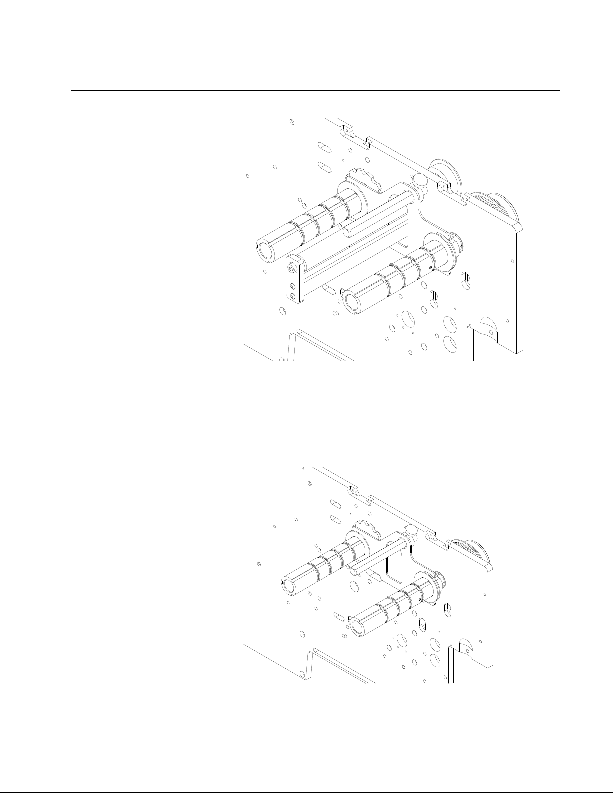
Ink Guide Adjustment
686
The ink guides on the 686 / 686 HT will move together as shown above and below.
To adjust the guides - loosen the thumbscrew and slide the ink guide into position,
then retighten the thumbscrew.
686 HT
Users Manual Model 686 / 686 HT Printer Operation & Quick Set-Up •••• 25
Page 28
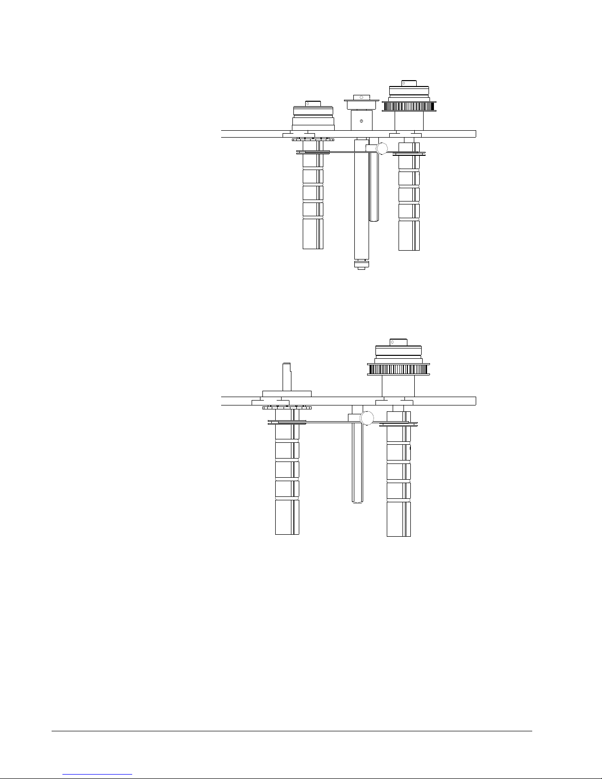
686
The ink guides must be even with each other in order for the system to work
correctly.
686 HT
26 •••• Printer Operation & Quick Set-Up Users Manual Model 686 / 686 HT
Page 29
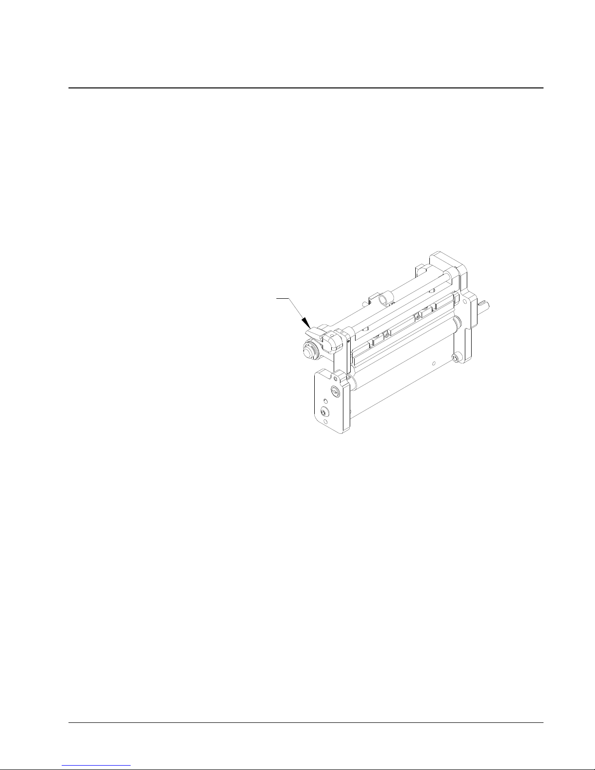
Print Head Operation
The print head module is to be opened and closed for threading the stock and ink.
The head must also be opened to clean the head and for print head replacement.
Later in the manual, under Print Head Cleaning, and Print Head Replacement,
cleaning and replacement will be covered.
The print head has an interlock switch that prevents the printer from running with the
head in the open position. If the head is open the display will read - HEAD OPEN.
WARNING: DO NOT TOUCH THE PRINT HEAD WITHOUT WEARING THE
To open the print head for threading supplies, turn knob “A” clockwise and pull out.
(See figure 7).
ANTI-STATIC GLOVES AND THE STATIC WRIST STRAP.
A
Figure 7 - Print Head Operation
To close the head mount plate, pull the knob out and lower the head assembly. Turn
knob “A” counterclockwise to its original position as shown above.
Users Manual Model 686 / 686 HT Printer Operation & Quick Set-Up •••• 27
Page 30
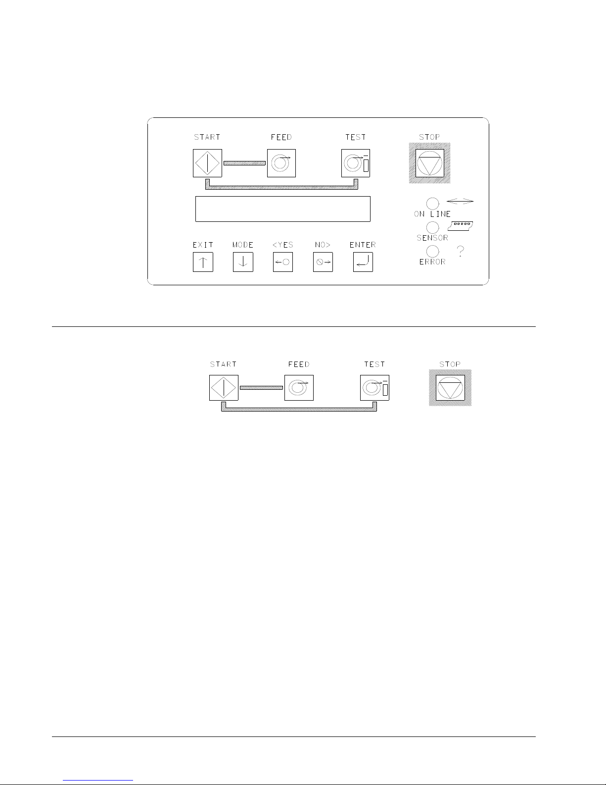
Control Panel Operation
Control Buttons
Start
- Starts the printer.
- ON LINE light must be GREEN.
(Batches downloaded to be printed)
Feed
- FEED and START must both be used.
- Feed will stop when the buttons are released.
- Labels between the head and knife will be cut and stacked as finished
labels.
- Stock moves through in one continuous strip.
- Stock moves through without printing.
- Ink will not advance; ink save on the 686 / 686 HT will automatically be
activated.
- The print head must be closed.
28 •••• Control Panel Operation Users Manual Model 686 / 686 HT
Page 31
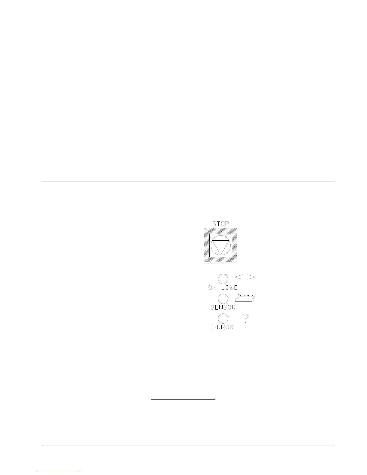
Test
Stop
Indicator Lights
- TEST and START must both be used.
- Test will stop when the buttons are released.
- Labels between the head and knife will be cut and stacked as finished
labels.
- Stock moves through in one continuous strip.
- Stock moves through with test pattern printing.
- The ink will advance with the stock.
- The print head must be closed.
- The stop button will stop the printer at the end of the current label being
printed.
The AVERY DENNISON 686 / 686 HT has three Indicator lights. These lights are
used along with the LCD display to tell the operator the current status of the printer.
On Line
Users Manual Model 686 / 686 HT Control Panel Operation •••• 29
OFF
- Has not been powered on.
- Is in its power - up sequence.
- Failed the system test.
After Power Up Sequence:
- Printer is running.
Page 32
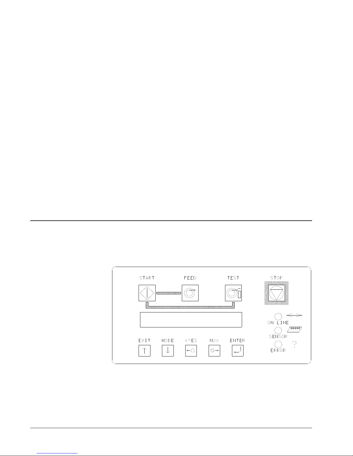
Sensor
Error
ORANGE
- System is operational.
- Ready for batches to be downloaded.
GREEN
- Batches to print, ready to start.
GREEN = "C" SENSOR
- Printer is stopped, - light is on, - sensor is setting over a stock sensor
mark hole.
- Flashing light while the printer is running, - the sensor is in-line with the
registration HOLES.
ORANGE = REFLECTIVE SENSOR
- Flashing light while the printer is running, - the sensor is in-line with the
registration PRINTED MARKS.
ORANGE
- System inter-lock triggered, see display for error.
LCD Display
The LCD display is a 2 line, 24 character, with back lighting feature for easy
readability. The first line of the display in most cases will be a prompt or question.
The second line is the response.
30 •••• Control Panel Operation Users Manual Model 686 / 686 HT
Page 33
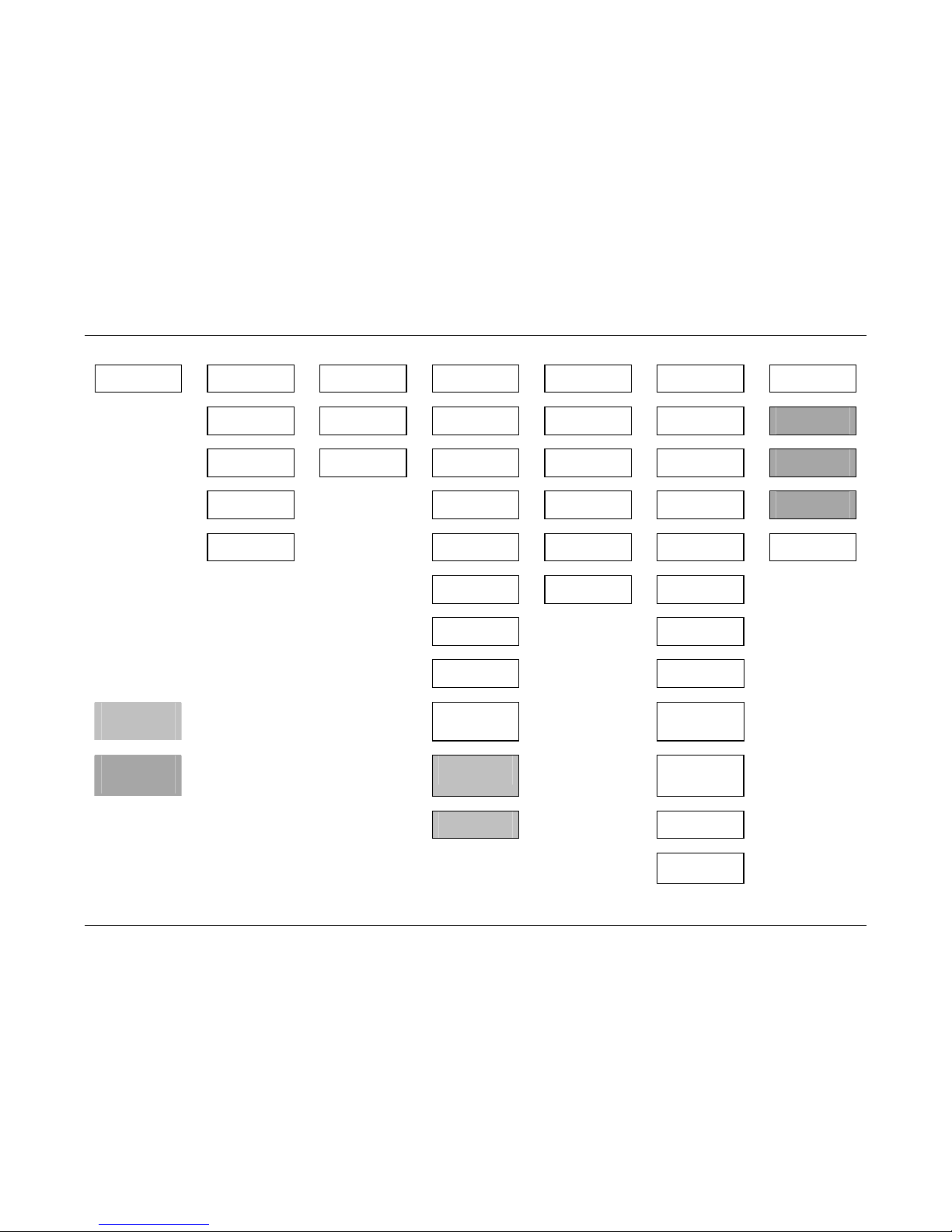
Users Manual Model 686 / 686 HT Control Panel Operation •••• 31
Front Panel Menu Map
Ready For Batches Print/Cut Positions Print Head Setup Calibrate Sensors
Life
Counts/Versions
Feature Setup Verifier Setup
Print Checkout
Format
Change Head
Strobe
Hole / Slot In
Sensor
Label Counter
Cutter Is Enabled
Print Verifier
History
Print Position
Change Head
Category
Hole / Slot Not In
Sensor
Total Labels
Produced
Emulation Mode:
Print Verifier
Setup
Change Cut
Position
Top Refl Over
Mark
Total Inches Of
Stock
Default Transfer
Type
Clean Scan
Memory
Test Head Lift
Top Refl Not Over
Mark
Controller Version
Language:
Verifier Is
Enabled
Bot Refl Over
Mark
Imager Version
Protocol:
Bot Refl Not Over
Mark
Baud Rate:
Stacker Blocked
Change Date and
Time
Not Available
when Hi-Cap
Stacker is disabled
Stacker Not
Blocked
Inksave Is Enabled
Only available
with VL70
Verifier
Stacker 2 Blocked
Print Speed
Must set to 5 IPS
for 686HT
Stacker 2 Not
Blocked
Hi Capacity
Stacker is Enabled
Flagging Mode
Page 34
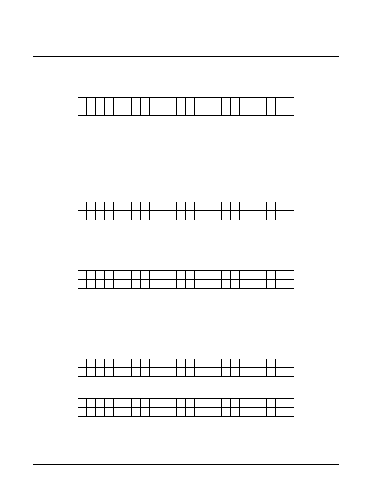
Front Panel Power Up / Home Screens
POWER UP (DIAGNOSTICS TESTS)
D I A G N O S T I C T E S T 1
This screen is displayed while the Front Panel is initializing and waiting for the
Thermal Control Board (TCB) response. While this screen is displayed the code will
check the functionality of the LED's and the display. Each state of the LED's will be
checked - (orange, green, amber and off). The LCD is checked by writing a
character to the display, checking for communications and then reading the character
back and comparing with the code. If an error occurs, the code will halt the
diagnostic test and blink the ERROR LED.
The keypad is also checked during DIAGNOSTIC TEST 1. Each key is tested to see
if it is stuck on. If a fault condition is detected, the test is halted and the screen will
display the first error key found with the following display:
( B U T T O N N A M E ) K E Y S T U C K
The (BUTTON NAME) will be one of the push button names on the front panel START, FEED, TEST, STOP, EXIT, MODE, <YES, NO>, OR ENTER.
D I A G N O S T I C T E S T # # #
T C B V E R S I O N 0 0 . 0 0
HOME SCREEN
R E A D Y F O R B A T C H E S
6 8 6 / 3 0 0
B A T C H I D
P C L 0 0 1 1 0
When the code has finished the above tests, the code will attempt to communicate
with the Thermal Control Board (TCB).
This screen will be updated with diagnostic numbers as the TCB and AT go through
different stages of PowerPC initialization.
The diagnostic test screen will also be displayed when the Diagnostic tests that are
runable from the front panel are being executed.
Once the diagnostic tests are complete, the Front Panel should display the HOME
screen.
OR
Q U A N T I T Y
32 •••• Control Panel Operation Users Manual Model 686 / 686 HT
Page 35

When the printer is powered up and all initializations are complete, if there aren’t
T P A T T E R N
any Batches to print, the "HOME" screen will be "READY FOR BATCHES" and
the model and print head density.
When there are Batches to be printed, the "HOME" screen will be the "BATCH ID
QTY" screen. The Batch ID / Batch Qty screen displays the currently cutting batch
ID and labels remaining to be cut.
When the Batch ID / Qty screen is the home screen and the user presses the EXIT
button - the Model and DPI are displayed briefly before the Batch Id / Qty screen is
displayed.
If the printer is performing a FEED or a TEST pattern, the screen will show
"FEEDING" or "PRINTING TEST PATTERN" respectively on line two, the top line
will be blank
F E E D I N G
P R I N T I N G T E S
Users Manual Model 686 / 686 HT Control Panel Operation •••• 33
Page 36
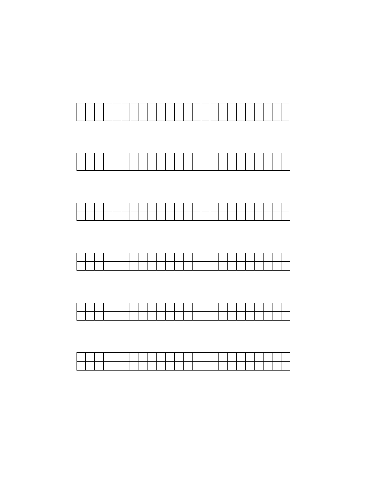
Pressing the MODE / Down Arrow key will take the user to the various mode
screens listed below (refer to the Front Panel Mode Descriptions section in this
manual).
Pressing the EXIT / Up Arrow key at any time will take the user back to the
"HOME" screen.
PRINTER ADJUSTMENTS
P R E S S E N T E R F O R
P R I N T / C U T P O S I T I O N S
PRINTHEAD ADJUSTMENTS
P R E S S E N T E R F O R
P R I N T H E A D S E T U P
CALIBRATE SENSORS
P R E S S E N T E R F O R
C A L I B R A T I N G S E N S O R S
LIFE COUNTS / VERSIONS
P R E S S E N T E R F O R
L I F E C O U N T S / V E R S I O N S
SETUP SCREEN
P R E S S E N T E R F O R
F E A T U R E S E T U P
VERIFIER SETUP SCREEN
P R E S S E N T E R F O R
V E R I F I E R S E T U P
34 •••• Control Panel Operation Users Manual Model 686 / 686 HT
Page 37
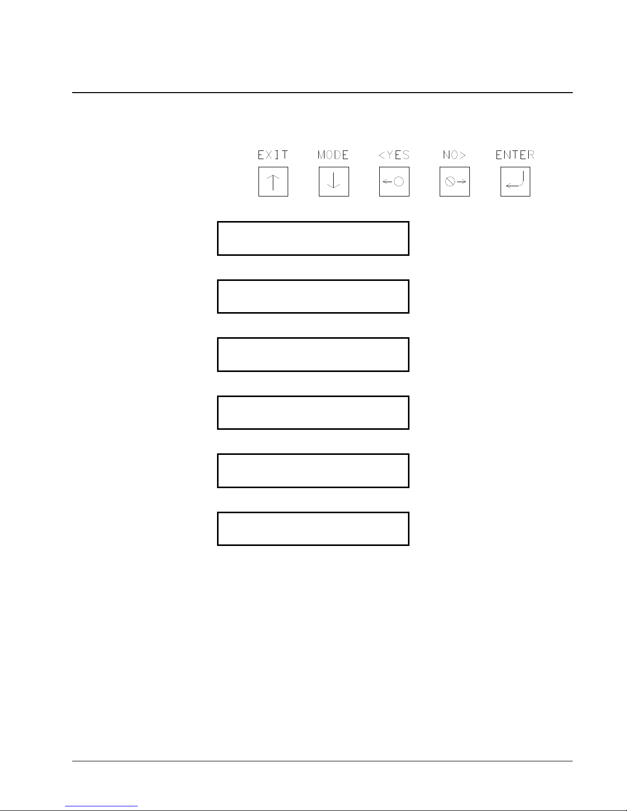
Front Panel Mode Descriptions
There are six (6) main mode levels that are selected and modified using the
following function keys:
Use the MODE ↓ key to move through the main mode screens shown below:
PRESS ENTER FOR
PRINT / CUT POSITIONS
PRESS ENTER FOR
PRINT HEAD SETUP
PRESS ENTER FOR
CALIBRATING SENSORS
PRESS ENTER FOR
LIFE COUNTS / VERSIONS
PRESS ENTER FOR
FEATURES SETUP
PRESS ENTER FOR
VERIFIER SETUP
Use the EXIT ↑ to move to the HOME screens.
Users Manual Model 686 / 686 HT Control Panel Operation •••• 35
Page 38
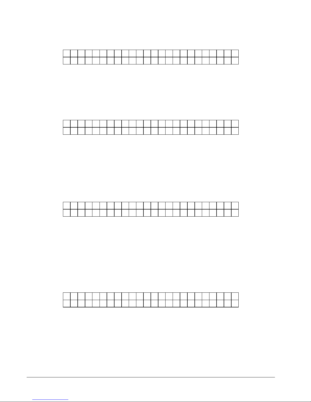
PRINT / CUT POSITIONS
P R E S S E N T E R F O R
P R I N T / C U T P O S I T I O N
P R E S S E N T E R T O
P R I N T C H E C K O U T F O R M A T
This screen follows the "BATCH ID / BATCH QTY" screen if there are batches to
be printed, otherwise it follows the "READY FOR BATCHES / MODEL DPI" home
screen.
Pressing ENTER will take the user to the "PRINT / CUT POSITIONS" screens.
Pressing the MODE / Down Arrow key will take the user to the "PRINTHEAD
SETUP" screen. Pressing the EXIT / Up Arrow key will take the user back to the
"HOME" screen.
This screen is the first screen under "PRINT / CUT POSITIONS". Pressing ENTER
will cause the printer to print the checkout format. The printer will setup to do the
checkout format and start printing. The front panel will remain on this screen so the
user can use the MODE / Down Arrow key to get to the printer adjustments. When
the EXIT / Up Arrow key is pressed the printer stops printing - the checkout format
and goes back to what it was doing before the checkout was requested.
Pressing the MODE / Down Arrow key will take the user to the "PRINT
POSITION" screen. Pressing the EXIT / Up Arrow key will take the user back to
the "HOME" screen.
P R I N T P O S I T I O N
V A L U E : ± X X N E W V A L U E : ± Y Y
This screen follows the "PRINT CHECKOUT FORMAT" screen. This screen
allows the print position to be adjusted in the feed direction.
The <YES / NO> buttons are used to change the new print value. The value is
displayed in a positive / negative format. The value ranges for XX and YY can be
from a -9 to a +9. Pressing ENTER will change the CURRENT PRINT value to the
NEW PRINT value. A more positive number will move the print to the right while a
more negative number will move the print to the left.
Pressing the MODE / Down Arrow key will take the user to the "CHANGE CUT
POSITION" screen. Pressing the EXIT / Up Arrow key will take the user back to
the "HOME" screen.
C H A N G E C U T P O S I T I O N
V A L U E : ± X X N E W V A L U E : ± Y Y
This screen follows the "PRINT POSITION" screen. This screen allows the cut
position to be adjusted. The <YES / NO> buttons are used to change the new cut
value. The value is displayed in a positive / negative format. The value ranges for
XX and YY can be from a -9 to a +9. Pressing ENTER will change the CURRENT
CUT value to the NEW CUT value. A more positive number will move the cut to
the right while a more negative number will move the cut to the left.
36 •••• Control Panel Operation Users Manual Model 686 / 686 HT
Page 39
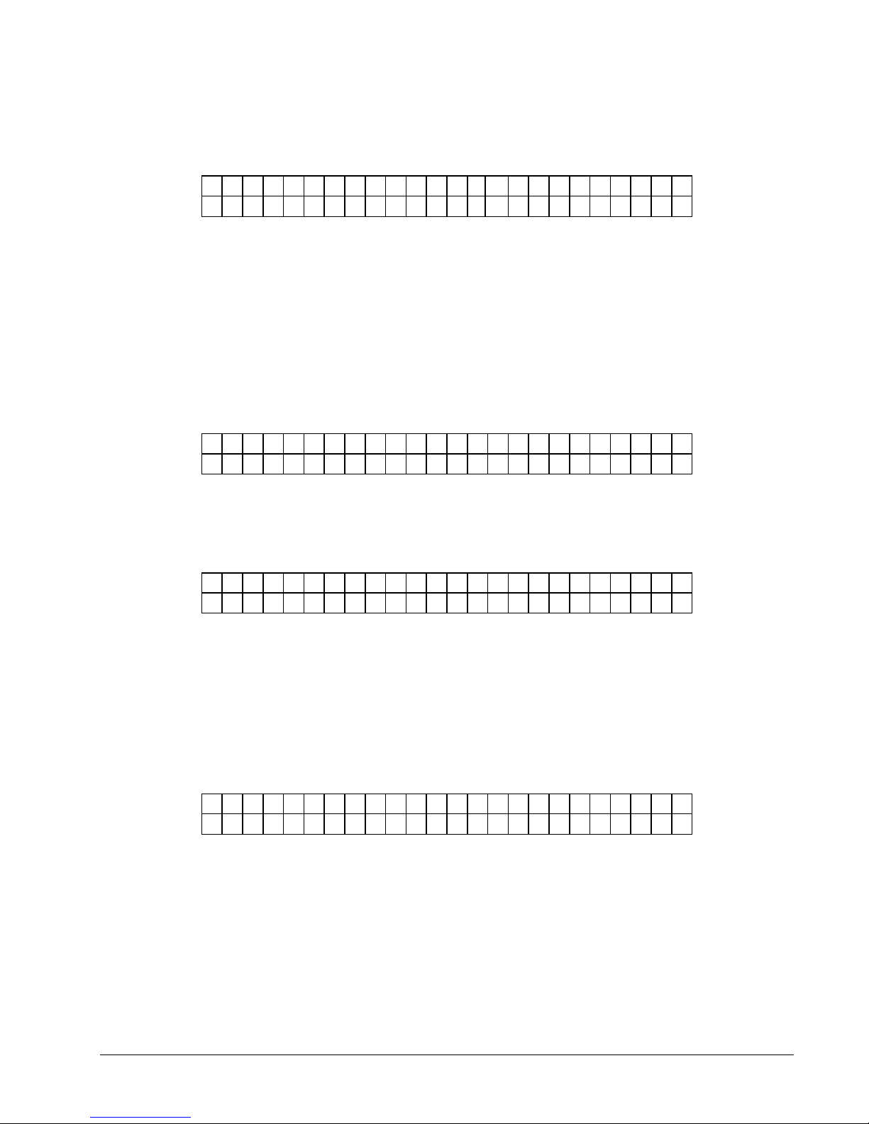
D O T S H I F T
V A L U E : ± X X N E W V A L U E : ± Y Y
PRINTHEAD SETUP
P R E S S E N T E R F O R
P R I N T H E A D S E T U P
Pressing the MODE / Down Arrow key will take the user to the "DOT SHIFT"
screen. Pressing the EXIT / Up Arrow key will take the user back to the "HOME"
screen.
This screen follows the "CHANGE CUT POSITION" screen. This screen allows the
print position to be adjusted in the WEB direction. The <YES / NO> buttons are
used to change the new shift value. The value is displayed in a positive / negative
format. The value ranges for XX and YY can be from a -16 to a +16 dots. Pressing
ENTER will change the CURRENT DOT SHIFT value to the NEW DOT SHIFT
value. A more positive number will move the print to the front while a more
negative number will move the print to the back.
Pressing the MODE / Down Arrow key will take the user back to the "PRINT
CHECK OUT FORMAT" screen. Pressing the EXIT / Up Arrow key will take the
user back to the "HOME" screen.
This screen follows the "PRINT / CUT POSITIONS" screen. Pressing ENTER will
take the user to the "PRINTHEAD SETUP" screens. Pressing the MODE / Down
Arrow key will take the user to the "CALIBRATING SENSORS" screen. Pressing
the EXIT / Up Arrow key will take the user back to the "HOME" screen.
C H A N G E S T R O B E
V A L U E : ± X X N E W V A L U E : ± Y Y
This screen is the first screen under "PRINTHEAD SETUP" screen. This screen
allows the user to adjust the strobe. The <YES / NO> buttons are used to change the
new value. The value is displayed in a positive / negative format. The value ranges
for X and Y can be from a -7 to a +7. Pressing ENTER will change the CURRENT
STROBE value to the NEW STROBE value. A more positive number will make the
print darker while a more negative number will make the print lighter.
Pressing the MODE / Down Arrow key will take the user to the "CHANGE HEAD
CATEGORY" screen. Pressing the EXIT / Up Arrow key will take the user back to
the "HOME" screen.
H E A D C A T E G O R Y
V A L U E : ± X X N E W V A L U E : ± Y Y
This screen follows the "CHANGE STROBE" screen. The screen allows the user to
enter the head category. The <YES / NO> buttons are used to change the new head
category value. The value ranges from 1 to 8. Pressing ENTER will change the
CURRENT HEAD category value to the NEW HEAD value. See the section
“PRINTHEAD REPLACEMENT” for instructions for setting the head category.
Pressing the MODE / Down Arrow key will take the user back to the "CHANGE
STROBE" screen. Pressing the EXIT / Up Arrow key will take the user back to the
"HOME" screen.
Users Manual Model 686 / 686 HT Control Panel Operation •••• 37
Page 40
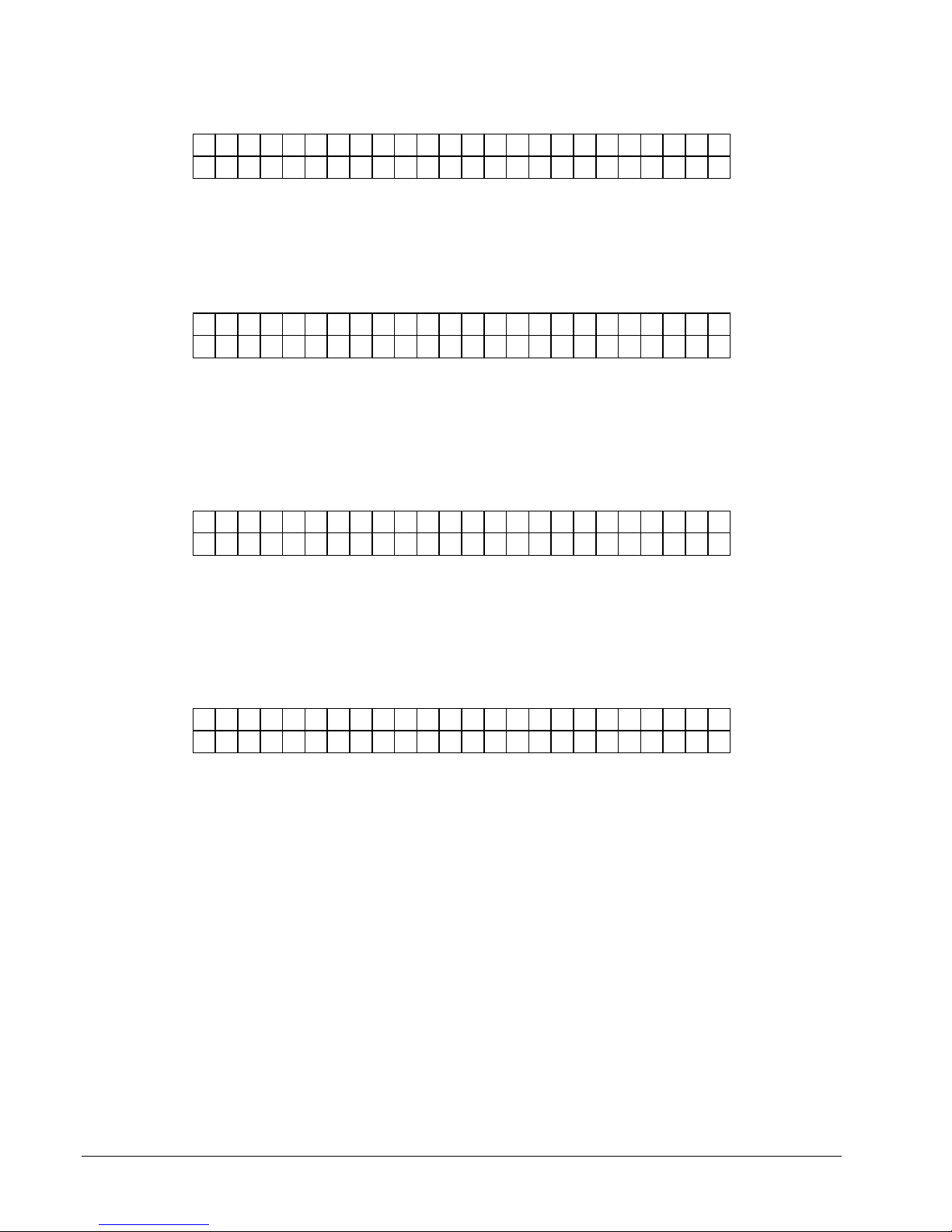
CALIBRATE SENSORS
P R E S S E N T E R T O
C A L I B R A T E S E N S O R S
H O L E / S L O T I N S E N S O R
V A L U E : 0 0 0 N E W V A L U E : 0 0 0
H O L E / S L O T N O T I N S E N S O R
V A L U E : 0 0 0 N E W V A L U E : 0 0 0
This screen follows the "PRINT HEAD SETUP" screen.
Pressing ENTER will take the user to the "CALIBRATE SENSORS" screens.
Pressing the MODE / Down Arrow key will take the user to the "LIFE COUNTS /
VERSIONS" screen. Pressing the EXIT / Up Arrow key will take the user back to
the "HOME" screen.
This is the first screen under "CALIBRATE SENSORS". Place the stock hole / slot
sense mark under the sensor. Slowly move the stock under sensor until the NEW
VALUE reading is its smallest value then press ‘Enter’.
Pressing the MODE / Down Arrow key will take the user to the "HOLE / SLOT
NOT IN SENSOR" screen. Pressing the EXIT / Up Arrow key will take the user
back to the "HOME" screen.
This screen follows the "HOLE / SLOT IN SENSOR" screen. Place the stock under
the sensor so that it blocks the sensor and when NEW VALUE is at its largest value
press ‘Enter’.
Pressing the MODE / Down Arrow key will take the user to the "TOP REFL OVER
MARK" screen. Pressing the EXIT / Up Arrow key will take the user back to the
"HOME" screen.
T O P R E F L O V E R M A R K
V A L U E : 0 0 0 N E W V A L U E : 0 0 0
This screen follows the "HOLE / SLOT NOT IN SENSOR" screen. Place the stock
under the sensor so that the reflective mark is under the sensor and when NEW
VALUE is at is largest value press ‘Enter’.
Pressing the MODE / Down Arrow key will take the user to the "TOP REFL NOT
OVER MARK" screen. Pressing the EXIT / Up Arrow key will take the user back to
the "HOME" screen.
38 •••• Control Panel Operation Users Manual Model 686 / 686 HT
Page 41
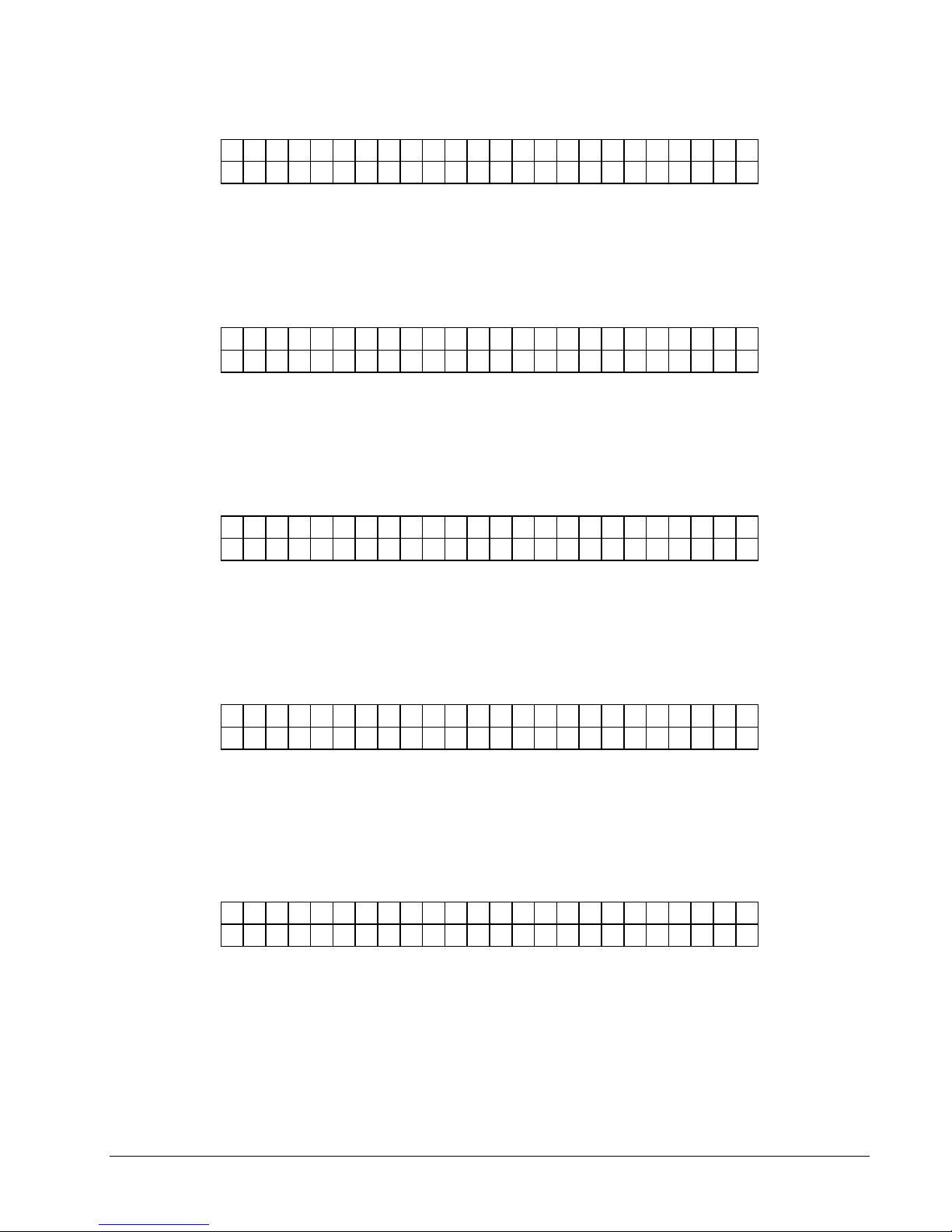
T O P R E F L N O T O V E R M A R K
V A L U E : 0 0 0 N E W V A L U E : 0 0 0
This screen follows the "TOP REFL OVER MARK" screen. Place the stock under
the sensor so that the stock is under the sensor but the reflective mark is not under
the sensor and when NEW VALUE is at is smallest value press ‘Enter’.
Pressing the MODE / Down Arrow key will take the user to the "BOT REFL OVER
MARK" screen. Pressing the EXIT / Up Arrow key will take the user back to the
"HOME" screen.
B O T R E F L O V E R M A R K
V A L U E : 0 0 0 N E W V A L U E : 0 0 0
This screen follows the "TOP REFL NOT OVER MARK" screen. Place the stock
over the sensor so that the reflective mark is over the sensor and when NEW
VALUE is at is largest value press ‘Enter’.
Pressing the MODE / Down Arrow key will take the user to the "BOT REFL NOT
OVER MARK" screen. Pressing the EXIT / Up Arrow key will take the user back to
the "HOME" screen.
B O T R E F L N O T O V E R M A R K
V A L U E : 0 0 0 N E W V A L U E : 0 0 0
This screen follows the "BOT REFL OVER MARK" screen. Place the stock over
the sensor so that the stock is over the sensor but the reflective mark is not over the
sensor and when NEW VALUE is at is smallest value press ‘Enter’.
Pressing the MODE / Down Arrow key will take the user to the "STACKER
BLOCKED" screen. Pressing the EXIT / Up Arrow key will take the user back to
the "HOME" screen.
S T A C K E R B L O C K E D
V A L U E : 0 0 0 N E W V A L U E : 0 0 0
This screen follows the "BOT REFL NOT OVER MARK" screen. Place the stock in
the stacker jam sensor so that the stock is within the sensor site path and when NEW
VALUE is at is highest value press ‘Enter’.
Pressing the MODE / Down Arrow key will take the user to the "STACKER NOT
BLOCKED" screen. Pressing the EXIT / Up Arrow key will take the user back to
the "HOME" screen.
S T A C K E R N O T B L O C K E D
V A L U E : 0 0 0 N E W V A L U E : 0 0 0
This screen follows the "STACKER BLOCKED" screen. Remove any stock from
the stacker jam sensor so that no stock is within the sensor site path and when NEW
VALUE is at is lowest value press ‘Enter’.
Pressing the MODE / Down Arrow key will take the user back to the "HOLE / SLOT
IN SENSOR" screen. Pressing the EXIT / Up Arrow key will take the user back to
the "HOME" screen.
Users Manual Model 686 / 686 HT Control Panel Operation •••• 39
Page 42
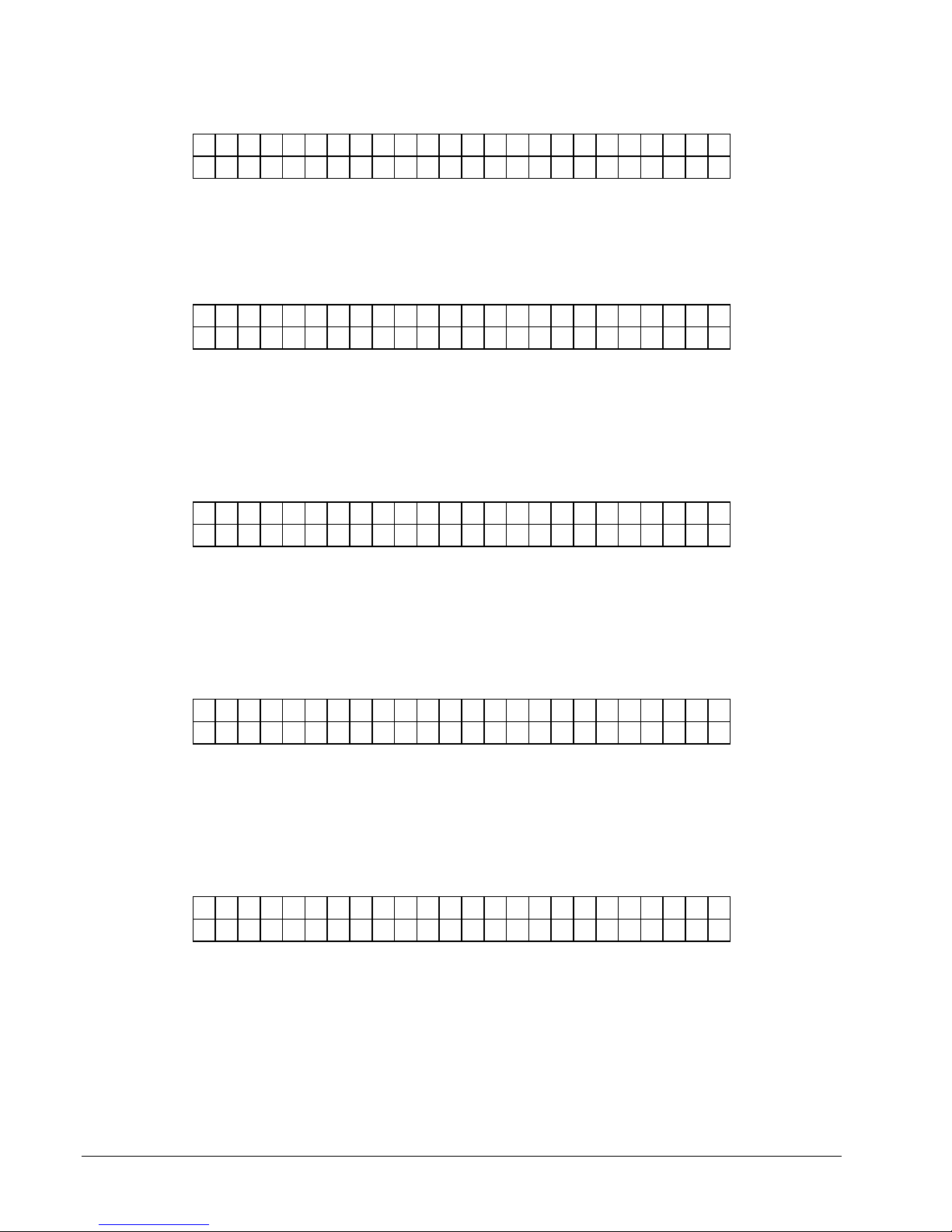
LIFE COUNTS / VERSIONS
P R E S S E N T E R F O R
L I F E C O U N T S / V E R S I O N S
This screen follows the "CALIBRATE SENSORS" screen. Pressing ENTER will
take the user to the "LIFE COUNTS / VERSIONS" screens.
Pressing the MODE / Down Arrow key will take the user to the "FEATURE
SETUP" screen. Pressing the EXIT / Up Arrow key will take the user back to the
"HOME" screen.
L A B E L C O U N T E R : 0 0 0 0 0 0
P R E S S E N T E R T O R E S E T
This screen is the first screen under "LIFE COUNTS / VERSIONS". This screen
shows total labels produced since the last counter reset. Pressing the ENTER key
will reset the counter to zero.
Pressing the MODE / Down Arrow key will take the user to the "TOTAL LABELS
PRODUCED" screen. Pressing the EXIT / Up Arrow key will take the user back to
the "HOME" screen.
T O T A L L A B E L S P R O D U C E D
0 0 0 0 0 0 0 0 0 0
This screen follows the "LABEL COUNTER" screen. This screen displays the total
labels produced since the printer was built. This counter is NOT resettable by the
user.
Pressing the MODE / Down Arrow key will take the user to the "TOTAL INCHES
OF STOCK" screen. Pressing the EXIT / Up Arrow key will take the user back to
the "HOME" screen.
T O T A L I N C H E S O F S T O C K
0 0 0 0 0 0 0 0 0 0
This screen follows the "TOTAL LABELS PRODUCED" screen. This screen
displays the total inches since the printer was built. This value is NOT resettable by
the user.
Pressing the MODE / Down Arrow key will take the user to the "CONTROLLER
VERSION" screen. Pressing the EXIT / Up Arrow key will take the user back to the
HOME screen.
C O N T R O L L E R V E R S I O N
T C B 1 0 9 3 4
This screen follows the "TOTAL INCHES OF STOCK" screen. This screen shows
the operating system version for the controller (TCB).
Pressing the MODE / Down Arrow key will take the user to the "IMAGER
VERSION" screen. Pressing the EXIT / Up Arrow key will take the user back to the
HOME screen.
40 •••• Control Panel Operation Users Manual Model 686 / 686 HT
Page 43
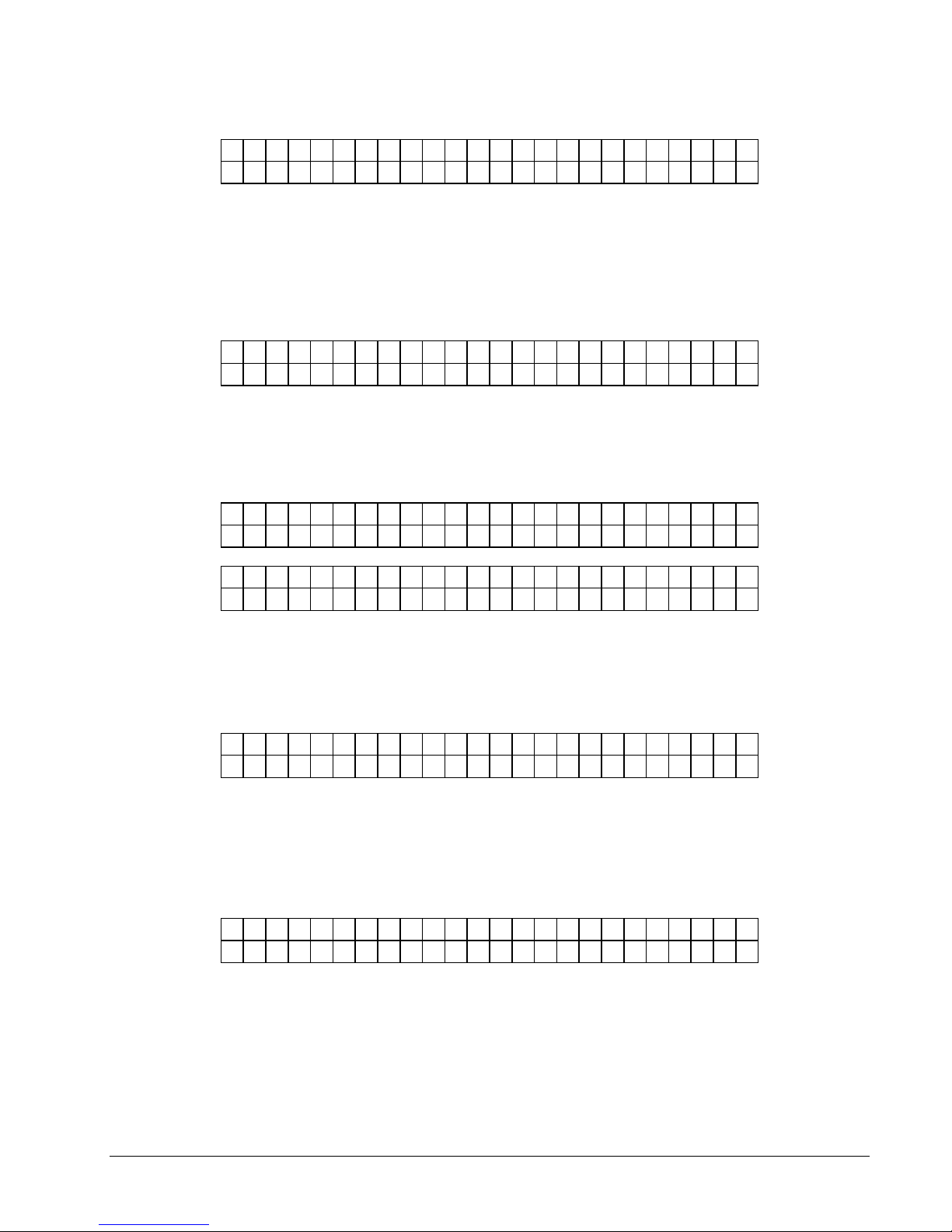
I M A G E R V E R S I O N
U S A 1 9 . 0 1
This screen follows the "CONTROLLER VERSION" screen. This screen shows
operating system version for the imager (AT).
Pressing the MODE / Down Arrow key will take the user back to the "LABEL
COUNTER" screen.
Pressing the EXIT / Up Arrow key will take the user back to the HOME screen.
FEATURE SETUP SCREEN
P R E S S E N T E R F O R
F E A T U R E S E T U P
This screen follows the "LIFE COUNT / VERSIONS".
Pressing ENTER will take the user to the "FEATURE SETUP" screens. Pressing the
MODE / Down Arrow key will take the user to the "VERIFIER SETUP" screen.
Pressing the EXIT / Up Arrow key will take the user back to the "HOME" screen.
C U T T E R I S E N A B L E D
P R E S S E N T E R T O D I S A B L E
C U T T E R I S D I S A B L E D
P R E S S E N T E R T O E N A B L E
OR
This screen is the first screen of the "FEATURE SETUP". This screen allows the
cutter to be enabled or disabled. Pressing ENTER will toggle from ENABLED to
DISABLED and vice versa. Pressing the MODE / Down Arrow key will take the
user to the "EMULATION MODE" screen. Pressing the EXIT / Up Arrow key will
take the user back to the "HOME" screen.
E M U L A T I O N M O D E : N O N E
N E W E M U L A T I O N M O D E : 6 3 0
This screen follows the "CUTTER ENABLE / DISABLE" screen. This screen
allows the EMULATION MODE to be changed. Use the <YES and NO> keys to
move between NONE, 630, and 650 modes. Pressing ENTER will update the
emulation mode with the selection after new emulation mode. Pressing the MODE /
Down Arrow key will take the user to the "DEFAULT TRANSFER TYPE" screen.
Pressing the EXIT / Up Arrow key will take the user back to the "HOME" screen.
D E F A U L T T R A N S F E R T Y P E
V A L U E : X X X N E W V A L U E : Y Y Y
This screen follows the "EMULATION MODE" screen IF emulation mode is
something other than none. This screen allows the DEFAULT TRANSFER TYPE
to be changed. This transfer type is used when the printer is in 630 or 650 emulation
mode. The 630 and 650 do not send valid 6X6 transfer types in their PCL code.
This default is used for those formats. Use the <YES and NO> keys to change the
number value at the cursor position. Pressing ENTER will update the current value
with the new value (i.e. 053 for type 53). After ENTER is pressed on the last digit
the TRANSFER TYPE on the top line will be updated. Pressing the MODE / Down
Users Manual Model 686 / 686 HT Control Panel Operation •••• 41
Page 44
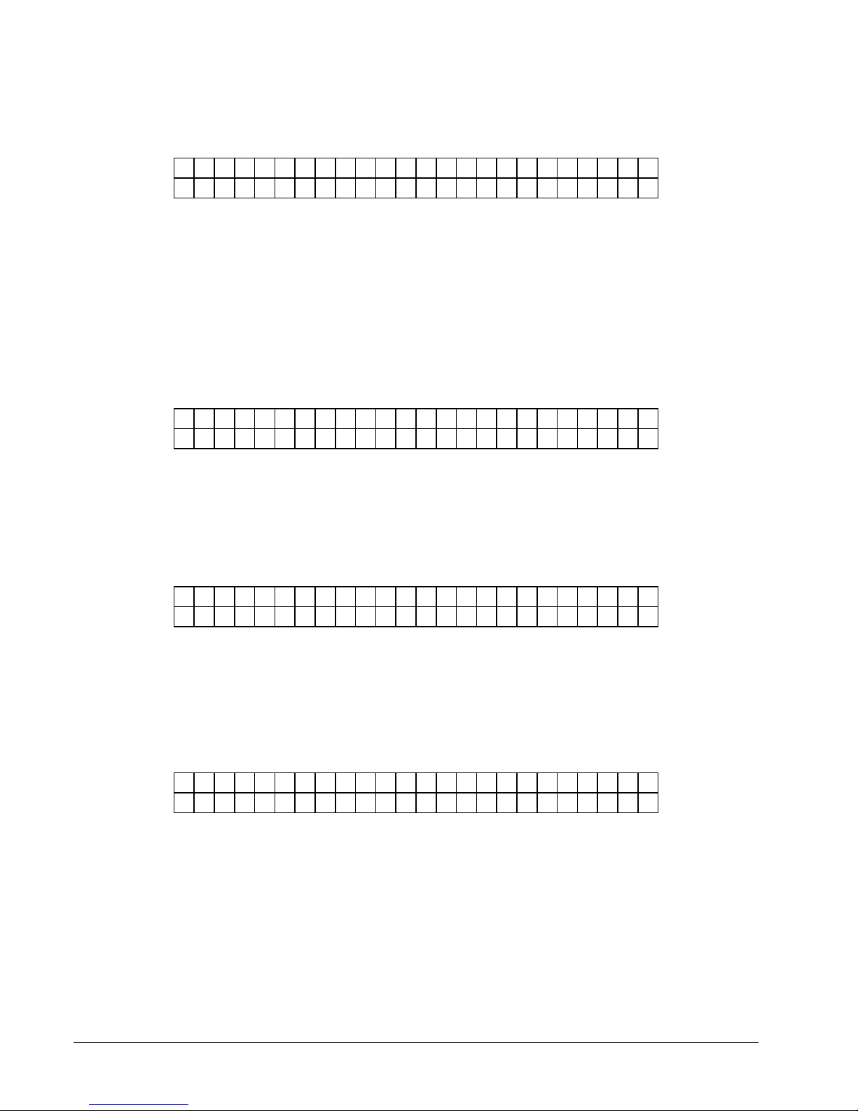
Arrow key will take the user to the "LANGUAGE" screen. Pressing the EXIT / Up
Arrow key will take the user back to the "HOME" screen.
L A N G U A G E : X X X X X X
N E W L A N G U A G E : Y Y Y Y Y Y
This screen follows the "DEFAULT TRANSFER TYPE" screen. This screen allows
the front panel display language to be changed. Use the <YES and NO> keys to
move between the supported languages on the pr1nter. Any number of front panel
languages can be stored on the Flash Disk Module (dependent on available space). If
no additional languages other than the default are available on the printer XXXXXX
and YYYYYY will be the same value. Pressing ENTER will update the display
language with the selection. Pressing the MODE / Down Arrow key will take the
user to the "PROTOCOL" screen. Pressing the EXIT / Up Arrow key will take the
user back to the "HOME" screen.
Warning: Mis-matched communication protocols may result in the inability to
communicate with the printer and / or loss of data.
P R O T O C O L : X X X X X X
N E W P R O T O C O L : Y Y Y Y Y Y
This screen follows the "LANGUAGE" screen. This screen allows the
communications protocol to be changed between the supported types. Use the <YES
and NO> keys to move between the supported protocols – RTS / CTS is considered
hardware handshaking and XON / XOFF is considered to be software. Pressing
ENTER will update the communications protocol with the selection. Pressing the
MODE / Down Arrow key will take the user to the "BAUD RATE" screen. Pressing
the EXIT / Up Arrow key will take the user back to the "HOME" screen.
B A U D R A T E : X X X X X X
N E W B A U D R A T E : Y Y Y Y Y Y
This screen follows the "PROTOCOL" screen. This screen allows the serial
communications speed to be changed. Use the <YES and NO> keys to move
between the supported speeds – typical is 9600 dependent on serial communication
cable length. Pressing ENTER will update the communications speed with the
selection. Pressing the MODE / Down Arrow key will take the user to the
"CHANGE DATE AND TIME" screen. Pressing the EXIT / Up Arrow key will
take the user back to the "HOME" screen.
C H A N G E D A T E A N D T I M E
0 3 / 1 4 / 0 0 1 2 : 0 5 P M
This screen follows the “BAUD RATE” screen. This screen allows the system date
and time to be changed. When this screen appears, the first digit of the month will
be blinking. (The date is shown in US format, MM/DD/YY.) Pressing the <YES
and NO> keys will change the digit up and down respectively. Pressing ENTER will
move to the next digit. Only the digits and the A or P in AM or PM can be changed.
When all changes are complete, pressing the MODE / Down Arrow key will take the
user to the “INKSAVE ENABLE / DISABLE” screen, and pressing the EXIT / Up
Arrow key will take the user back to the “HOME” screen. If an illegal date or time
is entered, this screen will be re-displayed with the original date or time. A valid
date and time must be entered before the user can go on.
42 •••• Control Panel Operation Users Manual Model 686 / 686 HT
Page 45
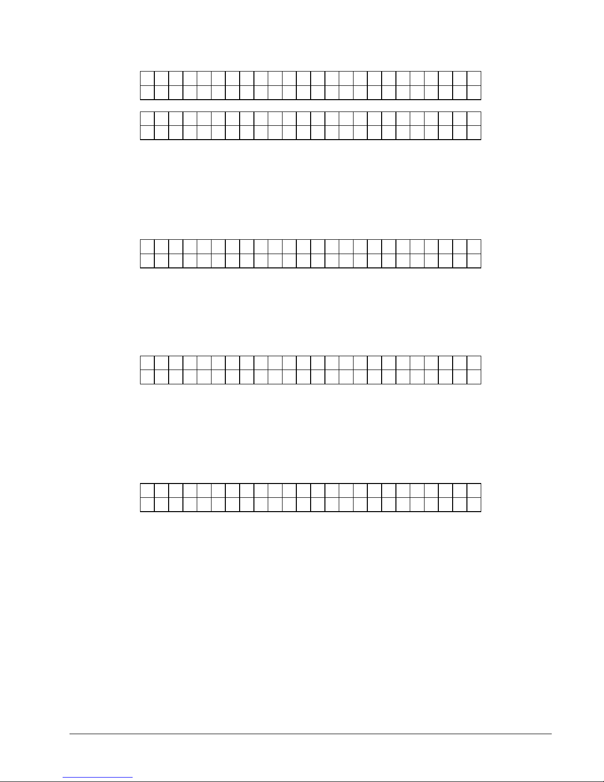
I N K S A V E I S E N A B L E D
P R E S S E N T E R T O D I S A B L E
I N K S A V E I S D I S A B L E D
P R E S S E N T E R T O E N A B L E
VERIFIER SETUP
P R E S S E N T E R F O R
V E R I F I E R S E T U P
P R E S S E N T E R T O
P R I N T V E R I F I E R H I S T O R Y
OR
This screen allows inksave to be enabled or disabled. Inksave is an option that is
available on certain models. It must be enabled in the format to operate. If inksave
is enabled in the format, it can be disabled using this screen. Pressing ENTER will
toggle from ENABLED to DISABLED and vice versa. Pressing the MODE / Down
Arrow key will take the user to the "CUTTER ENABLE / DISABLE" screen.
Pressing the EXIT / Up Arrow key will take the user back to the "HOME" screen.
This screen follows the "FEATURE SETUP" screen.
Pressing ENTER will take the user to the "VERIFIER SETUP" screens. Pressing the
MODE / Down Arrow key will take the user back to the "PRINT / CUT
POSITIONS" screen. Pressing the EXIT / Up Arrow key will take the user back to
the "HOME" screen.
Note: This screen for SV-70 Verifier only
This screen is the first screen under "VERIFIER SETUP". Pressing ENTER will
cause the printer to print a verifier history report containing bar code information for
all the problem scans since the scan memory was last cleared.
Pressing the MODE / Down Arrow key will take the user to the "PRINT VERIFIER
SETUP" screen. Pressing the EXIT / Up Arrow key will take the user back to the
"HOME" screen.
Note: This screen for SV-70 Verifier only
P R E S S E N T E R T O
P R I N T V E R I F I E R S E T U P
This screen follows the "PRINT VERIFIER HISTORY" screen. Pressing ENTER
will cause the printer to print a report containing the present verifier setup.
Pressing the MODE / Down Arrow key will take the user to the "CLEAR SCAN
HISTORY" screen. Pressing the EXIT / Up Arrow key will take the user back to the
"HOME" screen.
Users Manual Model 686 / 686 HT Control Panel Operation •••• 43
Page 46
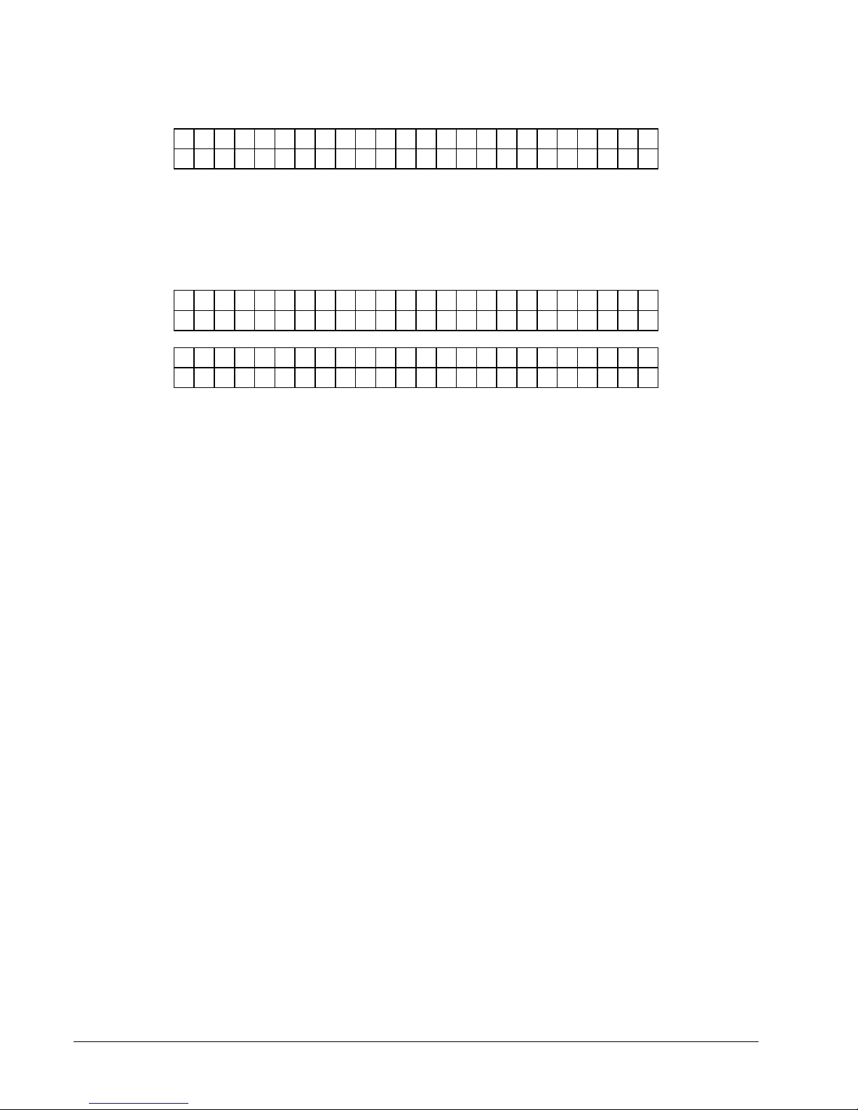
Note: This screen for SV-70 Verifier only
P R E S S E N T E R T O
C L E A R S C A N M E M O R Y
This screen follows the "PRINT VERIFIER SETUP" screen. Pressing ENTER will
clear the verifier scan memory.
Pressing the MODE / Down Arrow key will take the user to the "VERIFIER
ENABLE" screen. Pressing the EXIT / Up Arrow key will take the user back to the
"HOME" screen.
V E R I F I E R I S E N A B L E D
P R E S S E N T E R T O D I S A B L E
OR
V E R I F I E R I S D I S A B L E
P R E S S E N T E R T O E N A B L E
This screen follows the "CLEAR SCAN HISTORY" screen. This screen allows the
verification process to be enabled or disabled. Pressing ENTER will toggle from
ENABLED to DISABLED and vice versa.
Pressing the MODE / Down Arrow key will take the user back to the "PRINT
VERIFIER HISTORY" screen. Pressing the EXIT / Up Arrow key will take the user
back to the "HOME" screen.
44 •••• Control Panel Operation Users Manual Model 686 / 686 HT
Page 47

Adjustments / Maintenance
Print Head Handling
Warning
Print heads can be damaged easily, and are subject to premature failure if not cleaned
on a regular basis. Please follow the procedures carefully to help ensure print head
life and print quality.
Thermal print heads are very sensitive and must be handled with care to help ensure
longer print head life. Because print heads may be damaged through a number of
ways, AVERY DENNISON has developed the following procedures;
Handling
Static discharge is very detrimental to thermal print heads. To avoid contacting print
heads with a static charge, follow these simple procedures:
- All print heads should be kept in original anti-static bags until they are
installed in the printer.
- The 686 / 686 HT printer is supplied with an anti-static wrist strap. Locate
the strap - it must be worn at all times when handling the print heads.
- Do not touch any terminals extending from the print head or the print line.
- Anti-static gloves are provided with your printer upon installation and
extras may be ordered from AVERY DENNISON. These gloves must
be worn at all times when handling the print head. If an anti-static glove
is not available, make absolutely certain to thoroughly wash and dry
your hands before handling the print head. Oils from your hands can
contaminate the print line and quickly destroy the printing elements.
Users Manual Model 686 / 686 HT Adjustments / Maintenance •••• 45
Page 48

Print Head Cleaning
CAUTION: TURN OFF THE POWER TO THE PRINTER BEFORE
NEVER REMOVE THE HEAD FROM THE PRINTER EXCEPT FOR
Supplies:
- Always use clean supplies when cleaning the head.
- NEVER use anything abrasive to the head.
- NEVER use anything metallic on or near the printhead.
- Alcohol and a cotton swab are the recommended items to use when cleaning the
printhead.
STARTING ANY CLEANING.
REPLACEMENT.
The Anti-static wrist strap (which must contact the skin and be
tight) and anti-static gloves must be worn at all times when
handling a print head to avoid damaging the print head.
Procedure:
RECOMMEND AVERY DENNISON "MASTER CLEANING KIT" # 921338
See Appendix E
46 •••• Adjustments / Maintenance Users Manual Model 686 / 686 HT
Page 49
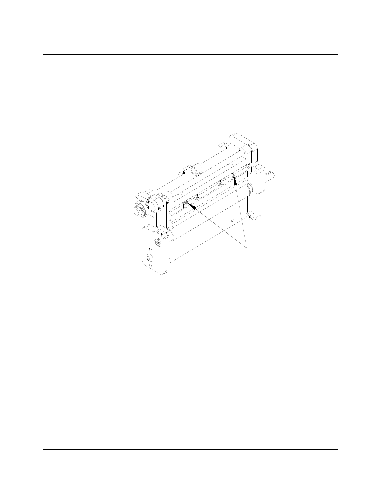
Print Head Replacement
NEVER REMOVE THE PRINT HEAD FROM THE PRINTER - EXCEPT
FOR REPLACEMENT.
TURN OFF THE POWER TO THE PRINTER BEFORE STARTING ANY
ELECTRONIC COMPONENT REPLACEMENT.
NOTE: The Anti-static wrist strap (which must contact the skin and be tight) and
anti-static gloves must be worn at all times when handling a print head to
avoid damaging the print head.
3mm SCREWS
1) The head can then be removed by loosening the two 3.0mm screws
simultaneously. The head will then drop out, sliding off the two-locator pins.
To replace, reverse the procedure - taking care that the head properly engages
the locator pins.
NOTE: The printhead connectors on the top new printhead must be upward
approximately 15 degrees to enable the printhead cable to clear the ink
roller.
2) After printhead replacement, the printer should be ready to print. There is no
tangent adjustment required. This adjustment is factory set and sealed.
Printhead pressure is also set by design and is not adjustable
NOTE: If the cable is not connected correctly, the print head will be damaged when
the printer is powered on. Check to see that the cable is tight by observing
from underneath the print head. The print head cable connector should be
inside of the black connector located on the print head.
3) Replace the ink and double-check your work. Power the printer on and make sure
that no adverse effects are noted.
4) Set the head category. Press the MODE key twice to get to the ENTER
PRINTHEAD SETUP prompt. Press the ENTER key, the press the MODE key
until the HEAD CATEGORY prompt appears. Use the <YES and NO> keys to
Users Manual Model 686 / 686 HT Adjustments / Maintenance •••• 47
Page 50
select the head category. The head category is based on the mean resistance of
the print head being used. The printhead will have a value for the average
printhead resistance, for example “Rav = 1438Ω”, printed on a label on the
printhead. Look up the value in the following table and enter the appropriate
head category. Press the ENTER key to enter the value. The printer must be
turned off and back on for the change to take effect.
HEAD
CATEGORY
AVERAGE
RESISTANCE
(Rav)
1 1075 -1123
2 1124 -1170
3 1171 -1218
4 1219 -1265
5 1266 -1312
6 1313 -1360
7 1361 -1407
8 1408 -1455
As a final test of the print head installation, run a test pattern to check the print
quality. You should observe an even grid of rectangles. If you do not see such a
grid, you may wish to reference the topic of "Print Head Tangent Adjustment".
48 •••• Adjustments / Maintenance Users Manual Model 686 / 686 HT
Page 51

Print Head Adjustment
Clean Platen Roller
You may determine if the print head has been adjusted properly by performing a test
pattern as documented under Control Buttons in this manual. A properly adjusted
print head will produce an even grid of rectangles when the test pattern is performed.
Before making any judgments as to the quality of the print head, it is absolutely
necessary to ensure that the platen roller and the printhead is clean of all
debris. Clean the platen roller located immediately beneath the print head with a
clean cloth and a small amount of alcohol. The Velcro head-cleaning pad may also
be used to clean heavy build up. Be careful not to damage the platen roller while
cleaning. If the roller is worn, replace the roller.
Print Head Tangent Point
No tangent adjust is required in the field.
Print Head Pressure Setting
No Head Pressure adjustment is available.
Squaring the Print Head
The Print Head is squared at the factory.
Stock Feed Roller Adjustment
General
The Drive module is spring-loaded and requires no field adjustment. If you have a
feed problem see trouble-shooting guide in the manual.
Knife Square Adjustment
The knife has an adjustment to square the cut to the stock. To make the adjustment,
loosen the two cap screws, one on top of the knife and one below the knife, using the
3/16” ball driver in the tool kit. Move the knife in the direction desired to square the
cut and retighten.
Users Manual Model 686 / 686 HT Adjustments / Maintenance •••• 49
Page 52

Stacker Adjustments
The stacker has four adjustments that can be made without a tool to accommodate
different types and widths of stock.
Stock Length Adjustment
Loosen the two thumbscrews at the base of the stacker uprights and slide the uprights
to a position that allows the cut tag or label to hang over the last belt roller
approximately 1/4" (6mm). Retighten.
Stock Width Adjustment
Loosen the two thumbscrews behind the stacker uprights and adjust the stacker
uprights to the desired stock width position. Retighten.
Stacker Angle Adjustment
Loosen the lever located on the side of the stacker assemble nearest the operator and
adjust the angle of the stacker with a few cut labels in the stacker so that there is a
slight gap under the last label as it hangs over the last belt drive roller. Retighten.
Stacker Full Adjustment
The sensor on the inboard stack upright is used to stop the printer when the stack is
full. A thumbscrew adjustment is provided to set the stack height.
Warning: Some stock materials cannot be stacked to the full height of the
stacker because of excessive weight.
Sensor Identification / Adjustment / Calibration
Sensor Identification:
Stock Out
A micro switch located on the back of the stock unwind will detect and stop the
printer when the stock core is lifted because the stock is consumed.
Hole / Slot Index Registration
The stock hole / slot registration is via an optical sensor used in conjunction with an
LED located in the stock funnel which allows the printer to register to pre-punched
or preprinted stock.
Reflective Index Registration
The same optical sensor that is used for stock hole / slot registration, allows the
printer to register to preprinted stock by detecting a black mark when the LED is
turned off via the format.
Ink Out
An optical sensor located near the ink unwind arbor allows the printer to monitor the
availability of ink.
50 •••• Adjustments / Maintenance Users Manual Model 686 / 686 HT
Page 53

Roller Drop (686) – Not on 686 HT
An optical sensor on back of the printer upright allows the printer to control and
register the platen roller position to perform ink save.
Feed Open
A micro switch on the back of the feed module will detect the position of the feed
module pressure knob and only allow the printer to operate with the feed pressure
knob closed.
Jam
An optical sensor located in the stacker will detect each cut label as it leaves the
cutter. If a cut fails to occur or a label remains in the sensor sight path, the machine
will stop.
Full Stacker
A micro switch on the stacker rail allows the printer to detect a full load of labels in
the stacker. The stack full condition will stop the machine when the stacker is full.
Sensor Adjustment
All the micro switches and optical sensors in your 686 / 686 HT printer were
calibrated at the time your printer was manufactured, however from time to time it
may become necessary to readjust / recalibrate due to the large variety of stocks and
inks that can be run on the machine.
Stock Out
With a full roll of stock loaded on the stock unwind with the unwind web guides
properly adjusted you should heard the switch click as you raise and lower the roll.
If not - the switch bale is adjusted by carefully bending it as needed.
Users Manual Model 686 / 686 HT Adjustments / Maintenance •••• 51
Page 54

Print Registration Sensor
Web Position Adjustment
If you are running sense mark media with a hole, slot, or preprinted mark for
registration - the registration sensor web position must be adjusted for the sense mark
media being run. The type of sensor mark registration is selected in PC Mate Plus Label Design Menu (attributes).
Hole Registration
1) Move the stock until the registration hole or slot desired is under the sensor and
over the red LED.
2) Adjust the sensor block assembly using the sensor knob while looking at the
sensor LED on the front panel. When the LED turns on with the registration
sensor over the media in the vicinity of the hole / slot, and stays on, the sensor is
over the registration hole or slot.
3) The front panel has a calibrating sensor main menu. Press the mode button until
Calibrating Sensors is showing up on the display panel then Press the enter button.
Press the mode button; the first two menu tasks will set the sensor range with the
sensor open and then blocked, (See Front Panel Menu Map in this manual).
If your machine stops, for no apparent reason, while it is in the middle of printing a
batch, you may be missing sense marks (three consecutive tickets in a row in which a
sense mark was not found). Check for the following:
Reflective Registration
- The front panel will display an error message indicating that there has been a
missed sensor.
1) Check that the web guides have been positioned properly - both on the unwind
and web guide assembly.
2) Compare the actual feed length of the sense mark stock being run with the feed
length set in PC Mate Plus.
3) Repeat the sensor alignment procedure.
1) Move the stock by opening the feed roller and print head and moving the material
until the printed mark desired is under the sensor. The LED will be turned off.
2) Adjust the sensor block assembly using the sensor knob while looking at the
sensor LED on the front panel. When the LED turns on with the registration
sensor over the media in the vicinity of the reflective mark, and stays on, the
sensor is over the reflective mark.
3) The front panel has a calibrating sensor main menu. Press the mode button until
Calibrating Sensors is showing up on the display panel then Press the enter button.
Press the mode button; the third and fourth menu tasks will set the sensor range
with the sensor open and then blocked, (See Front Panel Menu Map in this
manual).
52 •••• Adjustments / Maintenance Users Manual Model 686 / 686 HT
Page 55

Sensor Calibration
Optical Sensor Electrical Calibration
The troubleshooting section will recommend when re-calibration is required.
The following guidelines indicate the proper procedure used to calibrate these
sensors.
Note: Clean all optical sensors with clean compressed air or canned air prior to
adjustment, as dust and debris will adversely affect their performance.
Supplies
- Always use clean supplies when cleaning the sensor and LED.
- NEVER use anything abrasive on the sensor and the LED.
- NEVER use an alcohol-based solution when cleaning the sensor or LED.
- Dry air or cotton swabs are the AVERY DENNISON recommended items to use
when cleaning the sensor and LED.
There are three basic steps to calibrating each optical sensor.
1) Select the sensor to be calibrated in the Calibrate Sensors mode on the front panel.
2) Place media or ink as the case maybe in the appropriate sensor and press the
“ENTER” button on the front panel.
3) In the case of stock registration sensing - reposition the media so that a hole / slot
or black reflective mark is in the sight path of the appropriate registration sensor
and press the “enter” button on the front panel. In the case of stacker jam sensor reposition the media so the media is not in the sight path of the jam sensor and
press the “ENTER” button on the front panel.
Reflective Registration – Transfers
There is a metal plate mounted over the bottom sensor. This plate must cover the
bottom sensor.
Users Manual Model 686 / 686 HT Adjustments / Maintenance •••• 53
Page 56

Lubrication Procedure
General
The 686 / 686 HT series printers are factory equipped with either composition
bearings not requiring lubrication or pre-lubricated bronze bearings. The one
exception is the rub cams on either end of the rotary knife. Periodic cleaning of the
printer and removal of dust will greatly enhance the length of the time the printer
will function.
Cam - Lubrication Procedure
1) Clean dust and residue from cams (using alcohol or other suitable solvent) daily,
or approximately every 100K cuts. Use any good quality general-purpose grease
(not oil). Apply with cotton swab or other non-metallic device.
2) If lubrication is omitted, knife will squeak and draw attention to required
lubrication.
Composition (Iglide) Bearings
1) If field replacement of an assembly fitted with an Iglide bearing is performed, a
single drop of spindle oil should be applied to assist in bearing break-in.
2) If, after long use, an Iglide bearing starts to "squeak", disassemble the component
containing the bearing and lightly abrade the shaft surface. Clean the bearing
(dust or old oil) with alcohol, re-lubricate with 1 drop of light oil and reassemble.
Bronze Bushings
1) After extended periods of time, card dust will build up in and around the
bushings. This should be cleaned to allow free movement of the device
mounted.
2) Turn off the power to the printer.
3) Remove the device mounted in the bushing that shows signs of a cleaning
required.
4) Wipe down the part with alcohol and a cloth. The Velcro pad may be used to
clean heavy buildup.
5) Wipe out the bearing and surrounding surface with a cloth; avoid using alcohol,
as that will wipe away the natural oil impregnated into the bushing. Check for
heavy build-up and remove.
6) Add a drop of SAE 30 WT oil if available. If not - use one drop of lightweight
spindle oil.
54 •••• Adjustments / Maintenance Users Manual Model 686 / 686 HT
Page 57

Printer Set Up Sequence
1) Power off the printer, remove the stock and ink and thoroughly clean the printer
from the unwind to the stacker using alcohol and a clean soft cloth. The print
head should be cleaned as per the Print Head Cleaning section in this manual.
2) NEVER use an alcohol-based solution when cleaning the sensors or LED.
3) Load a full roll of an average width stock and ink on the printer.
4) Power on the printer. After passing the diagnostics tests the front panel will
display READY FOR BATCHES.
5) Arrow down to the Print / Cut Position mode and press enter.
6) At the Print Checkout Format screen press enter.
7) Press start. After several tags have been printed and cut, stop the printer and
evaluate the last tag out.
8) Confirm the centerline is actually in the center of the media. If it is not, first
check and adjust, as needed, the unwind core guides - then adjust the web
guides. If the print quality is inadequate, refer back to step number six.
9) Using two consecutive labels back to back, check the squareness of the cut.
Adjust the knife module as needed (refer to the Knife Square Adjustment section
in this manual).
10) Using the front panel, adjust the label leading edge cut to be 1.0" +- .032" from
the cut line printed on the label. The printer is now ready for production formats
at which time you should need only to fine-tune the print, cut, and strobe via the
front panel for individual formats.
Users Manual Model 686 / 686 HT Adjustments / Maintenance •••• 55
Page 58

Electrical Trouble Shooting
Power Up / Sign On / Communications
Problem Probable Cause Corrective Action
Printer fails to power up. 1) Incorrect AC power supplied to
printer.
2) Lack of power to printer. 1) Check that both ends of the power cord are
3) Missing or blown fuse(s) 1) Check that the fuse(s) located inside the AC
4) Cable / connector inside printer
not properly seated or
disconnected.
5) Thermal Control Board
unplugged from the Mother Board
Front panel displays no text
or nothing at all.
1) Front panel cable unplugged. 1) Power off and remove the power cord from the
1) Confirm that the AC entry is configured for the
line voltage intended to be applied to the printer.
Failure to do so can damage the printer's internal
power supply (refer to the Fuse Configuration
section in this manual).
plugged in securely.
2) Confirm that the outlet the printer is plugged
into has power.
entry are present and intact. Replace as needed
(refer to the Fuse Configuration section in this
manual).
1) Power off and remove the power cord from the
AC entry. Remove the back cover and inspect
the cables and connectors to and from the power
supplies (refer to the Electrical System
Schematic in this manual).
1) Power off and remove the power cord from the
AC entry. Remove the back cover and reseat the
Thermal Control Board.
AC entry. Remove the back cover and inspect
the cable and connectors to and from the front
panel (refer to the Electrical System Schematic
section in this manual).
56 •••• Electrical Trouble Shooting Users Manual Model 686 / 686 HT
Page 59

Front panel does not complete
Problem Probable Cause Corrective Action
1) One or more PC board(s)
diagnostics test 2.
unplugged from the Mother
Board.
Printer does not receive
batches.
1) Serial communications cable
loose or unconnected.
2) Printer not powered on or has
not completed diagnostics tests.
1) Power off and remove the power cord from the
AC entry. Remove the back cover and reseat the
offending board.
1) Check and secure both ends of the serial cable
with the thumbscrews.
1) Power printer on and wait until front panel
displays "Ready for batches". Re-download data.
3) Data sent to wrong printer. 1) In PcMate change to the printer the data is
intended to be sent.
4) Configuration incorrect in
PcMate.
1) Reconfigure PcMate for AVERY DENNISON
PCL printer as per your PcMate manual.
5) Faulty Thermal Control Board. 1) Replace Thermal Control Board.
6) Jumpers not configured
1) Contact AVERY DENNISON Service.
correctly.
Users Manual Model 686 / 686 HT Electrical Trouble Shooting •••• 57
Page 60

Stock / Ink Advance
Problem Probable Cause Corrective Action
Stock does not advance
when the start button is
depressed.
2) An interlock condition exists. 1) Determine the number and type of interlock(s)
3) Feed motor unplugged or faulty. 1) Check feed motor cable and or replace feed
4) Thermal Control Board
5) Feed roller not closed. 1) Close feed rollers and press start twice (once to
6) Feed rollers bound. 1) With power off check that all rollers turn freely.
7) Stock bound. 1) With the print head and feed open check that the
Ink does not advance when
the start button is
depressed.
1) No batches to be printed. 1) Download batch (if batch downloaded uses the
same format as a previously downloaded batch the printer with start automatically).
by reading the front panel display. As each is
corrected the number of errors will decrease
(Example "Error 901 Stock Out" reload stock).
motor.
1) Check Thermal Control Board / AT board
unplugged or faulty.
1) No batches to be printed. 1) Download batch (if batch downloaded uses the
connection and or replace Thermal Control
Board.
clear the feed open error, and once to start
printer).
stock will pull through the printer with little
resistance.
same format as a previously downloaded batch
the printer with start automatically).
2) An interlock condition exists. 1) Determine the number and type of interlock(s)
by reading the front panel display. As each is
corrected the number of errors will decrease
(Example "Error 901 Stock Out" reload stock).
3) Ink motor unplugged or faulty. 1) Check ink motor cable and or replace ink motor.
4) Thermal Control Board
unplugged or faulty.
5) Ink roller bound. 1) With power off check that all rollers and arbors
6) Ink bound. 1) With the print head open - check that the ink
58 •••• Electrical Trouble Shooting Users Manual Model 686 / 686 HT
1) Check Thermal Control Board / AT board
connection and or replace Thermal Control
Board.
turn freely.
will pull through the printer with little to no
resistance.
Page 61

Print
Problem Probable Cause Corrective Action
Printer advances stock but
does not print.
2) Print head cable unconnected or
3) Print head faulty. 1) Replace print head.
4) Head Driver Board unplugged or
Printer stops after ever
third label.
2) Stock registration sensor
Print registration is off in
the feed direction.
2) Field(s) position incorrect in the
3) Bound platen roller. 1) Check that the platen roller turns freely on its
1) Stock registration sensor miss
aligned.
faulty.
faulty.
1) Stock registration sensor miss
aligned.
uncalibrated.
1) Printer print position is incorrect. 1) Enter the Print / Cut Positions Mode on the
format.
1) Adjust sensor position so that the sensor light
on the front panel flashes as a sense mark hole
passes under the sensor.
1) Power off the printer and reinsert the offending
connector or replace cable.
1) Check Head Driver Board / AT board
connection and or replace Head Driver Board.
1) Adjust sensor position so that the sensor light
on the front panel flashes as a sense mark hole
passes under the sensor.
1) Calibrate the sensor (refer to the Sensor
Calibration section in this manual).
front panel and readjust the Print Position
setting as needed.
1) Using PcMate Platinum – check and readjust
the field(s) position(s) as needed.
shaft. If it does not, clean bearing or replace it.
Print registration is off in
the web direction.
2) Web guides incorrectly adjusted. 1) Check and adjust as needed (refer to Web Guide
3) Unwind incorrectly adjusted. 1) Check and adjust as needed (refer to Web Guide
4) Incorrect DIP switch settings on
1) Printer incorrectly threaded. 1) Check and rethread the stock as needed (refer to
Loading Stock section in this manual).
Adjustment in this manual).
Adjustment in this manual).
1) Check and reset DIP switches as needed (refer
the Thermal Control Board.
to TCB Dip Switch Settings section in this
manual.
Users Manual Model 686 / 686 HT Electrical Trouble Shooting •••• 59
Page 62

Problem Probable Cause Corrective Action
Print contrast is too light or
dark.
1) Incorrect strobe setting selected
in the format.
1) Using PcMate Platinum - check and adjust the
strobe setting according to the stock and ink
being used.
2) Printer strobe setting is incorrect. 1) Enter the Print Head Setup Mode on the front
panel and readjust the Strobe setting as needed.
Voids in print image in the
feed direction.
1) Ink miss aligned with format. 1) Adjust ink position on the arbors to achieve full
ink coverage over all fields on the format.
2) Print head dirty. 1) Power off the printer - clean the print head and
platen (refer to Print Head Cleaning section in
this manual).
3) Faulty print head. 1) After cleaning head and running the test pattern
to confirm that a void still exists, replace the
print head.
4) Worn platen roller. 1) Replace platen roller.
Printer continually stops
with an erroneous
interlock condition.
1) Sensor uncalibrated. 1) Determine which sensor and re-calibrate as
needed (refer to Sensor Calibration section in
this manual).
2) Sensor position miss-adjusted. 1) Determine which sensor and relocate
accordingly.
60 •••• Electrical Trouble Shooting Users Manual Model 686 / 686 HT
Page 63

Cut / Stack
Problem Probable Cause Corrective Action
Printer fails to cut labels
(the rotary knife does
not rotate).
2) Knife cable unconnected. 1) Power off and remove the power cord from the
3) Knife jammed causing auto
4) Faulty knife motor. 1) Replace the knife motor.
5) Faulty knife motor drive circuit
The stacker fails to run. 1) The stacker cable is unconnected. 1) Power off and insert the stacker cable in the
2) Faulty stacker motor. 1) Replace the stacker motor.
3) Stacker jammed causing auto
4) Faulty stacker motor drive circuit
1) The cut is disabled in the Feature
Setup mode.
resetting fuse to trip on the
Thermal Control Board.
on the Thermal Control Board.
resetting fuse to trip on the
Thermal Control Board.
on the Thermal Control Board.
1) Enter the Feature Setup Mode on the front panel
and Enable the knife.
AC entry. Remove the back cover and inspect
the cable and connector to the knife module
(refer to the Electrical System Schematic
section in this manual).
1) Remove cause of jam at the knife.
1) Replace the Thermal Control Board.
stacker socket on the Thermal Control Board.
1) Remove cause of jam at the stacker.
1) Replace the Thermal Control Board.
Users Manual Model 686 / 686 HT Electrical Trouble Shooting •••• 61
Page 64

Mechanical Trouble Shooting
Stock
Problem Probable Cause Corrective Action
Stock will not roll or jumps 1) Incorrect adjustment of unwind
web guides
2) Adjust unwind knob until back plate and front
3) Adjust the web guide to the edge of stock. Do
Printer fails to stop at end
of roll.
Stock does not pull
smoothly through
printhead module.
2) Stock is slipping in drive or drive
1) Stock roll is too tight in guides. 1) Adjust unwind knob until back plate and front
1) Web guide is too tight. 1) Adjust turn-bar collars to same position as
pressure is uneven.
1) Be sure stock roll is as flat as possible and does
not extend over core.
post touch roll. Do not over-tighten. Roll must
rotate smoothly.
not pinch web.
post touch roll. Do not over-tighten. Roll must
rotate smoothly.
unwind back plate and front post.
1) Be sure cam lift knob is closed. Be sure springs
are not improperly installed on bottom pins. Be
sure cam lift surfaces are not holding lift arms
up when knob is in the run position. Re-adjust
unwind and web guide to relieve possible stock
“pinch”.
62 •••• Mechanical Trouble Shooting Users Manual Model 686 / 686 HT
Page 65

Problem Probable Cause Corrective Action
Cracks or craze marks
appear on face of
1) Incorrect adjustment of decurler. 1) Move decurler turn-bar toward unwind end of
printer until cracks no longer appear.
finished labels.
Stock jams in bridge blade
rollers or knife area.
2) Stacker not operating or nip
1) Knife not cutting full width of
stock.
rollers not turning.
1) Loosen knife shear adjustment screws and move
outer end of knife until full cut is accomplished.
1) Check stacker connection to access port. Be
sure nip roller is free to rotate and moves easily
in the bearing slots.
Will not stack. 1) Stacker not operating. 1) Check stacker connection to access port. Be
sure nip roller is free to rotate and moves easily
in the bearing slots.
2) Stacker position on printer too far
forward so labels go under stacker
rail.
3) Incorrect rail position or stacker
bed angle.
1) Loosen stacker mounting knob and move
stacker toward rear of printer - tighten.
2) Adjust position of stacker rails.
1) Using a cut label, position stacker rails so that
approximately 3/8" (9.5mm) overhangs the
second grooved roller. Loosen quick-turn
handle on stacker clamp and raise or lower
stacker bed until opening between 1st label
overhang and belt surface will allow entry of
next label.
Knife will not cut or partial
cut
1) Incorrect pre-load on clutch pawl. 1) With back cover removed and power off operate solenoid by hand. When lever is moved,
clutch pawl should move counter-clockwise
about 1/32" (0.79mm) with the "pac-man" in
home position. If not - loosen "pac-man" set
screws and readjust "pac-man" to stop with
spring in detent.
2) Partial cut 1) Loosen shear adjustment screws and move outer
end of knife until full cut is obtained.
Users Manual Model 686 / 686 HT Mechanical Trouble Shooting •••• 63
Page 66

Ink
Problem Probable Cause Corrective Action
Ink wrinkles or will not
pull smoothly.
2) Ink buildup on turn bar(s). 1) Clean with alcohol.
3) Incorrect ink width. 1) Use ink 1/4 inch wider than stock being printed
Ink rolls loosely on take-up
roller.
2) Take-up core binding on locator
3) Take-up roller too full. 1) Remove used ink roll. It is designed to hold
1) Unwind roller and ink take-up
roller misaligned.
1) Take-up roller not turning. 1) Be sure belt is on rear drive sprocket. Be sure
plate.
1) Align rear edge of ink with rear of print area
(allow approximately 1/8" (3mm) overlap).
Loosen thumb cap screw on ink roll locator
plate and adjust until it touches rear of ink roll
on unwind arbor. Slide rewind cores toward
rear of printer until it just contacts plate.
by overhanging 1/8 inch on either side of stock.
This is especially critical when using a narrow
web with cut down rollers.
magnetic drive (rear of center frame) can turn
freely. No adjustment for tension is available
or required.
1) Move core .015" - .030" (.38mm - .76mm) away
from plate.
only 1 full roll.
Print
Problem Probable Cause Corrective Action
Poor print - uneven or no
print (mechanical).
Also see electrical
troubleshooting.
64 •••• Mechanical Trouble Shooting Users Manual Model 686 / 686 HT
1) Broken ink. 1) Replace ink and readjust (see INK
troubleshooting).
Page 67

Users Manual Model 686 / 686 HT Electrical Drawings •••• 65
Electrical Drawings
Page 68
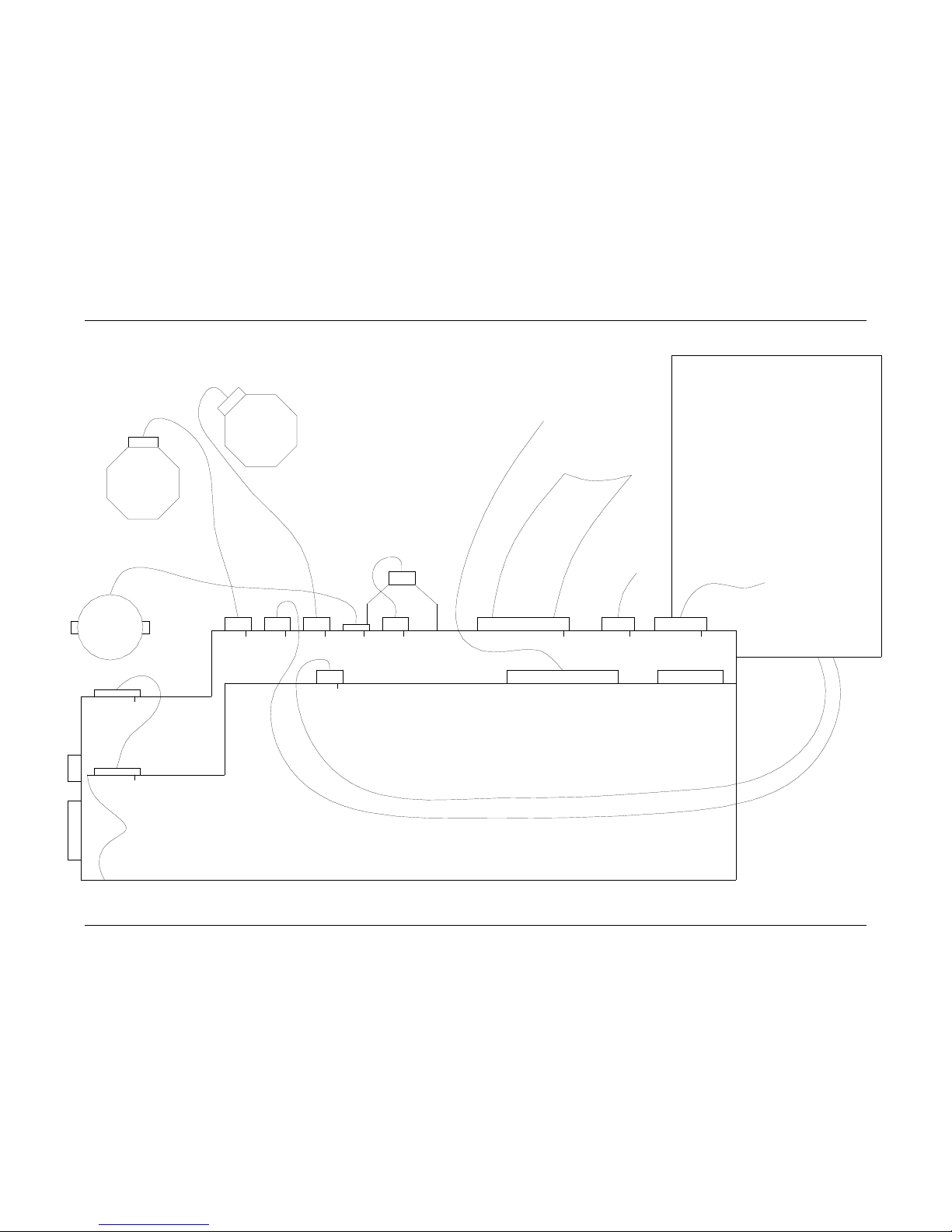
66 •••• Electrical Drawings Users Manual Model 686 / 686 HT
Printer Wiring
THERMAL CONTROL
BOARD, 371105NE
HEAD DRIVER
BOARD,
341106NE
ROLLER
DROP
MOTOR
KNIFE
MOTOR
STACKER
J9
SERIAL
J6
GRAY
J7
BROWN
J3
BROWN
J2
ORANGE
J8
GRAY
J7
ORANGE
J10
RED
J12
ORANGE
J11
FEED
MOTOR
INK
MOTOR
FRONT PANEL
BROWN
J2
OPEN
J13
BROWN
J1
NC
J1
BROWN
J5
VERIFIER
SYSTEM HARNESS
PRINT HEAD
24V
POWER
SUPPLY
511116
Page 69
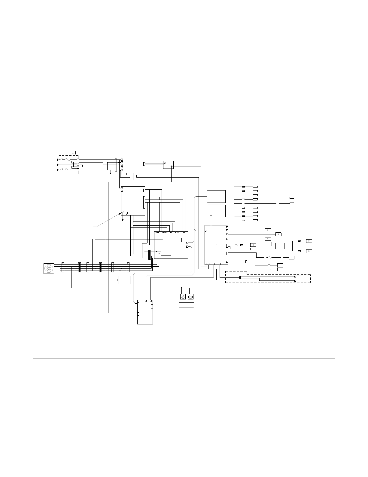
Users Manual Model 686 / 686 HT Electrical Drawings •••• 67
Electrical System Schematic
NOTES:
1. ALL AC WIRE 18AWG 600V INTERNATIONAL
COLOR CODE:
LINE BROWN
NEUTRAL LT. BLUE
EARTH GROUND GREEN W/ YELLOW STRIPE
2. DC OUTPUT OF POWER SUPPLY:
+5V RED
+12V YELLOW
+24V GRAY
RETURN BLACK
3. FLASH DISK REPLACED PCMCIA BOARD, REMOVE IF FLASH
DISK IS INSTALLED.
ONE OF FOUR
MOUNT STAND-OFFS / NUTS
DO NOT POWER ON WITHOUT
SUFFICIANTLY SECURED
GROUND
551147 MOTOR 551146A
MODULE, FLASH DISK
16MB MEMORY 341146A
IDE 2 (J6)
341106NE
DRIVER
HEAD
BOARD
J7
J4/J5
J4
J1 N.C.
PRINT HEAD CABLE
J3
J2
551123
MACHINE COOLING
FAN 511120
NC
NC
10
BASE T
OPTIONAL
CONVERTER
TO SERIAL
ETHERNET
550028
FAN HARNESS 551130
PRINT HEAD COOLING
CONN 4CONN 4 CONN 4 CONN 4CONN 4
PROCESSOR
CONN 4
551149
FAN
CONN 4
341147
371190
MOTHER BOARD
PRINTHEAD
551102 - 300 DPI
HARNESSED 351161
STACKER MOTOR
551144
SCANNER
JAM SENSOR
CONN 9
551131 (2X)
PRINT HEAD
COOLING FAN
TCB TO HDB
351121
HARNESS
551114
VERIFIER
INTERNAL
OPTIONAL IN LINE VERIFIER 550021
CONN 3
HARNESS 551115
VERIFIER
HARNESSED 371133
351132
(FUSE 990755)
SERIAL CABLE
EXTERNAL 351124
KNIFE FUSE HARNESS 359007
STACKER HARNESS
371105NEIS
J7
J6
J5J2
J9
351125
THRMAL CONTROL
BUS
VL
BUS
AT
J12
BOARD
J10
SOLDER SIDE
CONN 9
ORANGE
(FUSE 990915)
HARNESS 359006
STACKER FUSE
CONN 3
HARNESSED 351160
FULL STKR SWITCH
CONN 2
INK MOTOR
245026
KNIFE MOTOR
HARNESSED 551171
HARNESSED 351123
KNIFE SOLENOID
551140
IADB
551141
J2J1
551105
CONN 4
CONN 4
RED
ARBOR
MOTOR
MOTOR
INK REWIND
221113
INK SUPPLY
ARBOR
221113
10
G
NEUTRAL D
+5V
341115
31 2 8 96 754
RETURN
230V OPERATION
TWO 10.0A 250V
5 X 20MM FUSES 921168
115V OPERATION
1/4 X 1 1/4 FUSE 921167
ONE 10.0A 250V
341118
5V / 12V
POER SUPPLY
N
L
+12V
RETURN
LINE
GROUND
LINE CORD
181134
CONN 6
B
C
A
AC ENTRY
341111
230V
115V
POWER SUPPLY
N
115V STRAP
115V STRAP
+24V
511116
L
990998
DIODE
HARNESSED 24V
REGISTRATION GAIN
SWITCH 551170
IR LED 551169
CONN 2
CONN 3
CONN 4
CONN 4
351132
ASSEMBLY 551126
SYSTEM HARNESS
STEPPER MOTOR CABLE
TCB TO FP
11 12
J3/J4
J13
J1
J11
J8
CABLE
351119
FRONT PANEL ASSY
OVERLAY 511111
CODE 800265
J1
PCB 511110
511108
TOP CONTRAST SENSOR
245026
FEED MOTOR
510014 SICK OR 510012 OMRON OPTIONS
ROLLER DROP
TOP REGISTRATION
BOTTOM REGISTRATION OPTION
ROLLER DROP
SENSOR 371130
SENSOR 371128
SENSOR 371128
CONN 2
CONN 2
CONN 4
CONN 2
PCMCIA
351181
BOARD
OPTIONAL
SEE NOTE 3
HARNESSED 371142 SWITCH 191120
HEAD OPEN
INK OUT
GROUND CONTACT
SENSOR 371118
SWITCH 551122
FEED CONTROL
CONN 3
STOCKOUT SWITCH
Page 70
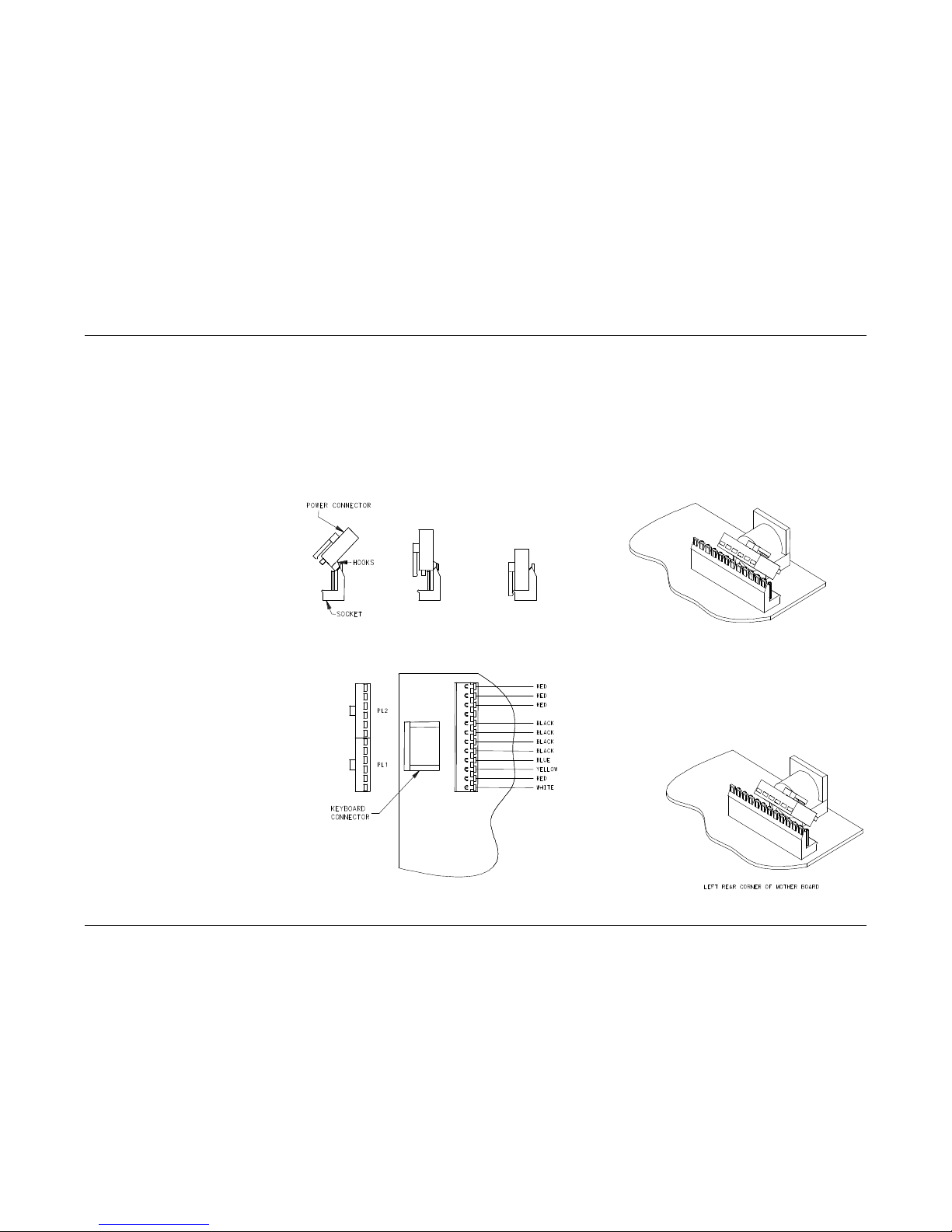
68 •••• Electrical Drawings Users Manual Model 686 / 686 HT
Motherboard Power Connectors
The power supply connector on any PC/XT or PC/AT compatible motherboard is made up of dual six-pin male connectors.
Two female connectors from the power supply plug directly onto these male connectors. The following diagrams illustrate
the proper method of attaching the connectors.
Ensure that all of the black wires are located next to each other in the center of the two connectors (as shown in the diagram
below), and that the clamps on the backside of the connectors ate secured along the PCB header. All pins should be covered.
Warning: Connecting the power supply incorrectly may cause irreversible (unwarranted) damage! Ensure that the power is
turned off before connecting the power supply. Make certain that the 115 / 230VAC fuse drawer is in the correct
position.
Page 71
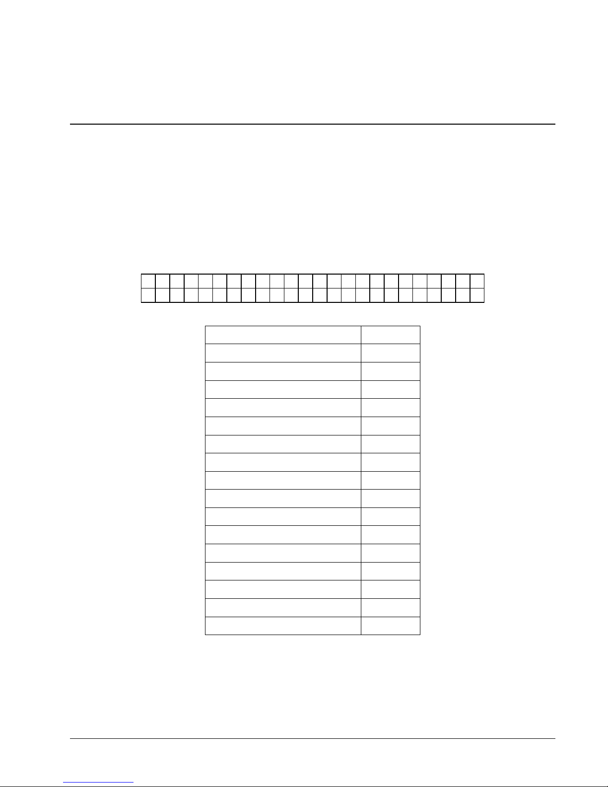
Appendix A
Error Messages
On the Machine's detection of errors / error, the displays will show the first error encountered and allow the
displaying of any other errors with the <YES / NO> keys, which will "Scroll" through additional errors if any.
XX is the total number of errors at the time of error detection.
ERROR SCREENS:
The screen advances to next error with each depression of the "NO>" key
The screen retreats to prior error with each depression of the "<YES" key
The screen reverts back to the first error when the “EXIT” key is pressed.
X X E R R O R ( S )
S T O C K O U T 9 0 1
Error Message Error
HEAD 1 OVER TEMP 404
HEAD 2 OVER TEMP 405
HEAD 3 OVER TEMP 406
STOCK OUT 901
CHECK STACKER 902
INK OUT STATION 1 904
INK OUT STATION 2 905
INK OUT STATION 3 906
MISSED SENSE MARK 908
FEED OPEN 910
VERIFIER HALT 1 912
VERIFIER HALT 2 913
IMAGER ERROR 919
HEAD OPEN STATION 1 920
HEAD OPEN STATION 2 921
HEAD OPEN STATION 3 922
Users Manual Model 686 / 686 HT Appendix A •••• 69
Page 72
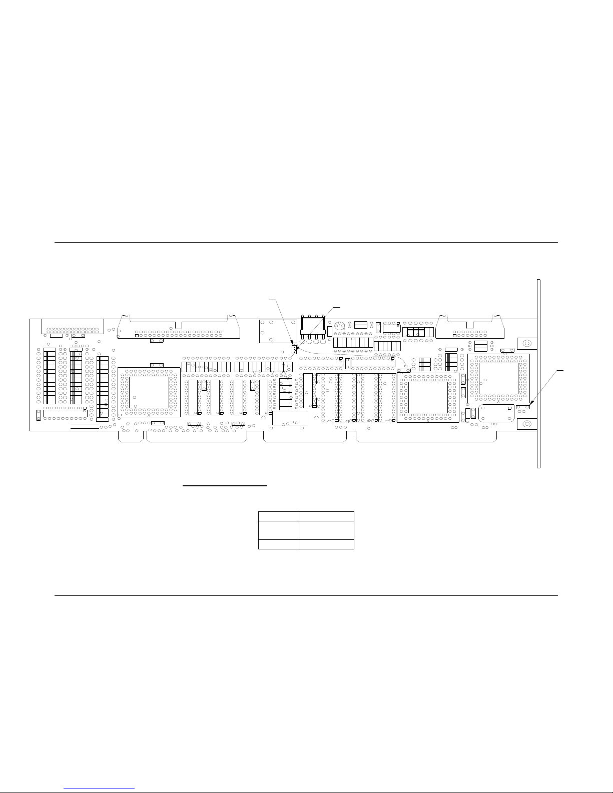
70 •••• Appendix B Users Manual Model 686 / 686 HT
Appendix B
Software Upgrade Chip Placement Positions
Head Driver Board P/N 341106NE
PN .3 41 10 6 RE V 0
PA X AR S N .
U17
D8
D10
D39
D27 D20
D2
D26 D14
D1
R5
A58
D7
D19
D4
D38 D16
D13
D41
D29
D37
D3
D25
D15
U2
C9
C7
R56
R55
R54
R42
R41
C6
U11
R53
R52
R51
R50
R49
U13
C5
C2
C8
C4
J6
1
J1
16
D47 D23
D11D35
D22
A45
A1
C1
D9
D46
D34
D21
D44
D32
R4
R14
15
30
R2
D48
D45
D36
D33
D24
D12
U14
JP1
C21
J3
C22
U16
R57
R60 R59
D6 D43
C20
C19
C18
R64
C17
R62
R61
D31
D18
D30
R63
D40
D28
D17
D5D42
J4
U9
R3
R22
U4
R13R 12
C16
U1
R24
R9
R21R 19
R10
C3
R11
U8U7
R23
Q1
R8R6
R18R16 R1 5
C14
C10
U6
C11
A1
R7
R17
R1
U3
C13C12
U5
J7
4321
U15
J5
R38
R39
R37
R36
R20
R32
R40R31
R30
R29
R28
R27
R26
R25
K1
R33
R47
R46
R35
R34
C23
+
U10
C15
J2
R48
R45
R44
R43
U12
U 1 7
U 1
U 1 4
J P 2
JP 1
P IN 1
HEAD DRIVER BOARD, Upgradeable software I.C.'s include U1, U14, U17.
PLCC CHIPS align angled corner of chip with angled corner of socket that is counter clockwise to the arrow.
(Use chip removal tool P/N. 351156 for square I.C removal)
JUMPER SETTING
JP1 On = 240DPI
Off = 300 DPI
JP2 1 to 2
Page 73
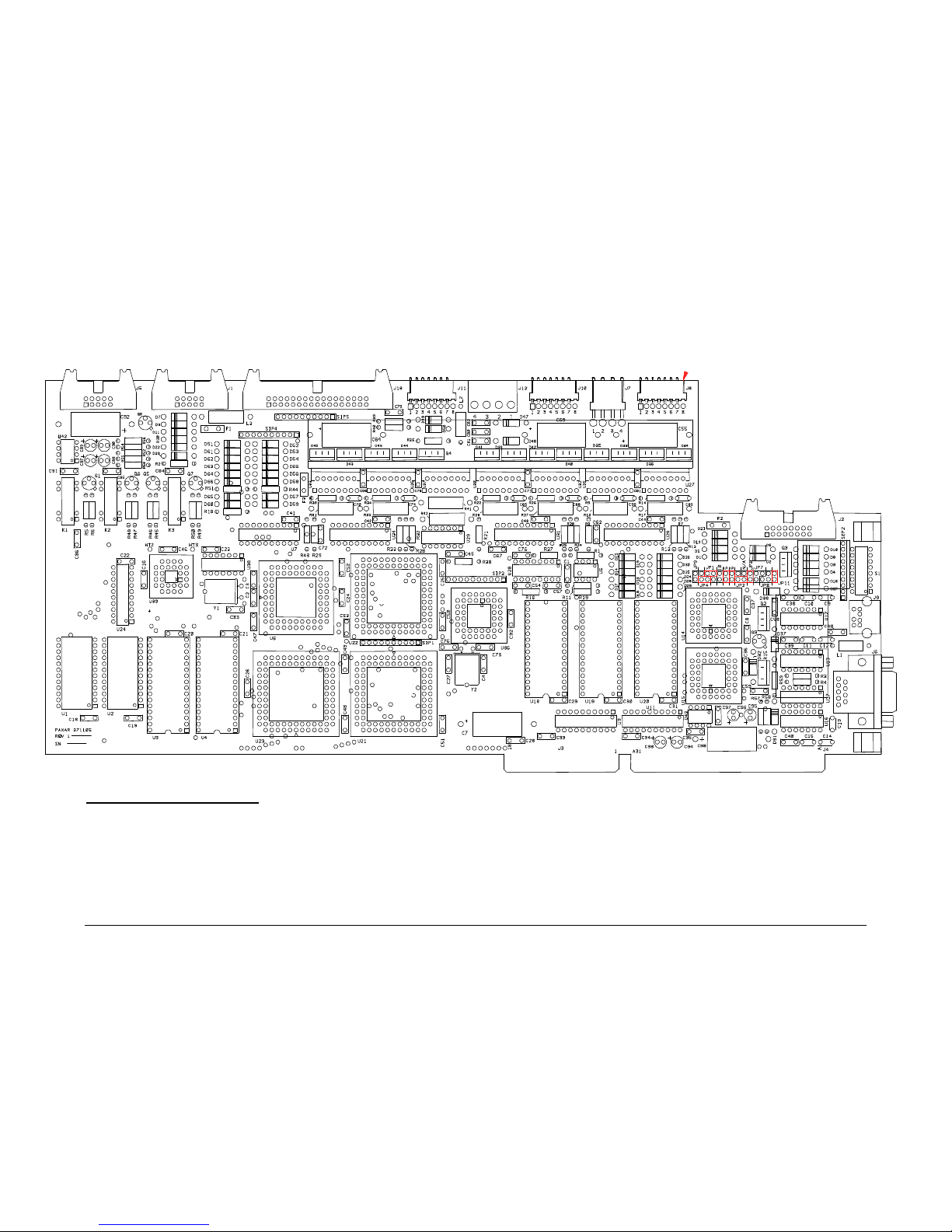
Users Manual Model 686 / 686 HT Appendix B •••• 71
Thermal Control Board P/N 371105NE
U 36
U 23
U 21
U 4
U 3
U 18
U 19
U 20
U 22
THERMAL CONTROL BOARD, Upgradeable software I.C.'s include U3, U4, U18 - U23, U36.
PLCC CHIPS align angled corner of chip with angled corner of socket that is counter clockwise to the arrow.
DIP CHIPS align notch on chip with the notch on the socket (U3 & U4 chips are four pins smaller than U3 & U4 sockets, position chips towards top of socket so
that the unused socket pins are at the bottom closest to the notch.
(Use chip removal tool p/n. 351156 for square I.C.'s)
Page 74
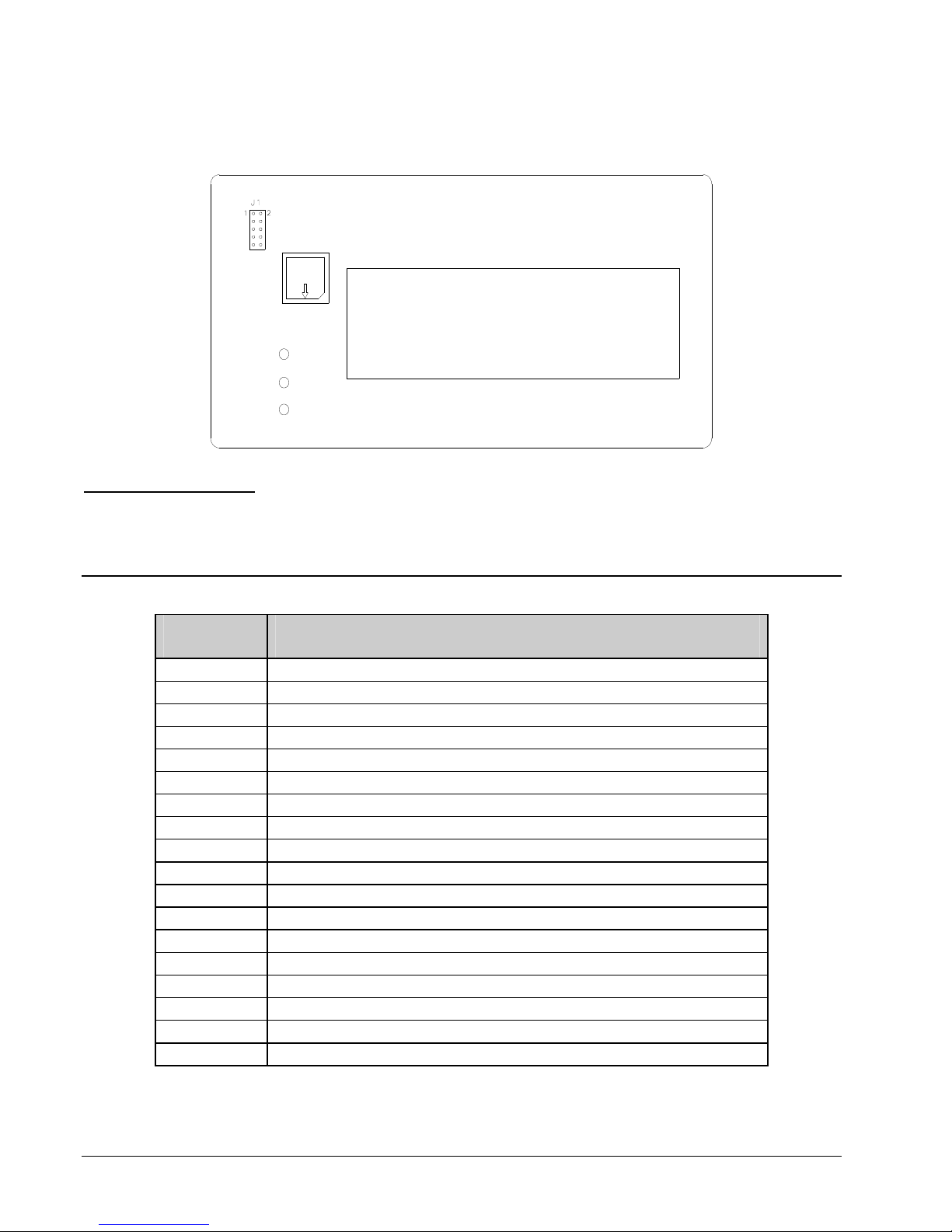
Front Panel Board P/N 511108
FRONT PANEL BOARD, Upgradeable software I.C.'s include U1.
PLCC CHIPS align angled corner of chip with angled corner of socket that is counter clockwise to the arrow.
(Use chip removal tool p/n. 351156 for square I.C.'s)
Front Panel Diagnostic Descriptions
Diagnostic
Numbers
Descriptions
1 Front panel initialization
2 TCB Opsys initialization
5 Attempting Serial Host Initialization
6 Initializing Verifier
7 Executing Protected Mode Imaging Code
8 Checking Flash Disk Module
9 Attempting to read in scalable fonts.
10 Initializing Font Scaler
11 Attempting to load code pages
12 Attempting to read in logos
13 Attempting to read in care symbols
14 Waiting for Machine Definition from TCB
15 Attempting to create test pattern
16 Attempting to create strobe tables
17 Attempting to read in formats
18 Protected Mode Imaging Code initialization complete
19 Serial Communications Activated
0 Power up complete
72 •••• Appendix B Users Manual Model 686 / 686 HT
Page 75
Appendix C
Ink and Stock Transfer Types
Transfer Type values associated with the XT commands.
Value Transfer Type
201 Coated Tag Stock & GN1111
202 Tag Stock A & GN1111
203 Tag Stock B & GN1111
204 Tag Stock C & GN1111
205 Tag Stock D & GN1111
Users Manual Model 686 / 686 HT Appendix C •••• 73
Page 76
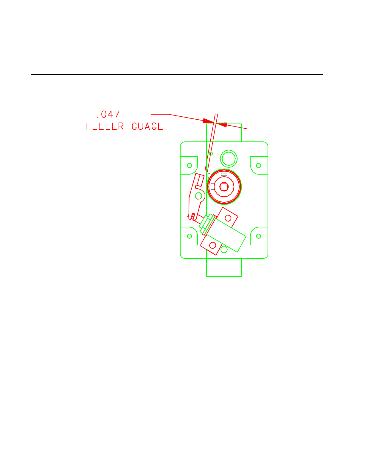
+.000
Appendix D
Knife MFG Guideline
Solenoid Trigger Setting
-.020
1. After the clutch and actuator is mounted to the knife, attach the solenoid assembly to the inside
support using two 6-32 x 3/8 cap screws, flat washers, and lock washers. Make sure the plunger
moves freely and does not bind. Motor and faceplate must be mounted also.
2. Check the gap between the actuator and the top of the pin on the clutch as shown in drawing.
The plunger should be pushed in to make the measurement.
Other hints if there is still a problem:
• If the gap is greater then .047”, an old solenoid bracket is being used. Replace (P/N 357003) or
slot the bracket.
• If plunger binds, the solenoid is not parallel with the base of the bracket that mounts to the knife
support, and / or the actuator slot is bottoming out on the roll pins that are on the plunger. Make
adjustment or replace the bracket.
74 •••• Appendix D Users Manual Model 686 / 686 HT
Page 77
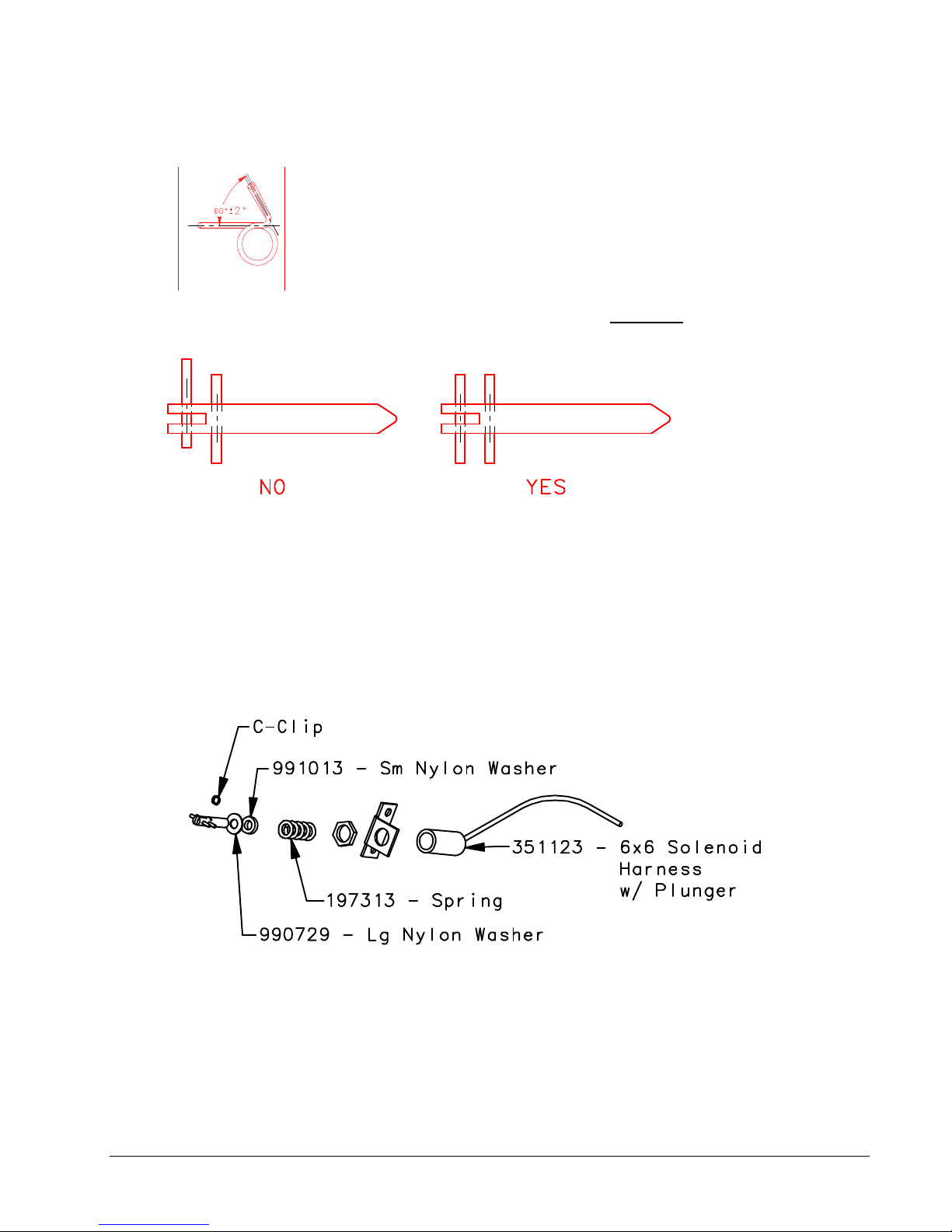
• Torsion Spring should be at an angle of 60±2°. Lay the spring over the drawing below to see if
the spring is made properly.
• Plunger pins should be centered on shaft. If either pin is loose DO NOT use the plunger. The
pins should be checked before installing.
• (Rev 3) Replace both roll pins on all reworked assemblies.
• (Rev 4) Effective 3/3/97 a large nylon washer will be added between the coil pin and the c-clip
on the plunger. To install, the c-clip has to be removed, then put the large washer on the
plunger and push it down against the coil pin. While holding it in that location, re-install the cclip. Now the Small nylon washer and spring can be put on the plunger and inserted into the
solenoid.
- 989513
Users Manual Model 686 / 686 HT Appendix D •••• 75
Page 78
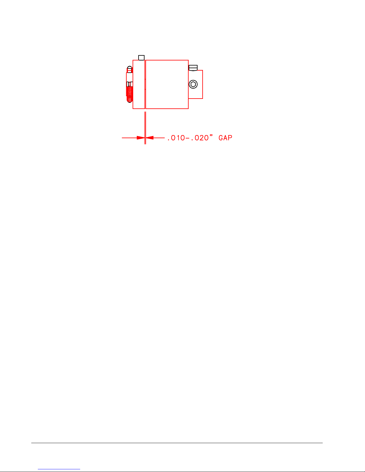
• There should be a .010-.020 gap (for roller clutch only) between the two clutch pieces.
• (Test on the solenoid test box.) The knife must cut both fabric and card stock. The solenoid
should operate on both the high and low settings.
• Excessive motor drag must be minimal at start / stop and while running. Replace or repair
problem component. On old knife assemblies, there are bronze bushings in outer support. They
may be causing a bind. Ream bushing and retest. (Do not ream if it is a roller bearing.)
• (Rev 1) Pre-load setting adjustment. While motor is running, not while cutting, loosen set
screws on “Pac-man” and rotate the rotary blade clockwise, mark the stopping position on the
“Pac-man”, rotate counterclockwise, mark the “Pac-man”, then rotate the blade to the middle of
the two marks and tighten the set screws.
• (Rev 2) All new knife assemblies have a blue clutch. The clutch outer race bushing has an I.D.
of .500 and the 2 extension springs are .012-dia wire.
• (Rev 2) The 2 extension springs on all rebuilt clutches must have the .009 Dia. wire springs
replaced with .012 wire springs.
• (Rev 5) Replace Knife Actuator 357020, if it is worn or if there is a “bulge” at the 90-degree
bend.
• (Rev 6) Changed feeler gauge tolerance from .047 MIN
76 •••• Appendix D Users Manual Model 686 / 686 HT
Page 79
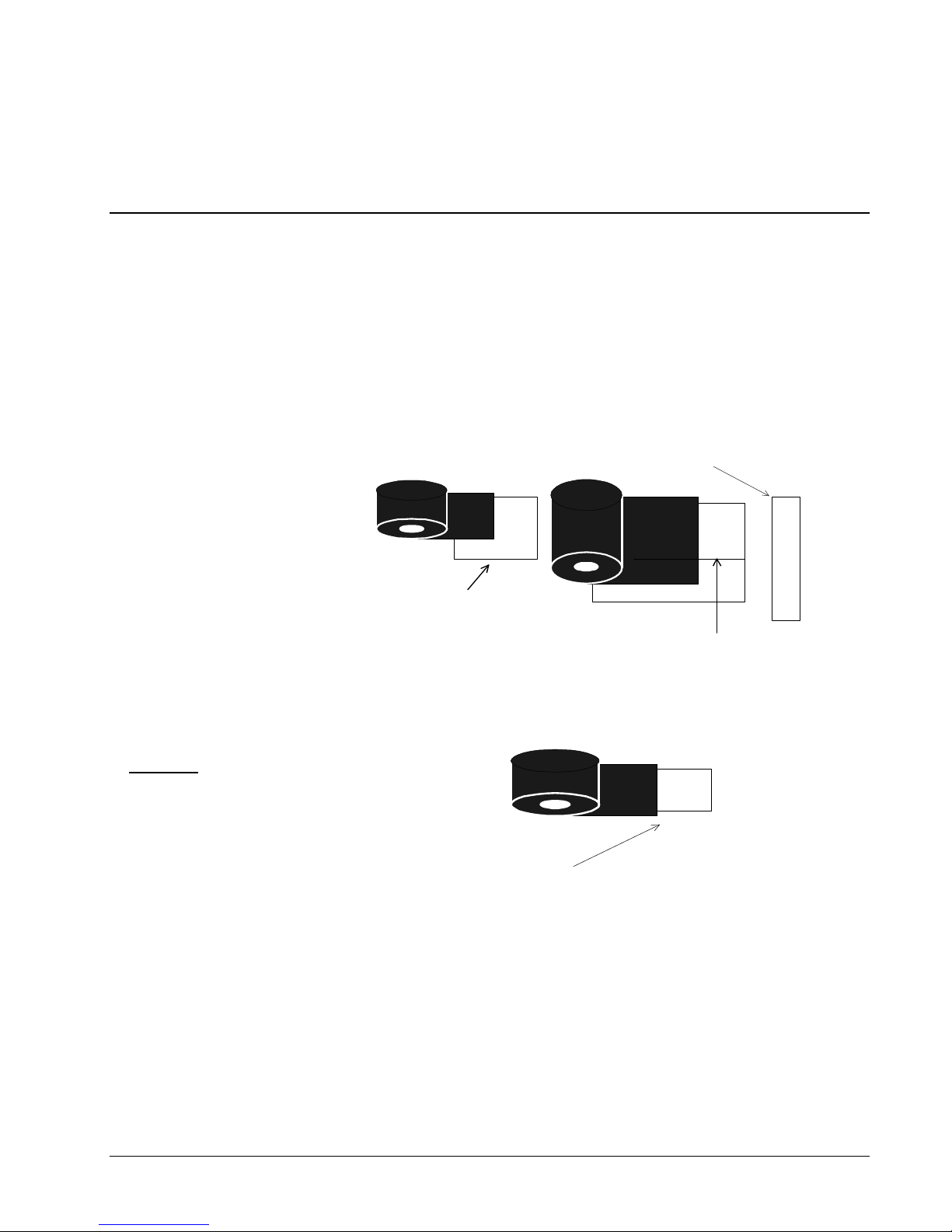
Appendix E
Printhead Life Extension
Matching stock and ink widths
If you’re running multiple media and multiple widths on your AVERY DENNISON machine, Great! You are
taking advantage of one the most compelling features of our printers: multimedia capability. Our printers can
also reduce the width of the ink to only that area being printed. However, we run into printhead problems
when customers combine both these features.
The edge of the narrower stock not covered by the ink will gouge the printhead and cause dots to be
out.
Here, the customer will have
much shorter printhead life
because of the edge of the
narrower, uncovered stock.
Printhead
WRONG!
The solution is to make sure
that the narrower stocks have
at least 1/8” of ink coverage
over the edge.
RIGHT!
This edge which is
not covered by ink
will erode the
printhead.
Will have missing dots from
the eroded printhead when
this prints out.
Must have 1/8" inch
overlap to protect the
printhead from the
stock edges
Users Manual Model 686 / 686 HT Appendix E •••• 77
Page 80
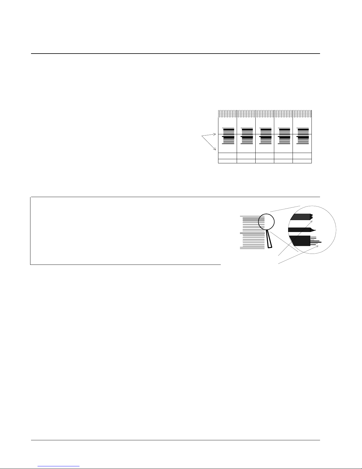
Printhead Fail Modes
Symptoms, Causes, Solutions
Symptom #1:
sometimes in the print area, and sometimes not. If in a barcode, the verifier will halt the printer.
Cause: Paper dust or dirt on the printhead causing
the ink to print without printhead firing. The dot is
NOT failed on. The printhead is DIRTY.
If not addressed immediately: the line will go
from black or gray to white and the dot will fail. The
printhead will be damaged.
Solution: Immediately stop the printer and clean the printhead in the machine.
If problem continues: Remove the printhead and clean with hard pressure.
A dot is leaving a line in the print direction. The dot appears to be dragging or failed on,
Lines of
print from
a dragging
dot
Specialty
Style: Fall
Color: Rose
23456 78901
Brand
$5.95
Specialty
Brand
Style: Fall
Color: Rose
23456 78901
$5.95
Specialty
Brand
Style: Fall
Color: Rose
23456 78901
$5.95
Color: Rose
23456 78901
Specialty
Brand
Style: Fall
$5.95
Specialty
Brand
Style: Fall
Color: Rose
23456 78901
$5.95
Symptom #2:
Edges of barcode and text do not appear crisp
and sharp.
Cause: Strobe is too high. Printhead is dirty.
Solution: Reduce front panel strobe one increment at a time until fuzzy
printing goes away.
If problem continues: Clean the printhead as described below.
Symptom #3:
appears missing. The verifier will halt the machine if the missing dot is in a barcode.
While printing along fine early in the printheads life (< 300,000 inches), a dot suddenly
Cause: Most likely, the printhead failed from static.
Solution: Replace the printhead.
If problem continues: Check that the machine has all the static upgrades. Double-check the
connections and wires. Check that the AC outlet supplying the printer has a true ground
path. AVERY DENNISON printers remove static through the frame and out the ground leg
on the AC power cord. If this path does not exist, it will build up in the printer.
23456 78901
Fuzzy edges
78 •••• Appendix E Users Manual Model 686 / 686 HT
Page 81
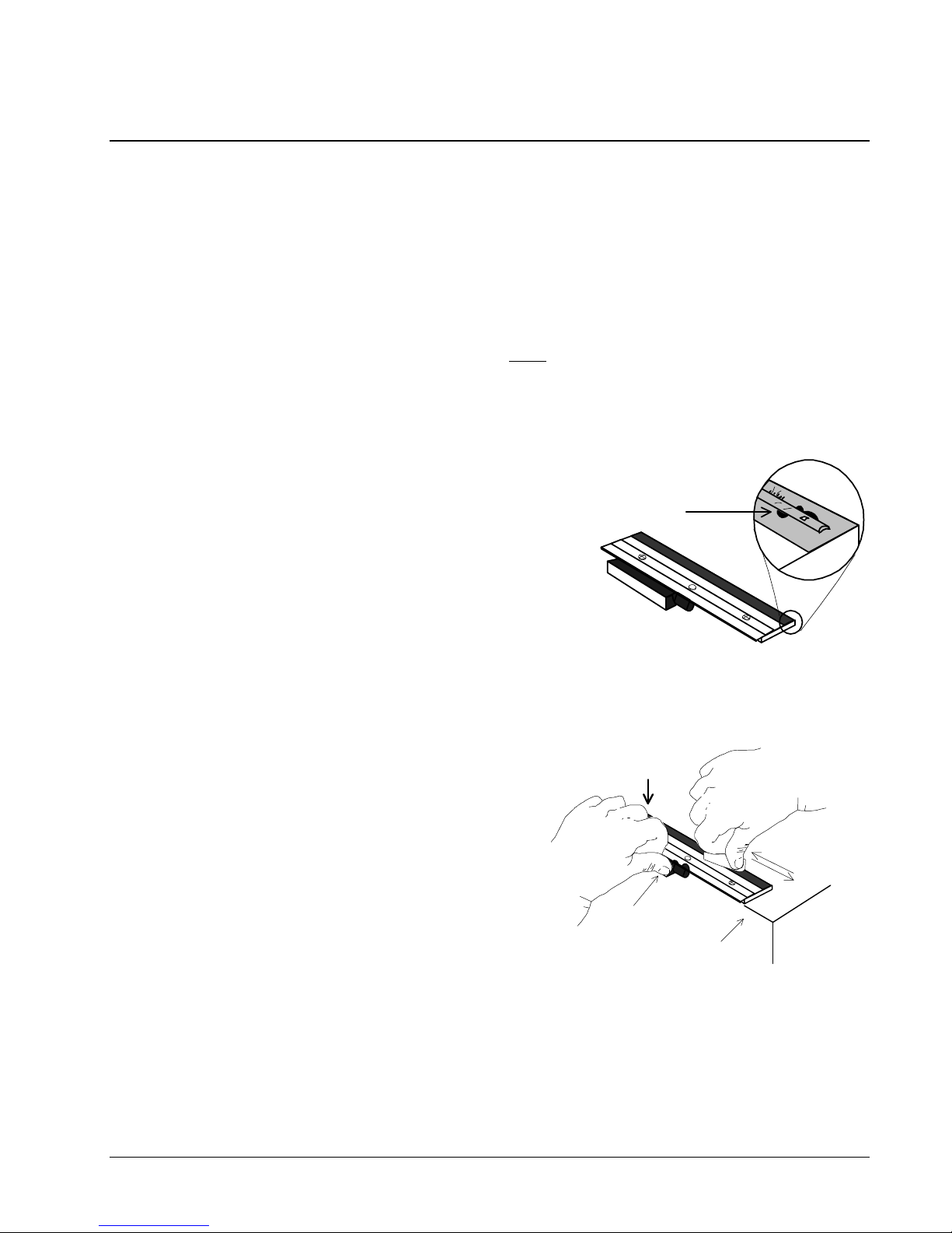
Printhead Cleaning Procedure
Printhead performance and life are influenced by proper handling and cleaning.
• Dirt on the printhead that causes problems is often too small to see.
• Exercise care in handling printheads, as they are very susceptible to static. Use the wrist grounding strap
and anti-static gloves when handling.
• It is OK to scrub the printhead HARD to clean it. Use rubbing alcohol and the “loop side” or “wool side” of
Velcro, followed by drying with rough, brown paper towels.
• If the printhead doesn’t work, take it out and clean it again.
• For maximum printhead life, clean the printhead after every roll change of ink or every 20,000 inches.
In Machine Cleaning Procedure
1. Stop the machine after the last batch has printed to avoid
loosing data.
2. Turn the machine off.
3. Open the printhead carriage assembly.
4. Soak a small amount of rubbing alcohol on a cotton swab
and apply to the printhead.
5. Scrub the printhead several times with hard force using the
“wool side” of Velcro.
6. Dry the printhead with a dry, brown paper towel.
7. Shut the printhead carriage assembly and resume printing.
8. If a problem continues, remove the printhead and clean it.
Dirt along the
print line.
Printhead cleaning when removed from the printer
1. Remove the printhead.
2. Place the printhead upside down on the edge of a clean
table with the connector pug over the edge of the table.
3. Soak a small amount of rubbing alcohol a cotton swab
and apply to the print line.
4. Scrub the printhead several times using HARD pressure
with the “loop side” of Velcro.
5. Dry with a dry, brown paper towel.
6. Replace the printhead.
Heavy finger
pressure here
Thumb here to
hold against
the table
Scrub here,
hard pressure
Table edge
Users Manual Model 686 / 686 HT Appendix E •••• 79
Page 82

Printhead Installation and Removal Procedures
Printhead removal procedure
1. Attach the grounding strap to your wrist and the printer.
2. Turn the machine off.
3. Leaving the printhead shut, completely loosen the two mount screws but
leave them loose in the holes.
4. Slowly open the printhead carriage assembly. Maneuver the printhead
down and to the right, pulling the wire pack out.
5. Disconnect the wire pack and carefully remove the printhead.
Printhead installation procedure
1. Position the printhead loosely under the printhead carriage assembly.
2. Connect the wire pack.
3. Position the printhead in the printhead carriage assembly so that the
alignment pegs match up and the printhead fits snugly.
4. Tighten the mount screws.
80 •••• Appendix E Users Manual Model 686 / 686 HT
Page 83
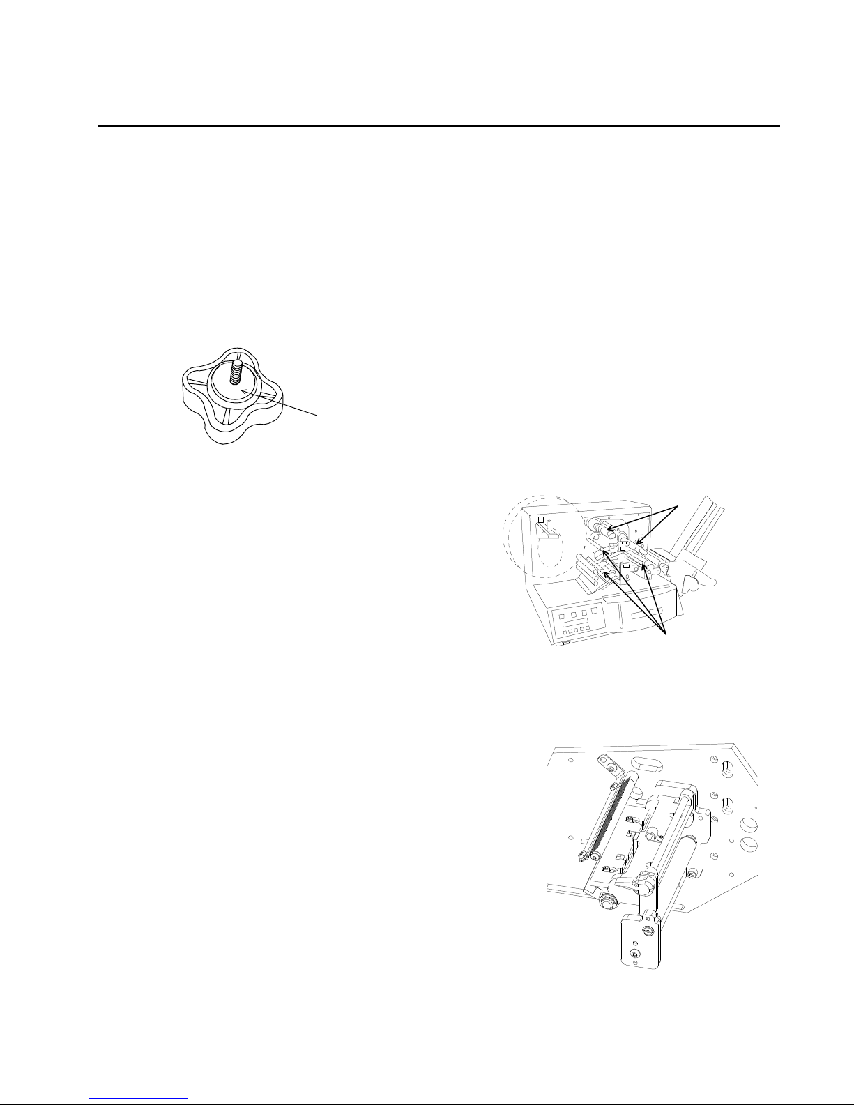
Static Checks for 686 / 686 HT Printers
1. Stacker: With an ohmmeter, check continuity between the main stacker
roller, which has the belts on it, and the chassis ground. Chassis ground
can be any screw near the serial cable. Check that these two important
enhancements are functioning:
a) Check the stacker-mounting knob has a
large washer installed. Make sure to tighten
Washer
Stacker knob removed
2. Ink arbors: With an ohmmeter, check for
continuity on the two ink arbors and three
ink turn rollers. Place one lead of the
ohmmeter on the arbor and the other on
the chassis ground screw.
3. Printhead Static Protections. Check for proper installation.
a) Static Brush. Make sure the brush is
installed and just barely touches the ink.
Too much dragging and they wear - too
little contact and they don’t dissipate the
static.
the knob all the way.
Ink arbors
Ink turn rollers
Users Manual Model 686 / 686 HT Appendix E •••• 81
Page 84

Print Quality Adjustment
1. Tangent is factory set and should not be adjusted. Head pressure is fixed without
adjustment.
2. Strobe - Adjust strobe for print darkness and bar code scanability. Adjust one
increment at a time.
82 •••• Appendix E Users Manual Model 686 / 686 HT
Page 85

Users Manual Model 686 / 686 HT Assembly Drawings •••• 83
Assembly Drawings
Page 86
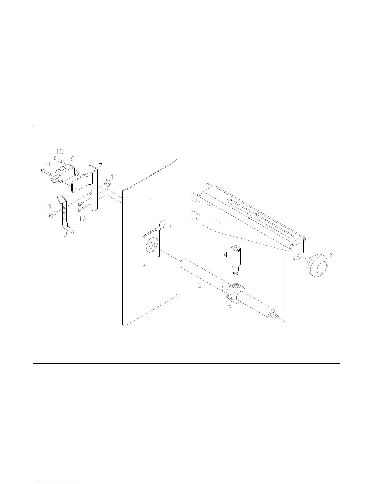
84 •••• Assembly Drawings Users Manual Model 686 / 686 HT
Unwind Assembly Drawing
Page 87

Users Manual Model 686 / 686 HT Assembly Drawings •••• 85
Unwind Parts List
Item Part # Description Qty
1 373012 Web guide, Rear 1
2 373009 Lead screw, Tape unwind 1
3 373011 Adjuster, Outer web guide 1
4 373010 Rod, Web guide, Outer 1
5 353002 Bracket, Unwind 1
6 105023 Impression adj, Knob / SS Kit 1
7 373014 Bracket, Sensor mount 1
8 373013 Bracket, Stock out 1
9 191120 Micro switch 1
10 989973 4-40 x ½ Cap screw 2
11 990069 8-32 Hex nut 1
12 990000 2-56 x ¼ Cap screw 2
13 990065 8-32 x 3/8 Button head screw 1
14 371142 Stock out switch harness (*ns) 1
15 990513 Small wire tie (*ns) 1
(*NS) = Not Shown
Page 88
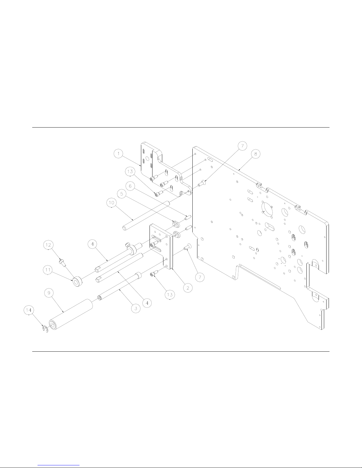
86 •••• Assembly Drawings Users Manual Model 686 / 686 HT
Unwind Turnbar Assembly Drawing
Page 89

Users Manual Model 686 / 686 HT Assembly Drawings •••• 87
Unwind Turnbar Parts List
Item Part # Description Qty
1 554014 Bracket, Unwind arm mount 1
2 554015 Bracket, Web roller mount 1
3 554017 Shaft, De-curler roller 1
4 554029 Web turn shaft 2
5 554016 Nut, Roller shaft lock 2
6 990138 1/4-20 x 3/4 Knurled cup point 2
7 990133 1/4-20 x 3/4 Flat head screw 2
8 551002 Frame, Upright 686, Ink save 1
9 514090 Assembly, Tape idler roller 1
10 194020 Web turn shaft 1
11 990374 Collar, 1/2 2
12 990484 1/4-20 x 1/2 Nylon slotted screw 2
13 990121 1/4-20 x 5/8 Cap screw 5
14 990328 E-ring, 1/2" 1
Page 90
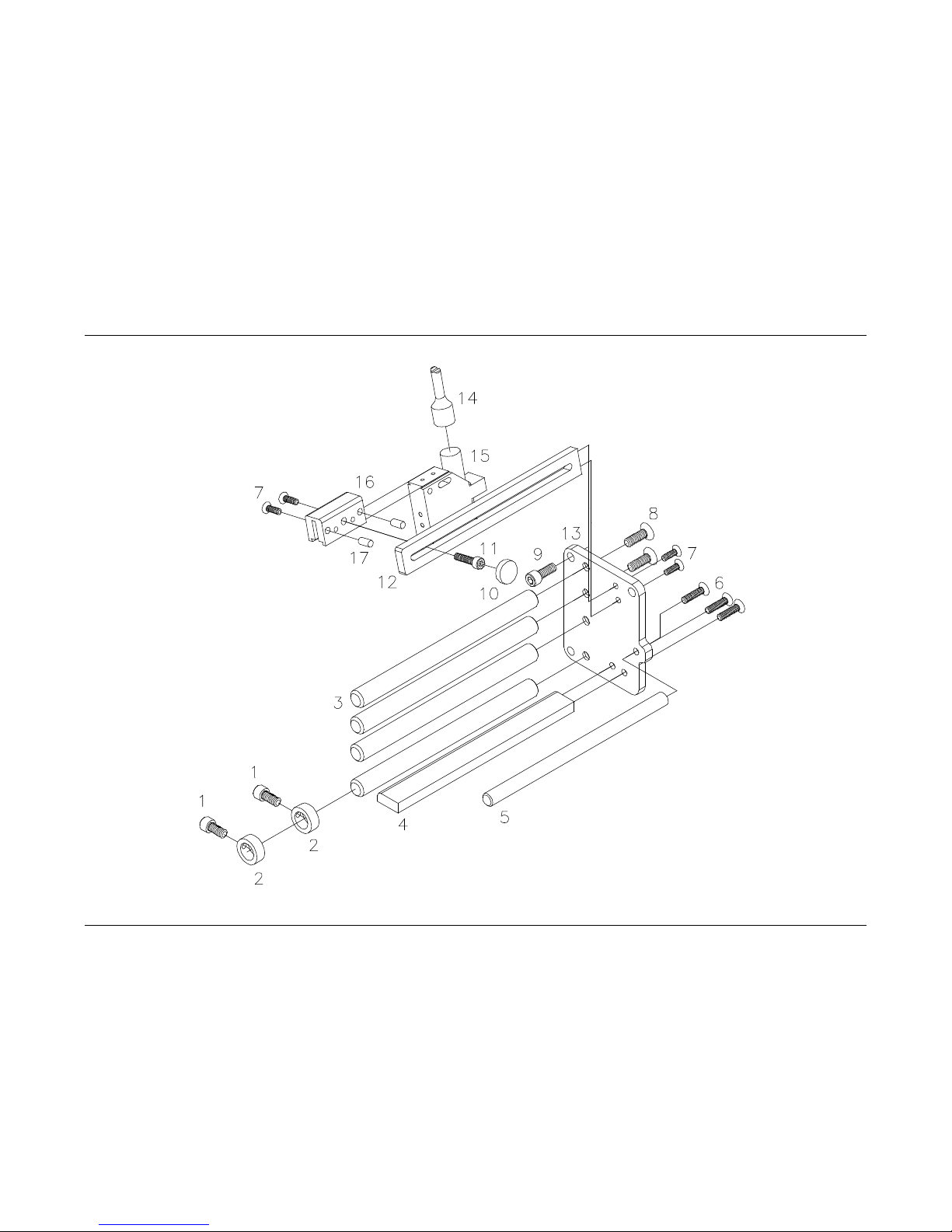
88 •••• Assembly Drawings Users Manual Model 686 / 686 HT
Contrast Sensor Assembly Drawing
Page 91
Users Manual Model 686 / 686 HT Assembly Drawings •••• 89
Contrast Sensor Parts List
Item Part # Description Qty Item Part # Description Qty
1 990484 ¼-20 x ½” Slotted Nylon screw 2 11 990083 10-32 x ¾” Cap screw 1
2 990374 ½” Collar 2 12 514019 Bracket, Sensor mount 1
3 194020 Web turn shaft 4 13 514016 Bracket, Sensor ass’y 1
4 514019 Bracket, Sensor guide 1 14 511112 Cable, Contrast sensor 1
5 514017 Shaft, Ink turn bar 1 15 281140 Scanner, Contrast 1
6 990111 10-32 x ¾” Flat head screw 3 16 514020 Sensor, Mount block 1
7 990056 8-32 x ½” Flat head screw 4 17 990268 3/16 x ½” Dowel pin 2
8 990133 ¼-20 x ¾” Flat head screw 5
9 990121 ¼-20 x 5/8” Cap screw 3 514098 Can Be Ordered As An Assembly
10 990313 #10 Thumb screw knob 1
Page 92
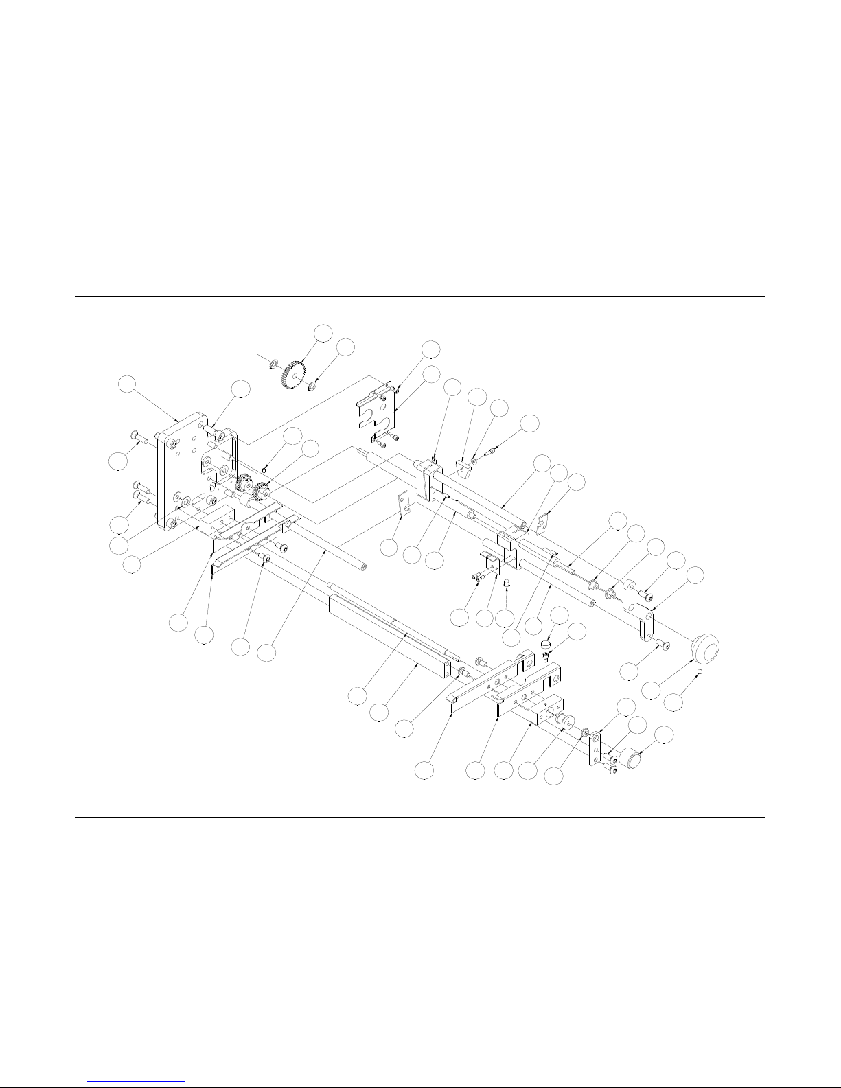
90 •••• Assembly Drawings Users Manual Model 686 / 686 HT
Web Guide
/
Sensor Assembly Drawing
18
19
6
27
15
21
8
34
32
31
25
30
18
33
36
35
11
27
1
12
13
26
28
2
19
14
5
10
23
2224
29
38
3
16
17
4
9
43
21
20
39
37
10
3
10
3
41
40
4
42
7
Page 93
Users Manual Model 686 / 686 HT Assembly Drawings •••• 91
Web Guide
/
Sensor Parts List
Item Part # Description Qty Item Part # Description Qty
1 554064 Drive, Sensor adjust gear 2
23 554005 Drive, Web guide adapter 1
2 554057 Cover, Gear cluster 1
24 554067 Bracket, Front (top) web guide 1
3 554088 Assembly, Bracket, Front plate 1
25 554069 Bracket, Front (bottom) web guide 1
4 554051 Shaft, Sensor adjust 2
26 990122 1/4-20 x 3/4 Cap screw 4
5 554053 Bracket, Mount, LED 1
27 990111 10-32 x 3/4 Flat head screw 5
6 554054 Bracket, Mount, Upper sensor 1
28 990007 4-40 x 1/8 Knurled cup point 2
7 554055 Nut, Plastic, Lower 1
29 196028 Adj knob / SS - Plain black 1
8 554056 Nut, Plastic, Upper 1
30 554009 Shaft, Web guide 1
9 554061 Bracket, LED secure 1
31 554004 Bracket, Web guide mount 1
10 990091 10-32 x 1/2 Button head screw 4
32 554066 Bracket, Back (top) web guide 1
11 554089 Assembly, Bracket, Web guide 1
33 554068 Bracket, Back (bottom) web guide 1
12 990262 Snap ring, 1/4" 2
34 990274 Washer, 1/4" Belleville 1
13 554065A Drive, Gear, Idler, Sensor adj alt 1
35 554003 Shaft, Web guide adjust 1
14 554058 Shaft, THD rod, Upper 1
36 554002 Bracket, Web adjust rod 1
15 554059 Shaft, THD rod, Lower 1
37 554007 Bracket, Web guide support 1
16 990015 6-32 x 1/4 Cap screw 1
38 999100 Bushing, FL 3/16 x 5/16 x 1/8 1
17 990312 #6 Thumb screw knob 1
39 105023 K**Impression adj. Knob 1
18 990090 10-32 x 3/8 Button head screw 4 40 371128 Top & bottom reflective sensor
harness
1
19 990006 4-40 x 1/4 Cap screw 6
41 990448 Washer, .125 x .313 x .031 FL 1
20 990058 8-32 x 1/4 Knurled cup point 1
42 990424 4-40 x 3/8 Cap screw 1
21 990008 4-40 x 3/8 Knurled cup point 2
43 551169 Sensor, IR LED wired 1
22 554006 Bracket, Web guide mount, Front 1
Page 94
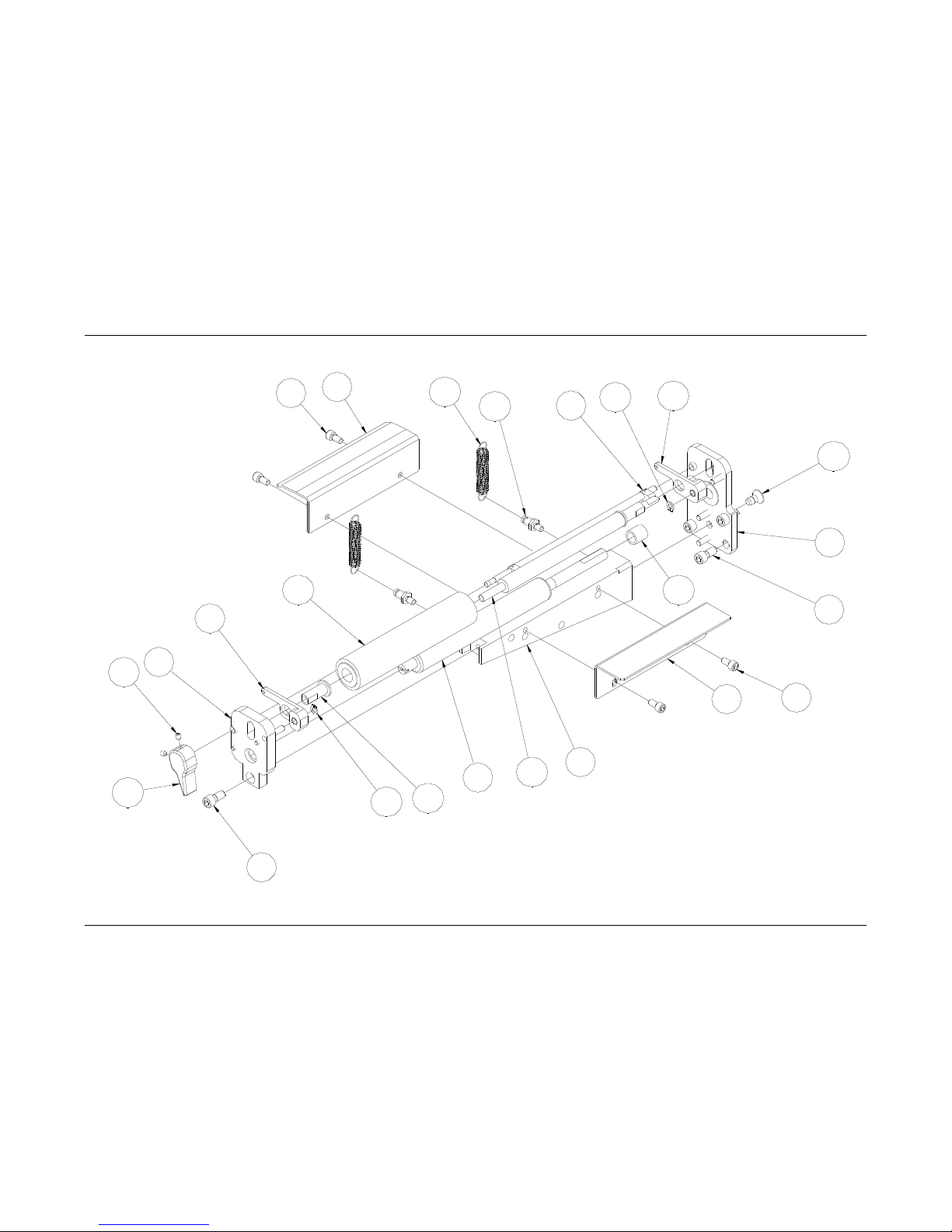
92 •••• Assembly Drawings Users Manual Model 686 / 686 HT
Drive Assembly Drawing
4
17
18
11
14
16
3
13
21
7
2
9
5
6
15
19
14
10
8
12
5
1
7
20
Page 95

Users Manual Model 686 / 686 HT Assembly Drawings •••• 93
Drive Parts List
Item Part # Description Qty
1 554099 Ass’y, Rear drive support 1
2 355018 Support, Knife / Drive / Print 1
3 554098 Ass’y, Front drive support 1
4 554042 Bracket, Right bridge blade 1
5 990080 10-32 x 3/8 Cap screw 4
6 554041 Bracket, Bridge plate (Web) center 1
7 990120 1/4-20 x 1/2 Cap screw 5
8 514094 Ass’y, Lift cam 1
9 354012 Roller, Grit 1
10 999146 Bushing, 3/8 x 1/2 x 1/2 1
11 514009K Spring lever, Front 1
12 514010K Spring lever, Rear 1
13 514012 Feed knob / SS 1
14 990261 Snap ring, 3/16 2
15 514003 Pin, Spring anchor 2
16 514002 Sleeve, Idler shaft 1
17 514001 Shaft, Idler roller 1
18 514090 Tape roller idler, Molded 1
19 991085 Extension spring 2
20 990416 1/4-20 x 1/2 Flat head screw 1
21 990058 8-32 x 1/4 Knurled cup point 2
Page 96
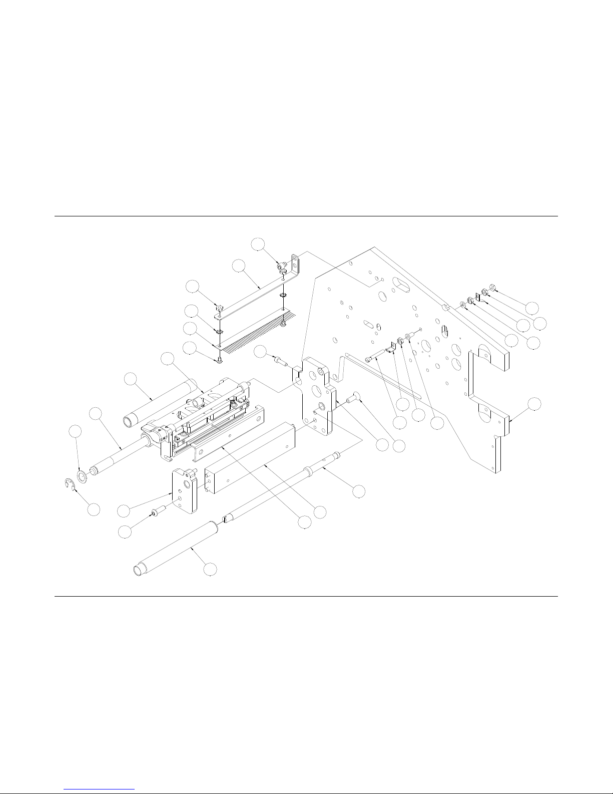
94 •••• Assembly Drawings Users Manual Model 686 / 686 HT
Printhead Assembly Drawing
14
14
26
14
16
14
13
20
15
9
1
11
12
2
10
7
17
21
22
14
23
24
25
6
18
3
19
8
4
5
Page 97
Users Manual Model 686 / 686 HT Assembly Drawings •••• 95
Printhead Parts List
Item Part # Description Qty Item Part # Description Qty
1 555099 Ass’y, Rear support, Print head 1
14 990069 Nut #8 6
2 375085 Ass’y, Support beam, Print head 1
15 990500 Bushing, Nylon 1
3 376032 Ass’y, Ink turn roller 1
16 990723 Washer#8, Nylon 1
4 990497 Washer, 1/2 Wave 1
17 555041 Bracket, Print head adjust 1
5 990328 E-ring, 1/2 1
18 551001 Frame, Upright 1
6 990083 10-32 x 3/4 Cap screw 1
19 555096K Kit, Ass'y print head, 686 printer 1
7 555098 Ass’y, Front support, Print head 1
20 990071 #8-32 x 1 1/4 FH machine screw 1
8 375014 Shaft, Head mount 1
21 516001 Bracket, Static brush ink 1
9 990133 1/4-20 x 3/4 Flat head screw 1
22 990118 1/4-20 x 1/4 Cap screw 1
10 990135 1/4-20 x 3/4 Button head screw 1
23 989978 Washer, #8 Star 2
11 555017 Shaft, Eccentric 686 ink save 1
24 355039 Static brush 1
12 355096 Ass’y, Print head roller 1
25 990066 8-32 x 1/4 Button head screw 2
13 375057 Contact, Ground 1
26 375019 Ring terminal, Male connector 1
Page 98
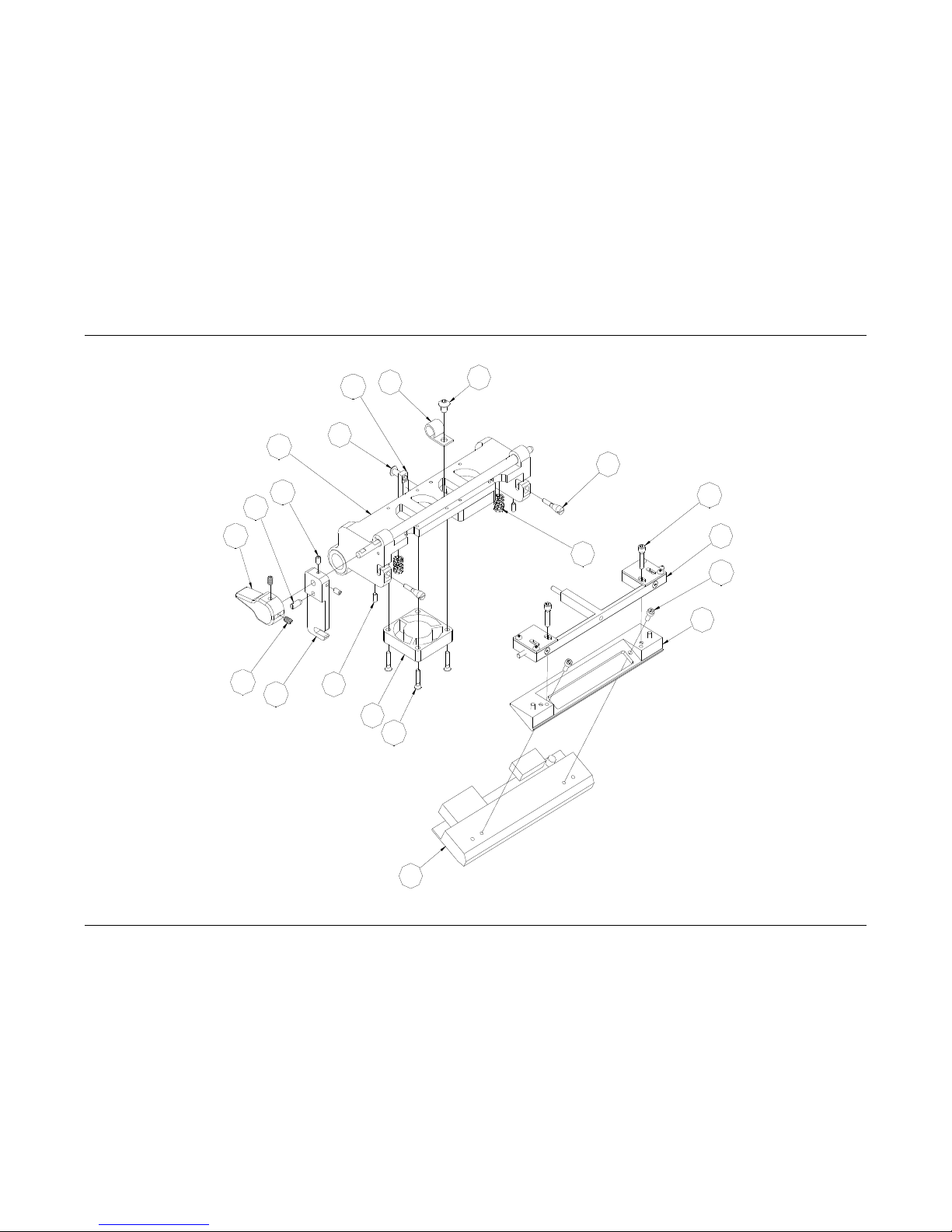
96 •••• Assembly Drawings Users Manual Model 686 / 686 HT
Printhead Module Assembly Drawing
3
5
13
14
10
2
12
16
17
15
18
6
8
7
11
4
9
19
1
20
Page 99
Users Manual Model 686 / 686 HT Assembly Drawings •••• 97
Printhead Module Parts List
Item Part # Description Qty Item Part # Description Qty
1 555030 Ass’y, Print head adjust 1 11 991331 Compression spring 2
2 551131 Fan, Print head, Harnessed 2 12 555006 Bracket, Lock 1
3 551102 Print head (For references) 1 13 991287 M3 x 8mm Cap screw 2
4 555034 Screw, Adjust 2 14 991333 6-32 x 5/8 S.H.C. Screw 2
5 555032 Assy. Print head mount 1 15 990025 6-32 x1/4 Set screw 2
6 990073 8-32 x 1/2 B.H.C. Screw 1 16 990058 8-32 x 1/4 Set screw 2
7 990089 10-32 x 1/4 B.H.C. Screw 1 17 514012 Knob, Head lift 1
8 990919 Bracket, Cable mount 1 18 555087 Ass'y, Print head holder, 686 1
9 991329 4-40 x 1/4 Set screw w/ Nylon 2 19 999092 Stubby spring plunger 1
10 991308 4-40 x 5/8 F.H.C. Screw 8 20 555014 Bracket, Rear head mount 1
Page 100
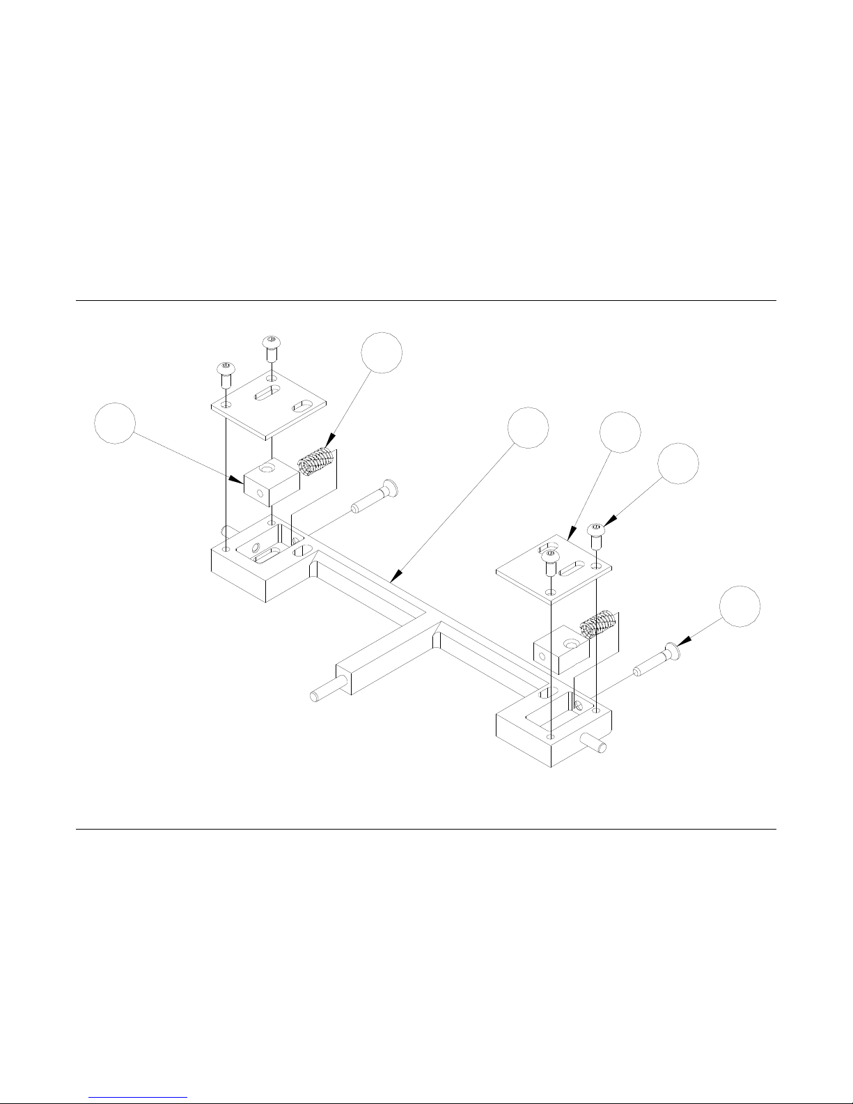
98 •••• Assembly Drawings Users Manual Model 686 / 686 HT
Printhead Adjustment Assembly Drawing
5
3
2
1
6
4
 Loading...