

Page 1

12/14 Rev. 03 USER MANUAL
64-xx
Commissioning & Operation
Mounting the Printer ...................................... 2
Unpacking the 64-xx ................................. 2
Carrying the 64-xx ..................................... 3
Mounting the 64-xx .................................... 4
Printer connections ................................... 5
Operator panel .......................................... 7
Operating modes ....................................... 9
Basic Operating Procedures ....................... 11
Connecting the printer ............................. 11
Switching on the printer ........................... 12
Configuring the data interface ................. 12
Offline operation ......................................13
Online operation ......................................14
Creating a print job ..................................15
Transferring a print job .............................15
Applying memory cards ...........................17
Setting the realtime clock .........................18
Outputting the realtime clock value using
Easy Plug .................................................18
Starting to print ............................................ 19
Settings for the material type ...................19
Printing the status report ..........................19
Page 2

12/14 Rev. 03 USER MANUAL Commissioning & Operation
64-xx
2
Mounting the Printer
Unpacking the 64-xx
1. Lift off the lid of the shipping box [1].
2. Take out the plastic bag containing the
accessories [1B].
3. Lift off the styrofoam support [1A].
4. Part the plastic cover [2].
[4] D o n ´t use the cutter as a handle!
5. Grab the printer from underneath and lift it
out. The material feed slot in the back wall
of the printer [3A] can be used as a
handle.
Printers with mounted cutter: The motor
[4B], but not the cutter [4A] may be used as
a handle!
6. Place the printer on a level surface in its
usual operating position (rubber feet [4C]
at the bottom).
The original packaging should always be
used for transporting the printer!
WARNING!
Printers with mounted cutter: The
cutter may cause cut injuries.
Do not grasp the cutter [4A] as a
handle.
Use the cutter motor [4B] as a
handle.
CAUTION! - Do not lift the printer by
the front cover [4B]. The front cover is
a movable part not designed for
handling stress.
[1] Shipping box without lid:
A Styrofoam support
B Accessories
[2] Open the plastic bag...
[3] Lift the printer out of the box.
A Back wall of printer (not visible)
B Front cover (do not use for lifting)
C Rubber feet
A B
B
C
A
A
B
Page 3

12/14 Rev. 03 USER MANUAL Commissioning & Operation
64-xx
3
Carrying the 64-xx
To carry the printer, put one hand under the base plate and the other into the
feed slot at the back of the printer.
[5] Carrying the 64-xx safely (A: back – grab by the feed slot, B: front – grab by the base pla-
te).
WARNING!
The 64-xx is a heavy printer. The weight depends on the printer type and
equipement and can vary from 20 kg (64-04/05) up to 29.5 kg (64-08 Dispenser).
A bad carrying technique can cause back injury.
Try to lift the printer in a safe way, for example by
– carrying it close to your body, and by
– bending your knees, not your back.
CAUTION! - Do not lift the printer by the front cover (window side), as this
can damage it!
A
B
Page 4

12/14 Rev. 03 USER MANUAL Commissioning & Operation
64-xx
4
Mounting the 64-xx
The 64-xx has been designed as a desktop printer, which means that it is
normally mounted in an upright position on a table [2]. Other sufficiently large,
level and sturdy surfaces can also be used as a base.
[6] The correct orientation of the 64-04.
WARNING!
When choosing a base for the printer, observe the following guidelines to
avoid dangerous operating conditions:
The base needs to be at least as deep and wide as the printer itself.
The surface needs to be level, solid and dry.
The printer’s fan and ventilation slits must not be obstructed, as the device
may overheat otherwise.
The printer must not be mounted in the immediate vicinity of other heat
sources.
The environmental conditions specified (temperature, air humidity, etc.)
need to be complied with.
The power cable should be run to the printer so that
– nobody will trip on it, and that
– the power plug can easily be pulled out if necessary.
Page 5

12/14 Rev. 03 USER MANUAL Commissioning & Operation
64-xx
5
Printer connections
[7] Back of the 64-xx with the following options installed: USI board (H), connector for remote
operator panel (I) and start/stop signal input (J).
A Card slot
For SD/MMC cards; is not yet supported
B Card slot
For CompactFlash cards; used for storing fonts, logos, graphics, etc.
C USB interface type B (device)
For transfer of print data
D 2x USB interface type A (host)
To connect devices (e.g. keyboard, scanner)
E RS232 interface
For serial transfer of print data
F Status-LED/Ethernet
G Ethernet interface
To connect to an „Ethernet 10/100 Base T“ network
CAUTION!
Add-on devices of an inferior quality may damage the printer!
Connect the printer only to devices that fulfil SELV (safety extra-low volta-
ge) circuit requirements acc. to EN 60950!
Only connect OEM devices.
A
B
C
D
E
F
G
H
I
J
K
LM
Page 6

12/14 Rev. 03 USER MANUAL Commissioning & Operation
64-xx
6
H Optional: Signal interface USI
• 4 inputs / 8 outputs
• Standard at „64-xx Dispenser A“
I Optional: Mini-DIN connector
To connect a remote operator panel
J Optional: start/stop signal input
• Standard at 64-xx Dispenser
• To connect a foot switch (signal starts printer) or a stacker (signal stops
printer)
K Centronics interface
For parallel transfer of print data (cable is inclusive)
L Power switch
Turns the printer on/off
M Mains power supply connector
Connection to a mains socket using the provided power cable
N Connector for peripheral devices
Admissible peripheral devices are:
• Cutter („Cutter 2000“)
• Rewinder („Rewinder 2000“)
• Applicator LTSI (with „64-xx Dispenser A“ only)
• Photoelectric switch at the dispensing edge (with „64-xx Dispenser M“ only)
[8] Connector (N) for peripheral devices.
N
Page 7

12/14 Rev. 03 USER MANUAL Commissioning & Operation
64-xx
7
Operator panel
[9] Operator panel of the 64-xx.
Display With 32 digits and two lines, the display shows the operating conditions (mo-
des) for parameters, values, status and errors. You can select the language
you want to use for the display. Backlighting ensures good legibility.
Button functions The buttons offer a multitude of operating functions. A logical menu structure
is used for operation. The meaning of each button varies according to the
operating mode and the menu item. Additionally, special functions have been
programmed for certain button combinations.
Depending on the modes and menu levels, the following functions apply for
each button:
Online button
• For switching between online and offline mode.
• For confirming entries, menu items and messages.
• For selecting print jobs and for entering values in standalone mode.
Cut button
• Triggers a cut. Requirements:
– Cutter fitted and activated.
– Printer offline.
• Also for accessing deeper levels within the menu structure and selecting
menu items.
• For decrementing values.
Feed button
• For feeding in material when the device is offline.
• For starting the printing process once the feed has been stopped (in online
mode).
• Also for accessing deeper levels within the menu structure and selecting
menu items.
• Increments values.
Prog button
• For accessing the parameter menu when offline.
• For stepping back through the parameter menu and/or exiting it.
• For more detailed descriptions of the button functions, please see
Display
Cut button
Online button
Feed button
Prog button
Page 8

12/14 Rev. 03 USER MANUAL Commissioning & Operation
64-xx
8
– Chapter Offline operation on page 13 and
Chapter Online operation on page 14
– In topic section Info-Printouts and Parameter
Remote operator
panel
64-0x Gen. 3 (or higher) machines can be equipped with a remote operator
panel. For this, the printer must provide the appropriate - optional - connector,
see chapter Printer connections on page 5. The connection can be retrofitted (see service manual).
The button functions are the same as those on the standard operator panel.
Exception: The on/off switch is not available at the remote control panel.
With the remote control panel connected, both panels are active and show
the same information.
[10] Remote operator panel (article number A8293)
CAUTION!
Manipulating both operator panels simultaneously can cause malfunctions.
Always use only one operator panel at a time to operate the printer. (Using
both operator panels alternately is admissible).
CAUTION!
If the connection cable is longer than 2.5 m, EMC-caused disturbances can
occur.
Only use the factory-installed cable.
Don´t extend the cable.
Page 9

12/14 Rev. 03 USER MANUAL Commissioning & Operation
64-xx
9
Operating modes
Offline mode Printer settings can be made when the device is offline. The offline mode is
normally active when the printer is switched on. Print jobs are received via
the selected interface but not processed.
To configure the printer so that it goes directly into online mode when switched on, set the parameter
SYSTEM PARAMETER > Active Mode to “Online”.
Online mode In online mode, print jobs are received and processed immediately. Possible
messages:
To stop printing, press the online button.
Message mode The printer uses status reports to signal an error or a particular operating sta-
tus. This message mode indicates that the printer is waiting to quit or for fault
clearance. When quitting, the printer switches from message mode to offline
mode (depending on the error and the progress of the last active process).
The status message 5001 (shown above) occurs when for example the printer is set for punched label material, but continuous form material without
punches has been inserted. In this case, the printer will continue to feed the
material for a few seconds before it generates an error message.
Status Reports: see topic section „Status Reports“.
OFFLINE 0 JOBS No jobs are waiting to be processed.
ONLINE 0 JOBS No jobs are waiting to be processed.
ONLINE 0: JOBS The current data transfer to the printer is shown on
the display. This is indicated by the dot on the bottom
right next to the number of loaded jobs.
Another point on half line height above the first
shows the interpreter status:
• No point: No data to interpete.
• Solid point: The interpreter is busy (still data left
in the spooler).
• Flashing point: The interpreter is waiting for data
required to complete a command (no data in the
spooler).
ONLINE 13 JOBS
Restcount: 25
During printing, the display also shows the number
of received print jobs (13) and the remaining number
of labels (25) to be printed in the current job.
ONLINE 13 JOBS
Restcount: endless
If a print job recognises an endless number of labels
to be printed, then the remaining number for this job
is also shown as endless.
Status 5001
No gap found
Messages are made up of the status number and a
brief descriptive text.
Page 10

12/14 Rev. 03 USER MANUAL Commissioning & Operation
64-xx
10
Standalone mode In standalone mode, print jobs are not transferred but saved on a plugin card.
They are started directly from the printer’s operator panel or via a connected
keyboard.
Standalone mode: see topic section „Advanced Applications“.
Page 11

12/14 Rev. 03 USER MANUAL Commissioning & Operation
64-xx
11
Basic Operating Procedures
Connecting the printer
1. Ensure that the printer is switched off (mains switch [11C] at “0” position).
2. Connect the mains cable [11B] that came with the printer to the mains
connector at the printer.
3. Connect the mains cable into a mains socket.
4. Using a suitable data cable [11A], connect the printer to a data host
1
.
[11] Sockets for data cable (here: Centronics) (A) and power cable (B).
Cables: Ordering numbers for suitable power or data cables can be found in
topic section „Accessories“.
WARNING!
The printer operates using mains voltage! Touching electrically live parts
can cause exposure to hazardous electrical currents and may lead to
burns.
Make sure that the printer is switched off before connecting the power ca-
ble.
Only operate the printer using the system voltage indicated on the name-
plate.
Only connect the printer to a grounded power socket fitted to authorised
standards.
The power cable should be run to the printer so that
– nobody will trip on it, and that
– the power plug can easily be pulled out if necessary.
1) e. g. computer or network
A
B
C
Page 12

12/14 Rev. 03 USER MANUAL Commissioning & Operation
64-xx
12
Switching on the printer
Turn on the printer using the power switch (set to position “1”). The following
sequence of messages is displayed:
If the parameter
SYSTEM PARAMETER > Turn-on mode is set to “Offline”, the printer
switches directly to offline mode when turned on.
CAUTION! - Wait at least 10 seconds between switching the device off and
on again, otherwise any modified parameter settings are not saved.
Configuring the data interface
By factory default, the 64-xx is set for data transfer via the USB interface.
Print data can also be transferred via the RS232, RS422/485
1
, USB,
Centronics
2
or Ethernet interface.
Choosing the port:
INTERFACE PARA >EASYPLUGINTERPR > Interface
Configuring the port:
• RS232: INTERFACE PARA >COM1 PORT > ...
• RS232/422/485 (optional): INTERFACE PARA >COM3 PORT > ...
• Ethernet: INTERFACE PARA >NETWORK PARAM. > ...
We recommend that your network administrator configures the network
settings.
• USB: no configuration required
Setting parameters: see topic section „Info-Printouts and Parameters“,
chapter “Using the Parameter Menu”.
Ethernet interface: Information about using it can be found in topic section
„Advanced Applications“.
System start... The boot loader is starting.
System start...
Start user prog
Valid firmware recognised, program is starting.
64-05
V 6.52
Printer type
Version number of the printer firmware
Memory: 64 MB
Flashcard: 32 MB
Internal RAM (here: 64 MB)
Optional RAM on the memory medium (here: 32 MB)
– only displayed if a memory medium (memory card
or USB stick) is connected.
OFFLINE 0 JOBS
Initialisation
Offline mode
ONLINE 0
JOBS
Online mode. The unit is ready for printing.
1) Only with installed I/O interface board (option)
2) Only with installed Centronics interface board (option)
Page 13

12/14 Rev. 03 USER MANUAL Commissioning & Operation
64-xx
13
Offline operation
• Switching from offline mode to online mode:
• Switch to online mode when the print job is stopped:
• Slow material and ribbon feed:
• Material travels backwards under the printhead:
• Reset:
• Access the parameter menu, see topic section Info-Printouts & Parameters
• Feed material until the next punch is reached or as long as the button is held
down:
• Standalone operation: Selecting a print job stored on a CF card (e.g.,
Testdat.FOR), see topic section Advanced Applications , chapter
„Standalone Operation“:
OFFLINE x JOBS ONLINE x JOBS
OFFLINE x JOBS
Stopped xx
ONLINE x JOBS
Stopped xx
OFFLINE x JOBS OFFLINE x JOBS
feeding…
OFFLINE x JOBS OFFLINE x JOBS
feeding…
OFFLINE x JOBS OFFLINE x JOBS
OFFLINE x JOBS PRINT INFO
OFFLINE x JOBS OFFLINE x JOBS
feeding…
OFFLINE x JOBS Choose a file
Testdat.FOR
Online
Online
Feed
Online
Cut Online
Cut Online
Feed
Prog
Feed
ProgOnline
Page 14

12/14 Rev. 03 USER MANUAL Commissioning & Operation
64-xx
14
Online operation
• Switching to offline mode:
• Setting the print contrast: Press the Feed button to increase and the Cut
button to decrease the print contrast.
• Interrupting the print job: The device will finish printing the current label.
• Switching to offline mode while the print job is stopped:
• Continuing the print job:
• Standalone operation: Selecting a print job stored on a memory medium
(e.g., Testdat.FOR), see topic section Advanced Applications , chapter
„Standalone Operation“:
ONLINE x JOBS OFFLINE x JOBS
ONLINE x JOBS Print contrast
xxx%
ONLINE X JOBS
Restcount XXX
ONLINE X JOBS
Stopped XXX
a
a) The message “Stopped xxx” alternates with “Press Feed”.
ONLINE X JOBS
Stopped XXX
OFFLINE x JOBS
ONLINE X JOBS
Stopped XXX
ONLINE X JOBS
Restcount XXX
ONLINE x JOBS Choose a file
Testdat.FOR
Online
Prog
Online
Online
Feed
ProgOnline
Page 15

12/14 Rev. 03 USER MANUAL Commissioning & Operation
64-xx
15
Creating a print job
Essentially, there are two ways of creating a print job: Either by using the
64-xx Windows printer driver, or by creating a text file using print commands.
Windows printer
driver
64-xx printer drivers are available for different versions of Windows. You can
print from nearly every Windows application using the printer drivers. However, functionality is strongly dependent on the choice of software. Special label layout programs are best suited, for example NiceLabel (a demo version
is included with the printer shipment).
The driver’s help function explains how to use the printer driver. The help
function of your Windows operating system will tell you how to install the
driver.
Printer drivers for the different versions of Windows can be found on the
Internet at (http://www.machines.averydennison.com/printersystems_gb.nsf/
wview/L4L3?OpenDocument)
Command file You can write a sequence of commands in a text file and send it to the printer.
To do this, you can use any text editor and the MS-DOS Copy command.
Easy Plug provides a special command language to program print jobs. However, writing a print job in text file format does require some programming
knowledge. Furthermore, you will not be able to preview the resulting printout
on the screen. Instead, you have to run a test print to see a copy of the finished result.
Easy Plug Manual: here you can find a practice example of a print job
together with instructions in the section “Program Example” in topic section
“General, Definitions Commands Overview”.
Transferring a print job
The printer can only carry out a print job once this job has been transferred
into the printer’s RAM. This can be accomplished in two ways: via a direct
transfer from your computer via a data cable or by saving it to a memory me-
dium (memory card or USB stick).
Data cable The print job can be transferred
• via the serial interface,
• via the parallel interface, or
• via the Ethernet connection.
To transfer data via the serial or parallel interface, connect the corresponding
ports on the host computer and the printer. Use the DOS window to send the
print job file to the interface:
• Serial interface (COM1): copy testjob.txt com1
• Parallel interface (LPT1): copy testjob.txt lpt1
• USB interface / Ethernet interface:
copy testjob.txt \\computername\sharename.
– computername = Name of the computer (e.g., “DM-ECH-0990”). In
Windows XP this can be found under START > SETTINGS > CONTROL
PANEL > SYSTEM > COMPUTER NAME.
– sharename = enter the name found under START > SETTINGS >
PRINTERS AND FAXES after clicking on a printer symbol and right-
Page 16

12/14 Rev. 03 USER MANUAL Commissioning & Operation
64-xx
16
clicking PROPERTIES > SHARE (in Windows XP). The sharename stands
for a printer, which is connected to a certain port. This is the USB port for
tranferring via USB and the TCP/IP port for transferring by Ethernet.
A few hints on using the USB interface:
The method described here does not work in Windows 98, Windows ME or
Windows NT 4.0.
The sharename has to comply with the MS-DOS formatting conventions (no
more than 8 characters, no symbols or spaces).
Ethernet interface: Information about using it can be found in topic section
„Advanced Applications“.
Before sending a print job from a text program, you need to ensure that the
correct printer driver has been installed.
Special label layout programs, such as NiceLabel, make this much easier.
These programs also require a driver to be installed.
Memory medium To load a print job from a memory medium, you need to copy the print job to
a memory medium into the directory \FORMATS.
Transferring print jobs via memory card: A detailed description can be found
in topic section „Advanced Applications“, chapter “Standalone Mode”.
Page 17

12/14 Rev. 03 USER MANUAL Commissioning & Operation
64-xx
17
Applying memory cards
The printer of the 64-xx series support the following memory card types:
• CompactFlash (CF) Typ I [12]
• SD [13]
1
• SDHC
Flawless functioning of the memory cards is only guaranteed for the types
distributed by Avery Dennison:
[12] CF card (article no. A7681).
[13] SD card (article no. A101465).
Applying CF/SD cards: see Plugin-card manual, topic section „Application“,
chapter „CF/SD cards“.
Inserting a memory
card
1. Switch off the printer. Wait for 5 seconds.
2. Insert the memory card [14A,B] with the labelled side facing to the right and
the contacts facing ahead into the card slot until it clicks into place.
Removing a
memory card
CF card:
1. Switch off the printer. Wait for 5 seconds.
2. Press the eject button slightly in a bit and release it.
The eject button pops out.
3. Press the now protruding eject button completely in to eject the memory
card. Remove the memory card.
1) SD and SDHC cards are supported with firmware version 6.35 or above.
CAUTION! - Observe the following guidelines to avoid damaging the printer
or the CF card.
Only use CF -cards approved by the manufacturer.
Always wait at least 5seconds after switching off the printer before remo-
ving or inserting the CF card.
When inserting or removing the CF card, never use force.
Wide guide notch
Slim guide notch
Contacts
Page 18

12/14 Rev. 03 USER MANUAL Commissioning & Operation
64-xx
18
SD card:
1. Switch off the printer. Wait for 5 seconds.
2. Press onto the memory card, until it unlocks. Remove the memory card from
the card slot.
[14] Inserting a memory card (A: CF, B: SD). If the memory card has been inserted correctly,
it will sit flush with the printer’s back wall (right).
Setting the realtime clock
The realtime clock in the 64-xx printers can be used, for example, to calculate and print the expiry date of a perishable product.
This is how you set the realtime clock:
1. Navigate to the
SYSTEM PARAMETER > Realtime Clock.
2. To enter the date and time, use the Cut button to shift the cursor, the Feed
button to change the parameter, and the Online button to save it.
Setting parameters: see topic section „Info-Printouts and Parameters“,
chapter “Using the Parameter Menu”.
Outputting the realtime clock value using Easy Plug
Use the following Easy Plug commands to output the current realtime clock
value:
• #YC realtime as text
• #YS realtime as barcode
• #DM download month names
Easy Plug manual
Realtime clock
dd.mm.yyyy hh:mm
dd = day, mm = month, yyyy = year, hh = hour,
mm = minute
A
C
B
Page 19

12/14 Rev. 03 USER MANUAL Commissioning & Operation
64-xx
19
Starting to print
Settings for the material type
The parameter settings described below provide the printer with the necessary information about the label material used. When printing from a layout
program, these settings are usually provided automatically by the printer
driver. For your first test prints, you need to configure them manually.
Material type
• The label material is “endless”, which means that it contains no punches/
perforations, breaks or reflex marks that could be recognised by the punch
sensor:
Set the
PRINT PARAMETER > Material Type to “endless”.
• The label material contains punches/perforations, breaks or reflex marks that
can be recognised by the punch sensor (so-called “punched” material):
Set the
PRINT PARAMETER > Material Type to “Punched”.
Material length Set the
PRINT PARAMETER > Material Length to the length of the material (in mm).
Material width Set the
PRINT PARAMETER > Material Width to the width of the material (in mm).
Only for punched/perforated material:
Type of punch
• Label material with breaks or punches:
Set the
SYSTEM PARAMETER > Sensor Type to “Punched”.
• Label material with reflex marks:
Set the
SYSTEM PARAMETER > Sensor Type to “Reflex”.
Setting parameters: see topic section „Info-Printouts and Parameters“,
chapter “Using the Parameter Menu”.
Printing the status report
A status report printout is a perfectly adequate printer test. The width of the
status printout can be set to 100 mm or 50mm. This should match the width
of the label material used. The length of the printout is 200 mm.
100 mm width Navigate to
INFO PRINTOUT > Printer Status.
The printout that is triggered spans a label length of 2x 200 mm, listing all of
the printer’s current parameter settings.
50 mm width Set the
SYSTEM PARAMETER > Print Info Mode to “Compact right”.
Navigate to
INFO PRINTOUT > Printer Status.
The printout that is triggered contains the same information as the wider printout, compressed to a width of 50 mm.
Density If the printout is not as black as you would like it to be, increase the print den-
sity as follows:
1. Press the Esc button while in online mode. Display:
2. By pressing the Cut/Feed buttons, you can increase or decrease the heat
energy of the printhead (in %).
Print contrast
60%
Page 20

12/14 Rev. 03 USER MANUAL Commissioning & Operation
64-xx
20
The heat energy should be kept as low as possible while retaining an acceptable printing result. A high level of heat energy reduces the lifespan of the
printhead.
Page 21

03/13 Rev. 5.08-01 USER MANUAL
64-xx – 64-xx dispenser
Setting up
Winding diagrams ......................................... 2
64-xx ......................................................... 2
Designation of parts .................................. 2
64-xx dispenser ......................................... 3
Designation of parts .................................. 3
Selecting ribbon/material .............................. 4
Label material ............................................ 4
Thermotransfer ribbon ............................... 4
Inserting material .......................................... 5
Inserting fan-folded material ......................... 8
Changing material ......................................... 9
64-xx ......................................................... 9
64-xx dispenser ......................................... 9
Inserting ribbon ........................................... 10
Material / Ribbon end ..................................11
Material end .............................................11
Ribbon end ..............................................11
Rewinder full ............................................11
Settings for all printers .................................12
Ribbon tension .........................................12
Material light barrier .................................13
Print head contact pressure ..................... 14
Adjusting the position of the print head ....15
Material parameters ................................. 16
Settings at 64-xx dispensers .......................17
Dispenser types .......................................17
Basic settings ...........................................17
Parameter settings for
„64-xx dispenser M“ .................................18
Parameters settings for
„64-xx dispenser A“ ..................................18
Index ............................................................19
Page 22

03/13 Rev. 5.08-01 USER MANUAL Einrichten
64-xx – 64-xx dispenser
2
Winding diagrams
The winding diagrams show the winding direction of material and ribbon
through the 64-xx or through the 64-xx dispenser printer. You must follow
this basic schema when inserting/changing material and ribbon.
Ribbon and material should only be inserted/changed by specially trained
personnel.
64-xx
[1] This is how to insert material and ribbon correctly in the 64-xx or Chess x.
Designation of parts
No. Designation No. Designation
1 Adjusting knob for print head
contact pressure
8 Feed roller
2 Ribbon roller 9 Adjusting knob for punch
sensor
3 Ribbon rewind mandrel 10 Pad rollers
4 Ribbon unwind mandrel 11 Ribbon deflector
5 Material unwinder 12 Opener
6 Print head 13 Material guide
7 Print roller 14 Dancer arm
[Tab. 1] Designation of parts on the 64-xx.
1
2
3
4
5
6
8
9
10
11
12
13
7
14
Z0124.cdr
Page 23

03/13 Rev. 5.08-01 USER MANUAL Einrichten
64-xx – 64-xx dispenser
3
64-xx dispenser
[15] This is how to insert material and ribbon correctly in the 64-xx dispenser (each of type M).
Designation of parts
No. Designation No. Designation
1 Ribbon unwind mandrel 11 Dispensing edge
2 Ribbon deflector 12 Feed roller
3 Print head 13 Deflection roller
4 Ribbon roller 14 Rewinder
5 Ribbon rewind mandrel 15 Adjusting knob for punch
sensor
6 Material unwinder 16 Locking lever
7 Dancer arm 17 Adjusting knob for print head
contact pressure
8 Material guide 18 Clutch release motor
9 Feed roller 19 Rewinder motor
10 Print roller 20 Opener
[Tab. 2] Designation of parts on the 64-xx dispenser.
Z0123.cdr
1
2
3
4
5
6
7
8
10
11
12
14
15
16
17
18
19
9
13
20
Page 24

03/13 Rev. 5.08-01 USER MANUAL Einrichten
64-xx – 64-xx dispenser
4
Selecting ribbon/material
Label material
When selecting the material, you must take 3 factors into account:
– the abrasive behavior of the surface structure of the material;
– the properties with regard to the chemical reaction when printing ink is
transferred;
– the temperature required to transfer the ink.
Abrasive
behavior
If the material is very abrasive, the print head becomes “worn down” quicker
than would normally be the case. This criterion is of particular importance in
thermoprinting. It is not so critical in the case of thermotransfer printing, as
the ribbon can be chosen to be somewhat wider than the material, ensuring
that the print head is protected across the entire width of the material.
Head
temperature
The same applies if the temperature of the print head is high. Material and
ribbon need longer to cool down, the print quality is more critical and the print
head will wear down sooner.
For papers with grammages greater than 240 g, it may be necessary to make
adjustments with regard to the contact pressure and the position of the print
head.
Thermotransfer ribbon
For ribbon, we recommend the following:
– the reverse side of the ribbon must have an antistatic, friction-reducing
coating (backcoating);
– ribbons must be specified for “near edge type print heads”;
– ribbons should be suitable for print speeds of up to 12 inch/sec.
(300 mm/s).
Ribbon without these properties can reduce the performance of the
printer and/or the print quality as well as damage the print head!
Page 25

03/13 Rev. 5.08-01 USER MANUAL Einrichten
64-xx – 64-xx dispenser
5
Inserting material
• 64-xx: Steps 1 to 8
• 64-xx dispenser: Steps 1 to 18
1. Open the hood of the unit.
2. Pull off the outer guide disk (1) of the
unwinder (2).
3. Creel material on the unwinder with the
corresponding adapter rings. The roll of
material should turn anti-clockwise when
unwinding.
4. Refit the outer guide disk of the unwinder.
5. Lay material around the dancer arm.
6. Set the material guide to the width of the
label material. To do this, loosen the
knurled screw on the underside of the front
material guide (3). Push the material guide
sideways. Tighten the knurled screw again
(Fig. 2).
7. Press the red opener (4) of the intake in
order to raise the pad rollers. With the
opener depressed, push the start of the
material through the material guide until it
is below the print head (Fig. 3).
8. Align the material so that it is taken in
straight. With the loading lever depressed,
position the pad rollers of the printing unit
in such a way that both rollers (5) sit symmetrically on the material. (The print head
has been removed in Fig. 4 to allow a better view).
CAUTION!
Rotating axles! These can pull
in and tear off hair, clothing
and jewelry.
– Do not operate the machine with
the hood open!
– Keep long hair, loose clothing,
jewelry etc. well away from the
machine!
1
2
3
4
Page 26
03/13 Rev. 5.08-01 USER MANUAL Einrichten
64-xx – 64-xx dispenser
6
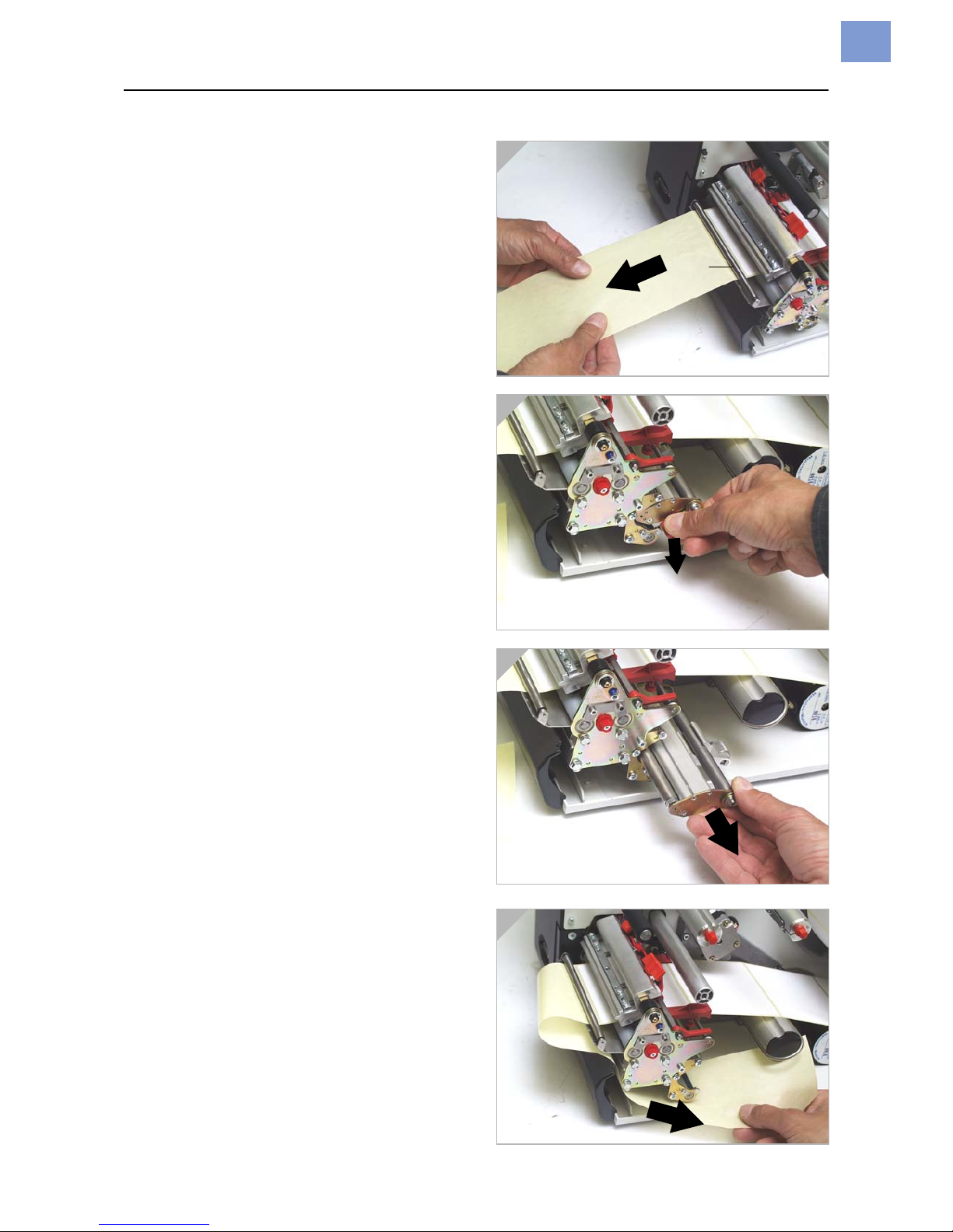
Only 64-xx dispenser:
9. Guide material through under the dispenser roller (1).
10. Pull labels off the backing paper over a
length of about 50 cm (Fig. 1).
11. Open the locking lever (press downwards,
Fig. 2) and swivel it half a revolution to the
rear.
12. Pull the drawing module (2) all the way out
(Fig. 3).
13. Guide the backing paper under the print
module to the rear (Fig. 4).
1
2
34
Page 27
03/13 Rev. 5.08-01 USER MANUAL Einrichten
64-xx – 64-xx dispenser
7
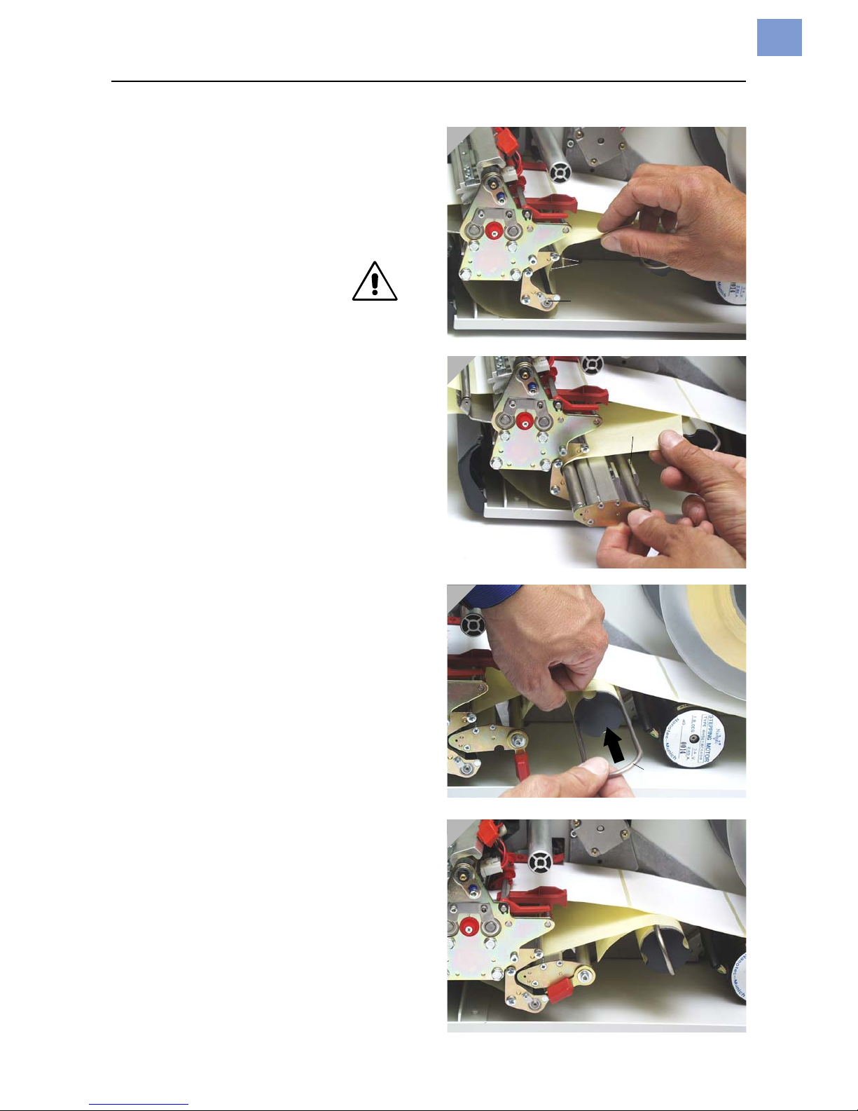
Continued on next page.
14. Guide the backing paper around the feed
roller (1) and guide pins (2) of the drawing
module to form an S shape (Fig. 1).
15. Put the drawing module back in again
(Fig. 2).
On insertion, it is essential
that the locking lever points to
the right (= half a revolution
open). Do not lock it until the
drawing module has been pushed in all the
way to the limit stop!
16. Wind the end of the backing paper clockwise around the rewinder (3) and fix with
the clip (4) (Figs. 3 and 4).
17. Position the block bearing the pressure
roller (5) in the middle of the backing
paper.
This is important for proper transport of
the backing paper around the dispensing
edge!
18. Lock the locking lever (Fig. 4).
1
23
4
Page 28
03/13 Rev. 5.08-01 USER MANUAL Einrichten
64-xx – 64-xx dispenser
8
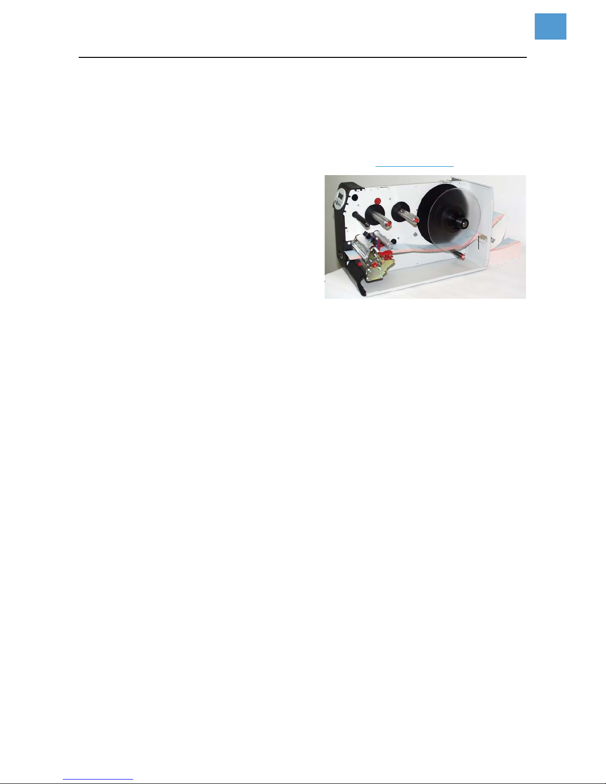
Inserting fan-folded material
1. Set the outer disc of the material unwinder to the width of the material.
2. Pull the material through the inlet opening (1) to the material guide with
the side to be printed showing upwards.
3. Then proceed as described in section Inserting material
on page 5.
[1] Pull the fan-folded mate-
rial through the inlet opening in the rear side and
proceed then as described
under „Inserting material“.
Page 29
03/13 Rev. 5.08-01 USER MANUAL Einrichten
64-xx – 64-xx dispenser
9
Changing material
Proceed as described in the following to
replace an inserted material roll befor it
comes to an end.
The printer must be switched on;
otherwise, the printhead presses on the
material.
64-xx
1. Switch the printer to offline mode and open
the front hood.
2. To remove the material, press the opener
while at the same time pulling the material
away to the rear (Fig. 2).
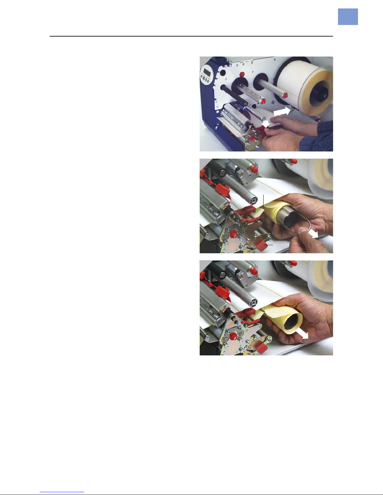
64-xx dispenser
1. Switch the printer to offline mode and open
the front hood.
2. Tear the backing paper off (2), pull out the
clip (Fig. 3) and remove the wound up
backing paper (Fig. 4).
3. Open the shutter (3) and pull out the
remaining backing paper towards the dispensing edge.
4. To remove the material, press the opener
while at the same time pulling the material
away to the rear (Fig. 2).
It is also possible to convey the material
backwards out of the print module by
pressing the Online+Cut keys in offline
mode.
1
2
3
Page 30
03/13 Rev. 5.08-01 USER MANUAL Einrichten
64-xx – 64-xx dispenser
10
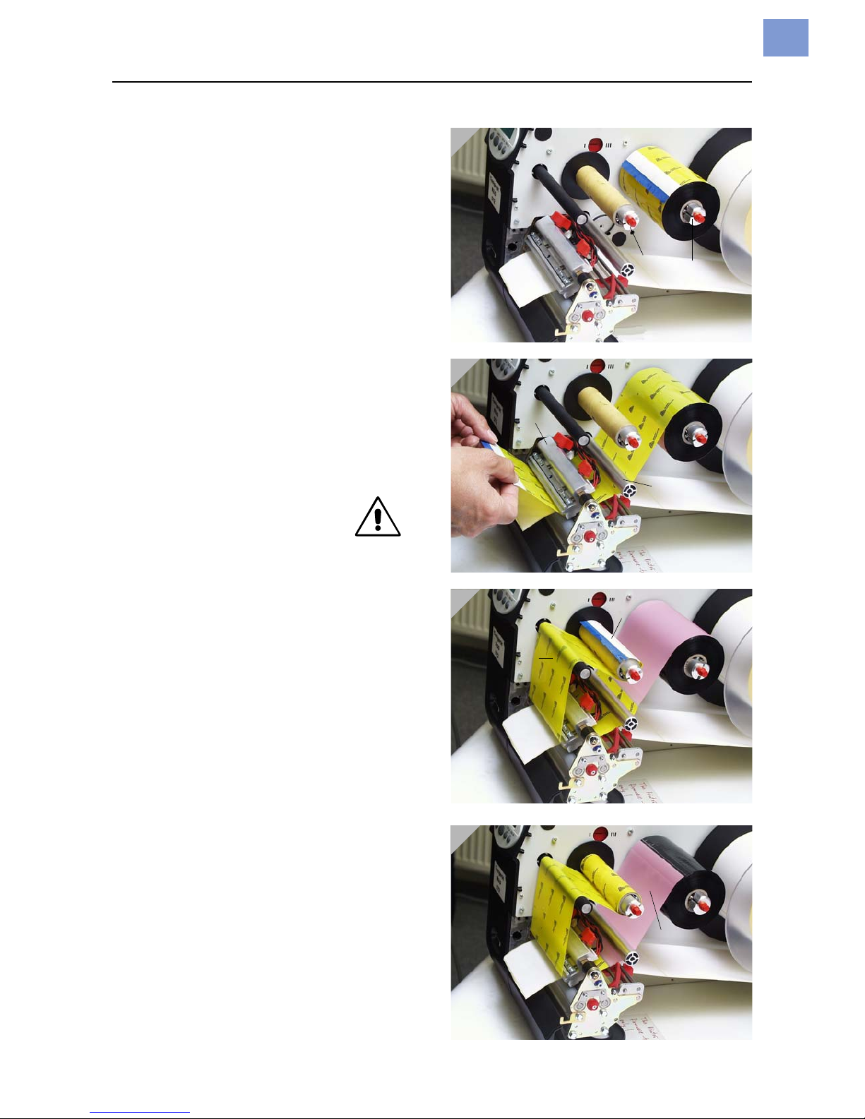
Inserting ribbon
1. Switch the printer on.
2. Open the hood of the printer.
3. Place the roll of ribbon on the right ribbon
mandrel (1) so that it can unwind anticlockwise.
4. Place the empty ribbon core on the left
mandrel (2).
5. Lead the end of the protective ribbon (yellow here) under the ribbon deflector (3)
and print head (4).
6. Then pull the (protective) ribbon upwards
and lay it over the ribbon roller (5).
7. Lead the (protective) ribbon under the
rewinder mandrel (2) and secure it on the
empty ribbon core using the self-adhesive
strip (6) (Fig. 3).
In many types of ribbon, the
protective ribbon (shown in
yellow in the illustration) is
followed by a strip of cleaning
ribbon (7) which serves to remove
contamination from the print head. It is
essential that the material is inserted as
described so that the cleaning effect is
guaranteed!
8. Check that the ribbon is free of folds and is
running true. Tension the ribbon by hand if
necessary.
1
2
3
4
Page 31

03/13 Rev. 5.08-01 USER MANUAL Einrichten
64-xx – 64-xx dispenser
11
Material / Ribbon end
Material end
If the material end has passed the material guiding, the following status
message appears:
1. Press the opener and pull the remaining material from the front side
(display side) out of the print unit.
2. Only dispenser version:
Open the shutter and pull the remaining backing paper in direction
rewinder out of the print unit.
3. Take the clip off the rewinder and remove the wound up backing paper.
For additional information read section Changing material on page 9.
Ribbon end
If the ribbon roll is emptied, that is the ribbon unwinding mandrel stopped
turning, the following status message appaers:
Proceed as described in section Inserting ribbon
on page 10.
The ribbon end detection can be switched off, e.g. for thermal printing.
To do so, set the parameter
SYSTEM PARAMETERS > Ribbon autoecon. to „ther-
mal printing“.
Rewinder full
Only for dispenser versions!
The dispenser rewinder can wind up the backing paper of a roll with
210 mm outer diameter and 4“ (102 mm) core inner diameter. If the maximum capacity of the rewinder is reached, the following status message
appears:
Proceed as described in section Changing material
on page 9.
Best clear the rewinder after every printed material roll!
Status 5002
Material end
Status 5008
Ribbon end
Status 5064
Rewinder full
Page 32
03/13 Rev. 5.08-01 USER MANUAL Einrichten
64-xx – 64-xx dispenser
12
Settings for all printers
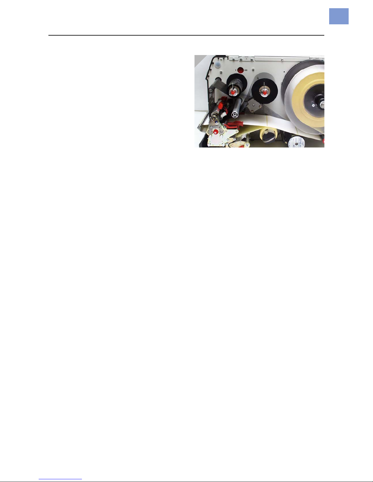
Ribbon tension
The torques of the ribbon unwind mandrel
(1) and ribbon rewind mandrel (2) can be
set using the red plastic hexagons on the
ribbon mandrels. If these are turned
clockwise, the torque increases (Fig. 1:
dispenser version).
Factory settings
The factory setting covers a wide range of
different ribbon widths, but very narrow or
very wide ribbons may necessitate
readjustment.
Setting
During feeding, the ribbon must run evenly
and free of folds for the entire length between the mandrels. The following
guidelines will facilitate setting:
The ribbon is loose or creased or is wound
on the rewind mandrel too loosely.
Increase the unwind/rewind torque (Turn
the red hex nut clockwise).
The ribbon visibly stretches or tears during
printing. The ribbon is inadequately
transported.
Decrease the unwind/rewind torque (Turn
the red hex nut counter clockwise).
More details about setting the ribbon ten-
sion can be found under “Adjusting the
ribbon brake” in the “Service print module”
section of the 64-xx service manual.
1
Page 33
03/13 Rev. 5.08-01 USER MANUAL Einrichten
64-xx – 64-xx dispenser
13
Material light barrier
The series 64-xx printers are fitted with transmitted-light light barriers.
Reflector light barriers are also available as an option.
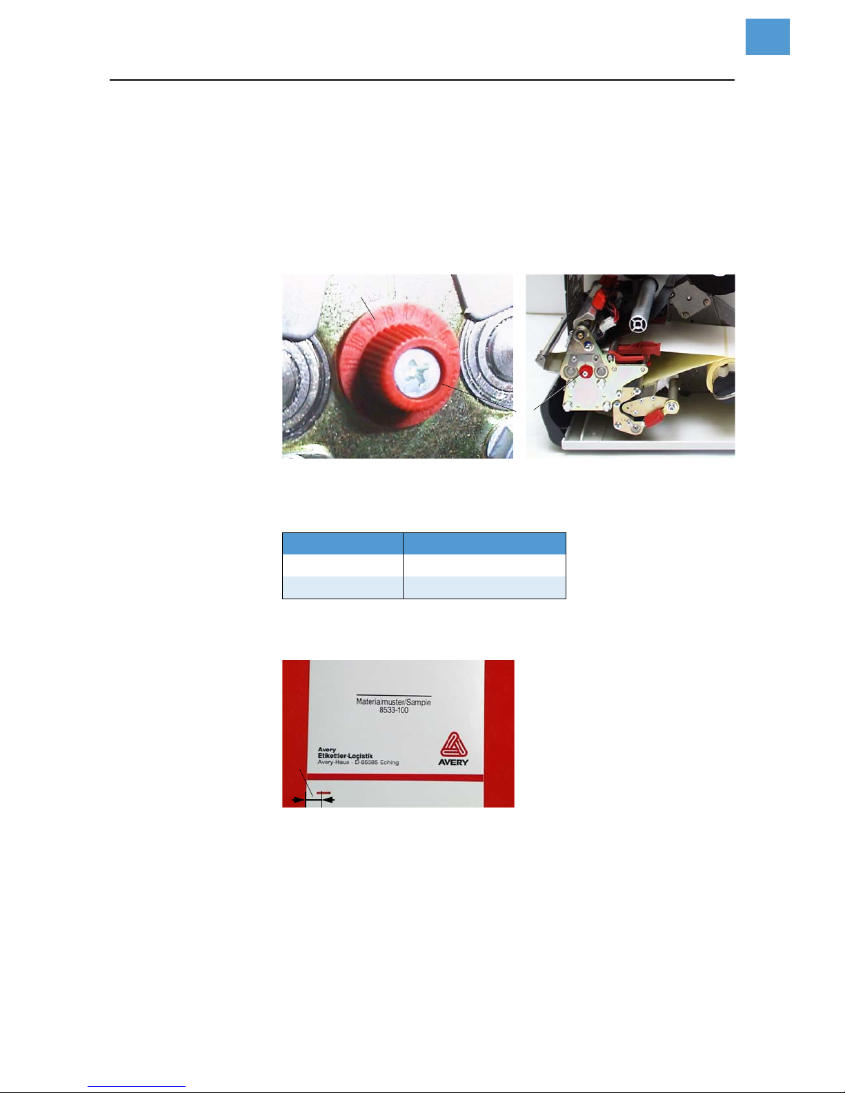
To set Setting is performed by means of the red rotary knob (1) on the outside
of the print module. The light barrier can be adjusted in a range of 15 mm
transverse to the material by turning the rotary knob. A dial (2) shows the
setting value from 0 to 15.
[1] The red adjusting knob (1) is used to adjust the lateral position of the punch light bar-
rier (figure: dispenser version).
Setting value
[2] Punch position = distance of punch center from (inner) edge of material (3).
To set, turn the rotary knob (1) until the desired setting value is opposite
the marking.
Example (for transmitted-light light barriers) center of punch from left edge =
11 mm, from which 2 mm deducted, giving a setting value of 9 mm.
For round labels, it is possible to perform a preliminary setting of the
punch offset manually on the printer (parameter
PRINT PARAMETERS > X –
print offset
) or by activation in order to capture the start of the labels
correctly.
Light barrier Setting value =
Transmitted light Punch position - 2 mm
Reflector Punch position - 13 mm
[Tab. 1] How to determine the setting value for the punch light barrier. (Punch position
= distance of punch center from (inner) edge of material (3); setting value =
dial value to be set by turning the red wheel)
Page 34
03/13 Rev. 5.08-01 USER MANUAL Einrichten
64-xx – 64-xx dispenser
14
Print head contact pressure
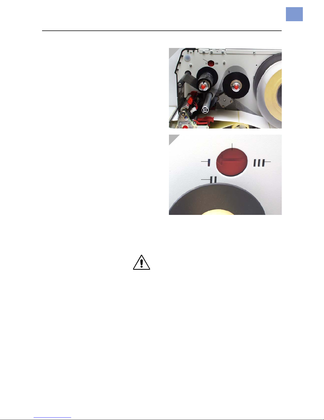
Different material widths and/or material
thicknesses have an effect on the contact
pressure of the thermal strip on the feed
roller.
The contact pressure can be set in 3 steps:
I Position for 64-04/05 or for thin/narrow
material up to the maximum print width of
the 64-05 (1)
II Position for 64-06 or for average material
up to the maximum print width of the
64-06 (2)
III Position for 64-08 or for thick/wide mate-
rial up to the maximum print width of the
64-08 (3)
To set:
The red adjusting screw (4) sits above the
ribbon roller and can be turned by means of
a coin.
For medium head contact pressure, turn
the arrow to position II until it engages.
For greater head contact pressure, turn the
arrow to position III until it engages.
Always choose the lightest contact
pressure that will produce an acceptable
printing result. This will help to protect the
print head and the entire unit.
Excess contact pressure
can lead to premature wear on
the print head.
Factory setting:
Position 1, thin/narrow material
1
2
Page 35
03/13 Rev. 5.08-01 USER MANUAL Einrichten
64-xx – 64-xx dispenser
15
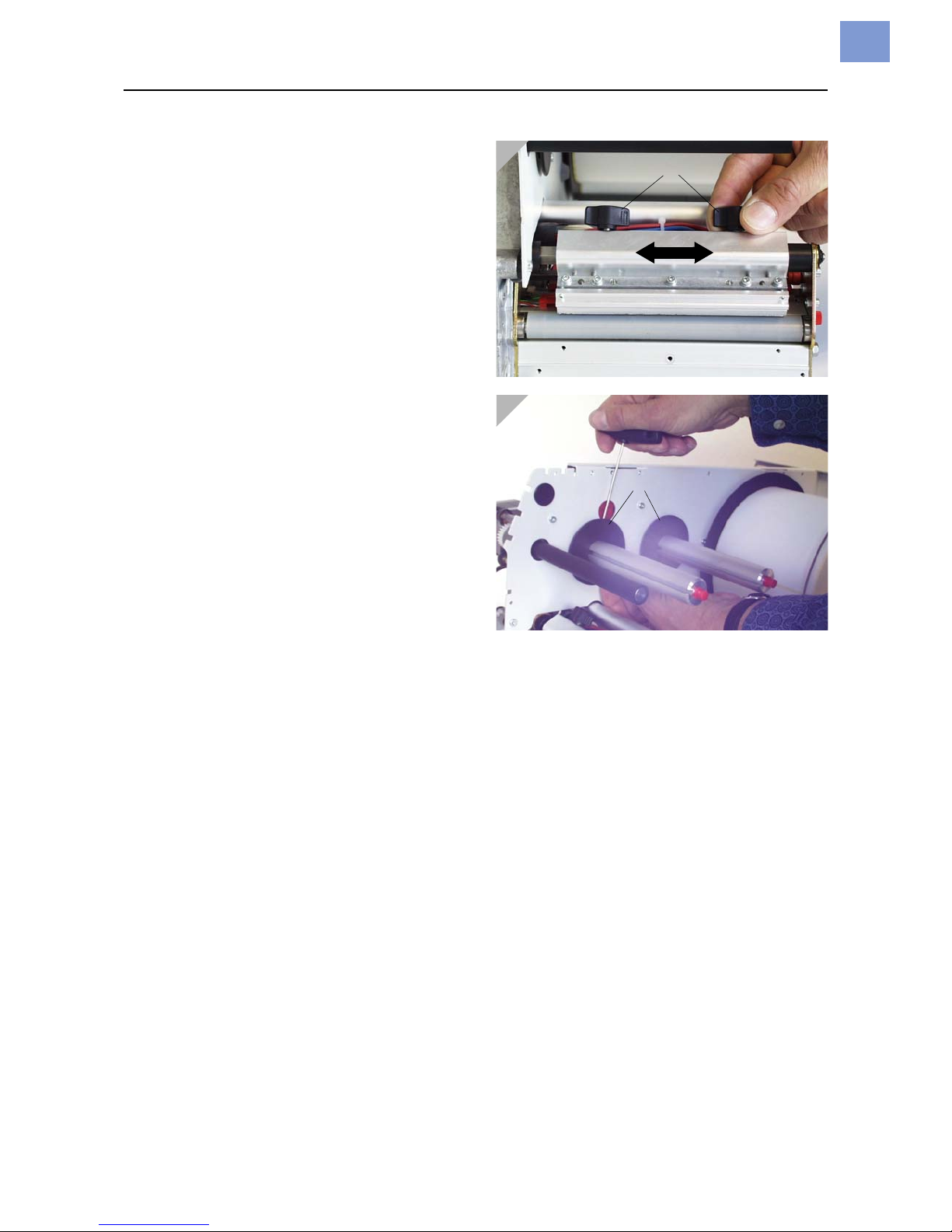
Adjusting the position of the
print head
Only for the standard version of 64-05/
06/08!
The print head 0 line can be adjusted variably from 2 mm (from the left edge of the
label) to 13 mm:
1. Loosen both thumb screws (1) and push
the print head to the desired position.
The print head does not have to be
taken off!
2. Tighten the screws again.
3. Loosen the stud screws at the black plastic
disks (2) using a 2 mm allen key (one
screw per disk).
4. Adjust the plastic disks to the same position as the inside of the print head.
5. Tighten the stud screws again.
1
2
Page 36
03/13 Rev. 5.08-01 USER MANUAL Einrichten
64-xx – 64-xx dispenser
16
Material parameters
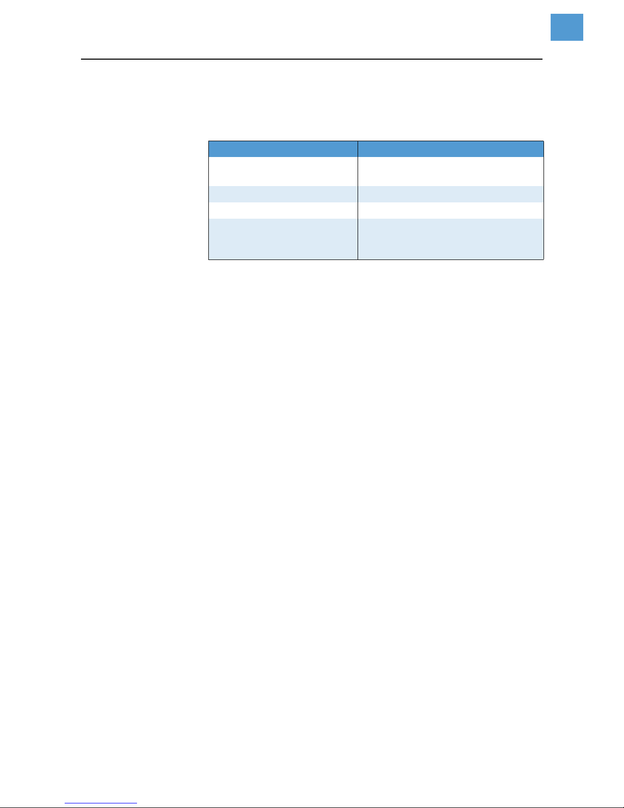
The following three parameters are used to tell the printer the properties
of the label material with which you would like to work:
Advice on setting parameters can be found under “Operating the
parameter menu” in the topic section “Info printouts and parameters”.
Parameter Function
PRINT PARAMETER > material type
Sets the type of material (punched or
continuous)
PRINT PARAMETER > material length
Sets the length of material
PRINT PARAMETER > material width
Sets the width of the material
SYSTEM PARAMETER > light sens. type
Sets the type of light barrier (reflector
or transmitted light) suitable for the
material (marks or punches)
[Tab. 1] Important parameters for setting material properties
Page 37

03/13 Rev. 5.08-01 USER MANUAL Einrichten
64-xx – 64-xx dispenser
17
Settings at 64-xx dispensers
Dispenser types
The 64-xx is available as „Dispenser M“ or „Dispenser A“ (see tab. 2).
Basic settings
The following table shows a basic setting for those parameters which are
most important for dispenser operation (see tab. 3). The setting can be
applied to both, type M and type A, with the purpose of using a
footswitch.
It is not possible to connect two foot switches to the printer (USI and
Single Start) and use them simultaneously.
Advice on setting parameters can be found in topic section Info printouts
and parameters.
Type Property Operating mode
64-xx Dispenser M
• Short dispensing edge with
label sensor
• Connector for start/stop
signal (e. g. for footswitch)
Printing/dispensing is triggered manually
(single start), e. g. by a footswitch. The
dispensed labels are taken off by hand.
Alternatively: Printing/dispensing is triggered by the label sensor, if a dispensed
label is taken off.
64-xx Dispenser A
• Long dispensing edge
without label sensor
• Connector for start/stop
signal (e. g. for footswitch)
Printing/dispensing is triggered manually
(single start), e. g. by a footswitch. The
dispensed labels are taken off by hand.
Alternatively: The dispensed label is taken
over by an applicator.
[Tab. 2] Different configuration of „Dispenser M“ and „Dispenser A“.
Submenu Parameter Setting
SYSTEM PARAMETERS
Periph. device Dispenser
External signal Singlestart
Start print mode Pulse rising
DISPENSER PARA
Dispense Mode Real 1:1 Mode
Dispensposition 0 mm
Dispensing mode fast
Application mode Immediate Mode
Start source Foot switch
Dispensing edge short
Transport mode Dispenser motor
[Tab. 3] Basic setting of the parameters most important for dispenser operation - valid
for both dispenser versions.
Page 38

03/13 Rev. 5.08-01 USER MANUAL Einrichten
64-xx – 64-xx dispenser
18
Information about operation with start signal can be found in topic section
Advanced Applications
, chapter „Printing with start signal“.
Parameter settings for „64-xx dispenser M“
The printing/dispensing process can be triggered by foot switch or by
light barrier:
Foot switch The values preset by the manufacturer (see tab. 3) are valid for manual
triggering of the printing/dispensing via the Single-Start connector, e.g.
using a foot switch. After pressing the foot switch, one label is printed and
dispensed.
Set
DISPENSER PARA > Start source to „Foot switch“.
Light barrier The dispensed label triggers a light barrier. This stops the printing/
dispensing until the user takes the label off. Then, the printer moves the
material back under the print head (only if „Real 1:1 Mode“ is selected,
see parameter
DISPENSER PARA > Dispense Mode) and prints and dispenses
the next label.
Change the basic parameter setting as follows to use the light barrier for
triggering:
Set
DISPENSER PARA > Start source to „Light barrier“.
Parameters settings for „64-xx dispenser A“
„64-xx dispenser A“ is equipped with a longer dispensing edge which leaves enough space for closing the hood if an applicator is mounted. This
long dispensing edge has no light barrier.
Applicator The „64-xx dispenser A“ is designed to be used with the LTSI applicator.
Advice on printer operation with the LTSI applicator, see Service manual
LTSI.
Advice on setting parameters can be found in topic section Info printouts
and parameters.
Information about operation with start signal can be found in topic section
Advanced Applications
, chapter „Printing with start signal“.
Page 39

03/13 Rev. 5.08-01 USER MANUAL Setting up
64-xx – 64-xx dispenser
19
Index
C
Changing material
9
D
Designation of parts
- 64-xx
2
- 64-xx dispenser
3
Dispenser
- parameters for version A
18
- parameters for version M
18
Drawing module
7
F
Fan-folded material
8
Foot switch, use two switches simultaneously
17
I
Inserting Material
5
Inserting ribbon
10
L
Label material
4
M
Material end
11
R
Rewinder full
11
Ribbon end
11
S
Setting label material parameters
16
Setting the material light barrier
13
Setting the position of the print head
15
Setting the print head contact pressure
14
Setting the ribbon tension
12
T
Thermoprinting ribbon
4
W
Winding schema
- Dispenser version
3
- Standard version
2
Page 40

11/14 Rev. 03 USER MANUAL
AP 4.4 – AP 5.4 – AP 5.6 – AP 7.t – 64-xx – DPM – PEM – ALX 92x
Advanced Applications
Printing with temperature compensation ....... 2
Requirements ............................................ 2
Function description .................................. 2
Printing with start signal ................................ 4
Application notes ....................................... 4
Available interfaces ................................... 4
Connecting the signal source .................... 5
Settings in the parameter menu ................ 7
Standalone Operation ................................... 8
Requirements ............................................ 8
Functional Description ............................... 9
Selecting files from memory card ............ 10
Executing printjobs .................................. 11
Executing firmware files .......................... 13
Automatic file execution .......................... 13
Additionally usable keys on a keyboard .. 13
Insert Input Field in Printjob .................... 14
Example Application ................................ 14
Data input by interface ............................ 16
Data Transmission with Ethernet ................ 17
System Requirements ............................. 17
Integration of Ethernet Interface .............. 18
Setting the IP Parameters ....................... 19
Transmission with Raw Socket Interface 19
Transmission with LPD Server ................ 20
Troubleshooting ...................................... 20
Access via Web/FTP server .......................21
Web server ..............................................21
FTP server ...............................................25
Data transmission with WLAN .....................28
Requirements ..........................................28
Notes .......................................................28
Printer setup ............................................29
Connecting ...............................................29
PC setup ..................................................30
Testing the connection .............................31
Sending a printjob ....................................31
Storing and transferring parameter settings 32
Recommendations ...................................32
Application cases ..................................... 32
Storing settings on memory card .............33
Loading settings from memory card ........34
Automatic setup loading ..........................34
Verifying Bar Codes with OLV .....................35
System Requirements .............................35
Functional Description .............................35
Setup .......................................................36
Appendix .....................................................38
Example: Setup file for AP 5.4 .................38
Page 41

11/14 Rev. 03 USER MANUAL Advanced Applications
AP 4.4 – AP 5.4 – AP 5.6 – AP 7.t – 64-xx – DPM – PEM – ALX 92x
2
Printing with temperature compensation
Requirements
• Suitable printers: All devices listed in the headline of this document
• Firmware: All versions
Function description
The print contrast is heavily dependent on the temperature of the printhead. This can
be set using the parameter SYSTEM PARAMETERS > Print contrast or in the online mode
after pressing the Esc button.
When the printer is being used for a big print job, the temperature of the printhead and
the print contrast increase during printing. This increase is greater, the larger the printjob and the larger the amount of black to be printed.
In extreme cases, this rise in temperature can lead to smearing in fine structures when
printed, e.g. barcodes arranged crosswise to the printing direction. To avoid this, the
firmware constantly checks and corrects the printhead temperature. The precondition
for this is that the parameter SYSTEM PARAMETERS > Temp. reduction is set to a value > 0
(Default: 20%).
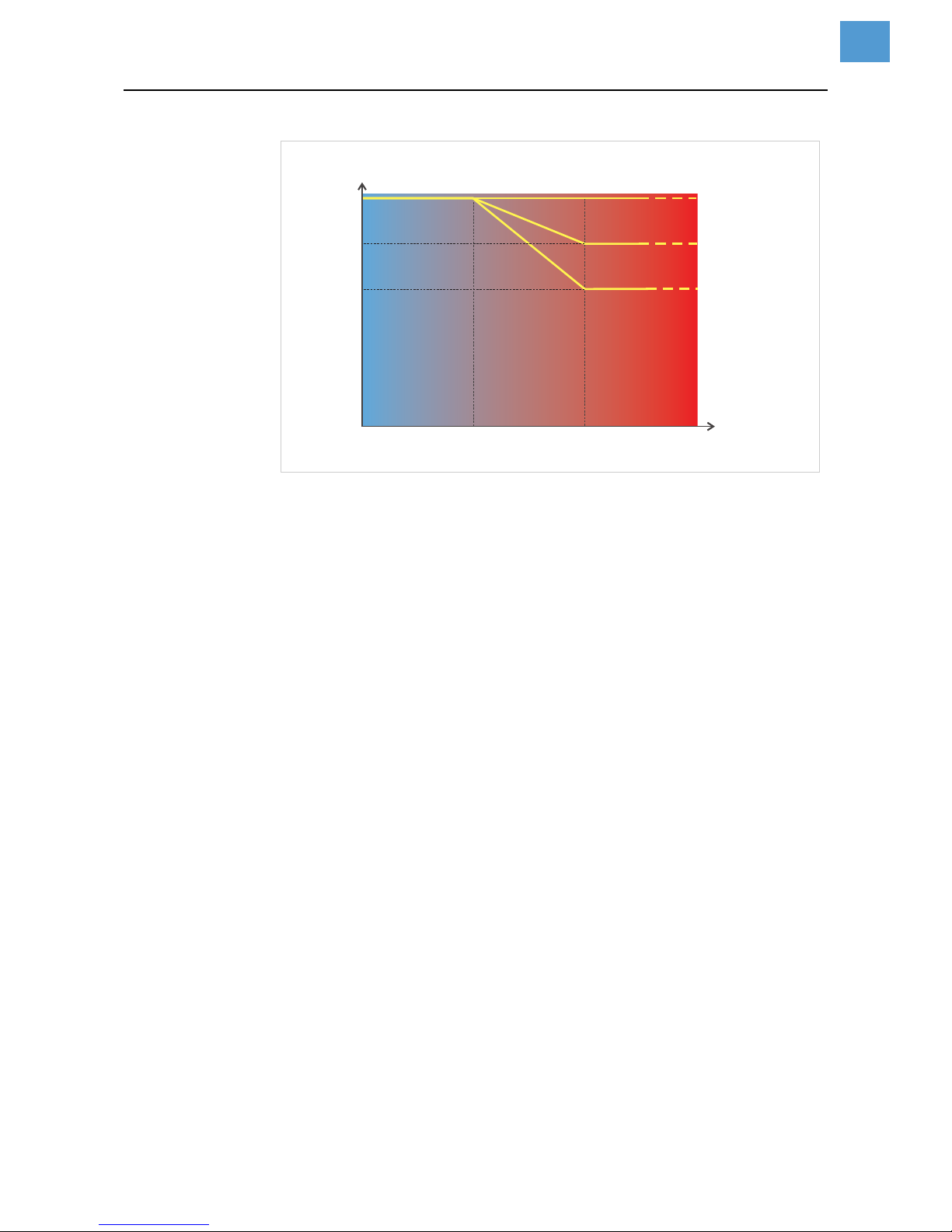
The temperature compensation is the greater, the higher the setting of the param-
eter SYSTEM PARAMETERS > Temp. reduction is [1].
Parameter Function
SYSTEM PARAMETERS >
Print contrast
Sets the print contrast, i.e. indirectly, the printhead temperature (actually adjusts the driving power of the printhead).
SYSTEM PARAMETERS >
Temp. reduction
Sets the correction factor for the temperature compensation. The higher the selected setting, the greater the reduction of the driving power when the printhead
temperature rises.
[Tab. 1] Parameters for setting the temperature compensation.
Page 42
11/14 Rev. 03 USER MANUAL Advanced Applications
AP 4.4 – AP 5.4 – AP 5.6 – AP 7.t – 64-xx – DPM – PEM – ALX 92x
3
[1] With the parameter SYSTEM PARAMETERS > Temp. reduction activated, the driving power of the printhead
– and therefore indirectly the print contrast – are reduced. Reduction starts at a temperature of 26°C.
The maximum value is maintained at 54°C and above.
Readout example The driving power of the printhead is 100% (setable in online mode after pressing the
Prog button).
The printing layout contains a lot of black areas. For this reason, the temperature reduction is activated with 40%.
SYSTEM PARAMETERS > Temp. reduction = 40%.
Now, if the printhead temperature rises above 26°C, the driving power will be reduced
automatically.
Reading out the diagram results in: With a given printhead temperature of approx.
40°C, the driving power is reduced to approx. 80%; with a supposed printhead temperature of 54°C or above, it is reduced to 60%.
26
54
°C
0
100
%
80
TR=0
TR=20%
TR=40%
60
Print head
temperature
Drive performance
print head
TR = “SYSTEM PARAMETERS / Temp. reduction”
Page 43

11/14 Rev. 03 USER MANUAL Advanced Applications
AP 4.4 – AP 5.4 – AP 5.6 – AP 7.t – 64-xx – DPM – PEM – ALX 92x
4
Printing with start signal
Application notes
Print-and-Apply systems are normally triggered by an external start signal, which typically comes from a product sensor placed at the conveyor. In most cases, after a start
signal arrived, a label is printed, dispensed and applied on the product.
This chapter describes…
• different ways of connecting a start signal source
• required settings in the printer parameter menu
Available interfaces
Depending on the printer type and configuration, different interfaces for start signal input are available (Tab. 2).
Printer
Singlestart
a
a) Singlestart connector on the devices rear side
USI
b
b) USI board with signal interface
AI
c
c) Applicator Interface with signal interface
E/A
d
d) I/O board with signal interface
64-xx Dispenser S O -- --
64-xx OO----
AP 5.4 Dispenser S -- -- O
AP 4.4 O -- -- --
AP 5.4 O -- -- O
AP 5.4 Gen. 2 S -- -- O
AP 5.6 S -- -- O
AP 7.t O -- -- O
ALX92x OOO--
[Tab. 2] Interfaces for start signal input for the different printer types
(S = Standard; O = Optional; -- = No option)
Page 44
11/14 Rev. 03 USER MANUAL Advanced Applications
AP 4.4 – AP 5.4 – AP 5.6 – AP 7.t – 64-xx – DPM – PEM – ALX 92x
5
Connecting the signal source
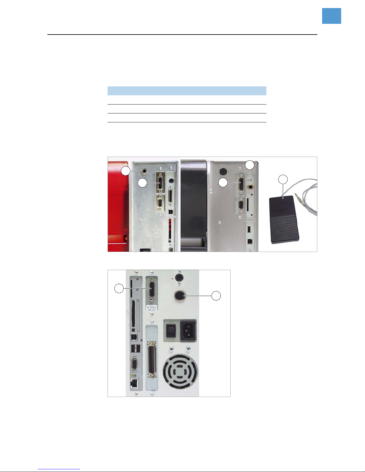
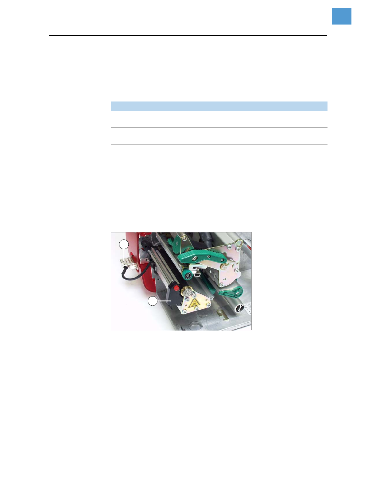
Footswitch Footswitches are available as accessory for both, 64-xx and AP 5.4/5.6 printers and
are shipped ready configured (see topic section Accessories ).
Connect the footswitch to the singlestart connector [2A].
[2] Single-start connector (A) and I/O board signal connector (B) at AP 5.4 (left) and at AP 5.4 Gen. 2 or
AP 5.6 (right) respectively. Matching footswitch (C) with 3-point plug.
[3] USI signal connector (A) and singlestart connector (B) at a 64-xx.
If the printer is operated with a LTSI applicator, the footswitch
has to be connected to the USI!
Printer Article no. foot switch
AP 5.4, AP5.4 Gen. 2, AP 5.6 A4053
64-xx Dispenser with LTSI A4053 + A7268
a
a) Adapter cable for connection to a USI.
64-xx Dispenser 97685
[Tab. 3] Article numbers for foot switches.
C
A
B
A
B
B
A
Page 45
11/14 Rev. 03 USER MANUAL Advanced Applications
AP 4.4 – AP 5.4 – AP 5.6 – AP 7.t – 64-xx – DPM – PEM – ALX 92x
6
USI, AI, E/A The 3 accessory boards USI, AI and I/O provide each a signal interface shaped as a
D-Sub connector [2B] [3A]. To those connectors, a start signal source can be connected.
The signal source has to be connected by a qualified service technician.
For detailed information on connecting a signal source see (Tab. 4):
Light barrier (64-xx Dispenser type M and AP 5.4/5.6 Dispenser only) This printer type is shipped
with a short dispensing edge [4B] with a light barrier, which serves as signal source.
After printing and dispensing, the label blocks the light barrier and stopps the printer
until the label is taken off. As soon as the light barrier is clear again, the next label is
printed.
Connect the light barrier to the D-Sub connector at the printer front side [4A].
[4] AP 5.4 Dispenser.
Board Cross-Reference
USI
Topic section „Electronics Gen. 3“, chapter „USI board“,
Circuit diagrams for signal inputs on page 30
AI
Topic section „Applicator Interface“, chapter „Interface description“,
Cir-
cuit diagrams for signal inputs
on page 21
I/O
Topic section „Service Electronics“, chapter „I/O board“,
Input/Output Signals on page 19
[Tab. 4] Topic sections with information about connecting the signal sources to be found in the service ma-
nual of the appropriate printer.
B
A
Page 46

11/14 Rev. 03 USER MANUAL Advanced Applications
AP 4.4 – AP 5.4 – AP 5.6 – AP 7.t – 64-xx – DPM – PEM – ALX 92x
7
Settings in the parameter menu
Further settings for 64-xx Dispenser see user manual 64-xx, topic section „Setup“,
chapter Settings at 64-xx dispensers on page 17.
Settings for application of ALX 92x with applicator see service manual ALX 92x,
topic section „Applicator Interface“, chapter
Selecting an applicator type on page 5.
Setting Interface Printer Parameter Value
Accept start signals
-- All
SYSTEM PARAMETER > External signal
Singlestart
Signal source
Singlestart
input
64-xx --
a
--
64-xx Dispenser,
AP 5.4 Dispenser,
AP 5.6 Dispenser
DISPENSER PARA > Start
source
Foot switch
AP 5.4, AP5.6, AP 7.t -- --
Disp. edge
light barrier
64-xx Dispenser,
AP 5.4Dispenser,
AP 5.6 Dispenser
DISPENSER PARA > Start
source
Light barrier
USI
64-xx Dispenser
DISPENSER PARA > Start
source
USI interface
64-xx, ALX 92x, ALX 73x -- --
I/O AP 5.4, AP 5.6, AP 7.t -- --
AI ALX 92x, ALX73x -- --
Signal flange
Singlestart
input
64-xx, AP 5.4, AP7.t,
AP 5.4Gen II, AP 5.6
SYSTEM PARAMETER > Start
print mode
„Pulse rising“
USI 64-xx, ALX 92x
DP INTERFACE > Start print
mode
„Pulse rising“
I/O AP 5.4, AP 5.6, AP 7.t
I/O BOARD >
Start print mode
„Pulse rising“
AI ALX 92x, ALX73x
APPLICATOR PARA > Start
print mode
„Pulse rising“
Start delay
Singlestart
input
AP 5.4Gen II Dispenser,
AP 5.6 Dispenser
DISPENSER PARA > Start Offset
Enter distance
between start
sensor and dispensing edge
USI 64-xx, ALX 92x, ALX 73x DP INTERFACE > Start delay
I/O
AP 5.4Gen II Dispenser,
AP 5.6 Dispenser
DISPENSER PARA > Start Offset
AI ALX 92x, ALX73x
APPLICATOR PARA > Start delay
[Tab. 5] Overview on the most important settings for start signal application (Firmware versions 3.52/6.52/7.52).
a) „--“ = No setting required.
Page 47
11/14 Rev. 03 USER MANUAL Advanced Applications
AP 4.4 – AP 5.4 – AP 5.6 – AP 7.t – 64-xx – DPM – PEM – ALX 92x
8
Standalone Operation
Requirements
Printer Suitable printers: all devices listed in the headline of this document, except for AP 4.4
(which has no card slot)
Firmware
CPU board
Options board
Is required for the printer types listed below to be able to connect a keyboard. The order number for the options board can be found in topic section Accessories .
• 64-xx Gen. 2
•DPM Gen. 2
• PEM Gen. 2
• ALX 92x Gen. 2
Memory card For order number, see the Plugin Card Manual, topic Available Cards .
Card reader PC or laptop with card reader
Printer Feature Firmware version
64-xx, DPM, PEM, ALX 92x Gen. 2
a
a) Characteristic feature: No USB interfaces, but Centronics as standard.
3.0
64-xx, DPM, PEM, ALX 92x Gen. 3
b
b) Characteristic feature: USB interfaces, Centronics optional.
5.02
ALX 73x -- 6.36
AP 5.4, AP7.t -- 1.10
AP 5.4 Gen II, AP5.6 MLK 3.34
[Tab. 6] Minimum firmware requirement for standalone operation.
Printer Feature CPU board number
64-xx, DPM, PEM, ALX 92x Gen. 2 A2292/ A2293
64-xx, DPM, PEM, ALX 92x Gen. 3 A6621
PM 3000 -- A6621
AP 5.4, AP7.t -- A3927
AP 5.4 Gen II, AP5.6 MLK A100150
[Tab. 7] Minimum CPU board requirement for standalone operation.
Page 48
11/14 Rev. 03 USER MANUAL Advanced Applications
AP 4.4 – AP 5.4 – AP 5.6 – AP 7.t – 64-xx – DPM – PEM – ALX 92x
9
Keyboard On request, a keyboard can be connected to the printer. This considerably simplifies
entry of variable data, especially when dealing with text.
64-xx, DPM, PEM and ALX 92x of Generation 2 require an additional board for
connecting the keyboard, see chapter Options board on page 8. The Options board
provides a PS/2 connector; an USB-to-PS/2 adapter comes with the offered keyboards.
The matching keyboard layout is set with parameter SYSTEM PARAMETER > keyboard.
Before first use, check if the intended keyboard really works with the printer.
Functional Description
Standalone operation means the printer can be operated without it needing to be connected to a host computer. For this purpose, a PC is used to store the print job on a
CompactFlash card (memory card). After this card is plugged into the card slot at the
printer, the operator can start the print jobs on demand. For this, he uses the printer
control panel or a keyboard connected to the printer. Variable data can also be entered
via the control panel or the external keyboard.
The standalone mode can always be accessed from the „normal“ printer operation
(with online/offline mode and message mode). To do so, press the Online and Esc buttons simultaneously.
It is helpfull to imagine two consoles, between which can be switched by pressing Online+Esc.
Keyboard type Order #
USB-keyboard
a
without numeric keypad, German layout
a) Comes with USB-to-PS/2 adapter (required for „AP 5.4 red“ and for „64-xx Gen. 2“)
A8407
USB-keyboard
a
without numeric keypad, US layout A8406
[Tab. 8] Keyboards available as accessory.
Console
„Normal operation“
Console
„Standalone operation“
Online mode
Online
+
Esc
Selecting print jobs
Offline mode Inserting field contents
Message mode Inserting print amounts
Parameter menu Starting print jobs
Error messages are faded in
[Tab. 9] Functions and display texts in normal and in standalone operation mode.
Page 49

11/14 Rev. 03 USER MANUAL Advanced Applications
AP 4.4 – AP 5.4 – AP 5.6 – AP 7.t – 64-xx – DPM – PEM – ALX 92x
10
Features Standalone operation in brief:
• Printing without computer connection
• Data entry via control panel or keyboard
• Reading print job from the memory card
• Entry or selection of field content
• Updating Firmware from memory card
Selecting files from memory card
Requirements The card slot which is used for standalone operation must provide the drive letter C.
64-xx, DPM, PEM, ALX 92x
1
:
Set INTERF.PARAM. > DRIVEASSIGNMENT > Drive C to „Compact flash“ or „Compact
flash 2 “ („Compact flash 2“ appears only with the optional 2
nd
card slot).
AP 5.4 Gen. 2, AP5.6:
Set INTERF.PARAM. > DRIVEASSIGNMENT > Drive C to „SD/MMC card“ (= factory set-
ting).
Other printers: No settng required
Selectable are files with the following extentions:
• „*.FOR“ (printjob)
• „*.S3B“ (firmware)
The files must be stored on memory card in folder \FORMATS.
If no file with one of the above listed endings is found in folder \FORMATS, or if no
memory card is inserted, the following message appears:
If a huge amount of printjob files is stored in folder \FORMATS, this can lead to the
following status message:
To remedy the cause of this message, take one (or both) of the following measures:
• Reduce the number of files in the \FORMATS folder
• Increase the amount of assigned memory in SYSTEM PARAMETER > Free store size
Selecting a file 1. Press the Online + Esc buttons to get into the standalone mode. The following is
displayed:
„Avery.for“ stands for any printjob file, which is stored in the \FORMATS folder.
Assumption: More than one file is stored in the \FORMATS folder: In this case the
first file in alphabetical order is displayed.
2. Press the Cut or Feed button to step to the next file.
Press the Esc button to jump back to the first entry of the list.
1) With firmware version 5.32 or higher (each Gen. 3)
Standalone
No files!
Status num: 8857
Wrong mem config
Choose a file
Avery.for
Page 50

11/14 Rev. 03 USER MANUAL Advanced Applications
AP 4.4 – AP 5.4 – AP 5.6 – AP 7.t – 64-xx – DPM – PEM – ALX 92x
11
3. Press the Online button to start proceeding the file
In case of a printjob file, the printjob is started, in case of a firmware file, the firmware upload starts.
The following message appears after selecting a printjob:
„Avery.for“ = printjob file
The point after „Executing“ moves as long as the interpreter works.
Afterwards, input data are requested. If no input fields are provided, only the print
amount is queried:
The initial print amount is set in the printjob.
4. Change the print
5. Press the buttons Online+Esc to get back to the Online mode.
Key/button functions
Quick selection
If an external keyboard is connected, the file can be selected by typing in the first
letter of the file name.
Example:
After changing to the standalone mode, the following is displayed:
„Avery.for“ stands for any printjob file, which is stored in the \FORMATS folder.
1. Press the key for the first letter of the wanted file name , e. g. „D“. Display:
D stands for the typed-in character.
„Default.for“ is in alphabetical order the first file with a „D“ as first letter.
2. Press the enter key to select the file, or
Press the esc key to undo the input.
Executing printjobs
All input fields are polled, which are defined as such in the print job (see Example Ap-
plication on page 14). Next, the print quantity is requested. As soon as the print
quantity is confirmed (online button), the print job is executed. From now on, all infor-
Avery.for
Executing .
Enter quantity
1
Operation Printer button Keyboard key
Go to previous file Feed Cursor Up
Go to next file Cut (or Apply) Cursor Down
Confirm the selection Online Enter
More than one file: jump back to
the first file in the list
Esc Esc
[Tab. 10] Keys for file selection
Choose a file
Avery.for
D
Default.for
Page 51

11/14 Rev. 03 USER MANUAL Advanced Applications
AP 4.4 – AP 5.4 – AP 5.6 – AP 7.t – 64-xx – DPM – PEM – ALX 92x
12
mation about the job is displayed in the "Print control" console. While the print job is
processed, it is started newly in the „Standalone“ console. The input fields are polled
again, with the previous entries as default. Alternating with the first input field, the text
„Start next job“ is diplayed.
Each printjob file may contain only one printjob. If any printjob file contains more
than one printjobs, only the first printjob is executed.
The new start of the print job can be avoided by setting the parameter SYSTEM PA-
RAMETER > Single job mode to „deactivated“.
Press the Esc button to go back to the file selection.
It's also possible to enter a single „* “ for the print quantity. This makes the print
quantity „endless“.
Operation Printer button Keyboard key
Increase by 1 Feed Cursor Up
Decrease by 1
(the predecessor of 0 is 9)
Cut (or Apply) Cursor Down
Enter Online Enter
Delete/Cancel Esc Esc
[Tab. 11] Keys for entering variable data
Page 52
11/14 Rev. 03 USER MANUAL Advanced Applications
AP 4.4 – AP 5.4 – AP 5.6 – AP 7.t – 64-xx – DPM – PEM – ALX 92x
13
Executing firmware files
Files with the extension .S3B are firmware files. Selecting a firmware file means starting a firmware download. As this is a fundamental intervention to the system, firmware
files are not executed immediately. The query "Firmwaredownload ? No/Yes" demands explicit confirmation of the operator.
The same firmware file remamed to the extension .FOR is executed without que-
rying.
Automatic file execution
If the file DEFAULT.FOR (All letters lower case or all upper case; „Default.for“ doesn´t
work) exists on memory card in the folder \FORMATS, this file is executed automatically at system start. Display during power up, until the file is executed:
If a file \AUTOSTRT.FOR is also existing (in the root directory, not case-sensitive),
it will be executed first. But be aware that standalone-printjobs are only executed properly, if the relevant file is stored in \FORMATS, as described above.
Additionally usable keys on a keyboard
With an external keyboard connected, the printer can be operated without touching the
buttons of the operation panel. The function keys F5-F8 can be used alternatively to
the operation panel buttons:
Operation Printer button Keyboard key
Switch between Yes/No Feed Cursor Up
Switch between Yes/No Cut (or Apply) Cursor Down
Confirm the selection Online Enter
More than one file: jump back to the
first file in the list
Esc Esc
[Tab. 12] Keys for loading firmware files
Standalone
Initializing
Operation Keyboard key
Delete the current print job (works in both consoles) Ctrl+Del
Jump to the start (e.g. start of a file selection list) Ctrl+Home
Jump to the end (e.g. end of a file selection list) Ctrl+End
Change between Standalone and standard console Ctrl+Ins
Delete backwards Backspace
Same function as printer button F5
Same function as printer button F6
Same function as printer button F7
Same function as printer button F8
[Tab. 13] Additional keys for operating the printer with an external keyboard.
Page 53

11/14 Rev. 03 USER MANUAL Advanced Applications
AP 4.4 – AP 5.4 – AP 5.6 – AP 7.t – 64-xx – DPM – PEM – ALX 92x
14
Insert Input Field in Printjob
Input fields can be defined in the following Easy Plug field types:
• Text field
• Counting field
• Barcode field
These field types can be defined through the following Easy Plug commands: YT, YN,
YB, IDM, PDF, MXC, CBF, YC, YS, YG.
Using a special syntax it is made clear in these commands that the text dealt with here
is not a fixed text, but text requested at the time of implementation.
Further information on the input field syntax can be found in the description of the respective command in the Easy Plug Manual, topic section Description of commands
.
Example Application
1. Generate two text files with the content shown in the tables below.
Tip: Cut out the content using the Acrobat Reader text selection tool and copy
it to a text file.
2. Create a directory on the memory card called \FORMATS.
3. Store the two text files as TEST1.FOR and AVERY.FOR on the memo ry c ard in the
directory \FORMATS.
The file ending must be *.FOR!
There is no difference made between uppercase and lowercase letters!
4. Switch off printer.
5. Insert memory card into the printer’s card slot.
6. Turn on printer and switch to online mode.
Example
#!A1#IMN100/60#ER
#J40#T5#YT107/0///Simple test for
#J30#T5#YN100/0/60///STANDALONE Mode
#Q3/
[Tab. 14] File „TEST1.FOR“
Example
#J10#T5#YT107/0///Fixtext#G
#J40#T5#YN100/0/60///$<Color:>,Lightred
#J40#T5#YN100/0/60///$<Color:>,Lightred
#J20#T5#YT107/0///$<Article number:>,
#!A1#IMN100/60#ER
#Q3/
[Tab. 15] File „AVERY.FOR“
Page 54

11/14 Rev. 03 USER MANUAL Advanced Applications
AP 4.4 – AP 5.4 – AP 5.6 – AP 7.t – 64-xx – DPM – PEM – ALX 92x
15
7. Simultaneously press the Online and ESC keys.
The first file on the memory card is displayed:
8. Call up the file TEST1.FOR by pressing the Cut or Feed keys.
On DPM or ALX 92x , please press the Apply instead of the Cut key!
9. Confirm selection by pressing the Online button.
Now you are asked for the quantity of labels to be printed:
Quantity 3 appears as default, as this was already preset in the printjob. To increase the quantity to 10, for instance, please perform the following procedure:
10. Press the ESC key. This erases the 3.
11. Press the Feed button in order to incrementally increase (up to a max. of 9) the
quantity of labels to be printed.
Quantity 0 = infinite printing!
12. Press the Online button to move forward by one position. Should you wish to enter
a number with two or more digits, simply increase the second digit using the Feed
button. Should the number only have one digit, press the Online button again.
The printer will now print the stipulated number of labels.
AVERY.FOR In case of the AVERY.FOR file, this works somewhat differently. Once the file is called
up, the following is displayed:
In the second line the printer will ask for the content for the first data field. “Color” is a
prompt and therefore not printed. The preset content of the printjob is called “Lightred”.
• Without keyboard you can enter the desired text in characters. Entering letters
works in the same way as digit entry (see example TEST1.FOR). Using the Cut or
Feed buttons, you can scroll through the available set of characters until the required character appears. Use the Online button to move forward by one position.
After entering the last character, press the Online button twice.
• With a keyboard you can, after the input prompt “Color:”, simply enter a different
content.
The entry may only have a length that ensures the printout does not extend over
the label edge! - otherwise a printer error message is displayed!
The next input field is displayed and then the next etc., until all input fields have been
processed.
At the end you may change the quantity of labels to be printed if required.
Choose a file
AVERY .FOR
Enter quantity
3
ONLINE 1 JOBS
Color: Lightred
Page 55

11/14 Rev. 03 USER MANUAL Advanced Applications
AP 4.4 – AP 5.4 – AP 5.6 – AP 7.t – 64-xx – DPM – PEM – ALX 92x
16
Data input by interface
Available with firmware x.33 or a later version.
Apart from putting in data by operation panel or by external keyboard, the data can be
sent via interface.
Application example: Reading in data from a RS232 barcode scanner via serial interface.
Selecting the interface INTERF.PARAM. > OPTIONS > StandAlone Input
Listed are only interfaces, which are available in the printer and are not already oc-
cupied by another function.
Application notes The following characters or character sequences are replaced by respectively one
„Enter“ action, if received.
• <CR>
1
• <CR><LF>
•<LF>
2
• <LF><CR>
Data received at the interface are processed only then, if the printer is switched to
standalone operation.
Example Example of a standalone printjob on the memory card:
#!A1#DC
#IMSR100.08/100.08
#HV50
#PR8/8/
#RX0
#ERN/1//0
#R0/0
#VTS/Var1//10///Test Var1#G
#VTS/Var2//10///Test Var2#G
#T34.16 #J90.75 #FD/0/L #SS100/BVUN/42X42/0 #VW/L/Var1#G
#T34.08 #J79.58 #FD/0/L #SS100/BVUN/42X42/0 #VW/L/Var2#G
#Q1#G
#!P1
The following data is received via the data interface:
Content1<cr><lf>
Content2<cr><lf>
3<cr><lf>
The first two lines assign the content „Content1“ to the variable „Var1“ and the content
„Content2“ to the variable „Var2“. The third line assigns the print quantity „3“.
1) <cr> = 0x0D
2) <lf> = 0x0A
Page 56
11/14 Rev. 03 USER MANUAL Advanced Applications
AP 4.4 – AP 5.4 – AP 5.6 – AP 7.t – 64-xx – DPM – PEM – ALX 92x
17
Data Transmission with Ethernet
System Requirements
Hardware • Printer
• Ethernet cable: must have quality „Cat. 5E“ and be shielded.
Software • Firmware:
• Network protocol: TCP/IP
CAUTION! - Unqualified manipulations of a data network can disturb or stop its proper functioning.
Connecting a device to a network requires network administrator knowledge.
Consult your network administrator for assistance, if you don´t have knowledge on
this level!
Printer Feature Ethernet connection by
AP 4.4 – Ethernet connection not possible!
AP 5.4 –
Integrated Ethernet interfaceAP 5.6 –
AP 7.t –
64-xx
Gen. 2
CPU board A2292 with integrated Ethernet interface (optional)
DPM
PEM
ALX 92x
64-xx
Gen. 3 Integrated Ethernet interface
DPM
PEM
ALX 92x
ALX 73x – Integrated Ethernet interface
[Tab. 16] Equipment of the different printer types witih Ethernet interfaces.
Printer Feature Firmware version
64-xx, DPM, PEM, ALX 92x Gen. 2 3.0
64-xx, DPM, PEM, ALX 92x Gen. 3 5.02
ALX 73x -- 6.36
a
a) Printer firmware
AP 5.4, AP5.6, AP 7.t -- alle Versionen
[Tab. 17] Minimum firmware requirement if it is to apply the Ethernet function.
Page 57
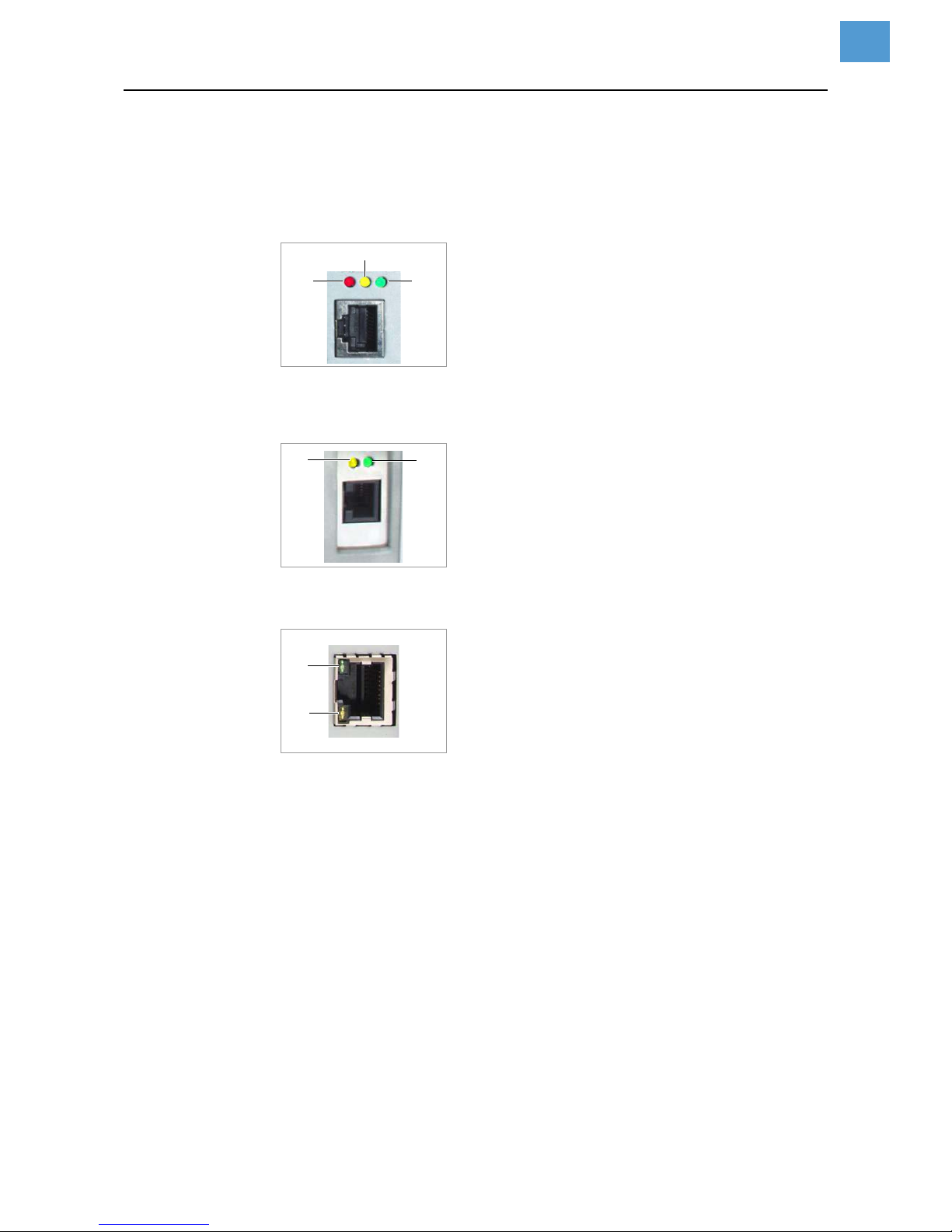
11/14 Rev. 03 USER MANUAL Advanced Applications
AP 4.4 – AP 5.4 – AP 5.6 – AP 7.t – 64-xx – DPM – PEM – ALX 92x
18
Integration of Ethernet Interface
The Ethernet interface of the printers is layed out as 10/100 Base T. The transmission
speed is set by autonegotiation. LEDs are located above the RJ45 plug, showing the
network situation [5][6][7].
[5] Position of the signal LEDs at 64-xx, DPM, PEM, ALX 92x (each Gen. 2).
A LED red lights = Printer is connected to network
B LED yellow flashes = Network traffic
C LED green lights = High transmission rate (100Mbit/s)
[6] Position of the signal LEDs at AP 5.4, AP 7.t, ALX 73x and 64-xx, DPM, PEM, ALX92x (each Gen. 3)
A LED yellow lights = Printer is connected to network; LED flashes =Network traffic
B LED green lights = High transmission rate (100Mbit/s)
[7] Position of the signal LEDs at AP 5.4 Gen. II and AP 5.6.
A LED yellow lights = Printer is connected to network; LED flashes =Network traffic
B LED green lights = High transmission rate (100Mbit/s)
MAC Address An internationally unique MAC (Media Access Control) address is required for Ether-
net operation. It consists of 6 bytes and is usually separated by colons or hyphens
(hexadecimal, e.g. 00:0a:44:02:00:49 or 00-0a-44-02-00-49). The first 3 bytes are
constant 00:0A:44 (Avery code), the last 3 bytes vary for each device. The product
manufacturer is responsible for the allocation of the MAC addresses.
IP Address In the printer software a TCP/IP protocol stack is implemented, i.e. for network purpos-
es the device requires an IP address along with the MAC address. IP-addresses are
always displayed as 4 bytes separated by dots (e.g. 192.168.1.99). IP addresses are
assigned by the network operator, as a rule the network administrator.
MAC and IP addresses originate from different protocol layers and are generally
independent of each other.
Further information about TCP/IP can be found in the abundance of literature on the
subject.
A
B
C
A
B
B
A
Page 58

11/14 Rev. 03 USER MANUAL Advanced Applications
AP 4.4 – AP 5.4 – AP 5.6 – AP 7.t – 64-xx – DPM – PEM – ALX 92x
19
Setting the IP Parameters
The IP-parameter settings can either be set fix, or they can be requested from a DHCP
server with every start of the printer. To assist the system administrator, the DHCP
server is provided a device name on request, which consists of a combination of printer type + 3 digits from the MAC address. (e.g. AP_5.4___300dpi_020049). The following values have been preset:
• IP address: 192.168.1.99
• Net mask: 255.255.255.0
• Default gateway: 0.0.0.0
Connection to a name server is not required.
WARNING: The address allocation for each device must be clear and unambigu-
ous. Ask your network administrator for assistance!
Transmission with Raw Socket Interface
Printing data can be transmitted using a parameterisable socket interface (TCP server
socket on port number > 1024).
This protocol is supported by
• all Unix derivatives; a connection similar to that of terminal servers can be established.
• Windows 2000, Windows XP
A software package from external providers is required for Windows 95, Windows
98 and Windows NT (e.g. Serial/IP by Tactical Software,
http://www.tacticalsoftware.com).
In this way you can set the Port address in the printer’s parameter menu:
Menu Parameter Description
INTERF. PARAM. >
NETWORK PARAM
IP addressassign
Here, please set “fixed IP address” or “DHCP”.
IP address
Net mask
Gateway address
IP parameter input fields, in case “fixed IP
address” was set for the address assign type.
[Tab. 18] Setting the IP parameters in the printer menu
Parameter Description
INTERF. PARAM. > NETWORK PARAM. > Port
address
Here you can select the port number
of the service in section 1024-65535
INTERF. PARAM. > EASYPLUGINTERPR > Interface
Here a TCP/IP socket must be set in
order to receive printing data at the
set port number.
[Tab. 19] Setting the port address in the printer´s parameter menu
Page 59
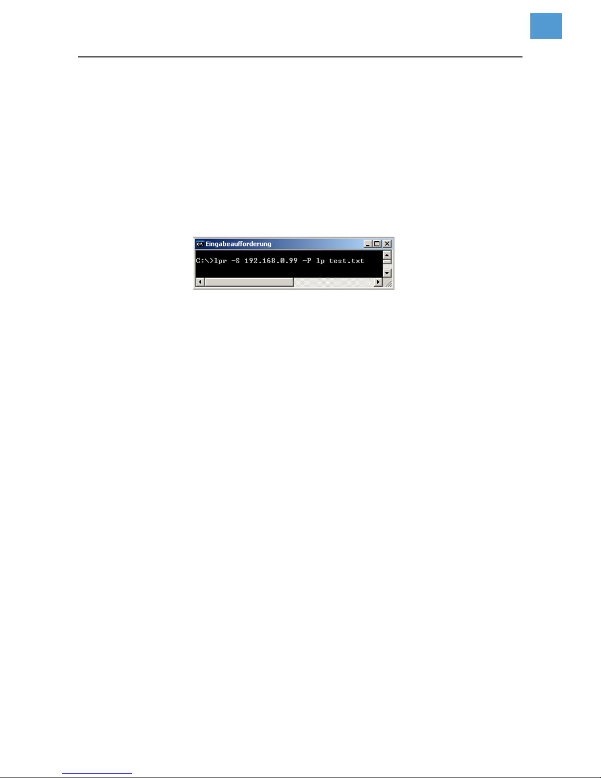
11/14 Rev. 03 USER MANUAL Advanced Applications
AP 4.4 – AP 5.4 – AP 5.6 – AP 7.t – 64-xx – DPM – PEM – ALX 92x
20
Transmission with LPD Server
Printing data can be transmitted to the printer using the LPR/LPD (Line Printer Daemon) protocol (“BSD Spooler”).
This protocol is supported by
• all Unix derivatives
• Windows NT, Windows 2000 und Windows XP
The print queue of the host must be named „lp“!
Example 1. Set parameter INTERF.PARAM. > EASYPLUGINTERPR > Interface to „LPD server“.
2. Send the printjob file (here: „test.txt“) as illustrated using the „lpr“ command [8].
[8] Sending a printjob with the „lpr“ command.
Enter „lpr ?“ to get a list of the admissible command options.
For the use of LPD server under Windows NT or Windows 2000, please refer
to the following link:
http://support.microsoft.com/default.aspx?scid=kb;EN-US;179156
For the use of LPD server under Windows 95 and Windows 98, a software
package from external providers is required (e.g. Windows LPR Spooler, see the
following link).
http://home.arcor.de/Heil-Consulting/
Troubleshooting
The following should be checked if a problem occurs:
• Ethernet connection: The yellow LED belonging to the printer network socket must
be illuminated. If this is not the case, possible sources of error are:
– that the network is not connected to the outlet.
– ISDN outlet: Erroneous, the network cable was connected to an ISDN instead
of a network outlet. Both outlet types do not differ mechanically.
– an incorrect cable (ISDN cable?) is used to connect the printer to the network
outlet.
– a defective hub/switch.
– a defective printer board.
• IP parameter: The defined parameters or parameters set via DHCP are displayed
in the “Printer Status” printout. A “ping” to the set IP address must return an echo.
This also works if a different interface is set in the Easy Plug Interpreter parameter.
Possible source of error: Incorrect configuration of a network participant.
• On the printer, either “TCP/IP socket” or “LPD server” must be set in the Easy Plug
Interpreter parameter.
Page 60

11/14 Rev. 03 USER MANUAL Advanced Applications
AP 4.4 – AP 5.4 – AP 5.6 – AP 7.t – 64-xx – DPM – PEM – ALX 92x
21
Access via Web/FTP server
Web server
Applications The web server makes it possible
• to set or read the values of parameters from the parameter menu via a web
browser
• to control the operator panel of the labeller resp. the printer via a web browser.
The web server is not multi-session compatible, i.e. only one user can be logged
in at any time.
The web server is a setup utility, not an operational one. The web server should
not be heavily used during a high performance application of the dispenser, otherwise
this could result in losses in machine performance.
Prerequisites • Suitable printers: All printers listed in the headline, apart from the AP 4.4
• Required firmware:
• The printer is connected to a network
• A valid IP address is assigned to the printer (by the network administrator or by a
DHCP server)
• INTERFACE PARA >NETWORK PARAM. > WEB server must be set to “On”.
Starting the web server 1. Note down the IP address of the printer.
This is shown under INTERFACE PARA >NETWORK PARAM. > IP address
2. Start the internet browser.
3. Enter the following in the address bar:
http://[IP address without initial zeroes]
Example: IP address = 144.093.029.031
Enter: http://144.93.29.31
Printer Feature Min. firmware vers.
64-xx, DPM, PEM, ALX 92x Gen. 2 3.40
64-xx, DPM, PEM, ALX 92x Gen. 3 5.02
AP 5.4, AP7.t -- 3.0
AP 5.4 Gen II, AP5.6 MLK 3.34
Page 61
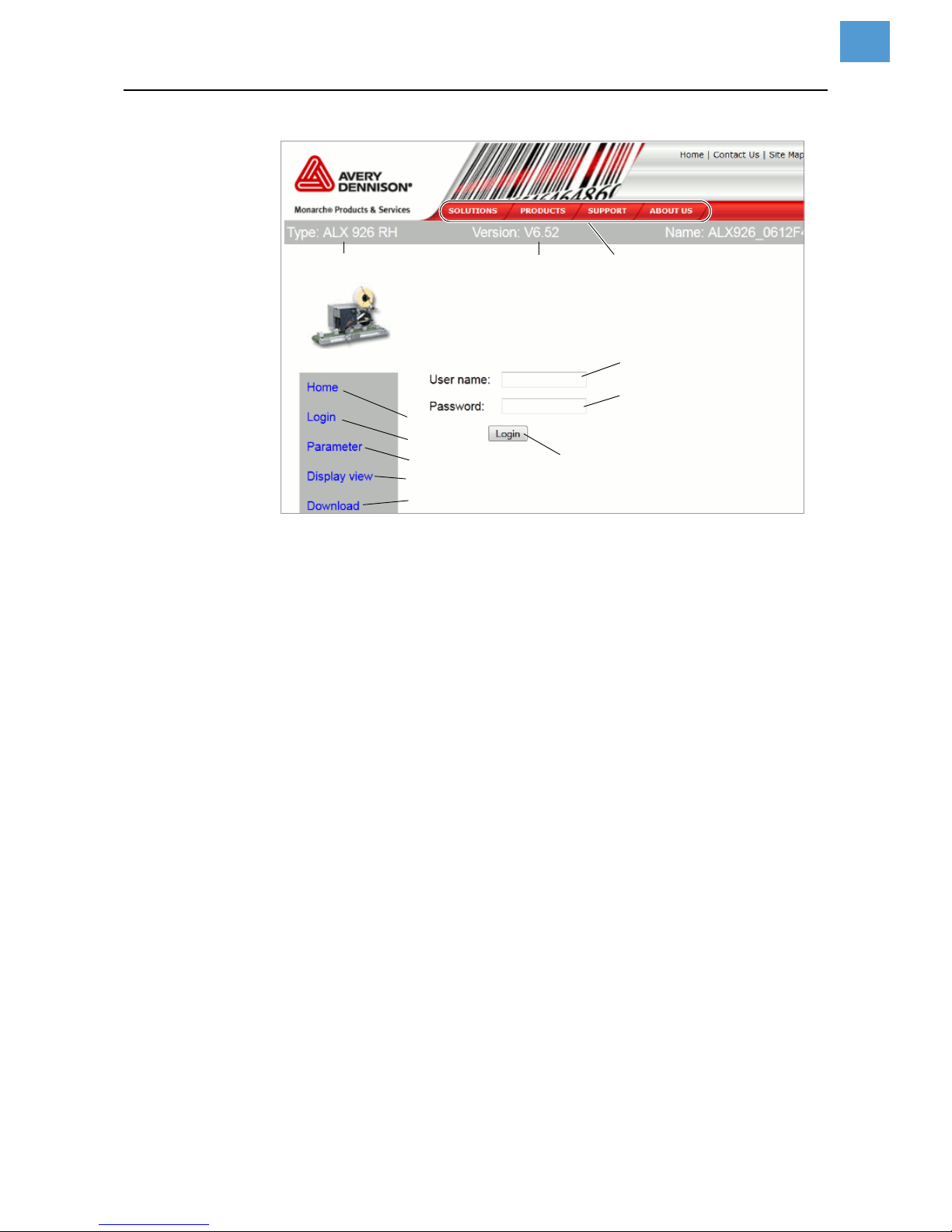
11/14 Rev. 03 USER MANUAL Advanced Applications
AP 4.4 – AP 5.4 – AP 5.6 – AP 7.t – 64-xx – DPM – PEM – ALX 92x
22
[9] Login dialogue of the web server
A Link to the web server home
B Opens input fields for user name and password [9]
C Calls the parameter menu
Enables settings in the labeller parameter menu to be changed.
D Calls the operator panel display
Gives access to all the parameters of the real operator panel
E Starts the FTP server in a new browser window
See chapter FTP server on page 25.
F Input field for user name
Preset: “admin”
G Input field for password
Preset: “admin”
The password can be changed under INTERFACE PARA >NETWORK PARAM. > WEB
server
H Click on this button after entering user name and password
I Displays the machine model
J Displays the firmware version
K Links to the Avery Dennison Machinery website
Logging in to the web
server
1. Click on the “Login” link [9B]
2. Enter user name and password [9F, G]
Preset in both cases: admin
3. Click on the “Login” button [9H]
A
B
C
D
E
F
G
H
IJK
Page 62
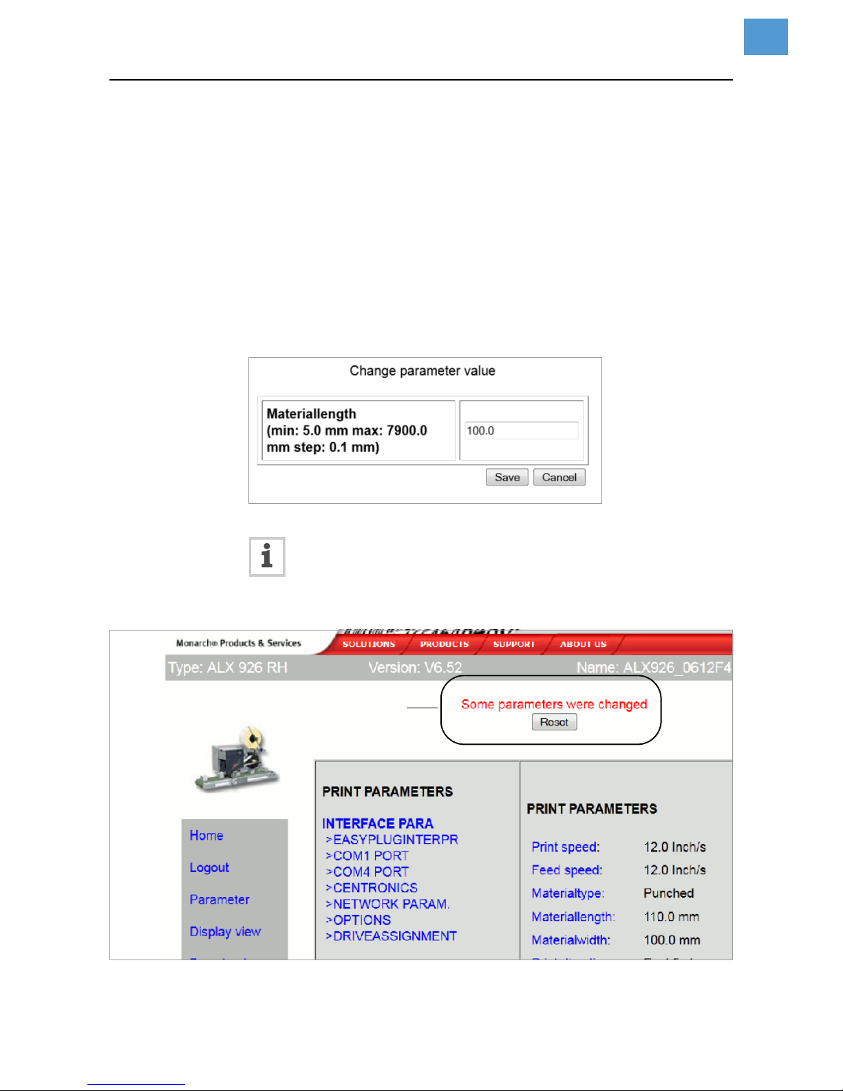
11/14 Rev. 03 USER MANUAL Advanced Applications
AP 4.4 – AP 5.4 – AP 5.6 – AP 7.t – 64-xx – DPM – PEM – ALX 92x
23
Changing a setting in
the labeller menu
Click on the names of submenus and parameters to open them so that you can
change the settings they contain.
Example
Making a change to PRINT PARAMETERS > Materiallength:
1. Click on “Parameter” link [9C].
2. Click on “PRINT PARAMETERS” link.
3. Click on “Materiallength” link.
4. A dialog box opens: [10].
5. Enter the required value in the entry field.
6. Click on the “Save” button.
The value is now transferred to the labeller.
[10] Example: Dialog box for entering value for the parameter PRINT PARAMETERS > Materiallength
Some parameters trigger a reset of the labeller, if they have been changed on
the labeller via the operator panel. However, if any of these parameters is
changed via the web server, the reset does not occur automatically. The
changes only come into effect after the next time the labeller is reset. In these cases,
the “Reset” button [11A] appears after the setting has been changed.
[11] Information (A): Changes made to the parameter setting do not come into effect until after a reset.
A
Page 63
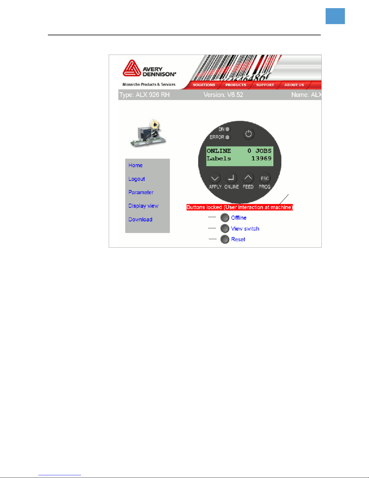
11/14 Rev. 03 USER MANUAL Advanced Applications
AP 4.4 – AP 5.4 – AP 5.6 – AP 7.t – 64-xx – DPM – PEM – ALX 92x
24
The virtual operator
panel
[12] The virtual operator panel
After the “Display view” link is clicked, an image of the operator panel (= virtual operator panel) appears on the screen [12]. All of the buttons on the real operator panel
can also be operated by mouse-click on the virtual operator panel.
The buttons [12A-C] underneath the virtual operator panel are equivalent to key combinations on the real operator panel
A “Offline” button
Sets the machine offline during dispensing mode
Equals pressing the ONLINE button
B “View switch” button
Switches into standalone mode
Equivalent to pressing the buttons ONLINE + ESC
C “Reset” button
Triggers a reset
Equivalent to pressing the buttons APPLY + ONLINE + FEED
D
A
B
C
Page 64

11/14 Rev. 03 USER MANUAL Advanced Applications
AP 4.4 – AP 5.4 – AP 5.6 – AP 7.t – 64-xx – DPM – PEM – ALX 92x
25
D Status line [13E]
In order to avoid putting an operating person at the machine at risk by sudden
starting up of the machine, the virtual operator panel is locked as soon as a button
at the machine operator panel is pressed. The status line indicates the current
status:
FTP server
Applications The file transfer protocol (FTP)server (RFC959) enables access to the internal RAM
disk and to the memory card in the card slot of the LMA/PMA (as long as there is a
memory card in the slot).
In this way, files (configuration or firmware files) can be saved to the memory card or
the internal RAM disk, or existing files renamed or deleted.
The FTP server is multi-session compatible.
The FTP server should not be heavily used during a high performance application
of the labeller.
Prerequisites • The printer is connected to a network
• A valid IP address is assigned to the printer (by the network administrator or by a
DHCP server)
• INTERFACE PARA >NETWORK PARAM. > FTP server is set to “On”.
• A FTP client
1
is installed on the host computer.
• The FTP connection is not blocked by a firewall
Establishing a FTP
connection
1. Note down the IP address of the printer.
The IP address is shown under INTERFACE PARA >NETWORK PARAM. > IP address
2. Start the FTP client.
3. Enter the following in the address bar:
ftp://[IP address without initial zeroes]
Example: IP address = 144.093.029.047
Enter: ftp://144.93.29.47
An input field for the user name and password appears.
Message Meaning
No
A user is logged in at the virtual operator panel. The virtual
operator panel is unlocked.
„Buttons locked
(not logged in)“
No user is logged in at the virtual operator panel. The virtual operator panel is locked.
„Buttons locked
(User interaction at
machine)“
A user is logged in at the virtual operator panel. The virtual
operator panel is blocked, because an operator at the machine operator panel has pressed a button
Reactivate the virtual operator panel:
Switch from „Offline“ to „Online“ at the machine opera-
tor panel.
1) e. g. WS-FTP, Internet Explorer, Midnight Commander, Firefox
Page 65
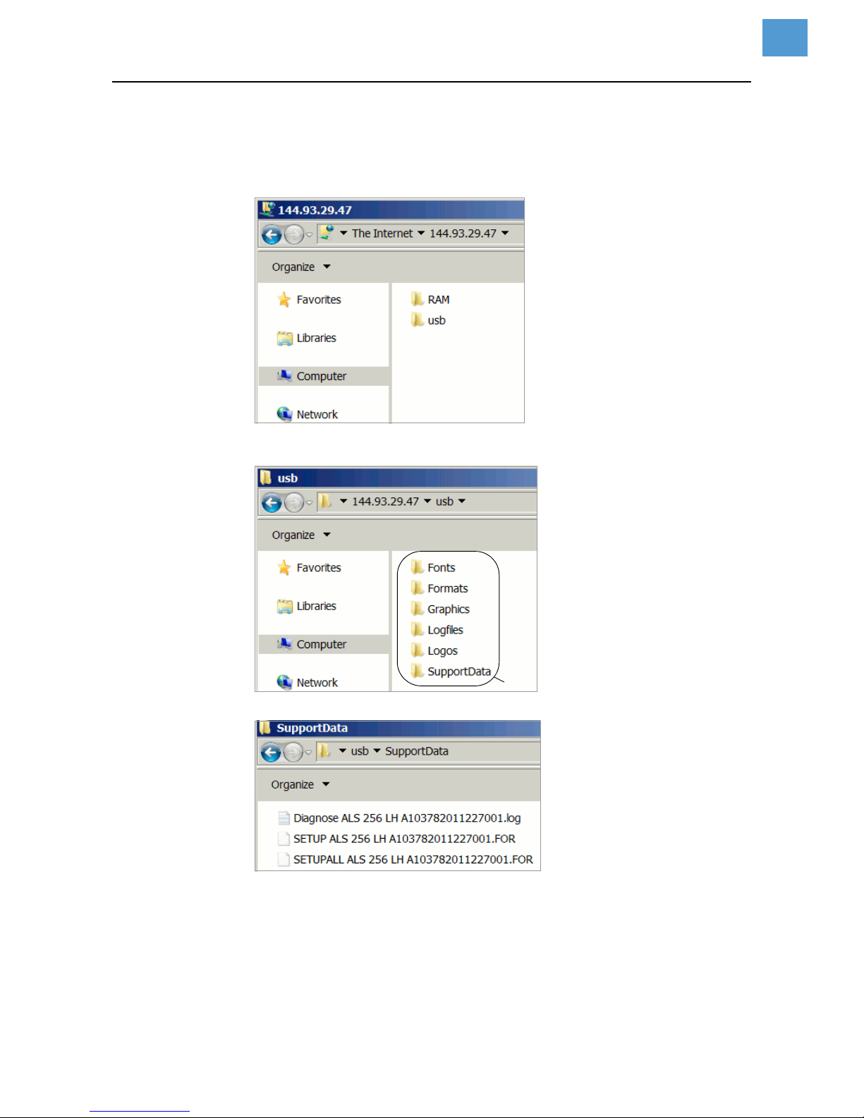
11/14 Rev. 03 USER MANUAL Advanced Applications
AP 4.4 – AP 5.4 – AP 5.6 – AP 7.t – 64-xx – DPM – PEM – ALX 92x
26
4. Enter user name and password.
A user name can be chosen at will; preset password = “avery”
Change the password under INTERFACE PARA >NETWORK PARAM. > FTP Password
[13] User interface of the FTP server in the Windows Explorer.
RAM = internal machine memory; usb = connected USB stick.
[14] Folders on the USB stick (A).
[15] Files in folder „SupportData“.
A
Page 66

11/14 Rev. 03 USER MANUAL Advanced Applications
AP 4.4 – AP 5.4 – AP 5.6 – AP 7.t – 64-xx – DPM – PEM – ALX 92x
27
If the login was successful, separate folders appear in the FTP client, one for the internal RAM disk and one for each connected memory medium [13]:
•RAM:
The content of the RAM disk is without matter for the user.
• USB:
If one of the functions for storing setup or diagnosis data on a memory medium
was already processed, the following subfolders can be found here
1
:
Subfolder Comment
Formats
• Location for setup files (see MASCHINEN SETUP >
Param. speichern)
• Location for firmware files to be uploaded in standalone mode
Logfiles
Location for diagnosis files (see SERVICE/DIAGNOS. >
Diagnose speich.)
SupportData
Location for setup and diagnosis files (see SERVICE/
DIAGNOS. > Gen.SupportDaten) [15]
Fonts
Without functionGraphics
Logos
1) Depending on the applied memory medium appears SD, CF or USB.
Page 67
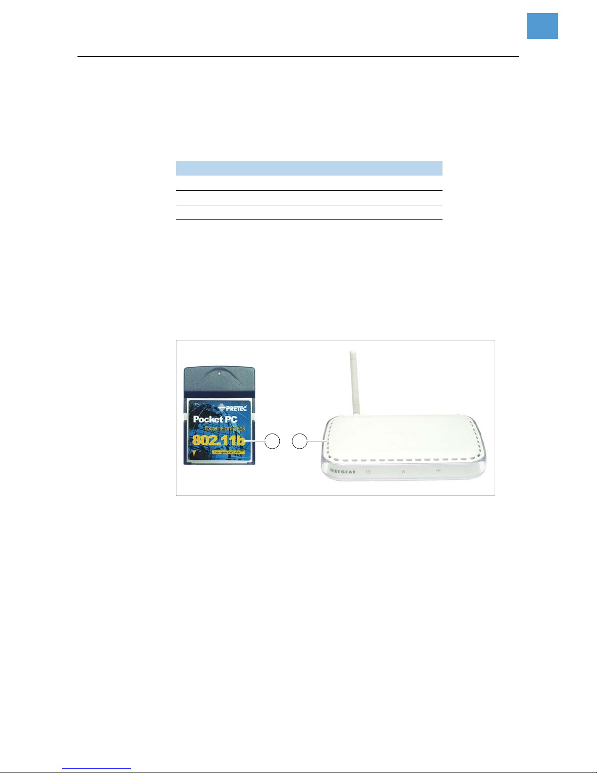
11/14 Rev. 03 USER MANUAL Advanced Applications
AP 4.4 – AP 5.4 – AP 5.6 – AP 7.t – 64-xx – DPM – PEM – ALX 92x
28
Data transmission with WLAN
According to standard IEEE 802.11b
Requirements
Suitable printers
Revision number
CPU board
• AP 5.4, AP 7.t: at least 3 (A3927-03)
• 64-xx, DPM, PEM, ALX 92x, ALX 73x: at least 4 (A6621-04)
Displaying the revision number: SERVICE DATA > CPU BOARD DATA > CPU identifier
WLAN CF cards • D-Link „DCF-660W“ (article number A7456)
• Linksys „WCF12“ (no longer availabe)
• Pretec „OC-WLBXX-A“ (no longer availabe) [16A]
[16] WLAN CF card (A) ; Wireless Access Point (B)
Further requirements • Access point according to standard IEEE 802.11b station mode „infrastructure“ (e.
g. „Netgear Wireless Access Point WG602“ [16B])
• Ethernet crossed link cable (1:1 cable), to connect the access point to the host
computer
• PC with operating system Windows XP
Notes
WLAN = Wireless Local Area Network
This section describes a simple setup, with which data transmission from a host computer (e. g. PC) via an access point to a label printer can be testet. This setup doesn´t
suit for real network operation.
Printer Firmware
AP 5.4, AP7.t 3.00
64-xx, DPM, PEM, ALX 92x (each Gen. 3) 5.31
ALX 73x 6.36
[Tab. 20] Minimum firmware versions for use of WLAN.
A B
Page 68
11/14 Rev. 03 USER MANUAL Advanced Applications
AP 4.4 – AP 5.4 – AP 5.6 – AP 7.t – 64-xx – DPM – PEM – ALX 92x
29
Printer setup
1. Insert the WLAN CF card into the printers card slot. Switch the printer on.
In the printer menu INTERF. PARAM. > NETWORK PARAM., additional parameters for
WLAN operation show up.
The LED at the card is flashing as long as the card is not logged in at the access
point.
2. Make the following settings in the INTERF. PARAM. > NETWORK PARAM. menu:
3. Set parameter INTERF. PARAM. > EASYPLUGINTERPR > Interface to „LPD Server“.
4. Restart printer to activate the settings.
Connecting
1. Connect the access point to the PC using a crossed link cable. Connect the access point to the mains supply and switch it on.
2. Check, if the LED at the WLAN CF card lights up permanent. If it does not, check
the following points:
– Is the card plugged firmly into the card slot?
– Does the card match one of the supported card types?
– Is the parameter INTERF. PARAM. > NETWORK PARAM. > WLAN SSID set to „idt“
(small letters!)?
CAUTION! - Network manipulations can disturb or avoid proper network operation.
Before connecting any device to a network, always ensure the approval of the net-
work administrator.
Parameter Setting Note
IP addressassign Fixed IP address
IP address
e. g.
192.168.000.999
ask the network administrator for it;
the initial three bytes must equal
the PC address
Net mask 255.255.255.000 = default setting
WLAN SSID idt use lower case letters
WLAN WEP disabled
WLAN default key 0 or any other setting
FTP server arbitrary setting
WEB Server arbitrary setting
[Tab. 21] Required parameter settings in the printer menu.
Page 69
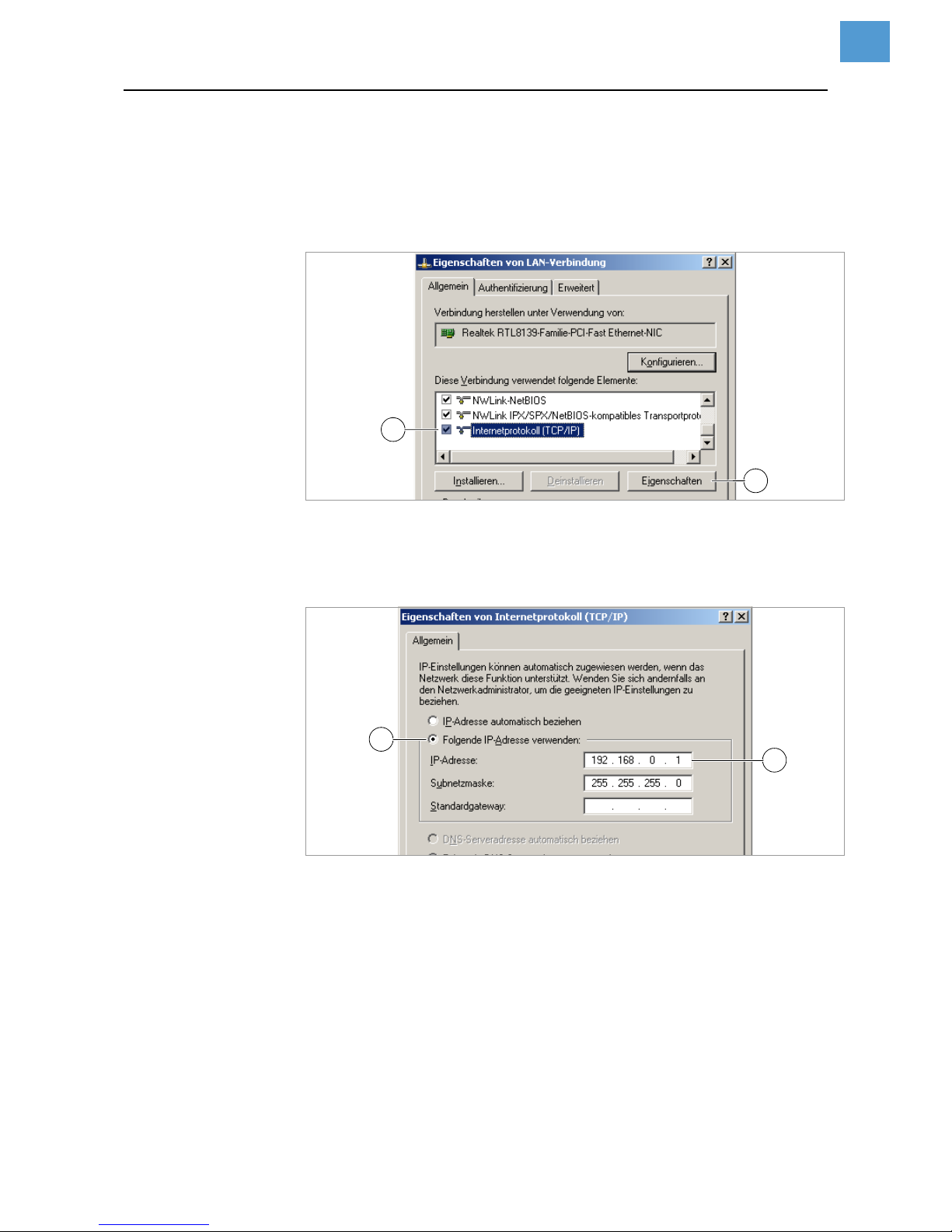
11/14 Rev. 03 USER MANUAL Advanced Applications
AP 4.4 – AP 5.4 – AP 5.6 – AP 7.t – 64-xx – DPM – PEM – ALX 92x
30
PC setup
1. In Windows XP call: Start > Settings > System > Network.
2. Click on Configuration, click the right mouse button and select Properties.
Window [17] shows up.
[17] „Properties of LAN connection“ window.
3. Select the item „Internet protocol (TCP/IP)“ [17A] and click on the „Properties“ button [17B].
Window [18] appears.
[18] „Properties of internet protocol (TCP/IP)“ window.
4. Activate the input field for fixed IP addresses [18A].
5. Ask the network administrator for suitable IP addresses. Type the IP address into
field [18B] (e. g. 192.168.0.1).
6. Restart the PC to activate the settings.
A
B
B
A
Page 70
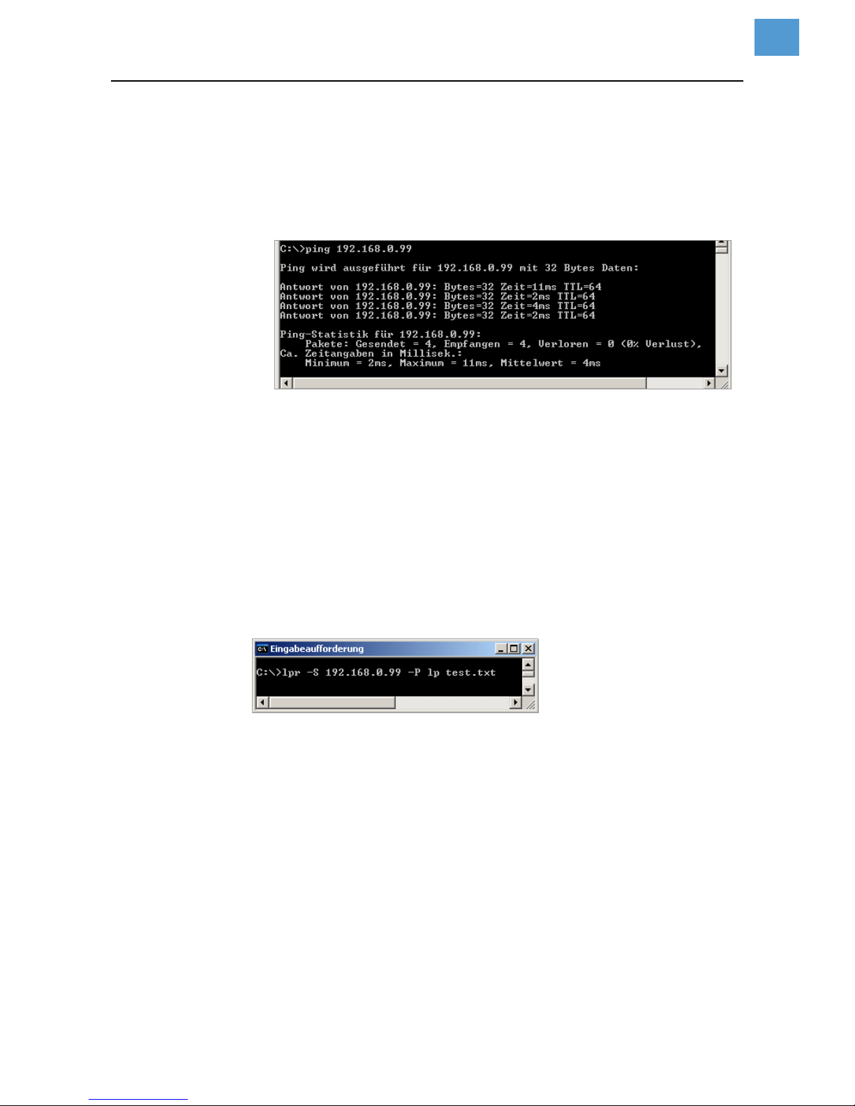
11/14 Rev. 03 USER MANUAL Advanced Applications
AP 4.4 – AP 5.4 – AP 5.6 – AP 7.t – 64-xx – DPM – PEM – ALX 92x
31
Testing the connection
1. Call the input window: Start > Programs > Accessories > Input prompt.
2. Enter the command „ping“ with the printers IP address, e.g. „ping 192.168.0.99“.
3. If the connection works properly, four answer lines appear in the input prompt window [19].
[19] Input prompt window after proceeding ping with the printers IP address.
As an additional test, „ping“ can also be called with the IP address of the access
point. The default IP address of the Netgear WG602 is 192.168.0.227
If the printer doesn´t send back an answer, the connection doesn´t work properly.
Measures in this case are:
Check all the above mentioned settings.
Contact the network administrator for advice.
Sending a printjob
1. Have an Easy-Plug printjob ready (in this example: „test.txt“).
2. Send the printjob using the command „lpr“ [20].
[20] Sending a printjob using the lpr command
After some seconds, the printer should start printing.
During data transmission, the LED at the WLAN CF card flashes.
Page 71
11/14 Rev. 03 USER MANUAL Advanced Applications
AP 4.4 – AP 5.4 – AP 5.6 – AP 7.t – 64-xx – DPM – PEM – ALX 92x
32
Storing and transferring parameter settings
Recommendations
• Suitable printers: All printers listed in the headline, apart from the AP 4.4 (which
has no card slot)
• Firmware:
Application cases
Sometimes, it will be necessary to reinstall all parameter settings of a printer at a time
or to transfer the settings to another printer. In those cases, the operator can save
time, money and nerves by loading all the parameter settings completely. The following cases are possible:
• After a printer is being serviced, it is supposed to get the same settings as before.
• The parameter settings of one printer are supposed to be transferred to another
printer of the same type.
• Several printers of the same type should be provided with the same settings.
It is adviseable to read out and to store the parameter settings completely, to be able
to restore them later. To do so, there are two ways:
Easy-Plug Reading out via the interface by means of appropriate Easy-Plug commands. This re-
quires sound knowledge of the command language Easy-Plug and is not further discussed here.
Further information: refer to the Easy-Plug manual, topic section Description of com-
mands , commands #!PG and #PC.
Memory card Storing the parameter settings on a memory card in a text file („setup file“) (see de-
scription below).
Printer Feature Firmware version
64-xx, DPM, PEM, ALX 92x Gen. 2 3.40
64-xx, DPM, PEM, ALX 92x Gen. 3 5.02
ALX 73x -- 6.36
AP 5.4, AP7.t -- 3.00
AP 5.4 Gen II, AP5.6 MLK 7.34
[Tab. 22] Minimum firmware requirement if it is to store or transfer parameter settings.
Page 72

11/14 Rev. 03 USER MANUAL Advanced Applications
AP 4.4 – AP 5.4 – AP 5.6 – AP 7.t – 64-xx – DPM – PEM – ALX 92x
33
Storing settings on memory card
1. Call parameter SPECIAL FUNCTION > Store parameters 1.
This parameter is only visible, if a memory card is plugged into the printer card
slot.
2. Select a storing option: „With adjust para“ or „Without adj. par“.
– „With adjust para“
(Default setting) Parameters, which carry device specific settings, are also
saved. Examples for this type of settings are the printhead resistance and the
sensor settings.
The relevant parameter names are marked with a „*“ in the setup file. This option is recommended, if the settings are supposed to be reinstalled on the
same printer.
– „Without adj. par“
Parameters, which carry device specific settings, are not saved.
This option is recommended, if settings are supposed to be transferred to another printer of the same type.
3. After having chosen the storing option, the default file name is displayed (storing
location: directory \FORMATS on memory card):
– SETUPALL.FOR for storing option „With adjust para“
– SETUP.FOR for storing option „Without adj. par“
File names and directory can be modified with the printer operation buttons or with
a connected keyboard.
If a file with the given name already exists, it will be overwritten without further in-
quiry.
For an example of a complete listing of a setup file, refer to .
1) Older printers: call SPECIAL FUNCTION > Parameter to CF
Command ID Parameter name Setting
#G Printer System Menu
#PC2001/24.50 #G Head disp dist. : 24.5 mm
#PC2002/0 #G Speed unit : Inch/s
#PC2003/36.40 #G Foil end warning : 36.4 mm
#PC2004/0 #G Display mode : Job rest quant.
#PC2005/0 #G *Dispense counter : 0
#PC2006/0 #G w/wo magazine : with
#PC2007/0 #G Autom. dot check : Off
#PC2008/10 #G Earliest dottest : after 10 label
#PC2009/0 #G Latest dotcheck : after 0 label
#PC2010/0 #G Dottestarea from : 0 mm
#PC2011/104 #G Dottestarea to : 104 mm
#PC2012/0 #G Print emulation : Easyplug
#PC2013/9 #G Character Sets : IBM
[Tab. 23] Example: Detail of a setup file.
Page 73

11/14 Rev. 03 USER MANUAL Advanced Applications
AP 4.4 – AP 5.4 – AP 5.6 – AP 7.t – 64-xx – DPM – PEM – ALX 92x
34
Loading settings from memory card
All files with parameter settings, which are stored in the \FORMATS directory, can be
read out using the standalone mode.
The file extension must be „.FOR“, see Selecting files from memory card on
page 10.
Automatic setup loading
Save the setup file as \AUTOSTRT.FOR (in the root directory on memory card).
Loading the settings:
1. Switch the printer off.
2. Insert the memory card.
3. Switch the printer on. The setup loading starts automatically. Display text when the
settings are loaded:
Switch off.
Remove card
Page 74
11/14 Rev. 03 USER MANUAL Advanced Applications
AP 4.4 – AP 5.4 – AP 5.6 – AP 7.t – 64-xx – DPM – PEM – ALX 92x
35
Verifying Bar Codes with OLV
System Requirements
Printer • Suitable printers: 64-xx / DPM / PEM / ALX92x.
• Printer firmware: at least version 3.30
With firmware v. 3.30, the OLV can only be connected to Com2, that is, the op-
tion board A2294 must be installed in the printer.
OLV • SV100 with power supply, interface cable and mounting plate.
• Firmware version: X302
• Manufacturer: RJS www.RJS1.com
• Serial data cable (1:1) to connect printer and OLV.
• For use outside of the USA, a country specific power cable is required.
Functional Description
An OLV is a bar code scanner, which is able to rate the scanned bar code in quality
(according to ANSI grades). The OLV is placed in front of the printer, so that it can read
the bar codes directly after printing [21].
Only the OLV „SV100“ by RJS can be used.
Only bar codes can be verified, which are printed with a rotation of 0° or 180°.
Part Order # (RJS)
Scanner/OLV 002-7973
Installation kit with PC software and
power supply
002-8107
Mounting plate with scanner bracket
002-4608
[Tab. 24] Ordering numbers of the manufacturer for the SV 100.
Cable Order # (Avery)
Serial cable A1207
Power cable euro norm 90600
Power cable UK A0635
Power cable switzerland A0842
Power cable denmark A3598
[Tab. 25] Accessories for the SV 100 available at Avery
Page 75
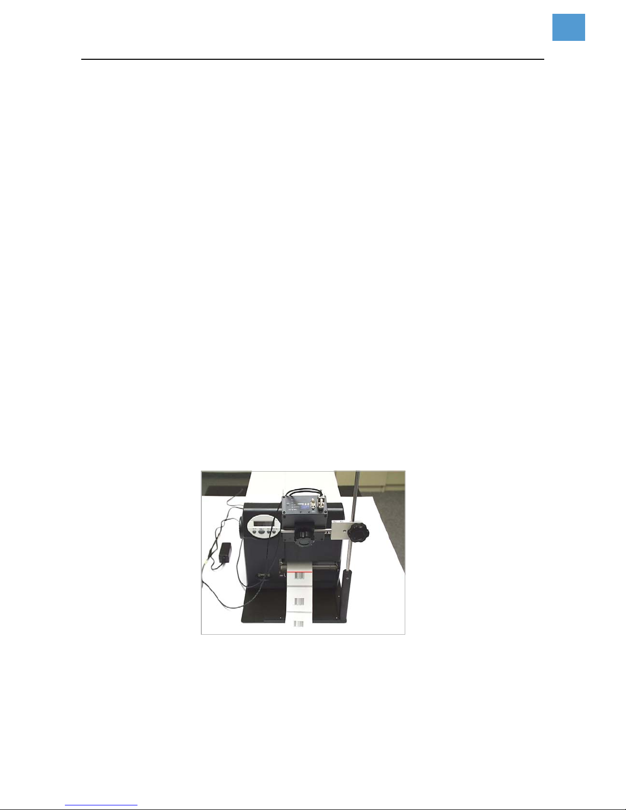
11/14 Rev. 03 USER MANUAL Advanced Applications
AP 4.4 – AP 5.4 – AP 5.6 – AP 7.t – 64-xx – DPM – PEM – ALX 92x
36
Setup
1. Place the printer on the OLV mounting plate as illustrated.
Operating the OLV at a DPM / PEM / ALX 92x requires a support stand match-
ing the respective installation situation
2. Connect the OLV to the serial interface of the printer.
After the printer has been switched on, initialization commands are sent to the
OLV. Therefore, the OLV has first to be switched on. These initialization commands switch on the laser beam (among other things).
The sending of the initialization commands can be repeated at any time by
pressing the Feed and Esc buttons (at the printer) simultaneously. This may be
necessary, if the OLV was switched off.
3. Switch on the OLV.
4. Switch on the printer.
5. Set the printer parameter INTERF. PARAM. > OPTIONS > OLV option to „Serial Com1“
or „Serial Com2“, depending on the port on which the OLV is connected.
(Firmware 3.30: Set the printer parameter INTERF. PARAM. > COM2 PORT >
Function Option to „Barcode OLV“.)
The data transfer parameters of the interface are automatically set to the default
values required by the SV100 (115200 baud, 8 data bits, no parity, 2 stop bits,
hardware handshake).
6. Position the OLV so, that the distance between laser beam (on the label) and printhead is as short as possible.
For detailed information on setting the OLV please refer to the SV100 manual.
7. Set the parameters in the OLV PARAMETERS menu (at the printer).
Information about the parameters can be found in topic section Info-Printouts and
Parameters .
[21] 64-05 with OLV mounted (front view).
Page 76
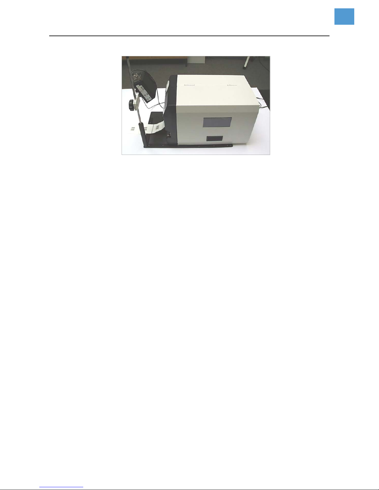
11/14 Rev. 03 USER MANUAL Advanced Applications
AP 4.4 – AP 5.4 – AP 5.6 – AP 7.t – 64-xx – DPM – PEM – ALX 92x
37
[22] 64-05 with OLV mounted (side view).
Page 77

11/14 Rev. 03 USER MANUAL Advanced Applications
AP 4.4 – AP 5.4 – AP 5.6 – AP 7.t – 64-xx – DPM – PEM – ALX 92x
38
Appendix
Example: Setup file for AP 5.4
#!A1
#G Machine Setup for AP 5.4 300 Dpi Version: V3.10
#G Serial number : A424904304797
#G MAC Address : 000a.44.02.13.8c
#G Creation date : 05.05.2006 16:01
#G------------------------------------------------------------------#G Printer Parameter Menu
#G------------------------------------------------------------------#PC1001/1 #G Infeed no. : Nr. 1
#PC1002/8 #G Inf. change spd. : 8 Inch/s
#PC1003/4.0 #G Print speed : 4 Inch/s
#PC1004/4.0 #G Feed speed : 4 Inch/s
#PC1005/1 #G Materialtype : Punched
#PC1006/200.0 #G Materiallength : 200.0 mm
#PC1007/48.0 #G Materialwidth : 48.0 mm
#PC1027/0 #G Print direction : Foot first
#PC1008/0.0 #G Punch offset : 0.0 mm
#PC1009/1 #G Bar code multip. : * 1
#PC1010/0 #G UPC plain-copy : In line
#PC1011/0 #G EAN Readline : Standard
#PC1012/0 #G EAN sep. lines : With readl. only
#PC1013/0 #G Rotated barcodes : Normal
#PC1014/0 #G Cut mode : Real 1:1 mode
#PC1015/3 #G Cut speed : 3 Inch/s
#PC1016/105 #G Cut width : 105 mm
#PC1017/0.0 #G Cut position : 0.0 mm
#PC1018/0.0 #G Double cut : 0.0 mm
#PC1019/1 #G Rewind direction : Printing outside
#PC1020/0.0 #G *X - Printadjust : 0.0 mm
#PC1021/0.0 #G *Y - Printadjust : 0.0 mm
#PC1022/0 #G Punchmode : Automatic
#PC1023/128 #G Punchlevel : 128
#PC1024/30 #G Matend : 30
#G------------------------------------------------------------------#G Easyplug Interpreter
#G------------------------------------------------------------------#PC1101/2 #G Interface : TCP/IP SOCKET
#PC1102/0 #G Spooler mode : Mult. print jobs
#PC1103/1 #G *Printer ID no. : 1
#PC1104/64 #G Spooler size : 64 KBytes
#G------------------------------------------------------------------#G COM1 Port Parameter
#G------------------------------------------------------------------#PC1201/5 #G Baud rate : 9600 Baud
#PC1202/8 #G No. of data bits : 8
#PC1203/2 #G Parity : None
#PC1204/1 #G Stop bits : 1 Bit
#PC1205/0 #G Data synch. : RTS/CTS
#PC1206/0 #G Serial port mode : RS232
#PC1207/1 #G Frame error : Display
Page 78

11/14 Rev. 03 USER MANUAL Advanced Applications
AP 4.4 – AP 5.4 – AP 5.6 – AP 7.t – 64-xx – DPM – PEM – ALX 92x
39
#G------------------------------------------------------------------#G COM2 Port Parameter
#G------------------------------------------------------------------#PC1302/5 #G Baud rate : 9600 Baud
#PC1303/8 #G No. of data bits : 8
#PC1304/2 #G Parity : None
#PC1305/1 #G Stop bits : 1 Bit
#PC1306/0 #G Data synch. : RTS/CTS
#PC1307/0 #G Serial port mode : RS232
#PC1308/1 #G Frame error : Display
#G------------------------------------------------------------------#G COM3 Port Parameter
#G------------------------------------------------------------------#PC1351/2 #G Baud rate : 9600 Baud
#PC1354/1 #G Parity : None
#PC1356/0 #G Data synch. : RTS/CTS
#PC1358/1 #G Frame error : Display
#G------------------------------------------------------------------#G COM4 Port Parameter
#G------------------------------------------------------------------#PC1361/2 #G Baud rate : 9600 Baud
#PC1364/1 #G Parity : None
#PC1366/0 #G Data synch. : RTS/CTS
#PC1368/1 #G Frame error : Display
#G------------------------------------------------------------------#G Centronics Port Parameter
#G------------------------------------------------------------------#PC1401/1 #G PnP function : On
#G------------------------------------------------------------------#G Ethernet Parameter
#G------------------------------------------------------------------#PC1501/0 #G IP Addressassign : DHCP
#PC1502/-1872945967 #G *IP address : 144.093.028.209
#PC1503/-65536 #G *Net mask : 255.255.000.000
#PC1504/0 #G *Gateway address : 000.000.000.000
#PC1505/9100 #G Port address : 9100
#PC1506/0 #G Ethernet speed : Auto negotiation
#PC1521/1 #G SNMP Agent : Enabled
#PC1522/public#G #G SNMP password : public
#PC1507/1 #G FTP server : Enabled
#PC1508/avery#G #G FTP Password : avery
#PC1509/1 #G WEB server : Enabled
#PC1510/5 #G WEB display refr : 5 s
#PC1511/admin#G #G WEB admin passw. : admin
#PC1512/supervisor#G #G WEB supervisor p.: supervisor
#PC1513/AP5.4_300dpi_02138C#G#G DHCP host name : AP5.4_300dpi_02138C
#PC1514/idt#G #G WLAN SSID : idt
#PC1515/0 #G WLAN WEP : Disabled
#PC1516/1 #G WLAN default key : 1
#PC1517/123456789aBCd123456789AbcD#G#G WLAN key 1 : 123456789aBCd123456789AbcD
#PC1518/123456789aBCd123456789AbcD#G#G WLAN key 2 : 123456789aBCd123456789AbcD
#PC1519/123456789aBCd123456789AbcD#G#G WLAN key 3 : 123456789aBCd123456789AbcD
#PC1520/123456789aBCd123456789AbcD#G#G WLAN key 4 : 123456789aBCd123456789AbcD
Page 79

11/14 Rev. 03 USER MANUAL Advanced Applications
AP 4.4 – AP 5.4 – AP 5.6 – AP 7.t – 64-xx – DPM – PEM – ALX 92x
40
#G------------------------------------------------------------------#G Options Parameter
#G------------------------------------------------------------------#PC5300/0 #G Remote Display : Disabled
#G------------------------------------------------------------------#G Printer System Menu
#G------------------------------------------------------------------#PC2001/24.5 #G Head disp dist. : 24.5 mm
#PC2002/0 #G Speed unit : Inch/s
#PC2003/36.4 #G Foil end warning : 36.4 mm
#PC2060/0 #G Foil warn stop : Disabled
#PC2004/0 #G Display mode : Job rest quant.
#PC2005/372 #G *Dispense counter : 372
#PC2006/0 #G w/wo magazine : with
#PC2012/0 #G Print emulation : Easyplug
#PC2013/3 #G Character sets : Germany
#PC2014/0 #G Character filter : Chars >= 20Hex
#PC2015/0 #G Light sens. type : Punched
#PC2016/0 #G Head-sensor dist : 0 mm
#PC2017/50 #G Sens. punch-LS : 50 %
#PC2018/0 #G Foil mode : Thermo transfer
#PC2019/9.9 #G Ribb. eco. limit : 9.9 mm
#PC2058/0 #G Feed mode : Head up
#PC2020/1 #G Turn-on mode : Online
#PC2021/0 #G Interface delay : 0 ms
#PC2022/1 #G Error reprint : Enabled
#PC2023/0 #G Single-job mode : Disabled
#PC2025/1106 #G *Head resistance : 1106 Ohm / 12 Dot
#PC2026/20 #G Temp. reduction : 20 %
#PC2066/1 #G Thin line emphas : On
#PC2027/0 #G Voltage offset : 0 %
#PC2028/1 #G Logo expansion : Yes
#PC2029/0 #G Miss. label tol. : 0
#PC2031/1 #G Periph. device : Cutter
#PC2032/2 #G Infeed module : 2 infeeds
#PC2033/1 #G Singlestartquant : 1
#PC2035/0 #G Application mode : Save mode
#PC2036/0 #G Appl. waitpos. : 0 mm
#PC2037/10 #G Applicator speed : 10 Inch/s
#PC2038/0 #G Start mode : Edge
#PC2039/0 #G Start source : Light barrier
#PC2057/0 #G Calibration mode : Automatic
#PC2042/0 #G External signal : Disabled
#PC2043/0 #G Signal edge : Falling edge
#PC2044/1 #G Apply key : Enabled
#PC2045/99 #G Print contrast : 99 %
#PC2046/512 #G Ram disk size : 512 KBytes
#PC2047/256 #G Font downl. area : 256 KBytes
#PC2048/1024 #G Free store size : 1024 KBytes
#PC2049/2 #G Print info mode : Compact right
#PC2050/0 #G Reprint function : Disabled
#PC2051/1 #G Language : English
#PC2063/1 #G Keyboard : English
#PC2053/0 #G Access authoriz. : Deactivated
#PC2059/80 #G Max InitFeedback : 80 mm
#PC1026/0 #G Material feed : for- / backwards
Page 80

11/14 Rev. 03 USER MANUAL Advanced Applications
AP 4.4 – AP 5.4 – AP 5.6 – AP 7.t – 64-xx – DPM – PEM – ALX 92x
41
#G------------------------------------------------------------------#G Peripheral Parameter Menu
#G------------------------------------------------------------------#PC2512/1 #G Rewinder Motor : Generation 2
#PC2501/0 #G Current mode : Table values
#PC2502/100 #G Min rew. current : 100
#PC2503/250 #G Max rew. current : 250
#PC2504/170 #G Min rew. current : 170 %
#PC2505/170 #G Max rew. current : 170 %
#PC2506/0 #G Start rew. curr. : 0 %
#PC2507/30 #G Start cur. len. : 30 mm
#PC2508/95 #G Pullback current : 95
#PC2509/50 #G Back diameter : 50 mm
#PC2510/0 #G Break current : 0
#PC2511/120 #G Break diameter : 120 mm
#G------------------------------------------------------------------#G Dispenser Interface
#G------------------------------------------------------------------#PC3001/0 #G Interface type : USI interface
#PC3002/0.0 #G Start delay : 0.0 mm
#PC3003/0 #G Start print mode : Pulse falling
#PC3004/0 #G End print mode : Mode 0
#PC3005/0 #G Reprint signal : Disabled
#PC3006/1 #G Ribbon signal : Enabled
#PC3007/0 #G Material signal : Disabled
#PC3013/60.0 #G Diam. mat. end : 60.0 mm
#PC3008/0 #G Feed input : Standard
#PC3012/0 #G Pause input : Standard
#PC3009/0 #G Start error stop : Off
#PC3010/1 #G Internal inputs : Enabled
#PC3011/0 #G Apply mode : After start sig.
#G------------------------------------------------------------------#G Textile Parameter Menu
#G------------------------------------------------------------------#PC3301/1 #G Changelabel Mode : Always at jobend
#PC3302/1 #G Changelab Print : With print
#PC3303/10 #G Changelab Length : + 10 mm
#PC3304/1 #G Label Eject Mode : Yes, at job end
#PC3305/0 #G Head lift autom. : after 0 labels
#G------------------------------------------------------------------#G Applicator Parameter Menu
#G------------------------------------------------------------------#PC3101/0 #G Applicator type : LTP - LTPV
#PC3102/0 #G Apply mode : After start sig.
#PC3110/2 #G Start print mode : Pulse rising
#PC3103/0 #G Start error stop : Off
#PC3104/0 #G APSF sensor res. : 0 pulses/m
#PC3105/0.0 #G Start delay : 0.0 mm
#PC3106/1 #G Dwell time : 1 ms
#PC3107/1 #G Blow on time : 1 ms
#PC3108/0 #G Restart delay : 0 ms
#PC3109/2000 #G Position timeout : 2000 ms
#PC3212/0 #G Start error stop : Off
#G------------------------------------------------------------------#G I/O Board Parameter Menu
#G------------------------------------------------------------------#PC3201/0.0 #G Start delay : 0.0 mm
#PC3202/0 #G APSF sensor res. : 0 pulses/m
#PC3203/0 #G Start print mode : Pulse falling
#PC3204/0 #G Reprint signal : Disabled
#PC3205/0 #G Feed input : Disabled
#PC3206/0 #G Pause input : Disabled
#PC3207/0 #G Error output : Printer error
#PC3208/0 #G Error polarity : Level low active
#PC3209/1 #G Status output : Low ribbon warn.
#PC3210/0 #G Status polarity : Level low active
#PC3211/0 #G End print mode : Mode0 inactive
#G-------------------------------------------------------------------
Page 81

11/14 Rev. 03 USER MANUAL Advanced Applications
AP 4.4 – AP 5.4 – AP 5.6 – AP 7.t – 64-xx – DPM – PEM – ALX 92x
42
#G MLI Parameter Menu
#G------------------------------------------------------------------#PC4002/15 #G Darkness : 15
#PC4003/126 #G Control Prefix : 7EH
#PC4004/94 #G Format Prefix : 5EH
#PC4005/44 #G Delimiter Char : 2CH
#PC4006/0 #G Label Top : 0 Dots
#PC4007/0 #G Left Position : 0 Dots
#PC4009/0 #G Resolution : 300 DPI
#PC4010/0 #G Error Indication : OFF
#PC4011/0 #G Error Checking : YES
#PC4012/0 #G 305 DPI Scaling : YES
#PC4013/0 #G Image Save Path : Internal RAM
#PC4014/1 #G Command ^PR : Enable
#PC4015/1 #G Command ^MT : Enable
#PC4017/0 #G Label Invert : Disable
#PC4016/1 #G Command ^JM : Enable
#G------------------------------------------------------------------#G Printer Special Menue
#G------------------------------------------------------------------#PC5001/1 #G *Printer type : AP 5
#PC5002/1 #G *Printhead type : KPA 300 DPI
#PC5004/0 #G Command sequence : ‚#G‘
#PC5005/0 #G EasyPl. file log : Disabled
#G------------------------------------------------------------------#G Printer Service Menu
#G------------------------------------------------------------------#PC5111/0 #G Spec parameter 1 : 0
#PC5112/0 #G Spec parameter 2 : 0
#PC5113/0 #G EasyPlug Monitor : Disabled
#PC5125/0 #G EP Monitor Mode : Interpreter data
#PC5116/127 #G *Punch adjust : 127
#PC5117/128 #G *Reflex adjust : 128
#PC5119/234 #G *Foil adjust : 234
#PC5120/170 #G *Head sens adjust : 170
#PC5121/0 #G *Optn.1 : 0
#PC5122/0 #G *Optn.2 adjust : 0
#PC5101/35 #G Matend tolerance : 35 mm
#PC5102/0.0 #G Feed adjust : 0.0 %
#PC5103/0.0 #G Foil feed adjust : 0.0 %
#PC5104/0.0 #G *Punch y calibr. : 0.0 mm
#PC5123/31775 #G *Rewinder adjust : 31775
#PC5127/1 #G Debug interface : Serial Com1
#PC5124/0 #G Debug mask : 0
#PC5128/-1872945986 #G Debug IP address : 144.093.028.190
#G------------------------------------------------------------------#G Module Firmware Versions
#G------------------------------------------------------------------#G readonly ID=30004 #G System version : V3.10
#G readonly ID=30052 #G Peripheraldriver : V 3 - T 3
#G readonly ID=30057 #G Intern. rewinder : V 4 - T 36
Page 82

11/14 Rev. 03 USER MANUAL Advanced Applications
AP 4.4 – AP 5.4 – AP 5.6 – AP 7.t – 64-xx – DPM – PEM – ALX 92x
43
#G------------------------------------------------------------------#G Operational Data
#G------------------------------------------------------------------#G readonly ID=30014 #G Serv. operations : 0
#G readonly ID=30015 #G Head number : 0
#G readonly ID=30016 #G Roll number : 0
#G readonly ID=30017 #G Cutter number : 0
#G readonly ID=30018 #G Head run length : 441 m
#G readonly ID=30019 #G Roll run length : 401 m
#G readonly ID=30020 #G Cuts on knife : 881
#G readonly ID=30021 #G Tot. mat. length : 401 m
#G readonly ID=30022 #G Tot. foil length : 358 m
#G readonly ID=30023 #G Total cuts : 881
#G readonly ID=30025 #G Head strobes : 3978688
#G readonly ID=30026 #G Foil diameter : 67.8 mm
#G readonly ID=30028 #G Operation time : 209 hours 46 min
#G------------------------------------------------------------------#G Power supply data
#G------------------------------------------------------------------#G readonly ID=30029 #G Type : Blue Mountain
#G------------------------------------------------------------------#G CPU board data
#G------------------------------------------------------------------#G readonly ID=30034 #G CPU identifier : 25-0
#G readonly ID=30036 #G PCB Revision : REV03
#G readonly ID=30037 #G FPGA version : 5817
#G readonly ID=30039 #G MAC Address : 000a.44.02.13.8c
#G readonly ID=30040 #G Serial number : A424904304797
#G readonly ID=30041 #G Production date : 03.08.2004
#G readonly ID=30042 #G PCB part number : A3407-03
#G readonly ID=30043 #G Board part numb. : A4249-01
#G readonly ID=30044 #G Manufacturer : Multitech Sys
#G readonly ID=30045 #G Work place : FCT Test Station
#G readonly ID=30046 #G Company name : Avery Dennison
#G------------------------------------------------------------------#G CF card slot status
#G------------------------------------------------------------------#G readonly ID=30047 #G Card in slot : Yes
#G readonly ID=30048 #G Card typ : 3.3 Volt
#G------------------------------------------------------------------#G Internal Memory Configuration
#G------------------------------------------------------------------#G readonly ID=30010 #G Space for Jobs : 7.8 MB
#G readonly ID=30007 #G Ram memory size : 16 MB
#G readonly ID=30008 #G Flash mem size : 4 MB FUJ
#G readonly ID=30009 #G Compact flash : 32 MB
#G readonly ID=30010 #G Space for Jobs : 7.8 MB
#G readonly ID=30011 #G Max. Labellength : 1984 mm
#G readonly ID=30013 #G Default values : User defined
#G------------------------------------------------------------------#G Printer Debug Menu
#G------------------------------------------------------------------#PC5403/0 #G Pctrl communica. : Disabled
#PC5402/0 #G Variables : Disabled
#PC5400/0 #G Label generation : Disabled
#PC5401/0 #G Print handling : Disabled
#G------------------------------------------------------------------#G Execute system restart ( 217 parameters )
#G------------------------------------------------------------------#PC999999/-1#G
 Loading...