

Page 1

ProConnect
High Definition Network Video Recorder
User Manual
Page 2

AvertX ProConnect Software (2.0)
Software Manual
Manual Edition 35146AJ – July 2019
©2019, AvertX
All Rights Reserved
No part of this document may be reproduced by any means, electronic
or mechanical, for any purpose, except as expressed in the Software
License Agreement. AVERTX shall not be li able for technical or editorial
errors or omissions contained herein. The information in this document
is subject to change without notice.
The information in this publication is provided “as is” without warra nty of
any kind. The entire risk arising out of the use of this information
remains with recipient. In no event shall AVERTX be liable for any
direct, consequential, incidental, special, punitive, or other d amages
whatsoever (including without limitation, damages for loss of business
profits, business interruption or loss of business information), even if
AVERTX has been advised of the possibility of such damages or
whether in an action, contract or tort, including negligence.
This software and documentation ar e c opyrighted. All other rights,
including ownership of the software, are reserved to AvertX. AVERTX,
and AvertX, are registered trademarks of AVERTX in the United States
and elsewhere; Windows is a registered trademark of Microsoft
Corporation. All other brand and product names are trademarks or
registered trademarks of the respect ive owners.
The following words and symbols mark s pecial messages throughout
this guide:
WARNING: Text set off in this manner indicates that failure to follow
directions could result in bodily harm or loss of life.
CAUTION: Text set off in this manner indicates that failure to follow
directions could result in damage to equipment or loss of
information.
Note Text set off in this manner indicates i nformation that is
necessary for proper operation of the product.
AVERTX
35146AJ
2
Page 3

Standard Warranty
All products, purchased through Av ertX and its authorized resellers, ar e
warranted to be free from defects in material or workmanship under
normal use for two years from date of shipment. At AvertX’s discretion,
defective products under warranty will be repaired or replaced at no
cost. If AvertX determines that the product should be replaced, it may
do so with new or refurbished product s of equal or greater
value. Product warranty does not cover product failure caused by
misuse, alteration of the produc t, incorrect installation, electric surges or
physical damage.
Exceptions to the two-year warranty include:
• Discontinued products sold by AvertX are warranted one year from
the date of shipment
• Refurbished Performance Series NVRs sold by AvertX are
warranted for one year from the date of shipment
• All other refurbished products sol d by AvertX are warranted for six
months from the date of shipment
• New products purchased prior to J anuary 1, 2014 are warranted for
one year from the date of shipment
There is no other warranty provided by AvertX, express or implied
including without limitation t he warranties of merchantability and fitness
for a particular purpose. Under no circumstances will AvertX be liable
for any consequential, incidental, special or exemplary damages arising
out of or connected with the sale, del ivery, use or performance of the
product, even if AvertX is apprised of the likelihood of such damages
occurring. In no event shall AvertX liability exceed the purchase price of
the product. This warranty gives you specific legal rights and you ma y
also have other rights which vary from s tate to state or country to
country.
For the most up to date information visi t www.avertx.com.
IMPORTANT SAFEGUARDS
1. Read Owner’s Manual – After unpacki ng this product, read
the owner’s manual carefully, and follow all the operating and
other instructions.
2. Power Sources – This product should b e operated only from
the type of power source indicated on th e label. If not sure of
the type of power supply to your home or business, consult
product dealer or local power company.
3. Ventilation – Slots and openings in the cabinet are provided
for ventilation and to ensure reliab l e operation of the product
and to protect it from overheating, and these openings must
not be blocked or covered. The product s hould not be placed in
a built-in installation such as a bookc ase or rack unless proper
ventilation is provided or the manufac turer’s instructions have
been adhered to.
4. Heat – The product should be situated away from heat sources
such as radiators, heat registers , stoves, or other products that
produce heat.
5. Water and Moisture – Do not use this product near water.
6. Cleaning – Unplug this product from the wall outlet before
cleaning. Do not use liquid cleaners or aerosol cleaners. Use a
damp cloth for cleaning.
7. Power Cord Protection – Power-supply cords should be
routed so that they are not likely to be walked on or pinched by
items placed against them, paying particular attention to cords
at plugs, convenience receptacl es , and the point where they
exit from the product.
8. Overloading – Do not overload wall outlets, extension cords,
or integral convenience receptacles as this can result in a risk
of fire or electrical shock.
9. Lightning – For added protection for this product during storm,
or when it is left unattended and unused for long periods,
unplug it from the wall outlet. T hi s will prevent damage to the
product due to lightning and power line surges.
10. Object and Liquid Entry Points – Never insert foreign objects
into the recorder, other than the media types approved by
AvertX, as they may touch dangerous voltage points or s hortout parts that could result in a fire or electrical shock. Never
spill liquid of any kind on the produc t.
11. Accessories – Do not place this produc t on an unstable cart,
stand, tripod, bracket, or table. The product may fall, causing
serious personal injury and ser ious damage to the product.
12. Burden – Do not place a heavy object on or step on the
product. The object may fall, causing serious personal injury
and serious damage to the product.
35146AJ
3
Page 4

13. Damage Requiring Service – Unplug the unit from the outlet
and refer servicing to qualified service personnel under the
following conditions:
• When the power-supply cord or plug is damaged.
• If liquid has been spilled, or object s have fallen into the unit.
• If the unit has been exposed to rain or water.
• If the unit does not operate normally by following the operating
instructions. Adjust only thos e c ontrols that are covered by the
operating instructions as an improper adjustment of other
controls may result in damage and will often require extensive
work by a qualified technician to r es tore the unit to its normal
operation.
• If the unit has been dropped or the enclosure has been
damaged.
• When the unit exhibits a distinct change in performance – this
indicates a need for service.
14. Servicing – Do not attempt to service this product as opening
or removing covers may expose the user to dangerous voltage
or other hazards. Refer all servicing to qualified personnel.
15. Replacement Parts – When replacement parts are required,
be sure the service technician has used replacement parts
specified by the manufacturer or hav e the same characteristics
as the original part. Unauthoriz ed substitutions may result in
fire, electric shock or other hazards.
Safety Check – Upon completion of any service or repairs to this unit,
ask the service technician to perfor m safety checks to determine that
the unit is in proper operating condit ion.
BATTERY EXPLOSION CAUTION STATEMENT
CAUTION: Risk of Explosion if Battery is replaced by a n Incorrect Type.
Dispose of Used Batteries According to the Instructions.
HANDLING
Please retain the original shipping carton and/or packing materials supplied
with this product. To ensure the integrity of this product when shipping or
moving, repackage the unit as it was ori ginally received from the
manufacturer.
Do not use volatile liquids, such as aer osol spray, near this product. Do not
leave rubber or plastic objects i n c ontact with this product for extended
periods of time. Rubber or plastic obj ec ts left in contact with this product for
extended periods of time will leave mark s on the finish.
The top and rear panels of the unit ma y become warm after long periods of
use. This is not a malfunction.
LOCATING
Place this unit on a level surface. Do not us e it on a shaky or unstable
surface such as a wobbling table or inc l ined stand.
If this unit is placed next to a TV, radio, or VCR, the playback picture may
become poor and the sound may be distorted. If this happens, place the
recorder away from the TV, radio, or VC R.
CLEANING
Use a soft dry cloth for cleaning.
For stubborn dirt, soak the cloth in a weak detergent solution, wring well and
wipe. Use a dry cloth to wipe it dry. Do not use any type of solvent, such as
thinner and benzene, as they may dama ge the surface of the recorder.
If using a chemical saturated cloth t o clean the unit, follow that produc t’s
instructions.
MAINTENANCE
This recorder is designed to last for long periods of time. To keep the
recorder always operational we recommend regular inspection maintenanc e
(cleaning parts or replacement). For details, contact the nearest deal er .
MOISTURE CONDENSATION
Moisture condensation damages the recorder. Read the following
information carefully.
Moisture condensation occurs dur i ng the following cases:
• When this product is brought directly from a cool location to a warm
location.
• When this product is moved to a hot and h umid location from a cool
location.
35146AJ
4
Page 5

• When this product is moved to a cool and humid location from a
warm location.
• When this product is used in a room where the temperature
fluctuates.
• When this product is used near an air-c onditioning unit vent
• When this product is used in a humid location.
Do not use the recorder when moisture condensation may occur.
If the recorder is used in such a situation, it m ay damage discs and internal
parts. Remove any CD discs, connect the power cord of the recorder to the
wall outlet, turn on the recorder, and leave it for two to three hours. After two
CAUTION
to three hours, the recorder will warm up and evaporate any moisture. Kee p
the recorder connected to the wall and moistur e will seldom occur.
WARNING
TO REDUCE THE RISK OF ELECTRICAL SHOCK, DO NOT EXPOSE
THIS APPLIANCE TO RAIN OR MOISTURE.
DANGEROUS HIGH VOLTAGES ARE PRESENT INSIDE THE
ENCLOSURE.
DO NOT OPEN THE CABINET.
REFER SERVICING TO QUALIFIED PERSONNEL ONLY.
RACK MOUNT INSTRUCTIONS
Elevated Operating Ambient – If installed in a closed or multi-u ni t rack assembly, the operating ambient temperature of the rack environment may be greater
than room ambient. Therefore, cons ideration should be given to installing the equipment in an environment c ompatible with the maximum am bient temperature
(Tma) specified by the manufacturer.
Reduced Air Flow – Installation of the equipment in a rack should be such t hat the amount of airflow required for saf e operation of the equipment is not
compromised.
Mechanical Loading – Mounting of the equipment in the rack should be such t hat a hazardous condition is not achiev ed due to uneven mechanical loading.
35146AJ
5
Page 6

Circuit Overloading – Consideration should be given to the connection of the equipment to the supply circuit and the effect that overloading of the circuits mi ght
have on over current protection and supply wiring. Appropriate consideration of equipment nameplate ratings should be used when addressing this concern.
Grounding – Grounding of rack-mounted equipment should be maintained. Particular attention s hould be given to supply connections ot her than direct
connections to the branch circuit (e.g. use of power strips).
FCC STATEMENT
INFORMATION TO THE USER: THIS PRODUCT HAS BEEN TESTED AND FOUND TO COMPLY WITH THE LIMITS FOR A CLASS A
DIGITAL DEVICE PURSUANT TO PART 15 OF THE FCC RULES. THESE LIMITS ARE DESIGNED TO PROVIDE REASONABLE
PROTECTION AGAINST HARMFUL INTERFERENCE WHEN THE EQUIPMENT IS OPERATED IN A COMMERCIAL ENVIRONMENT. THE
PRODUCT GENERATES, USES, AND CAN RADIATE RADIO FREQUENCY ENERGY, AND, IF NOT INSTALLED AND USED IN
ACCORDANCE WITH THE MANUFACTURER’S INSTRUCTION MANUAL, MAY CAUSE HARMFUL INTERFERENCE WITH RADI O
COMMUNICATIONS. OPERATION OF THIS PRODUCT IN A RESIDENTIAL AREA IS LIKELY TO CAUSE HARMFUL INTERFERENCE, IN
WHICH CASE YOU WILL BE REQUIRED TO CORRECT THE INTERFERENCE AT YOUR OWN EXPENSE.
THESE LIMITS ARE DESIGNED TO PROVIDE REASONABLE PROTECTION AGIANST HARMFUL INTERFERENCE IN A NONRESIDENTIAL INSTALLATION. HOWEVER, THERE IS NO GUARANTEE THAT INTERFERENCE WILL NOT OCCUR IN A PARTICULAR
INSTALLATION. IF THIS EQUIPMENT DOES CAUSE HARMFUL INTERFERENCE WITH THE RADIO OR TELEVISION RECEPTION, WHICH
CAN BE DETERMINED BY TURNING THE EQUIPMENT OFF AND ON, YOU ARE ENCOURAGED TO TRY TO CORRECT THE
INTERFERENCE BY ONE OR MORE OF THE FOLLOWING MEASURES.
• REORIENT OR RELOCATE THE RECEIVING ANTENNA.
• INCREASE THE SEPARATION BETWEEN THE EQUIPMENT AND RECEIVER.
• CONNECT THE EQUIPMENT TO A N OUTLET ON A CIRCUIT DIFFERENT FROM THAT TO WHICH THE RECEIVER IS
CONNECTED.
• CONSULT THE DEALER OR AN EXPERIENCED RADIO/TV TECHNICIAN FOR HELP.
CAUTION: CHANGES OR MODI F ICATIONS NOT EXPRESSLY APPROVED BY THE PARTY RESPONSIBLE FOR COMPLIANCE COULD
VOID THE USER’S AUTHORITY TO OPERATE THE EQUIPMENT.
THIS CLASS A DIGITAL APPARATUS COMPLIES WITH CANADIAN ICES-003.
CET APPAREIL NUMÉRIQUE DE LA CLASSE B EST CONFORME À LA NORME NMB-003
DU CANADA.
OPERATION OF THIS DEVICE IS SUBJECT TO THE FOLLOWING CONDITIONS:
• THIS DEVICE MAY NOT CAUSE HARMFUL INTERFERENCE.
• THIS DEVICE MUST ACCEPT INTERFERENCE RECEIVED, INCLUDING INTERFERENCE THAT MAY CAUSE UNDESIRABLE
OPERATION.
• CABLES USED WITH THIS DEVICE MUST BE PROPERLY SHIELDED TO COMPLY WITH THE REQUIREMENTS OF THE FCC.
• ANY CHANGES OR MODIFICATIONS NOT EXPRESSLY APPROVED IN THIS MANUAL COULD VOID YOUR AUTHORITY TO
OPERATE THIS EQUIPMENT.
35146AJ
6
Page 7

USERS OF THE PRODUCT ARE RESPONSIBLE FOR CHECKING AND COMPLYING WITH ALL FEDERAL, STATE, AND LOCAL LAWS AND STATUTES
CONCERNING THE MONITORING AND RECORDING OF VIDEO A ND AUDIO S IGNALS. AVERTX SHALL NOT BE HELD RESPONSIBLE FOR THE USE
OF THIS PRODUCT IN VIOLATION OF CURRENT LAWS AND STATUTES.
35146AJ
7
Page 8

TABLE OF CONTENTS
INTRODUCTION ............................................................................................................................................................................................................................ 10
Product Description ................................................................................................................................................................................................ 10
Features ................................................................................................................................................................................................................. 10
Controls and Connections ...................................................................................................................................................................................... 11
ProConnect Front Panel .................................................................................................................................................................................. 11
ProConnect Rear Panel (8 Channel) ............................................................................................................................................................... 11
ProConnect Rear Panel (16 Channel) ............................................................................................................................................................. 12
Getting Started ....................................................................................................................................................................................................... 13
Box Contents ................................................................................................................................................................................................... 13
Keyboard Setup ............................................................................................................................................................................................... 14
Mouse Setup ................................................................................................................................................................................................... 14
Monitor Setup .................................................................................................................................................................................................. 15
Connecting a Camera Using a PoE Port ......................................................................................................................................................... 15
Setting Up the Recorder for the First Time ............................................................................................................................................................. 16
Turning On the Recorder ........................................................................................................................................................................................ 16
Turning Off the Recorder ........................................................................................................................................................................................ 16
WEB INTERFACE SYSTEM REQUIREMENTS ............................................................................................................................................................................ 17
INSTALLATION AND SETUP ....................................................................................................................................................................................................... 18
Default Administrator Username / Password ................................................................................................................................................... 18
First Time Wizard ............................................................................................................................................................................................ 18
SETUP MENU ................................................................................................................................................................................................................................ 18
System Settings ...................................................................................................................................................................................................... 18
Cameras .......................................................................................................................................................................................................... 18
Advanced Camera Management ..................................................................................................................................................................... 25
Settings ........................................................................................................................................................................................................... 26
Networking ...................................................................................................................................................................................................... 31
Macros............................................................................................................................................................................................................. 32
Sensor / Relay ................................................................................................................................................................................................. 33
AvertX Connect ............................................................................................................................................................................................... 35
35146AJ
8
Page 9

Power Options ................................................................................................................................................................................................. 36
Support Tools (local) .............................................................................................................................................................................................. 36
To Enter Support Tools: .................................................................................................................................................................................. 36
Advanced Network Management ............................................................................................................................................................................ 36
LIVE SCREEN VIEWING PANE .................................................................................................................................................................................................... 37
Navigation Bar ........................................................................................................................................................................................................ 38
Right-Click Menu .................................................................................................................................................................................................... 38
Customizing the Live Screen .................................................................................................................................................................................. 39
How Do I Add / Remove Cameras from The Live Screen Display? ................................................................................................................. 39
How Do I Adjust the Grid of Camera Til es i n The Viewing Pane? ................................................................................................................... 39
How Do I Adjust the Live Screen Vie w? .......................................................................................................................................................... 39
How do I Adjust the Live Video Stream Quality? ............................................................................................................................................. 39
How Do I Enable and Control PTZ? ................................................................................................................................................................ 40
How Do I Enable Fullscreen? .......................................................................................................................................................................... 40
How Do I Turn the OSD ON / OFF? ................................................................................................................................................................ 40
Digital Zoom .................................................................................................................................................................................................... 40
PERFORMING A SEARCH ........................................................................................................................................................................................................... 41
How Do I Perform a Date / Time Search Via a R ec order? .............................................................................................................................. 41
How Do I Perform a Timeline Search (Web Interface Only) ............................................................................................................................ 42
How do I Perform an Event Search (Web Interface Only)? ............................................................................................................................. 44
How Do I Perform a Thumbnail Search (W eb Interface Only) ......................................................................................................................... 45
How Do I Export from Search? ........................................................................................................................................................................ 46
Export Archives Locally (Local Console Only) ................................................................................................................................................. 47
How Do I Export Video from the Console with No OSD? ................................................................................................................................ 48
How Do I View Exported Video Clips in A vertX Connect? ............................................................................................................................... 48
How Do I Enable Email Alerts and push notifications for Motion, Sensor or H ealth Events? ................................................................................. 49
35146AJ
9
Page 10

INTRODUCTION
PRODUCT DESCRIPTION
AvertX ProConnect cloud managed recorders are turn-key appliances
designed for hassle free, plug-n-play installation. AvertX ProConnect
model recorders come equipped with an integrated PoE switch for
connecting IP cameras directly t o the recorder, and come preloaded
with AvertX’s powerful ProConnect S oftware recording software.
All AvertX ProConnect recorders are designed for deployment with
AvertX Connect, allowing central ized administration of users,
permissions, and system settings. These recorders also utilize AvertX’s
Web Connect technology for single sign-on, roaming profiles, and
automated internet connectivity.
To learn more about the ProConnect model recorder or the rest of
recorder lineup visit www.AvertX.com
.
FEATURES
AvertX ProConnect recorders inclu de the following features:
• Fully integrated with AvertX Connect
• Complete remote operation and adm i nistration with AvertX
Connect
• Record up to 24 channels of IP video per recorder (using
external PoE Switch)
• Up to 20TB on-board storage
• Online User Management via AvertX Connect
• Cloud video export and sharing
• Remote software updates with no need t o be on-site
• Advanced cyber security including multi-factor authentication
for remote access
• Mobile apps available for Android, iOS and Apple TV
35146AJ
10
Page 11

CONTROLS AND CONNECTIONS
USB 2.0
USB 3.0
Power Switch
USB 2.0
External
HD Out
Power Input
Internet NIC
Alarm I/O
VGA
PoE Ports
Generation 2 hardware shown. Por ts and layout may vary slightly.
ProConnect Front Panel
ProConnect Rear Panel (8 Channel)
Switch NIC
35146AJ
11
Page 12

ProConnect Rear Panel (16 Channel)
External
Switch NIC
Internet NIC
USB 3.0
Power Switch
USB 2.0
HD Out
Alarm I/O
VGA
PoE Ports
Power Input
35146AJ
12
Page 13
GETTING STARTED
Box Contents
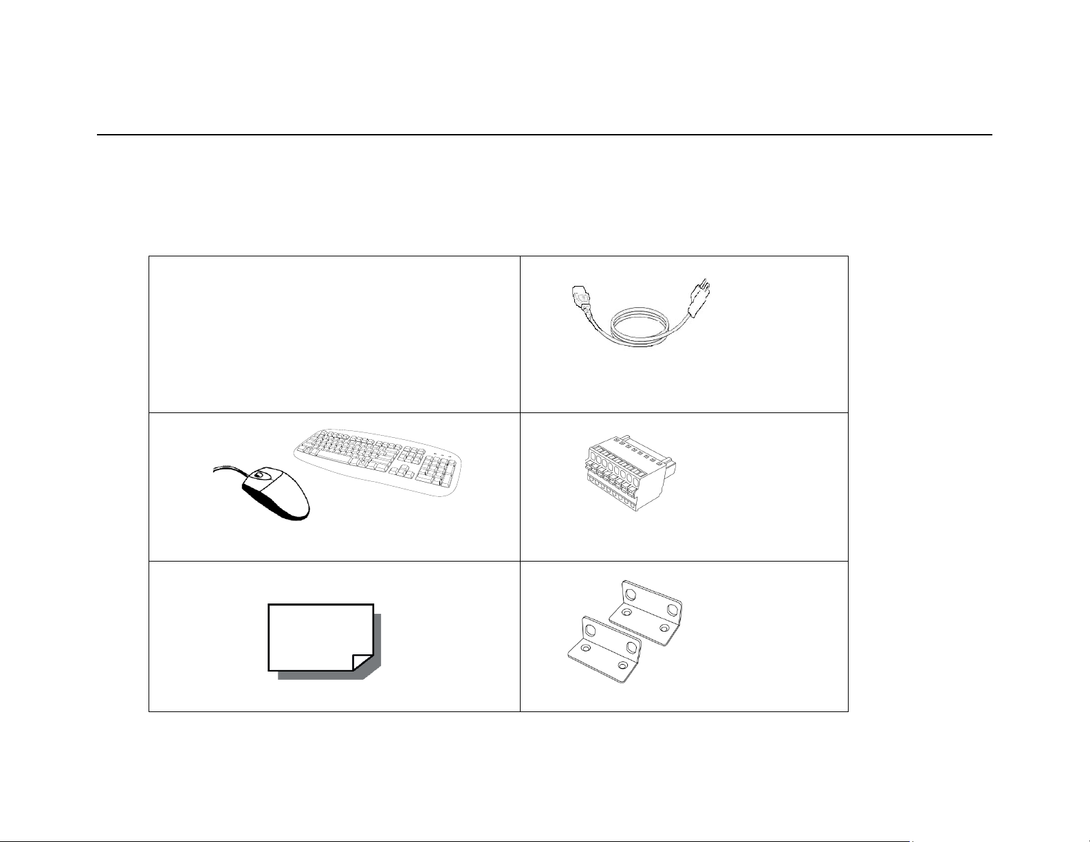
AvertX ProConnect recorders come with a power cord, keyboard and mouse. A Quick Start guide and other necessary document ation are also included.
Identify the following components to make sure everything has been properly included with your new recorder. I f any of the following items are missing,
contact AvertX Pro Team Support at 855-228-3789 to arrange a replacement.
ProConnect Recorder Power Cord
Keyboard and Mouse Alarm I / O Block
QuickStart Guide Rack Mount Installation Kit
35146AJ
13
Page 14
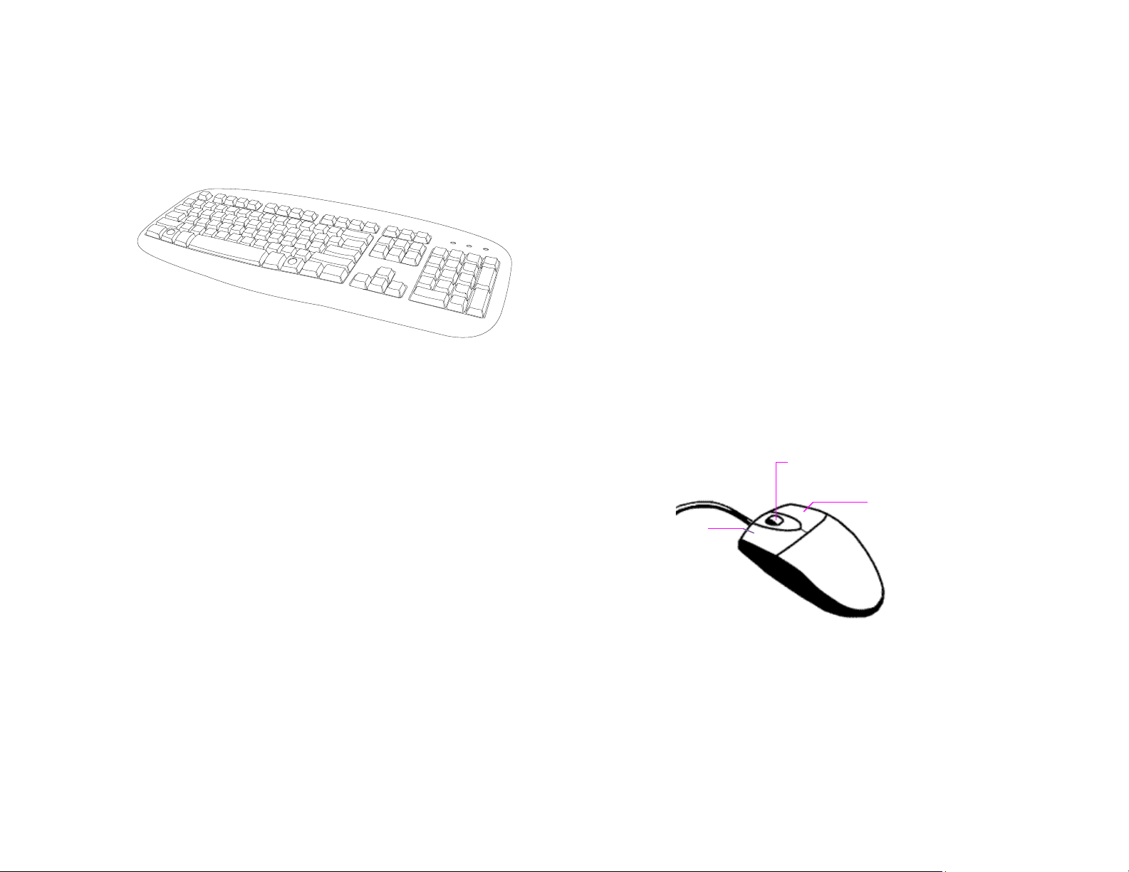
Keyboard Setup
Left Button
Scroll Button / Third
Right Button
Mouse Setup
To attach the keyboard, connect t he keyboard to a USB port located on
the back of the recorder.
To attach the mouse, connect the mouse to a USB port located on the
back of the recorder.
In this manual:
Click means to position the mouse cursor over an item and to single
click the left button.
Right-click means to position the mouse cursor ov er an i tem and to
single click the right button.
Double-click means to position the mouse cursor over an item and to
click the left button twice in quick succession.
Select means to position the mouse cursor over a radio button,
checkbox, or list item, and then click on it.
The scroll wheel in between the two buttons is used for added
navigation functionality. By moving the wheel with index finger
(scrolling), quickly move through multiple pag es, lines, or windows. The
wheel may also function as a third button allowing the user to quickly
click or double-click an icon or a selected item.
35146AJ
14
Page 15
Monitor Setup
Connecting a Camera Using a PoE Port
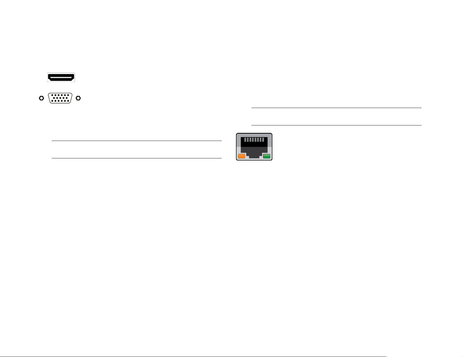
These connections are available to c onnect a monitor:
HDMI® Output To TV / Digital Display
VGA Output To TV / Analog Monitor
Attach the monitor(s) to the rear of the recorder using the cable supplied
by the monitor manufacturer. Refer to the monitor manual for detailed
information on how to setup and use it .
Note The monitor must be capable of a minimum screen resolution
of 1024x768 and support 32-bit color.
The ProConnect recorder is equipped with an on-board Power over
Ethernet (PoE) switch for use with PoE IP cameras. PoE cameras are
connected to the recorder using the PoE switch and begin displaying
video immediately with no manual c onfiguration required.
Connect one end of the CAT 5 Ethernet ca ble to the RJ-45 connector of
the camera and the other end of the cable t o the network switch or
recorder.
Note If you are connecting the camera directly to a recorder, a
crossover cable is necessary for most configurations.
Check the status of the link indicator and activity indicator
LEDs. If the LEDs are unlit, check the LAN connection.
The Orange activity light flashes to indicate network activity.
The Green link light indicates a good network connection.
35146AJ
15
Page 16

SETTING UP THE RECORDER FOR THE
TURNING ON THE RECORDER
FIRST TIME
1. Plug the supplied power cord into the recorder. Do NOT connect
the power cord to a power source at this t i m e.
2. Connect the network cable intended for remote connection to the
Internet NIC.
Note The External Switch NIC is intended for use wit h a dedicated
camera network with an accessory PoE Switch.
1. Connect the supplied keyboard and mouse using the
rear USB ports.
2. Connect a monitor using the HDMI or VGA ports.
3. Connect the cameras to PoE ports, if available.
4. Connect the power cord to a power source, and then
turn the recorder ON.
5. Log in to the ProConnect recorder using the default
credentials:
• Username: admin
• Password: 1234
6. Follow the Setup Wizard to complete basic setup of your
system.
1. Turn on the monitor connected to your recorder.
2. Use the power switch on the rear of the rec order to turn the
recorder ON.
3. The recorder will run a series of self-tests. If asked to respond to
any messages, follow the instruct ions carefully.
Startup is complete when the ProConnect software is finished loading
and displays the main login screen.
TURNING OFF THE RECORDER
1. Click Setup, and then click Power Off / Restart.
2. Click Power Off.
35146AJ
16
Page 17

WEB INTERFACE SYSTEM REQUIREMENTS
ProConnect can be accessed locally via the ProConnect Local or remotely via the ProConnect Web Interface. The Web Inter face runs in a HTML5
environment, making it compatible with a wide range of browsers and without additional software installation.
Minimum Browser Requirements
64-bit Windows® 7, 8.1 or 10 with DirectX support
6th Generation Intel® Dual Core™ i3 processor (or equivalent)
8 GB system memory
1366x768 Resolution Monitor
Latest versions of Google Chrome, Mozilla Firefox, Apple Safari
Broadband internet connection (25 M b/s download, 5 Mb/s upload)
For more information about config uring AvertX Connect, see the AvertX Connect Account section of this manual.
Recommended Browser Requirem ents
64-bit Windows® 7, 8.1 or 10 with DirectX support
7th Generation Intel® Quad Core™ i5 (or better)
8 GB system memory
1920x1080 Resolution Monito r
Latest versions of Google Chrome, Apple Safari
Broadband internet connection (25 M b/s download, 5 Mb/s upload)
35146AJ
17
Page 18

INSTALLATION AND SETUP
Add Cameras
Camera List
Edit Sort Order
Multi-Camera Edit
SETUP MENU
Note ProConnect software setup can be perfor med through the
ProConnect recorder local interf ac e or through the web
browser Web Interface.
Default Administrator Username / Password
When ProConnect is launched, you will be prompted to login. The
default Administrator username and password are as follows:
Username: admin
Password: 1234
Note Once registered to AvertX Connect, your AvertX Connect
credentials can be used to log in, in addition to the default
credentials listed above.
First Time Wizard
The First Time Wizard can be accessed from both the web interface and
locally, and will guide you through a bas ic setup of your ProConnect
recorder. If you wish to make system c hanges after the initial setup
process using the First Time Wizard, these options can be found in
System Settings, User Management, and Network Configuration.
The Setup Wizard will run the first time the recorder is powered on. If
you click the X, you will be given the option to dismiss it temporarily (it
will run next time the recorder powers on) or to dismiss it forever.
SYSTEM SETTINGS
Cameras
Camera Management
Use Camera Management to perform basic and advanced camera
functions.
Camera List – List of cameras currently connected to the selected
recorder.
IP Address – The current IP address of the camera.
State – The current camera state.
• Enabled: The camera is enabled, active, and recording.
• Disabled: The camera is disabled, but previously recorded
video is still available.
Add Camera – Add a camera(s) to the Camer a List.
Advanced – Launches Network Camera Manager (Console Only)
Edit Sort Order – The order the cameras will be displayed in local and
remote clients.
Multi-Camera Edit – Delete cameras, update im ages, change
recording types, and other options to multiple cameras at once.
Sort By – Order cameras by State, Name, Model, or IP Address.
35146AJ
18
Page 19

Search – Search for a camera in the Cam era List.
Delete or Disable [x] – Deleting a camera will remove the camera and
all associated video from the record er. To remove the camera but keep
the video, select Mark as Disabled instead.
Add Cameras
1. Click Setup .
2. Under the System Settings tab, click Cameras.
3. Click Add Cameras. The add camera menu will appear, and
automatically discover support ed c ameras available on the
physically connected network.
4. Check the appropriate boxes to select the camera(s) you wish to
add.
5. Enter the appropriate credenti als (username and password) for the
cameras you wish to add, and then click Add Selected Cameras.
Note Supported cameras will automatically populate the
manufacturer’s default userna me and password when
possible.
Manually Add a Camera – Enter camera information manually to add it
to the Camera List.
Refresh – Refresh the camera list to r eflect changes.
Add Selected Cameras – Check the bo xes to add the cameras
selected from the Add Camera list t o the Camera tab.
Camera Name – The make and model of the camera.
IP Address – The IP address of the camera.
Subnet Mask – The subnet mask of the camer a.
Static/DHCP – Set the device to Static or DHCP
Enter Custom Name – Enter a custom name for the camera to make it
more easily identifiable.
Username / Password – The necessary credentials to access the
camera.
35146AJ
19
Page 20

Camera Auto-Discovery
ProConnect recorders automatic al ly configure cameras attached to the
onboard PoE switch. Cameras not connected to the PoE switch will
automatically be discovered, but need to be configured via the Add
Camera menu.
Note Automatic configuration Plug N P l ay (PnP) of cameras
attached to the PoE switch can be disabled by navigating to
Networking, clicking the Plug and Play tab, and unchecking
the box labelled Enable Plug and Play.
Add Cameras Manually
If you do not see the camera you wish to add in the Add Cameras list, it
may be necessary to add it manually.
1. Click Setup .
2. Under the Settings tab, click Cameras.
3. Click Add Cameras, then Manually Add Camera.
4. Enter the appropriate connecti on information to add the camera,
including Protocol, IP Address, Port, Manufacturer, Model,
Username, Password, and Camera Name.
5. Click Add Camera.
Note Cameras can be added using AvertX, ONVIF or RTSP
protocols. If RTSP is selected, t he stream URLs need to be
input manually. Consult your camera manufacturer’s
documentation for URL stream inf ormation.
Note The camera image will not be immediat ely available. The
image will be visible after clicking Apply and the connection to
the camera is made.
Edit Cameras
To edit an existing camera in the Camer a List:
1. Click the desired camera in the Camera List.
2. In the camera window, make the desir ed changes, and then click
Update Image to update the camera image.
3. Click Apply, and then click Save.
Note Automatic configuration Plug N Play (PnP) of cameras
attached to the PoE switch can be disabled by navigating to
Networking, clicking the Plug and Play tab, and unchecking the
box labelled Enable Plug and Play.
35146AJ
20
Page 21

Title – Customizable camera name, seen on the Camera List and in the
Live Screen.
State – Set the camera to Enabled or Disabl ed.
• Enabled: Uses a recording channel license, can be viewed in
live and recorded.
• Disabled: Does not use a recording channel license and
cannot be viewed in live or recorded.
Associate Camera – Select another c amera to transfer camera
information to in case of hardware f ailure or change in camera status .
IP/Port – Camera IP address and Port Number. Cl icking the IP address
in a web browser allows direct access to the camera’s web setup menu.
Username and Password – Credentials to access camera. Click to
view Password.
Enable PTZ/Autofocus – Enable Pan, Tilt, Zoom (PTZ) capabilities. If a
camera does not have PTZ capabiliti es , this option will be unavailable.
Hidden Camera – Enable to allow only users with hidden camera
permissions to view this camera.
IP Address – Clicking the IP address in a web browser allows direct
access to the camera’s web setup menu.
Synchronize – Manual check of IP device for latest information.
Model – Model number of the camera (transmitted f rom the camera
itself).
Integration ID – Integration ID is the channel number used in 3
integrations over the API.
Update Image – Update the thumbnai l i m age for this camera to the
current live view.
rd
party
Live / Recording
The Live Recording tab displays Recor ding Options, which determines
when and how the camera will record.
Motion – Record only motion detected by motion t hresholds.
Continuous – Records video stream continuously.
Continuous + Motion – Record one Continuous stream, and then
records a Motion stream in addition when motion is detected.
Live Only (No Recording) – Camera displays live video but does n ot
record unless a macro is setup to record on sensor events.
Continuous Recording Stream – Stream continuously recorded at a
lower resolution and/or frame rat e when motion is not detected and
Continuous + Motion recording opti on i s selected.
Motion/Event Recording Stream – Higher r esolution and/or frame rate
camera video stream used when a motio n event is detected.
Collect Motion Event Data – This function collects motion event data
when a continuous stream is recording and populates the events in
Event Search.
35146AJ
21
Page 22

Stream Configuration & Remote Viewing – This is where you
designate what high, medium, and low-quality streams are. You can
choose one of these as the recording str eam, and the system
automatically chooses the highes t res stream under 720x576 (D1) to
use for motion detection. These streams are also used as high,
medium, and low-quality streams in the live view.
Note If at least one resolution at 720x576 or be low is not available,
the following warning below will appear.
Note Smart codec should not be enabled on the secondary stream
that is used for video motion detection. For devices using
single stream, smart codec should be disabled for video
motion detection.
Image Settings
The Image Settings tab displays Picture Adjustment Settings and
Exposure Settings. These settings have a direct correlation to the
camera performance and recorded v ideo quality. The settings displayed
here are options made available t hrough the appropriate drivers. Mak ing
changes to these settings will then push the changes to the camera.
Select to adjust the camera settings.
Brightness – Depth of light and shadow in the image.*
Saturation – Depth of color in the image.*
Sharpness – Manage image texture, par ticularly visible in dark
scenes.*
Contrast – Difference between brig ht and dark areas of the image.*
White Balance – Select Manual to adj us t preset colors corresponding
to natural or artificial lighting for the most accurate color representat ion.
Wide Dynamic Range – Select On to enhance details both in the
foreground and background.**
IR Function – Activate the camera IR (infrared) lights if available, for
use with night-time recording.
Shutter – Select Manual to designate shutt er speed. Longer shutter
speed will increase visibility at night, but also result in blurred movem ent
in the frame.**
Rotate – Allows the camera to be flipped 90, 180 or 270 degrees.
* This option can drastically affect the quality of recorded video. The
default value is recommended.
**Using this option results in impr ov ed video quality but increases
recorded video file size.
35146AJ
22
Page 23

Motion
AvertX cameras are set to register motion as events in the video
timeline. By default, the entire camera will be configured as a motion
area. You can customize areas of t he field of view that will register
motion events.
Motion Sensitivity – Reduce or increase the sensitivit y of motion
detection.
Noise Sensitivity – Reduce or increase noise sensitivity detected o n a
camera.
Image Offset – Offset when an image is captured from a motion event.
Reset Defaults – Resets motion sensitivity and noise sensitivity back to
default values.
Select – Allows motion detection gr i ds to be moved.
Select All – Draws a full motion detection grid over the image.
Add Motion Area – Draw individual motion detection grids.
Remove Motion Area – Allows removal of motion detection grid areas
within a grid.
Clear All – Removes all motion detection area grids.
To Configure Motion:
1. Click Setup , then Cameras.
2. Click the desired camera in the Camera List.
3. Click the Motion tab.
4. Click Add Motion Area or Remove Motion Area, and then click
and drag the capture square to create t he area.
Note By default, the entire camera will be configured as a motion
area.
5. Continue modifying Motion Areas as desired using the tools below
the camera frame.
Note Motion Areas can be subtracted to dis able motion detection
for specific areas of the video stream and motion grids can be
drawn over each other.
6. Click Save.
35146AJ
23
Page 24

Audio
Note With Audio Recording enabled, recorded audio from a camera
can only be heard when a video file is e xported. You will not
be able to hear live or recorded audio direct from the recorder
audio out, from the web viewer or from mobile apps.
Before enabling this option, ensur e that audio is already enabled on the
camera. If audio is enabled on the recorder prior to enabling it on the
camera, audio may not record until the recorder is restarted.
Audio Options:
1. Check Enable Audio Recording to enable audio recording on a
specific IP camera.
2. Then click Save or Apply.
Note Audi o m ust be enabled on the IP camera itself with the G.711
or AAC codec for ProConnect to record audio from the
camera. Check the manufacturers manual on how to enable
audio on the IP camera.
Note AvertX recommends consulting local and regional laws in your
area regarding audio recording. Many areas have laws
restricting or prohibiting audio r ecording in some or all
locations without the consent of al l parties.
35146AJ
24
Page 25

Advanced Camera Management
Cameras that are set to static IP addr esses, third party cameras, and
cameras not supported by ONVIF m ay not be detected automatically.
Discovering AvertX Cameras with a Static IP Address (Local)
Adding Unsupported Cameras
Single and multi-sensor cameras that are not AvertX or ONVIF
compatible must be added using the RTSP stream(s) of the camera.
Consult the camera manual for more detailed information regarding
RTSP streams. When you know the URL for the RTSP stream(s) of
your camera, follow the steps in the A dding Cameras Manually section,
selecting RTSP protocol.
1. Click Setup , and then Cameras.
2. Click Advanced.
3. Click Refresh in Network Camera Manager.
4. Note the discovered IP address f or the desired camera.
5. Click Exit to return.
6. Follow the steps in the Adding Cameras Manually section, typing
the Static IP Address.
Note Network Camera Manager (NCM) is a tool to discover AvertX
cameras. Network Camera Manager is available in Support
Tools on AvertX ProConnect recorders.
Configuring AvertX Cameras with DHCP (Local)
1. Click Setup, and then Cameras.
2. Click Advanced.
3. Network Camera Manager will load and automatically scan for
cameras.
4. Select your desired cameras, and DHCP, and then click
Apply.
5. Click Exit to return.
6. Follow the steps in the Adding Auto-Det ected Cameras section
to add the camera.
Adding Third Party Cameras
Third party cameras may require inst all ing a manufact urer camer a
discovery tool on a separate PC. O nc e the camera discovery tool is
installed, follow the steps for adding a camera with a static IP address
or using DHCP as outlined above.
35146AJ
25
Page 26

Settings
General Settings
Default Language
Select a default language for the s ystem from the dropdown menu.
Time Settings
Use the Time Settings section to make c hanges to the time zone, NTP
server, or the time and date format on the recorder. A T i m e Zone is
required whether or not an NTP server is selected.
Remote Assist Session
The Remote Assist Session enables an AvertX Technical Support agent
to remotely control your recorder, allowing them to assist you with
troubleshooting your system.
Network Time Protocol (NTP) is a protocol used to synchronize time
across a range of computers or recorder s to within miliseconds of each
other. All recorders shoud be set to the same NTP server to achieve this
synchronicity.
To enable use of a Network Time Protocol ( NTP) Server:
1. Click Setup .
2. Click Settings.
3. In the General Settings tab, check the Us e NTP checkbox.
4. Enter the URL of the NTP Server.
5. Click Save.
35146AJ
26
Page 27

To set up a Remote Assist Session:
1. Contact AvertX Technical Support by visiting
http://www.avertx.com/contact-support/
ProTeam during available phone support hours.
2. Once you are connected with a Support agent, click Enable, and
then enter the Connection Code given to you by the Support
agent.
Note When a Remote Assist Session is enabl ed and the session
code is entered, the Support agent will have full remote
access to your recorder to provide assist ance.
3. Click Connect.
or call the AvertX
Console
Check the box to automatically log in to the live page. This allows the
recorder to boot directly into live dis play and be used as a live display
monitor.
Export/Import Configuration
This function exports most configur ation options on the recorder to a
file. This file can then be imported as needed to restore the
configuration options to the saved s tate. The AvertX Connect account
information is not exported and will t herefore need to be manually
configured upon import.
To export recorder configuration set tings:
1. Click Setup , and then click Settings.
2. In the General Settings tab, click Export.
3. When prompted, Save the exported configur ation file.
When the recorder is restarted, the c ons ole will automatically log in to
the Live window. Users will have the a bility to view live video and edit
other settings that are typically available to all users in Live but will be
required to log in with a valid account to access Search or Setup.
Retention Limit
This option sets the maximum number of days that recorded video will
be kept.
To enable Retention Limit:
1. Select Enable next to Retention Limit
2. Enter the number of days recorded vide o should be kept.
3. Click Save.
35146AJ
27
Note In the ProConnect Web Interface, the default location to save
the .dat archive file is in the Downloads folder.
To import recorder configuration settings:
1. Click Setup , and then click Settings.
2. In the General Settings tab, Click Complete or Partial Import,
and then click Select Import File.
• Select Complete Restore when rest or i ng to the same recorder
or a replacement recorder.
• Select Partial Restore when using a configuration file as a
template for other recorders. Uniq ue Camera Identifiers will not
be copied.
3. Navigate to the desired file.
4. Click Import.
Page 28

Note Imports / exports can be performed on both locally and Web
Interface. Local exports will require an attached USB storage
device.
Export Signing Certificate
Videos and images exported from ProConnect have an embedded
digital signature. This is used to validate that these items have not been
tampered with.
To validate the files have not been tam pered with, you will need the
following:
• The image or video file you wish to validate
• The AvertX Digital Signature Verif i er (DSV)
• The Certificate Thumbprint from the ProConnect recorder
Storage
The Storage tab displays all partitions or drives available for recording.
Enable / Disable Recording Drives
1. Click Setup .
2. Click Settings under System Settings, and then c lick the Storage
tab.
3. Check or uncheck the Enable checkbox to disable the Drive.
4. Click Save.
Note The DSV is a small utility that allows you to validate that the
file has not been tampered with. This utility can be
downloaded from avertx.com.
Note The thumbprint is a value derived from the certificate that
uniquely identifies it; specifically, it is a SHA-1 hash of the
certificate.
The DSV utility will attempt to verify the exported file, and then present
one of two findings:
• Digital Signature Validated: t he thumbnail for the ProConnect
recorder will match the thumbnail dis played for the validated
file.
• Digital Signature Invalid: this indi cates that the file does not
contain a valid certificate.
Encrypt Relayed Video
This option encrypts video sent us i ng r elay.
Legacy Flash Player
This option will enable the Adobe Flash Player instead of the HTML 5
Player for all Users connecting t o the recorder.
35146AJ
28
Note Your ProConnect recorder will leave 10% free space on a
drive by default; it is not recommend ed to lower this setting
below 10% as this space is used for managing recorded
data’s FIFO (First In, First Out) process.
Licensing
Note Your ProConnect software will be preregistered in the factory
and can pull licenses from the cloud if connected to AvertX
Connect.
1. Click Setup , and then Settings under System Settings.
2. Click the Licensing tab.
3. Click Add New License, and then follow the on-screen instructions
to acquire the Unlock Code.
a. Navigate to http://activate.avertx.com/
b. In the Licensing tab, enter the Product Serial, and then click
Next.
c. The Unlock Code will be displayed. Write or copy the code.
.
Page 29

Note You will need the System Serial Numb er and System ID
displayed in the Settings > Licensing tab to register your
software, or on the product label on the recorder.
4. Enter the License Serial Number and the Unlock Code, and then
click Next.
Serial Number – The software serial number tied to the software
license.
Unlock Code – A code generated on registration that unlocks a specific
software feature set.
Remove – Remove this license from the r ec order.
Add New License – Adds a new license to the recorder.
Refresh – Refreshes the licens e s et by checking with web services for
any updates.
Licenses Available – The number of camera licenses unlocked.
Licenses Used – The number of camer a l icenses currently being used.
Recorder Serial Number – The Serial Number of the licensed recorder.
System ID – Unique ID generated for use with manual licensing based
on the hardware the software is installed on.
Software Update
By default, ProConnect will allow you to download and install updates
direct from AvertX Connect. Updat es can also be performed manually
via selected files or custom URLs. If an update is available, the user will
see a message along with an option to inst all. The message will display
the update version and whether the update is recommended or critical.
4. Click Install if an update is available.
Note ProConnect checks for updates on startup, every 6 hours, or
when the Check For Update link is click ed.
Update via Manually Selected File
1. Click Setup , and then Settings.
2. Click the Software Upgrade tab.
3. Click Show More Options.
4. Click Select File then navigate to the location of the .ssp upgrade
file.
5. Click Install.
Note Do not leave this page until the update is c omplete
Update via Custom URL
1. Click Setup , and then Settings.
2. Click the Software Upgrade tab.
3. Click Show More Options.
4. Click Specify URL.
5. Type or copy the URL where the upgrade f i le is located.
6. Click Install.
Note Do not leave this page until the update is c omplete.
Note AvertX strongly recommends that users be
managed through AvertX Connect rather than on the
local recorder. If the device is AvertX Connect
enabled, it will be necessary to log in to AvertX
Connect User Management to manage users who
have access to the recorder. Users added this way
will have an AvertX Connect account.
Update via AvertX Connect
1. Click Setup , and then click Settings.
2. Click the Software Upgrade tab.
3. Click the Check For Update link.
35146AJ
29
Page 30

Add Local System User
1. Click Setup , and then click Settings.
2. Click the Local Users tab.
3. Click Add Local System User.
4. Enter the appropriate user inform ation, and then designate a
Username and Password.
5. Check the appropriate box to designate a user Role.
Note More than one user role can be selected.
Local User Management
Local User Roles
The default User Roles include Admin istrator, Operator, and Live.
Custom roles can also be created.
Note Default roles cannot be modified
Add New Custom Role
Custom roles are user roles that have custom selected assigned
permissions.
1. Click Setup , and then click Settings.
2. Click Local User Roles.
3. Click Add Local Role.
4. Type the role Name and Description, and then use the Assigned
Permissions list to check the appropriate permission boxes.
5. Click Save.
Edit Existing Role
1. Click Setup , and then click Settings.
2. Click on the existing role you wish to edit.
3. Edit the Name, Description, and Assigned Permissions list as
necessary.
4. Click Apply, and then click Save.
6. Click Save.
Adding User Image
1. In Add Local System User, click Select, chose a file, and then
click Open.
2. Once the file is listed under the user image, click Upload.
3. Click Save t o s ave your changes.
35146AJ
30
Page 31

Networking
Settings
The Settings tab allows for manual pi ng of an IP address, edit ports,
proxy setup and video streaming configuration.
Manually Ping Address
Manually ping an internal or external IP address.
5. Check Add a time-based exception and enter a time range
and bandwidth limit if different than the default or determined
bandwidth limit.
6. Add Excluded Subnets if any subnets should be excluded
from the bandwidth limit.
7. Click Save.
Adapters
This tab displays the Internet Network Port and Ext Switch Network Port
available on the ProConnect recorders.
To make changes to a Network Port:
1. Click Setup , and then click Networking.
2. Click the Adapters tab.
3. Click the desired NIC and make any nec essary changes.
Edit Ports
The ports used to connect to the recor der can be modified.
Note The Client NIC must be set to static to manually choose an IP
address.
Video Streaming
Designate the video streaming trans por t type for global IP network
traffic: TPC or UDP.
Bandwidth Management
Enabling Bandwidth Management restricts the amount of bandwidth this
recorder can use when sending video t o remote clients. This option
does not impact users on the local area network.
To enable Bandwidth Management:
1. Click Setup .
2. Click Network in the menu, and then click the Settings tab.
3. Check Enable in the Bandwidth Management section.
4. Enter a Max Bandwidth limit the recorder can use when
sending video to remote clients.
35146AJ
31
Page 32

Diagnostics
The diagnostics tab shows the oper ational status of various
connections, ports, and relays for your recorder. This is a helpful tool for
troubleshooting.
Network Connection – Test pings the local gateway setup on the
recorder. In some cases, this may fail i f internal ICMP is disabled on the
firewall/router. In these rare cases a red X may appear, but service ma y
work without issue.
Internet Connection – Test pings an IP (8.8.8.8) to see if internet
connectivity is working correctly.
DNS Resolution – Check to ensure you can resol ve DNS names.
80 Outbound – Check to ensure that network traffic can flow through
port 80.
443 Outbound – Check to ensure that network traffic can flow through
port 443.
Plug And Play
Plug And Play (PnP) allows you to disable automatic add and record for
PoE cameras, as well as power cycle in di v idual ports, which will reset
the connected camera.
To disable Plug and Play:
1. Click Setup , and then click the Networking tab.
2. Click the Plug And Play tab.
3. Uncheck the Enable Plug and Play checkbox.
—OR—
Uncheck the Enable PnP checkbox for the desired camera.
To power cycle the PoE camera: Click the Power Cycle icon in the row
for the desired PoE camera.
Macros
Under the macro section you can create cus tom actions based on
schedule’s and holidays.
Managing Macros
Create custom actions based on schedules and holidays in the macros
section.
Add a Macro
1. Click Add A Macro.
2. Enter the macro name in the Macro Name field
3. Check the Enable Macro box.
4. Select the drop down under the Schedule option to modify when a
trigger is in effect.
5. Select Analytics, Sensor or Motion under the Event Class drop
down.
6. After selecting an Event Class, select the appropriate Event Type
in the Event Type dropdown that corresponds with the desired
analytics, sensor or motion event c l as s chosen in step 5.
7. Select the source IP device in the Source drop do wn list.
Note You can setup multiple triggers by clicking the Add New
Trigger button.
35146AJ
32
Page 33

Setting Up an Action for a Previously Created Macro
1. Under Take this action, select the desired schedule under the
Schedule dropdown.
2. Select the action type under the Type dropdown.
3. Select the command for the action under the Command dropdown.
4. Select target object from the Target Object drop down.
5. Select the duration of the action under the Duration dropdown.
6. If an additional action is added they will happen in Order, and can
be dragged and dropped to reorder for priority.
7. Click Save t o c omplete macro setup.
Example image below: when sensor 1 fir es during weekdays the event
stream will be recorded for a specific camera the duration of the event.
Schedules
Add a Schedule
1. Click the Add a Schedule button.
2. Type the name of the schedule in the Sch edule Name field.
3. Select the Start Time and End Time on the desired days or click
the copy button to copy a time range from a pr ev ious day.
4. When finished click Save.
Note Always, Never, Weekdays, and Weekends are defau l t
schedules and cannot be edited.
Holidays
Add a Holiday
1. Click the Add a Holiday button.
2. Type the name of the Holiday in the Name field.
3. Select the Date from the calendar.
4. Type the year of the holiday or leave the setting at 0 for recurring
holiday.
5. Click Save t o s ave the holiday.
Sensor / Relay
Note Refer to the hardware manual for the m odel of the recorder or
Sensors
Enable – Enable or disable a sensor.
Sensor Number – Sensor number associated with the ProConnect
recorder.
Sensor Name – Name of the sensor associated with the ProConnect
recorder.
Sensor Origin – Origin of the sensor being used by the ProConnect
recorded (typically internal t o the recorder).
Current State – Current state of the sensor (open or c losed).
Default State (NO/NC) – Normally Open or Normally Closed sensor.
Debounce – Debounce time in milliseconds (1000 milliseconds = 1
second) is the duration to ignore repeated contacts.
Associated Macros – Shows any macros associated with a specific
sensor.
camera for physical installation i ns tructions of sensors and
relays.
35146AJ
33
Page 34

Associated Camera – Allows the assoc i ation of a specific camera to a
sensor.
Image Offset – The delay between the start of a sensor event and the
time an event is captured
Invert State – Inverts the state of the sensor.
Setting Up A Sensor
1. Enable a specific sensor by checking the box in the Enable
column.
2. Modify the ProConnect sensor number in the Sensor Number
column if needed.
3. To modify the sensor name, type the new name into the Sensor
Name box.
4. Set Normally Open or Normally Closed in the Default State
(NO/NC) drop down.
5. Change debounce default in milliseconds if sensor co ntact is likely
to break contact constantly.
6. Associate a camera to record with the sensor by selec ting a
camera from the Associate Camera drop down.
7. Modify the image offset value if a delay is r equired when recording
a sensor event.
8. Check the box labeled Invert State if desired.
9. Click Save.
Relays
Relay Number – Relay number associated with the ProConnect
recorder.
Relay Name – Name of the relay associated with the ProConnect
recorder.
Relay Origin – Origin of the relay being used (typically inter nal to the
recorder).
Current State – Current state of the relay (open or closed).
Default State (NO/NC) – Normally open or normally closed relay.
Associated Macros – Shows any macros associated with a specific
relay.
Duration – The duration the relay will fire when activated.
Setting Up A Relay
1. Modify the relay number if needed by click in the Relay Number
field and hitting backspace until c l eared and type in the new
number.
2. Modify the relay name by selecting Rel ay Name field and hitting
backspace until cleared and type in t he new relay name.
3. Set Normally Open or Normally Closed in the Type (NO/NC) drop
down.
Note Refer to the hardware manual for the m odel of the recorder or
camera for physical installation i ns tructions of sensors and
relays.
4. Modify the Duration if the momentary activation time n eeds to be
modified.
5. Click Save.
35146AJ
34
Page 35

AvertX Connect
Enter your AvertX Connect Recorder Registration Code found in
Account Settings.
AvertX Connect is a cloud-based servi ce that enables you to turn your
recorder into a cohesive platform, with online user and recorder
management features.
To begin using AvertX Connect, you will need to create an AvertX
Connect account.
1. Use a web browser to navigate to http://connect.avertx.com
and complete account registration.
You will receive an email from Av er tX Connect to verify your email
address. Click the confirmation link.
To enable AvertX Connect on your recor der, follow the instructions
below:
1. Click Setup .
2. Click AvertX Connect under the Connection Settings section.
3. Enter your AvertX Connect Username and Password
4. Modify the Recorder Name if needed (this will be the label in
AvertX Connect).
5. Click Connect.
—OR—
2-Step Verification
Enabling 2-Step Verification in Acc ount Settings in AvertX Connect
sends a unique code to a user’s associ ated mobile device. Completing
log in requires both the user’s password and a code that is sent to the
mobile device.
Log Files
Log files are loaded or downloaded in this section.
Loading and Exporting Logs (Browser Client Only)
1. Click Setup , then select Log Files.
2. Select the Download All button.
3. Use the arrow buttons next to Page 1 or scroll wheel to cycle
through the system log pages.
35146AJ
35
Page 36

Power Options
Recorders can be powered off or restarted from the local interface;
however, the Web Interface is limited to remote restarts.
SUPPORT TOOLS (LOCAL)
ADVANCED NETWORK MANAGEMENT
With port forwarding, traffic bypasses AvertX Connect, allowing for
optimal connection speeds. Additional setup is required, however,
because the routers need to be config ur ed to forward traffic to the
correct recorder.
Note Visit
http://portforward.com/english/routers/port_forwarding/
for instructions on how to open ports on your particular router.
Support tools are a set of utilities that allows you to complete setup or
diagnostic tasks:
Note: Support Tools can only be accessed in the ProConnect NVR
Software locally.
To Enter Support Tools:
1. Click on Settings in the Navigation Bar
2. Click on the Setting tab on the Right column
3. Type the combination Control + Alt + S, then click the “Launch
Support Tools” button.
1. Complete the AvertX Connect cloud r elay as instructed above in
the Register ProConnect to Your AvertX Connect Account.
2. Access the router used for internet communication and forward
TCP port 80 to the internal address of the ProConnect Software
recorder.
3. From AvertX Connect, click My Recorders, and then click the
Settings Icon next to the name of the des i red recorder.
4. Click Remote Network Settings, and then enter the external IP or
DNS entry for the router in the IP Address or Domain field, and 80
in the Port field.
Note Port 80 is the default port.
5. Click Save.
35146AJ
36
Page 37

LIVE SCREEN VIEWING
Main Menu
Camera
Tile
Camera
List
Live View
Search
About
Feedback
Settings
PTZ
Mode
Stream
Grid
View
Viewing Pane
PANE
Bar
Full Screen
OSD
The Live screen displays the camera li s t and live video. Customize the
Live screen to view specific cameras in different layouts.
Camera List – List of connected cameras, these cameras can be
dragged into a camera tile to display live video.
Note The recorder local Live Screen does not display the Camera
List.
On-Screen Display (OSD) – Displays the resolut ion, video format, bit
rate, and frame rate of the camera.
35146AJ
37
Page 38

Camera Tile – Individual tile for viewing live video from one camera.
Setup
About
Give
Current
Search
Live
Viewing Pane – Comprised of camera tiles and makes up the viewing
space in the Live Screen
Full Screen – View live video in full scr een mode.
PTZ – Enable / Disable control of Pan-Tilt-Zoom ( PTZ) functions in live
view.
Stream – Designate the stream quality for cameras in the Viewing
Pane.
View – Drop down selection of Live video viewing options (4:3, 16:9,
original (displays original aspect ratio of all cameras) and stretch
(stretches camera images to fit Camera Tile).
Grid – Designate a screen division (1, 4, 9, or 16) to view live video
from cameras in the viewing pane.
NAVIGATION BAR
RIGHT-CLICK MENU
Right-clicking on a live camera t il e while viewing live or recorded video
will display the right-click options menu.
OSD – On-Screen Display (resolution, video format, bit rate, and frame
rate).
Remove Camera – Remove camera from the current Li ve Screen
viewing pane.
Remove All Cameras – Removes all cam eras from the current Live
Screen viewing pane.
User
Feedback
35146AJ
38
Page 39

CUSTOMIZING THE LIVE SCREEN
How Do I Add / Remove Cameras from The Live Screen Display?
Add Camera
1. Click and drag a camera from the Camer a List to the Viewing
Pane to create a Camera Tile.
How Do I Adjust the Grid of Camera Tiles in The Viewing Pane?
The Live screen display can be adjus ted to show live video for 1, 4, 9, or
16 camera tiles.
1. In the Live screen, click Grid.
2. Click on the desired screen grid. The screen grid will automatically
apply.
3. Adjust the camera tiles to display t he desired cameras.
Note: Change the Live screen grid if more camera channels are
desired.
—OR—
2. Click the desired camera on the Camera List to automatically add
it to the Viewing Pane in an available camera tile. Each
subsequent camera clicked will be added to the next available
camera tile.
—OR—
3. Drag one camera tile over in the Viewing Pane to swap their
locations.
Remove Camera
1. Right-click in the desired camera ti le to display the right-click
menu, and then click Remove or Remove All.
—OR—
2. Move the mouse to the top of the camera tile to display the tile
toolbar, and then click the red ‘X.’
How Do I Adjust the Live Screen View?
The Live screen view affects the camera tiles and the aspect ratio /
format of the live video being displa yed.
1. In the Live screen, click View.
2. Click the desired view. The Live Screen view will automatically
apply.
Note Choose from aspect ratios of 4:3 or 16:9, and choose a format
of Stretch or Original.
How do I Adjust the Live Video Stream Quality?
The Stream Quality option affects the resolution of live video as seen on
the Live Screen. The stream resolut i on can be set to low, medium, high,
or automatic.
1. In the Live screen, click Stream.
2. Click the desired streaming resolu tion (Low, Medium, High, or
Auto). The Liv e Screen will automatically adjust.
Note The available streaming resoluti ons are dependent on camera
setup.
35146AJ
39
Page 40

How Do I Enable and Control PTZ?
1. In the Live screen, cli c k PTZ.
2.
Select the PTZ camera.
3. Hold the left mouse curser down on the vi deo pane and drag the
arrow icon to move.
How Do I Enable Fullscreen?
1. In the Live screen, click the Fullscreen icon.
2. Click the Fullscreen icon again to disable.
How Do I Turn the OSD ON / OFF?
The On-Screen Display (OSD) shows the video resolution, video format,
bitrate, and frames per second on top of the live video feed. The OSD
can be turned on / off per-camera or for all cameras.
Toggle OSD for All Viewing Panes
Right-click on any viewing pane to display the right-click menu,
and then click OSD.
Toggle OSD Per-Camera
Move the mouse to the top of the desired vie wi ng pane to display
the pane toolbar, and then click OSD.
Digital Zoom
Digital zoom can be used in the Live sc reen or the Search screen.
Note Digital Zoom is currently only supp orted in the ProConnect
Web Interface.
1. Click to select the desired Camer a Tile.
2. Use the scroll wheel on your mouse to scroll up, zooming in.
3. Scroll down to zoom back out.
Note Layouts will save Digital Zoom set tings.
35146AJ
40
Page 41

PERFORMING A SEARCH
Export
Skip Forward
Play Forward
Play Backward
Skip Backward
Pause/Stop
Date / Time
Playback Speed
Perform a Timebar Search or a Preview Search to review recorded
video, including playback and export of images and video clips.
Note Timebar and Preview Searches are currently only available in
the ProConnect Web Interface.
Add Camera(s) to the Date / Time Search Viewing Pane
When the Search Screen is opened, the cameras that were in the
Viewing Pane in the Live Screen will appear, however, cameras can be
arranged separately in the Search Screen to facilitate the desired
search.
To add cameras to the Search Screen:
1. In the Search Screen, click a camera i n the Camera List.
• Date/Time Search – standard search feature available only
through the local recorder.
Three different searches are available in ProConnect software:
• Timebar Search – Advanced Date/Time search with visual
tools. Only available through the ProConnect Web Interface.
• Preview Search – Advanced thumbnail-based search. Only
available through the ProConnect Web Interface.
• Event Search – Advanced event-based search. Only available
through the ProConnect Web Inter face.
How Do I Perform a Date / Time Search Via a Recorder?
Date / Time Search Bar Playback Controls
—OR—
2. Click and drag a camera from the camera lis t to the Viewing Pane.
Customize the Camera Tile Grid
Changing the Grid of the viewing pane allows for viewing multiple
cameras. All cameras will begin p layback of recorded video at the time
designated on the horizontal Ti m ebar Search Bar.
1. Click the Grid button.
2. Click on the desired grid.
3. Assign the available cameras to the desired camera tiles.
Perform a Date / Time Search
1. Customize the camera tile grid in the
Search Screen Viewing Pane if desir ed.
2. In the Search Screen, click the Date / Time
Picker.
3. Select a date from the calendar, and then
designate a time if desired.
4. Click Select.
5. Click Play.
35146AJ
41
Page 42

How Do I Perform a Timeline Search (Web
Timeline Search Bar
Export
Export
Timeline
Search
Thumbnail
Search
Camera
Event
Search
Interface Only)
List
Manager
35146AJ
42
Page 43

Timeline Search Bar Playback Controls
Export
Export
Playback
Date and Time
Skip
Play
Pause/
Play
Skip
Timeline
Timeline
Timeline
Zoom
Search
Previewer
Backward
Backward
Stop
Speed
Note The example Timeline Search Bar shows recorded video that
is based on Continuous + Motion recording, meaning the
higher resolution motion video is only recorded when a motion
event is triggered. This results in video automatically switching
between the lower resolution and higher resolution video.
Motion video is shown in magenta, and non-motion video is
shown in light blue.
Timeline – Continuous recording is represe nted by light blue lines on
the Timeline Search bar, with magenta lines on the Timeline Search bar
representing Motion events.
Timeline Zoom – Increases or decreases the amount of time shown in
the timeline. Allows for greater accuracy in timeline movement.
Skip Backward – Move to the previous frame of recorded video.
Play Backward – Play recorded video backward.
Pause / Stop – Pause / Stop video playback.
Play Forward – Play recorded video forward.
Skip Forward – Move to the next frame of recorded video.
Playback Speed – Control the speed of v i deo playback.
Timeline Previewer – Hovering over the timeline will show a preview of
the recorded video.
Export – Export recorded video as seen in t he current search playback.
Forward
Forward
Picker
Manager
Date and Time Picker – Use to designat e a date and time to search
recorded video.
Add Camera(s) to the Timeline Search Viewing Pane
When the Search Screen is opened, the cameras that were in the
Viewing Pane in the Live Screen will appear, however, cameras can be
arranged separately in the Search Screen to facilitate the desired
search.
To add cameras to the Search Screen:
1. In the Search Screen, click a camera i n the Camera List.
—OR—
2. Click and drag a camera from the camera list to the Viewing Pane.
35146AJ
43
Page 44

Customize the Camera Tile Layout
Changing the layout of the viewing pane allows for viewing multiple
cameras. All cameras will begin p layback of recorded video at the time
designated on the horizontal Ti m eline Search Bar.
1. Click the Grid button.
2. Click on the desired grid.
3. Assign the available cameras to the desired camera tiles.
Perform a Timeline Search
1. Customize the camera tile grid in the Search Screen Viewing Pane
if desired.
2. Select a Date (and Time) from the Timeline Search Date Picker.
a. On the Preview Search Bar, click the Timeline Search
Date Picker.
b. Select the desired Date (and specific time), and then the
timeline will update automatically.
Use the Play/Pause, Stop, Play Forward/Backward, and Skip
Forward/Backward playback controls to control video playback
during your search.
How do I Perform an Event Search (Web Interface Only)?
Event Search is ideal for reviewing sensor or relay events such as
motion in a filtered, easily consum able format.
Perform an Event Search
1. Under DATE / TIME select the Start, End and Duration.
2. Check cameras or sensors to search f or events in the left tree view.
3. Click Apply.
4. Select an event in the event table to review.
5. Click the preview image and the play icon t o review this video in
Timeline Search.
Note Hitting the back button on the browser i n timeline search will
load the previous event search results when switching
between the two.
35146AJ
44
Page 45

How Do I Perform a Thumbnail Search (Web
Thumbnail
Picker
Thumbnail Search
Video Interval
Time Range
On-Screen Display Toggle
Time Range
Number of Thumbnails
Interface Only)
35146AJ
45
Preview search is ideal for viewing before and after comparisons at userdetermined intervals. This search c an help a user narrow down a time
period during which something changed in the scene, such as vandalism
or theft.
Search Date
and Time
Page 46

Thumbnail Search Bar Playback Controls
The Preview Search bar displays the number of thum bnails displayed in
the Viewing Pane, the Time Range int er val between the first and last
thumbnail, and the overall Video Interval.
Number of Thumbnails – Number of thumbnails distributed across the
Time Range.
Time Range – Time interval between the first and last thumbnail.
On-Screen Display Toggle – Toggle the on-scr een display on or off
during search.
Video Interval – Display of the exact start and end time for the
designated interval.
Thumbnail Search Date and Time Picker – Calendar display tool for
choosing Thumbnail Search Dates.
Note When the thumbnail is narrowed to the smallest time interval,
left-clicking again will begin recorded video playback in the
Timeline Search Screen.
5. Right-click the desired thumbnail to expand the time interval,
opening new thumbnails.
How Do I Export from Search?
Note Exports during Search are only av ailable from the Timeline
Search Screen. Thumbnail Searches must be narrowed to the
Timeline Search Screen before an expor t is possible.
Perform a Thumbnail Search
1. Select a camera from the Camera List .
Note Thumbnail Searches allow for only one camera displa yed at a
time.
2. Select a Date from the Thumbnail Search Date Picker.
a. On the Thumbnail Search Bar, click the Thumbnail
Search Date Picker.
b. Select the desired Date, and then the t humbnails will
update automatically.
3. Select the Number of Thumbnails, the Time Range, and turn the
OSD On / Off as desired.
Note Your combination of thumbnail quantity and time range will
determine the time interval between each snapshot displayed.
For example, 25 thumbnails in a 24-hour time range will result
in 1-hour time intervals between displayed pictures.
4. Left-click on the desired thumbnail to narrow the time interval,
opening new thumbnails.
• During a Timeline Search, you hav e the option to export an image
or a video clip.
• Resulting image files can be saved locally.
• Resulting video files can be saved l ocally OR remotely to your
AvertX Connect account where they can be viewed and managed
remotely.
Export Snapshot (Still Image) Locally
1. In the Search Screen, perform the desired Timeline Search.
2. Click Save.
3. In the Snapshot tab, enter a Filename.
4. Click Export.
Note Locally exported images are saved in the Downloads folder
as JPEG files.
Export Video Clip Locally
1. In the Search Screen, perform the desired Timeline Search.
2. Click Export.
3. Choose Single Export or Multi Export.
Select Cameras to include in the Multi Export.
4. Select Duration by hours, minutes an d seconds or by Start and
End time.
5. Set Video Quality along the Low and High slider.
35146AJ
46
Page 47

6. Choose between Mobile Compatib le and Original for Video
Resolution.
• Mobile Compatible exports video in 1080p unless the
primary recording stream is already at a lower resolution.
7. Check Audio if available.
Export Archives Locally (Local Console Only)
Note Local exports will require an attached U SB storage device.
ProConnect will only recogniz e US B storage devices in NTFS,
ExFAT or FAT32 formats. Apple users are recommended to
use ExFAT format for best compatib il ity.
Note Larger Duration and higher Video Quality will result in larger
video files.
8. Click Next.
9. Enter Filename and Export.
Note Locally exported video clips are sav ed in the Downloads
folder by default as MP4 files.
1. Make sure the USB device is plugged into a U S B port of the
recorder. Blue USB 3.0 ports on the recorder are recommended for
faster archives.
2. In the Search Screen, select the cameras to archive.
3. Click the Export option and select Archive.
4. Channels added in search will be autom atically selected, uncheck
any channels not needed and click Next.
5. Set the start and end time of the archive a nd click Next.
6. Click Select Destination and selec t the USB device.
7. Enter the name of the archive in the Filename field and click
Export.
Note Locally exported video clips are saved in the Downloads
folder by default as MP4 files.
35146AJ
47
Note Local Console archives provide a standalone Archive Viewer
on export to a USB device
Page 48

Export Video Clip to Cloud Video Archive
Exporting a video clip remotely saves the clip in your AvertX Connect
account. For more information regarding viewing exported video clips ,
see the How Do I View Exported Video Cl ips in AvertX Connect?
section.
1. In the Search Screen, perform the desired Timeline Search.
2. Click Export.
3. Designate the Duration, Video Quality, Video Resolution and
Audio, and click Next.
Note Larger Duration and higher Video Quality will result in larger
video files.
4. Type the desired Title and Description.
5. Click Export.
How Do I Export Video from the Console with No OSD?
Video can be exported without the O n-S creen Display information.
1. In the Search screen, perform the desired Timeline search, and
then click the Save button.
2. Select the Video Clip export icon.
3. Specify the Duration and Video Quality.
4. Uncheck Display Date/Time on video.
5. Select Destination.
6. Click Export.
How Do I View Exported Video Clips in AvertX Connect?
AvertX Connect allows you to view video clips exported during a search.
These clips are stored in the Video Ar c hi v e and can be watched,
shared, and downloaded.
1. Navigate to connect.avertx.com and login.
2. Click Video Archive.
3. Select the desired video clip, and then click the Play icon.
Note If desired, Share the video clip. A UR L will be provided with
an access password which can then be distributed to others.
Note If desired, download the video clip to your default download
location.
35146AJ
48
Page 49

HOW DO I ENABLE EMAIL ALERTS AND PUSH NOTIFICATIONS FOR MOTION, SENSOR OR HEALTH EVENTS?
Email Alerts and Push Notifications for motion, sensor and health alerts
are set through the ProConnect NVR and s ent to the AvertX Connect
cloud gateway for delivery. You will need a valid AvertX Connect
account and access to a web browser with an internet connection. For
Push Notifications, you will also need the AvertX Connect Mobile ap p.
Enabling events allows health alerts to be sent depending on the event
and period of time:
• Video Loss (after 6 hrs)
• Recorder Not Reporting (after 12 hrs)
• Recorder Not Recording (after 12 hrs)
• Missing Hard Drive
Enable Sending Events to AvertX Connect:
1. Go to the Setup menu, and then the AvertX Connect tab.
2. Enter your AvertX Connect account’s Email and Password to link
your NVR to AvertX Connect.
• Select Send Health Events to AvertX Connect to enable
motion alert.
• Select Send Event Images to AvertX Connect to receive
an image with the alert. Deselecting this option reduces
the amount of data sent if your network has bandwidth
limitations.
Create a Trigger:
1. Select the drop down under the Schedule option to modify when a
trigger is in effect. For more inform ation on schedules, see the
Schedule section.
2. Select either Sensor or Motion under the Event Class drop down.
3. Select the appropriate Event Type in t he Event Type dropdown
that corresponds with the desired s ensor or motion event class.
4. Select the source IP camera or sensor in the Source drop down
list. If no source is selected, all cameras or sensors will trigger
event notification.
Note: You can set up multiple triggers by clicking the Add New
Trigger button.
Create an Action:
1. Select the desired schedule under the Schedule dropdown.
2. Select the action type Send to AvertX Connect under the Type
dropdown.
3. Set the duration of the event to trigger the action in the When
Event Duration Exceeds field.
4. If an additional action is added t hey will happen in order and can be
dragged and dropped to reorder for pr iority.
5. Click Save t o c omplete macro setup.
Note: You can set up multiple Actions by clicking the Add New
Action button.
Note: These options are selected by default when you register your
NVR with AvertX Connect.
Add a Macro:
1. Click the Macros tab on the right-hand menu.
2. Click Add a Macro.
3. Enter a macro name in the Macro Name field.
4. Check the Enable Macro box.
35146AJ
49
Page 50

Enable Alerts in AvertX Connect:
1. To enable email or push notification alerts to specific users, go to
connect.avertx.com and Login.
2. Click on Manage Users in the Main Menu.
3. Click on the user you wish to receive aler ts.
4. In the User Profile, select Receive by Email or Recei ve by Push
Notification (or both) for Health, M otion and Sensor Alerts.
5. Click Save t o c omplete. The email address associated with this
account will now receive alerts.
35146AJ
50
Page 51

www.avertx.com
© 2019 AvertX
All rights reserved. No part of t his publication may be reproduced by any
means without written permiss ion from AvertX. The information in this
publication is believed to be accur ate in all respects. However, AvertX
cannot assume responsibility for any consequences resulting from the
use thereof. The information contained herein is subject to change
without notice. Revisions or new editions to this publication may be
issued to incorporate such changes.
35146AJ
51
 Loading...