

Page 1

F10DA1
1000 Series
Page 2

Table of Contents
F10DA BOM……..………………………………………………………… 1
F10DA Sub Assy. Instruction Manual...………..……………………….. 12
F10DA System setup instruction manual………………………………. 24
F10DA 10.6"LCD Instruction Manual….……………………………….. 42
F10DA Disassembly…………..………………………………………….. 55
Page 3

01-0075KE-J0
CPU-CELERON M DOTHAN ULV-1.0GHZ-uFC-BGA 4-RJ80536VC001512 SL8A4(868320)-0.956V-512K-
01-0077K8-J0
CPU-PENTIUM M DOTHAN ULV-1.1GHZ/600MHZ-uFC-BGA 4-RJ80536UC0052M SL7F4(860555)-0.956V-
01-0077K7-J0
CPU-PENTIUM M DOTHAN ULV-1.2GHZ/600MHZ-uFC-BGA 4-RJ80536UC0092M SL89Z(868317)-0.956V-
02-A85502-G0 CHIPSET-855GME-732P FCBGA-GMCH
02-A85500-G0 CHIPSET-855GM-732P FCBGA-GMCH
02-A82801-A1 CHIPSET-82801DBM-421P BGA-ICH4-M
05-49004C-21
PMC Flash ROM PM49FL004T-33JC
02-C60114-90
AUDIO AMPLIFILER-TPA6011A4PWP-5V
02-E71120-A0
PCMCIA CARDBUS CONTROLLER-OZ711MP1B-184P MINI BG
A
03-C65500-80
AUDIO CODEC-ALC655-LQFP48-SIX CH
03-A95081-90
CLK GEN.-ICS950812-56P TSSOP
03-B38857-81
K/B controller-Micro Processor-up-M38857M8-A10HP-3.3V+-0.3V-8MHZ-LQFP 80
08-C17370-30
BATTERY CHARGER IC-MAX1737EEI-28
18-060005-MO
DDR SO-DIMM-HYMD232M646D6-J-256MB-DDR333-2.5V+/-0.2V-200P-HYNIX
18-060005-L0
DDR SO-DIMM-M2S5I08D6APS5F081AA-T-256MB-DDR333-2.5V+/-0.1V-200P-IC:A2S56D30BTP-6-
18-060006-D0
DDR SDRAM SO-DIMM-ADFDB290800H-512MB-DDR333-2.5V+-0.2V-200P-ON A-DATA IC-A-DATA
18-060006-C0
DDR SO-DIMM-M2S5J08D1AHX5F1611C-T-512MB-DDR333-2.5V+/-0.1V-200P-TWINMOS
18-060007-20
DDR SO-DIMM-HYMD512M646BF8-J-1GB-DDR333-2.5V+/-0.2V-200PIN-HYNIX
82-8A1230-00
C
F10DA-PCB ASS'Y-GU-PM-REV:C w/ULV Dothan 1.1GHz, 855GME & BIOS set, TRI CSG
80-A12100-00
A
F10DA-PCB ASS'Y-GU-DC-IN-REV:
A
80-8A1220-00
C
F10DA-PCB ASS'Y-GU-3-in-1-REV:C
80-8A1200-00
A
F10DA-PCB ASS'Y-GU-Instant on-REV:
A
80-8A1200-00
A
F10DA-PCB ASS'Y-GU-Power bottom-REV:
A
86-677000-00
#8160/8162-M System cabinet
72-11023J-00
LCD-10.6" TFT WXGA-SHARP-LQ106K1LA01A
72-11026S-00
LCD-10.6" TFT WXGA-SAMSUNG-LTN106W2-L01
70-922401-30
Hitachi 40GB, 9.5mm, HTS424040M9AT00, 4200rpm, TRIGEM CSG
70-A22601-00
Hitachi 60GB, 9.5mm, IC25N060ATMR04, 4200rpm, TRIGEM CSG
LCD 10.6"
WXGA TFT
CPU
North/South
Bridge Chip
Core logical chip
DDR Module
(333MHz)
PCBA_W/BIOS
F10DA1 Series Keyparts List for Averatec R:D
Item TIC P/N Description
1
Page 4

F10DA1 Series Keyparts List for Averatec R:D
Item TIC P/N Description
70-B22800-00
Hitachi 80GB, 9.5mm, IC25N080ATMR04, 4200rpm, TRIGEM CSG
70-A22602-00
HDD-60GB-4200RPM-ST960821A-SEAGATE
70-B22803-00
HDD-80GB-4200RPM-ST9808210A-SEAGATE
70-922405-00
HDD-40GB-5400RPM-WD400UE-WD
70-A22605-00
HDD-60GB-5400RPM-WD600UE-WD
70-B22805-00
HDD-80GB-5400RPM-WD800UE-WD
70-210027-00
QSI Ultra Slim Combo drive 9.5mm, UBW-241( 8x \ 24x24x24 )
70-210031-00
HITACHI-LG Ultra Slim Combo drive 9.5mm, -GCC-4242N-
71-836101-00
K/B-83 KEY-EN-11015# WHITE-F10DA1-K022309A1 US-JME
71+836133+00
K/B-83 KEY-EN-11015# WHITE-F10DA1-K022309A1 CH-JME
71+836104+00
K/B-83 KEY-EN-11015# WHITE-F10DA1-K022309A1 KR-JME
71+836129+00
K/B-83 KEY-EN-11015# WHITE-F10DA1-K022309A1 CF-JME
71+836105+00
K/B-83 KEY-EN-11015# WHITE-F10DA1-K022309A1 FR-JME
71+836108+00
K/B-83 KEY-EN-11015# WHITE-F10DA1-K022309A1 UK-JME
71+836107+00
K/B-83 KEY-EN-11015# WHITE-F10DA1-K022309A1 GR-JME
23-050250-00 BAT-LIION-3S2P-2000mAh-#8162-PS-0292TWF10D191G-SAMSUNG CELL-F10DA1-E1118-08
23-050251-00 BAT-LIION-3S2P-2000mAh-#8162-SMP-F10DA1-E1118-09
23-050252-00 BAT-LIION-3S2P-2200mAh-#8162-PS-0292TWF10D291G-SAMSUNG CELL-F10DA1-E1118-08
23-050253-00 BAT-LIION-3S2P-2400mAh-#8162-PS-0292TWF10D311G-SAMSUNG CELL-F10DA1-E1118-08
76-060009-00
MDC MODEM CARD-12mA-3.3V-39.6mW-W/MOTO CHIPSET-QCOM-ML3054
76-010599-00
A
DAPTER-3.42A-19V-65W-WHITE-2PIN-LITEON-PA-1650-01AV
29-020340-00
US pwt ( 2 pin ) white
29+020341+00
TW pwt ( 2 pin ) white
29+020345+00
UK pwt ( 2 pin ) white
29+020342+00
GR/FR/SP pwt ( 2 pin ) white
29+020344+00
China pwt ( 2 pin ) white
29+020343+00
Korea pwt ( 2 pin ) white
29+020346+00
JP pwt ( 2 pin ) white
HDD
9.5mm ODD
K/B
Battery
Modem
colorful adapter
& power core
2
Page 5

F10DA1 Series Keyparts List for Averatec R:D
Item TIC P/N Description
76-030105-30
Sumida Inverter-5V-IV10123/T-TWS-450-096-E12K
73-080101-00
TOUCH PAD UNDER PLASTIC 0.8mm-67x40x0.85mm-ELANTECH-800409-5303-F10DA1
76-070024-01
WLAN MODULE MINIPCI-3.3V-TYPE 3B-IEEE 802.11b/g-INTEL-WM3B2200BGRW3(862236), for EU market
76-070034-00
WLAN MODULE MINIPCI-3.3V-TYPE 3B-IEEE 802.11b/g-INTEL-WM3B2200BGMW2, for US marke
t
76-070029-10
WLAN MODULE MINI PCI-3.3V-802.11b/g RALINK TYPE 3B-MSI-MS-6833
A
76-080025-00
WLAN MODULE MINI PCI-3.3V-802.11b/g RALINK TYPE 3B-MSI with Bluetooth-MS-6855B
Inverter
Touch pad
WLAN & Antenna
3
Page 6

1000 Series (F10DA) system Base kit for US model
=====
=
==================================================================
Items ITEM NUMBE
R
DESCRIPTION QTY
=====
=
==================================================================
A.
Main board without Instant On fuction
82-8A1290-00C
F10DA1-PCB ASS'Y-GU-PM-REV:C-P-M DOTHAN ULV
1.1G/855GME-TRI CSG W/BIOS SET
1
80-8A1200-00
A
F10DA1-PCB ASS'Y-GU-POWER BOTTOM-REV:A 2
80-8A1220-00C F10DA1-PCB ASS'Y-GU-3 IN 1-REV:C 1
80-A12100-00
A
F10DA1-PCB ASS'Y-GU-DC IN-REV:
A
1
B.
22-600154-00 WLAN W/CABLE-F4371-F10DA1 1
29-005364-00 F10DA1-RJ11/RJ45 CABLE-CA364 1
29-005367-00 F10DA1-CABLE FOR DC IN-CA367 1
29-015359-00 F10DA-FPC GU-ODDCON-CONNECTS ODD 1
29-016363-00 F10DA1-FFC FOR TOUCHPAD-CA363 1
40-003650-00 F10DA1-HEATSINK W/FAN-F4218 1
41+720516+04
SCREW ISOT-M1.6X4L,∮D3.0,H0.8-N
2
41-720530-04
SCREW ISOT (LCD COVER)-M3X4L ∮5
4
41-721120-04
SCREW ISOT-M2X4L-NI ∮D=3.5mm t=
3
41-722526-05
SCREW ISOT-M2.6X5L,∮D4.5,H0.8-N
4
41-725120-03
SCREW ISOT-M2X3L,∮D3.0,H0.4-NI-
5
41-760520-08
SCREW ISOTT-M2X8L,∮D4.0,H0.8-SE
6
44-000001-00 PROCESS MATERIALS FOR SYSTEM 1
61-015000-00 PROTECTION SHEET FOR LCD-36CM*50 9
50+023639+00 F10DA1-MYLAR FOR MB-F431
8
1
51+035090+00 F10DA1-GASKET FOR VGA PORT-F4373 1
51+036301+00 F10DA1-HDD SPONGE-30X8X4mm-BLAC
K
1
51-350094-08 CONDUCTIVE SPONGE 10X10.5X1000-
K
4
1000 Series (F10DA) PCBA for all models
Daughter board with DC-IN, Power button & 3-in-1 of PCBA
1000 Series (F10DA)-#8160/#8162-M SYSTEM CABINET
4
Page 7

1000 Series (F10DA) system Base kit for US model
=====
=
==================================================================
Items ITEM NUMBE
R
DESCRIPTION QTY
=====
=
==================================================================
52+002422+01 F10DA1-RUBBER FOR LOWER COVER-F4 1
52-000110-00 F10DA1-RUBBER FOOT OF THE FRONT- 2
52-000111-00 F10DA1-RUBBER FOOT OF THE REAR-P 2
52-002423-00 F10DA1-RUBBER FOR LOWER COVER-LE 1
C.
22-300130-00 SPEAKER W/CABLE-F4257-F10DA1 1
41+810D02+45
SCREW ISOF-M2X4.5L-∮D3.8,H1.2-
1
41-721120-03
SCREW ISOT-M2X3L-NI ∮D3.5mm t=0
8
50-967701-21 F10DA1-#8160 UPPER COVER ASS'Y-E 1
50-967701-30 F10DA1-#8160 SPEAKER COVER ASS'
Y
1
50-967701-40 F10DA1-#8160 TOUCH PAD BUTTON AS 1
51-005080-00 F10DA1-NON WOVEN FOR SPEAKER COV 1
73-080101-00 TOUCH PAD UNDER PLASTIC 0.8mm-67 1
D.
40-002522-00 F10DA1-LOWER COVER-#8162-M-B1377 1
40-012090-00 F10DA1-SPRING FOR BATTERY LOCK-F 1
50-023638-00 F10DA1-LOWER COVER MYLAR FOR HDD 1
50-041120-00 F10DA1-BATTERY LOCK KNOB-#8162-F 2
50-041121-00 F10DA1-WIRELESS KNOB-#8162-F4232 1
50-043101-00 F10DA1-BATTERY LATCH-R-F4234 1
50-043102-00 F10DA1-BATTERY LATCH-L-F4233 1
50-967701-50 F10DA1-#8162 I/O DOOR ASS'Y-E111 1
E.
50-050200-10 F10DA1-LED NAME PLATE-W/O BLUETOOTH 1
63+040280+20 F10DA1-FCC RATING LABEL-EN 1
63-250190-00 KEY PARTS BARCODE LABEL-KL1826
0
1
76-070034-00TR
I
WLAN MODULE MINIPCI-3.3V-TYPE 3B 1
1000 Series (F10DA)-#8162-M LOWER COVER KIT
1000 Series (F10DA) Intel WLAN KIT
1000 Series (F10DA) #8160 UPPER COVER KIT
5
Page 8

1000 Series (F10DA) system Base kit for US model
=====
=
==================================================================
Items ITEM NUMBE
R
DESCRIPTION QTY
=====
=
==================================================================
F.
50-050200-10 F10DA1-LED NAME PLATE-W/O BLUETOOTH 1
63+040280+20 F10DA1-FCC RATING LABEL-EN 1
63-250190-00 KEY PARTS BARCODE LABEL-KL1826
0
1
76-070029-00 WLAN MODULE MINI PCI-3.3V-802.11 1
1000 Series (F10DA) MSI WLAN KIT
6
Page 9

1000 Series (F10DA) system LCD kit for all models
=====
=
===========================================================
Items ITEM NUMBER DESCRIPTION QTY
=====
=
===========================================================
A.
86-677H05-30 #8466-M/#8160 DISPLAY ASS'Y-10.6 1
22-600150-00 F10DA1-ANTENNA-R-D3057 1
22-600151-00 F10DA1-ANTENNA-L-D3058 1
63-250190-00 KEY PARTS BARCODE LABEL-KL18260 2
72-11026S-00 LCD-10.6" TFT WXGA-SAMSUNG-LTN10 1
76-030117-00 INVERTER-5V-SUMIDA-IV10123/T F10 1
27-600050-00 F10DA1-MAGNET-F4247 1
29-001773-01 F10DA1-HARNESS FOR SAMSUNG LCD-S 1
40-015140-01 F10DA1-HINGE-R-D3050 1
40-015141-01 F10DA1-HINGE-L-D3049 1
40-031653-00 F10DA1-LCD BRACKET-L FOR SAMSUAN 1
40-031654-00 F10DA1-LCD BRACKET-R FOR SAMSUAN 1
40-967701-82 F10DA1-#8466-M LCD COVER ASS'Y-F 1
41-720526-03 SCREW ISOT-M2.6X3L-SELF-LOCKING- 4
41-761520-04
ISOTT SCREW-M2X4L,∮D3.5mm,H-0.5
12
50-023633-00 F10DA1-MYLAR FOR HINGE-L-F4250 1
50-023634-00 F10DA1-MYLAR FOR HINGE-R-F4249 1
50-023635-00 F10DA1-MYLAR FOR PANEAL-F4251 2
50-034120-00 F10DA1-LCD PANEL-#8160-B1380 1
50-035294-01 F10DA1-COVER FOR LCD HINGE-R-#81 1
50-035295-00 F10DA1-COVER FOR LCD HINGE-L-#81 1
51-036300-00 F10DA1-LCD SPONGE-FOR MAGENTIC-F 1
52-002420-00 F10DA1-RUBBER FOR LCD PANEL-WHIT 2
52-002421-00 F10DA1-LCD RUBBER-WHITE-F4238 1
#8466-M/#8160 Samsung display ASS'Y-10.6" WXGA TFT
7
Page 10

================================================================
Items ITEM NUMBER DESCRIPTION QTY
=====
=
==========================================================
A.
40-031650-00 F10DA1-ODD BRACKET-R-F4220 1
40-031651-00 F10DA1-ODD BRACKET-L-F4221 1
41+760512+03
SCREW ISOTT-M1.2X3L,∮D3.0,H0.3-
2
41-760920-02
SCREW-ISOTT-M2X2L-∮D3.0,H0.5-BL
4
50-000483-00 F10DA1-QUANTA COMBO TRANSFER BEZ 1
50-023637-00 F10DA1-MYLAR FOR ODD BRACKET LEF 1
50-967701-61 F10DA1-#8162 COMBO BEZEL ASS'Y-F 1
B.
40-031650-00 F10DA1-ODD BRACKET-R-F4220 1
40-031651-00 F10DA1-ODD BRACKET-L-F4221 1
41+760512+03
SCREW ISOTT-M1.2X3L,∮D3.0,H0.3-
2
41-760920-02
SCREW-ISOTT-M2X2L-∮D3.0,H0.5-BL
4
50+000485+00 F10DA1-HLDS COMBO TRANSFER BEZEL 1
50+967701+71 F10DA1-#8162 COMBO BEZEL ASS'Y-F 1
50-023637-00 F10DA1-MYLAR FOR ODD BRACKET LEF 1
3260 Series (E12KA) system for all models Disk kit
QSI F10DA1-#8162 COMBO drive Kit
HLDS F10DA1-#8162 COMBO drive Kit
8
Page 11

3260 Series (E12KA) system for all models Labels kit
=====
=
===================================================================
Items ITEM NUMBE
R
DESCRIPTION QTY
=====
=
===================================================================
A.
63+070101+40 F10DA1-POP STICKER-RIGHT-EN-RELE 1
63+070103+40 F10DA1-TECHNICAL SPECIFICATIONS 2
63-000756-00 N222S8L-BLANK LABEL-E43960-50X1
3
1
Parts kit for AI-AV1050EB1-US model
9
Page 12

1000 Series (F10DA) system Packing kit for all models
=====
=
=============================================================
Items ITEM NUMBER DESCRIPTION QTY
=====
=
=============================================================
A.
50+000487+00 F10DA1-DUMMY CARD-WHITE 1
60-010001-00 PE BAG 70X120mm 1
60-010070-00 PLASTIC BAG-35cmX25cm-FOR CD/MAN 1
63+070100+00 F10DA1-VOID LABEL-EN 1
63-001262-00 E12T-BLANK LABEL FOR SHIPPING-21 1
63-001882-00 E12T-BOX SEAL STICKER-FOR AVERAT 2
64-000501-00 SILICA GEL 5g 1
27+309030+10 TRANSPARENT PE PROTECTIVE FILM 0
50+000486+00 F10DA1-PLASTIC HANDLE-D30950 1
60-010067-00 PE-BAG-400X300mm-B4752A-P79S-PE 1
60-012002-00
A
NTI-STATIC BAG 110*290 1
61+007321+00 F10DA1-1 IN 1 PAPER CUSHION FOR 1
61+011020+11 F10DA1-PALLET FOR AVERATEC-E4361 0.04
61+015120+00 F10DA1-PROTECTION SHEET FOR K/B- 1
61+120177+10 F10DA1-ANGLE PROTECTOR-76X76X360 0.17
61+967701+J0 F10DA1-1 IN 1 R PAPER CUSHION AS 1
61+967701+K0 F10DA1-1 IN 1 L PAPER CUSHION AS 1
61-000844-00 PE STRAP 0.62
61-009010-00
A
LL MODEL-ANGLE PROTECTOR-KL1888 0.08
61-012415-30 E12B-PALLET UP DOWN PAPER BOARD- 0.08
61-097608-00
A
NGLE PROTECTOR 76X76X800mm-KL14 0.08
B.
62+009350+00 QUICK START GUIDE-EN-R1.00-F10DA 1
62+090401+20 CD NOTICE FOR HDD RECOVERY-EN-R1 1
61+004140+00 F10DA1-1 IN 1 COLOR BOX-D30940 1
The common parts be used in packing kit
The Unigue parts for each model
1 IN 1 PACKING for AV1050-EB1US model
10
Page 13

1000 Series (F10DA) system Power kit for all models
=====
=
====================================================================
Items ITEM NUMBER DESCRIPTION QTY
=====
=
====================================================================
A.
23-050250-00 #8162 BAT-LIION-3S2P-2000mAh-PST-SAMSUNG Cell 1
63-250190-00 KEY PARTS BARCODE LABEL-KL18260 1
B.
76-010599-00
01AV
1
29-020340-00
US pwt ( 2 pin ) white
1
29+020345+00
UK pwt ( 2 pin ) white
1
29+020342+00
GR/FR/SP pwt ( 2 pin ) white
1
29+020343+00
Korea pwt ( 2 pin ) white
1
ADAPTER & Power Cord kits
PST #8162 LI-ION BATTERY ASS'Y
11
Page 14

Tw inhead International (Kunshan) CO.,LTD
REVISION: 0
PREPARED BY
CONCURRED
BY
APPROVED BY
1.NEW RELEASE PE: Li Shin Prepared by:
2005.04.16
QC﹕
DOCUMENT CODE:TESOP585
RELEASE DATE:
PAGE: 11 (total 12 pages)
DESCRIPTION
Tw inhead
F10 DA Sub-Assembly SOP
12
Page 15

Page No. and Rev. No. List:
Page No. Rev. No. Page No. Rev. No. Page No. Rev. No. Page No.Rev. No.
1. Table of Contents P.01 1 0
2. Machine Assembly Material List/Operation Instructions/Figures
P.2~P.11 2 0
30
1. 6501 Upper Cover Assembly Diagram (4 persons) P.02 ~P.05 4 0
2. 6402 Lower Cover Assembly Diagram(3 persons) P.06 ~ P.08 5 0
3. 6504 ODD Assembly Diagram (2 persons) P.09~ P.10 6 0
4. 6506 HDD Assembly Diagram (1 person) P.11 7 0
80
3. Tools: Tape stand, electrical screwdriver, bamboo chopsticks. 90
10 0
11 0
PAGE:01
(Document NO.):TESOP585
REV: 0
Shown in BOM are details of actual materials used.
This SOP is applicable for the F10DA Sub-Assembly Operation
F10DA Sub-Assembly SOP
Table of Contents for F10DA Sub-Assembly SOP
Twinhead International (Kunshan) CO.,LTD
Tw inhea
d
13
Page 16

(Manufacturing Section):P
Working name:6501-1
Revision:0 Date : 2005.04.15
Difference Operating Item
Part name / Specification Parts Number Q'TY Operation Description Important Note
1
F10DA1-#8160 UPPER COVER
ASS'Y-E1188-06
50-967701-22 1
Make sure the Upper Cover is free of defects such as
scratch, bruise, stains or deformation, etc.
UPPER COVER
The liro
plate at the bottom right sh
attach to the Upper Cove
securely.
2
TOUCH PAD UNDER PLASTIC
0.8mm-67x40x0.85mm-ELANTE
CH-800409-5303-F10DA1
73-080101-00 1 NA
3 MYLAR NA 1 NA
4 Month label 63-000042-XX 1 NA
5
PROTECTION SHEET FOR LCD36CM*500M (LCD protection film)
61-015000-00
2
Stick the protection film on the upper part of touch pad
below the Upper Cover.
NA
Explanation for illustration
PAGE: 02
Check the appearance of Touch Pad, and then stick one
piece of Mylar onto the Touch Pad and then attach the
month label on the Touch Pad at the position shown in the
figure.
( Twinhead S.O.P ) ( Document NO):TESOP585
Name of S.O.P:F10DA UPPER COVER SOP
Twinhead International (Kunshan) CO.,LTD
Twinhead
3
1
4
2
The bracket melting point should
not protrude. The magnet should
attach securely on the Upper
Cover without gap left in-
between.
14
Page 17

(Manufacturing Section):PE
Working name:6501-2
Revision:0 Date : 2005.04.15
Difference Operating Item
Part name / Specification Parts Number Q'TY Operation Description Important Note
Jig / Fixture
1
TOUCH PAD UNDER PLASTIC
0.8mm-67x40x0.85mm-ELANTE CH800409-5303-F10DA1
73-080101-00 1
Check the appearance of Touch Pad. After stripping the
back-glue paper, assemble it on the position of Upper Cover
as per the figure.
NA NA
2
F10DA1-FCC FOR TOUCHPADCA363
29-016363-00
1
Insert the harness into the receiving port of Touch Pad
securely.
NA NA
3
F10DA1-#8160 TOUCH PAD
BUTTON ASS'Y-E1118-07
50-967701-41 1 NA NA
4
SCREW ISOT-M2X3L-SELFLOCKINGD3.5mm t=0.8mm-B4424H
41-721520-03 3 NA
Electrical
Screwdriver/Torque: 1.5
± 0.2Kgf-cm
5
F10DA1-TOUCH PAD MYLARF4393
50+023671+00 1
Penetrat the Touch Pad harness through the hole at t
h
center of Mylar and then attach the Mylar in the slot of
Touch Pad, with the lower part bonded on the support frame
alon
g
the folding lin
e
Be square without floating. NA
6
ALL MODEL-INSULATING TAPE10mmX66m,T=0.5mm
27-309090-00 1 Arrange the wires and fix thme with a tape, as per the figure. NA Tape stand
Make sure the appearance of Touch Pad Button is free of
deformation. Push it into the upper slot for assembling on
the Touch Pad, and then lock the screws in place as per the
figure.
PAGE: 03
( Twinhead S.O.P ) ( Document NO):TESOP585
Name of S.O.P:F10DA UPPER COVER SOP
Explanation for illustration
Twinhead International (Kunshan) CO.,LTD
Twinhead
2
4
1
6
5
3
Trim the FFC harness in the hole.
The surface of these two parts must
be smooth withuot any protrusion.
15
Page 18

(Manufacturing Section) : PE
Working name:6501-3 Revision:0 Date : 2005.04.15
Difference Operating Item Part name / Specification Parts Number Q'TY Operation Description Important Note Jig / Fixture
1 SPEAKER W/CABLE-F4257-F10DA1 22-300130-00 1
Strip the back-glue paper below the speaker and then
position the speaker on the Upper Cover at the
position shown as per the figure.
Push the upper part into the
latch of Upper Cover.
NA
2NA NA NA
Penetrate the speaker wires through the right-side hole
and arrange as per the figure.
The wires must be inserted
into the positioning pole
without lifting.
NA
3 Acetic tape (approx. 3cm long) NA 4
Shown as per the figure, arrange the wires by fixing
them with four pieces of acetic tapes.
Wires should be arranged
trimly in side-by-side manner
without lifting.
NA
( Twinhead S.O.P ) ( Document NO):TESOP585
Explanation for illustration
Name of S.O.P:F10DA UPPER COVER SOP
Twinhead International (Kunshan) CO.,LTD
Twinhea
d
2
3
4
The speaker wires should be fully inserted in the latch sideby-side.
The speaker wire should be
away from the screw hole
The wire trimmed on the left side should evade the K/B
latch on the right side, and do not attach the tape on the
white latch, either.
16
Page 19

(Manufacturing Section):PE
Working name:6501-4
Revision:0 Date : 2005.04.15
Difference Operating Item Part name / Specification Parts Number Q'TY Operation Description Important Note Jig / Fixture
1
F10DA1-PCB ASS'Y-GU-POWER
BOTTOM-REV:A-W/MECHANICAL
PARTS KIT
80-8A1200-00A 1
Fix the Power Bottom PCB at the upper left corner of
the Upper Cover and then arrange wires in the position
as per the figure.
NA NA
2
F10DA1-PCB ASS'Y-GU-POWER
BOTTOM-REV:A-W/MECHANICAL
PARTS KIT
80-8A1200-00A 1
Fix the Power Bottom PCB at the upper right corner of
the Upper Cover and then arrange wires in the position
as per the figure.
NA NA
3
SCREW ISOT-M2X3L-SELF-LOCKINGD3.5mm
t=0.8mm-B4424H
41-721520-03 2
Lock the screws to fix the left and right Power PCBs as
per the figure.
NA
Electrical
Screwdriver/Torque:
1.5 ± 0.2Kgf-cm
4NA NA 1
Check the appearance of the Upper Cover, and then put
the Upper Cover in the protection bag for loading in the
carton.
NA NA
Explanation for illustration
PAGE: 05
( Twinhead S.O.P ) ( Document NO):TESOP585
Name of S.O.P:F10DA UPPER COVER SOP
Twinhead International (Kunshan) CO.,LTD
Twinhead
1
1
2
3
3
17
Page 20

(Manufacturing Section) : PE
Revision:0 Date : 2005.04.15
Difference Operating Item Part name / Specification Parts Number Q'TY Operation Description Important Note Jig / Fixture
1
F10DA1-LOWER COVER-#8162-MB1377
40-002522-01 1 Make sure the appearance of Lower Cover is free of stains
Do not take the left side PCMCIA and
ODD assembly cross beam and battery
slot with hand or press with force,
which shall be free of deformation and
breaking.
NA
2
F10DA1-BATTERY LATCH-LF4233
50-043102-00 1
Check that the appearance of the left-side Battery Latch is
not deformed, and then install the Battery Latch on the
base plate as per the figure.
NA
NA
3
F10DA1-RUBBER FOOT OF THE
REAR-PANTONE 428C-F4236
52-000111-00 2 Attach the food pad as per the figure. NA
4
F10DA1-RUBBER FOOT OF THE
FRONT-PANTONE 428C-F4235
52-000110-00 2 Attach the food pad as per the figure. NA
PAGE : 06
Explanation for illustration
( Twinhead S.O.P ) ( Document NO):TESOP585
Name of S.O.P:F10DA LOWER COVER SOP
Working name : 6502-1
Be square without floating.
Twinhead International (Kunshan) CO.,LTD
Twinhead
4
2
3
1
18
Page 21

(Manufacturing Section):PE
Revision:0 Date : 2005.04.15
Difference Operating Item
Part name / Specification Parts Number Q'TY Operation Description Important Note
Jig / Fixture
1 F10DA1-BATTERY LATCH-R-F4234 50-043101-00 1
2
F10DA1-SPRING FOR BATTERY LOCKF4256
40-012090-00 1
3
F10DA1-BATTERY LOCK KNOB-#8162F4231
50-041120-01 2
Assemble two battery latches for fixing the battery
Lock Knobs, as per the figure.
After assembly, check that the
left and right sliding must be
smooth without loosening.
NA
( Twinhead S.O.P ) ( Document NO):TESOP585
Name of S.O.P:F10DA LOWER COVER SOP
Working name : 6502-2
Do not deviate the right side
of the spring.
Explanation for illustration
PAGE: 07
Assemble the spring onto the Battery Latch, and then
installed them on the base plate together.
NA
Twinhead International (Kunshan) CO.,LTD
Twinhead
2
1
3
The sliding action
must be smoot
h
Do not deviate this side of the spring as to
exceed the right side of the slot.
The sliding action
must be smooth.
19
Page 22

(Manufacturing Section) : PE
Revision:0 Date : 2005.04.15
Difference Operating Item Part name / Specification Parts Number Q'TY Operation Description Important Note Jig / Fixture
1
F10DA1-LOWER COVER MYLAR FOR
HDD-F4255
50+023638+02 1
Attach one piece of Mylar onto the base, as per the
figure.
The Mylar opening shall align with
the screw hole of the base.
NA
2 F10DA1-#8162 I/O DOOR ASS'Y-E1118-04 50-967701-51 1
Assemble the I/O Door onto the base, as per the
figure.
The right side of I/O Door must be
fixed by the positioning pole without
loosening, and check that the rubber
latch can be latched on the base.
NA
3NA NA 1
After checking the appearance, place the Lower
Cover in the protection bag and then load in the
carton.
NA NA
Explanation for illustration
PAGE: 08
( Twinhead S.O.P ) ( Document NO):TESOP585
Name of S.O.P:F10DA LOWER COVER SOP
Working name : 6502-3
Twinhead International (Kunshan) CO.,LTD
Twinhead
2
1
20
Page 23

(Manufacturing Section) : PE
Revision:0 Date : 2005.04.15
Difference Operating Item
Part name / Specification Parts Number Q'TY Operation Description Important Note
Jig / Fixture
COMBO(CD-ROM/CD-RW/DVDROM)-UBW-241-QUANTA
70-210027-00
COMBO(CD-ROM/CD-RW/DVDROM)-UBW-241G-QUANTA
70-210028-00
COMBO(CD-ROM/CD-RW/DVDROM)-UBW-241-TRIGEM CSGQUANTA
70-210027-00TRI
COMBO(CD-ROM/CD-RW/DVDROM)-128X12.7X129mm-GCC-4243NTRIGEM CSG-HITACHI-LG
70-210030-00TRI
COMBO(CD-ROM/CD-RW/DVDROM)-9.5mm-GCC-4242N-HITACHI-LG70-210031-00
2 F10DA1-ODD BRACKET-L-F4221 40-031651-00 1 NA
U-shape locking supported
jig.
3
SCREW-ISOTT-M2X2L-∮D3.0,H0.5-
BLACK-SELF-LOCKING-B3516
41-760920-02 2 NA
Electrical
Screwdriver/Torque: 1.0±
0.2Kgf-cm
4 F10DA1-ODD BRACKET-R-F4220 40-031650-00 1 NA
U-shape locking supported
jig.
5
SCREW-ISOTT-M2X2L-∮D3.0,H0.5-
BLACK-SELF-LOCKING-B3516
41-760920-02 2 NA
Electrical
Screwdriver/Torque: 1.0±
0.2Kgf-cm
6
KEY PARTS BARCODE LABELKL18260
63-250190-00 1 Attach Keyparts onto the position shown in the figure.
Attach when the ODD body is
not provided with the maker's
barcode.
NA
( Twinhead S.O.P ) ( Document NO):TESOP585
PAGE:09
Take the disk drive and ensure that the appearance is free of
stains or scratches.
Do not hit the disk drive during
taking it. Hold the lateral side of
the disk drive instead of the
middle part of ODD.
NA1 1
Place the disk drive in the jig and assemble the right side iron
frame, and then lock screws to fix the frame as per the figure.
Place the disk drive in the jig and assemble the left side iron
frame, and then lock screws to fix the frame as per the figure.
Name of S.O.P:F10DA ODD SUB SOP
See BOM
for details of
actual materials
used.
Working name : 6504-1
Explanation for illustration
Twinhead International (Kunshan) CO.,LTD
Twinhead
1
6
5
4
3
2
21
Page 24

(Manufacturing Section) : PE
Revision:0 Date : 2005.04.15
Difference Operating Item Part name / Specification Parts Number Q'TY Operation Description Important Note Jig/ Fixture
1
F10DA1-MYLAR FOR ODD
BRACKET LEFT-F4254
50-023637-00 1
Attach one piece of Mylar onto the left side iron frame
according to the position shown in the figure.
Be square without floating NA
2
E12T-VOID LABEL FOR
TRIGEM-KL1890
63-001584-10 1
Attach one piece of perishable label to the screw on the
ODD, as per the figure.
The perishable label must fully
cover up the screw at the bottom
left corner of the ODD.
NA
PAGE:10
Name of S.O.P:F10DA ODD SOP
Working name : 6504-2
Explanation for illustration
( Twinhead S.O.P )( Document NO):TESOP585
Twinhead International (Kunshan) CO.,LTD
Twinhead
3
2
22
Page 25

(Manufacturing Section) : PE
Revision:0 Date : 2005.04.15
Difference Operating Item Part name / Specification Parts Number Q'TY Operation Description Important Note Jig / Fixture
HDD-80GB-4200RPM-IC25N0 80
ATMR04-TRIGEM CSG-HITACHI
70-B22800-00TRI
HDD-80GB-4200RPM-ST98082 10ATRIGEM CSG-SEAGATE
70-B22803-00TRI
HDD-80GB-5400RPM-WD800 UETRIGEM CSG-WD
70-B22805-00TRI
HDD-60GB-IC25N060ATMR04HITACHI
70-A22601-00
HDD-60GB-IC25N060ATMR04TRIGEM CSG-HITACHI
70-A22601-00TRI
HDD-60GB-4200RPM-ST960821ATRIGEM CSG-SEAGATE
70-A22602-00TRI
HDD-80GB-4200RPMIC25N080ATMR04-HITACHI
70-B22800-00
HDD-40GB-5400RPM-WD400UE-WD 70-922405-00
HDD-60GB-5400RPM-WD600UE-WD 70-A22605-00
HDD-60GB-5400RPM-WD600UE-
TRIGEM CSG-WD
70-A22605-00TRI
HDD-100GB-4200RPM-ST9100822ASEAGATE
70-C22100-00TRI
HDD-80GB-5400RPM-WD800UE-WD 70-B22805-00
Accor2
HDD IMAGE
65-000162-00 1 Scan the maker's barcode on the HDD and then copy. NA HDD Copy Machine
3 MO LABLE 63-000710-00 1
Attach onto the position shown in the figure. After
finishing the HDD Copy, attach HDD label onto the
position shown in the figure and indicate the copy
machine
p
ort number on the label as well
.
Note the corresponding
job order and O/S.
NA
PAGE:11
Name of S.O.P:F10DA HDD SUB SOP
Working name:6506-1
Explanation for illustration
11
Check HDD is free of scratch and stain damage and
make sure the metallic pin is not bent.
Select according to the
customer's requirements (by
BOM) and handle with care to
avoid impact.
NA
See BOM
for details of
actual
materials
used.
( Twinhead S.O.P )( Document NO):TESOP585
Twinhead International (Kunshan) CO.,LTD
Twinhead
HDI
Copy Port
Product
1
3
Job
23
Page 26

Tw inhead International (Kunshan) CO.,LTD
REVISION: 0
PREPARED BY
CONCURRED
BY
APPROVED BY
1.NEW RELEASE PE: Li, Shin Prepared by:
2005.04.19
QC﹕
DOCUMENT CODE:TESOP587
RELEASE DATE:
PAGE: 20 (total 21 pages)
DESCRIPTION
Tw inhead
F10DA System Assembly SOP
24
Page 27

Page No. and Rev. No. List
1. Table of Contents P.01 Page No. Rev. No. Page No. Rev. No. Page No. Rev. No. Page No. Rev. No.
2. Body Assembly Material List/Operation Instructions/Figures (Operato
r
19 persons, including appearance inspection) P.02~P.20 1 0 19 0
2 0200
3. References: 30
1.Plastics Injection Inspection Rules (see D/C No.: KE3-0113) 40
2.Electrical Screwdriver Operation Standard (see D/C No.: KE3-0010) 50
3.Appearance Inspection Specification: KE3-00583 60
70
4. Tools used: Electrical screwdriver, tape stand, and Philip Screwdriver 80
90
100
110
120
130
140
150
160
See BOM for details of actual materials used. 170
This SOP is applicable for the F10DA system assembly. 18 0
PAGE:01
Document NO:TESOP587
REV: 0 Table of Contents/Manpower Distribution Chart for F10DA System Assembly SOP
Tw inhead International (Kunshan) CO.,LTD
Tw inhead
25
Page 28

Revision:0
Difference Operating Item Part name / Specification Parts Number Q'TY Operation Description Important Note Jig / Fixture
F10DA1-PCB ASS'Y-GU-PM-REV:C-ULV 1.1G,W/BIOS SET 82-8A1200-00C
F10DA1-PCB ASS'Y-GU-PM-REV:C-ULV 1.2G,W/BIOS SET 82-8A1220-00C
F10DA1-PCB ASS'Y-GU-PM-REV:C-ULV 1.1G,855GME TRI
CSG,W/BIOS SET
82-8A1230-00C
F10DA1-PCB ASS'Y-GU-PM-REV:C-ULV 1.2G,855GME TRI
CSG,W/BIOS SET
82-8A1240-00C
F10DA1-PCB ASS'Y-GU-PM-REV:C-W/CEL-M 1.0 CPU &
855GME TRI CSG,W/BIOS SET
82-8A1250-00C
F10DA1-PCB ASS'Y-GU-PM-REV:C-P-M DOTHAN ULV
1.1G/855GM/IVI-TRI CSG W/BIOS SET
82-8A1260-00C
F10DA1-PCB ASS'Y-GU-PM-REV:C-P-M DOTHAN ULV
1.2G/855GM/IVI-TRI CSG W/BIOS SET
82-8A1270-00C
F10DA1-PCB ASS'Y-GU-PM-REV:C-CEL-M DOTHAN ULV
1.0G/855GM/IVI-TRI CSG W/BIOS SET
82-8A1280-00C
F10DA1-PCB ASS'Y-GU-PM-REV:C-P-M DOTHAN ULV
1.1G/855GME-TRI CSG W/BIOS SET
82-8A1290-00C
F10DA1-PCB ASS'Y-GU-PM-REV:C-P-M DOTHAN ULV
1.2G/855GME-TRI CSG W/BIOS SET
82-8A12A0-00C
F10DA1-PCB ASS'Y-GU-PM-REV:C-CEL-M DOTHAN ULV
1.0G/855GME-TRI CSG W/BIOS SET
82-8A12B0-00C
F10DA1-PCB ASS'Y-GU-PM-REV:C-P-M DOTHAN ULV
1.1G/855GM-TRI CSG W/BIOS SET
82-8A12C0-00C
F10DA1-PCB ASS'Y-GU-PM-REV:C-P-M DOTHAN ULV
1.2G/855GM-TRI CSG W/BIOS SET
82-8A12D0-00C
F10DA1-PCB ASS'Y-GU-PM-REV:C-CEL-M DOTHAN ULV
1.0G/855GM-TRI CSG W/BIOS SET
82-8A12E0-00C
CELERON
CPU
F10A1-PCB ASS'Y-GU-PM-REV:B-W/CELERON M CPU &
855GM,W/BIOS SET-F10DA1
82-8A1210-00B
PRODUCT BAR CORD LABEL 63-000710-00 1 NA NA
2 F10DA1-DUMMY CARD-WHITE 50+000487+00 1 NA NA
DDR SDRAM SO-DIMM-ADFDB1A16 07H-1GB-DDR333
-
2.5V+/-0.2V-200PIN-ON A-DATA IC #ADD9608A8C-5B-ADAT
A
18-060007-10
DDR SO-DIMM-HYMD232M646D6-J-256 MB-DDR333-
2.5V+/-0.2V-200P-HYNIX
18-060005-M0
DDR SDRAM SO-DIMM-ADFDB1808012-256MB-DDR333-
2.5V+/-0.2V-200P-ON A-DATA IC-A-DATA
18-060005-N0
DDR SDRAM SO-DIMM-ADFDB290800H-512MB-DDR333-
2.5V+-0.2V-200P-ON A-DATA IC-A-DATA
18-060006-D0
DDR SDRAM SO-DIMM-HYFDB180801Z-256MB-DDR333-
2.5V+-0.2V-200P-A-DATA
18-060005-V0
DDR SO-DIMM-M2S5I08D6APS5F 081AA-T-256MB-DDR333-
2.5V+/-0.1V-200P-IC:A2S56D30BTP-6-TWINMOS
18-060005-L0
DDR SO-DIMM-M2S5J08D1AHX5F16 11C-T-512MB-DDR333-
2.5V+/-0.1V-200P-TWINMOS
18-060006-C0
KEY PARTS BARCODE LABEL-KL18260 63-250190-00 2 NA NA
The Golden Finger must be
thoroughly cleaned.
Take M/B and check that the Mylar attaching should be
flat and tight and then check each port and the key
appearance. The Dummy Card must be assembled in the
M/B PCMCIA port at the position shown in the figure.
Take one piece of process card and strip teh machine
serial number label, and then attach onto the M/B
PCMCIA iron frame at the position shown in the figure.
Finally, verify the barcode.
Rub the Golden Finger and clean the access slot in the
M/B with static brush , and then attach the main barcode
on the internal storage slip as per the figure. Finally,
assemble the SDRAM in the M/B Socket.
PAGE:02
1
See BOM for
details of
actual
materials
used.
Check to ensure the
PCMCIA iron frame is free
of dent or deformation.
Barcode Machine
Static brush2
DOTHEN
CPU
1
3
Explanation for illustration
Twinhead S.O.P Document NO :TESOP587
Manufacturing Section:PE
Date: 2005.04.18
Working name:7001
Name of S.O.P﹕F10DA System Ass'y SOP
Twinhead International (Kunshan)
Tw inhead
3
1
2
3
26
Page 29

Revision:0
Difference Operating Item
Part name / Specification
Parts Number Q'TY Operation Description Important Note
Jig / Fixture
ODD ASS'Y NA 1
PRODUCT BAR CORD LABEL 63-000710-00 1
2
F10DA1-MYLAR-OD5xID3xT0.4mmF4394
50+023672+00 1
The Mylar must align with the screw
hole.
3
F10DA-FPC GU-ODDCON-CONNECTS
ODD AND M/B-REV:A-CA359
29-015359-00
1
Check to ensure that the ODD harness
port is properly assembled.
NA
WLAN MODULE MINIPCI-3.3V-TYPE 3BIEEE 802.11g-INTELWM3B2200BGMW2(862227)
76-070034-00
WLAN MODULE MINIPCI-3.3V-TYPE 3BIEEE 802.11g-TRIGEM CSG-INTELWM3B2200BGMW2
76-070034-00TRI
WLAN MODULE MINI PCI-3.3V-802.11b/g
RALINK TYPE 3A-MSI-MS-6833
76-070029-00
WLAN & BLUETOOTH MODULE-3.3VMINIPCI-802.11b/g RALINK TYPE 3BMSI-MS-6855B
76-080025-00
WLAN MODULE MINIPCI-3.3V-TYPE 3BIEEE 802.11g-TRIGEM CSG-INTELWM3B2200BGRW(858162)
76-070024-00TRI
WLAN MODULE MINIPCI-3.3V-TYPE 3BIEEE 802.11g-INTELWM3B2200BGRW(858162)
76-070024-00
DATE CODE LABEL (month label) 63-000041-XX 1
MDC MODEM CARD-12mA-3.3V-
39.6mW-W/MOTO CHIPSET-QCOMML3054
76-060009-00 1
F10DA1-RJ11/RJ45 CABLE-CA364 29-005364-01 1
ALL MODEL-INSULATING TAPE10mmX66m,T=0.5mm
27-309090-00 1
6 KEY PARTS BARCODE LABEL-KL18260 63-250190-00 1 NA NA
NA Barcode Machine5
Check the appearance and connect the wire connection
port to that of the Modem, and then fix with one piece
of tape for sticking the Key Parts Label. Verify the
Modem Card Barcode adn then place the Modem Card
together with the M/B for delivering to next station.
PAGE:03
Twinhead S.O.P Document NO:TESOP587
Name of S.O.P﹕F10DA System Ass'y SOP
Working name:7002 Manufacturing Section:PE
Date: 2005.04.18
NA NA
Check the appearance of ODD and attach one piece of
machine serial number on the ODD. Verify the ODD
Barcode, and then attach one piece of Mylar on the
screw hole near teh outlet of the ODD left-side iron
frame. Connect the FPC harness with the ODD port, as
per the figure, and then store the ODD together with the
corresponding M/B.
Barcode Machine
NA
check the appearance of radio transmission small card
and then attach the month label onto the position shown
in the figure.
4
1
Explanation for illustration
1
Twinhead International (Kunshan) CO.,LTD
Tw inhead
6
1
3
4
2
5
27
Page 30
Revision:0
Difference Operating Item Part name / Specification Parts Number Q'TY Operation Description Important Note Jig / Fixture
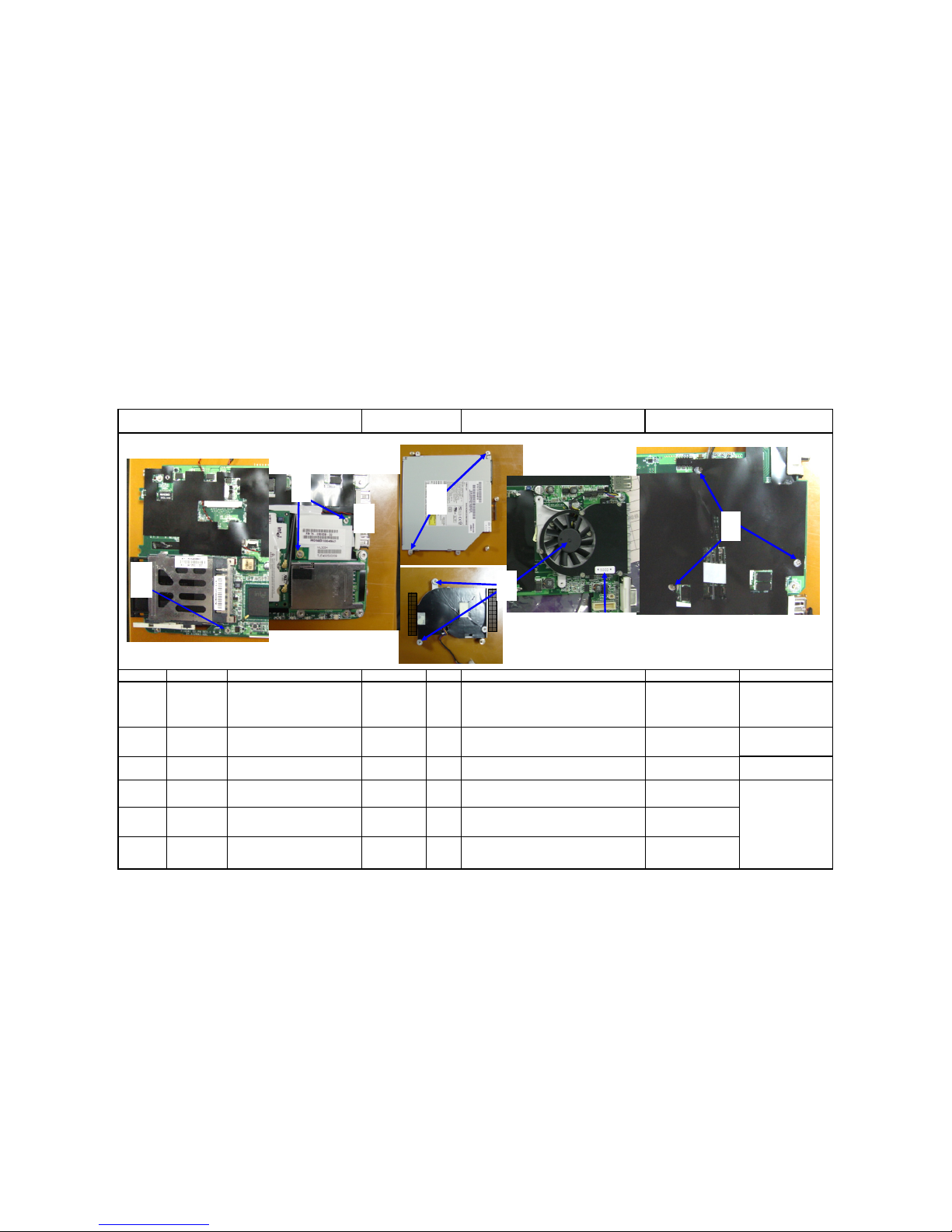
1 F10DA1-HEATSINK W/FAN-F4218 40-003650-01 1
Check the appearance of Heat Sink Module and ensure the
heat radiating blade is free of bruise. Place the fan on the jig
and put the left-side screw right above two support poles in
place.
Do not pinch the wries and do
not press the blade of the
portable fan.
Support jig.
2 DATE CODE LABEL(month label) 63-000041-XX
1
Attach the month label on the fan onto the position shown
as per the figure.
NA NA
3 ODD ASS'Y NA
1
Place the ODD on the support jig and fix with two
positioning poles in place.
NA Support jig.
4
SCREW ISOT-M2X3L-SELFLOCKINGD3.5mm t=0.8mm-B4424H
41-721520-03 3
Place the M/B on the support jig and then lock three screws
to fix the fan by a-b-c sequence.
NA
5
SCREW ISOT-M2X3L-SELFLOCKINGD3.5mm t=0.8mm-B4424H
41-721520-03 2
Lock two screws to fix the ODD on the M/B, as per the
figure.
NA
6
SCREW ISOT-M2X3L-SELF-LOCKING
∮D3.5mm t=0.8mm-B4424H
41-721520-03 2
Assemble the Modem on the M/B and then lock two screw
to fix the Modem by a-b sequence, as per the figure.
NA
Explanation for illustration
PAGE:04
Electrical
Screwdriver/Torque: 1.5±
0.2Kgf-cm
Twinhead S.O.P Document NO:TESOP587
Manufacturing Section: PE
Date: 2005.04.18
Working name:7003
Name of S.O.P﹕F10DA System Ass'y SOP
Tw inhead International (Kunshan) CO.,LTD
Tw inhead
4
a
b
c
2
6
5
1
3
b
28
Page 31

Revision:0
Difference Operating Item Part name / Specification
Parts Number Q'TY Operation Description Important Note
Jig / Fixture
1NA NA NA
Fix the magnetic fastener near the port in the gap
located on the right side at the center of USB
connection port, and then insert the fan wires into the
M/B connection port. Connect the lower connection
port of ODD harness to the M/B and then stripping
the back-glue paper for attaching the harness on the
ODD, as per the figure.
Keep the wires from loosening or
lifting.
NA
2
ALL MODEL-INSULATING
TAPE-10mmX66m,T=0.5mm
27-309090-00 4
Trim the Modem wires and fix them with four tapes,
as per the figure.
The Modem wire should evde the
parts wires on the M/B.
Tape stand
W/BLUE
TOOTH
F10DA1-WLAN/BLUETOOTH
W/CABLE-F4262
22-600153-00
W/O BLUE
TOOTH
WLAN W/CABLE-F4371-F10DA1 22-600154-00
ALL MODEL-INSULATING
TAPE-10mmX66m,T=0.5mm
27-309090-00 3
The wires should attach securely
on the M/B side-by-side and should
not be placed above the parts.
Tape stand
Attach when the
screw position in
the center of base
is deformed.
4
F10DA1-MYLAROD5xID3xT0.4mm-F4394
50+023672+00 1
Attach one piece of Mylar on the screw hole of the
M/B, as per the figure.
The Mylar shall align with the
screw hole.
NA
3
1
Keep the antenna port from
loosening.
NA
Connect antennas to the radio transmission small
card, with black antenna going to the connection port
under the small card and the gray one to the upper
connection port. Connect the gray wire of Bluetooth
to the lowest connection port for assembling WLAN
on the M/B, as per the figure. Trim the radio
transmission wires as per the figure and fix them with
three tapes on the M/B, as per the figure.
Explanation for illustration
PAGE:05
Twinhead S.O.P Document NO :TESOP587
Name of S.O.P﹕F9DA System Ass'y SOP Working name:7004
Manufacturing Section:PE
Date: 2005.04.18
Tw inhead International (Kunshan) CO.,LTD
Twinhead
Do not trim the wires
here, and the wires should
not be locatd above the
The wires here should wind around
the parts wires, and the wires should
be kept from lifting.
4
1
2
3
The turning corner of
WLAN metal cover shall
be attached with tape to
separate with the
29
Page 32

Revision:0
Difference Operating Item
Part name / Specification
Parts Number Q'TY Operation Description Important Note
Jig / Fixture
F10DA1-#8160 UPPER COVER
ASS'Y-E1188-06
50-967701-22 1 NA NA
2 F10DA1-MYLAR FOR MB-F4318 50+023639+00 1 Attach the M/B Mylar onto the M/B, as per the figure.
The Mylar should be square
without slanting and the position
of screw hole should be aligned
properly.
NA
3
F10DA1-GASKET FOR VGA PORTF4373
51+035090+01 1
Attach one piece of conductor pad onto the VGA
terminal port, as per the figure.
NA NA
4NA NA 1
Trim the speaker wires into the gap on the right side of
USB connection port for connecting to that on the M/B,
and then assemble the M/B and the Upper Cover.
The M/B should be placed on
the Upper Cover smoothly
without lifting.
NA
Date: 2005.04.18
Barcode MachineNA
DISPLAY ASS'Y-10.6" WXGA TFT
1
1
The LCD spindle must be
assembled in place, and the screw
holes on the spindle must align
with those on the Upper Cover.
Twinhead S.O.P Document NO :TESOP587
Name of S.O.P﹕F9DA System Ass'y SOP Working name:7005
Manufacturing Section:PE
Explanation for illustration
PAGE:06
Attach one piece of machine serial number on the LCD
protection film, verify the barcode and check to make
sure the tape on the Touch Pad is not loosening.
Penetrate teh LCD harness and antenna wires through
the spindle hole on the right side of Upper Cover for
assembling the Upper Cover on the LCD Module, and
then trim the LCD harness and antenna wires according
to the position shown in the figure.
Tw inhead International (Kunshan) CO.,LTD
Tw inhead
2
The lower part of conductor pad on the Mylar at the CRT connection port
must be attched properly to flush with the left and right side of the
connection port.
1
4
3
30
Page 33

Revision:0
Difference Operating Item
Part name / Specification
Parts Number Q'TY Operation Description Important Note
Jig / Fixture
1
SCREW ISOT-M2X3L-SELFLOCKINGD3.5mm t=0.8mm-B4424H
41-721520-03 2
Lock two screws to fix the left and right sides of M/B on the
Upper Cover, as per the figure. The left side screw should be
locked to the M/B together with the iron ring on the LCD
harness.
The conductor pad shall not contact
with the parts on the M/B.
Electrical
Screwdriver/Torque:
1.5±0.2Kgf-cm
2
NA
NA 2
Connect the Modem. Insert the left and right switch push key
wires in the M/B connection ports, and them trim the Power
Bottom PCB wire according to the position shown in the
figure.
NA
NA
3 F10DA1-RJ11/RJ45 CABLE-CA364 29-005364-01 1
Insert RJ11/RJ45 wires into the M/B connection port, and
then connect the external connection port of RJ11/RJ45 to
the position on the Upper Cover as per the figure.
NA NA
4 Acetic tape (approx. 4cm long) NA 2
Trim the RJ11/RJ45 wires as per the figure and the fix with
tape.
NA
Tape stand
Explanation for illustration
PAGE:07
Date: 2005.04.18
Twinhead S.O.P Document NO :TESOP587
Name of S.O.P﹕F9DA System Ass'y SOP
Working name:7006
Manufacturing Section:PE
3
Tw inhead International (Kunshan) CO.,LTD
Tw inhead
1
2
4
31
Page 34

Revision:0
Difference Operating Item
Part name / Specification
Parts Number Q'TY Operation Description Important Note
Jig / Fixture
1
F10DA1-PCB ASS'Y-GU-DC IN-REV:A
80-A12100-00A 1
NA
NA
2
ALL MODEL-KAPTON10mmX33m,T=0.07mm
27-319060-00 1 NA Tape stand
3
F10DA1-CABLE FOR DC IN-CA367 29-005367-00 1 NA NA
4
SCREW ISOT-M2X3L-SELFLOCKINGD3.5mm t=0.8mm-B4424H
41-721520-03 1 Lock the screw to fix the DC small card, as per the figure. NA
Electrical
Screwdriver/Torque:
1.5±0.2Kgf-cm
5
NA NA NA
Trim the DC smaller card wires in these three positioning
poles on the Upper Cover located of the M/B panel edge.
Keep the wires from lifting. NA
Explanation for illustration
PAGE:08
Check the appearance of DC power small card. Wrap the
metallic pin on the rigth side of DC smaller card with a
yellow static tape as per the figure and then assemble the
small card wires in the smaller card, as per the figure. After
assembling smaller card on the upper left corner of the
Upper Cover, trim the wires of smaller card connection port
as per the figure.
Date: 2005.04.18
Twinhead S.O.P Document NO :TESOP587
Name of S.O.P﹕F9DA System Ass'y SOP Working name:7007
Manufacturing Section:PE
Tw inhead International (Kunshan) CO.,LTD
Tw inhead
4
3
Push the head section of
harness downward,
makin
g
it become 9
0
5
1
2
32
Page 35

Revision:0
Difference Operating Item
Part name / Specification
Parts Number Q'TY Operation Description Important Note
Jig / Fixture
1NA NA NA
Connect the LCD harness in the M/B connection port,
and trim the harness as per the figure.
Do not let the LCD harness lift
as to exceed the plane on the
upper screw BOSS pole.
NA
W/BLUE
TOOTH
F10DA1-WLAN/BLUETOOTH
W/CABLE-F4262
22-600153-00
W/O BLUE
TOOTH
WLAN W/CABLE-F4371-F10DA1 22-600154-00
SCREW ISOT-M2X3L-SELF-LOCK
INGD3.5mm t=0.8mm-B4424H
41-721520-03
NA
4NA NA NA
Connect the LCD radio transmission wire to the
corresponding connection port of the radio transmission
smaller panel. Connect the wires of same color, with
gray wire pressing the radio transmission wire at the
upper left corner, while pushing the black wires in the
lower gap. If the Bluetooth function is provided, connect
the Bluetooth wire to the connection port at the upper
right corner of smaller panel as per the figure. Push the
wires in the lower gap.
Do not let the wire connection
port loosen or lift, and short
connection of head is not
allowed.
NA
PAGE:09
21
NA
NA
Check the appearance of radio transmission wire and
place the smaller panel on the Upper Cover, and then
lock the screw to fix the smaller panel as per the figure.
Trim the radio transmission wire and push the lower
radio transmission wire in the lower positio before the
LCD harness, and then arrange excessive wires to the
upper left corner.
31
Manual
Screwdriver/Torque: 0.5±
0.2Kgf-cm
Twinhead S.O.P Document NO:TESOP587
Name of S.O.P﹕F9DA System Ass'y SOP Working name:7008
Manufacturing Section:PE
Date: 2005.04.18
Explanation for illustration
Tw inhead International (Kunshan) CO.,LTD
Tw inhead
Radio transmission connection
port when the Bluetooth
function is provided.
3
1
2
4
33
Page 36

Revision:0
Difference Operating Item Part name / Specification
Parts Number Q'TY Operation Description
Important Note Jig / Fixture
HDD ASS'Y NA 1 NA NA
PRODUCT BAR CORD LABEL 63-000710-00 1 NA Barcode Machine
2
F10DA1-HDD SPONGE-30X8X4mmBLACK-F4301
51+036301+00 1
Assemble the HDD Sponge on the left end
connection port between HDD and M/B, as per the
figure.
The upper surface of HDD Sponge
cannot be higher then that of the
HDD, and the lower part cannot block
the lower screw hole.
NA
3
NA
NA 1
The speaker wire connnection port must be
connected to the M/B connection port, and then
arrange excessive wires in the gap above he
connection port as per the figure.
Keep the wires from lifting.
NA
4
CONDUCTIVE SPONGE-KL1788G
10X10.5X7mm
51-350094-08 2
Stick one piece of conductor foam on these two
USB ports respectively.
Be square without floating. NA
PAGE:10
Twinhead S.O.P Document NO :TESOP587
Name of S.O.P﹕F9DA System Ass'y SOP
Working name:7009
Manufacturing Section:PE
Date: 2005.04.18
Check the appearance of HDD and attach the
machine serial number on the HDD. Verify the
Barcode and assemble the HDD on the M/B as per
the figure.
1
Explanation for illustration
Tw inhead International (Kunshan) CO.,LTD
Tw inhead
2
1
3
4
34
Page 37

Revision:0
Difference Operating Item
Part name / Specification
Parts Number Q'TY Operation Description
Important Note
Jig / Fixture
1
F10DA1-WIRELESS KNOB-#8162F4232
50-041121-00 1
Assemble the radio transmission switch on the M/B, as per
the figure.
NA NA
2
F10DA1-LOWER COVER-#8162-MB1377
40-002522-01 1
Check that the appearance of the Lower Cover is free
of scratch or stains. To assemble the base on the
Upper Cover, install the base from the left side
connection port and then put down the right side of
the base.
Do not take or press the cross
beam of PCMCIA and ODD and
the weak part of battery slot, and
check that both areas are free of
deformation and breaking. During
assembling, do not push down too
hard.
NA
3
SCREW ISOTT-M2X8L,∮D4.0,H0.8SELF LOCKING-B3516Z
41-760520-08 5
Lock five screws to fix the Lower Cover by a.b.c.d.e
sequence, as per the figure.
NA
Electrical
Screwdriver/Torque:
2.0±0.2Kgf-cm
Explanation for illustration
PAGE:11
Twinhead S.O.P Document NO :TESOP587
Name of S.O.P﹕F9DA System Ass'y SOP
Working name:7010
Manufacturing Section:PE
Date: 2005.04.18
Tw inhead International (Kunshan) CO.,LTD
Tw inhead
a
3
a
b
c
d
e
2
1
Wires should not be seen
from here.
35
Page 38

Revision:0
Difference Operating Item
Part name / Specification
Parts Number Q'TY Operation Description
Important Note
Jig / Fixture
1
F10DA1-#8160 SPEAKER COVER
ASS'Y-E1118-05
50-967701-32 1
Check the appearance of Speaker Cover and then
assemble it in the machine, as per the figure.
The anti-dust sponge shall be free
of foreign matters. Assemble the
sponge from the external latch of
the upper part.
NA
2
SCREW ISOT-M2X6L-NI+NYLOK #1
I ∮D=3.4mmH=0.8mm-B4424H
41-721520-06 3
Lock three screws to fix the Speaker Cover, as per the
figure.
NA
3
SCREW ISOT-M1.6X4L,∮D3.0,H0.8NI-SELF-LOCKING-B3516
41+720516+04 2
Lock two screws to fix the cross beam connection between
Upper Cover and Lower Cover, as per the figure.
Check that the connection part is
free of deformation.
Explanation for illustration
PAGE:12
Electrical
Screwdriver/Torque: 1.5±
0.2Kgf-cm
Date: 2005.04.18
Twinhead S.O.P Document NO :TESOP587
Name of S.O.P﹕F9DA System Ass'y SOP
Working name:7011
Manufacturing Section:PE
Tw inhead International (Kunshan) CO.,LTD
Tw inhead
2
1
3
36
Page 39

Revision:0
Difference Operating Item
Part name / Specification
Parts Number Q'TY Operation Description
Important Note
Jig / Fixture
1
SCREW ISOT-M2.6X5L,∮
D4.5,H0.8-NI-SELF-LOCKINGB3516Z
41-722526-05 2
Lock two screws to fix the LCD spindle at the bottom, as
per the figure.
NA
2
SCREW ISOT-M2.6X5L,∮
D4.5,H0.8-NI-SELF-LOCKINGB3516Z
41-722526-05 2 Lock two screws to fix the LCD spindle at the rear side. NA
3 PRODUCT BAR CORD LABEL 63-000710-00 1 Stick one piece of machien serial number in the battery s
l
NA NA
Explanation for illustration
PAGE:13
Support jig
Electrical
Screwdriver/Torque: 3.5
±0.2Kgf-cm
Date: 2005.04.18
Twinhead S.O.P Document NO :TESOP587
Name of S.O.P﹕F9DA System Ass'y SOP Working name:7012
Manufacturing Section:PE
Tw inhead International (Kunshan) CO.,LTD
Tw inhead
2
1
3
37
Page 40

Revision:0
Difference Operating Item
Part name / Specification
Parts Number Q'TY Operation Description
Important Note
Jig / Fixture
K/B-83 KEY-EN-11015# WHITEF10DA1-K022309A1 US-JME
71-836101-00
K/B-83 KEY-ZH-W01011# WHITEF10DA1-K022309A1 CH-JME
71+836102+00
K/B-83 KEY-KO-W01011# WHITEF10DA1-K022309A1 KR-JME
71+836104+00
K/B-83 KEY-FR-W01011# WHITEF10DA1-K022309A1 FR-JME
71+836105+00
K/B-83 KEY-DE-W01011# WHITEF10DA1-K022309A1 GR-JME
71+836107+00
K/B-83 KEY-XZ-W01011# WHITEF10DA1-K022309A1 UK-JME
71+836108+00
K/B-83 KEY-XD-W01011# WHITEF10DA1-K022309A1 CF-JME
71+836129+00
2 KEY PARTS LABEL 63-250190-00 1
The sticker cannot block the
bigger hole on the K/B.
Barcode Machine
3NA NA 1
Open the LCD and align the Touch Pad wire with the slot in the
connection port of M/B and then fix, as per the figure.
Before opening the LCD, be sure
to confirm that four screws of
the spindle are tightly locked.
Wire connection jig.
4NA NA NA
Connect the K/B wires to the M/B connection port in place. Fix
the K/B in these three latches located at the upper part of Upper
Cover, as per the figure.
The K/B must be push into the
latch at upper part of Upper
cover, and the K/B should be
kept from loosening.
NA
Date: 2005.04.18
Twinhead S.O.P Document NO :TESOP587
Name of S.O.P﹕F9DA System Ass'y SOP Working name:7013
Manufacturing Section:PE
Check the appearance of K/B and stick Key Parts Label on the
K/B, and then verify the Barcode.
Explanation for illustration
PAGE:14
11
The typeface printing of the K/B
should not be smeared.
NA
Tw inhead International (Kunshan) CO.,LTD
Tw inhead
2
1
4
4
38
Page 41

Revision:0
Difference Operating Item
Part name / Specification
Parts Number Q'TY Operation Description
Important Note
Jig / Fixture
Quanta ODD
assembly.
F10DA1-QUANTA COMBO
TRANSFER BEZEL-F4230
50-000483-00
Hitachi-LG
ODD assembly
F10DA1-HLDS COMBO TRANSFER
BEZEL-#8162-F4294
50+000485+00
Quanta ODD
assembly.
F10DA1-#8162 COMBO BEZEL
ASS'Y-FOR QUANTA-E1118-03
50-967701-62
Hitachi-LG
ODD assembly
F10DA1-#8162 COMBO BEZEL
ASS'Y-FOR HITACHI-LG
50+967701+71
3
SCREW ISOTT-M1.2X3L,∮
D3.0,H0.3 -NI-SELF-LOCKINGB3516
41+760512+03 2 Lock two screws to fix the ODD Bezel, as per the figure. NA
Electrical
Screwdriver/Torque:
1.5±0.2Kgf-cm
4
SCREW ISOT-M2.6X5L,∮D4.5,H0.8NI-SELF-LOCKING-B3516Z
41-760520-08 1
Lock the K/B on the base with the screws shown in the
figure.
NA
5
SCREW ISOT (LCD COVER)-M3X4L
∮5.3mm-HEAT TREMENT+NI
PLATING-SELF-LOCKING-B3516Z
41-720530-04 4
Lock four screws to fix the HDD on the Lower Cover by
a.b.c.d sequence, as per the figure.
NA
2
1
1
Assemble the Combo Bezel on the ODD tray and then
assemble the Combo Bezel Ass'y on the ODD Combo
Bezel, as per the figure.
Twinhead S.O.P Document NO :TESOP587
Name of S.O.P﹕F9DA System Ass'y SOP
Working name:7014
Manufacturing Section:PE
PAGE:15
1
Date: 2005.04.18
Explanation for illustration
Check if the Bezel material
number is correct, if the bezel is
consistent with the body and if
the Bezel is deformed. The screw
holes must be aligned.
NA
Electrical
Screwdriver/Torque:
1.5±0.2Kgf-cm
Tw inhead International (Kunshan) CO.,LTD
Tw inhead
5
a
b
c
d
4
2
3
1
39
Page 42

Revision:0
PAGE:16
Twinhead S.O.P Document NO :TESOP587
Name of S.O.P﹕F9DA System Ass'y SOP
Working name:7015
Manufacturing Section:PE
Date: 2005.04.18
Explanation for illustration
Tw inhead International (Kunshan) CO.,LTD
Tw inhead
Gap between LCD
Module and Hinge Cap:
Less than 1.2mm
Gap between LCD Module and
Base: Less than 1.7mm
(1) Gap between LCD
and panel: Less than
0.8mm.
Gap of four corner of LCD
Module: Less than 0.8mm
Gap between Lower
Cover and Bezel: Less
than 1.0mm
Upper cover and Bezel:
Gap: Less than 1.0mm
STEP: Less than 0.3mm
Upper cover and battery:
DEEP: Less than 0.3mm
GAP: Less than 0.8mm
Gap between ODD Bezel and
lower cover: Less than 1.4mm.
Gap between battery
and lower cover: Less
than 0.8mm
BATTERY and LOWER
COVER Gap=<0.8mm
Finish line of four sides:
Gap: Less than 0.8mm
Step: Less than 0.5mm
Finish line of four sides:
Gap: Less than 0.8mm
Step: Less than 0.5mm
Gap between upper and lower
covers: Less than 0.8mm.
Gap between LCD
Module and Hinge Cap:
Less than 1.2mm
Gap around the
push key: Less
than 0.3mm.
2
4
5
6
3
1
7
40
Page 43

Revision:0
Difference Operating Item
Part name / Specification
Parts Number Q'TY Operation Description
Important Note
Jig / Fixture
W/INTEL ID
F10DA1-FCC RATING LABEL-ENFOR INTEL ID-F4358
63+040280+20
KO
F10DA1-FCC RATING LABEL-KOF4358
63+040280+10
W/MSI ID
F10DA1-FCC RATING LABEL-ENFOR MSI ID-F4358
63+040280+30
PAGE:17
Twinhead S.O.P Document NO:TESOP587
Name of S.O.P﹕F10DA System Ass'y SOP Working name:7016
Manufacturing Section: PE
Date: 2005.04.18
Explanation for illustration
11
Attach the FCC Label onto the base according to the
position shown in the figure.
NABe square without floating.
Tw inhead International (Kunshan)
Tw inhead
1
41
Page 44

Twinhead International (Kunshan) CO.,LTD
REVISION: 0
PREPARED BY
CONCURRED
BY
APPROVED BY
1. NEW RELEASE PE: Li, Shin Prepared by:
QC:
Twinhead
F10DA 10.6" LEC Pre-Assembly SOP
DOCUMENT CODE:TESOP586
RELEASE DATE:
PAGE: 11 (total 13 pages)
DESCRIPTION
42
Page 45

Page No. /Revision No. List:
Page No. Rev. No. Page No. Rev. No. Page No.Rev. No.Page No
.
Rev. No.
1. Table of Contents P.01 1 0
2. Machine Assembly Material List/Operation Instrutions/Illustrations P.02~P.11 2 0
(Work number: 11 persons, including test) 2-1 0
3. References 3 0
1. Plastics Injection Inspection Rules (see D/C No.: KE3-0113) 4 0
2. Electrical Screwdriver Operation Standard (see D/C No.:KE3-0010) 5 0
3. Appearance Inspection Specification KE3-0058. 6 0
4. Tools used: Electrical screwdriver, tape stand. 7 0
80
90
10 0
11 0
Actual material shall be selected according to BOM.
REV: 0
Document NO.:TESOP586
This SOP is applicable for F10DA 10.6" LCD Samsung, Sharp LCD Assembly.
Table of Contents/Manpower Distribution Chart for F10DA 10.6" LCD Assembly SOP
PAGE:01
Twinhead International (Kunshan) CO.,LTD
Twinhea
d
43
Page 46

Revision:0 Manufacturing Section:PE
Date:2005.04.18
Difference Operating Item Part name / Specification Parts Number Q'TY Operation Description Important Note Jig / Fixture
F10DA1-#8561-M LCD COVER ASS'Y-FOR
SHARP-E1118-01
40-967701-03
F10DA1-#8167-M LCD COVER ASS'Y-FOR
SHARP-E1118-01 (pearly white)
40-967701-91
F10DA1-#8466-M LCD COVER ASS'Y-FOR
SHARP-E1118-01
40-967701-72
F10DA1-#8561-M LCD COVER ASS'Y-FOR
SAMSUNG-E1118-02
40-967701-13
F10DA1-#8167-M LCD COVER ASS'Y-FOR
SAMSUNG-E1118-02 (pearly white)
40-967701-A1
F10DA1-#8568-M LCD COVER ASS'Y-FOR
SAMSUNG-E1118-02 (dark blue)
40-967701-B1
F10DA1-#8369-M LCD COVER ASS'Y-FOR
SAMSUNG-E1118-02
40-967701-C0
F10DA1-#8470-M LCD COVER ASS'Y-FOR
SAMSUNG-E1118-02
40-967701-D0
F10DA1-#8471-M LCD COVER ASS'Y-FOR
SAMSUNG-E1118-02
40-967701-E0
F10DA1-#8972-M LCD COVER ASS'Y-FOR
SAMSUNG-E1118-02
40-967701-F0
F10DA1-#8162-M LCD COVER ASS'Y-FOR
SAMSUNG-E1118-02
40-967701-G0
F10DA1-#8472-M LCD COVER ASS'Y-FOR
SAMSUNG-E1118-02
40-967701-H0
F10DA1-#8466-M LCD COVER ASS'Y-FOR
SAMSUNG-E1118-02
40-967701-82
2 F10DA1-ANTENNA-L-D3058 22-600151-00 1
3 F10DA1-ANTENNA-R-D3057 22-600150-00 1
PAGE: 02
NA
Strip the adhesive tape from the backside of left
and right antennas and assemble them on the
LCD cover, with conducting pad attached to
LCD cover securely.
The conducting pad
must be attached flat
and the antenna screw
holes must be aligned.
Twinhead S.O.P Document NO.:TESOP586
Name of SOP:F10DA 10.6" LCD MODULE ASS'Y SOP
Working name:6512-1
NA NA
Explanation for illustration
1
Check the appearance and no bruise or stain
damage is allowed.
1
SHARP LCD
Assembly
SAMSUNG
LCD
Assembly
Twinhead International (Kunshan) CO.,LTD
Twinhead
3
2
44
Page 47

Revision:0 Manufacturing Section:PE
Date:2005.04.18
Difference Operating Item Part name / Specification Parts Number Q'TY Operation Description Important Note Jig / Fixture
1NA NA 1
Check the appearance of "AVERATEC" logo on
the LCD cover. Press the internal Logo with a jig
along the slot lightly, sticking it in the slot. If the
adhesion of Logo is poor, pick the defective one
and replace new Logo.
The Logo should be
kept from lifting.
Jig
PAGE: 02-1
Explanation for illustration
Twinhead S.O.P Document NO.:TESOP586
Name of SOP:F10DA 10.6" LCD MODULE ASS'Y SOP
Working name:6512-1-1
Twinhead International (Kunshan) CO.,LTD
Twinhead
1
45
Page 48

Revision:0 Manufacturing Section:PE
Date:2005.04.18
Difference Operating Item Part name / Specification Parts Number Q'TY Operation Description Important Note Jig/Fixture
LCD-10.6" TFT WXGA-SAMSUNGLTN106W2-L01
72-11026S-00
LCD-10.6" TFT WXGA-SAMSUNGLTN106W2-L01-TRIGEM CSG
72-11026S-00TRI
SHARP LCD
LCD-10.6" TFT WXGA-SHARPLQ106K1LA01A
72-11023J-00
SAMSUNG LCD
F10DA1-HARNESS FOR SAMSUNG LCDSH773
29-001773-01
Watch the lead-out
position, as per the figure.
Harness positioning
jig.
SHARP LCD
F10DA1-HARNESS FOR SHARP LCDSH772
29-001772-00 NA NA
3
ALL MODEL-INSULATING TAPE20mmX66m.T=0.5mm (broad white tape, 3cm)
27-309091-00 1
Fix the LCD harness end connection port with a
white tape, as per the figure.
4
ALL MODEL-INSULATING TAPE10mmX66m,T=0.5mm(narrow white tape, 5cm)
27-309090-00 1
Fix the lower LCD harness with a tape, as per the
figure.
5 Maker's barcode/keyparts Label NA 2
Verify the LCD maker barcode and attach the produced maker
barcode on the LCD protection film,and then stick the Keyparts
label on the backside of LCD, as per the figure.
NA Barcode machine
PAGE: 03
2 1
Assemble the LCD harness on the LCD port, as per
the figure.
Attach the tape securely
and keep wires from lifting.
Tape stand
Twinhead S.O.P Document NO.:TESOP586
Name of SOP:F10DA 10.6" LCD MODULE ASS'Y SOP
Working name:6512-2
Explanation for illustration
NA11
Do not press the PCB on
the backside of LCD with
hand.
Check the appearance of LCD panel and scratches,
bruise and stain damage are not allowed.
SAMSUNG LCD
Twinhead International (Kunshan) CO.,LTD
Twinhead
5
2
3
4
Keep the lead-out
away from left side for
48mm
1
The SAMSUNG LCD harness shall not
exceed the right side of the upper slot
opening
5
Sharp LCD
attaching
SAMSUNG LCD
attaching position
46
Page 49

Revision:0 Manufacturing Section:PE
Date:2005.04.18
Difference Operating Item Part name / Specification Parts Number Q'TY Operation Description Important Note Jig / Fixture
1
F10DA1-LCD BRACKET-L FOR
SAMSUANG-D3055
40-031653-00 1 NA NA
2
ISOTT SCREW-M2X4L,∮D3.5mm,H-0.5-NISELF-LOCKING-HEAT TREATMENT-B3516
41-761520-04 2 NA
Electrical
Screwdriver/Torque: 1.0±
0.2Kgf-cm
3
F10DA1-LCD BRACKET-R FOR
SAMSUANG-D3054
40-031654-00 1 NA NA
4
ISOTT SCREW-M2X4L,∮D3.5mm,H-0.5-NISELF-LOCKING-HEAT TREATMENT-B3516
41-761520-04 2 NA
Electrical
Screwdriver/Torque: 1.0±
0.2Kgf-cm
5NA NA 1
Allow the upper part of LCD body to contact the
upper part of LCD cover. Tip it slightly and push
upward to the end, and then place it under the
LCD for assemble in the LCD cover.
The screw holes on the iron
frame must align with that on
the LCD cover, and do not let
the upper part of LCD press the
antenna wires.
NA
PAGE: 04
Explanation for illustration
Assemble the right side iron frame of LCD and
then fix two screws tightly.
Assemble the left side iron frame of LCD and
then fix two screws tightly.
SAMSUNG LCD
Assembly
Twinhead S.O.P Document NO.:TESOP586
Name of SOP:F10DA 10.6" LCD MODULE ASS'Y SOP
Working name:6512-2
Twinhead International (Kunshan) CO.,LTD
Twinhead
1
Right side of
LCD
Left side of LCD
2
4
3
47
Page 50

Revision:0 Manufacturing Section:PE
Date:2005.04.18
Difference Operating Item Part name / Specification Parts Number Q'TY Operation Description Important Note Jig / Fixture
INVERTER-5V-SUMIDA-IV10123/T F10D-098 76-030117-00 1
Date Code Label (month label) 63-000041-XX 1
2
ISOTT SCREW-M2X4L,∮D3.5mm,H-0.5-NISELF-LOCKING-HEAT TREATMENT-B3516
41-761520-04 4
Lock screws to fix the LCD in the LCD cover,
as per the figure.
NA
Electrical
screwdriver/Torque:
1.5±0.1Kgf-cm
Twinhead S.O.P Document NO.:TESOP586
Name of SOP:F10DA 10.6" LCD MODULE ASS'Y SOP
Working name:6512-4
PAGE: 05
Description of Illustrations
Strip the backside tape of high-pressure smal
panel and assemble it on the positioning pole at
the LCD cover base, and then stick the month
label on the high-pressure small plate as per the
figure.
NA
The inverter must be assembled
parallel without slanting.
1
Twinhead International (Kunshan) CO.,LTD
Twinhead
Trim the LCD harness downward into
the gap on the left side of LCD cover,
and do not let the wire to lift up.
2
SHARP LCD
SAMSUNG LCD
1
48
Page 51

Revision:0 Manufacturing Section:PE
Date:2005.04.18
Difference Operating Item Part name / Specification Parts Number Q'TY Operation Description Important Note Jig /Fixture
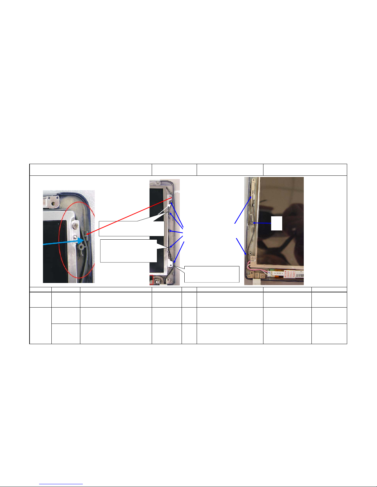
1 F10DA1-HINGE-R-D3050 40-015140-01 1 NA
2
F10DA1-COVER FOR LCD HINGE-R#8160-D3048
50-035294-01 1 NA
3 F10DA1-MYLAR FOR HINGE-R-F4249 50-023634-00 1
Attach Mylar of right spindle on the right spindle, as per
the figure.
Be square without floating . NA
The small hole on the right side
of spindle shall align with the
positioning pole in the Hinge
Cover hole.
PAGE: 06
Explanation for illustration
Twinhead S.O.P Document NO:TESOP586
Name of SOP:F10DA 10.6" LCD MODULE ASS'Y SOP
Working name:6512-5
Check the appearance of right spindle and the cover.
Penetrate the LCD harness and antenna together through
the spindle and right cover holes, and then assemble as
per the figure.
4
SCREW ISOT-M2.6X3L-SELF-LOCKINGB3516Z
41-720526-03
Electrical
Screwdriver/Torque:
2.5±0.2Kgf-cm
2
Lock two screws to fix the LCD spindle, as per the
figure. When locking the left-side screw, press the
conductor pad with hand.
Upon locking the left-side screw of
right spindle, the LCD harness shall
be locked on the spindle together
with the conductor pad. The rightside angle of spindle should be 90
degrees.
Twinhead International (Kunshan) CO.,LTD
Twinhead
1
2
Check the LCD with a jig to set the LCD harness
below the surface of LCD, as per the lower part
marked with red line in the figure.
SAMSUNG LCD wire
SHARP LCD wire
4
Hold the upper part of conductor pad on
the LCD harness with a hand and lock the
screw. The conductor pad must be located
at the position shown in the figure without
slanting.
Before locking the screw in place, check if
this part is 90 degrees. Lock the screw
when it becomes 90 degrees.
3
49
Page 52
Revision:0 Manufacturing Section:PE
Date:2005.04.18
Difference Operating Item Part name / Specification Parts Number Q'TY Operation Description Important Note Jig / Fixture
1NA NA 1
Arrange the wires into the positioning pole
in place, as per the figure, and then pull the
excessive wires from right spindle slowly.
Keep the wire from lifting. Bamboo chopsticks
2 F10DA1-BLUETOOTH ANTENNA-F4246 22-600152-00 1
As per the figure, check the appearance of
Bluetooth antenna and then assemble the
Bluetooth Antenna in the LCD cover.
NA NA
3
ISOTT SCREW-M2X4L,∮D3.5mm,H-0.5-NISELF-LOCKING-HEAT TREATMENTB3516
41-761520-04 1
Lock one screw to fix the Bluetooth antenna,
as per the figure.
NA
Electrical
Screwdriver/Torque:
1.0±0.1Kgf-cm
Twinhead S.O.P Document NO:TESOP586
Explanation for illustration
PAGE: 07
Name of SOP:F10DA 10.6" LCD MODULE ASS'Y SOP
Working name:6512-6
When the
Bluetooth is
used.
Twinhead International (Kunshan) CO.,LTD
Twinhead
Trim the antenna wires in the
gap while keeping them from
lifting up.
The antenna must be trimmed on the
left side of positioning pole in place.
Both antennas must be arranged
in the gap on the right side of
LCD while keeping the wires
from lifting up.
3
1
2
50
Page 53

Revision:0 Manufacturing Section:PE
Date:2005.04.18
Difference Operating Item Part name / Specification Parts Number Q'TY Operation Description Important Note Jig /Fixture
1 F10DA1-HINGE-L-D3049 40-015141-01 1 NA
2
F10DA1-COVER FOR LCD HINGE-L-#8160D3047
50-035295-00 1 NA
3 F10DA1-MYLAR FOR HINGE-L-F4250 50-023633-00 1
Attach the Mylar of left spindle on the spindle as the
position shown in the figure.
The mylar should be attached
squarely without slanting and
floating.
NA
5NA NA 1
Connect the LCD harness to the left and right connection
ports of the Inverter and then arrange the LCD harness and
Bluetooth wires as per the figure.
The wire must be arranged
from the gap above the
Inverter.
NA
6 Acetic tape (approx. 3cm long) NA 2
Attach two pieces of acetic tape to fix the left and right
side of LCD harness, as per the figure.
Keep the wires from
lifting.
NA
Align the small hole on the
left side of spindle with the
positioning pole in the
Hinge Cover.
41-720526-03
Electrical Screwdriver/Torque:
2.5±0.2Kgf-cm
2
Lock two screws to fix the left spindle of LCD, as per the
figure.
Check if the angle of left
side of the spindle is 90
degrees.
PAGE: 08
Explanation for illustration
Twinhead S.O.P Document NO:TESOP586
Name of SOP:F10DA 10.6" LCD MODULE ASS'Y SOP
Working name:6512-7
Check the appearance of left spindle and left spindle
cover and then assemble the cover and the spindle as per
the figure.
4
SCREW ISOT-M2.6X3L-SELF-LOCKINGB3516Z
Twinhead International (Kunshan) CO.,LTD
Twinhead
4
2
1
3
6
5
SAMSUNG LCD wire trimming
Make sure this part be 90 degrees
before locknig the screw in place.
When it becomes vertical, lock the
screw tightly.
51
Page 54

Revision:0 Manufacturing Section:PE
Date:2005.04.18
Difference Operating Item Part name / Specification Parts Number Q'TY Operation Description Important Note Jig / Fixture
1 F10DA1-LCD PANEL-#8160-B1380 50-034120-00 1 NA
2 F10DA1-MAGNET-F4247 27-600050-00 1 NA
3 F10DA1-LCD SPONGE-FOR MAGENTIC-F
4
51-036300-00 1 NA
4 NA NA NA Assemble LCD Panel and LCD Cover. NA NA
5 F10DA1-LCD RUBBER-WHITE-F4238 52-002421-00 1
Attach white LCD Rubber on the upper
part of LCD Panel, as per the figure.
The LCD Rubber be
square without floating.
NA
PAGE: 09
Explanation for illustration
Make sure the LCD Panel is free of
scratch or bruise . Strip the double-face
glue paper from the magnetic stone and
fix it on the left side hole of LCD panel
and then attach one foam on the
surface to cover up the magnetic stone,
as per the figure.
Do not let the magnetic
stone fall.
Twinhead S.O.P Document NO:TESOP586
Name of SOP:F10DA 10.6" LCD MODULE ASS'Y SOP
Working name:6512-8
Twinhead International (Kunshan) CO.,LTD
Twinhead
1
5
2
3
52
Page 55

Revision:0 Manufacturing Section:PE
Date:2005.04.18
Difference Operating Item Part name / Specification Parts Number Q'TY Operation Description Important Note Jig/Fixture
Electrical
Screwdriver/Torque
: 2.0±0.2Kgf-cm
NA
Explanation for illustration
2
F10DA1-RUBBER FOR LCD PANELWHITE-F4239
41-761520-04 4
Twinhead S.O.P Document NO:TESOP586
Name of SOP:F10DA 10.6" LCD MODULE ASS'Y SOP
Working name:6512-9
PAGE: 10
1
52-002420-00 2
Attach two rubber pads on the position at the
upper part of LCD Panel, as per the figure.
Be square without
floating.
ISOTT SCREW-M2X4L,∮D3.5mm,H-0.5NI-SELF-LOCKING-HEAT TREATMENTB3516
NA
Lock four screws to fix the LCD Panel, as per
the figure.
Twinhead International (Kunshan) CO.,LTD
Twinhead
1
2
53
Page 56

Revision:0 Manufacturing Sectoin:PE
Date:2005.04.18
Difference Operating Item Part name / Specification Parts Number Q'TY Operation Description Important Note Jig /Fixture
NA
NANA
Place the assembled LCD in the
protection bag and then load in the carton.
PAGE: 11
NANA
2 NA1NA
Make sure the appearance is free of
scratch,bruise and poor assembly. Place
the protection cotton pad on the LCD
Panel and then cut one piece of LCD
protection film to wrap around the LCD
NA
Explanation for illustration
1
Twinhead S.O.P Document NO:TESOP586
Name of SOP:F10DA 10.6" LCD MODULE ASS'Y SOP
Working name:6512-10
1
Twinhead International (Kunshan) CO.,LTD
Twinhead
1
54
Page 57

55
Page 58

56
Page 59

57
Page 60

58
Page 61

59
 Loading...