

Page 1

All-in-One PC User’s Guide
Space Saving Contemporary Design
Page 2

i
Before You Start
Regulations Information
FCC-B Radio Frequency Interference Statement
This equipment has been tested and found to comply with the limits for a Class B digital device, pursuant to part 15 of the
FCC rules. These limits are designed to provide reasonable protection against harmful interference in a residential
installation. This equipment generates, uses and can radiate radio frequency energy and, if not installed and used in
accordance with the instructions, may cause harmful interference to radio communications. However, there is no
guarantee that interference will not occur in a particular installation. If this equipment does cause harmful interference to
radio or television reception, which can be determined by turning the equipment off and on, the user is encouraged to try
to correct the interference by one or more of the following measures :
• Reorient or relocate the receiving antenna.
• Increase the separation between the equipment and receiver.
• Connect the equipment into an outlet on a circuit different from that to which the receiver is connected.
• Consult the dealer or an experienced radio TV technician for help.
Note
✓ The changes or modifications not expressly approved by the party responsible for compliance could void the user’s authority
to operate the equipment.
✓Shield interface cables and AC power cord, if any must be used in order to comply with the emission limits.
Page 3

ii
Before You Start
FCC RF Radiation Exposure Statement
This equipment complies with FCC RF radiation exposure limits set forth for an uncontrolled environment. This equipment
should be installed and operated with a minimum distance of 20 centimeters between the radiator and your body. This
transmitter must not be co-located or operated in conjunction with any other antenna or transmitter.
FCC Conditions
This device complies with part 15 of the FCC Rules. Operation is subject to the following two conditions :
1. This device may not cause harmful interference.
2. This device must accept any interference received, including interference that may cause undesired operation.
Page 4

iii
Before You Start
Optical Device Drive Notice
Battery Notice
Ethernet Notice
This equipment is indoor use and all the communication wirings are limited to inside of the building.
Power management status
CAUTION
✓This appliance contains a laser system and is classified as a “CLASS 1 LASER PRODUCT.” To use this model properly, read the
instruction manual carefully and keep this manual for your future reference. In case of any trouble with this model, please
contact your nearest “AUTHORIZED service station.” To prevent direct exposure to the laser beam, do not try to open the
enclosure.
CAUTION
✓RISK OF EXPLOSION IF BATTERY IS REPLACED BY AN INCORRECT TYPE. DISPOSE OF USED BATTERIES ACCORDING TO THE
INSTRUCTIONS.
System sleep mode
System Off mode
2.9 W
1.5 W
Without WOL
Without WOL
Page 5

iv
Before You Start
Macrovision Notice
This product incorporates copyright protection technology that is protected by U.S. patents and other intellectual property
rights. Use of this copyright protection technology must be authorized by Macrovision, and is intended for home and other
limited viewing uses only unless otherwise authorized by Macrovision. Reverse engineering or disassembly is prohibited.
Safety Instructions
1. Read the safety instructions carefully and thoroughly.
2. Save this User Guide for possible use later.
3. Keep this equipment away from humidity and high temperature.
4. Lay this equipment on a stable surface before setting it up.
5. The openings on the enclosure are used for air convection and to prevent the equipment from overheating. Do not
cover the openings.
6. Make sure that the power voltage is within its safety range and has been adjusted properly to the value of 100~240V
before connecting the equipment to the power inlet.
7. Place the power cord in a way that people are unlikely to step on it. Do not place anything on the power cord.
8. Always unplug the power cord before inserting any add-on card or module.
9. All cautions and warnings on the equipment should be noted.
Page 6

v
Before You Start
10. If any of the following situations arises, get the equipment checked by a service personnel:
• The power cord or plug is damaged.
• Liquid has penetrated into the equipment.
• The equipment has been exposed to moisture.
• The equipment has not worked well or you can not get it work according to Users Manual.
• The equipment was dropped and damaged.
• The equipment has obvious signs of breakage.
11. Never pour any liquid into the opening that could damage the equipment or cause an electrical shock.
12. Do not leave the equipment in an unconditioned environment with a storage temperature of 60°C (140°F) or above,
which may damage the equipment.
13. To prevent explosion caused by improper battery replacement, use the same or equivalent type of battery
recommended by the manufacturer only.
Page 7

vi
Before You Start
Information about ENERGY STAR
- The ENERGY STAR Computers Program was created by the EPA to promote energy efficiency and reduce air pollution
through more energy-efficient equipment in homes, offices, and factories.
- One way products achieve this is by reducing power consumption when not being used through the Microsoft Windows®
Power Management feature.
- The Power Management feature allows the computer to enter into a low-power or “sleep” mode after a period of user
inactivity.
Trigem computers marked with the ENERGY STAR Logo are compliant with the applicable U.S.
Environmental Protection Agency ENERGY STAR specifications for computers. The EPA ENERGY STAR Logo
does not imply endorsement by the EPA. As an ENERGY STAR Partner, Trigem Computer (AVERATEC) has
determined the products marked with the ENERGY STAR Logo are ENERGY STAR qualified as per the
applicable ENERGY STAR guidelines for energy efficiency.
When used with an external ENERGY STAR compliant monitor, this feature will also support similar power management
features of the monitor. To take advantage of this energy savings:
• The Power Management feature has been preset to power down the computer after 20 minutes of user inactivity.
• The Power Management feature has been preset to power down the monitor after 10 minutes of user inactivity.
• Power Management Status of Product
System Idle Mode
System Sleep Mode
System Off mode
About 34.7 W
2.9 W
1.5 W
Without WOL
Page 8

vii
Before You Start
- Both the computer and monitor can be woken from “sleep” mode through user interaction with any of the computer’s
input devices (ex: mouse, keyboard, etc).
- When configured with Wake On LAN (WOL) enabled, the computer can also be awoken by a network signal.
More information on the energy and financial savings potential of the Power Management Feature can be found at the
EPA’s ENERGY STAR Power Management Web site :
www.energystar.gov/powermanagement<http://www.energystar.gov/powermanagement>
More information on the ENERGY STAR program and its environmental benefits are available by visiting the EPA’s ENERGY
STAR Web site address : www.energystar.gov
Page 9

viii
Before You Start
WEEE Statement
Page 10

ix
Before You Start
Before You Read
The information in this user’s guide is subject to change without notice.
TriGem Computer, Inc. shall not be liable for technical or editorial errors or omissions contained herein; nor for incidental
or consequential damages resulting from the furnishing, performance, or use of this material.
AVERATEC is a trademark or registered trademark of TriGem Computer, Inc. in the United States and/or other countries.
All other product and brand names are trademarks of their respective owners.
©2009 TriGem Computer, Inc. All rights reserved.
Note
✓ Depending on the model, your computer’s components may vary and look slightly different than those pictured.
Release History
Version
1.1
Revision Note
Second Release
Date
05, 2009
Page 11

x
Before You Start
Table of Content
Before You Start
Regulations Information i
Optical Device Drive Notice iii
Battery Notice iii
Ethernet Notice iii
Power management status iii
Macrovision Notice iv
Safety Instructions iv
Information about ENERGY STAR vi
WEEE Statement viii
Before You Read ix
Release History ix
Chapter 1 About your Computer
What is the Averatec All-In-One PC? 1-1
System Overview 1-3
Connecting the Power Cord 1-6
Chapter 2 Setting Up Your Computer
Plugging in Your PC 2-1
Setting Up Windows Vista for the First Time 2-2
Connecting to the Internet 2-7
Chapter 3
Using the Keyboard and Mouse
The Keyboard 3-1
The Mouse 3-4
Chapter 4 Using the Multimedia Features
Using the Optical Drive 4-1
Setting Up and Adjusting the Audio Features 4-3
Using Your Webcam 4-7
Using the Multi-Card Reader 4-10
Setting Up Media Center 4-12
Chapter 5 Adjusting the LCD Screen
Placing the LCD in Standby 5-1
Adjusting the Brightness of the Monitor 5-2
Adjust Screen Resolution 5-3
Page 12

xi
Before You Start
Chapter 6 Using the Optional VESA Mount
Using the Optional VESA Mount 6-1
Chapter 7 System SETUP(BIOS)
Entering Setup 7-1
System Setup Options 7-2
Appendix A Specifications
Specifications and Descriptions A-1
Appendix B Troubleshooting & Support
Troubleshooting B-1
Recovering Your Original Software B-7
Getting Help B-8
Appendix C Glossary
Term & Definitions C-1
Page 13

1
Chapter 1 About your Computer
About your Computer
Chapter
1
Page 14

1-1
Chapter 1 About your Computer
What is the Averatec All-in-One PC?
The Averatec All-in-One PC is an all inclusive desktop PC that is designed for quick installation and easy use without taking
up much desk space.
Features
Integrated PC and LCD monitor
The Averatec All-in-One PC is equipped with a 18.4" wide LCD monitor and fully functional PC. Nothing else is needed.
The All-In-One PC is designed to be a complete plug-and-play system.
Less cabling and more portability
The Averatec All-in-One PC eliminates all those messy cables, enhances system portability and results in less clutter.
Everything’s included!
The Averatec All-in-One PC includes everything necessary to be immediately productive. An industry-leading 18.4" wide
screen LCD monitor coupled with an advanced AMD Dual-core processor to handle all your entertainment and
productivity applications. Additionally, the Averatec All-in-One PC comes with the following features:
• A large hard drive for all your storage requirements.
• A web cam for video chatting, recording and picture taking.
• A full-size keyboard and mouse for ultimate comfort.
Slim CD drive
With a slim CD drive built-in, you can install all your CD or DVD based applications and also watch all your favorite DVD
movies.
Page 15

1-2
Chapter 1 About your Computer
Designed for the Internet
The Averatec All-in-One PC is designed for the Internet, so you can send emails or instant messages, talk to friends over
VoIP or just surf the web with ease.
Efficient computing
The Averatec All-in-One PC is designed to support all your basic computing needs and then some. With this PC, you can
enjoy the most popular tasks such as word processing, internet browsing and basic gaming.
Improved power management
The Averatec All-in-One PC, with it’s AMD based Dual-Core CPU and efficient design, requires very low-power
consumption.
Internal microphone
With the built-in microphone, you can fully enjoy chatting with your friends and family members via one of many on-line
communication applications such as Microsoft MSN or Yahoo’s Messenger.
Page 16

1-3
Chapter 1 About your Computer
System Overview
Front
Integrated webcam
TFT LCD
HDD / CD drive LED
Microphone
Power LED
LCD brightness adjustment
(increase / decrease)
Volume increase
Volume decrease
Power button
LCD ON / OFF
Audio mute
Page 17

1-4
Chapter 1 About your Computer
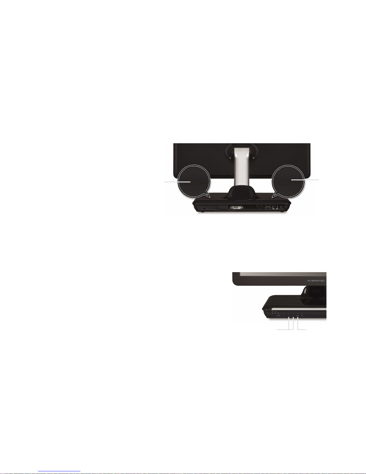
Back
Integrated speakers
Cooling vents
DVI - I connector
e-SATA & USB connector
DC-IN connector
RJ45 / LAN connector
USB connector
Integrated speakers
Page 18

1-5
Chapter 1 About your Computer
Left Right
USB connector
CD/DVD eject button
Slim tray-loading CD drive
(COMBO / SuperMulti DVD)
Microphone / Headphone jack
Card reader slot
Page 19

1-6
Chapter 1 About your Computer
Connecting the Power Cord
Plug the power cord into the AC power receptacle on the back panel. Then plug the other end of the power cord into an
appropriate grounded electrical outlet.
Warning
✓ To avoid generating an electric shock. be sure to plug the cord into the system before plugging it into the wall socket.
Caution
✓ For protection of your computer and other devices during a lightning storm, or when it is left unattended and unused for
long periods of time, unplug the computer and other devicess from the wall outlet and disconnect the antenna or cable
system. This will prevent damage to the computer and other devices due to lighting and power line surges.
Page 20

2
Chapter 2 Setting Up Your Computer
Setting Up Your Computer
Chapter
2
Page 21

2-1
Chapter 2 Setting Up Your Computer
Plugging in Your PC
Connecting the USB devices
If you have the USB devices, you can connect these to the USB connectors. To connect a USB device to the USB connector,
plug the USB device cable connector into the USB connector of your system.
Note
✓ If you are using only one connector, use the most convenient connector for you.
Page 22

2-2
Chapter 2 Setting Up Your Computer
Setting Up Windows Vista for the First Time
If you are starting Windows Vista for the first time, you have to complete Windows Vista set up and registration.
To set up your computer, follow the next steps:
1. Turn on your peripheral devices connected to your computer and press
the power button on your system.
2. The process of setting up your computer will be loaded.
3. Choose your country or region, time and currency, and keyboard layout,
and then click Next.
Page 23

2-3
Chapter 2 Setting Up Your Computer
4. Read the Microsoft license terms, check the I accept the license terms option,
and click Next.
5. Type your user name and password, choose your user account picture, and then
click Next.
6. Type your computer name, choose a computer background, and then click Next.
Page 24

2-4
Chapter 2 Setting Up Your Computer
8. Choose your time and date settings and click Next.
9. Click Start.
7. You can select automatic updates for Windows to help keep your computer up-todate. Click Use recommended settings.
Page 25

2-5
Chapter 2 Setting Up Your Computer
10. Please wait during checking of your computer’s configuration. Please be prepared to wait as this process may take
some time to complete.
11. Input the password if you set up the password during registration and press Enter.
12. Windows Vista desktop appears and Welcome Center automatically appears when the computer is started for the first
time.
Page 26

2-6
Chapter 2 Setting Up Your Computer
Note
✓
Turning off
Case 1
Click Start to turn off computer.
Click start and select
Shut Down. Turn off computer screen displays.
Case 2
Press the power button on the front of the PC.
After closing all programs, the PC will be turned off. If the system is
operating abnormally, you can reboot the PC by holding down the
Power button until the PC turns off. Then press the Power button
again to boot back up.
Case 3
Power saving mode.
Saves your session and puts the computer in a lower-power state so that you can
quickly resume working.
Page 27

2-7
Chapter 2 Setting Up Your Computer
Connect to the LAN
1. Press the power button and the Windows Vista start screen will appear.
Connect a LAN cable to the LAN connector as shown in the figure below.
2. Configure the communication settings for the system based on your
communication environment. When connecting to the Internet via an
internet service provider, contact the service provider for more
information on required communication settings.
Connecting to the Internet
3. Launch Internet Explorer or other communication software.
Page 28
2-8
Chapter 2 Setting Up Your Computer
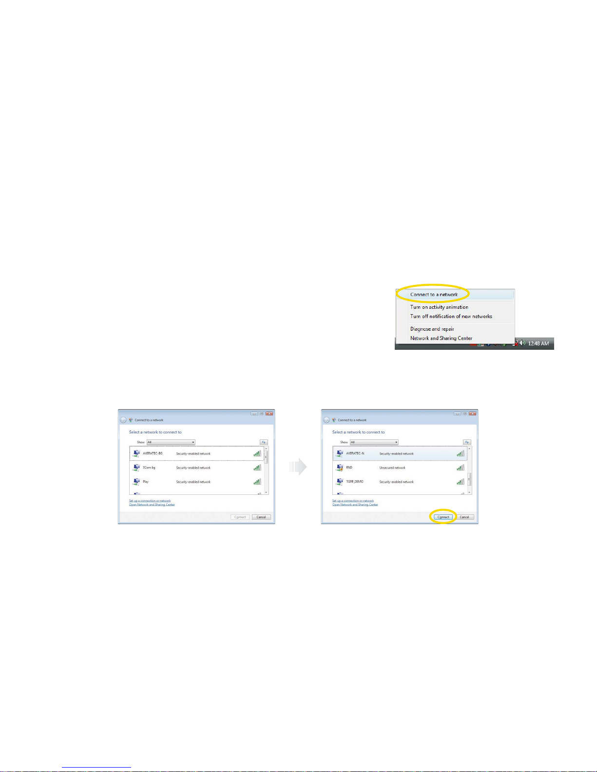
2. If there is an AP-enabled environment, a list of available APs will appear. Click the item you want to connect to, and click
Connect.
1. Right-click on theWireless Network icon on the status bar, and then select
Connect to a network.
Using the Wireless LAN
To use a wireless network in an office environment where APs (Access Points) are installed, see the following instructions.
(The example used here explains how to use the basic Windows configuration features to configure the system. You can also
use the program that comes with the wireless LAN card to configure the network.)
Page 29
2-9
Chapter 2 Setting Up Your Computer
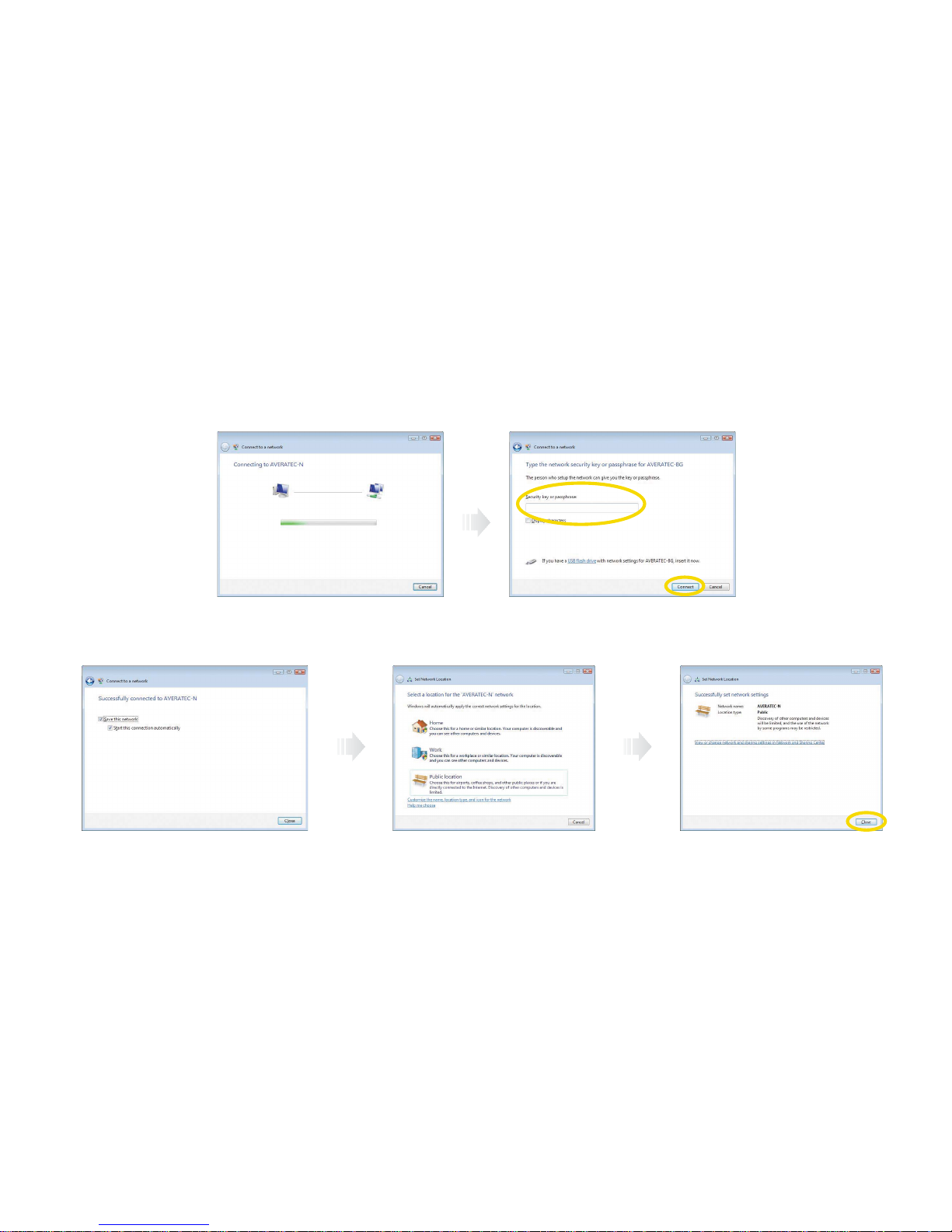
3. A window will appear displaying Connecting to xxxxx (Where XXXXX is the name of your router/AP). If a Security key
or password is set up, a window will appear where you can enter the security key or password. Enter the security key or
password, and click Connect. (The window will not appear if no security key or password is set up.)
4. When the Successfully connected to xxxxx window appears, confirm the settings and then click Close.
Select the right items for your
environment, and click Close.
Page 30
2-10
Chapter 2 Setting Up Your Computer
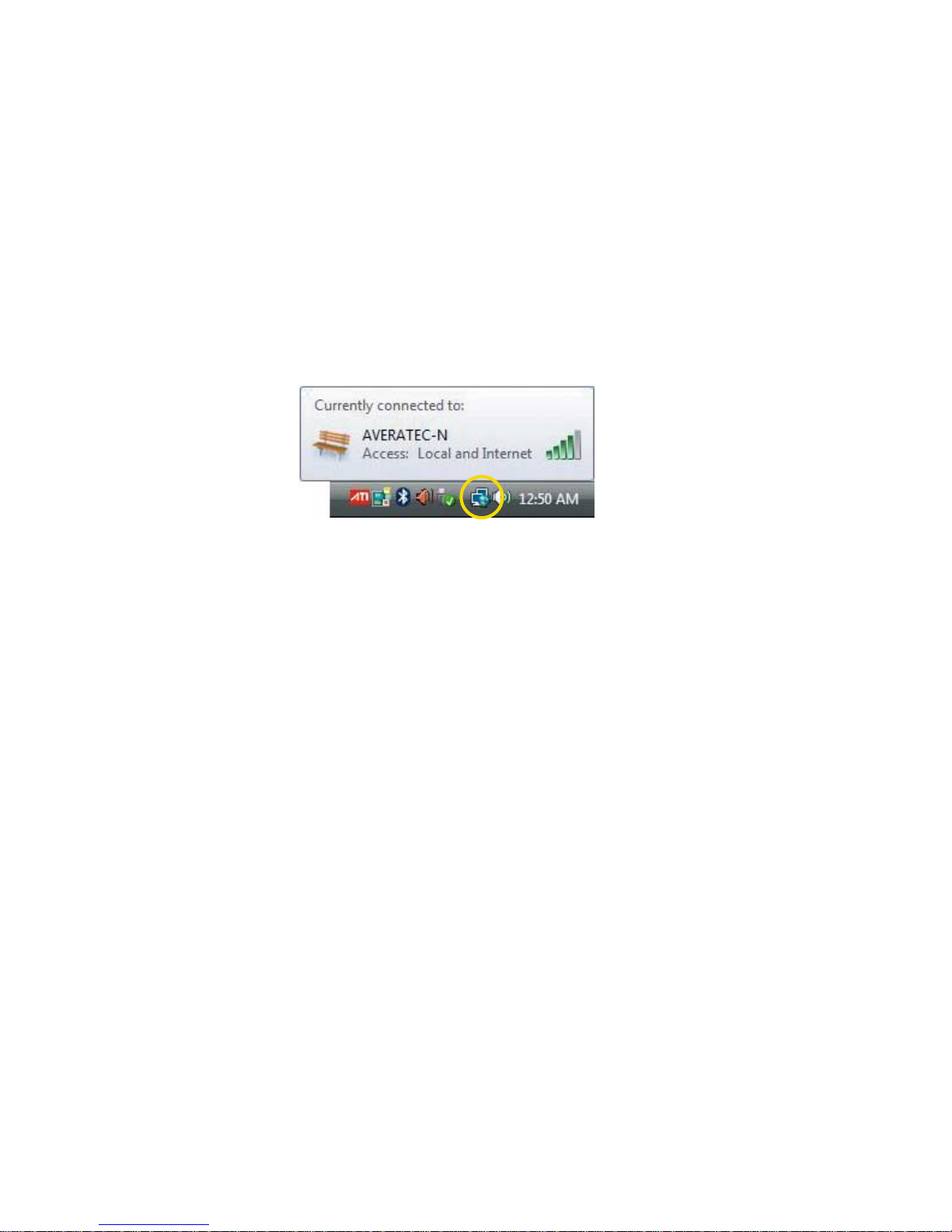
5. Once connection is successfully established, the network icon on the status bar will change its shape.
Page 31

3
Chapter 3 Using the Keyboardand Mouse
Using the Keyboard and Mouse
Chapter
3
Page 32

3-1
Chapter 3 Using the Keyboard and Mouse
Along with the mouse, your keyboard is one of the main tools for interacting with your PC. The keyboard allows you to
enter text into the PC, for example, in a letter, or email.
Use keyboard shortcuts
Keyboard shortcuts are a combination of key presses that perform common functions, for example, pressing the CTRL
and C keys allows you to copy something, and CTRLand V allows you to paste it somewhere else. The Help and
Support Center contains a list of common keyboard shortcuts.
Click Start > Help and Support.
The Keyboard
Page 33

3-2
Chapter 3 Using the Keyboard and Mouse
Using special keys on the keyboard
Keys on the keyboard, that are described in the following table serve special functions when your computer is running
your operating system or application programs.
Moves the cursor one tab to the right in normal mode and one tab to the left in Shift mode.
Changes the letter keys from lowercase to uppercase; changes back to lowercase when pressed again. The
numeric/symbol keys on the top row of the keyboard and the symbol keys in the main part of the keyboard are not
affected.
Tab
Caps Lock
Key Purpose
Produces uppercase characters or the top symbols on the keys when used with the maincharacter keys.
Produces lowercase characters when the Caps Lock function is on.
Shift
Works with other keys to perform special (control) function.Ctrl
Works with other keys to enter alternate character codes or functions.Alt
Moves the cursor back one space, deleting the character to the left of the cursor.Backspace
Ends a line of keyboard input or executes a command.Enter
Insert
Turns the insert function on and off.
Delete
Deletes the character marked by the cursor.
Home, End,
PgUp, PgDn,
Control cursor location.
Esc
Controls the current command line or operation.
Num Lock
Changes the function of the numeric/cursor keys from entering numbers to positioning the cursor.
Page 34

3-3
Chapter 3 Using the Keyboard and Mouse
Changes use of the numeric keys on the numeric keypad as mouse keys. To enable the function of the key, set the
Mouse tab in “Accessibility Options” in Control panel.
Key Purpose
Perform special functions within application programs.F1-F12
Outputs the screen display captured on the clipboard. When used with alt key, this key captures active
window.
Print Screen
Captures the screen display on the clipboard. When used with Alt key, this key captures active window.Sys Rq
Controls scrolling in some applications.Scroll Lock
Suspends the current operation.Pause
Break
Stops the current operation (used with Ctrl).
Displays the start menu.
Displays the short menu for the selected location. It corresponds to the right button of a mouse and displays a
different menu applicable to Windows other application programs.
The Caps Lock, Num Lock, and Scroll Lock keys work as toggles; press the key once to turn on a function and again to
turn it off. When the function is enabled, the corresponding light in the upper right corner of the keyboard is on.
The numeric keys on the numeric keypad of your keyboard can be used as MouseKeys to move a mouse pointer. To use
the numeric keys as MouseKeys, first you should set the Mouse tab in “Accessibility Options” of the Control Panel.
Note
✓ Depending on the model, your keyboard may differ from the illustrations described in this user’s guide.
Page 35

3-4
Chapter 3 Using the Keyboard and Mouse
The mouse is one of the main tools for working with your computer. It allows you to move the arrow around the screen.
You can also use it to open programs and interact with menus and text. A normal mouse has three buttons :
Drag and drop ?
You can drag and drop text, icons, or shortcuts with your mouse. Click an item with the left button and keep the button
held down. Move the cursor to the new location and let go.
The Mouse
Using a mouse
Generally a mouse
functions as follows:
This is your man button. Use a single-click to select an item, or insert the cursor at a
certain point in text. Use a double-click(pressing the button twice, quickly) to open a
program or document.
Left button
You can clicck an icon, or area on the screen, to open a “Context Menu”. These menus
give you quixk access to common functions, for example, copy and paste.
Right mouse
button
The scroll wheel changes functions depending on what program you are in. On the
Internet or in a document you can scroll up and down a page. In a graphics program it
might let you zoom in and out on a picture.
Scroll wheel
Press and release the left mouse button once.Click
Quickly press and release the left mouse button twice.Double click
Press and release the right mouse button once.Click with the right mouse button
While pressing and holding down the left mouse button, move it to
another location and then release the mouse button.
Drag
Page 36

4
Chapter 4 Using the Multimedia Features
Using the Multimedia Features
Chapter
4
Page 37
4-1
Chapter 4 Using the Multimedia Features
The Averatec All-in-One PC is fitted with a slim-tray-loading optical drive (COMBO or DVD Recorder).
Using the Optical Drive
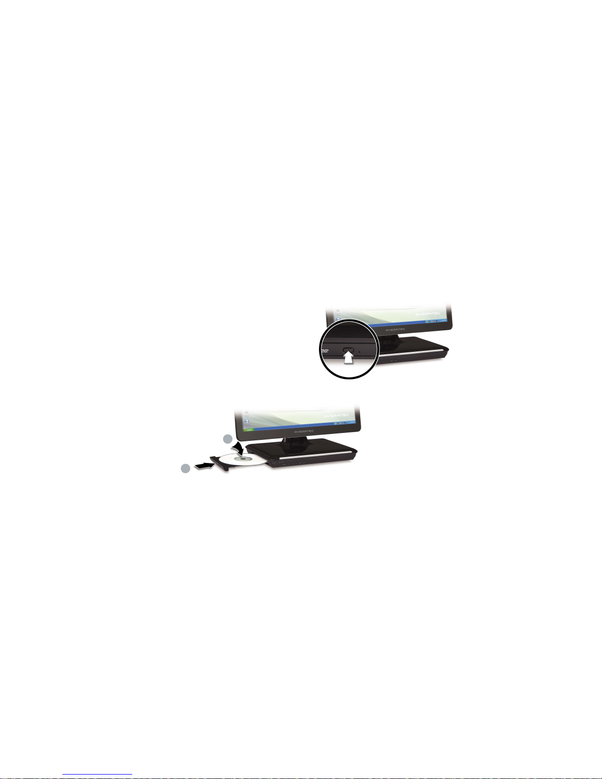
Tray-loading CD drive
1. Press the Eject button of the CD/DVD drive.
2. Press the CD/DVD Drive.
3. Eject CD/DVD
Press the Eject button of the CD/DVD drive on the left side of the Averatec All-in-One PC.
You can then remove the CD/DVD.
1
2
Page 38

4-2
Chapter 4 Using the Multimedia Features
Note
✓If you can not eject a CD/DVD from the drive, click Start, choose Computer,
right-click on the CD/DVD drive that the CD/DVD is in and choose
Eject in the
popup menu.
✓If you can not eject a CD/DVD from the drive by pressing the eject button and choosing the Eject menu, insert the paper clip
into the emergency eject hole as far as it will go then the tray will be slightly open. Pull out the tray and remove a CD/DVD from
the tray.
✓Make sure CD/DVD is not inserted upside down.(CD label side facing toward upside of PC).
✓Labels on CD/DVD may cause noise when CD/DVD drive is working. Remove labels on CD/DVD for safe use.
1
2
3
Page 39
4-3
Chapter 4 Using the Multimedia Features
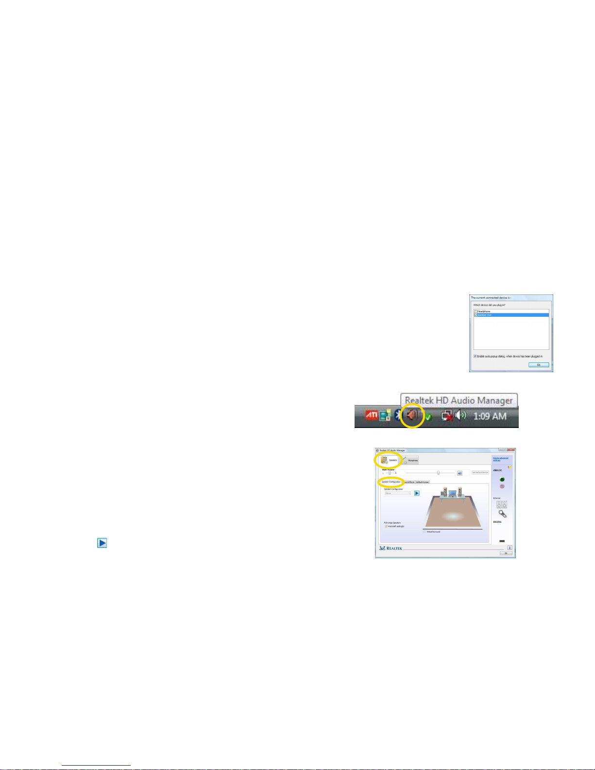
Setting up your external speakers
To use external speakers you should verify that the sound setting is adjusted correctly. To set the multi-channel speakers,
follow these steps.
Setting Up and Adjusting the Audio Features
Note
✓
Connecting the speakers will cause a window to appear confirming detection of the device.
1. Double click the Realtek HD Audio Manager icon.
2. Click the Speakers tab, click the Speaker Configuration tab.
3. ClickPlay( ) button.
Page 40
4-4
Chapter 4 Using the Multimedia Features
Adjusting the Speaker Volume
The Speaker volume level can be adjusted easily with
the button located on the Front side of the PC.
Integrated
speakers
Integrated speakers
Volume button (Up/Down)
To adjust the volume level, press the left volume button to increase
the volume level and the Right volume button to decrease the
volume level.
Mute button
To mute the speaker sound, press it once to enable mute and press it
again to disable mute.
Audio mute
Adjusting volume
The Averatec All-In-One PC has built-in speakers on the base of the system.You can adjust the volume by clicking the volume
adjustment buttons located on the front side of the PC and / or by using the volume control feature in Windows Vista.
Volume increase / decrease
Page 41

4-5
Chapter 4 Using the Multimedia Features
Using the internal microphone
Your PC comes with a built-in internal microphone near the power button on the left of the computer. Use the built-in
internal microphone to record sound for your webcam videos, and to use instant messenger or chat software to have
video chats online.
You can use the internal microphone from a distance of up to 1.5 feet (one meter) from the Computer.
Microphone
1. Double click the Realtek HD Audio Manager icon.
Page 42
4-6
Chapter 4 Using the Multimedia Features
2. Click the Microphone tap.
3. Click the Microphone Boost.
4. After adjusting Microphone Boost, click the button.
5. Click the OK.
Page 43

4-7
Chapter 4 Using the Multimedia Features
You can take photos and chat with your friends.
Take photos
To take photos, follow the next steps :
1. Double click the CyberLink YouCam icon( ) on the desktop.
3. Click the Snapshot button( ) on the CyberLink YouCamscreen.
2. The CyberLink YouCam will be run and a yellow light on the webcam LED indicates your PC is ready to take photos.
Using Your Webcam
Note
✓For more information, refer to the Help of the program. You can see the Help by clicking the help button( ) on the upper right
side of the screen.
Page 44
4-8
Chapter 4 Using the Multimedia Features
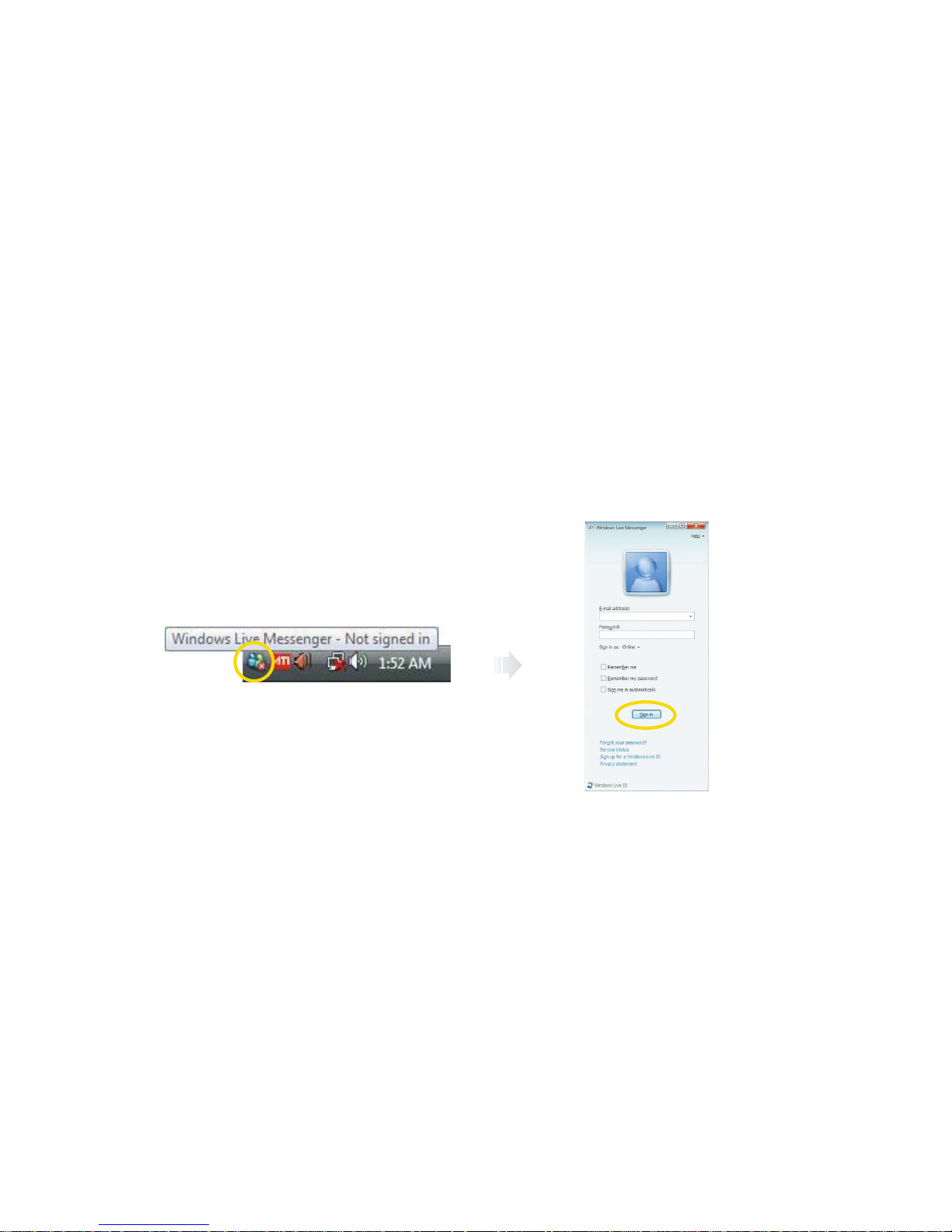
Video chatting
To chat with video, both your system and the system of the person you want to chat with must have a web camera or a
CCD camera installed. You also need to download and install a messenger program. The screen that you will see varies
depending on the type of the messenger program you’re using.
1. Run the messenger program to register your user email address. When the messenger is ready. double-click on the
Windows Messenger icon. Select Sign in.
Page 45
4-9
Chapter 4 Using the Multimedia Features
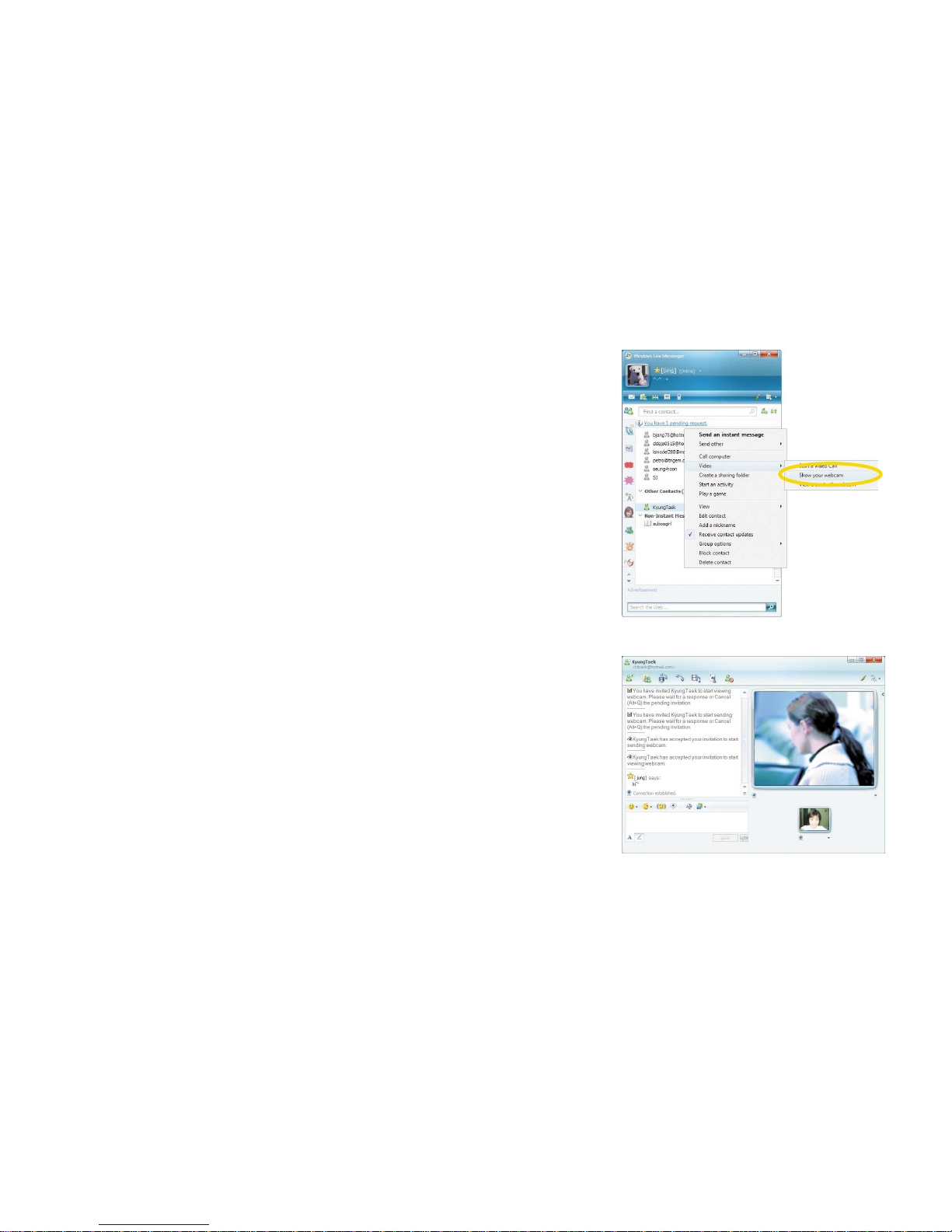
2. Right-click on your chat partner and then select Show your webcam,
as illustrated below.
3. Now you’re ready to start chatting!
Page 46

4-10
Chapter 4 Using the Multimedia Features
Removing multi-media card
Grip the tip of the card and take it out from the slot.
(Do not remove the card while you are using it, as you could corrupt
the contents.)
Memory card readers
Memory card readers are a relatively new addition to personal computers
and are a great alternative to floppy disks. Memory cards come in several
different formats and are used in a variety of electronic devices including
digital cameras, PDAs, mobile phones and more.
Averatec's All-In-One PC accepts many types of multi-media cards into the multi-card reader slot on the right side of the PC.
Multi-Media card
SD (Secure Digital™), MS-PRO™, MS-PRO™ Duo, MS(Memory Stick™),
MMC(MultiMediaCard™), RS-MMC
Inserting the multi-media card
To insert correctly, refer to the pictures. The cards are not inserted
completely, the tip of the cards will remain out of the slot. (Insert
cards with label side facing toward the back of the PC.)
Using the Multi-Card Reader
Insert cards with label
side facing toward the
back of the PC.
MSMS-PRO
(use the
adapter)
MS-PRO Duo SDMMC
RS-MMC
(use the
adapter)
Page 47
4-11
Chapter 4 Using the Multimedia Features
Note
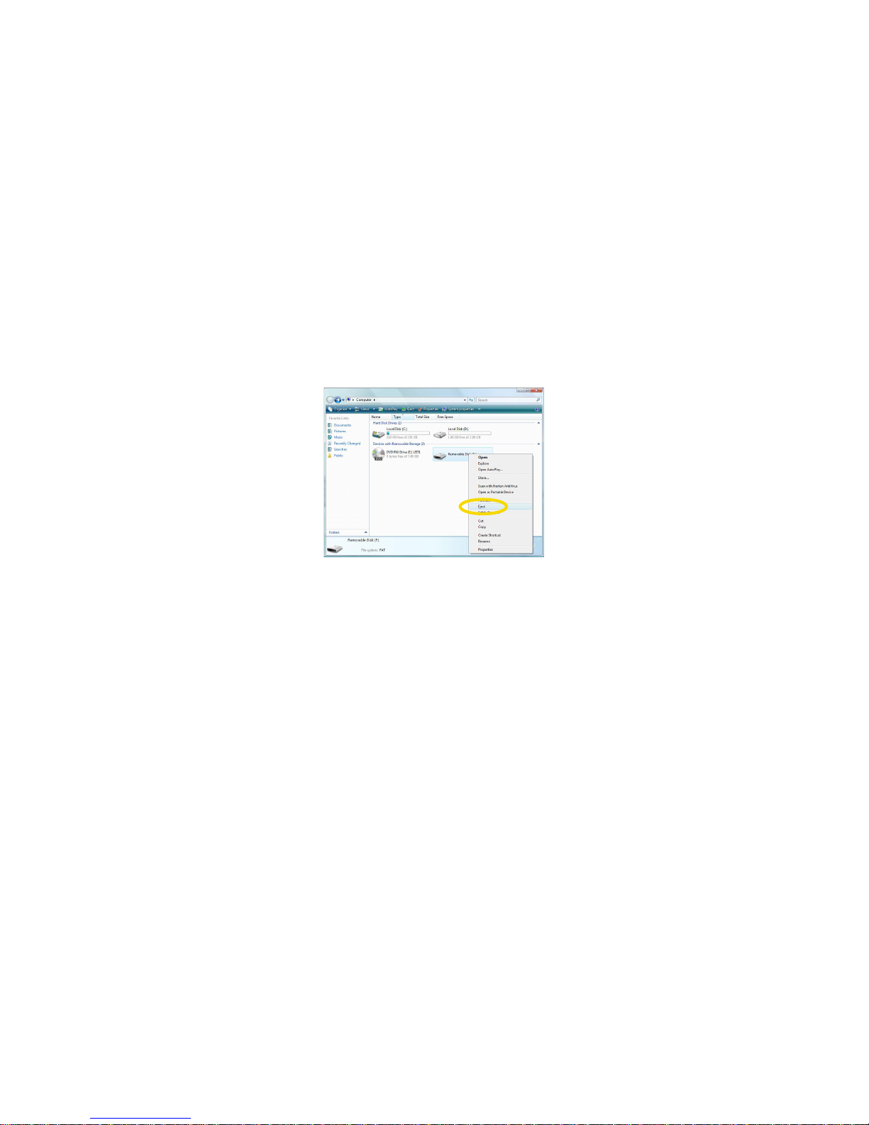
✓ Click the <Start> menu and select Computer. On the Computer screen, right-click on the Combo Socket icon and select Eject.
✓ This does not physically eject the media card. However, it does ensure all data is written to the media card prior to the physical
removal of the card.
Page 48

4-12
Chapter 4 Using the Multimedia Features
Windows Media Center can handle a variety of multimedia content. You can watch live or recorded TV, listen to digital music,
view pictures and personal videos, play games, burn CDs and DVDs, listen to FM and Internet radio stations, or access content
from online services. You can also use Windows Media Center to make your own music CDs.
To better understand how Windows Media Center works, you can learn more from the following:
- Watch TV
- Record TV
- Play video and watch pictures
- Listen to music
- Play your digital media anywhere in the home
- Listen to radio
- Play a CD or DVD
- Burn a CD or DVD
- Browse, stream, and download digital media from Online Media
- Play games
Setting Up Media Center
Note
✓
An optional FM tuner is required to play FM radio stations in Windows Media Center.
✓
If your computer has no TV tuner, an optional analog or digital TV tuner is required to play and record TV in Windows Media
Center.
Page 49

5
Chapter 5 Adjusting the LCD Screen
Adjusting the LCD Screen
Chapter
5
Page 50

5-1
Chapter 5 Adjusting the LCD Screen
LCD Care
LCD screens are delicate devices that need careful handling. Please pay attention to the following precautions :
- When you are not using the computer, keep the LCD screen closed to protect it from dust.
- If you need to clean your LCD screen, use a soft tissue to gently wipe the LCD surface.
- Do not put your fingers or sharp objects directly on the surface and never spray cleaner directly onto the display.
- Do not press on, or store any objects on the cover when it is closed. Doing so may cause the LCD to break.
Adjust the tilt of the LCD for your convenience.
Placing the LCD in Standby
Page 51

5-2
Chapter 5 Adjusting the LCD Screen
Brightness control button (toggle)
Adjusting the Brightness of the Monitor
You can adjust the brightness by clicking the brightness control button on
the front side of the PC. There are 5 levels of LCD brightness adjustment
available. Each press of the brightness control button will cycle through
each level.
100%
(full brightness level)
60% of brightness level
90% of brightness level 80% of brightness level
70% of brightness level
Using the brightness control button
Page 52

5-3
Chapter 5 Adjusting the LCD Screen
Adjust screen resolution
1. Click the Start button > Control Panel > Appeaarance and Personalization > Adjust screen resolution.
2. Change the Resolution.
Adjust Screen Resolution
Page 53

5-4
Chapter 5 Adjusting the LCD Screen
Advance settings
1. Click the Advanced Settings.. button.
2. Click the ATI Catalyst(TM) Control Center tab, click ATI Catalyst
Control Center button.
Page 54

5-5
Chapter 5 Adjusting the LCD Screen
- Display Manager(Displays Properties)
This feature allows you to connect external display devices. You to adjust
the color quality, screen resolution, and refresh rate for your display.
- Color
This feature allows you to adjust the color rate of
your display.
- 3D
The appropriate 3D as pects are automatically
loaded basesd on your graphic.
Page 55

6
Chapter 6 Using the Optional VESA Mount
Using the Optional VESA Mount
Chapter
6
Page 56
6-1
Chapter 6 Using the Optional VESA Mount
Using the Optional VESA Mount
1. Turn off your system and remove all cables.
Your system has four VESA Mount holes on the bottom surface for using a VESA Mount (not included). To use it, follow the
next steps:
2. Place LCD in down position and insert the hinge lock clip as shown below.
Hinge lock clip
Note
✓Please contact to Trigem USA for purchasing Hinge lock clip shown below.
Page 57

6-2
Chapter 6 Using the Optional VESA Mount
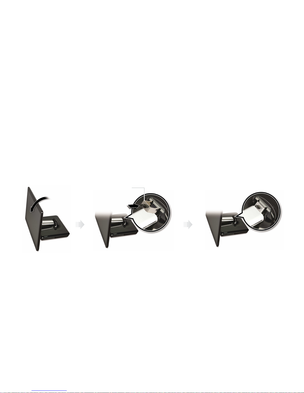
3. Fold the LCD panel.
4. Place down the LCD panel on a soft and flat surface to locate the mounting holes on the bottom of your system.
(Be careful not to damage the LCD panel.)
5. To hold the the system module more firmly, insert a flat item (such as a book) between the LCD and system module.
6. Attach the VESA Mount bracket to your system.
7. Follow the instructions in the User’s Guide that came with your VESA Mount.
Page 58

6-3
Chapter 6 Using the Optional VESA Mount
Note
✓The mounting hole pattern of your system is 100 mm x 100 mm.
To purchase a VESA Mount, please refer to this size.
✓Removing the hinge lock clip
To remove the hinge lock clip, follow the next steps:
Unfold the LCD panel.
1
Push down the hinge arm slightly and remove the hinge lock clip.
2
You can adjust angel of the LCD panel.
3
1 2
Hole
Hinge arm
Page 59

7
Chapter 7 System SETUP(BIOS)
System SETUP(BIOS)
Chapter
7
Page 60

7-1
Chapter 7 System SETUP(BIOS)
For System Setup, setup only the items that you need. Note that incorrect settings of Setup items could result in system
malfunction.
Entering Setup
After powering on the system, press <Del> to enter the System Setup screen.
BIOS Action Keys
Leaves a sub-menu to return to the previous menu OR exits the BIOS setup while saving
changes.
Shows the Sub Menu
ESC Exit
Enter Select
Function Key Command Description
Shows the Help ScreenF1 General Help
Saves default settingF9 Default Setting
Saves changes and reboots the computer.F10 Save and Exit
Selects the next field.<Tab> Select a field
Selects the next item.Select an item
-, + value
Selects the next value within a field.
Page 61

7-2
Chapter 7 System SETUP(BIOS)
System Setup Options
Main Menu
Advanced Menu
Page 62
7-3
Chapter 7 System SETUP(BIOS)
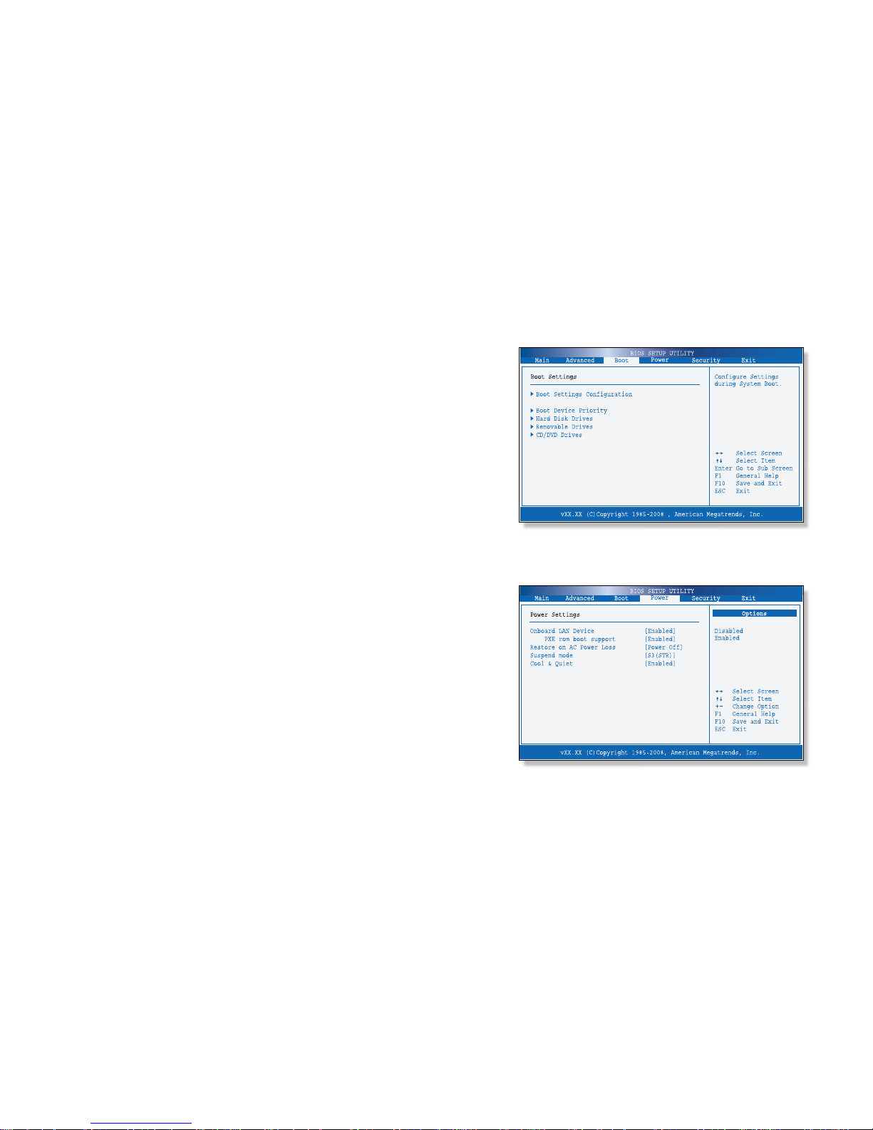
Boot Menu
Power Menu
Page 63
7-4
Chapter 7 System SETUP(BIOS)
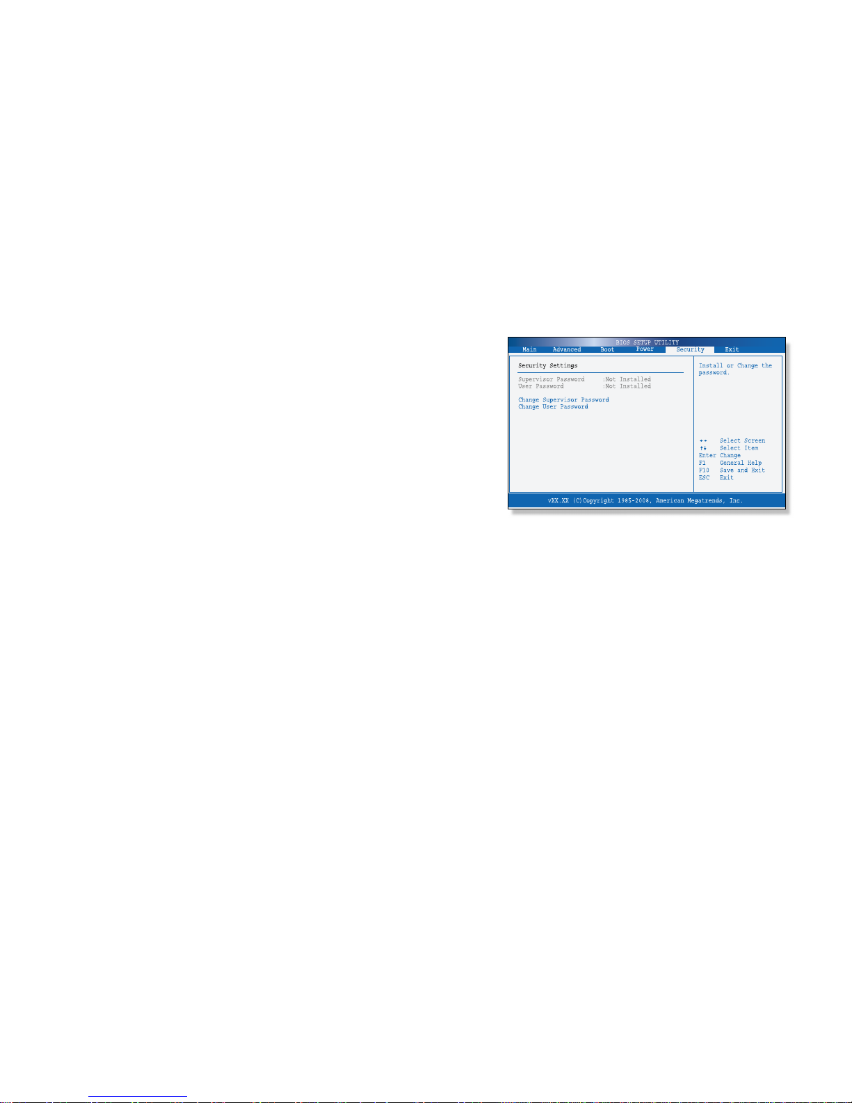
Supervisor Password
Shows the setup status of the Supervisor Password: Installed, if a upervisor Password is set, or Not Installed.
User Password
Shows the setup status of the User Password: Installed, if a User Password is set, or Not Installed.
Change Supervisor Password
Setting up a password helps you prevent unauthorized users from accessing the system. In the factory settings, password
is Not installed. A password can have up to six alphanumeric characters and/or numbers.
Security Menu
Sets up a password to prevent any unauthorized user from accessing
the system.
Page 64

7-5
Chapter 7 System SETUP(BIOS)
Set up Supervisor Password
1. On the initial System Setup screen, Go to Change Supervisor Password, and then press Enter.
2. On the following screen, enter the password and then press Enter.
Then enter the same password again and press Enter.
Enter New Password Confirm New Password
3. If you entered the correct password, the following window will appear. Press Enter.
This completes setting up a password.
Password installed
[OK]
The Supervisor Password is at a higher level than the User Password.
Page 65

7-6
Chapter 7 System SETUP(BIOS)
Save Changes and Exit
Save the changes you have made and exit the utility.
Discard Changes and Exit
Exit the utility without saving the changes you have made.
Discard Changes
Aban your changes and reload the previous configuration before running the utility.
Load Optima Defaults
Select this item to load the default settings for optimal system performance.
Exit Menu
Page 66

A
Appendix A Specifications
Specifications
Appendix
A
Page 67

A-1
Appendix A Specifications
Specifications and Descriptions
The main board has a built-in (AMD RS780MN, SB700) chipset, and supports various functions such as an LGA 775 type
processor, system memory, a controller and a 3D graphic function.
AMD Athlon(tm) X2 Dual Core Processor
- AMD RS780MN
- SB700
- 667/800 MHz DDR2 SDRAM
- Two 200-pin Non-ECC DDR2 SDRAM DIMM sockets support up to 4GB
- Integrated GFX on RS780MN(Onboard) or optional external graphics card (M82SCE)
- Integrated High Definition Audio Interface
- Realtek ALC662 Audio Codec
- Built-in stereo speakers (2W x 2)
- Built-in microphone
Realtek RTL8168D Gigabit Ethernet
- Integrated 10/100/1000 transceiver
- Supports Full Duplex flow control
- Wake-on-LAN and remote wake-up support
Mini Express Card
- IEEE 802.11 b/g compliant
- WiFi Personal Area Network capabilities
Processor
Main Chipset
Memory
Video
Audio
Communications
Feature Specifications
Note
✓
The processor depends on the model of computer you purchased.
Page 68

A-2
Appendix A Specifications
18.4-inch (viewable) glossy widescreen TFT active-matrix LCD, 1680 by 945 pixels
ATSC/NTSC, Mini PCI Express Type
S-Multi(Tray Type)
- Built-in IR receiver
- Built-in Web camera (1.3 mega pixels)
- Multi-media card reader(4-in-1)
Right side
- Two USB connectors
- A MIC jack
- A Headphone jack
- Memory Card reader(4-in-1) slot
Back side
- Two USB connectors
- A e-SATA & USB Connector
- A LAN connector
- A DVI connector for external display
Display
HD TV Card (Optional)
Optical Drive
Others
Interfaces
Feature Specifications
Page 69

A-3
Appendix A Specifications
- Integrated GFX model : 65W, 100~240V, 19V/3.42A or 20V/3.25A
- Optional external graphic model : 90W, 100~240V, 19V/4.74A
- 447mm(W) X 369.5mm(H) X 214mm(D)
- 4kg
Temperature
- Operation : +5
o
C to 35 oC
- Storage : -10
o
C to 55 oC
Humidity
- Operation : 30 % to 80 % (noncondensing)
- Storage : 20 % to 90 %
Power Supply
System Size and Weight
Environmental Requirement
Feature Specifications
Page 70

B
Appendix B Troubleshooting & Support
Troubleshooting & Support
Appendix
B
Page 71

B-1
Appendix B Troubleshooting & Support
Troubleshooting
This chapter instructs you how to deal with the problems you might experience when using your
computer. The problem is listed first, followed by the solution. Read it before calling a technician
if a problem occurs.
Display
The brightness and contrast controls aren’t set properly
Adjust the brightness and contrast controls on the right side of the LCD panel.
You have a screen blanking utility installed or your computer entered power
management mode.
Press any key or move your mouse. Your current screen will reappear.
How do I change the display resolution or color correction?
To change the display resolution or color correction, use the Graphics Properties
window.
To change the display resolution and color depth, follow these steps:
1. Click Start > Control Panel > Adjust screen resolution.
2. When the Display Properties window appears, click the Advanced Settings button.
3.
Click Intel® Graphics Media Accelerator Driver tab, and click Graphics Properties… button.
4. Select the Display Settings tab, adjust color quality, screen resolution, and refresh rate.
5. Select the color correction tab, adjust color, gamma, brightness, and contrast.
The monitor doesn’t work
Cause Solution
Page 72

B-2
Appendix B Troubleshooting & Support
Audio
To control the audio volume level, use the volume control box.
Click on the Speaker icon located on the right of your Windows taskbar. When the
volume control box appears, drag the volume bar up or down to adjust the audio
volume level.
Audio has been muted.
Click on the Speaker icon located on the right of your Windows taskbar. When the
volume control box appears, verify that the Mute option check box is empty.
Volume is turned down
The volume level may be too low. Click on the Speaker icon located on the right of your
Windows taskbar. When the volume control box appears, drag the volume bar upward.
The speakers are not properly connected.
Make sure that the speakers are properly connected to the computer.
How do I control the audio
volume level?
Computer doesn’t produce
any sound
Cause Solution
Page 73

B-3
Appendix B Troubleshooting & Support
Hard Disk Drive
The files stored on your hard disk may be fragmented.
Check for lost allocation units by running Disk Defragmenter. (For more information,
refer to the Windows Help. To open Windows Help, click the Start button, and then
clickHelp and Support.)
The files stored on your hard disk may be corrupted.
Check for lost allocation units by running Disk Defragmenter. (For more information,
refer to the Windows Help. To open Windows Help, click the Start button and then click
Help and Support.)
Hard disk drive operation
seems slow
Hard disk drive access
indicator light stays on
Cause Solution
LAN / Wireless LAN
- Check that the LAN cable is connect to the LAN port.
- Check that your Internet provider is not currently experiencing differenties.
- Make sure that AP (Access Point) is on and you are within range of a wireless Internet AP.
- If AP is on and you are within range of an AP, connect your system to the network that
you want to join for getting Internet access. For more information, refer to ‘Connect to
the Internet’ in Chapter 2.
I can’t connect to the
Internet
Wireless LAN doesn’t work
Cause Solution
Page 74

B-4
Appendix B Troubleshooting & Support
Power
Computer is not properly connected to a grounded wall outlet.
Make sure the power cord is firmly plugged into the wall outlet and into the computer.
Wall outlet is not working.
To check to see whether the wall outlet works, plug other device (such as a lamp) into
the wall outlet. If it is not working, use other wall outlet.
When the computer turned down by sudden power failure, it will not operate if
you press the power button. To turn on the computer, refer to the followings:
Unplug the power cord to turn off your computer and wait about 10 seconds for
complete discharge and re-plug the power cord. Then press the power button.
My computer doesn’t
work
Cause Solution
Page 75

B-5
Appendix B Troubleshooting & Support
Optical Drive
CD/DVD is not properly seated in the optical drive.
Eject the CD/DVD, gently but firmly press down on the CD/DVD to seat it in the drive,
then reload.
Your optical drive is not recognized.
Turn off the computer, wait at least 30 seconds, and then turn on the computer.
CD/DVD has been inserted upside down.
Eject the CD/DVD, turn it over, then reload.
(The label on the CD/DVD/CD-R(W) should be facing up.)
CD/DVD is dirty.
Clean the CD/DVD with a CD/DVD cleaning kit (available in computer stores).
CD/DVD is defected.
Try another CD/DVD. If it operates well, the CD/DVD is defected.
The optical drive cannot
read CD
Cause Solution
Page 76

B-6
Appendix B Troubleshooting & Support
Keyboard
Check the keyboard is connect to the computer.
Keyboard doesn’t work
Cause Solution
Mouse
Check the mouse is connect to the computer.
Mouse doesn’t work
Cause Solution
Page 77

B-7
Appendix B Troubleshooting & Support
Recovering Your Original Software
WARNING
- If you recover your hard disk, you will lose all the data and programs on your hard disk. After recovering, you must
reinstall any software not originally installed from the factory. Be sure to backup your own data before running the
recovery process.
- Please run the recovery process after connecting the power adapter to your system. During the recovery process, if
the battery is drained, the system will be turned off and it may cause damage to your hard disk.
To recover the hard disk drive as the factory setting, refer to the follow steps:
1
Connect the power adapter to your system.
2
Press the power button.
3
When the “[F5] key for HDD Recovery” message appears on the screen, press [F5] on the upper side of the keyboard.
4
When the “Windows Setup [EMS Enabled]” message appears, press Enter.
5
Restoration procedures will be started, follow the on-screen instructions to recover your hard disk drive.
6
Select the menu that you want. (We will show the steps after selecting the “Recovery of the Entire Hard Disk” menu for
example.)
7
If you select the "Recovery of the Entire Hard Disk” menu, you can see the caution window.
Click OK after checking. (To cancel the recovery, click Cancel.)
Page 78

B-8
Appendix B Troubleshooting & Support
Getting Help
Contacting Technical Support
Returning Units for Warranty Repair
8
Windows Vista starts and the registration program runs.
9
To set up and register with Microsoft for using your computer, follow the displayed messages.
(For more information, refer to “Getting Started with Windows Vista.”)
Note
✓Do not delete the Recovery partition on the Computer Management window for recovery.
(This partition takes about 2GB hard disk space.)
Page 79

C
Appendix C Glossary
Glossary
Appendix
C
Page 80

C-1
Appendix C Glossary
Term & Definitions
ACPI (Advanced Configuration and Power Management Interface)
Modern standard for reducing power usage in systems
API(Advanced Power Management)
Modern standard for reducing power usage in systems
Application
A piece of software used to carry out a particular task, like a Microsoft Word program or graphics package.
Backup
A copy of a file, folder or disk made for safe keeping.
Baud rate
The baud rate is the number of bits transmitted per second in serial communications.
BIOS (Basic Input / Output System)
BIOS is a set of routines that affect how the system transfers data between system components, such as memory, disks,
and display adapter. The BIOS instructions are built into the system’s read-only memory. BIOS parameters can be configure
by the user through the BIOS Setup program.
Page 81

C-2
Appendix C Glossary
Bit (Binary Digit)
Represents the smallest unit of data used by the system. A bit can have one of two values: 0 or 1.
Boot
Boot means to start the system operating system by loading it into system memory. When the manual instructs you ºº
‘boot’ your system, it means to turn ON your system.
Byte (Binary Term)
One byte is a group of eight contiguous bits. A byte is used to represent a single alphanumeric character, punctuation
mark, or other symbol.
Contrast ratio
This is the difference of brightness between the brightest and the
darkest area. Higher contrast ratio supports more original-like colors.
Cursor
A blinking line or block on the screen that indicates where your next keystroke will have an effect.
CPU (Central Processing Unit)
The CPU, sometimes called Processor, actually functions as the brain of the system. It interprets and executes program
commands and processes data stored in memory.
Page 82

C-3
Appendix C Glossary
Default
A pre-set value used by a system until it is specifically changed by a user.
Device
A device is a piece of hardware attached to a system (usually a peripheral), for example a printer or mouse.
Device Driver
A device driver is a special set of instructions that allows the system’s operating system to communicate with devices such
as VGA, audio, Ethernet, printer, or LAN.
Disk
Magnetic medium used for storing information.
Drive
The device that holds and reads a hard disk or diskette.
DVD
DVD is essentially a bigger, faster CD that can hold video as well as audio and system data.
With these capacities and access rates, DVD discs can provide you with dramatically-enhanced high-color, full-motion
videos, better graphics, sharper pictures, and digital audio for a theater-like experience.
File
A collection of related instructions or data stored on disk.
Page 83

C-4
Appendix C Glossary
Hard Disk
A disk for storing information that is not removable from the system. They usually have large storage capacity and provide
fast access to data.
Hardware
Hardware is a general term referring to the physical components of a system, including peripherals such as printers, and
pointing devices.
Horizontal frequency
Number of horizontal lines displayable per second is called Horizontal frequency. The unit is kHz.
Input
Information going into the system, usually from you typing at the keyboard or from a program reading from disk.
I/O
Abbreviation for input / output.
Page 84

C-5
Appendix C Glossary
Kilobyte (Kbyte or KB)
1024 Kbyes, denoted as 1Kbyte, 1KB or 1K.1024 Kbytes equal 1 Megabyte (or Mbyte), over one million bytes.
LCD
LCD is an initial of Liquid Crystal Display. In certain temperature range, the material has intermediary characteristics
between solid and liquid. Using the characteristics, the material can be used to display information.
Megabyte (Mbyte or MB)
A unit of storage in a system denoting 1024 Kbytes. It is usually denoted as 1 Mbytes or 1 MB.
Memory
Memory is where the system stores data and programs.
Output
Data that the system sends to the console, disk or some other devoce.
Password
A series of characters needed to gain access to a system, file or directory.
PC
An abbreviation for personal computer.
Page 85

C-6
Appendix C Glossary
Peripheral
An external device connected to the system. Peripherals are generally used for input and output. Examples include disks,
LAN, and printers.
Plug and play function
- This is a function for easy, convenient and automatic configurations of new hardware.
- When the LCD monitor is connected to a computer, using DDC(Display Data Channel) - a kind of communication
medium, optimal screen status is configured.
PCI Bus (Peripheral Component Interconnect Local Bus)
PCI bus is a specification that defines a 32-bit data bus interface. PCI is a standard widely used by expansion card
manufactures.
POST (Power On Self Test)
When you turn on the system, it will first run through the POST, a series of software-controlled diagnostic tests. The POST
checks system memory, the motherboard circuitry, the keyboard, the diskette drive, and other I/O devices.
Power saving
To save energy while the system is non operating, a signal must be received from video chipsets to initialize Energy saving
status. This signal is called VESA DPMS (Video electronics standards association power management signaling). Modern
LCD monitors mostly support this saving function (DPMS). Since mostly LCD monitors are not used solely, this energy
saving function is not controlled by the LCD monitor, but rather controlled by the system.
Page 86

C-7
Appendix C Glossary
Program
A series of specially coded instructions that perform a specific task when executed by a system.
RAM (Random Access Memory)
RAM is the place in a system where the operating system, application programs, and data in current use are temporarily
kept so that they can be quickly reached by the system’s processor instead of having to read from and write to slower
storage such as the hard disk or optical disc.
Suspend Mode
In Save-to-RAM (STR) and Save-to-Disk (STD), the CPU clock is stopped and the system devices are put in their lowest
active state. The PC enters Suspend when the system remains idle for a specified amount of time.
System Disk
A system disk contains the core file of an operating system and is used to boot up the operating system.
ROM
Read-Only Memory. This is a type of memory which you can only read or copy; you cannot alter it’s content. It is normally
used to contain the systems diagnostic programs, and a very basic input / output system.
USB (Universal Serial Bus)
A 4-pin serial peripheral bus that allows plug and play system peripherals such as keyboard, mouse, scanner, printer to be
automatically configured when they are attached physically without having to install drivers or reboot.
Page 87

C-8
Appendix C Glossary
Video Memory
A special area of memory used by the hardware which operates the system’s display or monitor.
View angle
LCD has lower power consumption, low voltage requirement, and is thin and light, so that it is suitable for high resolution
full color pictures. However, its weak point is its narrow view angle. View angle means the angle from which the screen can
be watched. Wider view angel means
brightness and resolution are consistent without regard to viewers’ location.
Vertical frequency
Number of screen output repetitions per second is called Vertical frequency or ‘Refresh rate’. The unit is Hz.
Page 88

 Loading...