

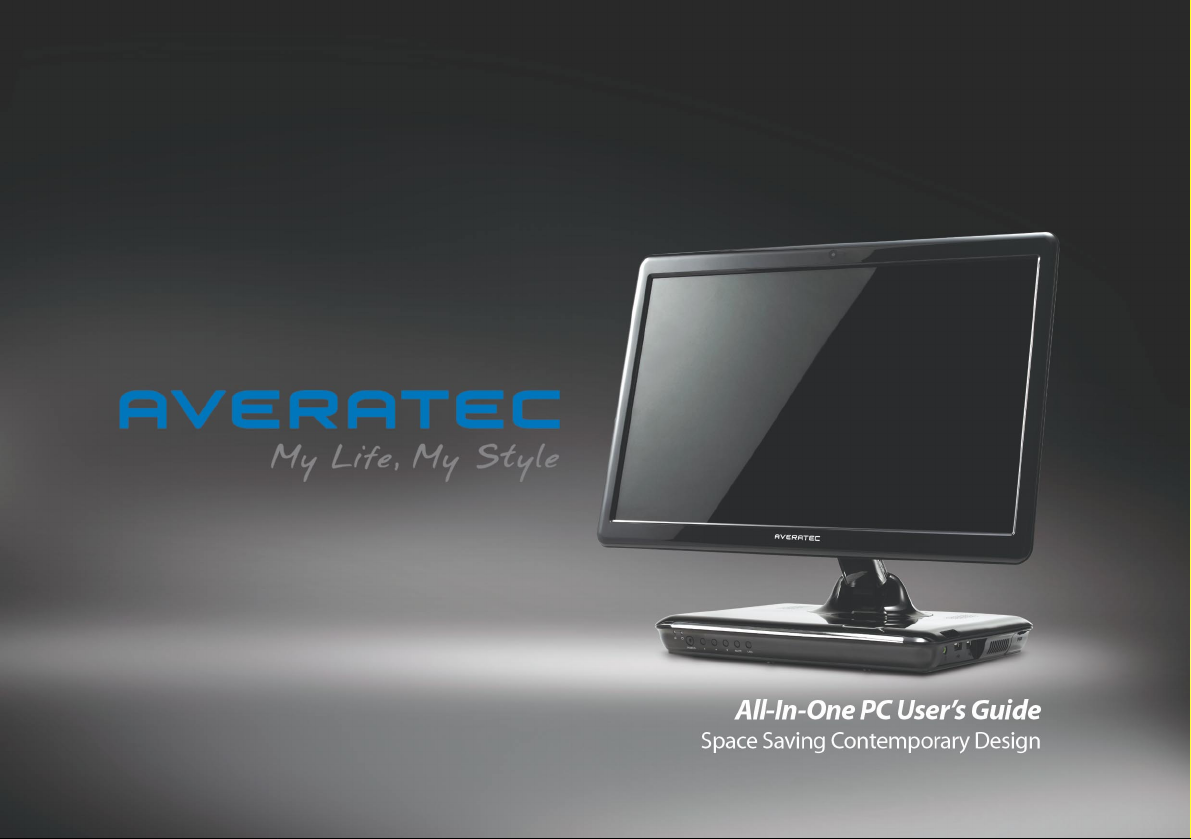
Page 1
Page 2

i
Before You Start
Regulations Information
FCC-B Radio Frequency Interference Statement
This equipment has been tested and found to comply with the limits for a Class B digital device, pursuant to part 15 of the
FCC rules. These limits are designed to provide reasonable protection against harmful interference in a residential
installation. This equipment generates, uses and can radiate radio frequency energy and, if not installed and used in
accordance with the instructions, may cause harmful interference to radio communications. However, there is no
guarantee that interference will not occur in a particular installation. If this equipment does cause harmful interference to
radio or television reception, which can be determined by turning the equipment off and on, the user is encouraged to try
to correct the interference by one or more of the following measures :
• Reorient or relocate the receiving antenna.
• Increase the separation between the equipment and receiver.
• Connect the equipment into an outlet on a circuit different from that to which the receiver is connected.
• Consult the dealer or an experienced radio TV technician for help.
Note
✓ The changes or modifications not expressly approved by the party responsible for compliance could void the user’s authority
to operate the equipment.
✓Shield interface cables and AC power cord, if any must be used in order to comply with the emission limits.
Page 3

ii
Before You Start
FCC Conditions
This device complies with part 15 of the FCC Rules. Operation is subject to the following two conditions :
1. This device may not cause harmful interference.
2. This device must accept any interference received, including interference that may cause undesired operation.
Page 4

iii
Before You Start
Optical Device Drive Notice
Battery Notice
Ethernet Notice
This equipment is indoor use and all the communication wirings are limited to inside of the building.
CAUTION
✓This appliance contains a laser system and is classified as a “CLASS 1 LASER PRODUCT.” To use this model properly, read the
instruction manual carefully and keep this manual for your future reference. In case of any trouble with this model, please
contact your nearest “AUTHORIZED service station.” To prevent direct exposure to the laser beam, do not try to open the
enclosure.
CAUTION
✓RISK OF EXPLOSION IF BATTERY IS REPLACED BY AN INCORRECT TYPE. DISPOSE OF USED BATTERIES ACCORDING TO THE
INSTRUCTIONS.
Power management status
System sleep mode
System Off mode
0.6 W
0.7 W
Without WOL
Without WOL
Page 5

iv
Before You Start
Macrovision Notice
This product incorporates copyright protection technology that is protected by U.S. patents and other intellectual property
rights. Use of this copyright protection technology must be authorized by Macrovision, and is intended for home and other
limited viewing uses only unless otherwise authorized by Macrovision. Reverse engineering or disassembly is prohibited.
Safety Instructions
1. Read the safety instructions carefully and thoroughly.
2. Save this User Guide for possible use later.
3. Keep this equipment away from humidity and high temperature.
4. Lay this equipment on a stable surface before setting it up.
5. The openings on the enclosure are used for air convection and to prevent the equipment from overheating. Do not
cover the openings.
6. Make sure that the power voltage is within its safety range and has been adjusted properly to the value of 100~240V
before connecting the equipment to the power inlet.
7. Place the power cord in a way that people are unlikely to step on it. Do not place anything on the power cord.
8. Always unplug the power cord before inserting any add-on card or module.
9. All cautions and warnings on the equipment should be noted.
Page 6

v
Before You Start
10. If any of the following situations arises, get the equipment checked by a service personnel:
• The power cord or plug is damaged.
• Liquid has penetrated into the equipment.
• The equipment has been exposed to moisture.
• The equipment has not worked well or you can not get it work according to Users Manual.
• The equipment was dropped and damaged.
• The equipment has obvious signs of breakage.
11. Never pour any liquid into the opening that could damage the equipment or cause an electrical shock.
12. Do not leave the equipment in an unconditioned environment with a storage temperature of 60°C (140°F) or above,
which may damage the equipment.
13. To prevent explosion caused by improper battery replacement, use the same or equivalent type of battery
recommended by the manufacturer only.
Page 7
vi
Before You Start
Information about ENERGY STAR
- The ENERGY STAR Computers Program was created by the EPA to promote energy efficiency and reduce air pollution
through more energy-efficient equipment in homes, offices, and factories.
- One way products achieve this is by reducing power consumption when not being used through the Microsoft Windows®
Power Management feature.
- The Power Management feature allows the computer to enter into a low-power or “sleep” mode after a period of user
inactivity.
Trigem computers marked with the ENERGY STAR Logo are compliant with the applicable U.S.
Environmental Protection Agency ENERGY STAR specifications for computers. The EPA ENERGY STAR Logo
does not imply endorsement by the EPA. As an ENERGY STAR Partner, Trigem Computer (AVERATEC) has
determined the products marked with the ENERGY STAR Logo are ENERGY STAR qualified as per the
applicable ENERGY STAR guidelines for energy efficiency.
When used with an external ENERGY STAR compliant monitor, this feature will also support similar power management
features of the monitor. To take advantage of this energy savings:
• The Power Management feature has been preset to power down the computer after 20 minutes of user inactivity.
• The Power Management feature has been preset to power down the monitor after 10 minutes of user inactivity.
• Power Management Status of Product
System Idle Mode
System Sleep Mode
System Off mode
About 22.7 W
0.6 W
0.7 W
Without WOL
Page 8

vii
Before You Start
- Both the computer and monitor can be woken from “sleep” mode through user interaction with any of the computer’s
input devices (ex: mouse, keyboard, etc).
- When configured with Wake On LAN (WOL) enabled, the computer can also be awoken by a network signal.
More information on the energy and financial savings potential of the Power Management Feature can be found at the
EPA’s ENERGY STAR Power Management Web site :
www.energystar.gov/powermanagement<http://www.energystar.gov/powermanagement>
More information on the ENERGY STAR program and its environmental benefits are available by visiting the EPA’s ENERGY
STAR Web site address : www.energystar.gov
Page 9
viii
Before You Start
WEEE Statement
Page 10

ix
Before You Start
Before You Read
Note
✓ Depending on the model, your computer’s components may vary and look slightly different than those pictured.
The information in this user’s guide is subject to change without notice.
TriGem Computer, Inc. shall not be liable for technical or editorial errors or omissions contained herein; nor for incidental
or consequential damages resulting from the furnishing, performance, or use of this material.
AVERATEC is a trademark or registered trademark of TriGem Computer, Inc. in the United States and/or other countries.
All other product and brand names are trademarks of their respective owners.
©2009 TriGem Computer, Inc. All rights reserved.
Page 11

x
Before You Start
Table of Content
Before You Start
Regulations Information i
Optical Device Drive Notice iii
Battery Notice iii
Ethernet Notice iii
Power management status iii
Macrovision Notice iv
Safety Instructions iv
Information about ENERGY STAR vi
WEEE Statement viii
Before You Read ix
Chapter 1 Introduction
What is the Averatec All-In-One PC? 02
Chapter 2 Getting Started
Turning On and Off 05
Adjusting the Brightness of the Monitor 07
Adjusting the Speaker Volume 08
Connecting External Speakers 09
Using the Optical Drive 11
Connecting to the Internet 13
Using Your Webcam 14
Using the Wireless LAN 17
Using the Multi-Card Reader 19
Using the Internal Microphone 20
Chapter 3 System BIOS SETUP
Entering into the System BIOS Setup 22
BIOS Setup Menu 23
Chapter 4 Expansion of the system
Replacing the Main Memory 28
Using the Optional VESA Mount Kit 35
Page 12

1
Chapter 1 Introduction
Introduction
Chapter
1
Page 13

2
Chapter 1 Introduction
What is the Averatec All-In-One PC?
The Averatec All-In-One PC is an all inclusive desktop PC that is designed for quick installation and easy use without taking
up much desk space.
Features
Integrated PC and LCD monitor
The Averatec All-In-One PC is equipped with a 18.4" wide LCD monitor and fully functional PC. Nothing else is needed. The
All-In-One PC is designed to be a complete plug-and-play system.
Less cabling and more portability
The Averatec All-In-One PC eliminates all those messy cables, enhances system portability and results in less clutter.
Everything’s included!
The Averatec All-In-One PC includes everything necessary to be immediately productive. An industry-leading 18.4" wide
screen LCD monitor coupled with an advanced Intel® Atom processor to handle all your entertainment and productivity
applications. Additionally, the Averatec All-In-One PC comes with the following features:
• A large hard drive for all your storage requirements.
• A web cam for video chatting, recording and picture taking.
Slim CD drive
With a slim CD drive built-in, you can install all your CD or DVD based applications and also watch all your favorite DVD
movies.
Page 14

3
Chapter 1 Introduction
Designed for the Internet
The Averatec All-In-One PC is designed for the Internet, so you can send emails or instant messages, talk to friends over
VoIP or just surf the web with ease.
Efficient computing
The Averatec All-In-One PC is designed to support all your basic computing needs and then some. With this PC, you can
enjoy the most popular tasks such as word processing, internet browsing and basic gaming.
Improved power management
The Averatec All-In-One PC, with it’s Intel Atom based CPU and efficient design, requires very low-power consumption.
Internal microphone
With the built-in microphone, you can fully enjoy chatting with your friends and family members via one of many on-line
communication applications such as Microsoft MSN or Yahoo’s Messenger.
Page 15

4
Chapter 2 Getting Started
Getting Started
Chapter
2
Page 16

5
Chapter 2 Getting Started
5
Chapter 2 Getting Started
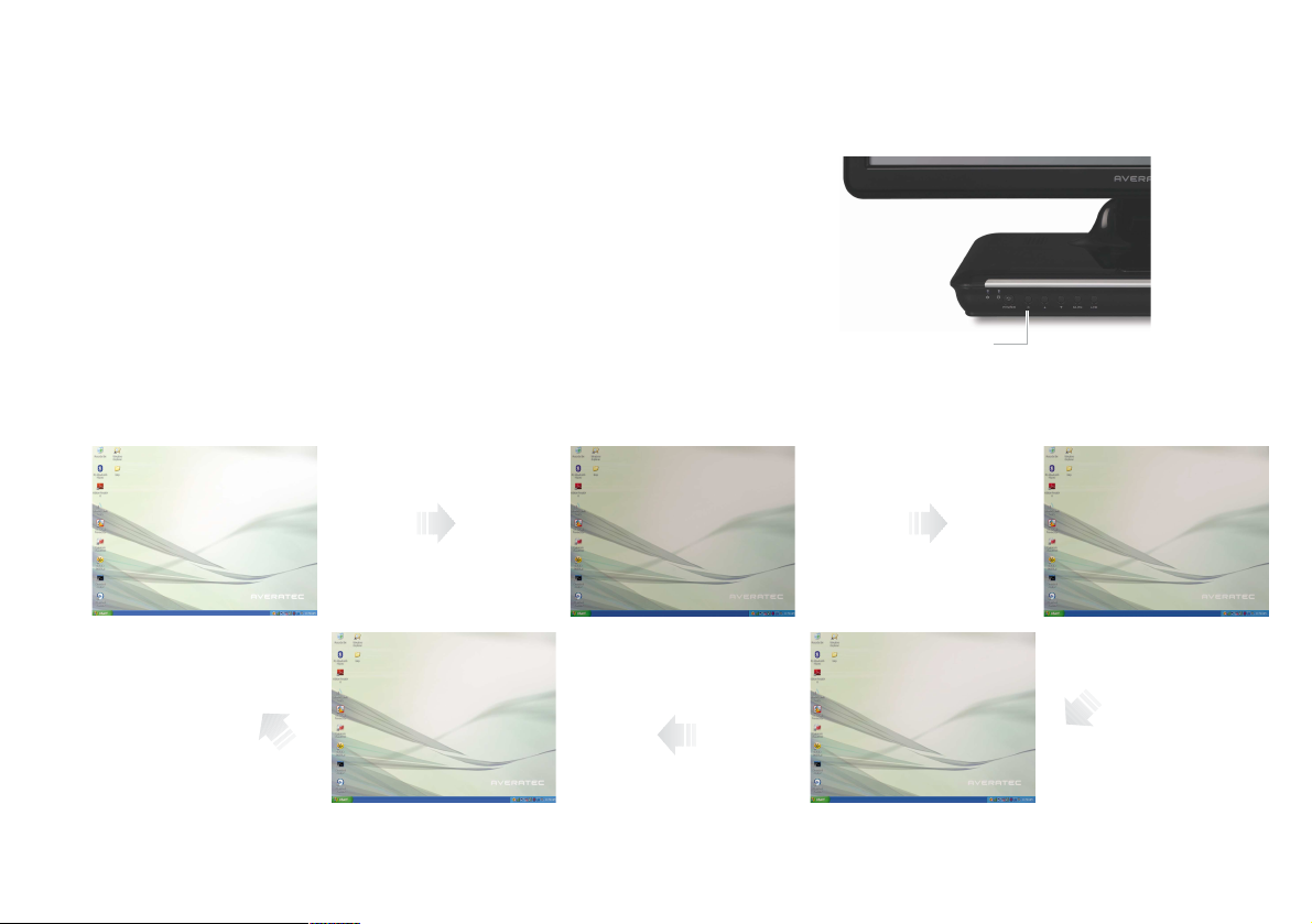
Turning On and Off
Turning on
Press the power button on the front side of the PC.
Turning off
Case 1
Click Start to turn off computer.
1. Click Start and select Turn off computer. Turn off computer screen displays.
2. Click Turn Off.
Page 17

6
Chapter 2 Getting Started
Case 2
Press the power button on the front side of the PC.
After closing all programs,the PC will be turned off. If the system is operating abnormally, you can reboot the PC
by holding down the power button until the PC turns off. Then press the power button again to boot back up.
Case 3
Power saving mode.
Saves your session and puts the computer in a lower-power state so that you can quickly resume working.
Click Stand By.
Page 18
7
Chapter 2 Getting Started
Brightness control button (toggle)
Adjusting the Brightness of the Monitor
You can adjust the brightness by clicking the brightness control button on
the front side of the PC. There are 5 levels of LCD brightness adjustment
available. Each press of the brightness control button will cycle through
each level.
100%
(full brightness level)
60% of brightness level 70% of brightness level
90% of brightness level 80% of brightness level
Using the brightness control button
Page 19
8
Chapter 2 Getting Started
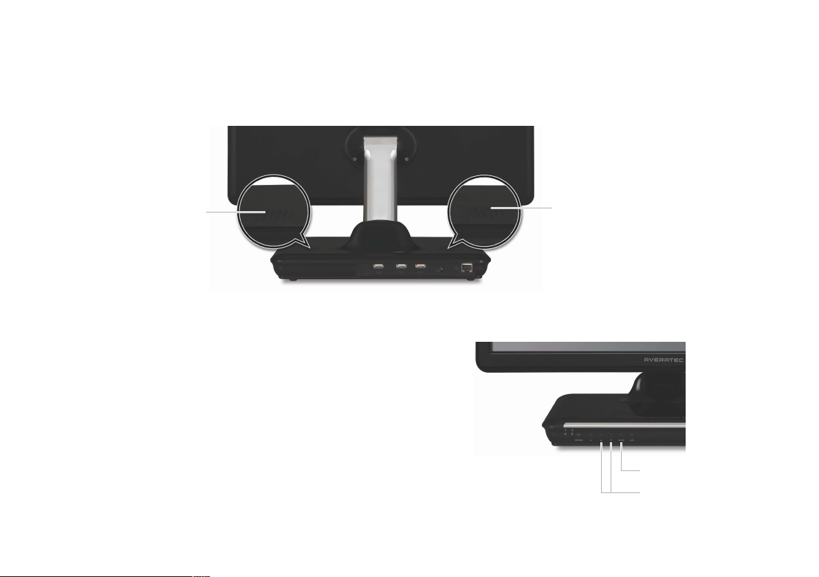
Adjusting the Speaker Volume
Speaker
Speaker
The Speaker volume level can be adjusted easily with the button located on the Front side of the PC.
Volume button (Up/Down)
To adjust the volume level, press the left volume button to increase
the volume level and the Right volume button to decrease the
volume level.
Mute button
To mute the speaker sound, press it once to enable mute and press it
again to disable mute.
Mute button
Volume button (Up/Down)
Page 20

9
Chapter 2 Getting Started
Connecting External Speakers
Connecting External Speakers
Connect the speakers to headphone jacks
Speakers (optional)
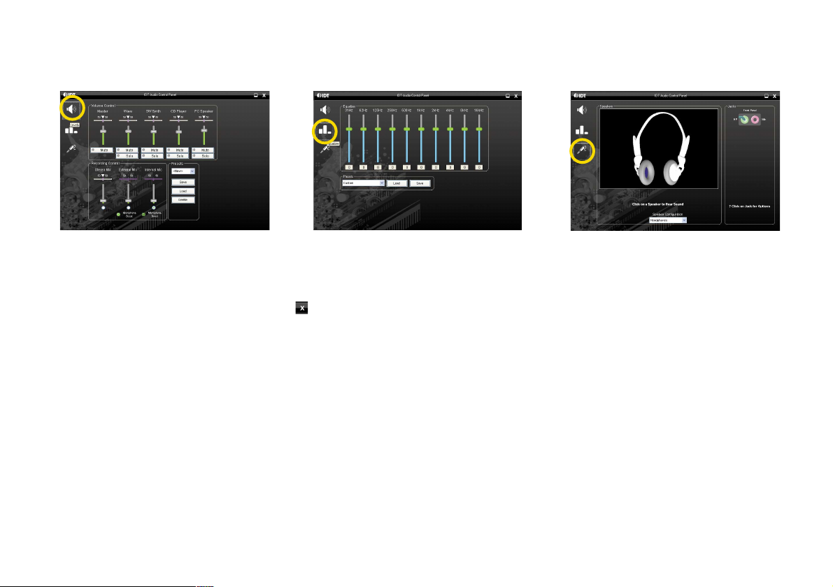
Audio control panel
To set the audio configurations, refer to the follow steps:
1. Double click the Controls IDT Audio Setting icon.
Page 21
10
Chapter 2 Getting Started
2. Set the audio configurations.
< Click theLevel icon > < Click the Equalizer icon >
< Click the Jack Setup icon >
Adjusting volume
The Averatec All-In-One PC has built-in speakers on the base of the system.You can adjust the volume by clicking the
volume adjustment buttons located on the front side of the PC and / or by using the volume control feature in Windows XP.
3. Choose which jack (Headphone or Microphone) you have your external speakers connected to. Default is the headphone
jack. When you finish the setting, click .
Page 22

11
Chapter 2 Getting Started
Using the Optical Drive
The Averatec A1 PC is fitted with a slim-tray-loading optical drive (COMBO or DVD Recorder).
Tray-loading CD drive
1. Press the Eject button of the CD/DVD drive.
2. Insert CD/DVD
Insert CD/DVD in the CD/DVD drive and place CD/DVD label upside front.
Press the CD/DVD Drive.
3. Eject CD/DVD
Press the Eject button of the CD/DVD drive on the left side of the Averatec A1 PC. You can then remove the CD/DVD.
1
2
Page 23

12
Chapter 2 Getting Started
Note
✓If you can not eject a CD/DVD from the drive, click Start, choose Computer,
right-click on the CD/DVD drive that the CD/DVD is in and choose
Eject in the
popup menu.
✓If you can not eject a CD/DVD from the drive by pressing the eject button and choosing the Eject menu, insert the paper clip
into the emergency eject hole as far as it will go then the tray will be slightly open. Pull out the tray and remove a CD/DVD from
the tray.
✓Make sure CD/DVD is not inserted upside down.(CD label side facing toward upside of PC).
✓Labels on CD/DVD may cause noise when CD/DVD drive is working. Remove labels on CD/DVD for safe use.
1
2
3
Page 24

13
Chapter 2 Getting Started
1. Press the power button and the Windows XP start screen will appear. Connect a
LAN cable to the LAN connector as shown in the figure below.
Connecting to the Internet
2. Configure the communication settings for the system based on your
communication environment. When connecting to the Internet via an
internet service provider, contact the service provider for more
information on required communication settings.
3. Launch Internet Explorer or other communication software.
Page 25

14
Chapter 2 Getting Started
You can take photos and chat with your friends.
Take photos
To take photos, follow the next steps :
1. Double click the CyberLink YouCam icon( ) on the desktop.
3. Click the Snapshot button( ) on the CyberLink YouCam screen.
2. The CyberLink YouCam will be run and a green light on the webcam LED indicates your PC is ready to take photos.
Using Your Webcam
Note
✓For more information, refer to the Help of the program. You can see the Help by clicking the help button( ) on the upper right
side of the screen.
Page 26

15
Chapter 2 Getting Started
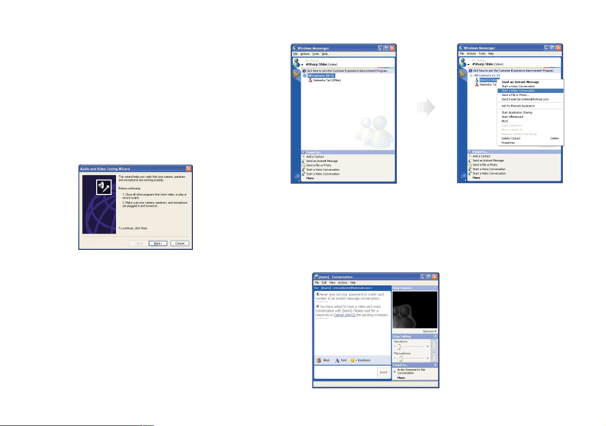
Video chatting
To chat with video, both your system and the system of the person you want to chat with must have a web camera or a
CCD camera installed. You also need to download and install a messenger program. The screen that you will see varies
depending on the type of the messenger program you’re using.
1. Run the messenger program to register your user email address. When the messenger is ready. Click Start > Windows
Messenger. Select Sign in.
Note
✓This is an example using Microsoft’s MSN Messenger. Other messenger applications may vary.
Page 27
16
Chapter 2 Getting Started
2. Right-click on your chat partner and then select
Start a Video Conversation, as illustrated below.
3. Now you’re ready to start chatting with the web camera.
Note
✓If the web-camera setting is not configured,
you will see the below screen. Run the wizard
for setting the web-camera by following the
message on the screen.
Page 28

17
Chapter 2 Getting Started
To use a wireless network in an office environment where APs (Access Points) are installed, see the following instructions.
(The example used here explains how to use the basic Windows configuration features to configure the system. You can
also use the program that comes with the wireless LAN card to configure the network.)
1. Right-click on the Wireless Network icon on the status bar, and then select View Available Wireless Networks.
Using the Wireless LAN
2. If there is an AP-enabled environment, a list of available APs will appear. Click the item you want to connect to, and click
Connect.
Page 29

18
Chapter 2 Getting Started
3. When the connected window appears, confirm the settings and then click Close.
4. Once connection is successfully established, the network icon on the status bar will indicate the status change.
Page 30

19
Chapter 2 Getting Started
Averatec's A1 PC accepts 4 types of multi-media cards into the multi-card reader slot on the right side of the PC.
Multi-Media card
SD (Secure Digital™), MS-PRO™, MS-PRO™ Duo, MS(Memory Stick™), MMC(MultiMediaCard™), RS-MMC
Inserting the multi-media card
To insert correctly, refer to the pictures. The cards are not inserted completely,
the tip of the cards will remain out of the slot. (Insert cards with label side facing
toward upside of the PC.)
Removing multi-media card
To remove the card:
1. Press the end of the card. The card will be slightly out.
2. Grip the tip of the card and take it out from the slot.
Using the Multi-Card Reader
Insert cards with label
side facing toward
upside of the PC.
MSMS-PRO
MS-PRO Duo SDMMC
RS-MMC
Page 31
20
Chapter 2 Getting Started
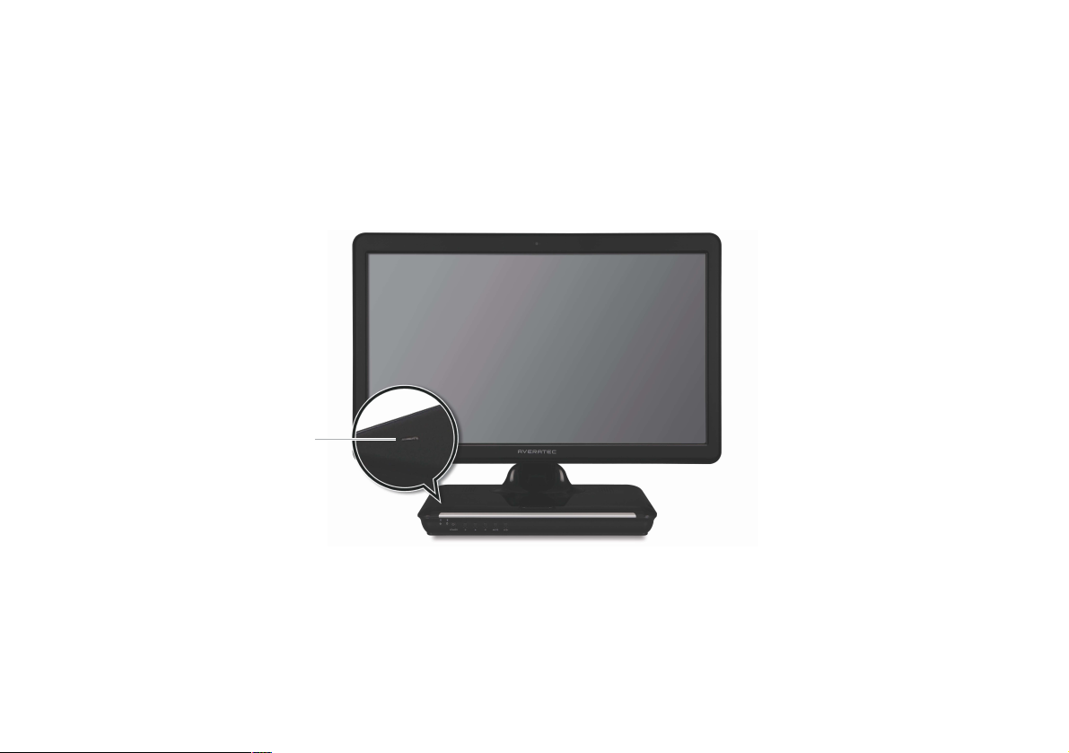
Your PC comes with a built-in internal microphone near the power button on the left of the computer. Use the built-in
internal microphone to record sound for your webcam videos, and to use instant messenger or chat software to have
video chats online.
You can use the internal microphone from a distance of up to 1.5 feet (one meter) from the Computer.
Using the Internal Microphone
Microphone
Page 32

21
Chapter 3 System BIOS SETUP
System BIOS SETUP
Chapter
3
Page 33

22
Chapter 3 System BIOS SETUP
For System BIOS Setup, only change the items that you need. Note that incorrect settings of the BIOS Setup could result in
a system malfunction.
Entering into the System BIOS Setup
After powering on the system, press <Del> to enter the System Setup screen.
BIOS Action Keys
Leaves a sub-menu to return to the previous menu OR exits the BIOS setup while saving
changes.
Shows the Sub Menu
ExitESC
Goto Sub ScreenEnter
Function Key Command Description
Shows the Help ScreenGeneral HelpF1
Saves changes and reboots the computer.Save and ExitF10
Selects the next field.Select a field<Tab>
Selects the next item.Select an item
Change value-, +
Selects the next value within a field.
Page 34

23
Chapter 3 System BIOS SETUP
BIOS Setup Menu
Main Menu
Sets most standard specifications for the system, such as the time, date.
Advanced Menu
Sets up key items related to the system’s performance.
Page 35

24
Chapter 3 System BIOS SETUP
Boot Menu
You can set the boot sequemce.
Security Menu
Sets up a password to prevent any unauthorized user from accessing
the system.
Page 36

25
Chapter 3 System BIOS SETUP
Set up Password
1. On the initial System Setup screen, Go to Change Supervisor Password, and then press <Enter>.
2. On the following screen, enter the password and then press <Enter>.
Then enter the same password again and press <Enter>.
Enter New Password Confirm New Password
3. If you entered the correct password, the following window will appear. Press <Enter>.
The Supervisor Password is at a higher level than the User Password.
This completes setting up a password.
Password installed
[OK]
Supervisor Password is
Shows the setup status of the Supervisor Password: Installed, if a upervisor Password is set, or Not Installed.
User Password is
Shows the setup status of the User Password: Installed, if a User Password is set, or Not Installed.
Change Supervisor Password
Setting up a password helps you prevent unauthorized users from accessing the system. In the factory settings, password
is Not installed. A password can have up to six alphanumeric characters and/or numbers.
Page 37

26
Chapter 3 System BIOS SETUP
Save Changes and Exit
Save the changes you have made and exit the utility.
Discard Changes
Exit the utility without saving the changes you have made.
Discard Changes
Aban your changes and reload the previous configuration before running the utilityt.
Load Optima Defaults
Select this item to load the default settings for optimal system performance.
Exit Menu
Page 38

27
Chapter 4 Expansion of the system
Expansion of the system
Chapter
4
Page 39

28
Chapter 4 Expansion of the system
Replacing the Main Memory
There may come a time when you want to expand the main memory capacity. When expanding the main memory, make
sure that the specifications of any newly replaced memory currently installed memory are the same. The following
instructions are provided to those who are familiar with system assembly/disassembly in order to help them to find the
memory specification. If you are not familiar with system assembly/disassembly or do not know your memory
specification, you should not perform the memory upgrade. Please contact customer support for assistance.
The motherboard has one SO-DIMM socket, which can accommodate up to 2.0 GB of memory. If new memory is installed,
its type, size and speed are automatically checked by the system BIOS.
The SO-DIMM socket supports the following memory specification :
200-pin DDR2 SDRAM Socket, 533/667 MHz DDR2 SDRAM Memory Interface.
The appearance of the SO-DIMM memory in the figure may not reflect the actual memory, depending on the system model.
1. Before proceeding, make sure that the system is turned off, that you are wearing an anti-static wrist strap (available in
most computer shops), and that your workspace is dust and smoke-free.
2. Removing the CD Drive and the system cover
Place the system on an open flat surface and remove the screws and back cover as shown in the figure.
Make sure that the LCD panel does not get damaged.
1
Page 40

29
Chapter 4 Expansion of the system
To fix the LCD panel, fold it until the latch snap into place as shown in the figure.
2
Spread the soft thing such as cloth over the flat surface and face down the LCD panel.
(Be careful not to damage the LCD panel.)
3
To firm the system module, insert the flat things (such as the books) between the LCD and system module.
4
To remove the CD drive, insert the flat driver into the hole and slide toward the CD drive and remove it.
5
Flat things
(such as the books)
1
1
2
3
2
Page 41

30
Chapter 4 Expansion of the system
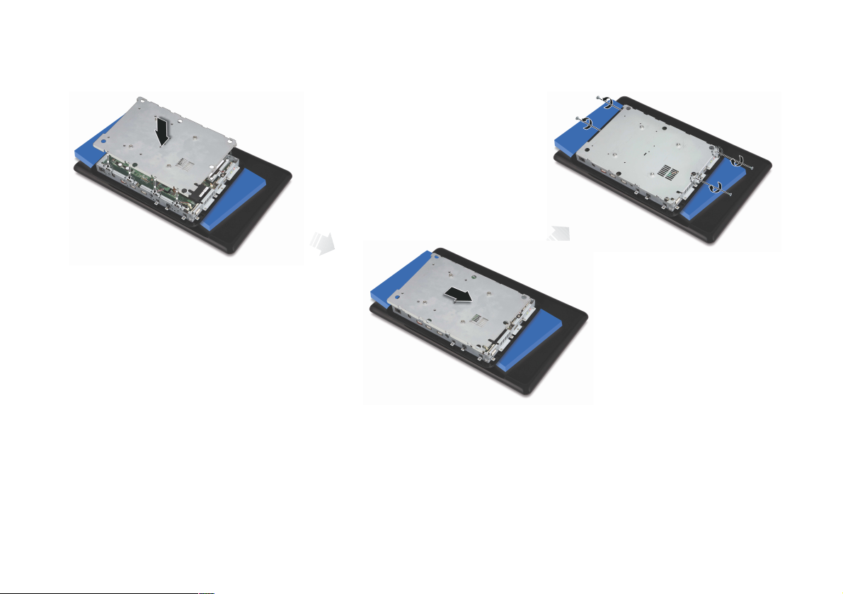
Remove the screws and system cover as shown in the figure.
6
3. Remove the screws and metal cover.
1
2
3
Page 42

31
Chapter 4 Expansion of the system
4. Replacing the main memory
To replace the memory on the socket, pull the latches on both edges of the socket away at the same time.
The memory wiill pop up about 30 degrees. Remove it from the socket.
1
Align the notches of the SO-DIMM memory with the slot keys of the socket, this allows the memory to be inserted.
Insert the memory into the socket at a slight angel (about 30 degrees) firmly, and gently press down the memory until
both latches snap into place.
2
Page 43
32
Chapter 4 Expansion of the system
5. Replace the metal cover and fix with the screws.
Page 44

33
Chapter 4 Expansion of the system
6. Replacing the system cover and the CD drive
Replace the system cover and fix with the screws.
1
Replace the CD drive and fix with the screws.
2
Page 45

34
Chapter 4 Expansion of the system
8. Checking memory capacity
Once memory installation is complete, restart the system. If an error message related to the memory capacity appears
upon booting, press the Del key to enter the system setup screen. Save the setting and exit.
7. Adjust the LCD panel for convenient using.
1
2
Page 46

35
Chapter 4 Expansion of the system
Using the Optional VESA Mount Kit
1. Turn off your system and remove all cables.
Your system has four VESA Mount holes on the bottom surface for using the optional VESA Mount kit. To use it, follow the
next steps:
2. Place LCD in down position and insert the hinge lock clip as shown below.
Hinge lock clip
Page 47

36
Chapter 4 Expansion of the system
3. Fold the LCD panel.
4. Face down the LCD panel on a soft and flat surface to locate the mounting holes on the bottom of your system.
(Be careful not to damage the LCD panel.)
5. To firm the system module, insert the flat things (such as the books) between the LCD and system module.
6. Attach the VESA Mount bracket to your system.
7. Follow the instructions in the User’s Guide that came with your VESA Mount kit.
Page 48

37
Chapter 4 Expansion of the system
Note
✓The mounting hole pattern of your system is 100 mm x 100 mm.
To purchase the optional VESA Mount kit, please refer to this size.
✓Removing the hinge lock clip
To remove the hinge lock clip, follow the next steps:
Unfold the LCD panel.
1
Push down the hinge arm slightly and remove the hinge lock clip.
2
You can adjust angel of the LCD panel.
3
1 2
Hole
Hinge arm
Page 49

38
Chapter 4 Expansion of the system
 Loading...