

Page 1
Page 2
Preface
General IntroductionsChapter 1
Chapter 2
Chapter 3
Chapter 4
Getting Started
Customizing this Notebook
BIOS Setup
Page 3

III
Regulations Information
FCC-B Radio Frequency Interference Statement
This equipment has beentestedand found to complywiththelimits for a Class B
digital device, pursuant to part 15 of the FCC rules. These limits are designed
to provide reasonable protection against harmful interference in a residential
installation. This equipment generates, uses and can radiate radio frequency
energy and, if not installed and used in accordance with the instructions, may
cause harmful interference to radio communications. However, there is no
guarantee that interference will not occur in a particular installation. If this
equipment does cause harmful interference to radio or television reception,
which can be determined by turning the equipment off and on, the user is
encouraged to try to correct the interference by one or more of the following
measures:
Reorient or relocate the receiving antenna.
Preface
Increase the separation between the equipment and receiver.
Connect the equipment into an outlet on a circuit different from that to
which the receiver is connected.
Consult the dealer or an experienced radio TV technician for help.
NOTE
1. The changes or modifications not expressly approved by the party
responsible for compliance could void the user’s authority to operate the
equipment.
2. Shield interface cables and AC power cord, if any must be used in order
to comply with the emission limits.
Page 4

IV
FCC Conditions
This device complies with part 15 of the FCC Rules. Operation is subject to the
following two conditions:
1. This device may not cause harmful interference.
2. This device must accept any interference received, including
interference that may cause undesired operation.
Preface
* For better environmental protection, waste batteries should be
collected separately for recycling or special disposal.
Page 5
V
Safety Guideline for Using Lithium Battery
pe.
(English) CAUTION: Danger of explosion if battery is incorrectly replaced.
, jos se on virheellisesti asennettu.
batteritype eller en tilsvarende type anbefalt av apparatfabrikanten.
batterityp eller en ekvivalent typ som rekommenderas av apparattillverkaren.
(Danish) ADVARSEL! Lithiumbatteri --- Eksplosionsfare ved fejlagtig
håndtering. Udskiftning må kun ske med batteri af same fabrikat og ty
Levé det brugte batteri tilbage til leverandøren.
(Deutsch) VORSICHT: Explosionsgefahr bei unsachgemäßem Austausch der
Batterie. Ersatz nur durch denselben oder einen vom Hersteller empfohlenen
gleich-wertigen Typ. Entsorgung gebrauchter Batterien nach Angaben des
Herstellers.
Replace only with the same or equivalent type recommended by the equipment
manufacturer. Discard used batteries according to manufacturer’sinstructions.
(Finnish) VAROITUS: Paristo voi räjähtää
Vaihda paristo ainoastaan valmistajan suosittelemaan tyyppiin. Hävitä käytetty
paristo valmistajan ohjeiden mukaisesti.
Preface
(French) ATTENTION: II y a danger d’ex;losion s’il y a remplacement incorrect
de la batterie. Remplacer uniquement avec une batterie du meme type ou d’un
type équivalent recommandé par le constructeur. Mettre au rebut les batteries
usages conformément aux instructions du fabricant.
(Norwegian) ADVARSEL: Eksplosjonsfare ved feilaktig skifte av batteri. Benytt
same
Brukte batterier kasseres I henhold til fabrikantens instruksjoner.
(Swedish) VARNING: Explosionsfara vid felaktigt batteribyte. Använd samma
Kassera använt batteri enligt fabrikantens instruction.
Page 6
VI
Caution on Using Modem
1. Never install telephone cables during a lightning storm.
2. Never install telephone jacks in wet locations unless the jack is specifically
designed for wet locations.
3. Never touch uninsulated telephone wires or terminals unless the telephone
line has been disconnected at the network interface.
4. Use caution when installing or modifying telephone lines.
5. Avoid using the telephone function (other than a cordless type) during an
electrical storm. There may be a remote risk of electric shock from
lightning.
6. Do not use the telephone function to report a gas leak in the vicinity of the
leak.
Preface
Optical Disc Drive Notice
CAUTION: This appliance contains a laser system and is classified as a
“CLASS 1 LASER PRODUCT.” To use this model properly, read the
instruction manual carefully and keep this manual for your future reference.
In case of any trouble with this model, please contact your nearest
“AUTHORIZED Service Center.” To prevent direct exposure to the laser
beam, do not try to open the enclosure.
Page 7
VII
Macrovision Notice
This product incorporates copyright protection technology that is protected
by U.S. patents and other intellectual property rights. Use of this copyright
protection technology must be authorized by Macrovision, and is intended
for home and other limited viewing uses only unless otherwise authorized
by Macrovision. Reverse engineering or disassembly is prohibited.
Safety Instructions
1. Read the safety instructions carefully and thoroughly.
2. Save this User Guide for possible use later.
3. Keep this equipment away from humidity and high temperature.
4. Lay this equipment on a stable surface before setting it up.
Preface
5. The openings on the enclosure are used for air convection and to prevent
the equipment from overheating. Do not cover the openings.
6. Make sure that the power voltage is within its safety range and has been
adjusted properly to the value of 100~240V before connecting the
equipment to the power inlet.
7. Place the power cord in a way that people are unlikely to step on it. Do
not place anything on the power cord.
8. Always unplug the power cord before inserting any add-on card or module.
9. All cautions and warnings on the equipment should be noted.
10. If any of the following situations arises, get the equipment checked by a
service personnel:
Page 8

VIII
The power cord or plug is damaged.
Liquidhas penetrated into the equipment.
The equipment has been exposed to moisture.
The equipment has not worked well or you can not get it work
according to User’s Manual.
The equipment was dropped and damaged.
The equipment has obvious signs of breakage.
11. Neverpour any liquid into the opening that could damage the equipment or
cause an electrical shock.
12. Do not leave the equipment in an unconditioned environment with a
storage temperature of 60OC (140OF) or above, which may damage the
equipment.
13. To prevent explosion caused by improper battery replacement, use the
same or equivalent type of battery recommended by the manufacturer only.
Preface
Page 9
IX
WEEE Statement
(English) Under the European Union ("EU") Directive on Waste Electrical and
Electronic Equipment, Directive 2002/96/EC, which takes effect on August 13,
2005, products of "electrical and electronic equipment" cannot be discarded as
municipal waste anymore and manufacturers of covered electronic equipment
will be obligated to take back such products at the end of their useful life.
(Deutsch) Gemäß der Richtlinie 2002/96/EG über Elektro- und
Elektronik-Altgeräte dürfen Elektro- und Elektronik-Altgeräte nicht mehr als
kommunale Abfälle entsorgt werden, die sich auf 13.August, 2005 wirken. Und
der Hersteller von bedeckt Elektronik-Altgeräte gesetzlich zur gebrachten
Produkte am Ende seines Baruchbarkeitsdauer zurückzunehmen.
(Français) Au sujet de la directive européenne (EU) relative aux déchets des
Preface
équipement électriques et électroniques, directive 2002/96/EC, prenant effet le
13 août 2005, que les produits électriques et électroniques ne peuvent être
déposés dans les décharges ou tout simplement mis à la poubelle. Les
fabricants de ces équipements seront obligés de récupérer certains produits en
fin de vie.
(Русский) В соответствии с директивой Европейского Союза (ЕС) по
предотвращению загрязнения окружающей среды использованным
электрическим и электронным оборудованием (директива WEEE
2002/96/EC), вступающей в силу 13 августа 2005 года, изделия,
относящиеся к электрическому и электронному оборудованию, не могут
Page 10
X
Preface
рассматриваться как бытовой мусор, поэтому производители
вышеперечисленного электронного оборудования обязаны принимать его
для переработки по окончании срока службы.
(Español) Bajo la directiva 2002/96/EC de la Unión Europea en materia de
desechos y/o equipos electrónicos, con fecha de rigor desde el 13 de agosto
de 2005, los productos clasificados como "eléctricos y equipos electrónicos"
no pueden ser depositados en los contenedores habituales de su municipio,
los fabricantes de equipos electrónicos, están obligados a hacerse cargo de
dichos productos al termino de su período de vida.
(Nederlands) De richtlijn van de Europese Unie (EU) met betrekking tot
Vervuilingvan Electrische en Electronische producten (2002/96/EC), die op 13
Augustus 2005 in zal gaan kunnen niet meer beschouwd worden als vervuiling.
Fabrikanten van dit soort producten worden verplicht om producten retour te
nemen aan het eind van hun levenscyclus..
(Srpski) Po Direktivi Evropske unije ("EU") o odbačenoj ekektronskoj i
električnoj opremi, Direktiva 2002/96/EC, koja stupa na snagu od 13. Avgusta
2005, proizvodi koji spadaju pod "elektronsku i električnu opremu" ne mogu
više biti odbačeni kao običan otpad i proizvođači ove opreme biće prinuđeni da
uzmu natrag ove proizvode na kraju njihovog uobičajenog veka trajanja.
(Polski) Zgodnie z Dyrektywą Unii Europejskiej ("UE") dotyczącąodpadów
produktów elektrycznych i elektronicznych (Dyrektywa 2002/96/EC), która
wchodzi w życie 13 sierpnia 2005, tzw. “produkty oraz wyposażenie
elektryczne i elektroniczne " nie mogąbyćtraktowane jako śmieci komunalne,
tak więc producenci tych produktów będązobowiązani do odbierania ich w
Page 11
XI
momencie gdy produkt jest wycofywany z użycia.
(TÜRKÇE) Avrupa Birliği (AB) Kararnamesi Elektrik ve Elektronik Malzeme
Atığı, 2002/96/EC Kararnamesi altında 13 Ağustos 2005 tarihinden itibaren
geçerli olmak üzere, elektrikli ve elektronik malzemeler diğer atıklar gibi çöpe
atılamayacak ve bu elektonik cihazların üreticileri, cihazların kullanım süreleri
bittikten sonra ürünleri geri toplamakla yükümlü olacaktır.
(ČESKY) Podle směrnice Evropské unie ("EU") o likvidaci elektrických a
elektronických výrobků2002/96/EC platné od 13. srpna 2005 je zakázáno
likvidovat "elektrické a elektronické výrobky" v běžném komunálním odpadu a
výrobci elektronických výrobků, na které se tato směrnice vztahuje, budou
povinni odebírat takové výrobky zpět po skončení jejich životnosti.
(MAGYAR) Az Európai Unió („EU") 2005. augusztus 13-án hatályba lépő, az
elektromos és elektronikus berendezések hulladékairól szóló 2002/96/EK
irányelve szerint az elektromos és elektronikus berendezések többé nem
Preface
kezelhetőek lakossági hulladékként, és az ilyen elektronikus berendezések
gyártói kötelessé válnak az ilyen termékek visszavételére azok hasznos
élettartama végén.
(Italiano) In base alla Direttiva dell’Unione Europea (EU) sullo Smaltimento dei
Materiali Elettrici ed Elettronici, Direttiva 2002/96/EC in vigore dal 13 Agosto
2005, prodotti appartenenti alla categoria dei Materiali Elettrici ed Elettronici
non possono più essere eliminati come rifiuti municipali: i produttori di detti
materiali saranno obbligati a ritirare ogni prodotto alla fine del suo ciclo di vita..
Page 12
XII
Trademarks
All trademarks are the properties of their respective owners.
Microsoft is a registered trademark of Microsoft Corporation.
Windows®98/ME, 2000/XP are registered trademarks of Microsoft
Corporation.
Sempron™ and Turion™ are registered trademarks of AMD in the
United States and other countries.
AMI®is a registered trademark of American Megatrends Inc.
PCMCIA and CardBus are registered trademarks of the Personal
Notebook Memory Card International Association.
Release History
Preface
Version Revision Note Date
1.0 Initial Release December, 2005
1.2 Production Release February, 2006
Page 13
XIII
Table of Contents
Preface
Regulations Information.................................................................................II
FCC-B Radio Frequency Interference Statement ......................................II
FCC Conditions........................................................................................III
Safety Guideline for Using Lithium Battery................................................. IV
Caution on Using Modem .............................................................................. V
Optical Disc Drive Notice .............................................................................. V
Macrovision Notice ..................................................................................... VI
Safety Instructions........................................................................................ VI
WEEE Statement......................................................................................... VIII
Trademarks ................................................................................................... XI
Preface
Release History............................................................................................. XI
Introductions
How to Use This Manual..............................................................................1-2
Unpacking ....................................................................................................1-4
Page 14

XIV
Getting Started
Specification ................................................................................................2-2
Product View................................................................................................2-6
Top-open View.......................................................................................2-6
Front View..............................................................................................2-9
Right-side View....................................................................................2-11
Left-side View ......................................................................................2-13
Rear View ............................................................................................2-14
Bottom View.........................................................................................2-15
Power Management ...................................................................................2-16
AC Adapter ..........................................................................................2-16
Battery Pack ........................................................................................2-18
Using the Battery Pack.........................................................................2-21
Memory Module Installation......................................................................2-23
Preface
Installing Memory Module Process...............................................................2-23
Basic Operations .......................................................................................2-27
Safety and Comfort Tips.......................................................................2-27
Have a Good Work Habit .....................................................................2-28
Knowing the Keyboard.........................................................................2-29
Knowing the Touchpad.........................................................................2-34
About Hard Disk Drive..........................................................................2-38
Using the Optical Disc Drive.................................................................2-39
Page 15
XV
Customizing this Notebook
Connecting the External Devices................................................................3-2
Connecting the Peripheral Devices ........................................................3-3
Connecting the Communication Devices................................................3-6
PC Card Installation.....................................................................................3-7
Installing the PC card.............................................................................3-7
Removing the PC card...........................................................................3-8
Express Card Installation ............................................................................3-9
Installing the Express card .....................................................................3-9
Removing the Express card ...................................................................3-9
Safely Remove Hardware ..........................................................................3-10
BIOS Setup
Preface
About BIOS Setup........................................................................................4-2
When to Use BIOS Setup.......................................................................4-2
How to Run BIOS Setup ........................................................................4-2
Control Keys ..........................................................................................4-3
BIOS Setup Menu.........................................................................................4-4
Main menu.............................................................................................4-5
Advanced menu.....................................................................................4-7
Boot menu .............................................................................................4-9
Security menu......................................................................................4-10
Exit menu.............................................................................................4-12
Page 16

Preface
General IntroductionsChapter 1
Chapter 2
Chapter 3
Chapter 4
Getting Started
Customizing this Notebook
BIOS Setup
Page 17

1-2
General Introductions
Congratulations on your purchase of an Averatec notebook. We are proud to
tell our customers that this notebook has been thoroughly tested andcertified for
unsurpassed dependability, quality and customer satisfaction.
How to Use This Manual
This User’s Manual provides instructions and illustrations on how to operate your
notebook. It is recommended to read this manual carefully before using the
notebook.
Chapter 1, General Introductions, includes the descriptions of all accessories
included with the notebook. It is recommended to check that you have received
all of the accessories when you first open the packing box. If any item is
damaged or missing, please contact the store or reseller where you purchased
this notebook.
Chapter 2, Getting Started, provides the specifications of the notebook, and
introduces the function buttons, quick launch buttons, connectors, LEDs and the
basic operations of using this notebook. This chapter also includes the correct
procedure of installing and uninstalling the battery pack.
Page 18
1-3
General Introductions
Chapter 3, Customizing your Notebook, includes instructions on connecting
accessories external to the notebook, including: mice, keyboard, webcam,
printer, external monitor, IEEE 1394 (FireWire) devices, and communication
devices. Also included are installation and removal instructions for third-party
PC card devices.
Chapter 4, BIOS setup, provides information on the BIOS Setup program that
allows you to configure your notebook for optimum use.
Page 19

1-4
General Introductions
Unpacking
Unpack the shipping carton and check all items carefully. If any item is
damaged or missing, please contact the store or reseller that you bought the
notebook from immediately. Keep the box and all packing materials in case you
need to ship the unit in the future.
The shipping carton should contain the following items:
Notebook computer
Quick Start Guide
Phoenix Recovery Brochure
High-capacityLi-ion battery pack
AC adapter and power cord
These accessories listed above may change without notice.
Page 20
Preface
General IntroductionsChapter 1
Chapter 2
Chapter 3
Chapter 4
Getting Started
Customizing this Notebook
BIOS Setup
Page 21
2
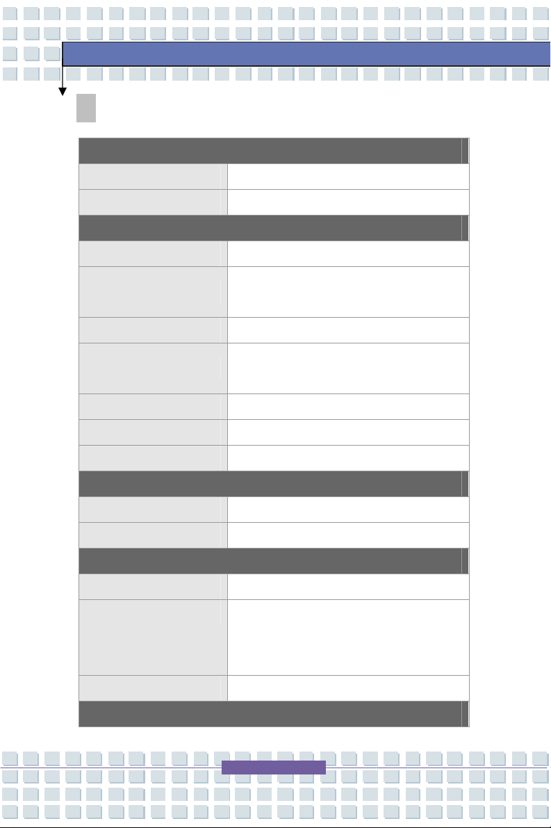
Specifications
Physical Characteristic
Dimension 15.5”(L) x 10.9”(D) x 1” ~ 1.37”(H)
Weight approx. 7.2 lbs.
CPU
Processor Type 754-pin (uPGA)
Getting Started
Support Processor
L1 Cache 128K (Turion); 64K (Sempron)
L2 Cache
FSB Speed 800MHz Double Clock
Socket Socket N (754-pin)
Smart Power Management AMD Power Now
Mobile Turion 64 25/35W series, Sempron
25W series model dependent
Turion: 512KB/1MB
Sempron: 128/256KB model dependent
Core Chips
North Bridge ATIRS482M
South Bridge ATISB450 (ATI RADEON Xpress 200M)
Memory
Technology DDR 333/400
Memory DDR SO-DIMM X 2 slot, supports
128/256/512/1024MB DDR333 SO-DIMM
PC2700
Maximum 2GB(1G DDR SO-DIMM X 2)
Power
Page 22
Getting Started
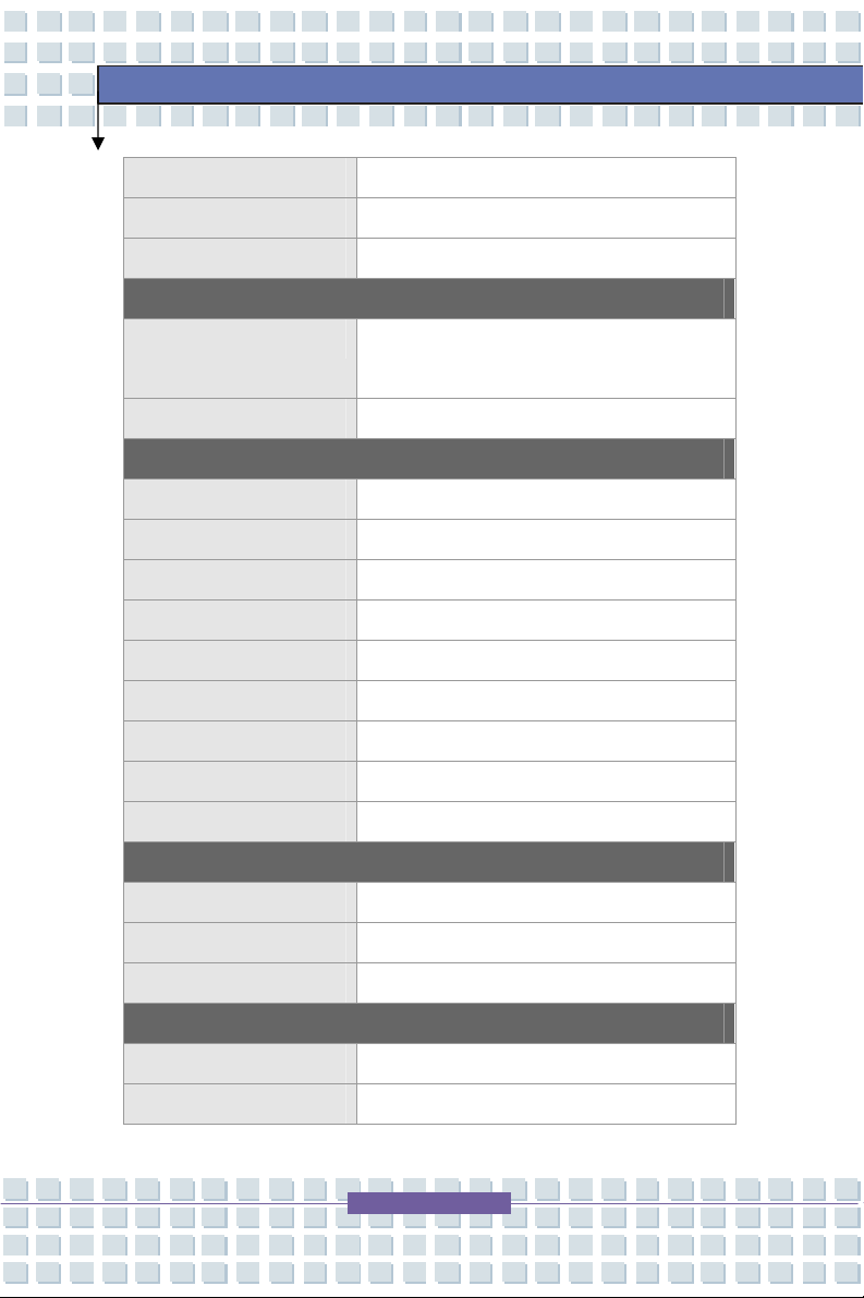
AC Adapter 90W, 19 Volt
Battery Pack 6 cells standard - 4400mAH
RTC Battery Yes, 3 years
Storage
HDD form factor 2.5mm(H), 80/100GB UDMA 100 [4200 &
5400 rpm - model dependent]
Optical Device Dual Layer DVD Burner
I/O Port
Monitor DB 15-PIN External VGA CRT/LCD
USB x 3 (USB version 2.0)
Line-in x 1
Mic-in x 1
Headphone/SPDIFOut x 1 (SPDIF-Out supported)
RJ11 x 1
RJ45 x 1
IEEE FIREWIRE 1394 Firewire x 1
TV-Out x 1 (S-Video)
Communication Port
56K Fax/MODEM MD560LMI-2 (AZALIA I/F)
LAN 10/100/1000 Gigabit
Wireless LAN IEEE 802.11b/g MSI 6833(B)
CARD SLOTS
PC Express x 1
PCMCIA TypeII x 1
Page 23
Getting Started
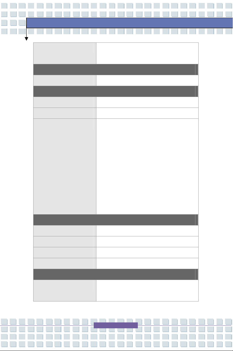
Memory Cards 5-in-1 Card Reader
(xD/MS/MS PRO/MMC/SD)
Display
LCD Type 17” WXGA +/ WSXGA+ with AveraBrite™
Video
Controller ATI RS482M
VRAM 128MB shared video memory
LCD Support 1800 x 1440, 32 bit color
1600 x 1200, 32 bit color
1440 x 900, 32 bit color – native resolution
1400 x 1050, 32 bit color
1280 x 1024, 32 bit color
1152 x 1768, 32 bit color
1024 x 768, 32 bit color
800 x 600, 32 bit color
640 x 480, 32 bit color
Audio
Sound Controller ATI SB450 (AZALIA)
Sound Codecchip RealtekALC882H
Internal Speaker 2Speakers
SoundBlaster SoundBlaster compatible (No DOSsupport)
Software & BIOS
Support OS Win XP Home, Professional and Media
Center Editions
Page 24
BIOS Fast Boot Support --- Yes (Win XP)
Security
Kensington Lock Hole x 1
Getting Started
Page 25
Getting Started
Product Overview
This section provides you with the description of all the basic aspects of your
Notebook. It will help you to know more about your Notebook before using it.
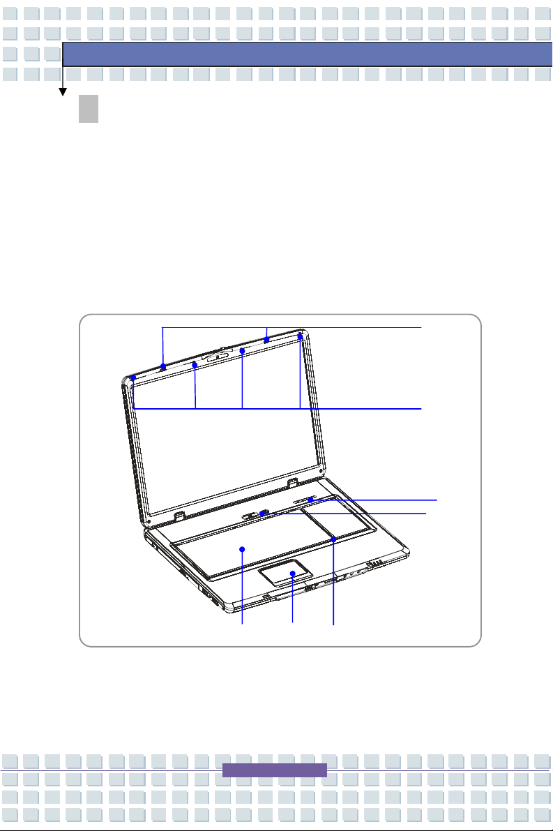
Top-open View
Press the Cover Latch to open the top cover (LCD Panel). The top-open view
and descriptions follow below.
Page 26

1. Cover Latch
This latch will lock the LCD cover with the main system when closing your
Notebook PC.
2. Rubber Pads
Protects your Notebook PC when closing the LCD cover.
3. Power Button
Power Button: To turn your Notebook power ON and
OFF.
4. Keyboard
The built-in keyboard provides all the functions of a full-sized 103-key
(US-defined) keyboard.
5. Touchpad
It is the pointing device of the computer.
6. Internal Microphone
Getting Started
This is the built-inmicrophone.
Page 27

7. Status LED’s
Getting Started
Num Lock: Glowing Blue when the Num Lock function is
activated.
Caps Lock: Glowing Blue when the Caps Lock function is
activated.
Scroll Lock: Glowing Blue when the Scroll Lock function is
activated.
Hard Disk In-use: Glowing Blue when the Notebook PC is
accessing the hard disk drive.
Page 28

Front View
1. Cover Latch (External View)
Press Cover Latch to the right and lift the cover.
2. IEEE 1394 FIREWIRE
The IEEE 1394 FireWire port is a high-speed bus that allows you to connect
high-end digital devices such as digital video cameras, camcorders, etc. for
high speed file transfer.
Getting Started
3. Audio Port Connectors
Supports high quality stereo Hi-Fi sound
.
Headphones:A connector for
externalspeakers or headphones.
Line In:Used for an external audio
device.
Microphone: Used to connect an
external microphone.
Page 29

4. Status LED
Battery: Glowing Green when recharging.
Battery LED goes out when recharging is complete or when
the AC adapter is disconnected.
Glowing Orange when the battery is in low battery status.
Blinking Orange if the battery is no longer operating correctly
and needs to be replaced.
Power On/ Off/ Suspend: Blinking Red when the system is
in suspend mode; LED goes off when the system is activated
and in the On mode, and turned off.
1. Wireless LAN: 1.Glowing Green when the wireless LAN
function is enabled. LED goes out when wireless LAN
function is disabled.
5. 5 in 1 Memory Card Reader
Getting Started
The built-in card reader supports MMC (multi-media card), MS
(memory stick) , MS Pro, SD and xD memory cards.
Page 30

Right-side View
1. Express Card Slot
The computer provides an Express Card slot. The new Express
Card interface is smaller and faster than the PC Card (PCMCIA)
interface. The Express Card technology takes advantage of the
scalable, high-bandwidth serial PCI Express and USB 2.0 interfaces.
Getting Started
2. PC Card Slot (PCMCIA)
The computer provides a PC card slot to support one Type-II PC card for
expansion functions, such as LAN/WLAN, WWAN/WMAX, EVDO/Edge,
memory card, etc.
3. USB Port
The USB 2.0 port allows you to connect USB-interface peripheral devices,
such as external mouse, keyboard, portable hard disk dri, printer and more.
4. S-Video Connector
By using a Super VHS (S-Video) cable, this connector allows you to
connect a television (NTSC/PALsystem) to use as a computer display.
Page 31

5. System Vents
The system vents are designed to cool the system. DO NOT block the
ventilator as this blocks air circulation.
6. External CRT/VGA Port
The 15-pin D sub VGA port allows you to connect an external CRTmonitor,
or LCD other standard VGA-compatible device (such as a projector).
Getting Started
Page 32

Left-side View
1. USB Ports
The USB 2.0 port allows you to connect USB-interface peripheral devices,
such as external mouse, keyboard, portable hard disk drives, printer and
more.
2. Optical Disc Drive
This notebook supports a CD/DVD+/-RW with Dual Layer burning. The
Getting Started
optical device allows you to use a CD/DVD disc for installing software,
accessing data and playing music and movies on the computer.
Page 33

Rear View
1. Kensington Lock
This port is used to lock the computer to a specific locationwith a cable that
supports the Kensington lock.
2. Power Connector
Connects theAC adapter and external power to the computer.
3. RJ-11 Connector
The computer provides a built-in modem that allows you to connect a
Getting Started
telephone line through this connector. Use the RJ-11 connector and
the 56K V.90 modem to make a dial-up connection.
4. RJ-45 Connector
The 10/100/1000 Ethernet Gigabit connector is used to connect a LAN
cable for network connection.
5. Vent Ports
The vent ports are designed to cool the system. DO NOT block these.
6. Battery Pack (Rear View)
To supply power to computer when the AC adapter is not connected.
Page 34

Bottom View
Getting Started
1. Battery Release Lever
The battery release lever is used to remove the battery pack from the
system. Press the lever with one hand and pull the battery pack out
carefully with the other hand.
2. Battery Lock/Unlock Switch
The battery cannot be removed when the switch is positioned in the
locked position. Once the switch is moved to the unlocked position,
the battery is removable.
3. Battery Pack
Supplies power to your computer when the AC adapter is not connected.
Page 35

Getting Started
Power Management
AC Adapter
Please note that it is strongly recommended to connect the AC adapter and use
the AC power while using your Notebook for the first time. When the AC
adapter is connected, the battery will be charging immediately.
Note that the AC adapter included in the package is approved for your Notebook;
using a different AC adapter may damage the Notebook or other devices
connected to the notebook.
Connecting the AC Power
1. Unpack the package to find the AC adapter and power cord.
2. Attach the power cord to the connector of the AC adapter.
3. Plug the DC end of the adapter to the Notebook, and the male end
of the power cord to the electrical outlet.
Page 36

Disconnecting the AC Power
When you disconnect the AC adapter, you should:
1. Unplug the power cord from the electrical outlet first.
2. Unplug the connector from the Notebook.
3. Disconnect the power cord and the connector of AC adapter.
4. When unplugging the power cord, always hold the connector part of
the cord. Never pull the cord directly!
Getting Started
Page 37

Getting Started
Battery Pack
This Notebook is equipped with a high-capacity Li-ion Battery pack. The
rechargeable Li-ion battery pack provides internal power source of the Notebook.
A fully charged battery pack can supply power to the Notebook approximately up
to 2 hours. Battery life will vary depending on your usage.
Removing the Battery Pack
1. Make sure the computer is turned off.
2. Check that the Lock/Unlock Lever is in the Unlocked position.
3. Locate the Battery Release Switch on the bottom side.
4. Push the Release Switch in the direction of arrow the showing below
the button.
5. Slide the left side of the battery pack first out of the compartment and
then pull out the right side of the battery pack.
Page 38

Getting Started
Page 39

Replacing the Battery Pack
1. Insert the right side of battery pack into the compartment.
2. Slightly slide and press the battery pack into place.
3. After the right side of the battery pack fits into the right track, then
slightly press the left side of battery pack into the battery chamber.
4. Make sure the Lock/UnlockSwitch is in the Locked position.
Getting Started
Warning
1. Do not try to disassemble THE BATTERY PACK.
2. Please follow your local laws and regulations to recycle the
battery pack.
Page 40

Getting Started
Using the Battery Pack
Battery Safety Tips
Replacing or handling the battery incorrectly may present a risk of fire or
explosion, which could cause serious injury.
Only replace the main battery pack with the same or equivalent type of
battery.
Do not disassemble, short-circuit or incinerate batteries or store them to
temperatures above +60° C (+140° F).
Do not tamper with batteries. Keep them away from children.
Do not use rusty or damaged batteries.
Dispose of batteries according to local regulations. Check with your
local solid waste officials for details about recycling options or for proper
disposal in your area.
Conserving Battery Power
Efficient battery power is critical to maintain a normal operation. If the battery
power is not managed well, the saved data and customized settings may be lost.
Follow these tips to help optimize battery life and avoid a sudden power loss:
Suspend system operation if the system will be idle for a while or
shorten the Suspend Timer’s timeto activate period.
Turn off the system if you won’t be using it for a period of time.
Disable unneeded settings or remove idle peripherals to conserve
power.
Connect an AC adapter to the system whenever possible.
Page 41

Getting Started
Charging the Battery Pack
The battery pack can be recharged while it is installed in the Notebook. Please
pay attention to the following tips before recharging the battery:
If a charged battery pack is not available, save your work and close all
running programs and shut down the system or Save-to-Disk.
Plug in the external AC poweradapter.
You can use the system, suspend system operation or shut down and
turn off the system without interrupting the charging process.
The battery pack uses Lithium-ion battery cells that have no “memory
effect.” You do not need to discharge the battery pack before you
begin charging. However, to optimize the life of battery, we suggest
that consuming the battery power completely once a month is
necessary.
If you do not use the Notebook for a long time, it is suggested to remove
the battery pack from your Notebook. This may be helpful to extend
your batteries life.
The actual charging time will be determined by the applications in use.
Page 42

Memory Module Installation
1. Memory Module Compartment
Getting Started
Page 43

Installing Memory module process
1. Align the memory module in the DIMM socket. There are 2 DIMM
sockets on the system motherboard.
Getting Started
Warning
The memory module can only fit in one direction due to the keyed
notch. Wrong orientation will cause improper installation and may
damage the memory module or DIMM socket.
Page 44

Getting Started
2. Gently push down on the memory module until the metal-locking levers
on each side of the DIMM socket is fastened.
Page 45

Getting Started
3. If you have more than one memory module, align the 2ndmemory module
to the empty DIMM socket.
Page 46

Getting Started
4. Gently push down on the memory module until the metal-locking levers
on each side of the DIMM socket is fastened.
Page 47

Getting Started
Basic Operations
If you are a beginner to Notebooks, please read the following tips to make
yourself safe and comfortable during the operations.
Safety and Comfort Tips
The Notebook is a portable computing platform that allows you to work anywhere.
However, choosing a good workspace is important if you have to work with your
Notebook for long periods of time.
Your work area should have enough illumination.
Choose the proper desk and chair and adjust their height to fit your
posture when operating.
When sitting on a chair, adjust the chair’s back (if available) to support
your back comfortably.
Place you feet flat and naturally on the floor, so that your knees and
elbows have the proper position (about 90-degree) when operating.
Put your hands on the desk naturally to support your wrists.
Adjust the angle/position of the LCD panel, so that you have the optimal
view.
Avoid using your Notebook in a space where it may cause you
discomfort.
The Notebook is an electrical device, please treat it with great care to
avoid personal injury.
Page 48

Getting Started
Please keep the following tips in mind when operating.
Change your posture frequently.
Stretch and exercise you body regularly.
Remember to take breaks after working for a period of time.
Knowing the Keyboard
The Notebook’s keyboard provides all the functions of a full-sized 103-key
keyboard and the additional Fn keys for specific functions on the Notebook.
The keyboard can be divided into four categories: Typewriter keys, Cursor
keys, Numeric keys and Function keys.
Page 49

Getting Started
Typewriter Keys
Typewriter Keys
The function of the Typewriter keys is the major function of the keyboard, which
is similar to the keys on a typewriter. It also provides several keys for special
purposes, such as the [Ctrl], [Alt] and [Esc] key.
When the “lock keys” are pressed, the corresponding LED’s will light up to
indicate their status:
Num Lock: Press and hold the [Fn] key and press the Num Lock key to
toggle the Num Lock on and off. When this function is activated, you can
use the numeric keys that are includedin the numeric keypad.
Caps Lock: Press this key to toggle the Caps Lock on and off. When this
function is activated, the letters you type are kept in uppercase.
Scroll Lock: Press and hold the [Fn] key and press the Scroll Lock key to
toggle the Scroll Lock on and off. This function is defined by individual
programs, and it is usually used under DOS.
Page 50

Cursor Keys
The keyboard provides four cursor
(arrow) keys and [Home], [PgUp], [PgDn],
Getting Started
[End] keys at the lower right corner,
which are used to control the cursor
movement.
Move the cursor left for one space.
Move the cursor right for one space.
Move the cursor up for one line.
Move the cursor down for one line.
Move to the previous page.
Move to the next page.
Cursor
Keys
Move to the beginning of the line (or document).
Move to the end of the line (or document).
Page 51

Getting Started
The Backspace key, [Ins] and [Del] keys at upper right corner are typically used
for editing purposes.
This key is used to switch the typing mode between
“insert” and “overtype” modes.
Press this key to delete one character to the right of the
cursor and move the following text left for one space.
Press this key to delete one character to the left of the
cursor and move the following text left for one space.
Numeric Keys
The keyboard provides a dedicated numeric
keypad. When the Num Lock is activated,
you can use these numeric keys to enter
numbers and calculations. Otherwise, they
are used to control cursor movement.
Page 52

Function Keys
Windows Keys
You can find the Windows Logo key ( ) and Application Logo key ( )
on the keyboard, which are used to perform Windows-specific functions,
such as launching the Start and shortcut menus. For more information on
these two keys, please refer to your Windows manual or online help.
[Fn] Key
Switch the display output mode between the
+
LCD, external monitor or Both.
Getting Started
+
+
+
+
+
+
+
Disable/enable Touchpad.
Decrease the LCD brightness.
Increase the LCD brightness.
Decrease the built-in speaker’s volume.
Increase the built-in speaker’s volume.
Disable the Notebook’s audio function.
Force the Notebook into suspend mode
(depending on the system configuration).
Page 53

Getting Started
Knowing the Touchpad
The integrated touchpad in your Notebook is a pointing device that is compatible
with standard mouse, allowing you to control the Notebook by pointing the
location of the cursor on the screen and making selections with its two buttons.
1. Cursor Movement Area
This pressure-sensitive area of the touchpad, allows you to place your
finger on it and control the cursor on the screen by moving your finger.
2. Right Button
Acts as the mouse’s right button.
3. Left Button
Acts as the mouse’s left button.
Page 54

Using the Touchpad
Read the following description to learn how to use the touchpad:
Positioning and Moving
Place your finger on the touchpad (usually using the forefinger), and the
rectangular pad will act as a miniature duplicate of your display. When
you move your fingertip across the pad, the cursor on the screen will move
simultaneously in the same direction. When your finger reaches the edge
of the pad, lift your finger and replace it on a proper location of the
touchpad.
Point and Click
When you have moved and placed the cursor over an icon, a menu item or
a command that you want to execute, simply tap slightly on the touchpad or
press the left button to select. This procedure, called point and click, is
the basics of operating your Notebook. Unlike the traditional pointing
Getting Started
device such as the mouse, the whole touchpad can act as a left button, so
that each tap on the touchpad is equivalent to pressing the left button.
Tapping twice more rapidly on the touchpad is to execute a double-click.
Drag and Drop
You can move files or objects in your Notebook by using drag-and-drop.
To do so, place the cursor on the desired item and slightly tap twice on the
touchpad, and then keep your fingertip in contact with the touchpad on the
second tap. Now, you can drag the selected item to the desired location
by moving your finger on the touchpad, and then lift your finger from the
touchpad to drop the item into place. Alternately, you can press and hold
the left button when you select an item, and then move your finger to the
Page 55

desired location; finally, release the left button to finish the drag-and-drop
operation.
Configuring the Touchpad
You can customize the pointing device to meet your personal needs. For
example, if you are a left-hand user, you may want to swap the functions of
the two buttons. In addition, you can change the size, shape, moving
speed and other advanced features of the cursor on the screen.
To configure the touchpad, you can use the standard Microsoft or IBM PS/2
driver in your Windows operating system. The Mouse Properties in
Control Panel allow you to change the configuration. If you prefer to use
an external mouse, Use the [Fn] + F2 keys to disable the cursor.
Getting Started
Page 56

Getting Started
About The Hard Disk Drive
Your Notebook is equipped with a high-speed 2.5-inch IDE (Integrated Drive
Electronics) hard disk drive. The hard disk drive is a storage device with much
higher speed and larger capacity than other storage devices, such as a floppy
disk drive and optical storage devices. It is used to install the operatingsystem
and software applications.
1. To avoid unexpected data loss in your system, please backup
your critical files regularly.
2. Do not turn off the Notebook when the Hard Disk In-use LED
is on.
3. Do not remove or install the hard disk drive when the
Notebook is turned on. The replacement of the hard disk
drive should only be done by an authorized retailer or service
representative.
Page 57

Getting Started
Using the Optical Disc Drive
Your Notebook is equipped with an optical storage device, which is known as the
DVD Dual Layer drive.
DVD Dual Drive: A dual format recorder, allows you to record both the
+R DL, –R/RW and +R/RW formats. It also supports: CD-RW, CD-R,
CD, DVD formats.
1. The optical storage device is classified as a Class 1 Laser
product. Use of controls or adjustments or performance of
procedures other than those specified here in may result in
hazardous radiation exposure.
2. Do not touch the lens inside the drive.
Page 58

Getting Started
Inserting a CD/DVD
The following describes the general procedure when operating the optical
disc drive.
1. Confirm that the Notebook is turned on.
2. Press the Eject Button on the drive’s panel and the CD tray will slide out
partially. Then, gently pull the tray out until fully extended.
3. Place your CD in the tray with its label facing up. Slightly press the
center of the CD to secure it into place.
4. Push the tray back into the drive.
Eject Button
Page 59

Getting Started
Removing the CD
1. Press the Eject Button on the drive’s panel and the CD tray will slide out
partially. Then, gently pull the tray out until fully extended.
2. Hold the CD by its edge with your fingers and lift it up from the tray.
3. Push the tray back into the drive.
1. Confirm that the CD is placed correctly and securely in the
tray before closing the tray.
2. Do not leave the CD tray open.
Page 60

Preface
General IntroductionsChapter 1
Chapter 2
Chapter 3
Getting Started
Customizing this Notebook
BIOS SetupChapter 4
Page 61

3
Customizing this Notebook
Connecting External Devices
The I/O (input/output) ports on the Notebook allow you to connect peripheral
devices.
IEEE 1394 Device
Modem
Mouse/ Keyboard
Printer
LAN
Microphone
Monitor
WebCam
Speakers/
Earphones
Television
Page 62

3
Customizing this Notebook
Connecting Peripheral Devices
Connecting an External Mouse
You can connect an external mouse to your Notebook through the USB port.
Since there is no PS/2 port available on your Notebook, and you only have a
mouse with a PS/2 connector, please purchase a PS/2-USBconnector first. To
connect the mouse:
8. Turn on the Notebook and install the mouse driver.
9. Connect your mouse to the Notebook.
10. The Notebook may auto detect your mouse driver and enable the mouse
function. If there is no detection of you mouse you can manually enable
the mouse by going to Start Menu Control Panel Add Hardware to
add the new device.
Connecting an External Keyboard
You can connect an external keyboard to your Notebook through the USB port.
Since there is no PS/2 port available on your Notebook, and you only have a
keyboard with a PS/2 connector, please purchase a PS/2-USB connector first.
To connect the keyboard:
1. Turn on the Notebook and install the keyboard driver.
2. Connect your keyboard to the Notebook.
3. The Notebook may auto detect your keyboard driver and enable the
keyboard function. If there is no detection of you keyboard you can
manually enable the keyboard by going to Start Menu Control Panel
Add Hardware to add the new device.
Page 63

3
Customizing this Notebook
Connecting a WebCam
You can connect a WebCam to your Notebook through the USB port:
1. Turn on the Notebook and install the WebCam driver.
2. Connect your WebCam to the Notebook.
3. The Notebook may auto detect your WebCam driver and enable the
WebCam function. If there is no detection of you WebCam you can
manually enable the WebCam by going to Start Menu Control Panel
Add Hardware to add the new device.
Connecting a Printer
If your printer has a USB interface, you can then use the USB port on the
Notebook to connect the printer. The following instruction describes the
general procedure to connect a printer:
1. Turn off the Notebook.
2. Connect one end of the printer cable to the Notebook’s USB port and the
other end to the printer.
3. Connect the power cord and turn on the printer.
4. Turn on the Notebook and the system will detect the new device. Install
the required driver.
For further instructions, please refer to your printer’s manual.
Page 64

3
Customizing this Notebook
Connecting an External Monitor or TV
Youcan connect an external monitor to your Notebook through the external VGA
port for a larger view with higher resolution. To connect the monitor:
1. Make sure that the Notebook is turned off.
2. Plug the monitor’s D-type connector into the Notebook’s VGA port.
3. Connect the monitor’s power cord and turn on the monitor.
4. Turn on the Notebook and the monitor should respond by default. If not,
you can switch the display mode by pressing [Fn]+[F2]. Alternately, you
can change the display mode by configuring the settings in Display
Properties of Windows operating system.
Connecting IEEE 1394 Firewire devices
The IEEE 1394 port of your Notebook is a next-generation serial bus that
features a high-speed transfer rate and the connection of up to 63 devices,
allowing you to connect many high-end peripheral devices and consumer
electronic appliances, such as digital video cameras and digital camcorders.
The IEEE 1394 standard interface supports “plug-and-play” technology, so that
you can connect and remove the IEEE 1394 devices without turning off the
Notebook. To connect the IEEE 1394 device, simply connect the cable of the
device to the IEEE 1394 port of your Notebook.
Page 65

3
Customizing this Notebook
Connecting Communication Devices
Using a LAN
The RJ-45 connector of the Notebook allows you to connect LAN (local area
network) devices, such as a hub, switch and gateway, to build a network
connection. The built-in 10/100/1000 Gigabit LAN module supports data
transfer rate up to 1000Mbps.
For more instructions or detailed steps on connecting to the LAN, please ask
your MIS staff or network manager for help.
Using the Built-in Modem
The built-in 56Kbps fax/data modem allows you to use a telephone line to
communicate with others or to connect the Internet.
For more instructions or detailed steps on dialing-upthrough the modem, please
consult your MIS staff or Internet service provider (ISP) for help.
1. To reduce the risk of fire, use only No. 26 AWG or larger
telecommunication cable.
Page 66

3
Customizing this Notebook
PC (PCMCIA) Card Installation
The PC card slot of your Notebook allows you to install comprehensive Type-II
PC cards that support various functions including: LAN/WLAN /WWAN,
memory cards, etc.
The following instruction provides you with a basic installation for the PC card,
including how to install and remove it. For more information, please refer to the
manual of your PC card.
Installing the PC card
1. Locate the PC card slot on your Notebook. If there is a dummy card in the
slot, remove it first.
2. Insert the PC card into the slot (usually with its label facing up) and push it
until it is firmly in place.
Page 67

3
Customizing this Notebook
Removing the PCMCIA Card
1. Press the Eject Button to make it stretch out.
2. Push the Eject Button and the PC card will slide out. Pull it out of the slot.
1. Before removing the PC card, you should stop the device in
the Windows operating system.
Page 68

3
Customizing this Notebook
PC Express Card Installation
This computer provides a PC Express Card slot. The new PC Express Card
interface is smaller and faster than the PC (PCMCIA) Card interface. The PC
Express Card technology takes advantage of the scalable, high-bandwidth serial
PCI Express and USB 2.0 interfaces.
The following instructions provide you with a basic installation for the PC Express
Card, including how to install and remove it. For more information, please refer
to the manual of your PC Express Card.
Installing the PC Express Card
1. Locate the PC Express Card slot on your Notebook. If there is a dummy
card in the slot, remove it first.
2. Insert the PC Express Card into the slot (usually with its label facing up)
and push it until it is firmly in place.
Removing the PC Express Card
1. Press the Eject Button to make it stretch out.
2. Pull the Express card out of the slot.
Page 69

3
Customizing this Notebook
Safely Remove Hardware
If you connect any peripheral device to your system, the Safely Remove
Hardware icon ( ) will appear on the taskbar. Double-click the icon to bring
up the Safely Remove Hardware dialog box. You can see all connected
peripheral devices here. If you want to remove any of the devices, move the
cursor to the device, select on that device and click Stop.
Select
Page 70

7100U Series
Preface
General IntroductionsChapter 1
Chapter 2
Chapter 3
Getting Started
Customizing this Notebook
BIOS SetupChapter 4
Page 71

-
BIOS Setup
About BIOS Setup
When to Use BIOS Setup?
You may need to run the BIOS Setup when:
An error message appears on the screen during the system boot up and
requests you to run SETUP.
You want to change the default settings for customized features.
You want to reload the default BIOS settings.
How to Run BIOS Setup?
To run the BIOS Setup Utility, turn on the Notebook and press the [Del] key
during the POST procedure. If the message disappears before you respond
and you still wish to enter Setup, restart the system by turning it OFF and ON, or
simultaneously pressing [Ctrl]+[Alt]+[Delete] keys to restart.
The screen snapshots and setting options in this chapter are for
your reference only. The actual screen settings and options on
your Notebook may be different because of a BIOS update.
Page 72

-
Control Keys
You can use only the keyboard to control the cursor in the BIOS Setup Utility.
Press left arrow to select one menu title.
Press right arrow to select one menu title.
Press up arrow to select one item under the menu
title.
Press down arrow to select one item under the menu
title.
BIOS Setup
+
Increase the setting value or makechanges.
Decrease the setting value or make changes.
1) Open the selected item to change setting
options.
2) Bring up a sub-menu when available.
In some items, press this key to change setting field.
Brings up help screen that provides information on
the control keys.
1) Exit the BIOS Setup Utility.
2) Return to the previous screen in a sub-menu.
Page 73

-
BIOS Setup
BIOS Setup Menu
Once you enter the BIOS Setup Utility,the Main menu will appear on the screen.
The Main menu displays the system information, including the basic
configuration.
Main menu
Shows System Overview information about the BIOS version, CPU features,
Memory size and setting of System Time and Date.
Advanced menu
Configure IDE and USB settings.
Boot menu
Set up Boot Type and Boot Sequence.
Security menu
Install or clear Supervisor’s and User’s Password settings.
Exit menu
Choose decided status before leaving the BIOS menu.
Page 74

-
BIOS Setup
Main menu
System Overview
System Overview will show youthe BIOS version and other information about its
build date and update notes. Following this is CPU information about its Type
and Speed.
System Time
This item allows you to set the system time. The system clock will go on
no matter if you shut down the PC or go into sleep mode. The set format
is [hour:minute:second].
Page 75

-
BIOS Setup
System Date
This item allows you to set the system date. The date format is
[day:month:date:year].
Day Day of the week, from Sun to Sat, which is determined by
BIOS (read-only).
Month The month from 01 (January) to 12 (December).
Date The date from 01 to 31.
Year The year can be adjusted by users.
Page 76

-
Advanced menu
Advanced Settings
Primary/Secondary IDE Master
BIOS Setup
These items display the types of the primary/secondary master IDE
devices installed in the Notebook. Press [Enter] to bring up a window
showing the detailed information of the device, including the device name,
vendor, LBA mode, PIO mode and more.
AMD PowerNow Technology
This item allows you to enable or disable AMD PowerNow technology.
When set to Enabled, the system always operates in a conserve power
mode. If you want to optimize the processor, set this item to Disabled, so
that the processor’s speed will vary depending on the use of your operating
system and applications. Default setting is set to Enabled.
Page 77

-
BIOS Setup
Legacy USB Support
If you want to use an external USB device, like a mouse, keyboard or
portable disk, in a Non-Windows environment, or boot your system with an
external USB device, you should enable this function by selecting Enabled.
Page 78

-
Boot menu
Quiet Boot
This item enables you to show the Averatec logo on the boot-up
BIOS Setup
screen. Settings options: Disabled and Enabled. The default
setting is Enabled.
1st, 2nd and 3rd Boot Device
The three items allow you to set the sequence of boot devices where BIOS
attempts to load the disk operating system.
Page 79

-
Security menu
word
Security Settings
Change Supervisor/User Password
BIOS Setup
When you select this function, a message box will appear on the screen as
below:
Type the password you want, up to six characters in length and press
[Enter]. The passwordtyped now will replace any previously set password
from CMOS memory. You may also press [ESC] to abort the selection and
not enter a password.
Page 80

-
BIOS Setup
When the Supervisor Password is set, the new items User Access Level
and Password Check will be added in the menu. You can define further
access settings rightsin the User Access Level item. Setting options: No
Access, View Only, Limited and Full Access. The Password Check
item is used to specify the type of BIOS password protection that is
implemented. Settings are described below:
Setup The password prompt appears only when end users try
to run Setup.
Always A password prompt appears every time when the
Notebook is powered on or when end users try to run
Setup.
To clear a set password, just press [Enter] when you are prompted to enter
the password. A message box will show up confirming the password will
be disabled. Once the password is disabled, the system will boot and you
can enter Setup without entering any password.
About Supervisor Password and User Password
Supervisor Password allows the user to enter and change the
settings of the setup menu; User Password only allows the user to
enter the setup menu, but doesn’t have the right to make changes.
Page 81

-
Exit menu
Save Changes and Exit
Save the changes you have made and exit the utility.
BIOS Setup
Discard Changes and Exit
Exit the utility without saving the changes you have made.
Discard Changes
Abandon your changes and reload the previous configuration before
running the utility.
Load Optimal Defaults
Select this item to load the default settings for optimal system
performance.
 Loading...