

Page 1

Notebook User Guide
Copyright©2003
All Rights Reserved - Printed in Taiwan
Notebook Computer User Guide
Original Issue: 2003/6
This manual guides you in setting up and using your new notebook computer.
Information in this manual has been carefully checked for accuracy and is
subject to change without notice.
No part of this manual may be reproduced, stored in a retrieval system, or
transmitted, in any form or by any means, electronic, mechanical, photocopy,
recording, or otherwise, without prior written permission.
Trademarks
Product names used herein are for identification purposes only and may be
the trademarks of their respective companies.
Microsoft, MS-DOS, Windows, and Windows Sound System are trademarks
of Microsoft Corporation.
Intel ®, Centrino™, Pentium ® M, Banias, Calexico are registered trademark
of Intel Corporation.
Sound Blaster, Sound Blaster Pro are trademarks of Creative Technology.
All other brands or product names mentioned in this manual are trademarks
or registered trademarks of their respective companies.
1
Page 2

Notebook User Guide
FCC Information to User
Safety and Care Instructions
No matter what your level of experience with computers, please make sure
you read the safety and care instructions. This information can help protect
you and your computer from possible harm.
Radio and television interference
Warning: Use the specified shielded power cord and shielded signal cables
with this computer, so as not to interfere with radio and television reception.
If you use other cables, it may cause interference with radio and television
reception.
This equipment has been tested and found to comply with the limits for a
Class B digital device, pursuant to Part 15 of the FCC Rules. These limits are
designed to provide reasonable protection against harmful interference in a
residential installation. This equipment generates, uses and can radiate radio
frequency energy and, if not installed and used in accordance with the
instructions, may cause harmful interference to radio communications.
However, there is no guarantee that interference will not occur in a particular
installation. If this equipment does not cause harmful interference to radio or
television reception, which can be determined by turning the equipment off
and on, the user is encourage to try to correct the interference by one or more
of the following measures:
• Reorient or relocate the receiving antenna
• Increase the separation between the device and receiver
• Connect the device into an outlet on a circuit different from that to
which the receiver is connected.
2
Page 3

Notebook User Guide
• Consult the dealer or an experienced radio/television technician for
help.
You may find helpful the following booklet, prepared by the Federal
Communications Commission: Interference Handbook (stock number 004000-00345-4). This booklet is available from the U.S. Government Printing
Office, Washington, DC 20402.
Warning: The user must not modify or change this computer without
approval. Modification could void authority to this equipment.
Cordless Phone FCC RF Exposure
FCC RF Radiation Exposure Statement:
This Transmitter must not be co-located or operating in conjunction with any
other antenna or transmitter.
This equipment complies with FCC RF radiation exposure limits set forth for
an uncontrolled environment. This equipment should be installed and
operated with a minimum distance of 20 centimeters between the radiator
and your body.
15.247 (b)(4), the EUT meets the requirement that it be operated in a manner
that ensures the public is not exposed to radio frequency energy levels in
excess of the Commission’s guidelines (1.1307, 1.1310, 2.1091 and 2.1093)
Canadian Department of Communications Compliance
Statement
This Class B digital apparatus meets all requirements of the Canadian
Interference-Causing Equipment Regulations.
3
Page 4

Notebook User Guide
Shielded Cables Notice
All connections to other computing devices must be made using shielded
cables to maintain compliance with FCC regulations.
Peripheral Devices Notice
Only peripherals (input/output devices, terminals, printers, etc) certified to
comply with Class B limits may be attached to this equipment. Operation
with non-certified peripherals is likely to result in interference to radio and
TV reception.
Optical Disk Drive Notice
The optical disk drive is Class One Laser Product.
Caution
Changes or modifications not expressly approved by the manufacturer may
void the user’s authority, which is granted by the Federal Communications
Commission, to operate this computer.
Use Conditions
This part complies with Part 15 of the FCC Rules. Operation is subject to the
following conditions: (1) this device may not cause harmful interference, and
(2) this device must accept any interference received, including interference
that may cause undesired operation.
4
Page 5
Notebook User Guide
About Your Notebook Computer
Congratulations for having purchased your new Notebook
Computer. This notebook incorporates the strongest features,
which integrate the latest technologies available in the
notebook industry.
Your new notebook computer not only drives today’s?
multimedia applications but also is ready for tomorrow’s?
exciting new software.
This Notebook Computer is a freedom, flexibility, and
functionality notebook that users have been demanding for a
long time.
5
Page 6

Notebook User Guide
About Your User Guide
Welcome to your Notebook Computer’s User Guide. This
manual covers everything you need to know in learning how
to use your computer. This manual also assumes that you
know the basic concepts of Windows and the PC. You will
start doing a lot of great and fun things with your computer.
This manual is divided into eight chapters.
Chapter 1 gives introduction on your computer features.
Chapter 2 provides step-by-step instructions to help you
begin using your notebook as quickly as
possible.
Chapter 3 describes how to operate the standard features
of your computer.
Chapter 4 illustrates how to integrate video and sound
chips into impressive presentations.
Chapter 5 illustrates how to connect external devices to
your computer.
Chapter 6 explains how to use the System BIOS Setup
program.
Chapter 7 explains how to use the internal module
options of your computer.
Chapter 8 offers instructions on how to care and
maintain your notebook.
6
Page 7

Notebook User Guide
Table of Contents
ABOUT YOUR NOTEBOOK COMPUTER...........................5
ABOUT YOUR USER GUIDE...................................................6
1 INTRODUCTION................................................................ 11
1.1 FEATURE HIGHLIGHT .........................................................................12
1.2 UNPACKING THE COMPUTER..............................................................14
1.3 THE INSIDE OF THE NOTEBOOK..........................................................16
Notebook Status Icons.................................................................... 18
The Function of Easy Buttons........................................................ 20
1.4 THE FRONT SIDE OF THE NOTEBOOK.................................................21
1.5 THE REAR SIDE OF THE NOTEBOOK...................................................21
1.6 THE LEFT SIDE OF THE NOTEBOOK....................................................22
1.7 THE RIGHT SIDE OF THE NOTEBOOK .................................................24
1.8 THE UNDERSIDE OF THE NOTEBOOK..................................................25
1.9 NOTEBOOK ACCESSORIES..................................................................26
2 GETTING STARTED.......................................................... 29
2.1 USING THE BATTERY PACK................................................................30
Extending Battery Life....................................................................32
2.2 CONNECTING THE AC POWER SOURCE.............................................33
2.3 STARTING YOUR COMPUTER..............................................................34
2.4 ADJUSTING THE DISPLAY CONTROLS ................................................35
2.5 TURNING OFF YOUR COMPUTER.........................................................35
3 USING YOUR NOTEBOOK............................................. 37
3.1 STARTING YOUR OPERATING SYSTEM...............................................38
3.2 UNDERSTANDING THE KEYBOARD FUNCTIONS .................................38
7
Page 8

Notebook User Guide
Basic Keyboard Functions.............................................................41
Cursor Control Keys....................................................................... 42
Screen Control Keys .......................................................................43
Windows Hot Keys ..........................................................................43
Special Function Keys.................................................................... 44
3.3 USING THE GLIDE PAD POINTING DEVICE .........................................45
3.4 CONFIGURING YOUR SCREEN DISPLAY..............................................47
Possible Display Configurations................................................... 48
Changing the Display Properties under Windows..............................48
3.5 KNOWING THE POWER SAVING FEATURES........................................49
3.6 WORKING WITH THE BUILT-IN HDD..................................................50
3.7 HOW TO ACCESS THE OPTICAL DISK DRIVE......................................51
3.8 USING PCMCIA CARDS....................................................................53
What is PCMCIA?...........................................................................53
What is CardBus?........................................................................... 55
Inserting and Removing a PCMCIA Card...................................55
Making PC Cards Work.................................................................. 57
Hot Swapping PC Cards................................................................ 58
4 FUN WITH MULTIMEDIA ....................................................59
4.1 NOTEBOOK MULTIMEDIA FEATURES.................................................60
4.2 AUDIO SOUND SYSTEM FEATURES ....................................................60
4.3 SETTING UP THE AUDIO DRIVER PROPERTIES ...................................61
4.4 WINDOWS MULTIMEDIA PROGRAMS .................................................61
4.5 RECORDING SOUNDS..........................................................................62
Using an External Microphone.....................................................65
Using the Built-in Optical Disk Drive..........................................65
4.6 PLAYING AUDIO AND SOUND.............................................................67
Using the Windows Media Player..................................................67
4.7 PLAYING VIDEO AND MPEG FILES...................................................67
8
Page 9

Notebook User Guide
5 CONNECTING TO PERIPHERALS............................... 71
5.1 USING THE USB PORT .......................................................................72
5.2 USING AN EXTERNAL MONITOR PORT....................................................72
5.3 USING THE IEEE 1394 PORT .............................................................74
5.4 USING THE EXTERNAL AUDIO SYSTEM..............................................75
5.5 USING THE LAN PORT.......................................................................75
5.6 USING THE WIRELESS LAN...............................................................76
5.7 USING THE MODEM PORT ..................................................................77
6 CUSTOMIZING YOUR NOT EBOOK ............................... 79
6.1 RUNNING THE BIOS SETUP PROGRAM..............................................80
6.2 USING THE MAIN MENU SETUP..........................................................82
6.2.1 Internal HDD Sub -Menu......................................................85
6.3 USING THE ADVANCED CMOS SETUP ..............................................86
6.4 SECURITY MENU SETUP .....................................................................88
6.5 USING THE BOOT SETUP.....................................................................92
6.6 HOW TO EXIT THE SETUP PROGRAM..................................................93
7 USING OPTIONS................................................................95
7.1 SYSTEM UPGRADE .............................................................................96
Memory Upgrade............................................................................96
Installing Memory Module.............................................................97
7.2 HARD DISK UPGRADE........................................................................98
Upgrade Hard Disk ........................................................................98
7.3 WIRELESS MODULE INSTALLATION.................................................100
8 CARING FOR YOUR NOTEBOOK .............................101
8.1 IMPORTANT SAFETY INSTRUCTIONS................................................102
8.2 CLEANING YOUR COMPUTER...........................................................104
8.3 MAINTAINING THE LCD QUALITY...................................................105
9
Page 10

Notebook User Guide
8.4 MAINTAINING YOUR HARD DISK.....................................................105
8.5 BATTERY CARE GUIDELINES ...........................................................106
8.6 WHEN YOU TRAVEL.........................................................................107
APPENDIX A SYSTEM SPECIFICATION .......................109
Processor Unit...............................................................................110
System Memory..............................................................................110
LCD Display..................................................................................110
VGA System....................................................................................110
Storage...........................................................................................111
Audio System.................................................................................111
PCMCIA.........................................................................................111
Glide Pad .......................................................................................111
Keyboard........................................................................................112
Flash BIOS.....................................................................................112
I/O Ports........................................................................................112
Wireless devices.............................................................................112
AC/DC Power Supply Adapter.....................................................112
Battery............................................................................................112
Weight and Dimension.................................................................113
10
Page 11
Introduction1
1 Introduction
Your Notebook PC is a fully Windows compatible
portable personal computer. With the latest features
in mobile computing and multimedia technology,
this notebook makes a natural traveling companion.
With leaps of technology, your Notebook PC runs
on a whole wide range of general business, personal
productivity, entertainment, and professional
applications. It is ideal for use in the office, at home,
and on the road.
Your Notebook PC makes an ideal choice for use in
the office, the schoolroom, at home, on the road
and all other occasions.
11
Page 12

Notebook User Guide
1.1 Feature Highlight
Before we go to identify each part of your Notebook PC, we will first
introduce you to other notable features of your computer.
This notebook uses the platform with certified Intel® Centrino™ Mobile
Technology. It supports the new Intel® Pentium® M processor, the corelogic architecture that absolutely fits the processor and the built-in excellent
Intel® PRO/Wireless solution.
The Centrino™ Mobile Technology is a new concept of N/B that is capable
of power-saving long operation time and easy accessing wireless connection.
The CPU is specially designed for power saving features with adequate speed.
You can get the same powerful performance as a high speed Intel Pentium®
4, yet without consuming as much energy.
Processing Unit
12
• Your notebook runs on an Intel Pentium® M microprocessor which is
integrated with 1024 KB L2 Cache. Check with your dealer on the CPU
type and speed.
• Fully compatible with an entire library of PC software based on
operating systems such as Windows 2000/XP.
Wireless LAN
Intel® Pro/Wireless network solution
Memory
This notebook provides two memory slots for installing DDR SDRAM 200-
pin SO-DIMM modules up to 1024MB using 128MB, 256MB or 512MB DDR
SDRAM modules
Page 13

Introduction1
PCMCIA
Provides two PCMCIA slots that allow you to insert a Type II card
IEEE 1394
Provides one IEEE 1394 port for fast data transmission by external hard disk
or digital video (DV)
USB 2.0
Provides three USB 2.0 ports for fastest I/O data transmission
Graphic System
Provides a blazing graphics controller embedded in the Intel 855GM chipset
PCI Local Bus Architecture
• 32-bit PCI Enhanced IDE optimizes the data transfer between the CPU
and hard disk drives. Support ultra DMA 100, PIO Mode 4, bus
mastering for LBA Scheme.
• 32-bit PCMCIA CardBus PCI technology that is also backward
compatible with 16-bit PC cards.
Audio System
Full-duplex 16-bit stereo audio system output. Sound Blaster and Sound
Blaster Pro compatible.
Flash BIOS
Flash BIOS allows you to easily upgrade the System BIOS using the Phoenix
Flash utility program.
13
Page 14

Notebook User Guide
Power and System Management
• Integrated SMM (System Management Mode) on system chipset that
shuts down components not in use to reduce power consumption. To
execute power management, you can set up the parameter in Power
Options properties by pointing your mouse to Control Panel of
Windows.
• Suspend hot-key allows you to suspend the system operation instantly
and resume at the press of the power button.
• System Password for User and Supervisor included on the BIOS SETUP
Program to protect unauthorized use of your computer.
1.2 Unpacking the Computer
Your computer comes securely packaged in a sturdy cardboard shipping
carton. Upon receiving your computer, open the carton and carefully remove
the contents. In addition to this User Guide, the shipping carton should also
contain the following items:
14
þ Notebook Computer
þ AC Adapter and AC Power Cord
þ Li-Ion Battery Pack
þ Recovery CD
þ Quick Setup Guide
Page 15

Introduction1
Carefully inspect each component to make sure that nothing is missing
and/or damaged. If any of these items is missing or damaged, notify your
dealer immediately. Be sure to save the shipping materials and the carton in
case you need to ship the computer or if you plan to store the computer away
sometime in the future.
15
Page 16
Notebook User Guide
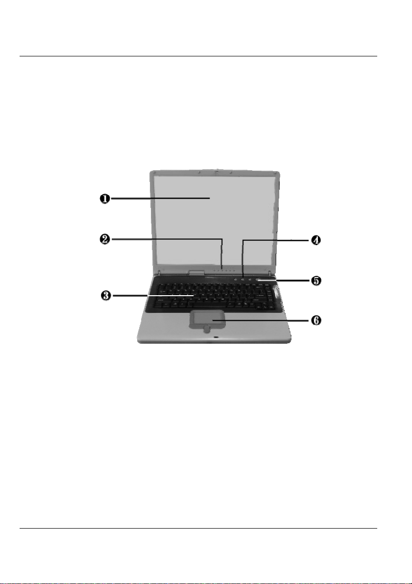
1.3 The Inside of the Notebook
The notebook computer is compact with features on every side. First, look
at the inside of the system. The following sections describe inside features.
16
1. Color LCD Display 2. Status LED Indicators
3. Keyboard 4. Easy Buttons
5. Power On/Resume Button 6. Touchpad Pointing Device
• Color LCD Display
The notebook computer comes with a color LCD that you can adjust for
a comfortable viewing position. The LCD is 15" TFT color LCD with
1024x768 XGA (Extended Graphics Array). The features of the Color
LCD Display are summarized as follows:
⇓ TFT color LCD with 15" 1024x768 XGA resolution panel.
Page 17

Introduction1
⇓ LCD display control hot-keys allows you to adjust the brightness of
the LCD.
⇓ Simultaneous display capability for LCD and external desktop
computer monitor.
• Status LED Indicator
Keeps you informed of your notebook computer’s current operating
status and power status. Description of the status icons appears in the
latter part of this section.
• Keyboard
⇓ Standard QWERTY-key layout and full-sized 88 keys keyboard
with Windows system hot-keys, embedded numeric keypad, 7 hot
keys, inverted "T" cursor arrow keys, and separate page screen
control keys.
⇓ Wide extra space below the keyboard panel for your wrist or palm
to sit-on comfortably during typing.
• Easy Buttons
There are three easy buttons used for activating wireless function and
accessing user-defined functions instantly and easily. Description of the
easy buttons appears in the latter part of this section.
• Power On/Resume Button
Switches the computer power on and off, or resumes whenever it is in
Suspend mode.
17
Page 18
Notebook User Guide
• Touchpad Pointing Device
Microsoft and IBM PS/2 mouse compatible with three select buttons as
one Scroll button and two Touchpad click buttons. These three buttons
array below the Glide pad. The middle one is located with the Scroll
button that lets you execute the scroll page function. The two click
buttons located at each side support tapping selection and dragging
functions. These buttons work like a standard computer mouse. Simply
move your fingertip over the Glide Pad to control the position of the
cursor. Use the selection buttons below the Glide Pad to select menu
items.
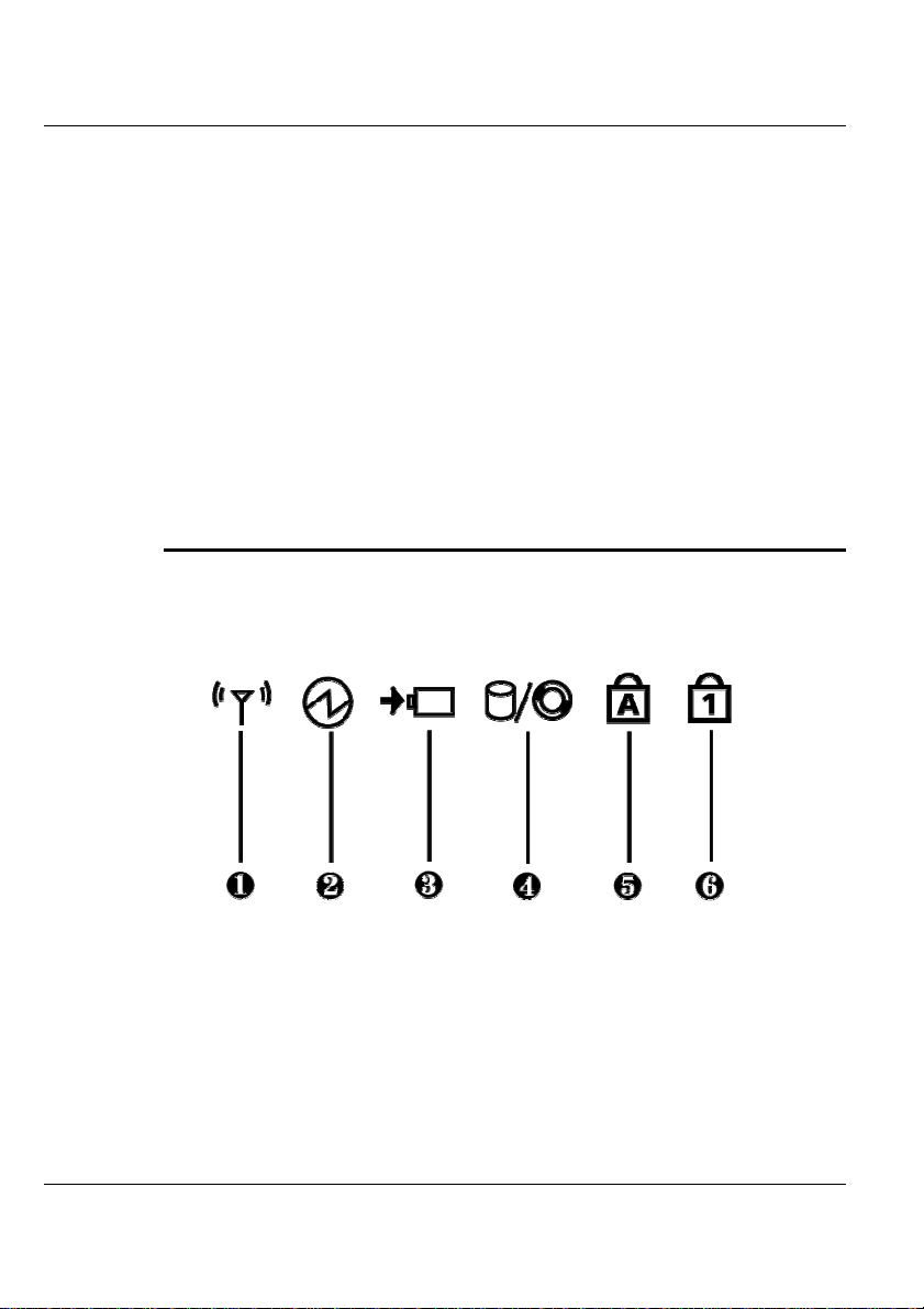
NOTEBOOK STATUS ICONS
The Status LED Panel keeps you informed of the notebook’s current
operating and power status. Each LED is marked with an icon to designate
the system status.
18
1. Wireless LAN Status 2. Power Indicator
3. Battery Charging LED 4. HDD/CD Access
5. Caps Lock 6. Num Lock
• Wireless LAN Status
When LED in green light indicates that the system is accessing data from
or is retrieving data by wireless LAN.
Page 19

Introduction1
• Power Indicator
Lets you know that power to the system is turned on. This LED is
positioned so that you can see the power state whether the LCD panel is
opened or closed.
⇓ Lights green when the system is powered on.
⇓ Lights green blinking when the system is in Suspend to RAM.
• Battery Charging LED
Lights to indicate battery in charging status.
⇓ Lights green to indicate that the battery is in charging.
⇓ Lights off to indicate the battery is fully charged or no battery
installed.
• HDD/CD Access
When LED in green light indicates that the system is accessing either the
Hard Disk or optical disk drive.
• Caps Lock
When LED in yellow light indicates that the Caps Lock key on the
keyboard is activated. When activated, all alphabet keys typed in will be
in uppercase or capital letters.
• Num Lock
When LED in yellow light indicates that the Num Lock key on the
keyboard is activated. When activated, the embedded numeric keypad
will be enabled.
19
Page 20
Notebook User Guide
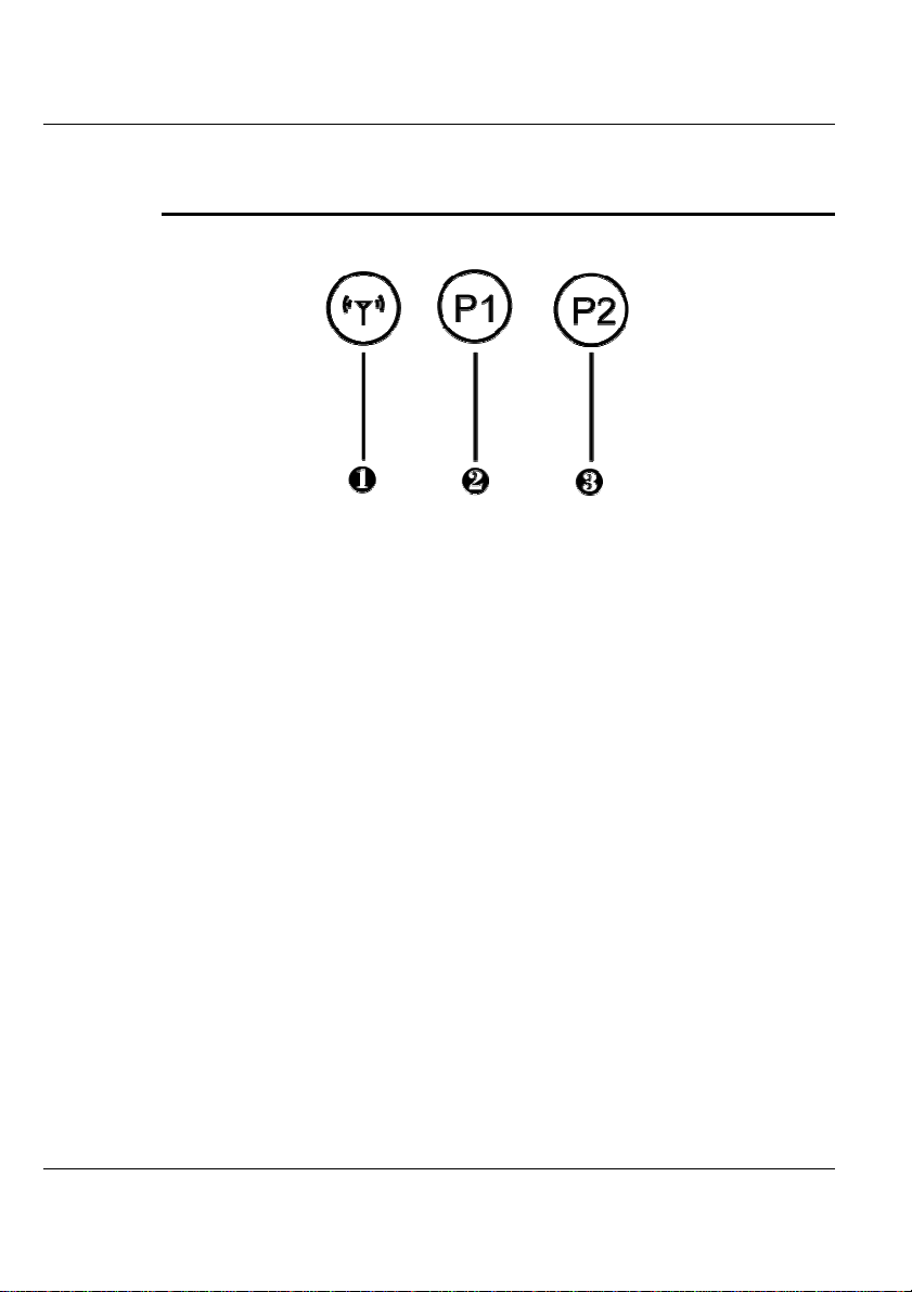
THE FUNCTION OF EASY BUTTONS
1. Wireless LAN Button 2. Easy Button 1 3. Easy Button 2
• Wireless LAN Button
Push this button to activate or deactivate the Wireless LAN. When you
activate the wireless LAN function, it will search the wireless LAN signal
automatically if you had installed the driver.
• Easy Button 1
You can define the specific function by yourself to active the program.
For example, you can define it to access the outlook 98/2000/2002...
utility just by pressing this button. You can simplify several procedures in
entering into Outlook 98/2000/2002... environment. For more details,
you can refer to Section 2.5 to recognize the driver installation
procedures in activating Easy Button 1.
• Easy Button 2
You can define the specific function by yourself to active the program.
For example, you can define it for providing a very convenient way in
connecting to the Internet only by pressing this button. For more detail,
you can refer to Section 2.5 to recognize the driver installation
procedures in activating Easy Button 2.
20
Page 21
Introduction1
1.4 The Front Side of the Notebook
1. Cover Switch 2. Battery
• Cover Switch
The cover (LCD panel) is locked when it is closed. Slide the button right
aside to release the latch for opening the cover of the computer.
• Battery
The battery provides the power for the N/B when there is no AC power
available. Please refer to chapter 2.1 on how to attach and detach the
battery.
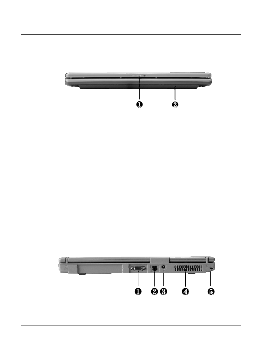
1.5 The Rear Side of the Notebook
The system ports at the back of your notebook computer can connect various
devices. Each port is described as followings.
1. VGA Port 2. Modem Port 3. DC-In Port
21
Page 22

Notebook User Guide
4. Air-Outlet Vent 5. Locking Device Keyhole
• VGA Port
Lets you attach an external CRT monitor for wider display. You can run
the LCD display and the external CRT monitor simultaneously or switch
it to CRT only using the display hot-key.
• Modem Port
A 56K internal fax/data modem is installed. It keeps you connected to
the outside world through networks.
• DC-In Power Port
Lets you connect the AC power adapter in supplying continuous power
to your notebook and recharging the battery.
• Air-Outlet Vent
Emits the heat out of your computer and keeps it within operating
temperature.
• Locking Device Keyhole
Lets you attach a Kensington security system or a compatible lock to
secure your notebook computer.
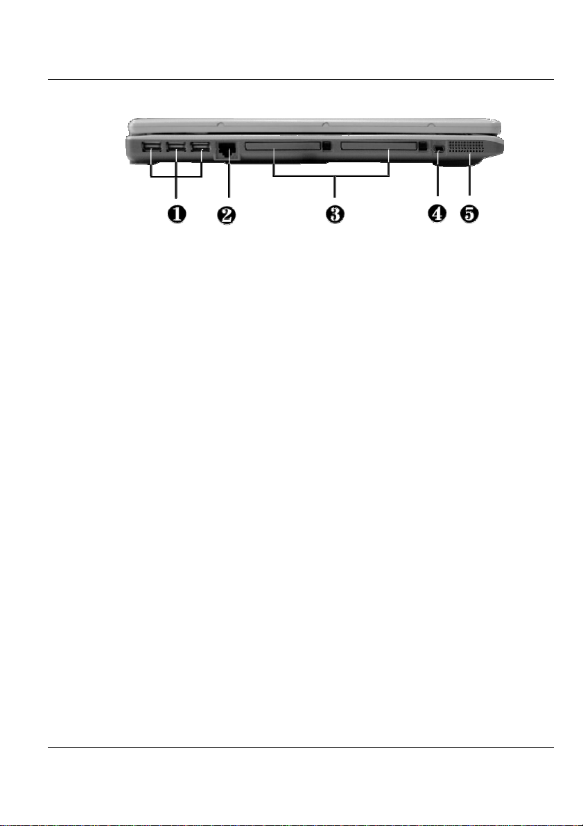
1.6 The Left Side of the Notebook
The left side of your notebook computer provides the features shown in the
following figure.
22
Page 23
Introduction1
1. USB Ports 2. LAN Port
3. PC Card Slot 4. IEEE 1394
5. Built-in Stereo Speakers
Left Side Features
• USB Port
The Universal Serial Bus (USB) port allows you to connect up to 127
USB-equipped peripheral devices (for example, printers, scanners and so
on) to your notebook computer.
• LAN Port
An internal 10Base-T/100Base-TX LAN module connects your
computer to other computers/networks through a local area network
(LAN).
• PC Card Slot
⇓ Lets you connect various PC cards such as a memory card
⇓ Supports both 3V, 5V 32-bit CardBus and 16-bit PC cards.
• IEEE 1394
IEEE 1394 port is a high speed I/O port that can transfer high levels of
data in real-time, such as external hard disk, Digital Video Camera.
23
Page 24
Notebook User Guide
• Built-in Stereo Speakers
Integrated left and right mini stereo speakers located at the two sides of
the N/B for sound and audio output for your multimedia presentations
or listening pleasure.
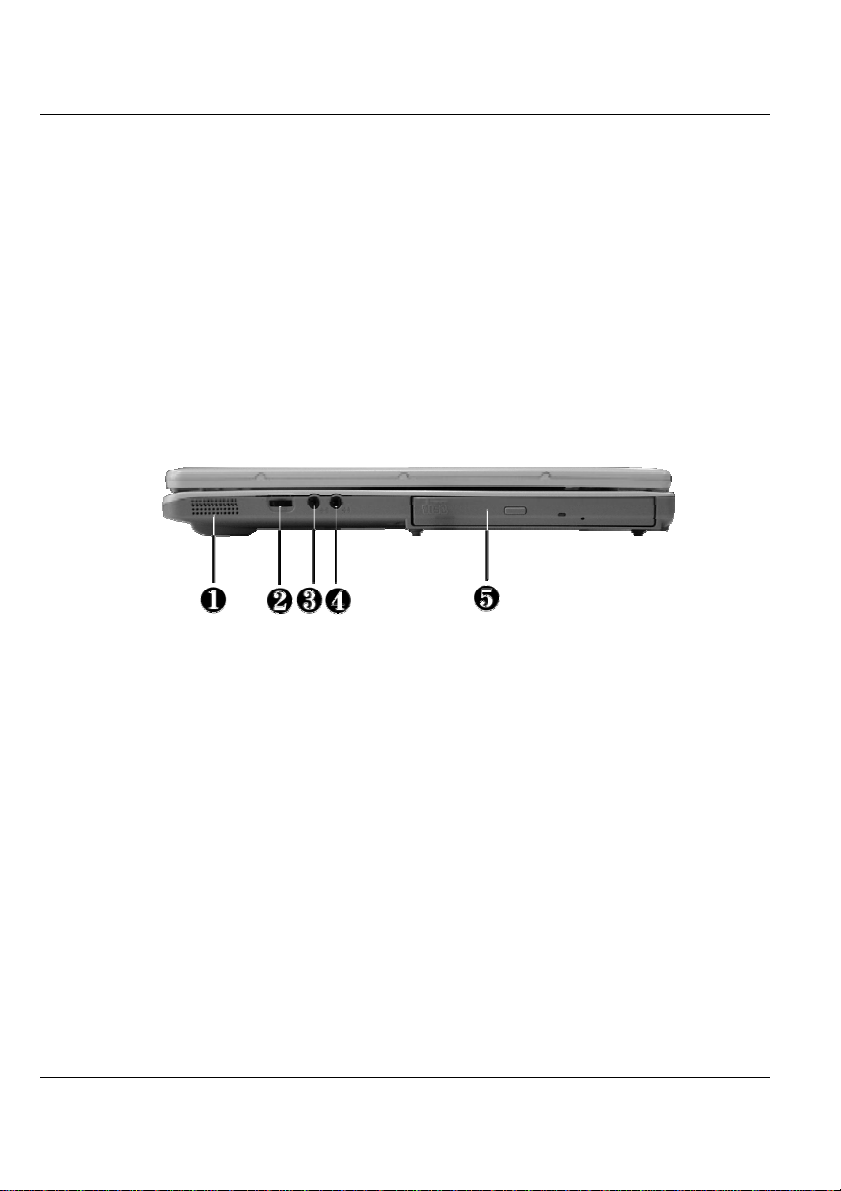
1.7 The Right Side of the Notebook
The right side of the notebook computer offers the features shown in the
following figure.
1. Built-in Stereo Speakers 2. Volume Control
3. Microphone Jack 4. Headphone Jack
5. Optical Disk Drive.
Right Side Features
24
• Built-in Stereo Speakers
Integrated left and right mini stereo speakers located at the two sides of
the N/B for sound and audio output for your multimedia presentations
or listening pleasure.
• Volume Control
Allows you to control the speaker volume.
• Microphone Jack
Allows you to connect an external microphone for monophonic sound
recording directly into your notebook computer.
Page 25
Introduction1
• Headphone Jack
Lets you plug in a stereo headphone, powered speakers, or earphone set
with 1/8 inch phono plug for personal listening.
• Optical Disk Drive
Allows you to load and start programs from a compact disc (CD) or a
digital video disc (DVD) and play conventional audio CDs. It also can
make CD’s by using a CD-R or CD-RW.
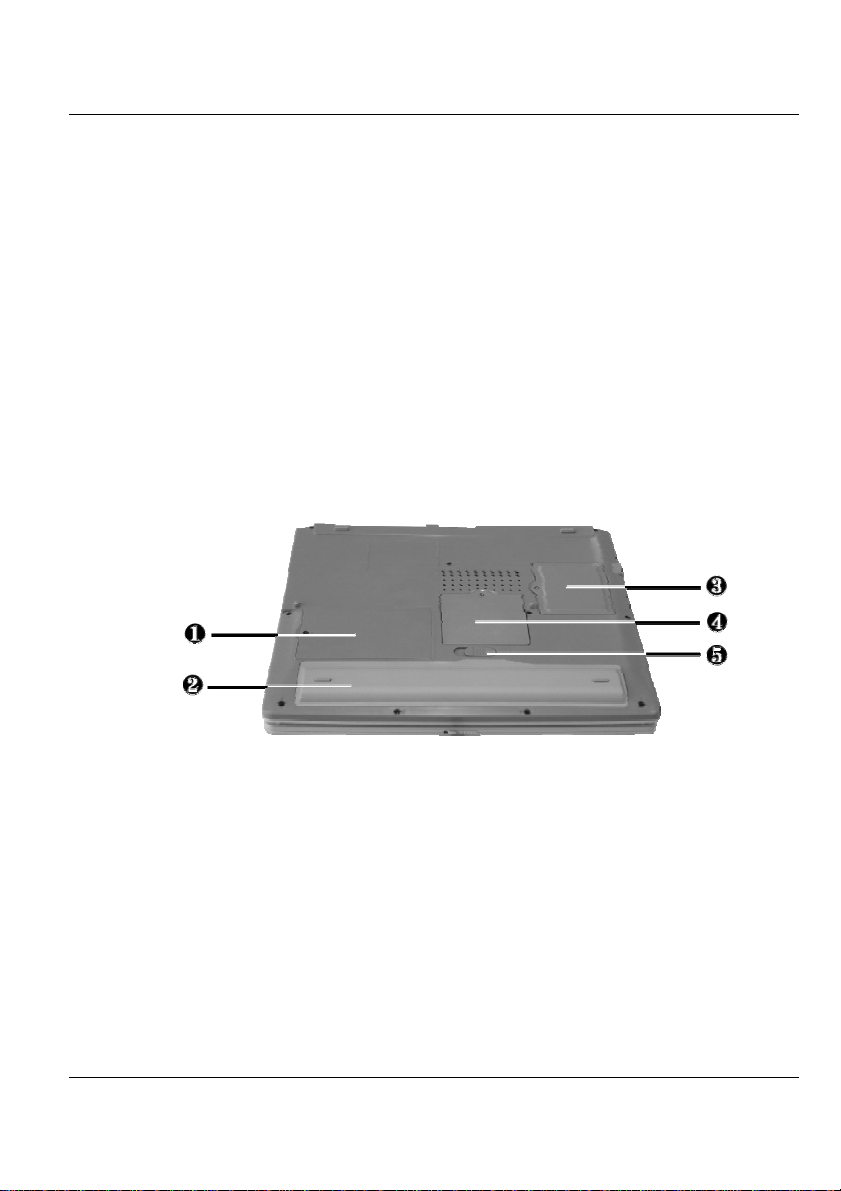
1.8 The Underside of the Notebook
The bottom of the notebook computer offers the following features.
1. Hard Disk Compartment 2. Battery Bay
3 Wireless LAN Compartment 4. Memory Compartment
5. Battery Release Latch
Bottom of the System
• Hard Disk Compartment
Open this cover to replace the Hard Disk Drive. Please refer to Chapter
7 on how to replace it.
25
Page 26

Notebook User Guide
• Battery Bay
Equipped with a Lithium-Ion (Li-Ion) battery pack.
• Wireless LAN Compartment
Provides optional wireless LAN card inserted into this compartment for
executing relative functions.
• Memory Compartment
Remove the screw to find two SO-DIMM slots.
• Battery Release Latch
Push the latch to the left to remove the battery pack.
1.9 Notebook Accessories
AC Adapter
The AC Adapter supplies external power to your notebook computer and
charges the internal battery pack simultaneously. The AC adapter has an
auto-switching design that can connect to any 100VAC ~ 240VAC power
outlets. You just change the power cord if you are going to use your notebook
in other countries with different connector outlets.
26
When you connect the AC adapter, it charges the battery whether or not the
notebook computer is powered on.
Battery Pack
Aside from the AC adapter, your computer can also be powered through the
internal battery pack. The battery pack uses rechargeable Lithium-Ion (LiIon) battery cells that provide long computing hours when fully charged and
power management enabled. You should always leave the battery inside your
Page 27

Introduction1
computer even when using the AC adapter as it also acts as a back-up power
supply in case power from the AC adapter is cut off. It is also very important
to have the battery pack always charged to prevent battery cell degradation.
27
Page 28

Page 29
2 Getting Started
Your Notebook is designed and pre-configured for
easy setup and use. This chapter describes the
installation steps you should follow to get the
notebook up and running as quickly as possible.
Contact your dealer if they have pre-installed all the
needed drivers to fully operate your computer or if
there is an update on the driver installation of the
notebook.
Getting Started 2
29
Page 30

Notebook User Guide
2.1 Using the Battery Pack
The notebook is designed to operate with one of the following power
sources:
• With AC power using the AC adapter connected to an electrical outlet.
• With a Lithium-Ion (Li-Ion) battery pack.
You should use the AC adapter whenever it is possible, relying on the battery
pack only when AC power is unavailable.
Before you use your notebook computer, install and recharge the battery pack
first. The rechargeable Li-Ion battery pack allows you to operate the
notebook without an external power source. When you connect the AC
power adapter, the battery immediately starts to recharge. Normal battery
charging time is 4 hours for Lithium-Ion (Li-Ion) battery pack when your
computer is turned off.
30
For maximum battery performance, fully discharge the battery first before
recharging it when you start to use it for the first time. To do so, unplug the
AC adapter, turn off power management features (through Setup and
Windows), and turn on the system. Once the battery is fully discharged, plug
in the AC adapter and recharge the battery.
If you do not discharge the battery completely, it fails to accept a full
recharge.
+ Li-Ion battery is vulnerable, do not charge it with other power adapter, or
it may cause fire or explosion.
Page 31

Getting Started 2
Installing the Battery Pack
This notebook provides the most convenient way to install the battery pack
into your computer. With the extended nose directed toward the
compartment, insert and push the battery pack.
Removing the Battery Pack
To remove the battery pack, slide the latch to the end of the left side to popout the battery pack, and then take out the battery pack with your finger.
31
Page 32

Notebook User Guide
Replacing the Battery Pack
When your notebook estimates that the battery only has enough charge to
continue for a few minutes, it will alert you with a battery low warning beep.
If you are consuming a lot of power by using the audio system, the PCMCIA
slots, the hard disk drives, and optical disk drive, your notebook might run
out of charge much sooner than you expect. You should always respond to
the battery low indication by connecting to AC power or turning off your
notebook, or suspending your notebook to disk. If you do not do so, the
notebook will automatically suspend to disk and turn off. The contents of the
memory will store in the hard disk drive. You will be unable to restart the
notebook until you have connected to the AC adapter or installed a charged
battery. To replace the battery pack, refer to the previous sections on
"Installing the Battery Pack" and "Removing the Battery Pack."
+ For Window 2000/XP, the suspend mode (Hibernate or Standby) can be
chosen in Power Options of Windows's Control Panel)
+ Be sure to save your data before replacing the battery pack or connecting
the AC adapter. Failure to do so can result in data loss.
32
EXTENDING BATTERY LIFE
It is important to be aware of the simple things for extending the life of the
system main battery while you are on the road. You should find a working
place where the external lighting is not too bright and turn down the screen
brightness. Also, you can choose the available mode in the Power
Management item of the Control Panel in Windows.
Page 33

Getting Started 2
2.2 Connecting the AC Power Source
The AC adapter provides external power source to your computer and
charges the internal battery pack at the same time. The AC adapter also has
an auto-switching design that can connect to any 100VAC ~ 240VAC power
outlets.
To connect the power adapter:
1. Plug the AC power cord into the power socket of the AC power adapter.
2. Plug the other end of the AC power cord to a live AC wall outlet.
3. Plug the connector of the AC adapter to the DC-IN port found at the
rear side of the computer.
+ Whenever possible, it is advisable to always have the AC adapter
connected to the notebook and the battery pack installed. This ensures
continuous power supply and prevents any data loss incurring from
sudden power breakdown.
33
Page 34

Notebook User Guide
+ Ÿ For the power supply of this equipment, an approved power cord has
to be used.
Ÿ Make sure the socket and any extension cord(s) you use can support
the total current load of all the connected devices.
Ÿ Before cleaning the computer, make sure it is disconnected from any
external power supplies (i.e. AC adapter).
2.3 Starting Your Computer
The Power/Resume button is found on the top of the base unit. Press the
Power/Resume button to start your computer and check that if the Power
LED turns on.
34
After a few seconds, the computer’s display will turn on and your computer
will begin to execute the Power On Self Test or POST to check if all system
components are running properly. Any error found during the test will be
displayed on the screen and may generate a short beep sound as well.
Page 35

Getting Started 2
After the test, the screen will also display a message "press <F2> to enter
SETUP". You don’t need to run this program at the moment as your dealer
already made the necessary settings for your computer’s optimal operation.
Refer to Chapter 6 on running the SETUP program later.
After the test has completed, your computer will start to search and boot up
the operating system from your hard drive. The notebook computer normally
comes with a Windows operating system pre-installed in your hard drive.
Consult the Windows manual on how to use the program. If not, contact
your dealer for assistance.
2.4 Adjusting the Display Controls
The LCD brightness adjustment is controlled by <Fn> +<F8> and <Fn> +
<F9> keys respectively. You need to press these hot-key controls after
powering on your notebook to suit your viewing pleasure.
The Brightness hot-key control adjusts the brightness on the LCD. The
brightness hot-key control will not set the LCD completely dark or bright; it
provides sufficient lighting to the LCD to match the external lighting of the
surrounding. The brighter the room, the more you need to increase the
brightness of the LCD.
2.5 Turning off Your Computer
If you are not going to use the computer for a while, it is best to turn off the
power of the computer for longer use. Before turning off the power, you
need to first close all application programs and shutdown the operating
system.
35
Page 36

Notebook User Guide
After turning off the computer, make it a habit to leave the LCD panel open
for a while whenever used for an extended period of time. This allows the
inside parts of the computer to cool off. Closing the panel will force the heat
up against the LCD screen, which may degrade the LCD when done regularly.
More importantly, never close the LCD panel for a long period of time when
computer is on and power saving features are disabled.
36
Page 37

Using Your Notebook 3
3 Using Your Notebook
This chapter describes how to operate the standard
features of the notebook that you normally would use in
your day-to-day computer work. If you are new to
computers and to your operating system, you also need to
read the manual for the operating system on how to work
with your computer. It is very important to familiarize
yourself well with the operating system. The succeeding
chapters not only guide you to go beyond the basics, but
also try other exciting features.
37
Page 38

Notebook User Guide
3.1 Starting Your Operating System
The operating system is a must ingredient in using your computer. Without an
operating system, it is like playing chess without the chessboard. It is the
platform for all your software application programs to run on. The most
popular operating system today is Microsoft Windows. You should have
installed one operating system by your dealer unless you are an expert
computer user and would need a more powerful operating system. If you
have an operating system already installed in your computer, then you would
be up and running after you power on your computer and boot up the
system. Check your operating system manual on how to run it.
3.2 Understanding the Keyboard
Functions
38
Your notebook computer is equipped with an 88 key keyboard that provides
all the functionality of a full-sized 101 or 102-key IBM keyboard. Aside from
the standard typewriter-layout keyboard of your computer, there are a
number of extra features and function controls on the built-in keyboard
including Windows system hot keys.
Page 39

Using Your Notebook 3
1. Function Keys 2. Control Keys
3. Windows Start Menu Key 4. Control Keys
5. Windows Shortcut Key 6. Cursor Control Keys
Keyboard
Key features and operations are described below:
• Function Keys
Function keys are application-driven, like F1 through F12 can be found
on the keyboard. These keys work together with the Fn key to activate
special functions. Some keys (printed in blue on keypad) are
preprogrammed with dual functions.
• Control keys — Ctrl, Alt, Fn, and Shift are controls used in
conjunction with other keys to change their functions. To use control
keys, press and hold the control key while pressing another key. For
example, "Press Ctrl-C" means to hold down the Ctrl key and type the
letter C. Key combinations work especially to the application you are
running.
39
Page 40

Notebook User Guide
• Windows keys
Use the following two keys to facilitate your work:
⇓ Start Menu key
Displays the Start menu.
⇓ Shortcut/Application key
Provides quick access to shortcut menus. This key acts like a right
mouse button.
• Cursor Control keys
Cursor control keys let you position the cursor on the screen where you
want. In the screen, the cursor is a blinking underline, block, or vertical
bar depending on the application. The cursor indicates where the next
text typed is inserted.
• Typewriter keys
Typewriter keys (also called alphanumeric keys) are used to enter text and
characters. Keys with blue print on them behave differently when
combined with control keys.
40
Page 41

BASIC KEYBOARD FUNCTIONS
NumLk
Ins
ert
PrtSc
SysRq
ScrLk
Del
ete
Pause
Break
Keypad Function Description
Using Your Notebook 3
Enter
<Enter> key. Execute a command. Within
many text editing application programs, the
<Enter> key inserts a hard carriage return, just
like what ordinary typewriter does.
Esc
<Esc> key. Press this key to cancel or escape
from a command or function.
<Ins> key. Known as the Insert key. Press this
key to toggle the keyboard data entry from
insert to type over mode.
Shift +<PrtSc> key. Known as the Print Screen
Shift
+
key. Press this key to map the whole screen to
share memory for your specific usage.
<Del> key. Known as the Delete key. Press this
key to delete the character to the right of the
cursor, or delete marked texts or items.
Shift +<Pause> key. Press this key to
Shift
+
temporarily halt execution of a command.
Pressing any other key to resume execution of a
command.
Backspace
<Backspace> key. Press this key to delete the
character to the left of the cursor.
Shift
<Shift> key. Press this key in combination with
alphabet letters to produce uppercase letters in
typing. Use this key in combination with those
two-character keys (found on the second row of
the keyboard) to produce the upper marked
41
Page 42

Notebook User Guide
Fn
NumLk
Ins
ert
Fn
ScrLk
Del
ete
Keypad Function Description
Tab
Ctrl
Alt
+
Caps
Lock
+
keys. Also used in most application program in
combination with other keys to execute a
certain command.
<Tab> key. Press this key to move the cursor
to the next tab stop on the right. This key works
much the same as in ordinary typewriter.
<Ctrl> key. Known as the Control key. Used in
most application program in combination with
other keys to execute a certain command.
<Alt> key. Known as the Alternate key. Used
in most application program in combination
with other keys to execute a certain command.
Fn +<Num Lock> key. Activates the
embedded 15-key numeric keypad. The keys are
color coded blue.
<Caps Lock> key. Used in most application
program to always activate uppercase alphabet
characters.
Fn +<Scroll Lock> key. Used in most
application program to scroll the screen without
having to move the cursor.
CURSOR CONTROL KEYS
Keypad Function Description
Up arrow key. Moves the cursor up one line at a
time.
42
Page 43

Keypad Function Description
Down arrow key. Moves the cursor down one
line at a time.
Left arrow key. Moves the cursor to the left one
space at a time.
Right arrow key. Moves the cursor to the right
one space at a time.
SCREEN CONTROL KEYS
Keypad Function Description
<Home> key. Moves the cursor to the
Home
PgUp
beginning of a screen or line.
<PgUp> key. Moves the cursor up one
screen at a time
Using Your Notebook 3
<PgDn> key. Moves the cursor down
PgDn
one screen at a time
<End> key. Moves the cursor to the
End
end of a screen or line.
WINDOWS HOT KEYS
43
Page 44

Notebook User Guide
Fn
Fn
Fn
Fn
Keypad Function Description
SPECIAL FUNCTION KEYS
The notebook has special system function keys that activate key serving dual
functions. When pressed in conjunction with the <Fn> key, these keys set
specific system parameters and are sometimes referred to as "hot keys".
Keypad Function Description
+
<Start> key. Pulls up the Windows Start menu.
<Right Click> key. Performs a mouse right-click
function for Windows system.
Enable or Disables the built-in system
F3
Mute
speaker.
44
Press this key to activate the system into
F4
+
Suspend
the suspend mode.
Switches display between LCD, CRT, or
F7
+
CRT
LCD and CRT simultaneously.
Increases the brightness of LCD display
F8
+
incrementally.
Page 45

Using Your Notebook 3
Fn
Keypad Function Description
Decreases the brightness of LCD display
F9
+
incrementally.
3.3 Using the Glide Pad Pointing
Device
Your computer comes with a built-in Glide Pad pointing device that is found
on the center of the palm-rest surface.
The Glide Pad offers a number of options that let you customize how it
functions. To access these options, locate the Control Panel and double
click on the Mouse icon. The options let you control the size and color of
the cursor, cursor speed, the accepted double-click speed, and selection
button orientation.
The Glide Pad works a mouse pointing device replacement that is used under
Windows-based operating system. You can use the standard Microsoft driver
that is compatible with the Glide Pad device and is normally used under
Windows-based operating system. However, if you want to utilize the added
features of the Glide Pad, you may want to try installing its own device driver
that comes with added utilities for enhancing the function of the device.
45
Page 46

Notebook User Guide
1. Left Selection Button 2. Scroll Button
3. Right Selection Button 4. Glide Pad
Glide Pad Features
46
Here how to use the Glide Pad pointing device:
1. The rectangular surface acts like a miniature duplicate of your display
screen. To move the mouse cursor, place the finger lightly on the sensor
pad and move in the desired direction. If you reach the end of the pad,
lift your finger and place it back down on the other side of the pad.
2. To select an item, click on the item by pressing the left button control or
by simply tapping on the surface once. A light, quick tap always works
best. To execute an item, click the left button twice or do a quick double
tap on the surface.
Page 47

Using Your Notebook 3
3. To simulate holding the mouse button down (dragging an icon or
selection), use the tap-and-drag gesture. This feels much like a doubleclick, except that the finger remains on the pad after the second tap: Tap,
lift, tap, hold and move. The simulated button remains held as long as
the finger remains on the pad.
4. To scroll up or down the screen, just slide up or down the scroll button
to move the screen up or down.
+ Avoid spilling any liquid on the Glide pad surface and always keep the
Glide pad surface and pointing finger dry from sweat build-up. Also do
not expose the Glide pad to any magnetic source object.
3.4 Configuring Your Screen Display
The VGA display function of your notebook is based on a high performance
AGP local bus controller and is fully IBM VGA compatible. This controller
offers a large set of extended functions and higher resolutions especially
useful when you are connecting an external high-resolution and highfrequency CRT or LCD.
Please Refer to Section 5 "Installing the Notebook Device Drivers" of
Chapter 2 in this manual for the procedures on how to install the VGA
device driver under Windows. After installing the VGA driver, you would
then configure the display resolution or screen size to match your LCD
display panel. This notebook computer model provides 1024x768 resolution.
You would also probably want to set the amount of color output to display
sharper images and photos.
47
Page 48

Notebook User Guide
POSSIBLE DISPLAY CONFIGURATIONS
The table below shows you the possible display resolution you can set when
using either the LCD display or the external monitor (CRT):
Display Possible Resolution Maximum Colors
1024x768
XGA LCD
CRT Only 640x480
640x480
800x600
1024x768
800x600
1024x768
1152 x 768
1280x1024
1400x1050
1800x1440
64k colors
64k colors
64k colors
16 million colors
16 million colors
16 million colors
16 million colors
16 million colors
16 million colors
+ 65,536 or 64K colors is also equivalent to 16-bit high color while 16 million
or 16M colors is equivalent to 32-bit true color.
+ You can use the <Fn> + <F7> hot-key to switch the display between
LCD only, CRT only, or both LCD and CRT display.
CHANGING THE DISPLAY PROPERTIES UNDER WINDOWS
To change the display properties of your screen under Windows system, just
right-click on the desktop area and select Properties or go to the Control
Panel and click on the Display icon. The Display Properties dialog box will
appear on your screen. Click on the Settings tab to set your desired
configuration. Make sure to follow the configuration table above.
48
Page 49

Using Your Notebook 3
+ If you cannot configure the display properties, change the display driver
first as mentioned on Section 5 "Installing the Notebook Device Drivers"
of Chapter 2 in this manual. Consult your dealer for the latest Windows
VGA driver.
3.5 Knowing the Power Saving
Features
One of the great features in your notebook computer aside from its superior
performance is the ability to save energy power. Your computer is designed
to incorporate intelligent and advanced power management functions that
turn off power of most components when system is idle or not in use. This
does not affect the performance of your system as it monitors the activity of
your computer and resumes power and operating speed when activity is
detected. This feature not only gives you longer battery hours but cooler
systems and components as well. For more information on how to control
the power management features of your computer, refer to Power
Management function in Control Panel of Windows.
The definitions of power management mode are depicted as follows:
Full-On Mode
No device in the system is executed in power management, the system can
respond to all applications at maximum performance.
Suspend to RAM mode
All devices are powered off except the other supporting components and
system memory where your working files are stored. You can activate this
49
Page 50

Notebook User Guide
either pressing the power button or setting the Suspend timer on the Power
Management function of the Control Panel in Windows. To resume full-on
state, press the power button.
Suspend to Disk mode
When this mode is activated, the context of the entire system is saved to disk
and all components and devices are powered off, while all clocks are also
stopped (except Real Time Clock or RTC). You can activate this by setting
the Hibernate (Windows 2000/XP) mode on the Power Management
function of the Control Panel in Windows. To resume full-on state, you can
press the power button.
Mechanical off Mode
All power, except the RTC (real time clock), has been turned off from the
system. This includes external AC power source and battery power source.
3.6 Working with the Built-in HDD
Your notebook computer is equipped with a built-in large capacity 2.5 inch
IDE hard disk drive where you store or install your computer operating
system and all application software programs. You need to format the hard
disk before using. The internal hard disk is normally assigned as Drive C after
formatting. Sometimes divided into two partitions, adding a Drive D. Since
your computer supports different hard disk capacities (up to 60 GB), you also
need to setup the disk type first on your computer’s BIOS SETUP program
before formatting the disk drive. Your computer supports Auto-detect hard
disk type, so you do not need to set it manually. Your dealer should already
have done all of this for you. You can refer to Chapter 6 on how to run the
BIOS SETUP program.
50
Page 51

Using Your Notebook 3
You can increase the system’s storage capacity by replacing the standard hard
disk drive with a drive of greater storage capacity.
+ If you wish to replace your hard disk, contact your local dealer for more
information about this dealer-installable device.
+ Always turn off your computer first before removing the hard disk drive.
Failure to do so will damage the computer and the hard disk. Avoid
jarring or moving the computer while the hard disk is still being accessed.
3.7 How to Access the Optical Disk
Drive
Your system ships with an optical disk drive installed on the right side of
your computer. You would normally use the drive for installing operating
system and software application programs.
To insert and remove a disc on the drive:
1. Make sure the computer is turned on. Press the eject button found on
the door cover of the optical disk drive. The CD tray mechanism will
pop-out slightly and slowly pull out the whole length of the tray.
2. Place the disc on top of the CD tray with the label side facing up. Gently
press the compact disc onto the center spindle to secure the disc.
51
Page 52

Notebook User Guide
3. To remove the disc, press on the center spindle and pull up the disc
from the side until the disc snaps out of the spindle lock.
+ If the eject function is disabled by software or a power failure occurs, the
Emergency Eject Hole allows you to manually remove a CD from the
reader.
4. To close the optical disk drive, simply push the CD tray inside. The
optical disk drive LED will activate when the disc is detected. Wait until
the LED has turned off and then start to read the disc.
52
How to take care of the CD
When you handle CDs, pay attention to the following guidelines:
• Always pick up the CD by its edges.
• Avoid scratching or soiling either side of the CD.
• Do not write with the hard ball-point pen or apply labels on either side
of the CD.
• Keep the CD away from direct sunlight or high temperatures.
• Clean fingerprints or dust from the CD by wiping it with a soft cloth.
The above points also apply to other optical storage media.
Page 53

+ The optical disk drive is a Class 1 Laser Product.
3.8 Using PCMCIA Cards
WHAT IS PCMCIA?
PCMCIA or Personal Computer Memory Card International Association is a
non-profit trade association that defines the industry standard for the PC
Card technology. The goal of PCMCIA is to ensure that any PC Card can
work in any mobile computer built with a PCMCIA slot.
To allow manufacturers to add functions and technologies in the PC Card
form factor, PCMCIA has defined two PC Card types:
Type Thickness Sample Devices
Type II 5.0 mm Fax/Modem & Network Cards
Type III 10.5 mm Hard Disks (ATA Cards)
Using Your Notebook 3
Type II Cards
Type II card has a thickness of 5.0 millimeters (mm). Type II cards are often
storage or communications devices such as Flash Memory, LAN, and Small
Computer System Interface (SCSI). Typical Type II cards include
input/output (I/O) features such as modems and LANs. The features for
Type II Cards include following characters:
53
Page 54

Notebook User Guide
• Type II Extended Cards
Many PC cards are Type II extended cards. The extended card has an
additional physical component that protrudes beyond the traditional
card size. The extension can be as large as 40 mm deep by 9.65 mm high.
This extension provides room for additional electronics as well as a
location for external connectors. The GPRS card is an example. The
extended part is for additional electronics and antenna.
• Communication Cards
Both network PC cards and fax/modem cards can use with your
notebook computer. However, if you use built-in LAN/Modem module
of this computer, it is not necessary to use those cards.
• Storage Cards
When you insert a storage PC card, PC card Adapter for other memory
card (i.e. Compact Flash card, Smart Media card...) or small hard drive
card in the notebook computer, it appears as a unique drive depending
on the type of card you are using.
The following table provides sample drive designations.
54
Sample Drive Designations
Drive letter Location/Device
C: Internal hard disk
D: Internal hard disk, 2nd partition
E: CD/DVD/RW/optical disk drive
F: Slot 0, high-speed memory card
Type III Cards
Type III cards are thicker (10.5 mm) than Type II cards and allow no
extensions. This notebook does not support Type III Card.
Page 55

Using Your Notebook 3
WHAT IS CARDBUS?
CardBus is the high-performance 32-bit PCI bus master interface from
PCMCIA. It runs up to 33MHz clock speed and operates at only 3.3V. Your
notebook computer incorporates the CardBus inside the PC card slot. Aside
from 3.3V CardBus PC cards, you can also insert 5V 16-bit PC cards that can
also be detected and used by your computer.
INSERTING AND REMOVING A PCMCIA CARD
Your computer includes hot swapping capability, that allows you to exchange
cards while the computer is turned on and start using it immediately.
Inserting PC Cards
To insert a PC card into the PCMCIA slot:
1. Locate the PC card slot cover on the left side of the computer.
2. Insert the side of the PC card with the 68-pin socket into the PC slot.
The face label of the card should also be facing up.
3. When the full length of the card is almost inside the slot, push firmly but
slowly, to ensure full connection with the computer. The PC card will be
detected and once the needed driver is installed, it will generate a beep
sound to indicate that the card is detected.
55
Page 56

Notebook User Guide
Removing PC Cards
To remove a PC card from the PCMCIA slot, you should first disable the
PCMCIA card setting in the system as described followings:
1. Double click the PC card icon on the right bottom side of the task bar.
2. Select the socket from the list that you want to remove, and click the
Stop button. The system then disables the function of the PCMCIA card.
56
3. Then you can remove the inserted PC card, push the button found on
the right side of the PC slot to release the eject button. Then push it
again to release the PC card.
4. When the PC card has moved out a space out of the slot, hold the edges
of the card and slowly slide it out.
Page 57

Using Your Notebook 3
MAKING PC CARDS WORK
Since PC cards come in different types and brands, making every card work
on your computer may not that be easy. PC cards like network, SCSI or
multifunction cards (MFC) need additional driver installation and
configuration in making the card work. This additional driver may already be
built-in under Windows that Windows will try to detect and prompts you if
you want to install the driver. If the driver is not included under Windows,
you will need to insert the driver CD provided by the PC card manufacturer
into the optical disk drive and install to Windows system. You need to read
the manual guide of the PC card on how to configure and operate the card.
+ Some PC cards require additional system resources. Before inserting a PC
card you may have to disable either the USB port, or the 56K internal
modem. Check the Windows device manager to ensure that there are no
conflicts of resource amount those devices.
57
Page 58

Notebook User Guide
HOT SWAPPING PC CARDS
Just like a floppy disk drive, your PCMCIA slots allow you to replace one PC
card with another even while your computer is on. However, you need to
remember the rule that if the PC card is in use, you must not remove it.
+ PC cards draw power even when not in use. To save energy, press the
button to disconnect the card when it is not in use.
58
Page 59

Fun with Multimedia 4
4 Fun with Multimedia
This chapter lets you make full use of all the
multimedia features of your computer in having fun
and excitement during work or leisure. You will
learn how to mix and match the built-in sound
system, and use the optical disk drive in creating an
exciting full multimedia presentation.
59
Page 60

Notebook User Guide
4.1 Notebook Multimedia Features
Your notebook computer is rich in multimedia features that make your
computing fun, comfortable, exciting and easy. Your computer is well able to
perform all multimedia tasks through the following:
• Intel® Pentium® M microprocessor powered by Intel® Centrino™
Mobile Technology
• Up to 1GB DDR SDRAM
• Optical disk drive for DVD/CD watching/playing and CD making
• Integrated Intel graphics engine.
• 16-bit Audio Sound System with built-in speaker and microphone.
4.2 Audio Sound System Features
60
Your computer has a built-in 16-bit stereo sound controller that allows you to
record, store, and playback voice, music and other sound effects with built-in
mixer controls. An integrated full-duplex microphone and twin mini-speakers
are also built-in into your computer to allow you to record and playback
sound anytime and anywhere.
On the right side of your computer, you will find the audio ports that include
the following:
• External 1/8-inch microphone jack that connects external microphone
for recording purpose.
• Earphone or headphone jack for personal listening.
Page 61

Fun with Multimedia 4
• External thumb-wheel volume control.
4.3 Setting Up the Audio Driver
Properties
Before you can start using the audio capabilities of your computer, you need
first to setup properly the audio driver after installing Windows. If you
bought your computer with Windows pre-installed, it is most likely that your
dealer has configured the sound driver for you. If not, you must refer to
Chapter 2 on how to setup the sound drivers for Windows.
4.4 Windows Multimedia Programs
Windows provides several multimedia programs that you can run with the
built-in features of your computer. Pointing the Start button, Programs,
Accessories, then Entertainment, you will find the Multimedia programs
group. (The section below use Window XP as examples)
61
Page 62

Notebook User Guide
Figure 4-1 Entertainment Programs Group
The standard multimedia components are as follows:
• Windows Media Player - for playing sound, video and animation files
• Sound Recorder - for recording sounds and playback
• Volume Control - for adjusting the volume of mixer
+ For more information on how to operate these multimedia components,
run the program and click on the Help menu.
4.5 Recording Sounds
Your computer allows you to record voice and other sounds in several ways
and stores them as files on your hard disk. These voice or sound files can
62
Page 63

Fun with Multimedia 4
then be played back through the internal speaker or earphone jack using an
external speaker, headphone, or earphone set. You can also use the files as
voice annotations on many applications for more real presentations. This
section will describe briefly how you can record sounds under the Windows
operating system.
To record sounds, you need to run the Sound Recorder program from the
Multimedia program groups. The control buttons of the Sound Recorder are
simple to understand which comprise of the Fast Rewind, Fast Forward,
Play, Stop, and Record buttons. Click the Help menu on how to operate the
Sound Recorder.
Figure 4-2 Sound Recorder
The Sound Recorder also allows you to record sound from different input
audio source like the following:
• From the external microphone
• From the optical disk drive
Since you could record sound from different input sources, you must first set
the proper audio input recording device under the Recording Control panel.
To do this:
63
Page 64

Notebook User Guide
1. Double-click on the Volume Control on the taskbar or click Start button,
then point to Programs, Accessories, Entertainment and then click on
Volume Control.
2. Click Properties in the Options main menu.
3. Click the round button for Recording and tick off each component that
list in the "Shows the following Volume Controls" box.
64
Figure 4-3 Audio Properties
4. Click OK and the Recording Control dialog box will appear. Here, you
will select the input device for the recording source. If you want to
record from the optical disk drive with audio music, you must click on
CD Player.
Page 65

Fun with Multimedia 4
Figure 4-4 Recording Volume Control
USING AN EXTERNAL MICROPHONE
Your computer allows you to connect an external microphone for high
quality recording. The external microphone jack is found on the right side of
your computer. Use only a microphone with 1/8-inch mini-jack connector.
Follow the same procedure for recording voice.
USING THE BUILT-IN OPTICAL DISK DRIVE
You would normally use the optical disk drive for recording audio music
from the Audio CD. Follow these steps:
1. Activate CD Player volume on the Recording Control as discussed
earlier.
2. Run the Sound Recorder program.
65
Page 66

Notebook User Guide
3. Insert the audio CD into the optical disk drive. Unless you have disabled
the CD auto-insertion notification for supporting Suspend mode, the CD
Player should automatically run after you have inserted an audio compact
disc and will start playing the audio CD.
66
Figure 4-5 Play Audio CD by Windows Media Player
4. Select the starting point where you want to start recording.
5. Switch to the Sound Recorder and press the Record button.
6. Switch immediately to the Windows Media Player and press the Play
button. You can adjust the volume control so you can also hear the
music while recording.
Page 67

Fun with Multimedia 4
4.6 Playing Audio and Sound
Your computer has built-in twin speakers to playback audio and sound. You
can also adjust the volume manually by adjusting the thumb-wheel volume
control found on the right side of your computer.
For more quality sound output, you can choose to connect an external
amplified speaker or earphone from headphone jack. Always minimize the
volume first before placing the phone set to your ear.
USING THE WINDOWS MEDIA PLAYER
The easiest way to playback multimedia media files is to run the Windows
Media Player. Follow these steps:
1. Click on Start, point to Programs, Accessories, and then
Entertainment.
2. Click on Windows Media Player to start program.
3. Click on the File menu and select the file you want to play.
4. When the file is recognized and open, click on the Play button to start
playback.
4.7 Playing Video and MPEG Files
Your computer is capable of running video motion files as well as MPEG
(Motion Picture Expert Group) files on CD, DVD, or CD-RW. By using
software MPEG program, you can watch real full-motion picture on your
computer. You can also run the Windows Media Player under the
Entertainment programs group as well to show all media device programs.
67
Page 68

Notebook User Guide
Figure 4-6 Windows Media Player
4.8 Using Rewritable Optical Disk
68
Drive Function
CD-RW drive is a device that can write digital data to CD-RW and CD-R
compact disk (CD). With this device, you can backup your own data to CD-R
or CD-RW disc for mass data storage and safe retaining. The CD-R disc can
be written several times until the CD-R is full; the CD-RW disc, furthermore,
can write and erase data repeatedly. Please refer to the related user manual
about the CD-RW software.
+ Please pay attention to the copyright of the software or data you want to
backup. Backup or distribute the software or data might be illegal
according the restriction of the law.
Page 69

Fun with Multimedia 4
69
Page 70

Page 71

Connecting to Peripherals 5
5 Connecting to Peripherals
This chapter describes how you attach peripheral
devices to your notebook. You can attach a printer
or mouse; connect an external monitor and
keyboard, or any other peripheral device. You will
learn how to use these peripheral devices with the
step-by-step instructions depicted in this chapter.
71
Page 72

Notebook User Guide
5.1 Using the USB Port
USB or Universal Serial Port is a peripheral bus standard developed by
Compaq, DEC, IBM, Intel, Microsoft, NEC and Northern Telecom. Personal
computers equipped with USB will allow computer peripherals to
automatically configure as soon as they are physically attached - without the
need to reboot or run setup. USB will also allow multiple devices to run
simultaneously on a computer, with peripherals such as floppy drive, mouse,
digital cameras, scanners, printers, CD-RW drives, modems, keyboards,
games devices and acting as additional plug-in sites, or hubs.
+ Depending on your operational requirements, you may need to disable
other ports in order to release system resource for the USB port.
5.2 Using an External Monitor Port
Your computer has a 15-pin Monitor port for supporting any external CRT or
LCD color monitor. You need a display signal cable (usually provided with
the monitor). One end of the cable must have a 15-pin connector for the
system.
To connect an external monitor:
72
Page 73

Connecting to Peripherals 5
1. Turn off your computer and make sure the monitor power switch is
turned off.
+ The notebook computer must be powered off or suspended while the
monitor is being connected. Although you can connect the external
Monitor without power off the computer and the external monitor,
however, it is harmful to both devices and it shortens the life of these
devices.
2. Connect the connector cable of the monitor to the VGA port at the back
of your computer. Secure the cable connection with the screws provided.
3. Connect the monitor power cable and plug it into a properly grounded
wall outlet.
4. Turn on the power of the monitor.
5. Turn on your computer. Both the LCD panel and the monitor screen will
show the display. Your computer is set at default to run at simultaneous
display mode.
6. If you only want to show the display on the external monitor or
projector and shut off the LCD display, you can use the <Fn> + <F3>
hot-key to switch display type between LCD and external monitor. Keep
pressing the hot-key until you get the display to external monitor only.
73
Page 74

Notebook User Guide
+ Refer to Chapter 3 regarding the possible External CRT resolutions and
how to change the display properties.
5.3 Using the IEEE 1394 Port
IEEE 1394 is a new I/O standard that is supported by Win98 (second
edition) or later Windows version. With supporting high-speed transmission
and delivering data at a guaranteed rate, you can record digital video clips and
download them directly via a super-speed IEEE 1394 port at the left of the
notebook. IEEE 1394 becomes an ideal for devices that need to transfer high
speed of data in real-time.
With built-in IEEE 1394 port, this computer enables the peripheral devices
in transmitting digital video data or data backup. To install the IEEE 1394
port driver, please refer to Win98 (second edition) or later Windows version.
The Windows system will automatically recognize it in installing a suitable
driver for it. For other versions of Windows, please visit Microsoft's web site
for more information about it.
74
Moreover, you should install the driver of peripheral device to connect with
the IEEE 1394 port, for details please refer to the manual that comes with
your peripheral device.
Page 75

Connecting to Peripherals 5
+ Please make sure that the external IEEE 1394 HDD box you purchase at
your local electronic store should provide an external power adapter.
There are different types of IEEE1394 HDD box and hard disk from
different manufacturers, the power consumption has a varied range. If
the power of the external IEEE 1394 HDD is supplied from the USB of
this notebook, it may not run properly.
5.4 Using the External Audio System
At the right side of your computer, you will find the built-in audio ports. You
can connect Microphone jacks, earphone or a powered speaker.
To connect to an audio jack:
1. Locate the audio port (Microphone, Headphone) that you want to use to
the target device.
2. Plug the jack into the port on the right side of the system.
+ If you use external speakers and experience the sound distortion or
feedback, please lower the volume. Some factors are caused by locating
the microphone too close to the speakers. Moving the external audio
away option from the unit may also help.
5.5 Using the LAN Port
This notebook comes with an internal 10Base-T/100Base-TX LAN module
that connects your computer to other computers/networks through a local
area network (LAN) and supports data transfer rates at 10Mbps and can be
up to 100Mbps. The 10Base-T standard also called Twisted Pair Ethernet is
connected with RJ-45 connectors. The 100Base-TX is based on the older
75
Page 76

Notebook User Guide
Ethernet standard. Because it is 10 times faster than Ethernet, it is often
referred to as Fast Ethernet.
The built-in LAN module provides a standard RJ-45 connector.
To connect the twisted-pair cable to your LAN port:
1. Locate the twisted-pair cable in the accessories box in notebook
shipping carton. Each end of the cable has a RJ-45 connector.
2. Connect one end of the cable into the network wall outlet or HUB.
3. Connect the other end of the cable into the computer RJ-45 LAN port.
5.6 Using the Wireless LAN
Wireless LAN is the major breakthrough in computer communication
technology. It lets user connect to the LAN environment without using any
wire to traditional RJ-45 jack. User can enjoy the wireless connection within
the range of Access Point (AP) of LAN.
Access Point (AP) is the wireless transmission and receiving device, it
generally connects to the server of a LAN environment or act as a LAN hub
with wireless connection. Access point can be set in an office environment,
airport, major railway station, etc. that depends on the construction of each
76
Page 77

Connecting to Peripherals 5
country. In most case, you probably can use it at office, please consult with
the network department of your company for more details.
This computer integrates built-in IEEE 802.11b or 802.11 a/b wireless LAN
module, with using Intel ® PRO/Wireless network solution by Intel ®
Centrino™ mobile technology. IEEE 802.11b standard supports 11 Mbps
wireless connection speed. You can connect to the wireless LAN Access
Point without insert extra wireless LAN card into the PCMCIA slot.
Wireless LAN module is similar to LAN module. You need to install software
driver before using it. Please refer to chapter 2.5 on how to install the driver.
5.7 Using the Modem Port
This notebook comes equipped with a 56K internal fax/data modem that
allows you to communicate with others via fax, email, or to connect to an
online service or bulletin board.
The built-in fax/data modem provides on standard phone connector.
To connect the analog phone cable to your modem:
1. Locate the analog phone cable in the accessories box in notebook
shipping carton. Each end of the cable has a RJ-11 connector.
2. Connect one end of the cable into a standard wall outlet.
3. Connect the other end of the cable into the computer modem port.
77
Page 78

Notebook User Guide
+ The speed of data transmission is dependent on the quality of telephone
lines. Digitally terminated lines improve the speed of data transmission.
Contact your service provider for more information.
+ The analog phone cable is an industry standard cable. Longer cables are
available at your local electronics store.
78
Page 79

Customizing Your Notebook 6
6 Customizing Your Notebook
Your computer uses the Phoenix BIOS Setup
program that allows you to set several system
configuration in changing the way your computer
performs. This includes your system time and date,
disk drive configuration and password setup. This
information is then stored in the CMOS RAM and
will remain permanent unless you change it again.
This chapter discusses on how you will activate the
BIOS Setup program and change the system
configuration to suit your desired operation. You
must be careful to set the configuration properly in
order for your computer to run smoothly. If you are
not sure of any settings, contact your dealer.
79
Page 80

Notebook User Guide
6.1 Running the BIOS Setup Program
Your computer is likely to have been properly setup and configured by your
dealer prior to delivery. However, you may find it necessary to use the
computer’s BIOS (Basic Input-Output System) Setup program to change
system configuration information, such as the current date and time, or your
hard disk drive type. The Setup program can be accessed when you power on
the system and pressing the <F2> function key.
The settings that you specify within the Setup program are recorded in a
special area memory called the CMOS RAM. This memory is backed up by a
battery so that is will not be erased when you turn off or reset the system.
Whenever you turn on the computer, the system will read the settings stored
in the CMOS RAM and compare them to the equipment check conducted
during the Power On Self Test (POST). If an error occurs, an error message
will be displayed on the screen, and you will then be prompted to run the
Setup Program.
80
As the POST (Power-On Self Test) executes during the boot up process, the
screen will display the following message:
Press <F2> to Enter SETUP
Press the <F2> key to run the BIOS Setup program. The BIOS Setup
program is organized into five menus which you can select using the <-- and
--> keys. To move from one option to another, you use the up and down
arrow keys while using the <F5> and <F6>, or <+>and <-> keys to
change the settings. On the right hand side of the screen are some brief help
descriptions of each item you want to change.
On the BIOS Setup program, you will find the following parts on the screen:
Page 81

Customizing Your Notebook 6
• Item Specific Help
The right side of the screen. This area describes each parameter and its
available settings.
• Menu Bar
The top line of the screen. Each of the five selections displays its own
screen.
• Parameters
The left side of the screen. This area lists the parameters and their
current settings.
• Key Status Bar
The bottom part of the screen. These lines display the keys available to
move the cursor, select a particular function and so forth.
To exit the BIOS Setup program, simply press the <Esc> key and select from
the Exit menu whether you want to Save changes and exit; Discard Changes
and exit.
81
Page 82

Notebook User Guide
6.2 Using the Main Menu Setup
Phoenix BIOS Setup Utility
Main Advanced Security Boot Exit
Item Specific Help
System Time: [12 :00 :00] <Tab>, <Shift-Tab>,
System Date: [02/19/2003] or <Enter> selects
LAN MAC Address 00-40-CA-C3-9A-07 field.
Boot Display Device: [Both]
Primary Master [30006MB]
4
Secondary Master Installed CD/DVD
System Memory: 640 KB
Extended Memory: 112640 KB
CPU Type: Intel Pentium-M Processor
CPU Speed: 1300 MHz
BIOS Version: A.1A-2973-0812
F1 Help á â Select Item -/+ Change Values F9 Setup Defaults
Esc Exit ß --> Select Menu Enter
Select 4Sub-Menu
F10 Save and Exit
82
Page 83

Customizing Your Notebook 6
• System Time
Allows you to change the system time using the hour:minute:second
format of the computer.
Enter the current time for reach field and use the <Tab>,
<Shift>+<Tab>, or <Enter> key to move from one field or back to
another.
You can also change the system time from your operating system.
• System Date
Allows you to set the system date using the month/date/year format.
Enter the current time for reach field and use the <Tab>,
<Shift>+<Tab>, or <Enter> key to move from one field or back to
another.
You can also change the system time from your operating system.
• LAN MAC Address
This field reports the MAC address of the LAN module on your
notebook.
• Boot Display Device
Lets you select the display device.
• Primary Master
This field display various parameters for the hard disk drive. If type
[Auto] is selected, the system automatically sets these parameters. If type
[User] is selected, Cylinders, Heads and Sectors and other value can be
edited.
• Secondary Master
This field is for information only as the BIOS automatically detects the
optical drive.
83
Page 84

Notebook User Guide
• System Memory
This field reports the amount of base (or conventional) memory found
by the BIOS during Power-On Self-Test (POST).
• Extended Memory
This field reports the amount of extended memory found by the BIOS
during Power-On Self-Test (POST).
• CPU Type
This field reports the CPU type information detected by the BIOS during
Power-On Self-Test (POST).
• CPU Speed
This field reports the CPU speed information detected by the BIOS
during Power-On Self-Test (POST).
• BIOS Version
This field is for information only as the BIOS displays the BIOS version
during the Power-On Self-Test (POST).
84
Page 85

Customizing Your Notebook 6
6.2.1 INTERNAL HDD SUB-MENU
Phoenix BIOS Setup Utility
Main Advanced Security Boot Exit
Primary Master: [30006MB] Item Specific Help
Type: [Auto] Select the drive type
LBA Format corresponding to the
Total Sectors: [58605120] fixed disk installed
Maximum Capacity: 30006MB in your system.
If type USER is
Multi-Sector Transfers: [16 Sectors] selected, Cylinders,
LBA Mode Control: [Enabled] Heads & Sectors are
32 Bit I/O: [Disabled] Edited directly.
Transfer Mode: [FPIO 4/DMA 2]
Ultra DMA Mode: [Mode 5]
F1 Help á â Select Item -/+ Change Values F9 Setup Defaults
Esc Exit ß--> Select Menu Enter
Select 4Sub-
Menu
F10 Save and Exit
Use the Type field to select the drive type installed. You can select different
drive types as CD-ROM, User, Auto or None by pressing <Space> bar. Set
this option to Auto so your computer will automatically detect the drive type
during power on. Set this option to None when your computer is not
installed any devices. Press <Esc> to return to the Main Menu.
85
Page 86

Notebook User Guide
6.3 Using the Advanced CMOS Setup
Phoenix BIOS Setup Utility
Main Advanced Security Boot Exit
Item Specific Help
NumLock [LockOn] Selects Power-on state
for NumLock
Embedded Share Memory [32MB]
Quiet Boot [Enabled]
Screen Expansion [Enabled]
Legacy USB Support [Enabled]
USB 2.0 [Enabled]
PXE OPROM [Disabled]
Wake on LAN from S5: [Enabled]
I/O Device Configuration
4
F1 Help á â Select Item -/+ Change Values F9 Setup Defaults
Esc Exit ß--> Select Menu Enter
Select 4Sub-Menu
F10 Save and Exit
• Num-Lock
Lets you specify Enabled or Disabled for activating or inactivating NumLock function when system is booting.
• Embedded Share Memory
Lets you specify the sharing memory size of the Video chip from DDR
SDRAM. The Default sharing size is 32MB. You should carefully specify
the value, since while the set value is too high, the memory size of your
software application will be reduced.
86
Page 87

Customizing Your Notebook 6
• Quiet Boot
Lets you specify the boot screen to Logo screen or POST screen by
choosing Disabled or Enabled, respectively.
• Screen Expansion
Lets you choose full-size screen or reduced size screen for viewing the
display mode.
• Legacy USB Support
Lets you specify Enabled or Disabled for activating or inactivating
Legacy USB Device function when system is booting.
• USB 2.0
Lets you specify Enabled or Disabled for activating or inactivating USB
2.0 Device function when system is booting.
• PXE OPROM
Lets you specify Enabled or Disabled for activating or inactivating PXE
OPROM Device function when system is booting. Please set it to default
value
• Wake on LAN from S5
Lets you activate or inactivate the LAN function when system is booting
by specifying Enabled or Disabled option. Wake on LAN is a function
that you can boot the system from LAN remotely.
87
Page 88

Notebook User Guide
6.4 Security Menu Setup
Phoenix BIOS Setup Utility
Main Advanced Security Boot Exit
Item Specific Help
Supervisor Password Is Clear
88
Supervisor Password
Page 89

Customizing Your Notebook 6
Set Supervisor Password [Enter]
Set User Password [Enter]
Password on boot [Disabled]
I/O Security
Modem: [Enabled]
LAN: [Enabled]
1394/CARDBUS: [Enabled]
USB: [Enabled]
Wireless LAN: [Enabled]
F1 Help á â Select Item -/+ Change Values F9 Setup Defaults
Esc Exit ß--> Select Menu Enter
Select 4Sub-Menu
setup utility.
F10 Save and Exit
• Supervisor Password Is
This field will show Set or Clear that means whether this notebook is
controlled by Supervisor Password or not.
• User Password Is
This field will show Set or Clear that means whether this notebook is
controlled by User Password or not.
89
Page 90

Notebook User Guide
• Set Supervisor Password
Supervisor password gives you the authority in accessing the setup
utility. You also need to enter this password in system booting and
resuming from suspend mode. When you press <Enter> in this field,
the Set Supervisor Password dialog box appears. Enter a new password
with up to 8 alpha-numeric characters, and then re-enter it for
confirmation.
• Set User Password
This field is only available when Supervisor Password has set. Enter the
user password when boot the system or resume from suspend mode.
But if the Write Protect is set in the Fixed disk boot sector field, you
should enter a supervisor password to access the fixed disk when boot
the system or resume from suspend mode.
• Password on Boot
If you set this field to Enabled, your computer will ask for the password
each time you boot your computer.
90
• Modem
Lets you specify Enabled or Disabled for activating or inactivating
Modem Device function when system is booting.
• LAN
Lets you specify Enabled or Disabled for activating or inactivating LAN
Device function when system is booting.
• 1394/CARDBUS
Lets you specify Enabled or Disabled for activating or inactivating
1394/CARDBUS Device function when system is booting.
Page 91

Customizing Your Notebook 6
• USB
Lets you specify Enabled or Disabled for activating or inactivating USB
Device function when system is booting.
• Wireless LAN
Lets you specify Enabled or Disabled for activating or inactivating
Wireless LAN Device function when system is booting.
91
Page 92

Notebook User Guide
6.5 Using the Boot Setup
This item allows you to set the search drive sequence where the system will
try to boot up first.
Phoenix BIOS Setup Utility
Main Advanced Security Boot Exit
Item Specific Help
F12 Multi Boot Menu: [Enabled] Keys used to view or
configure devices:
PXE Boot with WOL: [Disabled] <Enter> expands or
collapses devices with
Boot Sequence: a + or CD-ROM Drive <Ctrl+Enter> expands
Removable Devices all
+Hard Drive <Shift + 1> enables or
disables a device.
<+> and <-> moves the
device up or down.
F1 Help á â Select Item -/+ Change Values F9 Setup Defaults
Esc Exit ß --> Select Menu Enter
Select 4Sub-Menu
F10 Save and Exit
92
Page 93

Customizing Your Notebook 6
Exit System Setup
• F12 Multi Boot Menu
Lets you specify Enabled or Disabled for activating or inactivating the
Multi Boot function by pressing F12 function key when system is
booting.
• PXE Boot with WOL
This field is for information only as whether the BIOS can automatically
detect the PXE Boot with WOL status or not.
• Boot Sequence
To select the boot device, you can use the up or down arrow key, then
press <+> to move up the device in the list or press <-> to move down
the device in the list.
6.6 How to Exit the Setup Program
There are two choices to escape from the Setup program.
Phoenix BIOS Setup Utility
Main Advanced Security Boot Exit
Item Specific Help
Exit Saving Changes
Exit Discarding Changes
Load Setup Defaults
Discard Changes
Save Changes
F1 Help á â Select Item F5/F6 Change Values F9 Setup Defaults
Esc Exit ß -- Select Menu Enter Execute Command F10 Save and Exit
and save your
changes to CMOS.
93
Page 94

Notebook User Guide
>
• Exit Saving Changes
Saves all changes to CMOS while running the BIOS setup program and
exit from the system setup program.
• Exit Discarding Changes
Allows you to discard all changes made while running the BIOS setup
program and exit from the system setup program.
• Load Setup Defaults
Lets you load the default values for all setup items.
• Discard Changes
Reverts to previously selected settings.
• Save Changes
Saves Setup data to CMOS.
94
Page 95

7 Using Options
This chapter describes the most advanced
features and expandable architecture in your
notebook. You can upgrade your memory size to
your system for specific requirements.
Using Options 7
95
Page 96

Notebook User Guide
7.1 System Upgrade
This section provides some steps in doing system upgrade for your notebook
computer. The upgrade procedures include the following:
MEMORY UPGRADE
Your notebook computer offers 200-pin SO-DIMM (Small Outline Dual
Inline Memory Module) at least 128MB DDR-SDRAM. The memory
compartment is located on the bottom of your computer. The table below
lists the possible combinations of different memory module and memory
size.
+ Please contact dealer for changing or adding DDR-SDRAM module. It is
not available for users to change it by themselves.
96
Based Memory Installing Memory Total
128 MB 0 MB 128 MB
128 MB 128 MB 256 MB
128 MB 256 MB 384 MB
128 MB 512 MB 640 MB
256 MB 0 MB 256 MB
256 MB 128 MB 384 MB
256 MB 256 MB 512 MB
256 MB 512 MB 768 MB
512 MB 0 MB 512 MB
Page 97

Using Options 7
Based Memory Installing Memory Total
512 MB 128 MB 640 MB
512 MB 256 MB 768 MB
512 MB 512 MB 1024 MB
INSTALLING MEMORY MODULE
Your computer comes with standard 128MB, 256MB or 512MB of
synchronous DDR SDRAM . You can increase system memory to a
maximum of 1024 MB in the system, by installing one small outline double
inline memory modules (SO-DIMMs) with installed base memory in the
system.
To install the memory module:
1. Make sure the system is powered off, the battery also is removed and
that no peripheral devices are attached.
2. Turn the computer upside-down and locate the screw that secures the
SO-DIMM door at the underside of the notebook.
3. Remove the screw and open the SO-DIMM cover by your finger.
97
Page 98

Notebook User Guide
4. Locate the memory module into the empty memory module sockets.
(Your system comes with one memory module already installed in the
socket.)
+ Avoid touching the exposed components inside the system. Doing so
may damage the system.
5. Insert the connector of the memory module into the socket. Make sure
the notch of the memory module fits the nose of the socket.
Ÿ Hold the memory module at a 30-degree angle and push its
connector into the memory socket of the notebook.
Ÿ Press down on the edge of the memory module until the locking
tabs on both sides is locked.
6. Put the SO-DIMM door back and secure the screw on the SO-DIMM
door.
7. Turn the system over.
To remove a memory module, push the locking tabs aside from the memory
module until the module pops up. Then, remove the memory module.
7.2 Hard Disk Upgrade
This section provides the steps in upgrading the hard disk for your notebook
computer. The upgrading procedures include the following:
UPGRADE HARD DISK
Your notebook computer offers one 2.5" format, 9.5mm height hard disk. If
the volume does not fit your need or it is crashed, you can upgrade it by
replacing with new hard disk. Please do the following steps to change it.
98
Page 99

Using Options 7
1. Remove the screws and open the cover by lifting its upper side cover.
2. Take out the hard disk from the compartment by finger carefully
3. Remove the crane screws located at each side of the hard disk.
4. Remove the connector from the hard disk gently.
5. Attach the connector to the new hard disk precisely.
6. Rotate and tighten the crane screws to the new hard disk.
7. Place the hard disk back to the compartment and push the hard disk
forward into the connector side of the computer until the hard disk is
attached to the computer.
8. Cover the lid, then rotate and tighten the screws.
9. Set the boot device as optical disk drive and Primary Master as Auto on
BIOS setup menu. Please refer to Chapter 6 about the setting of BIOS
setup menu. Then, boot the system by using WinXP CD-ROM and the
system will detect the hard disk automatically and prompt you how to
format the new disk.
99
Page 100

Notebook User Guide
+ Please tighten the screws located at each side of the hard disk before
operating the hard disk. Any vibration may cause damage for the running
hard disk.
+ Please contact dealer or certified technician for changing the hard disk
drive. Any damage that caused by inappropriately adding or changing
this HDD will not be under warranty
7.3 Wireless Module Installation
This computer uses Intel ® PRO/Wireless 802.11b or 802.11 a/b wireless
LAN module for wireless connection.
+ Please contact dealer for adding or changing this module. Any damage
that caused by inappropriately adding or changing this module will not
be under warranty
100
 Loading...