

Page 1
AVerVision VP-1HD
User Manual
Page 2

Page 3

FCC NOTICE (Class A)
This device complies with Part 15 of the FCC Rules. Operation is subject to the following two conditions: (1) this device may not
cause harmful interference, and (2) this device must accept any interference received, including interference that may cause
undesired operation.
Federal Communications Commission Statement
NOTE- This equipment has been tested and found to comply with the limits for a Class A digital device, pursuant to Part 15 of the FCC Rules.
These limits are designed to provide reasonable protection against harmful interference in a residential installation. This equipment generates
uses and can radiate radio frequency energy and, if not installed and used in accordance with the instructions, may cause harmful interference to
radio communications. However, there is no guarantee that interference will not occur in a particular installation. If this equipment does cause
harmful interference to radio or television reception, which can be determined by tuning the equipment off and on, the user is encouraged to try to
correct the interference by one or more of the following measures:
Reorient or relocate the receiving antenna.
Increase the separation between the equipment and receiver.
Connect the equipment into an outlet on a circuit different from that to which the receiver is connected.
Consult the dealer or an experienced radio/television technician for help.
Class A ITE:
Class A ITE is a category of all other ITE which satisfies the class A ITE limits but not the class B ITE limits. Such equipment should not be
restricted in its sale but the following warning shall be included in the instructions for use:
Warning - This is a class A product. In a domestic environment this product may cause radio interference in which case the user may be required
to take adequate measures.
CE Class A (EMC)
This product is herewith confirmed to comply with the requirements set out in the Council Directives on the Approximation of the
laws of the Member States relating to Electromagnetic Compatibility Directive 2004/108/EC.
Warning - This is a Class A product. In a domestic environment this product may cause radio interference in which case the user
may be required to take adequate measures to correct this interference.
Page 4

DISCLAIMER
No warranty or representation, either expressed or implied, is made with respect to the contents of this documentation, its quality, performance,
merchantability, or fitness for a particular purpose. Information presented in this documentation has been carefully checked for reliability; however,
no responsibility is assumed for inaccuracies. The information contained in this documentation is subject to change without notice.
In no event will AVer be liable for direct, indirect, special, incidental, or consequential damages arising out of the use or inability to use this
product or documentation, even if advised of the possibility of such damages.
TRADEMARKS
“AVer” is a trademark owned by AVer Information Inc. Other trademarks used herein for description purpose only belong to each of their
companies.
COPYRIGHT
©2014 AVer Information Inc. All rights reserved.
All rights of this object belong to AVer Information Inc. Reproduced or transmitted in any form or by any means without the prior written permission
of AVer Information Inc. is prohibited. All information or specifications are subject to change without prior notice.
THE MARK OF CROSSED-OUT WHEELED BIN INDICATES THAT THIS PRODUCT MUST NOT BE DISPOSED OF WITH YOUR
OTHER HOUSEHOLD WASTE. INSTEAD, YOU NEED TO DISPOSE OF THE WASTE EQUIPMENT BY HANDING IT OVER TO A
DESIGNATED COLLECTION POINT FOR THE RECYCLING OF WASTE ELECTRICAL AND ELECTRONIC EQUIPMENT. FOR
MORE INFORMATION ABOUT WHERE TO DROP OFF YOUR WASTE EQUIPMENT FOR RECYCLING, PLEASE CONTACT
YOUR HOUSEHOLD WASTE DISPOSAL SERVICE OR THE SHOP WHERE YOU PURCHASED THE PRODUCT.
Page 5

TTaabbllee ooff CCoonntteennttss
Introduction ........................................................................................................................................................................................ 1
Package Contents .............................................................................................................................................................................. 1
Optional Accessories ........................................................................................................................................................................ 1
AVerVision VP-1HD Parts .................................................................................................................................................................. 2
Technical Specifications ................................................................................................................................................................... 3
Making the Connections .................................................................................................................................................................... 4
Connecting the Power Adapter .................................................................................................................................................... 5
Connect to a Monitor with HDMI Interface ................................................................................................................................... 5
Connecting a RGB, Mac Display Monitor or LCD/DLP Projector ................................................................................................. 6
Connecting a PC or Macintosh Computer ................................................................................................................................... 6
Connect to a Computer via USB .................................................................................................................................................. 7
Connecting to a Microscope ........................................................................................................................................................ 8
Setting Up AVerVision VP-1HD ....................................................................................................................................................... 10
Unfolding the Unit ...................................................................................................................................................................... 10
Operating Height & Angle ........................................................................................................................................................... 11
Paper Guide ............................................................................................................................................................................... 11
External Memory Storage .......................................................................................................................................................... 12
Touch Button Control Panel ............................................................................................................................................................ 13
Control Panel Light Color ................................................................................................................................................................ 14
Page 6

OSD Menu ......................................................................................................................................................................................... 15
Navigate the Menu and Submenu ............................................................................................................................................. 16
Image ........................................................................................................................................................................................ 17
Presentation .............................................................................................................................................................................. 19
Setting ....................................................................................................................................................................................... 22
System ...................................................................................................................................................................................... 26
Transfer Captured Images/Videos to a computer.......................................................................................................................... 29
Troubleshooting ............................................................................................................................................................................... 30
Limited Warranty .............................................................................................................................................................................. 31
Page 7
IInnttrroodduuccttiioonn
Thank you for purchasing
the AVerVision VP-1HD.
This document camera
displays documents,
transparencies and 3D
objects onto a TV, LCD or
DLP projector making
presentations a snap.
AVerVision VP-1HD is an
ideal presentation tool for
business, academic,
medical and the scientific
community.
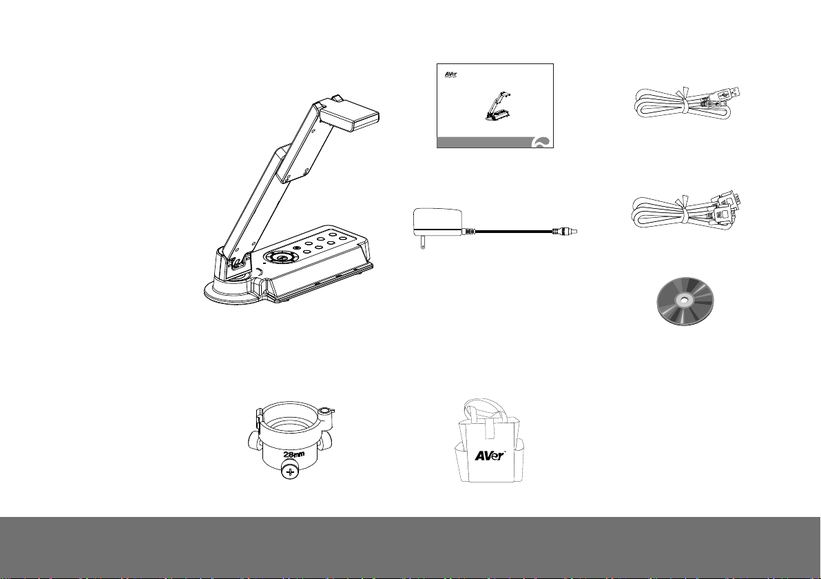
PPaacckkaaggee CCoonntteenntts
AVerVision VP-1HD
s
OOppttiioonnaall AAcccceessssoorriiees
28mm Microscope Adapter
* The power adapter will vary
depending on the country where it is
AVerVision VP-1HD
User Manual
User Manual
Power Adapter
sold
s
Bag
USB Cable
RGB Cable (VGA Cable)
Software CD
1
Page 8
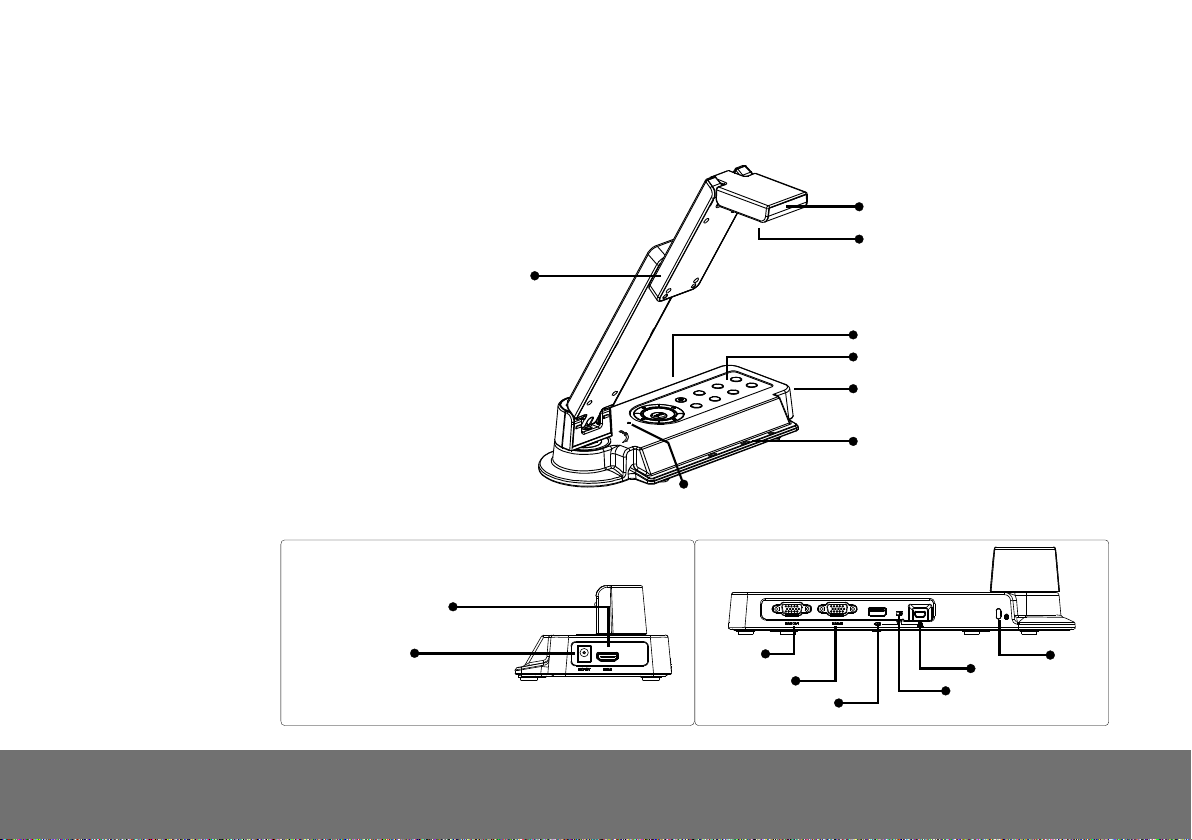
(1) Camera head
(2) Camera lens
(3) Rear panel
(4) Control panel
(5) Right panel
(6) Paper guide
(7) Bulit-in MIC
(8) Arm
(9) HDMI port
(10) DC 12V port
(11) RGB output port
(12) RGB input port
(13) USB OTG port
(14) OTG-USB switch
(15) Mini USB port
(16) Antitheft slot
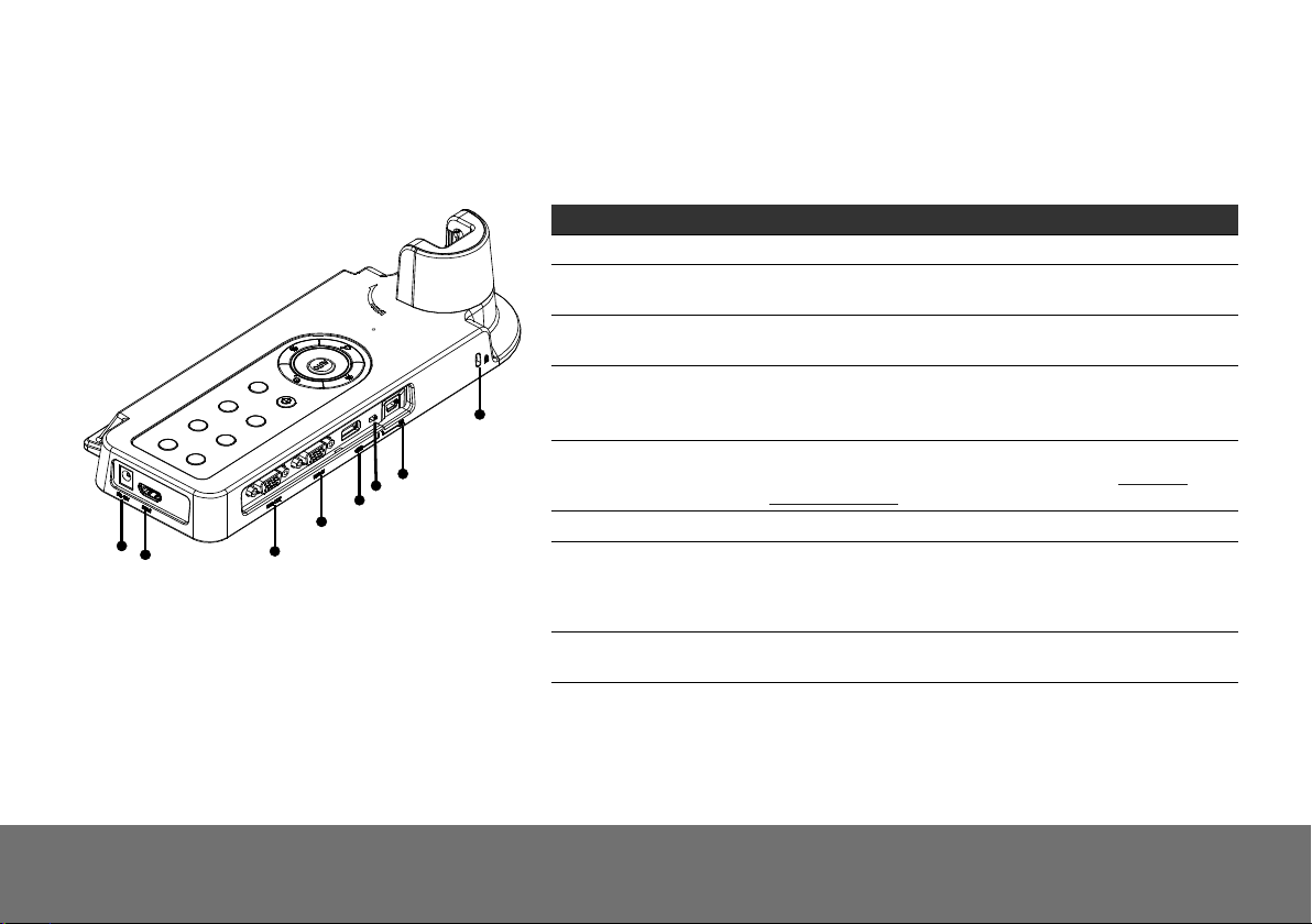
AAVVeerrVViissiioonn VVPP--11HHDD PPaarrttss
The illustrations below identify the parts of AVerVision VP-1HD.
(8)
Right Panel
(7)
Rear Panel
(9)
(10)
(11)
(12)
(13)
(1)
(2)
(3)
(4)
(5)
(6)
(15)
(14)
(16)
2
Page 9
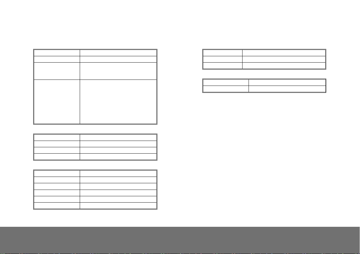
TTeecchhnniiccaall SSppeecciiffiiccaattiioonnss
Image
Sensor 1/4" CMOS color image sensor
Total Pixels 5 Mega Pixels
Frame Rate
Analog RGB output
Optics
Lens F 2.8; fl=3.38mm
Focusing Auto
Zooming Digital Zoom: 16X
Shooting Area 340mm x 255mm
Input/Output
RGB Input 15-Pins D-sub (VGA)
RGB Output 15-Pins D-sub (VGA)
OTG port USB Type A
Mini USB 1394 interface
HDMI port HDMI
DC 12V Input Power Jack
30 fps (max.)
15fps (1080p)
30fps (720p)
1920x1080,
1366x768
(VESA)(Panasonic_Japan),
1280x720,
1280x1024,
1280x800,
1600x1200,
1024x768
Dimension
Operating 275mm(L) x 114mm(W) x 335mm(H)
Folded 275mm(L) x 114mm(W) x 70mm(H)
Weight 1.2 kg (about 2.64 lb)
Power
Power Source 100-240V, 50-60Hz
Consumption 7.8 Watts
3
Page 10
(7)
(8)
Port Description
(1) DC 12V Connect the power adapter into this port.
(2) HDMI Port Output the video signal from the camera on an LCD
(3) RGB OUT Output the signal from the camera, or RGB IN port on a
(4) RGB IN Input the signal from a computer or other sources and pass
(5) OTG Port To connect external USB flash drive for data storage (ex:
(6) OTG-USB Switch Switch function from OTG port to mini USB port.
(7) Mini USB Port Connect to a mini USB port of a computer with a USB
(8) Antitheft Slot Attach a Kensington compatible security lock or antitheft
monitor with HDMI interface using HDMI cable.
VGA/Mac monitor or LCD/DLP projector.
it through to the RGB OUT port only.
Connect this port to the VGA output port of the computer.
record video, capture image…etc.)(Also see External
Memory Storage section).
cable and use AVerVision VP-1HD as a USB Camera or
transfer the captured images/videos either from the
memory source to computer.
device.
MMaakkiinngg tthhee CCoonnnneeccttiioonnss
The ports on the rear and right panel of VP-1HD enable you to connect the unit to a computer; graphics display monitor or LCD/DLP projector, TV or
other device. Illustrated below are the ports and switches that are located at the rear, and right panel of VP-1HD with their corresponding labels.
(6)
(5)
(4)
(1)
(2)
(3)
4
Page 11
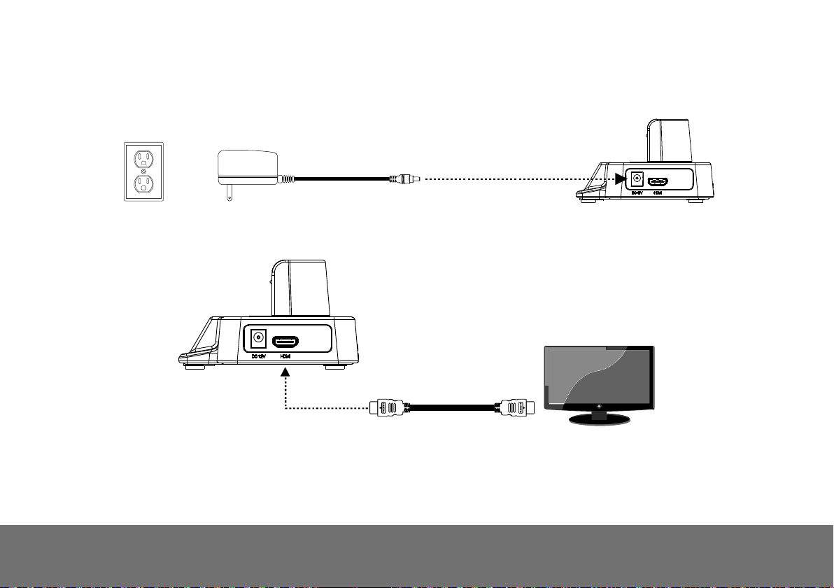
CCoonnnneeccttiinngg tthhee PPoowweerr AAddaapptteerr
Connect the power adapter to a standard 100V~240V AC power source.
Wall outlet
Power adapter
CCoonnnneecctt ttoo aa MMoonniittoorr wwiitthh HHDDMMII IInntteerrffaaccee
Locate the HDMI input port of the display device and connect it to HDMI port of AVerVision VP-1HD.
HDMI cable
HDMI monitor
5
Page 12

CCoonnnneeccttiinngg aa RRGGBB,, MMaacc DDiissppllaayy MMoonniittoorr oorr LLCCDD//DDLLPP PPrroojjeeccttoorr
Locate the RGB input port of the display device and connect it to RGB OUT port of VP-1HD. If you are not sure, please refer to the user manual of the
device. Make sure the TV/RGB switch is set to RGB.
RGB cable
LCD / MAC monitor
CCoonnnneeccttiinngg aa PPCC oorr MMaacciinnttoosshh CCoommppuutteerr
Locate the VGA output port of the computer or laptop to display your PC presentation on screen and connect it to RGB INPUT port of VP-1HD. The video
signal from the RGB IN port is streamed to RGB OUT port and displayed on the screen.
RGB cable
Computer
LCD/DLP projector
Laptop
MAC
6
Page 13

B
CCoonnnneecctt ttoo aa CCoommppuutteerr vviiaa UUSSB
Locate the USB port of the computer or laptop and connect it to USB port of AVerVision VP-1HD. This enables you to use AVerVision VP-1HD as a USB
Camera or to transfer the captured pictures/videos from the memory and to computer. Also see “Transfer Capture Images/Videos to a Computer”.
Make sure the OTG-USB switch is set to the left.
Desktop
USB cable
7
Laptop
Page 14

CCoonnnneeccttiinngg ttoo aa MMiiccrroossccooppee
Connecting the VP-1HD to a microscope enables you to examine microscopic objects on a big screen without straining your eyes.
1. Change the image display mode to Microscope. Press
select
press
IMAGE
.
tab > select
MODE
> select
MENU
(microscope)
>
and
2. Adjust the focus of the microscope.
3. Select the appropriate rubber coupler size for the microscope
eyepiece and insert it in the microscope adapter.
4. Remove the microscope eyepiece from the microscope and connect
it to the microscope adapter with the rubber coupler inserted. Fasten
the 3 bolts until the adapter secures the eyepiece.
For the eyepiece, we suggest using 15.5mm eye relief or higher.
8
Page 15

5. Attach the microscope adapter to the AVerVision camera head.
Then connect it to the AVerVision and microscope.
5. Microscope
Adapter
4. Microscope
eyepiece
Microscope
9
Page 16

D
SSeettttiinngg UUpp AAVVeerrVViissiioonn VVPP--11HHD
This section provides useful tips on how to setup the VP-1HD to meet your needs.
UUnnffoollddiinngg tthhee UUnniitt
Follow the step by step procedure below to setup the unit.
(1) Unfold the arm. (2) Turn 90° to the left. (3) Swivel up to the left. (4) Fold the camera down.
10
Page 17

OOppeerraattiinngg HHeeiigghhtt && AAnnggllee
The approximate height of the arm should be 335mm and angled at 53° to display an A4 size
landscape document.
PPaappeerr GGuuiiddee
The A4 paper marks serve as a guide for placing the A4 document under the camera. The approximate shooting area of VP-1HD is 340mm x 255mm.
255 mm
340 mm
255 mm
340 mm
11
Page 18

EExxtteerrnnaall MMeemmoorryy SSttoorraaggee
AVerVision VP-1HD supports USB flash drive for more image capture and audio & video recordings. AVerVision VP-1HD can detect when there is an
external storage media and automatically switch to the last detected storage. If no external storage is connected, all captured still images will be saved in
the built-in memory.
IInnsseerrtt aa UUSSBB FFllaasshh DDrriivvee
Make sure to set the USB Flash Drive switch o the right before inserting a USB flash drive. AVerVision VP-1HD can support USB flash drive from 2GB to
32GB (FAT).
2
1
OGT-USB switch
USB Flash Drive
12
Page 19

TToouucchh BBuuttttoonn CCoonnttrrooll PPaanneell
The touch button control panel located on the top side of the VP-1HD provides quick access to commonly used functions.
(9)
(1) (2) (3) (4)
(10)
AUTO
(8)(11) (7) (6) (5)
Function Description
(1) POWER Turn the unit on/standby. To turn off, press hold POWER button for 5 sec.
(2) PC/CAM Switch between Camera and PC mode.
- Camera mode displays the video signal from the built-in camera.
- PC mode displays the video signal from the RGB IN port of VP-1HD.
(3) ROTATE
(4) FREEZE/STOP
(5) RECORDING Start/Stop audio & video recording.
(6) CAP/DEL
Flip the image vertically, horizontally, rotate by 180°, and then return to normal view in camera mode only.
- Pause or resume image display in Camera mode.
- Stop audio & video playback in Playback mode.
- Capture picture in Camera mode. In continuous capture mode, press this button again to stop.
- Delete the selected picture/video in Playback mode.
13
Page 20

Function Description
(7) PLAYBACK
(8) MENU Open and exit the OSD menu.
(9) AUTO
View & playback captured still images and audio video files. Press PLAYBACK button, the screen will switch to
playback mode. Press ►, ◄, ▼, and▲ to choose a selection in the playback list. To Exit playback mode, press
PC/CAM button.
Automatically adjust the focus and set the white balance.
(10) Zoom( / )
(11) Gain( / )
CCoonnttrrooll PPaanneell LLiigghhtt CCoolloor
The LED on the control panel of VP-1HD indicates the status of the unit.
Digitally zoom in and zoom out the picture up to 1600%.
Make image brighter or darker.
r
Status
Output
Power Up Power On Freeze Standby PC Mode
RGB Red (Flash) Green Green (Flash) Red Red
14
Page 21

OOSSDD MMeennuu
There are 4 tabs on the OSD menu: IMAGE, PRESENTATION, SETTING and SYSTEM.
IMAGE
SETTING
15
PRESENTATION
SYSTEM
Page 22

NNaavviiggaattee tthhee MMeennuu aanndd SSuubbmmeennuu
1. Press MENU button on the remote or control panel.
2. Press ► and ◄ to toggle between tabs
3. Press ▼ and ▲ to choose a selection in the menu list.
4. Press
5. Use ► and ◄ to adjust the setting or make a selection.
6. Press
7. Press MENU to close the OSD menu.
to make a selection.
to enter submenu.
16
Page 23

IImmaaggee
Menu Screen Function
Brightness
Adjust brightness level manually between 0 and 63.
Contrast
Adjust the contrast level manually between 0 and 255 under bright and dark environments.
17
Page 24

Menu Screen Function
Mode
Select from the various image display settings.
Sharp - adjust the contrast along the edges making text appear more visible.
Graphics - adjust the gradient of image.
Motion - increase frame rate. Sufficient lighting is required when using this mode.
Microscope - automatically adjust optical zoom for microscopic viewing.
Effect
Convert the image into positive (true color), monochrome (black and white) or negative.
Mirror
Select to flip the image in Camera mode.
18
Page 25

PPrreesseennttaattiioonn
Menu Screen Function
Spotlight
Spotlight overlays a frame on the presentation screen. You can move the Spotlight
around the presentation screen using the ▲, ▼, ◄, & ► buttons. Select Execute to
call the Spotlight submenu.
In the Spotlight submenu, the following options are available.
ON/OFF
Shade
is set to level 100. Press
Color
OK
▼, ◄, & ► buttons to adjust the frame size and press to set the desired size; and OFF will close the
submenu.
– select to run/cancel the Spotlight. Press
– set the opacity level of the area outside the box. The shaded area will completely turns black when it
to move to the next selection.
– select the Spotlight frame color. Press to move to the next selection.
– press for
the setting to take effect. If you select ON, the frame will appear and blink, use the ▲,
to move to the next selection.
19
Page 26

Menu Screen Function
Visor
Visor covers the presentation screen. The upper
part of the presentation screen is slightly exposed.
Use the ▲, ▼, ◄, & ► buttons to reveal more of the
covered area. Select Execute to call the Visor
submenu.
In the Visor submenu, the following options are available.
ON/OFF
Shade
level 100. Press
OK
slightly exposed. Use the ▲, ▼, ◄, & ► buttons to reveal more of the covered area; and OFF will close the
submenu.
– select to run/cancel the Visor. Press
– set the opacity level of the covered area. The shaded area will completely turns black when it is set to
to move to the next selection.
– press for
the setting to take effect. If you select ON, upper part of the presentation screen is
to move to the next selection.
20
Page 27

Menu Screen Function
PIP
Select the thumbnail playback screen location and show the thumbnail playback screen at the corner of the
screen to recall the captured image from the memory in Camera mode. Select OFF to cancel PIP.
Lower Left
Upper Left
Upper Right
Lower Right
Split Screen
Divide the screen into two parts. Half of the screen displays the 8-thumbnail images and the other half display
the image from the AVerVision M70 camera.
Select the display location of the 8- thumbnail playback images. Select OFF to cancel Split Screen.
Left
Top Below
Timer
Start/Pause/Stop the timer and set the timer duration. The timer automatically counts up after the countdown
reaches zero to show the elapsed time. Even when you switch between Playback, PC or Camera modes, the
timer will continue.
Right
21
Page 28

SSeettttiinngg
Menu Screen Function
Capture
Select to set the capture resolution, quality, type and interval settings.
Resolution
Select the capture size. In 5M setting, the capture resolution size is 2560 X 1920.
22
Page 29

Menu Screen Function
Quality
Select the capture compression setting.
Type
Select the capture type.
Single - capture one picture only.
Continuous - capture successive pictures.
Interval
The interval function is not available for VP-1HD model.
23
Page 30

Menu Screen Function
Recording
Select the video recording compression setting.
Storage
The VP-1HD only support save the audio & video recording in USB flash drive.
Format
Format to delete all the data in the selected memory.
24
Page 31

Menu Screen Function
USB to PC
Select the status of the AVerVision VP-1HD when it is connected to the computer via USB. Make sure the USB
switch on the left panel is set to
Camera - can be used as a computer webcam or with our bundled software to record video and capture still
image.
Storage - transfer the captured pictures/videos from the memory to computer hard disk.
Flicker
Select between 50Hz or 60Hz. Some display devices cannot handle high refresh rates. The image will flicker a
couple of times as the output is switched to another refresh rate.
.
25
Page 32

m
SSyysstteem
Menu Screen Function
Language
Change and select different language.
Output Display
Set the resolution to display the image on screen. This selection will be disabled in TV output mode.
26
Page 33

Menu Screen Function
Backup
The backup function is not available for VP-1HD model.
Save Setting
Save current setting in the selected profile number. Only effect, mode, brightness and contrast settings can be
saved.
Recall Setting
Restore the setting back to the selected profile number.
27
Page 34

Menu Screen Function
Information
Display the product information.
Default
Restore all the settings into original factory default setting.
28
Page 35

r
TTrraannssffeerr CCaappttuurreedd IImmaaggeess//VViiddeeooss ttoo aa ccoommppuutteer
This enables you to transfer the captured image from the built-in memory to a computer.
The instruction below MUST be read and followed BEFORE connecting the USB cable.
1. Make sure to set the USB switch to for the computer to detect AVerVision VP-1HD.
2. MUST set the USB to PC as STORAGE before connecting the USB cable.
3. When “Mass Storage Start…” appears at the lower right corner of the presentation screen, you may now connect the USB cable.
4. Upon connecting the USB cable, the system automatically detects the new removable disk. You can now transfer the captured image(s) from the
VP-1HD built-in memory to the computer hard disk
29
Page 36

g
TTrroouubblleesshhoooottiinng
This section provides many useful tips on how to solve common problems while using the VP-1HD.
There is no picture on the presentation screen.
1. Check all the connectors again as shown in this manual.
2. Check the on/off switch of the display output device.
3. Verify the setting of the display output device.
4. If you are presenting from a notebook or computer through the display output device, make sure the visualizer is in PC Mode. For notebook,
repeatedly press FN+F5 to toggles between monitors and display the computer image on the presentation screen.
I have set up the VP-1HD and checked all the connections as specified in the manual but I cannot get a picture on the preferred presentation
screen.
1. Check the LED light status. Red means the unit is in standby mode. Press the POWER button to turn the unit on and the LED light will turn green
(RGB output).
2. Check the output resolution switch setting. The resolution switch is set to 1024x768 (M) by default. If your output device does not support this
resolution, please change the resolution switch to the supported resolution of your display device.
The picture on the presentation screen is distorted or the image is blurry.
1. If you discover that the image is blurry or out of focus, just press AUTO to automatically adjust the focus and white balance.
If the presentation screen is a bit dim or too bright, use the Gain up
2.
and down
button on the control panel to adjust the visibility of the image.
30
Page 37

LLiimmiitteedd WWaarrrraannttyy
For a period of time beginning on the date of purchase of the applicable product and extending as set forth in the “Warranty Period of AVer Product
Purchased” section below, AVer Information Inc. (“AVer”) warrants that the applicable product (“Product”) substantially conforms to AVer’s documentation
for the product and that its manufacture and components are free of defects in material and workmanship under normal use. “You” as used in this
agreement means you individually or the business entity on whose behalf you use or install the product, as applicable. This limited warranty extends only
to You as the original purchaser. Except for the foregoing, the Product is provided “AS IS.” In no event does AVer warrant that You will be able to operate
the Product without problems or interruptions, or that the Product is suitable for your purposes. Your exclusive remedy and the entire liability of AVer
under this paragraph shall be, at AVer’s option, the repair or replacement of the Product with the same or a comparable product. This warranty does not
apply to (a) any Product on which the serial number has been defaced, modified, or removed, or (b) cartons, cases, batteries, cabinets, tapes, or
accessories used with this product. This warranty does not apply to any Product that has suffered damage, deterioration or malfunction due to (a)
accident, abuse, misuse, neglect, fire, water, lightning, or other acts of nature, commercial or industrial use, unauthorized product modification or failure to
follow instructions included with the Product, (b) misapplication of service by someone other than the manufacturer’s representative, (c) any shipment
damages (such claims must be made with the carrier), or (d) any other causes that do not relate to a Product defect. The Warranty Period of any
repaired or replaced Product shall be the longer of (a) the original Warranty Period or (b) thirty (30) days from the date of delivery of the repaired or
replaced product.
Limitations of Warranty
AVer makes no warranties to any third party. You are responsible for all claims, damages, settlements, expenses, and attorneys’ fees with respect to
claims made against You as a result of Your use or misuse of the Product. This warranty applies only if the Product is installed, operated, maintained, and
used in accordance with AVer specifications. Specifically, the warranties do not extend to any failure caused by (i) accident, unusual physical, electrical, or
electromagnetic stress, neglect or misuse, (ii) fluctuations in electrical power beyond AVer specifications, (iii) use of the Product with any accessories or
options not furnished by AVer or its authorized agents, or (iv) installation, alteration, or repair of the Product by anyone other than AVer or its authorized
agents.
31
Page 38

Disclaimer of Warranty
EXCEPT AS EXPRESSLY PROVIDED OTHERWISE HEREIN AND TO THE MAXIMUM EXTENT PERMITTED BY APPLICABLE LAW, AVER
DISCLAIMS ALL OTHER WARRANTIES WITH RESPECT TO THE PRODUCT, WHETHER EXPRESS, IMPLIED, STATUTORY OR OTHERWISE,
INCLUDING WITHOUT LIMITATION, SATISFACTORY QUALITY, COURSE OF DEALING, TRADE USAGE OR PRACTICE OR THE IMPLIED
WARRANTIES OF MERCHANTABILITY, FITNESS FOR A PARTICULAR PURPOSE OR NONINFRINGEMENT OF THIRD PARTY RIGHTS.
Limitation of Liability
IN NO EVENT SHALL AVER BE LIABLE FOR INDIRECT, INCIDENTAL, SPECIAL, EXEMPLARY, PUNITIVE, OR CONSEQUENTIAL DAMAGES OF
ANY NATURE INCLUDING, BUT NOT LIMITED TO, LOSS OF PROFITS, DATA, REVENUE, PRODUCTION, OR USE, BUSINESS INTERRUPTION,
OR PROCUREMENT OF SUBSTITUTE GOODS OR SERVICES ARISING OUT OF OR IN CONNECTION WITH THIS LIMITED WARRANTY, OR THE
USE OR PERFORMANCE OF ANY PRODUCT, WHETHER BASED ON CONTRACT OR TORT, INCLUDING NEGLIGENCE, OR ANY OTHER LEGAL
THEORY, EVEN IF AVER HAS ADVISED OF THE POSSIBILITY OF SUCH DAMAGES. AVER’S TOTAL, AGGREGATE LIABILITY FOR DAMAGES OF
ANY NATURE, REGARDLESS OF FORM OF ACTION, SHALL IN NO EVENT EXCEED THE AMOUNT PAID BY YOU TO AVER FOR THE SPECIFIC
PRODUCT UPON WHICH LIABILITY IS BASED.
Governing Law and Your Rights
This warranty gives You specific legal rights; You may also have other rights granted under state law. These rights vary from state to state.
Warranty Period of AVer Product Purchased:
AVerVision VP series : 2 Year Limited Parts and Labor
All AVerVision Accessories: 1 Year Parts and Labor
32
Page 39

Page 40

P/N: 300AP0G1BDWM
 Loading...