

Page 1

ENGLISH
FCC NOTICE (Class A)
This device complies with Part 15 of the FCC Rules. Operation is subject to the following two conditions: (1) this device may not
cause harmful interference, and (2) this device must accept any interference received, including interference that may cause
undesired operation.
Federal Communications Commission Statement
NOTE- This equipment has been tested and found to comply with the limits for a Class A digital device, pursuant to Part 15 of the FCC Rules.
These limits are designed to provide reasonable protection against harmful interference in a residential installation. This equipment
generates uses and can radiate radio frequency energy and, if not installed and used in accordance with the instructions, may cause harmful
interference to radio communications. However, there is no guarantee that interference will not occur in a particular installation. If this
equipment does cause harmful interference to radio or television reception, which can be determined by tuning the equipment off and on, the
user is encouraged to try to correct the interference by one or more of the following measures:
Reorient or relocate the receiving antenna.
Increase the separation between the equipment and receiver.
Connect the equipment into an outlet on a circuit different from that to which the receiver is connected.
Consult the dealer or an experienced radio/television technician for help.
Class A ITE:
Class A ITE is a category of all other ITE which satisfies the class A ITE limits but not the class B ITE limits. Such equipment should not be
restricted in its sale but the following warning shall be included in the instructions for use:
Warning - This is a class A product. In a domestic environment this product may cause radio interference in which case the user may be
required to take adequate measures.
CE Class A (EMC)
This product is herewith confirmed to comply with the requirements set out in the Council Directives on the Approximation of
the laws of the Member States relating to Electromagnetic Compatibility Directive 2004/108/EEC.
Warning - This is a Class A product. In a domestic environment this product may cause radio interference in which case the
user may be required to take adequate measures to correct this interference.
Page 2

DISCLAIMER
No warranty or representation, either expressed or implied, is made with respect to the contents of this documentation, its quality,
performance, merchantability, or fitness for a particular purpose. Information presented in this documentation has been carefully checked for
reliability; however, no responsibility is assumed for inaccuracies. The information contained in this documentation is subject to change
without notice.
In no event will AVer be liable for direct, indirect, special, incidental, or consequential damages arising out of the use or inability to use this
product or documentation, even if advised of the possibility of such damages.
TRADEMARKS
AVerVision is registered trademarks of AVer Information Inc. IBM PC is a registered trademark of International Business Machines
Corporation. Macintosh is a registered trademark of Apple Computer, Inc. Microsoft is a registered trademark and Windows is a trademark of
Microsoft Corporation. All other products or corporate names mentioned in this documentation are for identification and explanation purposes
only, and may be trademarks or registered trademarks of their respective owners.
COPYRIGHT
© 2011 by AVer Information Inc. All rights reserved. No part of this publication may be reproduced, transmitted, transcribed, stored in a
retrieval system, or translated into any language in any form by any means without the written permission of AVer Information Inc.
THE MARK OF CROSSED-OUT WHEELED BIN INDICATES THAT THIS PRODUCT MUST NOT BE DISPOSED OF
WITH YOUR OTHER HOUSEHOLD WASTE. INSTEAD, YOU NEED TO DISPOSE OF THE WASTE EQUIPMENT
BY HANDING IT OVER TO A DESIGNATED COLLECTION POINT FOR THE RECYCLING OF WASTE
ELECTRICAL AND ELECTRONIC EQUIPMENT. FOR MORE INFORMATION ABOUT WHERE TO DROP OFF
YOUR WASTE EQUIPMENT FOR RECYCLING, PLEASE CONTACT YOUR HOUSEHOLD WASTE DISPOSAL
SERVICE OR THE SHOP WHERE YOU PURCHASED THE PRODUCT.
Page 3

ENGLISH
TTaabbllee ooff CCoonntteennttss
Introduction .......................................................................................................................... E-1
Package Contents ................................................................................................................ E-1
Optional Accessories .......................................................................................................... E-1
AVerVision VP-1 Parts ......................................................................................................... E-2
Technical Specifications ..................................................................................................... E-3
Making the Connections ..................................................................................................... E-4
Connecting the Power Adapter ........................................................................................................ E-5
Connecting a TV .............................................................................................................................. E-5
Connecting a RGB, Mac Display Monitor or LCD/DLP Projector..................................................... E-6
Connecting an IBM Compatible PC or Macintosh Computer ........................................................... E-6
Connecting to a Microscope ............................................................................................................ E-7
Setting Up AVerVision VP-1 ................................................................................................ E-7
Unfolding the Unit ............................................................................................................................ E-7
Operating Height & Angle ................................................................................................................ E-8
Paper Guide .................................................................................................................................... E-8
Touch Button Control Panel ............................................................................................... E-9
Control Panel Light Color ................................................................................................. E-10
Troubleshooting ................................................................................................................. E-10
Limited Warranty ................................................................................................................ E-11
Page 4

Page 5
ENGLISH
IInnttrroodduuccttiioonn
Thank you for purchasing
the AVerVision VP-1. This
document camera
displays documents,
transparencies and 3D
objects onto a TV, LCD or
DLP projector making
presentations a snap.
AVerVision VP-1 is an
ideal presentation tool for
business, academic,
medical and the scientific
community.
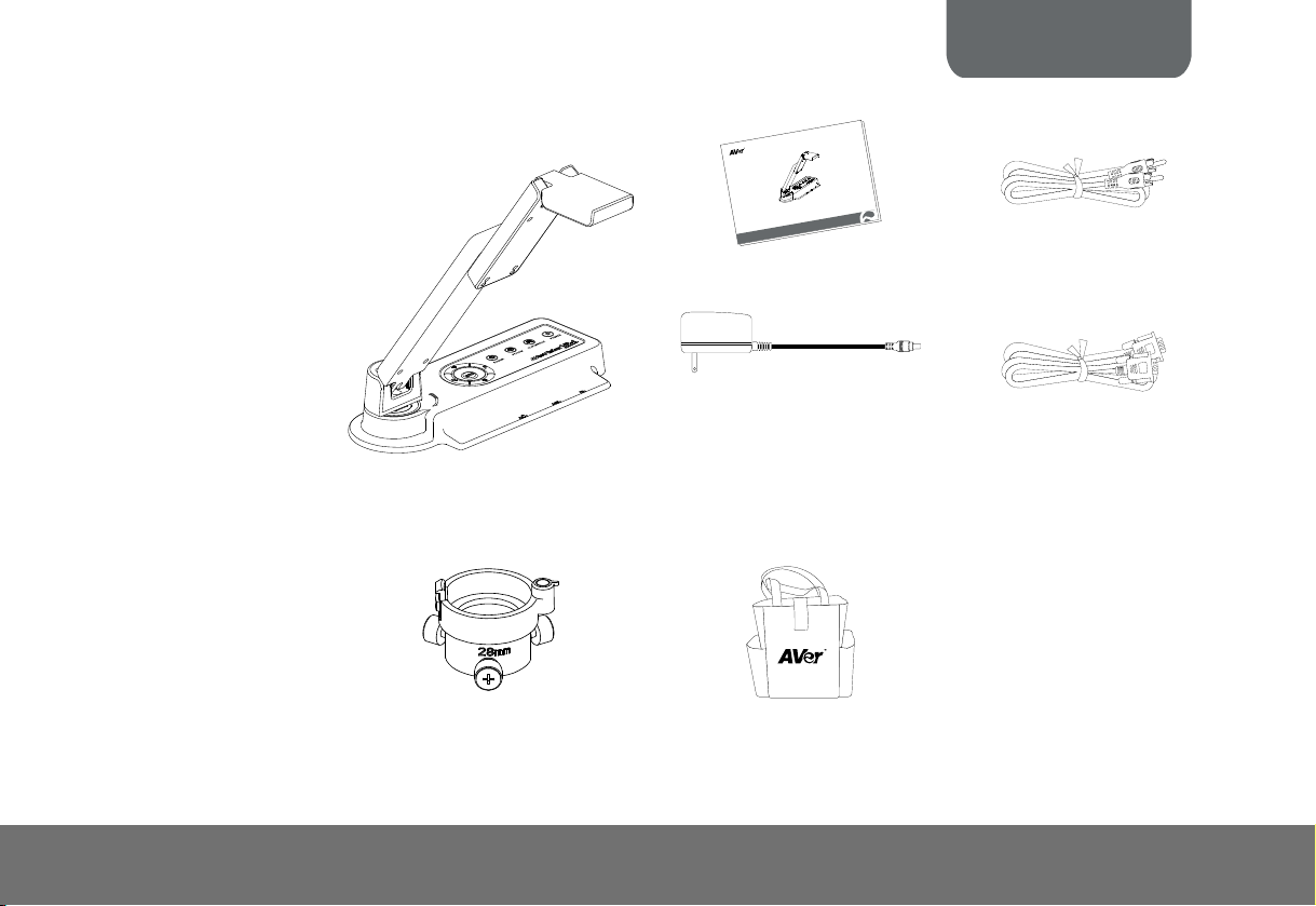
PPaacckkaaggee CCoonntteenntts
s
AVerVision VP-1
OOppttiioonnaall AAcccceessssoorriiees
28mm Microscope Adapter
o
i
is
V
r
e
V
A
n
a
M
r
e
s
U
User Manual
Power Adapter
* The power adapter will vary
depending on the country where
it is sold.
s
Bag
P
V
n
l
a
u
RCA Cable
RGB Cable (VGA Cable)
E-1
Page 6

(1) Camera head
(2) Camera lens
(3) Rear panel
(4) Control panel
(5) Right panel
(6) Paper guide
(7) Arm
(8) TV-RGB switch
(9) Resolution switch
(10) DC 12V port
(11) Composite video
output port
(12) RGB output port
(13) RGB input port
(14) Label slot
(15) Antitheft slot
AAVVeerrVViissiioonn VVPP--11 PPaarrttss
The illustrations below identify the parts of AVerVision VP-1.
Right Panel Rear Panel
(8)
(9)
(11)
(10)
(12)
(13)
(15)
(14)
E-2
Page 7

ENGLISH
TTeecchhnniiccaall SSppeecciiffiiccaattiioonnss
Image
Sensor 1/4" CMOS color image sensor
Total Pixels 2 Mega Pixels
Frame Rate 15 fps (max.)
Analog RGB output
Optics
Lens F 2.8; fl=3.34mm
Focusing Auto
Zooming Digital Zoom: 16X
Shooting Area
Resolution Height (mm) Shooting area (mm)
1280x960(HI) 335 340x255
1024x768(MID) 335 340x255
800x600(LO) 335 340x255
TV 335 340x255
Power
Power Source 100-240V, 50-60Hz
Consumption 7.8 Watts
Input/Output
RGB Input 15-Pins D-sub (VGA)
RGB Output 15-Pins D-sub (VGA)
Composite Video RCA Jack
DC 12V Input Power Jack
1280 x 960 (HI);
1024 x 768 (MID);
800 x 600 (LO)
Dimension
Operating 275mm x 114mm x 335mm
Folded 275mm x 114mm x 70mm
Weight 1.2 kg (about 2.64 lb)
E-3
Page 8

MMaakkiinngg tthhee CCoonnnneeccttiioonnss
The ports on the rear, and right panel of VP-1 enable you to connect the unit to a computer, graphics display monitor or LCD/DLP
projector, TV or other device. Illustrated below are the ports and switches that are located at the rear, and right panel of VP-1 with
their corresponding labels.
Port Description
(1) DC 12V Connect the power adapter into this port.
(1)
(2)
(3)
(4)
(5)
(6)
(7)
(2) Resolution Switch Switch the RGB output resolution to
(3) TV-RGB Switch Switch to output display video either from
(4) TV VIDEO OUT
(RCA/Composite)
(5) RGB OUT Output the signal from the camera, or
(6) RGB IN Input the signal from a computer or other
(7) Antitheft Slot Attach a Kensington compatible security
800x600 (LO), 1024x768 (MID) and
1280x960 (HI).
TV VIDEO OUT, or RGB OUT port.
Output the signal from the camera on TV
or Video equipment.
RGB IN port on a VGA/Mac monitor or
LCD/DLP projector.
sources and pass it through to the RGB
OUT port only.
Connect this port to the VGA output port
of the computer.
lock or antitheft device.
E-4
Page 9

ENGLISH
CCoonnnneeccttiinngg tthhee PPoowweerr AAddaapptteerr
Connect the power adapter to a standard 100V~240V AC power source.
Wall outlet
Power adapter
CCoonnnneeccttiinngg aa TTVV
Locate the VIDEO, or SCART input port of the TV or Video equipment (i.e., VCR) to record your presentation on a videotape and
connect it to TV VIDEO OUT port of VP-1. If you are not sure, please refer to the user manual of the TV or Video equipment. Make
sure the TV/RGB switch is set to TV.
RCA cable
RCA to SCART cabl
(not supplied)
INPUT
VIDEO
e
SCART
Projector
Tel e v i si o n
VCR
E-5
Page 10

CCoonnnneeccttiinngg aa RRGGBB,, MMaacc DDiissppllaayy MMoonniittoorr oorr LLCCDD//DDLLPP PPrroojjeeccttoorr
Locate the RGB input port of the display device and connect it to RGB OUT port of VP-1. If you are not sure, please refer to the user
manual of the device. Make sure the TV/RGB switch is set to RGB.
RGB cable
LCD / MAC monitor
CCoonnnneeccttiinngg aann IIBBMM CCoommppaattiibbllee PPCC oorr MMaacciinnttoosshh CCoommppuutteerr
Locate the VGA output port of the computer or laptop to display your PC presentation on screen and connect it to RGB INPUT port
of VP-1. The video signal from the RGB IN port is streamed to RGB OUT port and displayed on the screen.
Computer
RGB cable
LCD/DLP projector
Laptop
MAC
E-6
Page 11

CCoonnnneeccttiinngg ttoo aa MMiiccrroossccooppee
CCoonnnneeccttiinngg ttoo aa MMiiccrroossccooppee
Connecting the VP-1 to a microscope enables you to examine microscopic
Connecting the VP-1 to a microscope enables you to examine microscopic
objects on a big screen without straining your eyes.
objects on a big screen without straining your eyes.
SSeettttiinngg UUpp AAVVeerrVViissiioonn VVPP--11
SSeettttiinngg UUpp AAVVeerrVViissiioonn VVPP--11
This section provides useful tips on how to setup the VP-1 to meet your needs. This section provides useful tips on how to setup the VP-1 to meet your needs.
UUnnffoollddiinngg tthhee UUnniitt
UUnnffoollddiinngg tthhee UUnniitt
Follow the step by step procedure below to setup the unit. Follow the step by step procedure below to setup the unit.
ENGLISH
(1) Unfold the arm. (2) Turn 90° to the left. (3) Swivel up to the left. (4) Fold the camera down.
E-7
Page 12

OOppeerraattiinngg HHeeiigghhtt && AAnnggllee
90°
The approximate height of the arm should be 335mm and
angled at 53° to display a A4 size landscape document.
PPaappeerr GGuuiiddee
335 mm
90°
150 mm
The A4 paper marks serve as a guide for placing the A4 document under the camera. The approximate shooting area of VP-1 is
340mm x 255mm.
255 mm
340 mm
255 mm
340 mm
E-8
Page 13

ENGLISH
TToouucchh BBuuttttoonn CCoonnttrrooll PPaanneell
The touch button control panel located on the top side of the VP-1 provides quick access to commonly used functions.
(5)
(3)
(4)(1) (2)
(6)
AUTO
POWER
(7)
Function Description
(1) POWER
(2) PC/CAM
(3) FLIP/MIRROR
(4) FREEZE
(5) AUTO
(6) Zoom
(7) Gain
Turn the unit on/standby. To turn off, press hold POWER button for 5 sec.
Switch between Camera and PC mode.
- Camera mode displays the video signal from the built-in camera.
- PC mode displays the video signal from the RGB IN port of VP-1.
Flip the image vertically, horizontally, rotate by 180°, and then return to normal view in camera
mode only.
Toggle to pause or resume the camera.
Automatically adjust the focus and set the white balance.
Digitally zoom in and zoom out the picture up to 1600%.
Make image brighter or darker.
E-9
FREEZEPC/CAM FLIP/MIRROR
Page 14

l
CCoonnttrrool
The LED on the control panel of VP-1 indicates the status of the unit.
PPaanneel
l
LLiigghht
t
CCoolloor
r
Status
Output
TV Red (Flash) Orange Orange (Flash) Red N/A
RGB Red (Flash) Green Green (Flash) Red Red
TTrroouubblleesshhoooottiinng
This section provides many useful tips on how to solve common problems while using the VP-1.
There is no picture on the presentation screen.
1. Check all the connectors again as shown in this manual.
2. Check the on/off switch of the display output device.
3. Verify the setting of the display output device.
4. If you are presenting from a notebook or computer through the display output device, make sure the visualizer is in PC Mode.
For notebook, repeatedly press FN+F5 to toggles between monitors and display the computer image on the presentation screen.
I have set up the VP-1 and checked all the connections as specified in the manual but I cannot get a picture on the
preferred presentation screen.
1. Check the LED light status. Red means the unit is in standby mode. Press the POWER button to turn the unit on and the LED
light will turn green (RGB output) or orange (TV output). .
2. Check the output resolution switch setting. The resolution switch is set to 1024x768 (M) by default. If your output device does not
support this resolution, please change the resolution switch to the supported resolution of your display device.
3. If your display output device is TV or any analog device, please set the TV-RGB switch to TV.
Power Up Power On Freeze Standby PC Mode
g
E-10
Page 15

ENGLISH
The picture on the presentation screen is distorted or the image is blurry.
1. If you discover that the image is blurry or out of focus, just press AUTO to automatically adjust the focus and white balance.
2. If the presentation screen is a bit dim or too bright, use the Gain up
visibility of the image.
and down button on the control panel to adjust the
LLiimmiitteedd WWaarrrraannttyy
For a period of time beginning on the date of purchase of the applicable product and extending as set forth in the “Warranty Period of AVer Product
Purchased” section below, AVer Information Inc. (“AVer”) warrants that the applicable product (“Product”) substantially conforms to AVer’s
documentation for the product and that its manufacture and components are free of defects in material and workmanship under normal use. “You” as
used in this agreement means you individually or the business entity on whose behalf you use or install the product, as applicable. This limited
warranty extends only to You as the original purchaser. Except for the foregoing, the Product is provided “AS IS.” In no event does AVer warrant that
You will be able to operate the Product without problems or interruptions, or that the Product is suitable for your purposes. Your exclusive remedy
and the entire liability of AVer under this paragraph shall be, at AVer’s option, the repair or replacement of the Product with the same or a comparable
product. This warranty does not apply to (a) any Product on which the serial number has been defaced, modified, or removed, or (b) cartons, cases,
batteries, cabinets, tapes, or accessories used with this product. This warranty does not apply to any Product that has suffered damage,
deterioration or malfunction due to (a) accident, abuse, misuse, neglect, fire, water, lightning, or other acts of nature, commercial or industrial use,
unauthorized product modification or failure to follow instructions included with the Product, (b) misapplication of service by someone other than the
manufacturer’s representative, (c) any shipment damages (such claims must be made with the carrier), or (d) any other causes that do not relate to a
Product defect. The Warranty Period of any repaired or replaced Product shall be the longer of (a) the original Warranty Period or (b) thirty (30)
days from the date of delivery of the repaired or replaced product.
Limitations of Warranty
AVer makes no warranties to any third party. You are responsible for all claims, damages, settlements, expenses, and attorneys’ fees with respect to
claims made against You as a result of Your use or misuse of the Product. This warranty applies only if the Product is installed, operated, maintained,
and used in accordance with AVer specifications. Specifically, the warranties do not extend to any failure caused by (i) accident, unusual physical,
electrical, or electromagnetic stress, neglect or misuse, (ii) fluctuations in electrical power beyond AVer specifications, (iii) use of the Product with any
accessories or options not furnished by AVer or its authorized agents, or (iv) installation, alteration, or repair of the Product by anyone other than
AVer or its authorized agents.
E-11
Page 16

Disclaimer of Warranty
EXCEPT AS EXPRESSLY PROVIDED OTHERWISE HEREIN AND TO THE MAXIMUM EXTENT PERMITTED BY APPLICABLE LAW, AVER
DISCLAIMS ALL OTHER WARRANTIES WITH RESPECT TO THE PRODUCT, WHETHER EXPRESS, IMPLIED, STATUTORY OR OTHERWISE,
INCLUDING WITHOUT LIMITATION, SATISFACTORY QUALITY, COURSE OF DEALING, TRADE USAGE OR PRACTICE OR THE IMPLIED
WARRANTIES OF MERCHANTABILITY, FITNESS FOR A PARTICULAR PURPOSE OR NONINFRINGEMENT OF THIRD PARTY RIGHTS.
Limitation of Liability
IN NO EVENT SHALL AVER BE LIABLE FOR INDIRECT, INCIDENTAL, SPECIAL, EXEMPLARY, PUNITIVE, OR CONSEQUENTIAL DAMAGES
OF ANY NATURE INCLUDING, BUT NOT LIMITED TO, LOSS OF PROFITS, DATA, REVENUE, PRODUCTION, OR USE, BUSINESS
INTERRUPTION, OR PROCUREMENT OF SUBSTITUTE GOODS OR SERVICES ARISING OUT OF OR IN CONNECTION WITH THIS LIMITED
WARRANTY, OR THE USE OR PERFORMANCE OF ANY PRODUCT, WHETHER BASED ON CONTRACT OR TORT, INCLUDING NEGLIGENCE,
OR ANY OTHER LEGAL THEORY, EVEN IF AVER HAS ADVISED OF THE POSSIBILITY OF SUCH DAMAGES. AVER’S TOTAL, AGGREGATE
LIABILITY FOR DAMAGES OF ANY NATURE, REGARDLESS OF FORM OF ACTION, SHALL IN NO EVENT EXCEED THE AMOUNT PAID BY
YOU TO AVER FOR THE SPECIFIC PRODUCT UPON WHICH LIABILITY IS BASED.
Governing Law and Your Rights
This warranty gives You specific legal rights; You may also have other rights granted under state law. These rights vary from state to state.
Warranty Period of AVer Product Purchased:
AVerVision VP series : 2 Year Limited Parts and Labor
All AVerVision Accessories: 1 Year Parts and Labor
E-12
 Loading...