

Page 1

System Controller Pro
Quick Installation Guide
Page 2

COPYRIGHT
COPYRIGHT
© 2011 AVer Information Inc. All rights reserved.
No part of this document may be reproduced or transmitted in any form, or by any means without
the prior written permission of AVer Information Inc. AVer Information Inc. reserves the rights to
modify its models, including their characteristics, specifications, accessories and any other
information stated herein without notice. The official printout of any information shall prevail should
there be any discrepancy between the information contained herein and the information contained
in that printout.
TRADEMARKS
“AVer” is a trademark owned by AVer Information Inc. Other trademarks used herein for description
purpose only belong to each of their companies.
NOTICE
SPECIFICATIONS ARE SUBJECT TO CHANGE WITHOUT PRIOR NOTICE.
THE INFORMATION CONTAINED HEREIN IS TO BE CONSIDERED FOR REFERENCE ONLY.
WARNING
TO REDUCE RISK OF FIRE OR ELECTRIC SHOCK. DO NOT EXPOSE THIS APPLIANCE TO
RAIN OR MOISTURE.
WARRANTY VOID FOR ANY UNAUTHORIZED PRODUCT MODIFICATION.
INFORMATION
For more information, please refer to the user manual. User can download the user’s manual from
website http://surveillance.aver.com/download-center .
Page 3
QUICK USER GUIDE
i
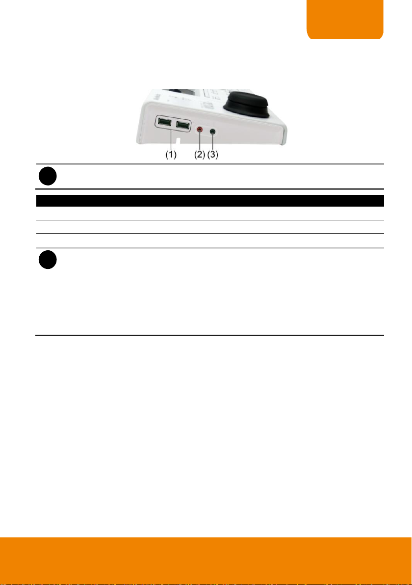
System Controller doesn’t support audio input/output port for SEB5108H/5116H series
DVR.
Function
Description
(1) USB Port
2 * USB ports for connection of keyboard, mouse, or USB flash memory.
(2) Audio Input
For audio input device connection such as microphone.
(3) Audio Output
For audio output device connection such as speaker.
i
- The audio input and output device has its own power supply is necessary.
- The audio input and output port is the same as the audio input and output port on the
DVR system, but audio input and output port of System controller and DVR system
cannot be used at the same time.
- When audio input/output device has connected on the System Controller, the audio
input/output port of the DVR system will be disabled.
- After audio input/output device has removed from the System Controller, please stop
recording and reboot the DVR system to enable the audio input/output port on the DVR
system.
I. Hardware Introduction
Left Side
1
Page 4
i
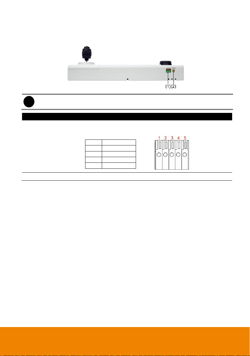
System Controller for SEB5008H/5116H series and EH5108H/5216H series doesn’t
support RS485 port connection.
Function
Description
(1) RS485 Port
For connection of Pelco-D/P PTZ camera and using RS485 to
RS232 converter to connect with DVR system.
1
TX+ 2 TX-
3
RX+ 4 RX- 5 GND
(2) Power Supply Port
For AC power adaptor connection.
Rear Side
2
Page 5
QUICK USER GUIDE
i
- The RS485 connection doesn’t support on SEB5108H/5116H series and
EH5108H/5216H series DVR.
- System Controller supports multiple DVR servers’ connection for NV/SA DVR series
through RS485 connection.
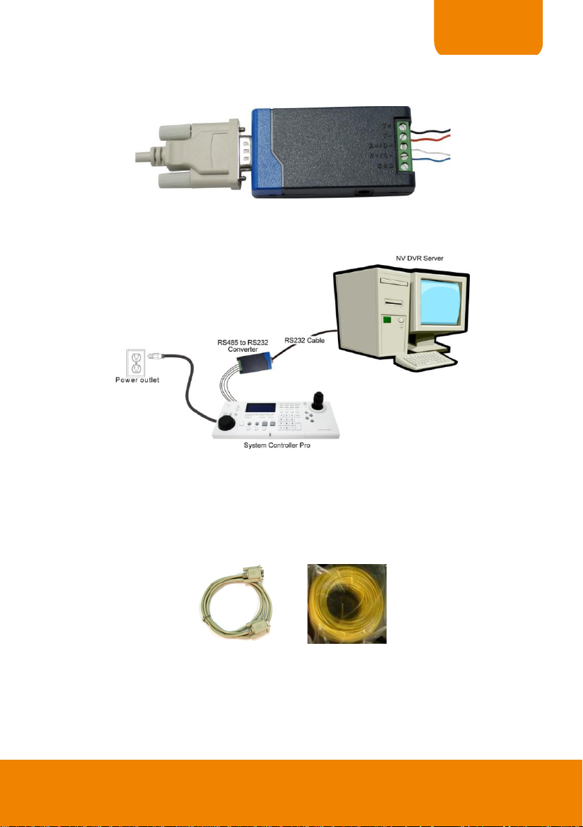
RS232 cable
RS485 to RS232 Converter
(*User can purchase from the dealer
** The RS232 to RS485 Converter needs to support
RS-485 automatic data direction control protocol)
Single core wire
II. Hardware Installation
USB port connection
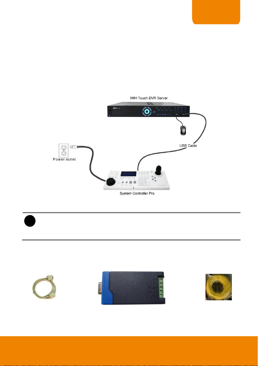
The following is an example of System controller installation for NV, SA, IWH Touch series,
SEB5108H/5116H series, EH5108H/5216H series and CMS server.
1. The DVR/CMS server should be power on and DVR/CMS program is executed.
2. Plug the power cord of the System Controller into power outlet.
3. And then, plug the USB cable that is attached on the System Controller to the USB port of the
DVR/CMS server.
RS485 port connection
RS485 port through RS232 to RS485 Converter
This way of installation is suitable for NV series, CMS server, SA5000, SA6000E, SA6000E Pro,
and SA7000H.
Before starting to make a connection, please prepare the following items:
3
Page 6
RS485 pin hole of System Controller
RS485 to RS232 Converter site
System Controller site
R+
T+
1
R-
T-
2
T+
R+
3
T-
R-
4
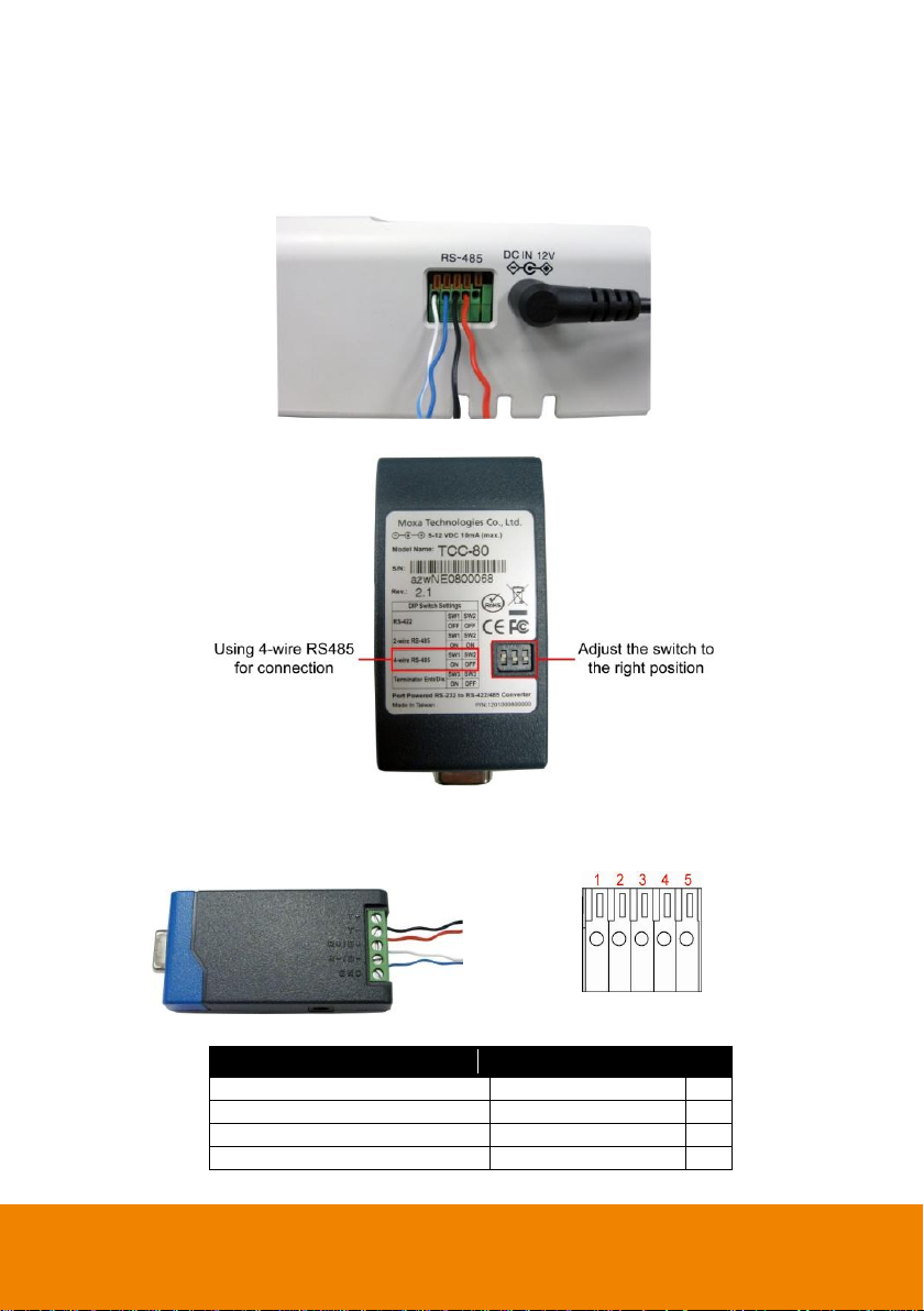
1. Cut the 4 single core wires.
2. Using the screwdriver to press down the orange tenon and insert the single core wire into the
pin hole of the I/O terminal on the System Controller. When the wire is inserted in the end of the
pin hole, release the orange tenon to fix the wire.
3. Set the DIP switch of the RS232 to RS485 converter at 4-wire RS485 setting.
4. Using the screwdriver to lose the pin hole of RS485 to RS232 converter. And then, insert
another side of single core wire into the pin hole of the RS485 to RS232 converter. Using the
screwdriver to screw tight the wire. Please refer to the below table for pin-hole matching:
4
Page 7
QUICK USER GUIDE
RS232 cable
Single core wire
5. Connect the RS232 cable to the RS232 port of the RS485 to RS232 converter.
6. Connect another side of RS232 cable to the RS232 port of the DVR/CMS server.
7. Power on the System Controller.
8. The following figure is an example of the installation illustrate.
9. After hardware installation has completed, please remember to enable the System Controller
function on DVR system.
RS485 port to RS485 port Directly
This way of installation is suitable for SA9000E Pro, SA6000E RACK, SA9416 RACK, and
SA6032E RACK.
Before starting to make a connection, please prepare the following items:
1. The DVR server should power on and DVR program is executed.
2. Cut the 4 lines of single core wire. The length of single core wire depends on the distance
between DVR and System Controller.
3. Using the screwdriver to press down the orange tenon and insert the single core wire cable into
the pin hole of the I/O terminal on the System Controller. When the wire cable is inserted in the
end of the pin hole, release the orange tenon to fix the wire cable. The following table is the pin
hole match for DVR server and System Controller.
5
Page 8

DVR server site
System Controller site
R+
T+ 1 R-
T-
2
T+
R+ 3 T-
R-
4
4. On the DVR server, using the screwdriver to press down the orange tenon and insert the single
core wire cable into the pin hole of the I/O terminal on the DVR server, too. When the wire
cable is inserted in the end of the pin hole, release the orange tenon to fix the wire cable.
5. Power on the System Controller.
6. After hardware installation has complete, please remember to enable the System Controller
function in DVR system.
7. Please remember to switch the System Controller mode to 485 DVR mode before starting
operation.
Connect a PTZ Camera to System Controller Pro
The System Controller Pro can connect the PTZ camera through RS-485 port. The following is an
example of PTZ camera install to System Controller Pro.
1. Connect the PTZ camera to System Controller Pro through the RS-485 interface.
2. Plug the power cord of the System Controller Pro into power outlet.
3. Please select the mode as 485 PTZ on System Controller.
6
Page 9

QUICK USER GUIDE
i
SEB5108H/5116H series and EH5108H/5216H series DVR will detect and install System
Controller automatically, there is no need to enable on the DVR system.
III. Enabling the System Controller
NV/SA/IWH series DVR
Follow the below steps to enable the System Controller function on the DVR server.
1. Start up the DVR program.
2. Click Setup.
3. Select System, the System Setting windows will appear.
4. Click Detail that is next to the System Controller selection.
5. Mark Enable check box to enable the function of the system controller.
6. Select the Model as System Controller Pro (USB connection) or System Controller Pro
485(RS485 connection).
7. For System Controller Pro 485 model, user needs to select the connection Port. If there is
more than one DVR systems are connecting with System Controller, user can assign a DVR ID
as control identity for DVR system in multiple DVRs control.
8. Click OK to complete the setting.
9. If the setting is complete, the LCD of System Controller should display like following figure.
CMS server
Follow the below steps to enable the System Controller function on the CMS server.
1. Start up the CMS program.
2. Click Setup.
3. Select System, the System Setting windows will appear.
4. Click Detail that is next to the System Controller selection.
5. Mark Enable check box to enable the function of the system controller.
6. Select the Model as System Controller Pro (USB connection) or System Controller Pro
485(RS485 connection).
7. For System Controller Pro 485 model, user needs to select the connection Port. If there is
more than one DVR systems are connecting with System Controller, user can assign a Server
ID as a control identity for CMS system in multiple CMSs control.
7
Page 10

i
The following figures might varied from you have seem on the System Controller because
it is due to the DVR server you have connected.
i
If the password function is enabled on System Controller, user needs to enter the password
that user has setup for mode switching.
8. Click OK to complete the setting.
IV. Select the Operation Mode on System Controller
For System Controller to operate the DVR system normally, the connecting mode must correspond
with the way of connection (USB or RS-485) between System Controller and DVR server.
Switching to USB DVR Mode
When System Controller is connected with DVR server through the USB port, please select the
operating mode as USB DVR mode. The following steps describe how to switch from other
operating mode to USB DVR mode.
1. In 485 PTZ menu screen, press button to enter Controller setup screen.
2. Press button to enter Mode setup screen.
8
Page 11

QUICK USER GUIDE
i
If the password function is enabled on System Controller, user needs to enter the password
that user has setup for mode switching.
3. In Mode setup screen, press button to switch the mode to USB DVR mode.
4. Press button to confirm. To cancel the selection, press button. When the
“Complete” message appears on the LCD screen, the mode switch is completed.
Switching to 485 DVR Mode
When System Controller is connected with DVR server through the RS-485 port, please select the
operating mode as 485 DVR mode. If the mode is not 485 DVR mode, please follow the below
steps to switch to 485 DVR mode.
1. In main menu screen, press button to enter Controller setup screen.
2. Press button to enter Mode setup screen.
9
Page 12

i
- The default mode is USB CMS mode
- The 485 PTZ and 485 DVR mode doesn’t support for CMS system.
- Please remember to setup the System Controller Pro as System Controller model on
CMS server.
3. In Mode setup screen, press button to switch the mode to 485 DVR mode.
4. Press button to confirm. To cancel the selection, press button. When the
“Complete” message appears on the LCD screen, the mode switch is completed.
Switching to USB CMS Mode
When the System Controller is connecting with CMS server through the USB port, the System
Controller mode should be in USB CMS mode in order to operate the CMS system. If the mode is
not USB CMS, please follow the below steps to switch to USB CMS mode.
1. In main menu, press and select (system controller setting).
10
Page 13

QUICK USER GUIDE
Current System
Controller Mode
2. In System Controller setting screen, select .
3. In Mode screen, select the . If the current mode is USB-CMS mode already, then the
selection will not show in selection list.
4. Press button to confirm. To cancel the selection, press button. When the
“Complete” message appears on the LCD screen, the mode switch is completed.
11
Page 14

i
- The default mode is USB CMS mode
- The 485 PTZ and 485 DVR mode doesn’t support for CMS server.
- Please remember to setup the System Controller Pro 485 as System Controller model
on CMS server.
Current System
Controller Mode
Switching to 485 CMS Mode
When the System Controller is connecting with CMS server through the 485 port, the System
Controller mode should be in 485 CMS modes in order to operate the CMS system. If the mode is
not 485 CMS mode, please follow the below steps to switch to 485 CMS mode.
1. In main menu, press and select (system controller setting).
2. In System Controller setting screen, select .
3. In Mode screen, select the . If the current mode is 485-CMS mode already, then the
selection will not show in selection list.
12
Page 15

QUICK USER GUIDE
4. Press button to confirm. To cancel the selection, press button. When the
“Complete” message appears on the LCD screen, the mode switch is completed.
V. Familiarizing with LCD Screen
Following will describe the information or icon that display on LCD screen.
Main Menu
Submenu(Multi-function menu)
13
Page 16

VI. Operating the LCD Menu
Main Menu
On the LCD screen, each function is corresponding to the button on the panel of the System
Controller Pro. To select the function, press the correspond button.
Multi-Function Menu
In multi-function menu screen, press the correspond button of the selections to configure/operate.
14
Page 17

QUICK USER GUIDE
i
On NV series DVR system, user can adjust the move speed of the joystick when is in
mouse mode. Please go to Start > Control Panel > Mouse.
Press the Cursor button to
switch the joystick to the
mouse mode.
To go back to the main menu, press the TOP MENU button. Press the BACK button will go back to
the previous screen.
Switching the Joystick to the Mouse mode
The joystick can switch to the mouse mode. User can use to operate the DVR system more easily.
15
Page 18

VII. To Playback the Recorded File on DVR server
To playback the recorded file on surveillance screen.
1. Press button to switch to playback mode. The LCD screen will display “Playback”
message that means the DVR is in playback mode now.
2. The playback time and date selection window will appear on the surveillance screen. Using the
mouse or joystick (press the button to switch to mouse function) to select the time and
date that wants to playback.
3. After selected the time and date to playback, the DVR system will start to playback.
4. Using the Jog/Shuttle button to control the playback speed. Press to enable the
Jog/Shuttle button. To disable the Jog/Shuttle button, press button.
- Jog dial (top part): Rotate in clockwise is forward play frame-by-frame that control by
user. Rotate in counterclockwise is rewinding play frame-by-frame that control by user.
- Shuttle ring (lower part): Rotate in clockwise is play at increase speed of 1x, 2x, 4x, 8x,
16x, and 32x. Rotate in counterclockwise is rewinding playback.
5. To pause the playback, press button. Press again to start playback.
6. To exit playback mode, press button.
VIII. Playback on CMS server
In playback mode, user can playback real-time recorded file from monitored DVR servers,
download from monitored DVR servers and playback, and playback recorded file that has saved on
local hard disk.
Follow the below steps to playback:
1. Press button to switch to playback mode. The LCD screen will switch to the playback
mode.
16
Page 19

QUICK USER GUIDE
i
The date and time selection dialog will be a little different due to the model of DVR server
and the playback mode that user has selected.
2. And, the DVR selection dialog will show up on surveillance screen. Select the DVR server and
click OK. User can use mouse or joystick to select. Press the button on top of joystick to
confirm the selection.
3. After selected the DVR server, the playback mode selection dialog will show up on surveillance
screen. Select the playback mode that user wants and click OK.
4. The playback time and date selection window will appear on the surveillance screen. To select
the date and time, user can use mouse or joystick. Moving joystick to up and down for date
selecting. Moving joystick to left and right for hour selecting. To confirm the selection, press the
button on the top of joystick.
17
Page 20

i
The playback UI will be a little different due to the model of DVR server and the playback
mode that user has selected.
i
The Shuttle ring (lower part) position needs to be back at center to allow Jog dial to
be functional.
i
The button and Jog/Shuttle button doesn’t support in Realtime playback mode.
5. After selected the time and date to playback, the CMS system will start to playback.
6. Using the Jog/Shuttle button to control the playback speed. Press make sure is play
status, and then, press to enable the Jog/Shuttle button. To disable the Jog/Shuttle
button, press button again.
- Jog dial (top part): Rotate in clockwise is forward play frame-by-frame that control by user.
Rotate in counterclockwise is rewinding play frame-by-frame that control by user.
- Shuttle ring (lower part): Rotate in clockwise is play at increase speed of 1x, 2x, 4x, 8x,
16x, and 32x. Rotate in counterclockwise is rewinding playback.
7. To pause the play, press button. Press again to start playback.
8. While playback, user can press button to switch to full screen mode.
18
Page 21

QUICK USER GUIDE
i
The and function button doesn’t support for SEB5108H/5116H series
DVR.
i
- Please select the PTZ camera before starting PTZ operation.
- When PTZ indicator ( ) is green light up, the PTZ operation is available.
9. Press button can capture screen image and save it.
10. To exit playback mode, press button.
IX. Using the Joystick to Operate the PTZ Camera
If the camera has enabled the PTZ function, user can use the System Controller to operate the PTZ
camera. Please select the PTZ camera channel before starting PTZ operation.
1. Press button.
2. On the LCD screen will display Camera Select screen.
3. Using the numeric key pad to enter the camera number (ex: camera 2, enter 2). After entered
the camera number, press Enter button to confirm.
The joystick can move the camera to right, left, up, and down and also to zoom in and out of the
camera.
Panning
Move the joystick to right or left.
19
Page 22

i
IRIS buttons don’t support on SEB5108H/5116H series DVR.
Tilt
Move the joystick to up or down.
Zoom in/out
Rotate the joystick to the clockwise side to zoom in and counterclockwise to zoom out.
To Focus the Object
Press button to focus the object in the distance. Press button to focus the object in
nearby.
Adjusting IRIS of the PTZ Camera
Press or to adjust the PTZ camera lens’ iris.
20
Page 23

P/N: 300AC2CSADNG
July 2011
 Loading...