

Page 1

System Controller Pro
NV series
User’s Manual
July 2011
Page 2

COPYRIGHT
© 2011 AVer Information Inc. All rights reserved.
No part of this document may be reproduced or transmitted in any form, or by any means without
the prior written permission of AVer Information Inc. AVer Information Inc. reserves the rights to
modify its models, including their characteristics, specifications, accessories and any other
information stated herein without notice. The official printout of any information shall prevail should
there be any discrepancy between the information contained herein and the information contained in
that printout.
TRADEMARKS
“AVer” is a trademark owned by AVer Information Inc. Other trademarks used herein for description
purpose only belong to each of their companies.
NOTICE
SPECIFICATIONS ARE SUBJECT TO CHANGE WITHOUT PRIOR NOTICE.
THE INFORMATION CONTAINED HEREIN IS TO BE CONSIDERED FOR REFERENCE ONLY.
WARNING
TO REDUCE RISK OF FIRE OR ELECTRIC SHOCK. DO NOT EXPOSE THIS APPLIANCE TO
RAIN OR MOISTURE.
WARRANTY VOID FOR ANY UNAUTHORIZED PRODUCT MODIFICATION.
INFORMATION
For more information, please refer to the user manual. User can download the user’s
manual from website http://surveillance.aver.com/download-center
Page 3

TABLE OF CONTENTS
CHAPTER 1 INTRODUCTION ........................................................................ 1
1.1 Hardware Introduction ................................................................................. 1
1.1.1 Left Side ..................................................................................................................... 1
1.1.2 Rear Side ................................ ................................................................ ................... 2
1.1.3 Familiarizing with System Controller Panel Buttons .................................................... 3
1.2 Hardware Installation .................................................................................. 7
1.2.1 Connecting with the DVR Server through the USB port ............................................. 7
1.2.2 Connecting with the DVR Server through the RS485 port ........................................... 8
1.2.3 Connect a PTZ Camera to System Controller Pro .................................................... 11
CHAPTER 2 OPERATING THE SYSTEM CONTROLLER PRO................... 12
2.1 Using the System Controller for the First Time .................................................. 12
2.1.1 Upgrading the Firmware of the System Controller ................................................... 13
2.1.2 Switching to USB DVR Mode .................................................................................. 14
2.1.3 Switching to 485 DVR Mode .................................................................................... 16
2.3 Operating the LCD Menu ............................................................................. 19
2.4 Select a Camera ........................................................................................ 21
2.5 Locking System Operation ............................................................................ 22
2.6 Trigger the Alarm Button .............................................................................. 23
2.7 To Playback the Recorded File ....................................................................... 24
2.7 To Playback the Recorded File ....................................................................... 24
2.8 To View the Emap ...................................................................................... 26
2.9 PTZ Operation ........................................................................................ 28
2.9.1 Using the Joystick to Operate the PTZ Camera ........................................................ 28
2.9.2 To Focus the Object ................................................................................................. 29
2.9.4 Setup preset position and Use Preset ...................................................................... 30
Setup Preset Position ........................................................................... 30
Using the Preset Button ........................................................................ 30
2.9.5 Enabling the AutoPan ............................................................................................... 31
2.9.6 Using Digital Zoom ................................................................................................... 33
2.10 Functions in Preview Mode ......................................................................... 34
2.10.1 Select a Monitor Layout ............................................................................................ 34
2.10.2 Camera Setup ................................................................ .......................................... 35
Page 4

Enable a Camera ................................................................................ 35
Enable a Camera View ......................................................................... 36
Adjusting the Hue ................................................................................ 37
Adjusting the Saturation ........................................................................ 38
Adjusting the Brightness ........................................................................ 39
Adjusting the Contrast .......................................................................... 40
Trigger the Relay of IP Camera ............................................................... 41
2.10.3 Server Setup ............................................................................................................ 42
Start Recording .................................................................................. 42
Stop Recording................................................................................... 43
Network Time Synchronization ................................................................ 44
Open Event Log Viewer ........................................................................ 45
2.10.4 Sound Setup ............................................................................................................ 46
2.10.5 Controller Setup ....................................................................................................... 47
Set a Password for System Controller ....................................................... 47
Change the Password of the System Controller ............................................ 49
Set the Timer ..................................................................................... 51
Adjusting the Brightness of LCD Screen ..................................................... 52
Adjusting the Contrast of LCD Screen ....................................................... 53
Enable/disable Code Number Display ....................................................... 54
Operation Mode Selecting ..................................................................... 54
Enable/disable Button Confirmation .......................................................... 55
Viewing System Version Information ......................................................... 56
2.11 Functions in Playback Mode ........................................................................ 57
2.11.1 Select a Monitor Layout ............................................................................................ 57
2.11.2 Camera Setup .......................................................................................................... 58
Enable the De-interlace ........................................................................ 58
2.11.3 Server Setup ............................................................................................................ 59
Open Event Log Viewer ........................................................................ 59
2.11.4 Sound Setup ............................................................................................................ 60
2.11.5 Controller Setup ....................................................................................................... 61
Set a Password for System Controller ....................................................... 61
Change the Password of the System Controller ............................................ 63
Set the Timer ..................................................................................... 65
Page 5

Adjusting the Brightness of LCD Screen ..................................................... 66
Adjusting the Contrast of LCD Screen ....................................................... 67
Enable/disable Code Number Display ....................................................... 68
Viewing System Version Information ......................................................... 69
CHAPTER 3 OPERATING IN PTZ 485 MODE .............................................. 70
3.1 Switching to the PTZ 485 Mode...................................................................... 70
3.2 Select the Protocol of the PTZ Camera ............................................................. 72
3.3 Setup the Baudrate of the PTZ Camera ............................................................ 73
3.4 Controller Setup ........................................................................................ 74
3.4.1 Set a Password for System Controller ...................................................................... 74
3.4.2 Change the Password of the System Controller ....................................................... 76
3.4.3 Set the Timer ............................................................................................................ 78
3.4.4 Adjusting the Brightness of LCD Screen ................................................................... 79
3.4.5 Adjusting the Contrast of LCD Screen ...................................................................... 80
3.4.6 Viewing System Version Information ........................................................................ 81
Page 6

Page 7
Chapter 1 Introduction
Function
Description
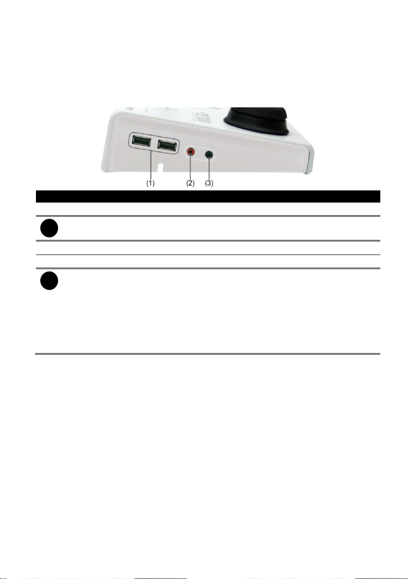
(1) USB Port
2 * USB ports for connection of keyboard, mouse, or USB flash memory.
i
The USB port of the System Controller is the same as the USB port on the DVR system,
but USB of the System Controller and DVR system cannot be used at the same time.
(2) Audio Input
For audio input device connection such as microphone.
(3) Audio Output
For audio output device connection such as speaker.
i
- The audio input and output device has its own power supply is necessary.
- The audio input and output port is same as the audio input and output port on the
DVR system, but audio input and output port of System controller and DVR system
cannot be used at the same time.
- When audio input/output device has connected on the System Controller, the audio
input/output port of the DVR system will be disabled.
- After audio input/output device has removed from the System Controller, please stop
recording and reboot the DVR system to enable the audio input/output port on the
DVR system.
The AVerTM System Controller Pro provides user an easy way to operate DVR server .
1.1 Hardware Introduction
1.1.1 Left Side
1
Page 8
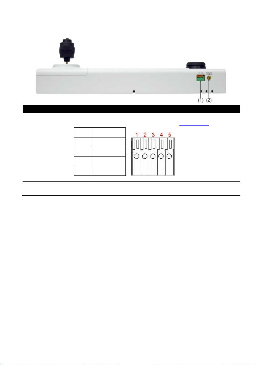
1.1.2 Rear Side
Function
Description
(1) RS485 Port
For connection of Pelco-D/P PTZ camera and using RS485 to RS232
converter to connect with DVR system (see also Chapter 1.2.2).
1
TX+ 2 TX- 3 RX+
4
RX- 5 GND
(2) Power Supply
Port
For AC power adaptor connection.
2
Page 9
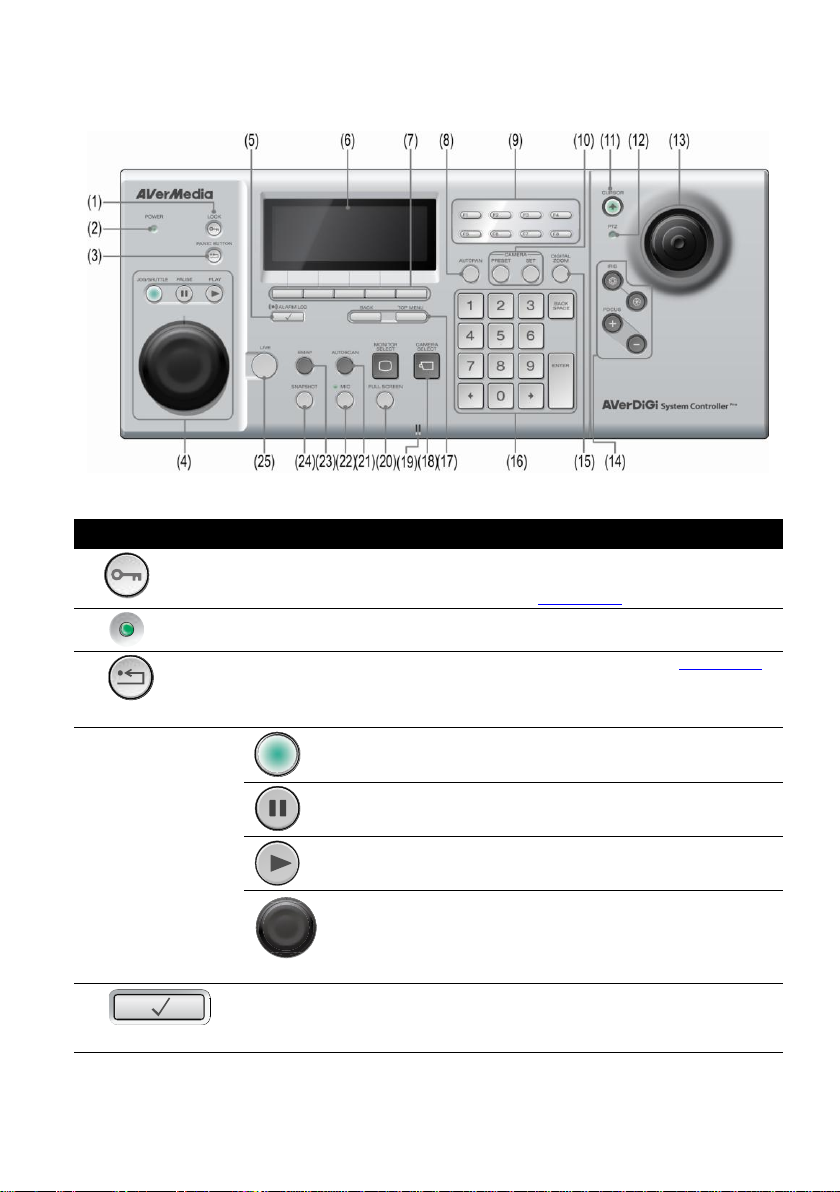
1.1.3 Familiarizing with System Controller Panel Buttons
Function
Description
(1) (Lock)
To lock panel buttons and all operations are lock. Press it to lock and
press again to un-lock. If the system password has been set, please
enter the password to un-lock (see also Chapter 2.5)
(2) (Power)
Lights up when unit is power on.
(3)
(Panic Button)
To trigger the alarm buttons that user has defined (see also Chapter 2.6).
To setup alarm button, please refer to Chapter 5.9 step 5 of NV User’s
Manual. If the alarm button hasn’t been defined, there is no any action
when alarm button is selected to trigger.
(4) Playback Control
Buttons
(Jog/Shuttle)
Enable/disable the jog/shuttle function. When
button lights up is enabling.
(Pause)
To pause the playback.
(Play)
To switch to playback mode and start playback.
(Jog/Shuttle)
- Jog dial (top part): Playback video frame-by-
frame that control by user.
- Shuttle ring (lower part): Playback video at
faster forward or rewind speed that control by
user.
(5)
(Alarm Log)
To call out the alarm log window. To close alarm log window, press the
button again.
System Controller Panel figure
3
Page 10
Function
Description
(6) LCD Screen
To operate the each function in multi-functions menu and view system
related information.
(7) Multi-function
Buttons
Each button represents a function that is corresponding to the function
display on the LCD screen. Press the button and operate it (see also
Chapter 2.10).
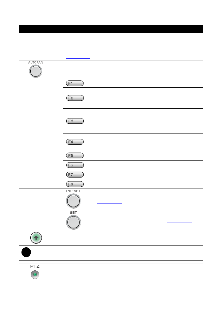
(8)
Enable/disable the PTZ camera move automatically that is based on the
selected camera group preset position number (see also Chapter 2.9.5).
(9) Custom
Function Buttons
To view system information.
Enable/disable recording. Press it to start recording and
press again to stop recording. The authentication password
is required for stop recording. Using numeric key pad to
enter the password and press Enter button to confirm.
Enable/disable network connection. Press it to connect the
network and press again to disconnect the network. The
authentication password is required for stop network
connection. Using numeric key pad to enter the password
and press Enter button to confirm.
To enter system setup mode. The authentication password is
required to enter system setup mode. Using numeric key pad
to enter the password and press Enter button to confirm.
To freeze/un-freeze the surveillance screen. Press it to
freeze the screen and press again to un-freeze.
To extend/fold camera tree window.
Open/close PTZ control panel. Press it to call out the PTZ
control panel and press again to close it.
Call out Logout dialog.
(10) Preset/Set
Button
Move the PTZ camera to the selected preset position (see
also Chapter 2.9.4).
To setup the PTZ preset position (see also Chapter 2.9.4))
(11)
Enable/disable joystick as a mouse function.
i
User can adjust the move speed of the mouse cursor on the Windows system where the
DVR system installed on it. Please go to Start > Control Panel > Mouse.
(12)
When lights up in green, user can use PTZ related operation(see also
Chapter 2.9).
(13) Joystick
To control PTZ camera to left, right, up, down, zoom in, and zoom out.
4
Page 11
Function
Description
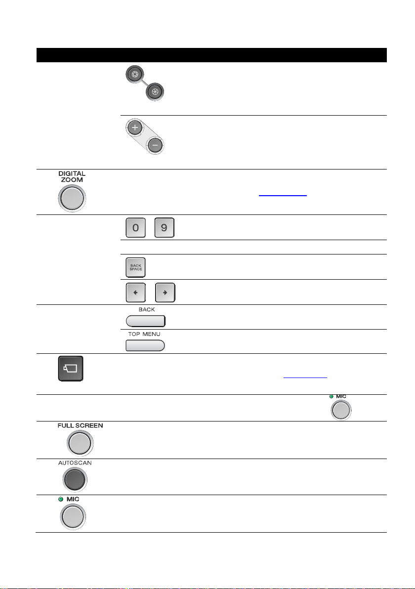
(14) IRIS/Focus
Button
(IRIS)
To adjust the IRIS of camera’s lens.
(Focus)
To adjust the focus of the PTZ camera.
(15)
Enable/disable digital zoom (see also Chapter 2.9.6).
(16) Numeric Key
Pad
~
Number 0~9.
Enter button
For confirmation
To delete the entering information on LCD monitor.
&
Moving the cursor to left or right.
(17) Back /Top Menu
Button
Go back to previous multi-function menu screen.
Go back to the main menu screen.
(18)
(Camera Select)
Using to select the camera channel (see also Chapter 2.4).
(19) Microphone
Build-in microphone for sound recieving. To enable, press button.
(20)
Switch to full screen mode.
(21)
Enable/disable channel display cycle automatically. Press it to start auto
pan and press again to stop.
(22)
When button is pressed and lights up, the System controller can receive
the sound.
5
Page 12

Function
Description
(23)
Switch to Emap mode. In Emap mode, user can select different Emap to
view(see also Chapter 2.8).
(24)
Take a quick photo shot of the surveillance screen and save it.
(25)
Switch to preview/live view mode.
6
Page 13
1.2 Hardware Installation
i
After System Controller has connected to the DVR system, please wait about 3 minutes for
DVR system to automatically detect and install the System Controller.
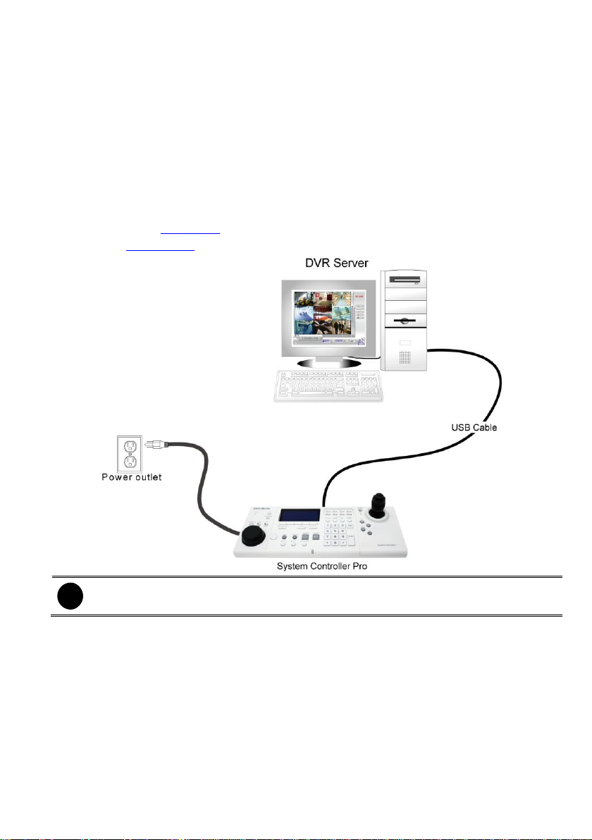
1.2.1 Connecting with the DVR Server through the USB port
The following is an example of System controller installation.
1. The DVR server should be power on and DVR program is executed.
2. Plug the power cord of the System Controller into power outlet.
3. And then, plug the USB cable that is attached on the System Controller to the USB port of the
DVR server.
4. After hardware installation has completed, please remember system controller function on DVR
server (see also Chapter 2.1) and select the correct operating mode on the System Controller
(see also Chapter 2.1.2).
7
Page 14
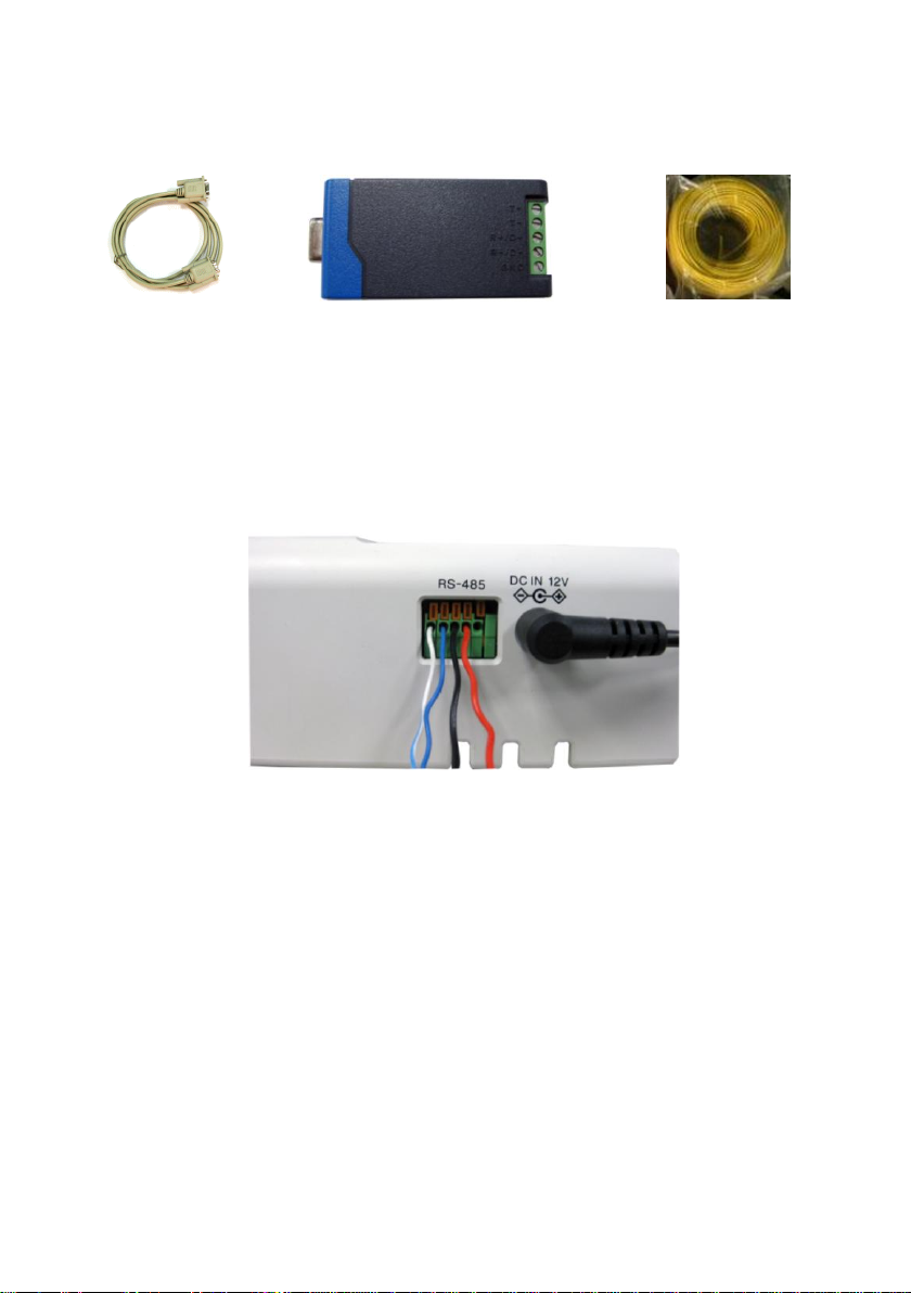
1.2.2 Connecting with the DVR Server through the RS485 port
RS232 cable
RS485 to RS232 Converter
(*User can purchase from the dealer
** The RS232 to RS485 Converter needs
to support RS-485 automatic data
direction control protocol)
Single core wire
Through the RS485 port, user can connect multiple DVR servers with the System Controller.
Before starting to make a connection, please prepare the following items:
1. Cut the 4 single core wires.
2. Using the screwdriver to press down the orange tenon and insert the single core wire into the
pin hole of the I/O terminal on the System Controller. When the wire is inserted in the end of
the pin hole, release the orange tenon to fix the wire.
8
Page 15
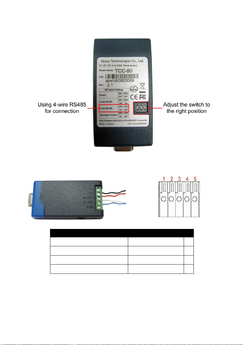
RS485 pin hole of System Controller
RS485 to RS232 Converter site
System Controller site
R+
T+ 1 R-
T-
2
T+
R+ 3 T-
R-
4
3. Set the DIP switch of the RS232 to RS485 converter at 4-wire RS485 setting.
4. Using the screwdriver to lose the pin hole of RS485 to RS232 converter. And then, insert
another side of single core wire into the pin hole of the RS485 to RS232 converter. Using the
screwdriver to screw tight the wire. Please refer to the below table for pin-hole matching:
9
Page 16
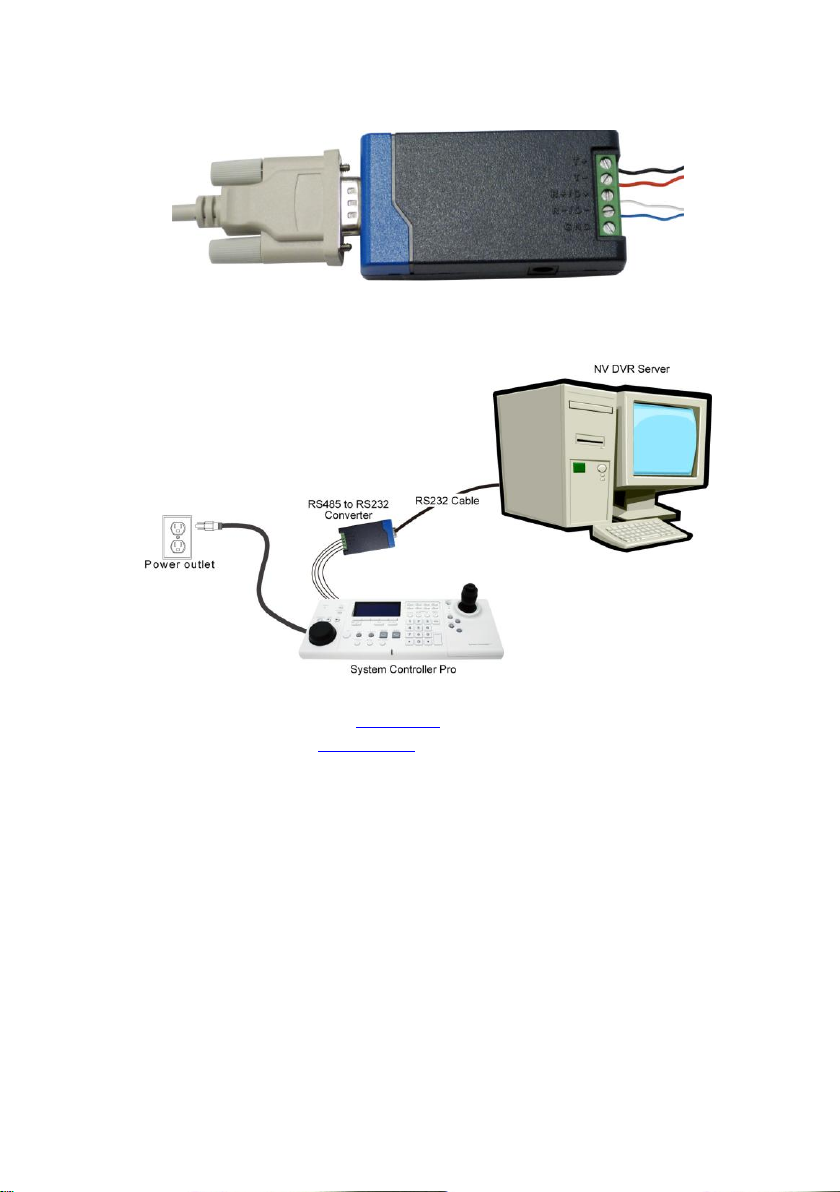
5. Connect the RS232 cable to the RS232 port of the RS485 to RS232 converter.
6. Connect another side of RS232 cable to the RS232 port of the DVR server.
7. Power on the System Controller.
8. The following figure is an example of the installation illustrate.
9. After hardware installation has completed, please remember to enable the system controller
function on DVR server (see also Chapter 2.1) and select the correct operating mode on the
System Controller (see also Chapter 2.1.3).
10
Page 17
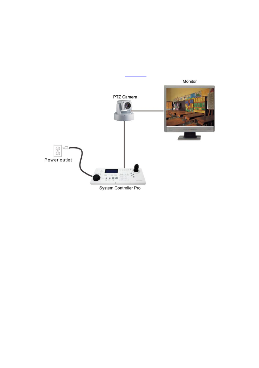
1.2.3 Connect a PTZ Camera to System Controller Pro
The following is an example of PTZ camera install to System Controller Pro.
1. Connect the PTZ camera to System Controller Pro through the RS-485 interface.
2. Plug the power cord of the System Controller Pro into power outlet.
3. After hardware installation has completed, please remember to select the correct operating
mode on the System Controller (see also Chapter 3).
11
Page 18
Chapter 2 Operating the System Controller Pro
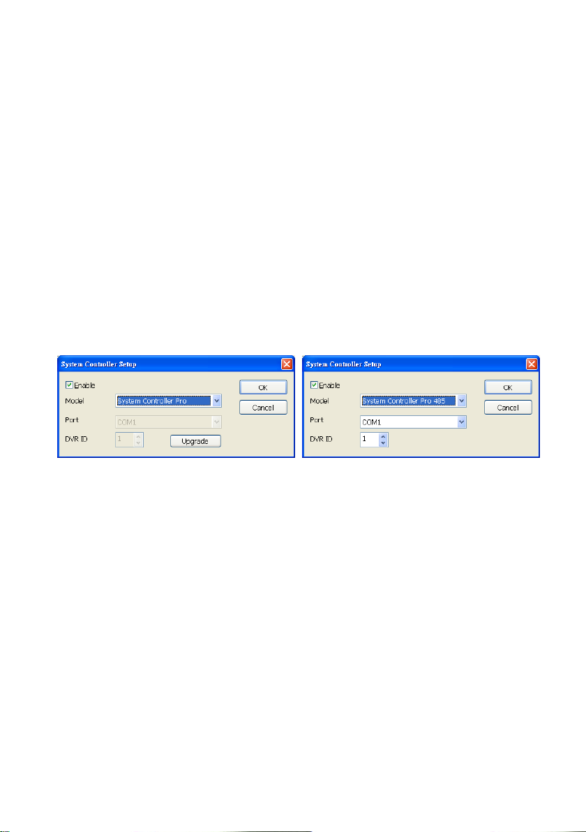
2.1 Using the System Controller for the First Time
For the first time using the System Controller, please enable system controller function on the DVR
server.
1. Start up the DVR program.
2. Click Setup in preview mode.
3. Select System, the System Setting windows will appear.
4. Click Detail that is next to the System Controller section.
5. Mark Enable check box to enable the function of the System Controller.
6. Select the Model as System Controller Pro (USB connection) or System Controller Pro
485(RS485 port connection).
7. For System Controller Pro 485 model, user needs to select the connection Port. If there is more
than one DVR systems are connecting with System Controller, user can assign a DVR ID for the
DVR system as a control identity.
8. Click OK to complete the setting.
9. Please remember to select corresponded operating mode on the System Controller in order to
operate normally.
12
Page 19
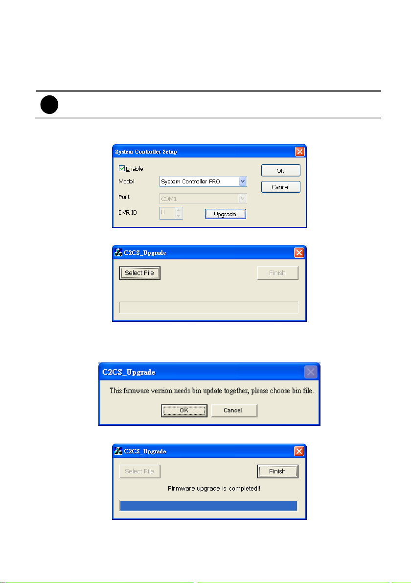
2.1.1 Upgrading the Firmware of the System Controller
i
The upgrade process doesn’t support when System Controller connect to DVR server
through the RS485 port.
User can upgrade the newest firmware of the System Controller. For newest firmware, please
contact your local dealer.
1. In DVR program UI, click Setup > System > Detail of System Controller.
2. Click Upgrade button.
3. Click Select File button to locate the firmware.
4. Select the firmware file and click OK. The upgrade process will start.
5. The upgrade firmware may have more than one file. Therefore, click OK and locate the
firmware file to upgrade another file.
6. When the upgrade process is done, click Finish to complete.
13
Page 20
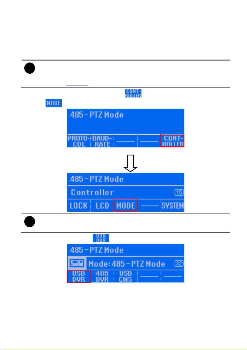
2.1.2 Switching to USB DVR Mode
i
- The default mode is USB DVR mode.
- The USB CMS and 485 CMS mode is supported for CMS application.
- If System Controller is connecting with PTZ camera through RS485 port, please
refer to Chapter 3 for operation description.
i
If the password function is enabled, user needs to enter the password for mode
switching.
When the System Controller is connecting with DVR system through the USB port, the System
Controller mode should be in USB DVR mode in order to operate the DVR system normally. If the
mode is not USB DVR mode, please follow the below steps to switch to USB DVR mode.
1. In 485 PTZ or 485 DVR menu screen, press button to enter Controller setup screen.
2. Press button to enter Mode setup screen.
485-PTZ menu screen
3. In Mode setup screen, press button to switch the mode to USB DVR mode.
14
Page 21
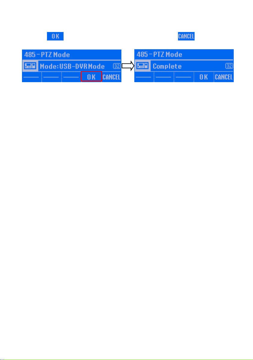
4. Press button to confirm. To cancel the selection, press button. When the
“Complete” message appears on the LCD screen, the mode switch is completed.
15
Page 22
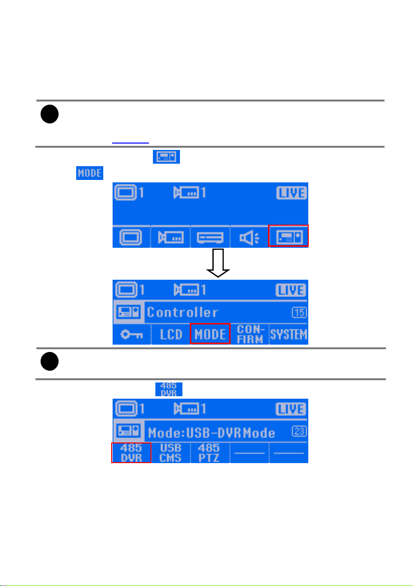
2.1.3 Switching to 485 DVR Mode
i
- The default mode is USB DVR mode
- The USB CMS and 485 CMS mode is supported for CMS application.
- If System Controller is connecting with PTZ camera through RS485 port, please
refer to Chapter 3 for operation description.
i
If the password function is enabled, user needs to enter the password for mode
switching.
When the System Controller is connecting with DVR system through the RS-485 port, the System
Controller mode should be in 485 DVR modes in order to operate the DVR system. If the mode is
not 485 DVR mode, please follow the below steps to switch to 485 DVR mode.
1. In main menu screen, press button to enter Controller setup screen.
2. Press button to enter Mode setup screen.
3. In Mode setup screen, press button to switch the mode to 485 DVR mode.
16
Page 23
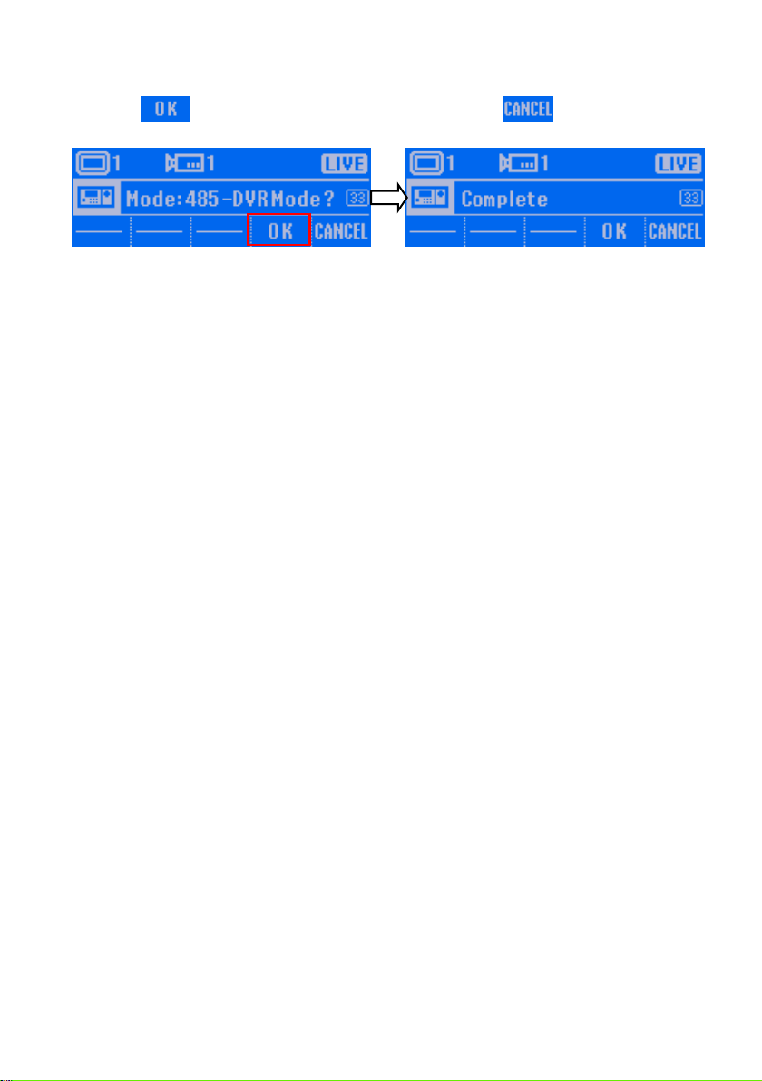
4. Press button to confirm. To cancel the selection, press button. When the
“Complete” message appears on the LCD screen, the mode switch is completed.
17
Page 24
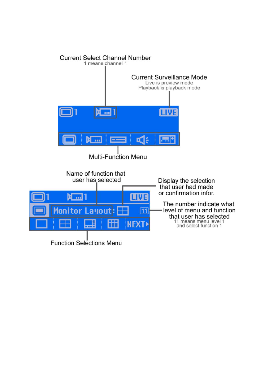
2.2 Familiarizing with LCD Screen
Following will describe the information or icon that display on LCD screen.
Main Menu
Submenu(Multi-function menu)
18
Page 25
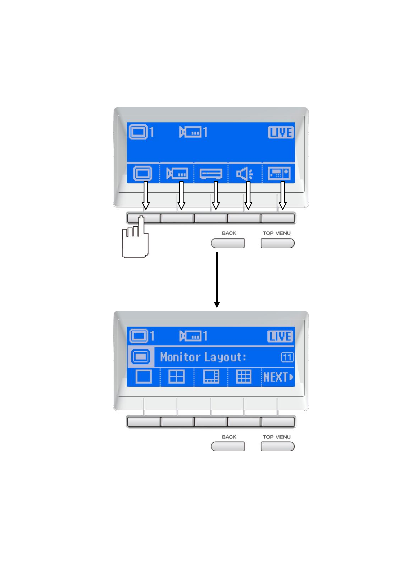
2.3 Operating the LCD Menu
Main Menu
On the LCD screen, each function is corresponding to the button on the panel of the System
Controller Pro. To select the function, press the correspond button.
19
Page 26
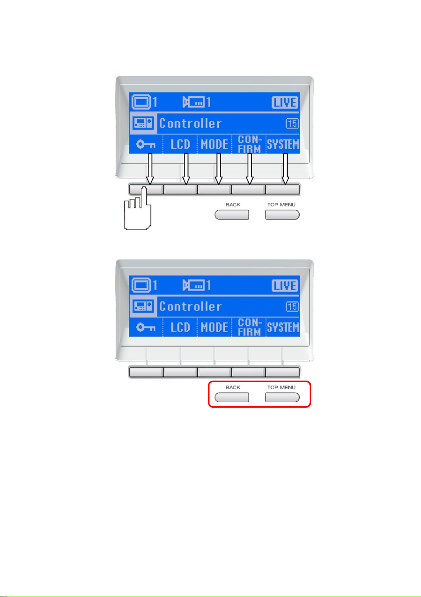
Multi-Function Menu
In multi-function menu screen, press the correspond button of the selections to configure/operate.
To go back to the main menu, press the TOP MENU button. Press the BACK button will go back to
the previous screen.
20
Page 27
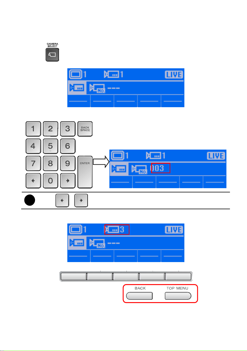
2.4 Select a Camera
i
Using & button can move the cursor to left or right.
Select a camera to view, record, or operate.
1. Press button.
2. On the LCD screen will display Camera Select screen.
3. Using the numeric key pad to enter the camera number (3 numbers, ex: camera 2, enter 002).
After entered the camera number, press Enter button to confirm.
4. User should see the camera number will be 3 on the Camera Select screen. Also the
surveillance screen of DVR will switch to camera 3.
5. To exit the camera select screen, press BACK or TOP MENU button.
21
Page 28

2.5 Locking System Operation
Using the lock button ( ) to lock the System Controller for preventing any unexpected situation
happen during the operator or administer is away from the System Controller.
We strong recommend that enable the password function to enhance the security (see also Set a
Password for System Controller).
1. Press button. The LCD screen will display “System Controller Locked” message.
2. To un-lock, press again and using numeric key pad to enter the password. And then,
press Enter button to un-lock.
22
Page 29

2.6 Trigger the Alarm Button
The panic button ( ) allows user to trigger the defined alarm button manually.
1. Press button and the Alarm Button screen will appear on the LCD screen.
2. Press the number of alarm button to trigger the alarm. When the “Complete” message
appears on the LCD screen, the alarm is triggered.
3. If the “Failure” message appears on the LCD screen, please make sure the alarm button has
been defined. Please refer to the NV user’s manual for Alarm Button’s configuration.
23
Page 30

2.7 To Playback the Recorded File
To playback the recorded file on surveillance screen.
1. Press button to switch to playback mode. The LCD screen will display “Playback”
message that means the DVR is in playback mode now.
2. The playback time and date selection window will appear on the surveillance screen. Using the
mouse or joystick (press the button to switch to mouse function) to select the time and
date that wants to playback.
24
Page 31

3. After selected the time and date to playback, the DVR system will start to playback.
4. Using the Jog/Shuttle button to control the playback speed. Press to enable the
Jog/Shuttle button. To disable the Jog/Shuttle button, press button.
- Jog dial (top part): Rotate in clockwise is forward play frame-by-frame that control by user.
Rotate in counterclockwise is rewinding play frame-by-frame that control by user.
- Shuttle ring (lower part): Rotate in clockwise is play at increase speed of 1x, 2x, 4x, 8x,
16x, and 32x. Rotate in counterclockwise is rewinding playback.
5. To pause the playback, press button. Press again to start playback.
25
Page 32

2.8 To View the Emap
User can select the different Emap to view. The Emap ( ) button is same as the Emap
( ) button on the DVR program UI.
1. Press Emap ( ) button and the Emap UI will appear on surveillance screen.
2. On LCD screen, press the Emap number button (1~8) will switch to the Emap that user has
selected. Press button will go to next page of screen.
3. To close the Emap UI, press button, the DVR program will switch back to preview UI.
26
Page 33

4. Press TOP MENU button to go back to the main menu screen.
27
Page 34

2.9 PTZ Operation
i
- Please select the PTZ camera before starting PTZ operation. Please refer to
Chapter 2.4.
- When PTZ indicator ( ) is green light up, the PTZ operation is available.
If the camera has enabled the PTZ function, user can use the System Controller to operate the PTZ
camera.
2.9.1 Using the Joystick to Operate the PTZ Camera
The joystick can move the camera to right, left, up, and down and also to zoom in and out of the
camera.
Panning
Move the joystick to right or left.
Tilt
Move the joystick to up or down.
28
Page 35

Zoom in/out
Rotate the joystick to the clockwise side to zoom in and counterclockwise to zoom out.
2.9.2 To Focus the Object
Press button to focus the object in the distance. Press button to focus the object in
nearby.
2.9.3 Adjusting the Brightness of the Image
Press and to adjust the IRIS of camera lens.
29
Page 36

2.9.4 Setup preset position and Use Preset
Setup Preset Position
1. Press button and the Camera preset setup screen will appear on LCD screen.
2. Please adjust the lens position of the camera to wanted position.
3. And then, using numeric key pad to enter the preset position number. The numbers of preset
position depends on the support of the PTZ camera.
4. Press Enter button to confirm the setting.
5. When the “Complete” message appears on the LCD screen, the setting is done.
6. To setup another preset position, please repeat the step 2 ~ 4.
Using the Preset Button
Press the button and enter the preset position number, the camera will move to the preset
position that user has setup.
1. Press button and the Preset position screen will appear on LCD screen.
2. Using numeric key pad to enter the number of the preset position and press the Enter button.
3. When the “Complete” message appears on the LCD screen, the function is completed.
30
Page 37

2.9.5 Enabling the AutoPan
Enable/disable the PTZ camera move automatically that is based on the selected camera group
preset position number.
1. Press button and the AutoPan screen will appear on LCD screen.
2. Press the preset position group number button (1-4, 5-8, 9-12, 13-16) and press button
to start auto pan.
3. When the “Complete” message appears on the LCD screen, the function is enabled.
31
Page 38

4. To stop auto pan, press selected preset position group number again and press button.
When the “Complete” message appears on the LCD screen, the function is disabled.
32
Page 39

2.9.6 Using Digital Zoom
To zoom in the selected screen area for viewing.
1. In PTZ camera screen, press button. The message “Complete” will appear on the LCD
screen that is means the digital zoom is enabled.
2. A red frame will appear on the camera screen. Using mouse or joystick (press the button
to switch to mouse function) to click on red frame and drag the area that user wants to zoom in.
3. Right-click mouse or press button on top of joystick to enlarge the selected area.
4. To return to normal view, click or press button on the top of joystick on the enlarge area.
33
Page 40

2.10 Functions in Preview Mode
1. Press the button to enter Monitor
Layout screen.
2. In Monitor Layout screen, press the button
of monitor layout that user wants to view.
3. Press Next button to go to next page. To
go back to previous page, Press Prev.
button.
4. The selected monitor layout will be display.
The surveillance screen will switch the
monitor layout that user has selected.
In the following sections will introduce the each function in preview mode.
2.10.1 Select a Monitor Layout
In Monitor Layout, user can select different screen display mode to view. This function is same as
split-screen buttons ( ) on DVR application UI.
There are 7 types of monitor layout -- , , , , , , .
34
Page 41

2.10.2 Camera Setup
1. First, select the camera to configuration.
Please refer to Chapter 2.4.
2. At main menu screen, press the
button to enter Camera Setup screen.
3. In Camera Setup screen, press
button to enter Camera Enable screen.
4. To enable the camera for viewing and
recording, press button. Press
button to disable the camera.
When the camera has been disabled, the
camera video can’t be view and record.
5. When user sees the “Complete”
message, it means the operation is done.
6. To go back to the Camera setup screen,
press BACK button. To go back to the
main menu screen, press TOP MENU
button.
In Camera setup, user can enable/disable the camera, enable/disable camera video to be display
on the screen, adjust contrast/brightness/saturation/hue, enable/disable de-interlace, and
enable/disable relay of the IP camera.
Enable a Camera
35
Page 42

Enable a Camera View
1. First, select the camera to configuration.
Please refer to Chapter 2.4.
2. At main menu screen, press the
button to enter Camera Setup screen.
3. In Camera Setup screen, press
button to enter Camera Display screen.
4. To enable the camera for viewing and
recording, press button. Press
button to disable the camera.
When the camera has been disabled, the
camera video can’t be view and record.
5. When user sees the “Complete”
message, it means the operation is done.
6. To go back to the Camera setup screen,
press BACK button. To go back to the
main menu screen, press TOP MENU
button.
36
Page 43

Adjusting the Hue
1. First, select the camera to configuration.
Please refer to Chapter 2.4.
2. At main menu screen, press the
button to enter Camera Setup screen.
3. In Camera Setup screen, press
button to enter Attribute screen.
4. In Attribute screen, press button
to enter the Hue adjustment screen.
5. In Hue adjustment screen, enter the
value number( Range is 0~ 100). After
value has entered, press Enter button to
confirm.
6. When user sees the “Complete”
message, it means the operation is
done.
7. After complete the adjustment, the value
of hue will be display on the LCD screen.
To go back to previous menu screen,
press BACK button. To go back to main
menu, press TOP MENU.
37
Page 44

Adjusting the Saturation
1. First, select the camera to configuration.
Please refer to Chapter 2.4.
2. At main menu screen, press the
button to enter Camera Setup screen.
3. In Camera Setup screen, press
button to enter Attribute screen.
4. In Attribute screen, press button
to enter the Saturation adjustment
screen.
5. In Saturation adjustment screen, enter
the value number (Range is 0~ 100).
After value has entered, press Enter
button to confirm.
6. When user sees the “Complete”
message, it means the operation is
done.
7. After complete the adjustment, the value
of hue will be display on the LCD screen.
To go back to previous menu screen,
press BACK button. To go back to main
menu, press TOP MENU.
38
Page 45

Adjusting the Brightness
1. First, select the camera to configuration.
Please refer to Chapter 2.4.
2. At main menu screen, press the
button to enter Camera Setup screen.
3. In Camera Setup screen, press
button to enter Attribute screen.
4. In Attribute screen, press button
to enter the Brightness adjustment
screen.
5. In Brightness adjustment screen, enter
the value number (Range is 1~ 100).
After value has entered, press Enter
button to confirm.
6. When user sees the “Complete”
message, it means the operation is
done.
7. After complete the adjustment, the value
of hue will be display on the LCD screen.
To go back to previous menu screen,
press BACK button. To go back to main
menu, press TOP MENU.
39
Page 46

Adjusting the Contrast
1. First, select the camera to configuration.
Please refer to Chapter 2.4.
2. At main menu screen, press the
button to enter Camera Setup screen.
3. In Camera Setup screen, press
button to enter Attribute screen.
4. In Attribute screen, press button
to enter the Contrast adjustment
screen.
5. In Contrast adjustment screen, enter the
value number (Range is 1~ 100). After
value has entered, press Enter button to
confirm.
6. When user sees the “Complete”
message, it means the operation is
done.
7. After complete the adjustment, the value
of hue will be display on the LCD screen.
To go back to previous menu screen,
press BACK button. To go back to main
menu, press TOP MENU.
40
Page 47

Trigger the Relay of IP Camera
1. First, select the camera to configuration.
Please refer to Chapter 2.4.
2. At main menu screen, press the
button to enter Camera Setup screen.
3. In Camera Setup screen, press
button to enter IP-CAM Output screen.
4. In IP-CAM Output screen, press 1 ~ 4
button to trigger relay 1~4.
5. When user sees the “Complete”
message, it means the operation is
done. To go back to previous menu
screen, press BACK button. To go back
to main menu, press TOP MENU.
41
Page 48

2.10.3 Server Setup
1. At main menu screen, press the
button to enter Server Setup screen.
2. In Server Setup screen, press
button to start recording.
3. When user sees the “Complete”
message, it means the operation is
done. To go back to previous menu
screen, press BACK button. To go back
to main menu, press TOP MENU.
4. When recording is enabled, the icon
will show up on the surveillance screen.
In Server setup, user can start recording, stop recording, execute network time synchronization, and
call out event log viewer windows.
Start Recording
This function is same as press F2 button (see also (9)Custom Button Function in Chapter 1.1.3)
42
Page 49

Stop Recording
1. At main menu screen, press the
button to enter Server Setup screen.
2. In Server Setup screen, press
button to stop recording.
3. The authorization dialog will show up on
surveillance screen. Enter the authorize
password and click OK to stop recording.
This function is same as press F2 button (see also (9)Custom Button Function in Chapter 1.1.3)
43
Page 50

Network Time Synchronization
1. At main menu screen, press the
button to enter Server Setup screen.
2. Please stop recording before start
network time synchronization. Press
button in Server setup screen
(see also Stop Recording).
3. After stop recording, press
button to start time synchronization.
To adjust the DVR system time through the network time server that user has configured on DVR
server.
44
Page 51

Open Event Log Viewer
1. At main menu screen, press the
button to enter Server Setup screen.
2. In Server Setup screen, press
button.
3. The event log viewer window will show
up on the surveillance screen.
To call out the event log viewer window. This function is same as press button on
DVR program UI.
45
Page 52

2.10.4 Sound Setup
1. At main menu screen, press the
button to enter Sound setup screen.
2. Press s and button to
increase or decrease the volume.
3. To disable the sound, press
button.
4. Press button to complete the
setup. To cancel, press button.
In Sound setup, user can enable/disable sound and adjust volume output of the System Controller.
46
Page 53

2.10.5 Controller Setup
1. At main menu screen, press the
button to enter Controller setup screen.
2. Press button to enter System
Lock screen.
3. Press button to enter the
Password setup screen.
In Controller setup, user can configure the parameters of the System Controller Pro.
Set a Password for System Controller
To setup the password of System Controller for security issue.
47
Page 54

4. Press button to enable password
function.
5. The password enter screen will appear.
Using numeric key pad to enter the
password (6 numbers). After entered
password, press Enter button.
6. When user sees the “Complete”
message, it means the operation is
done.
48
Page 55

Change the Password of the System Controller
i
The password function will be enabling after password changed.
1. At main menu screen, press the
button to enter Controller setup screen.
2. Press button to enter System
Lock screen.
3. Press button to enter the
Password setup screen.
4. Press button and the Password
Change screen will appear.
5. Using numeric key pad to enter the
current password (6 numbers). After
entered password, press Enter button.
49
Page 56

6. After entered the current password, the
new password screen will appear.
7. Using numeric key pad to enter the new
password (6 numbers) and press Enter
to confirm.
8. After entered the new password, the
password confirm screen will appear.
9. Using numeric key pad to re-enter the
new password and press Enter button to
confirm.
10. When user sees the “Complete”
message, it means the operation is
done.
50
Page 57

Set the Timer
1. At main menu screen, press the
button to enter Controller setup screen.
2. Press button to enter System
Lock screen.
3. Press button to enter the Timer
setup screen.
4. Press button to enable the timer.
Press again will disable the timer.
5. Press s and button to
adjust the time.
6. Press button to confirm the
setting. To cancel, press button.
Set a System Controller idle time period to switch to rest status.
51
Page 58

Adjusting the Brightness of LCD Screen
1. At main menu screen, press the
button to enter Controller setup screen.
2. Press button to enter LCD setup
screen.
3. Press button to enter the Back light
brightness setup screen.
4. Press s and button to
adjust the brightness. Press
button to confirm the setting. To cancel,
press button.
To adjust the back light brightness of the LCD screen.
52
Page 59

Adjusting the Contrast of LCD Screen
1. At main menu screen, press the
button to enter Controller setup screen.
2. Press button to enter LCD setup
screen.
3. Press button to enter the Contrast
setup screen.
4. Press and button to
adjust the brightness.
5. Press button to confirm the
setting. To cancel, press button.
53
Page 60

Enable/disable Code Number Display
1. At main menu screen, press the
button to enter Controller setup screen.
2. Press button to enter LCD setup
screen.
3. Press button to enter the Code
number setup screen.
4. Press button to enable the code
number display. Press button
again will disable the code number
display.
5. Press button to confirm the
setting. To cancel, press button.
Operation Mode Selecting
System Controller supports USB DVR and 485 DVR mode for NV DVR server. User can depend on
the way of connection to select operation mode. Please refer to Chapter 2.1.2 and Chapter 2.1.3 for
details.
54
Page 61

Enable/disable Button Confirmation
1. At main menu screen, press the
button to enter Controller setup screen.
2. Press button to enter Button
Confirmation setup screen.
3. Press button to enter Function
button setup screen.
4. Press button to enable or disable
the button confirmation function. Press
button to confirm the setting. To
cancel, press button.
5. Press button again will disable or
enable the function.
User can enable/disable to display a confirmation screen when press custom function buttons
(F1~F8) and Alarm button.
55
Page 62

Viewing System Version Information
1. At main menu screen, press the
button to enter Controller setup screen.
2. Press button to enter System
Menu screen.
3. Press button to view current
system version. Press button
exit from the screen.
56
Page 63

2.11 Functions in Playback Mode
1. Press the button to enter
Monitor Layout screen.
2. In Monitor Layout screen, press the
button of monitor layout that user wants
to view.
3. Press Next button to go to next page. To
go back to previous page, Press Prev.
button.
4. The selected monitor layout will be
display. The surveillance screen will
switch the monitor layout that user has
selected.
In the following sections will introduce the each function in playback mode.
2.11.1 Select a Monitor Layout
In Monitor Layout, user can select different screen display mode to view. This function is same as
split-screen buttons ( ) on DVR application UI.
There are 7 types of monitor layout -- , , , , , , .
57
Page 64

2.11.2 Camera Setup
i
Camera Enable ( ), Display ( ), Attribute ( ), and IP-CAM Output
function ( ) are not supported.
1. At main menu screen, press the
button to enter Camera Setup screen.
2. In Camera Setup screen, press
button to enter De-interlace screen.
3. In De-interlace screen, press 1 button to
if you are capturing motionless picture.
Press 2 button if it captures lots of
movement. To disable de-interlace, press
OFF button.
4. When user sees the “Complete”
message, it means the operation is
done. To go back to previous menu
screen, press BACK button. To go back
to main menu, press TOP MENU.
In Camera setup, user can enable/disable de-interlace function.
Enable the De-interlace
58
Page 65

2.11.3 Server Setup
1. At main menu screen, press the
button to enter Server Setup screen.
2. In Server Setup screen, press
button.
3. The event log viewer window will show
up on the surveillance screen.
In Server setup, user can call out event log viewer windows.
Open Event Log Viewer
To call out the event log viewer window. This function is same as press button on
DVR program UI.
59
Page 66

2.11.4 Sound Setup
1. At main menu screen, press the
button to enter Sound setup screen.
2. Press s and button to
increase or decrease the volume.
3. To disable the sound, press
button.
4. Press button to complete the
setup. To cancel, press button.
In Sound setup, user can enable/disable sound and adjust volume output of the System Controller.
60
Page 67

2.11.5 Controller Setup
i
The Button Confirmation ( ) and Mode ( ) function are not supported.
1. At main menu screen, press the
button to enter Controller setup screen.
2. Press button to enter System
Lock screen.
In Controller setup, user can configure the parameters of the System Controller Pro.
Set a Password for System Controller
To setup the password of System Controller for security issue.
61
Page 68

3. Press button to enter the
Password setup screen.
4. Press button to enable password
function.
5. The password enter screen will appear.
Using numeric key pad to enter the
password (6 numbers). After entered
password, press Enter button.
6. When user sees the “Complete”
message, it means the operation is
done.
62
Page 69

Change the Password of the System Controller
i
The password function will be enabling after password changed.
1. At main menu screen, press the
button to enter Controller setup screen.
2. Press button to enter System
Lock screen.
3. Press button to enter the
Password setup screen.
4. Press button and the Password
Change screen will appear.
5. Using numeric key pad to enter the
current password (6 numbers). After
entered password, press Enter button.
63
Page 70

6. After entered the current password, the
new password screen will appear.
7. Using numeric key pad to enter the new
password (6 numbers) and press Enter
to confirm.
8. After entered the new password, the
password confirm screen will appear.
9. Using numeric key pad to re-enter the
new password and press Enter button to
confirm.
10. When user sees the “Complete”
message, it means the operation is
done.
64
Page 71

Set the Timer
1. At main menu screen, press the
button to enter Controller setup screen.
2. Press button to enter System
Lock screen.
3. Press button to enter the Timer
setup screen.
4. Press button to enable the timer.
Press again will disable the timer.
5. Press s and button to
adjust the time.
6. Press button to confirm the
setting. To cancel, press button.
Set a period time for System Controller idling over the setup time to switch to rest status.
65
Page 72

Adjusting the Brightness of LCD Screen
1. At main menu screen, press the
button to enter Controller setup screen.
2. Press button to enter LCD setup
screen.
3. Press button to enter the Back light
brightness setup screen.
4. Press s and button to
adjust the brightness. Press
button to confirm the setting. To cancel,
press button.
To adjust the back light brightness of the LCD screen.
66
Page 73

Adjusting the Contrast of LCD Screen
1. At main menu screen, press the
button to enter Controller setup screen.
2. Press button to enter LCD setup
screen.
3. Press button to enter the Contrast
setup screen.
4. Press and button to
adjust the brightness.
5. Press button to confirm the
setting. To cancel, press button.
67
Page 74

Enable/disable Code Number Display
1. At main menu screen, press the
button to enter Controller setup screen.
2. Press button to enter LCD setup
screen.
3. Press button to enter the Code
number setup screen.
4. Press button to enable the code
number display. Press button
again will disable the code number
display.
5. Press button to confirm the
setting. To cancel, press button.
68
Page 75

Viewing System Version Information
1. At main menu screen, press the
button to enter Controller setup screen.
2. Press button to enter System
Menu screen.
3. Press button to view current
system version. Press button
exit from the screen.
69
Page 76

Chapter 3 Operating in PTZ 485 Mode
i
To operate PTZ camera, please refer to Chapter 2.9.
i
- The default mode is USB DVR mode
- The USB CMS and 485 DVR mode is not supported in current version.
- If System Controller is connecting with DVR system, please refer to Chapter 2 for
operation description.
i
If the password function is enabled, user needs to enter the password for mode
switching.
The PTZ 485 mode is to control the PTZ camera that is directly connected with System Controller
through the RS485 port.
3.1 Switching to the PTZ 485 Mode
Before starting to operate the PTZ camera, please switch to the PTZ 485 mode.
1. In main menu screen, press button to enter Controller setup screen.
2. Press button to enter Mode setup screen.
3. In Mode setup screen, press button to switch the mode to 485 PTZ mode.
70
Page 77

4. Press button to confirm. To cancel the selection, press button. When the
“Complete” message appears on the LCD screen, the mode switch is completed.
71
Page 78

3.2 Select the Protocol of the PTZ Camera
Selecting the PTZ camera – Pelco-P or Pelco-D.
1. In 485 PTZ mode menu screen, press button to enter the Protocol setup screen.
2. In Protocol setup screen, press button to select the protocol. And then, press
button to confirm. To cancel the selection, press button. When the “Complete”
message appears on the LCD screen, the mode switch is completed.
72
Page 79

3.3 Setup the Baud Rate of the PTZ Camera
Selecting the baud rate of the PTZ camera.
1. In 485 PTZ mode menu screen, press button to enter the Protocol setup screen.
2. In Baudrate setup screen, press baudrate button and press button to confirm. To
cancel the selection, press button. When the “Complete” message appears on the
LCD screen, the mode switch is completed.
73
Page 80

3.4 Controller Setup
1. At main menu screen, press the
button to enter Controller setup screen.
2. Press button to enter Lock setup
screen.
In Controller setup, user can configure the password, timer, brightness and contrast of the LCD
screen, switch mode, and view system version.
3.4.1 Set a Password for System Controller
To setup the password of System Controller for security issue.
74
Page 81

3. Press button to enter the
Password setup screen.
4. Press button to enable password
function.
5. The password enter screen will appear.
Using numeric key pad to enter the
password (6 numbers). After entered
password, press Enter button.
6. When user sees the “Complete”
message, it means the operation is
done.
75
Page 82

3.4.2 Change the Password of the System Controller
i
The password function will be enabling after password changed.
1. At main menu screen, press the
button to enter Controller setup screen.
2. Press button to enter System
Lock screen.
3. Press button to enter the
Password setup screen.
4. Press button and the Password
Change screen will appear.
5. Using numeric key pad to enter the
current password (6 numbers). After
entered password, press Enter button.
76
Page 83

6. After entered the current password, the
new password screen will appear.
7. Using numeric key pad to enter the new
password (6 numbers) and press Enter
to confirm.
8. After entered the new password, the
password confirm screen will appear.
9. Using numeric key pad to re-enter the
new password and press Enter button to
confirm.
10. When user sees the “Complete”
message, it means the operation is
done.
77
Page 84

3.4.3 Set the Timer
1. At main menu screen, press the
button to enter Controller setup screen.
2. Press button to enter System
Lock screen.
3. Press button to enter the Timer
setup screen.
4. Press button to enable the timer.
Press again will disable the timer.
5. Press s and button to
adjust the time.
6. Press button to confirm the
setting. To cancel, press button.
Set a period time for System Controller idling over the setup time to switch to rest status.
78
Page 85

3.4.4 Adjusting the Brightness of LCD Screen
5. At main menu screen, press the
button to enter Controller setup screen.
6. Press button to enter LCD setup
screen.
7. Press button to enter the Back
light brightness setup screen.
8. Press s and button to
adjust the brightness. Press
button to confirm the setting. To cancel,
press button.
To adjust the back light brightness of the LCD screen.
79
Page 86

3.4.5 Adjusting the Contrast of LCD Screen
6. At main menu screen, press the
button to enter Controller setup screen.
7. Press button to enter LCD setup
screen.
8. Press button to enter the
Contrast setup screen.
9. Press and button to
adjust the brightness.
10. Press button to confirm the
setting. To cancel, press button.
80
Page 87

3.4.6 Viewing System Version Information
1. At main menu screen, press the
button to enter Controller setup screen.
2. Press button to enter System
Menu screen.
3. Press button to view current
system version. Press button
exit from the screen.
81
Page 88

AVer Information Inc.
Taiwan & International
5F., No.135, Jian 1st Rd., Zhonghe Dist., New Taipei City, Taiwan
TEL: 886-2-2226-3630
FAX: 886-2-2226-7241
Web Site: http://surveillance.aver.com/
 Loading...