

AVer SF2121H-R User Manual
AVer SF2121H-R
User Manual

TTaabbllee ooff CCoonntteennttss
Important Safeguard ....................................................................... 1
Package Contents............................................................................ 2
Optional Accessory ......................................................................... 2
IP Camera Parts ............................................................................... 3
Front Panel ............................................................................................. 3
Rear Panel .............................................................................................. 3
CS-Mount Lens ....................................................................................... 3
Setting Up the IP Camera ................................................................ 4
Connecting the Lens ............................................................................... 4
Deploying Network .................................................................................. 4
Network Connection via Ethernet Switch .......................................... 4
Power over Ethernet Connection....................................................... 5
PoE Enabled Switch Connection Diagram ..................................... 5
PoE Injector Connection Diagram .................................................. 5
RJ45 LED ......................................................................................... 5
Connecting the External Devices to I/O Terminal Block .......................... 6
Adjusting the CS-mount Ring .................................................................. 6
Focusing the IP Camera with BNC Monitor .................................. 8
Setting up the IP Camera over the Internet ................................... 9
Using DHCP Server/Router Network ...................................................... 9
Using NON-DHCP Server/Router Network ........................................... 10
Configuring the Internet Explorer Security Setting ................... 12
Using the IP Camera Browser Interface ...................................... 13
Preview ................................................................................................. 13
Using Media Player to view IP Camera ........................................ 15
System > General ................................................................................. 15
System > General > Maintenance ......................................................... 15
To Upgrade the IP Camera Firmware .............................................. 16
System > General > Date & Time ......................................................... 17
System > General > System Log .......................................................... 18
System > User Management ................................................................ 18
System > User Management > Account ................................................ 18
To Create a User Account ............................................................... 18
To Delete or Edit a User Account..................................................... 19
System > User Management > Connection .......................................... 20
T o Add Filter .................................................................................... 20
System > Network ................................................................................. 21
System > Network > Setting ................................................................. 21
System > Network > Server .................................................................. 22
System > Network > DDNS .................................................................. 23
System > Network > QoS ..................................................................... 23
System > Network > Others .................................................................. 24
System > Image .................................................................................... 24

System > Image > OSD ........................................................................ 24
System > Image > Preference .............................................................. 25
System > Image > Exposure ................................................................. 26
System > Image > Advanced ................................................................ 27
System > Image > Privacy Mask ........................................................... 28
System > Video Stream ........................................................................ 28
System > Audio ..................................................................................... 29
System > SD Card > Management ....................................................... 30
System > SD Card > FileSearch ........................................................... 31
Application > Motion Detection ............................................................. 31
To Set the Motion Detection ............................................................ 31
Application > Patrol ............................................................................... 32
To Setup the Patrol .......................................................................... 32
Event ..................................................................................................... 33
To Setup the Event .......................................................................... 34
Status Information ................................................................................. 35
Technical Specifications ............................................................... 35
Federal Communications Commission Statement (Class B) .... 37
Class B (EMC) ................................................................................ 38
COPYRIGHT ................................................................................... 38
NOTICE ........................................................................................... 38
WARNING ....................................................................................... 38
Limited Warranty ........................................................................... 38
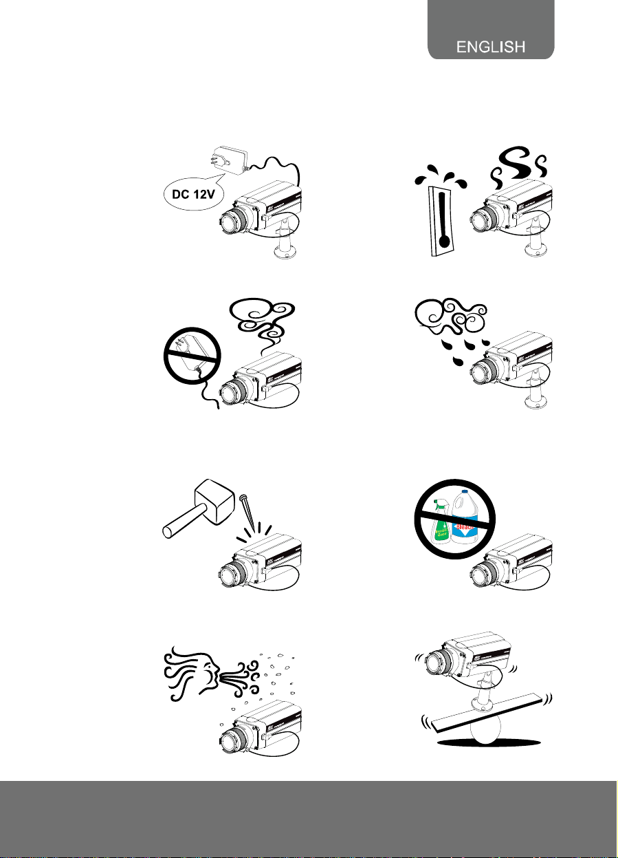
IImmppoorrttaanntt SSaaffeegguuaarrdd
- Do not use power supply with different
voltage than the one supplied in this unit.
- Unplug the power of this unit as soon as
smoke or unusual odor is detected.
- Do not attempt to open the housing or
service this unit by yourself. Always refer
all servicing to qualified service
personnel.
- Keep this unit away from direct heat or
sunlight.
- Do not expose this unit to rain or high
humidity environment.
- Unplug the power supply before cleaning.
Use only a lens cleaning cloth and never
use benzine, thinner, or other solvent for
cleaning.
- Avoid placing this unit in a dusty
environment and avoid dust from entering
the lens.
- Do not place the unit in unsteady surface
and also do not drop the unit.
1
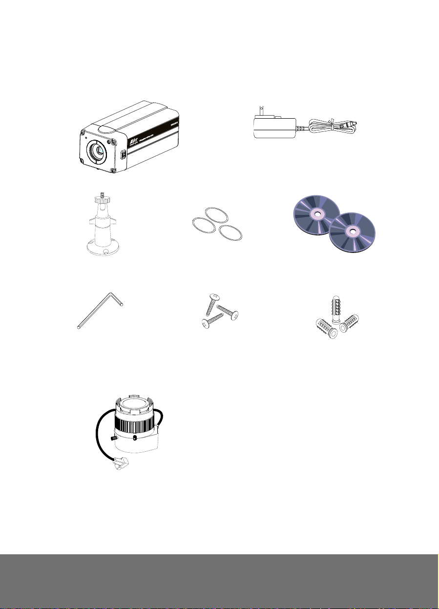
PPaacckkaaggee CCoonntteennttss
Make sure the following items are included in the package.
Power Adapter (12V, 2A)
* The power adapter will vary depending on the
standard power outlet of the country where it is
3 Screws
AVer SF2121H-R
Camera Stand
L-type Hex Wrench
3 Lens Ring Pad
sold.
Software & Manual CD
3 Plastic Anchor
OOppttiioonnaall AAcccceessssoorryy
CS-mount Lens
2

IIPP CCaammeerraa PPaarrttss
Front Panel
(1)
(2)
(1) Built-in MIC
(3)
(fig. 1.1)
(2) Lens
(3) Light Sensor
Rear Panel
(1) RJ45 Ethernet Port
(1)
(2)
(3)
(4)
(5)
(6)
(7)
(8)
(9)
(10)
(11)
(fig. 1.2)
Note: The reset button will set all the configuration settings back to factory default.
(2) DC 12V
(3) I/O Terminal Block
(4) Power LED Indicator
(5) SD card slot
(6) Video Out
(7) Audio Out
(8) Reset button
(9) Console
(10) MIC
(11) DIP switch
CS-Mount Lens
(1) Zoom controller
(2) Focus controller
(3) DC-Iris control cable
(1)
(2)
(3)
(fig. 1.3)
3
Seettttiinngg UUpp tthhee IIPP CCaammeerraa
S
This section provides useful tips on how to adjust the IP camera to meet your
needs.
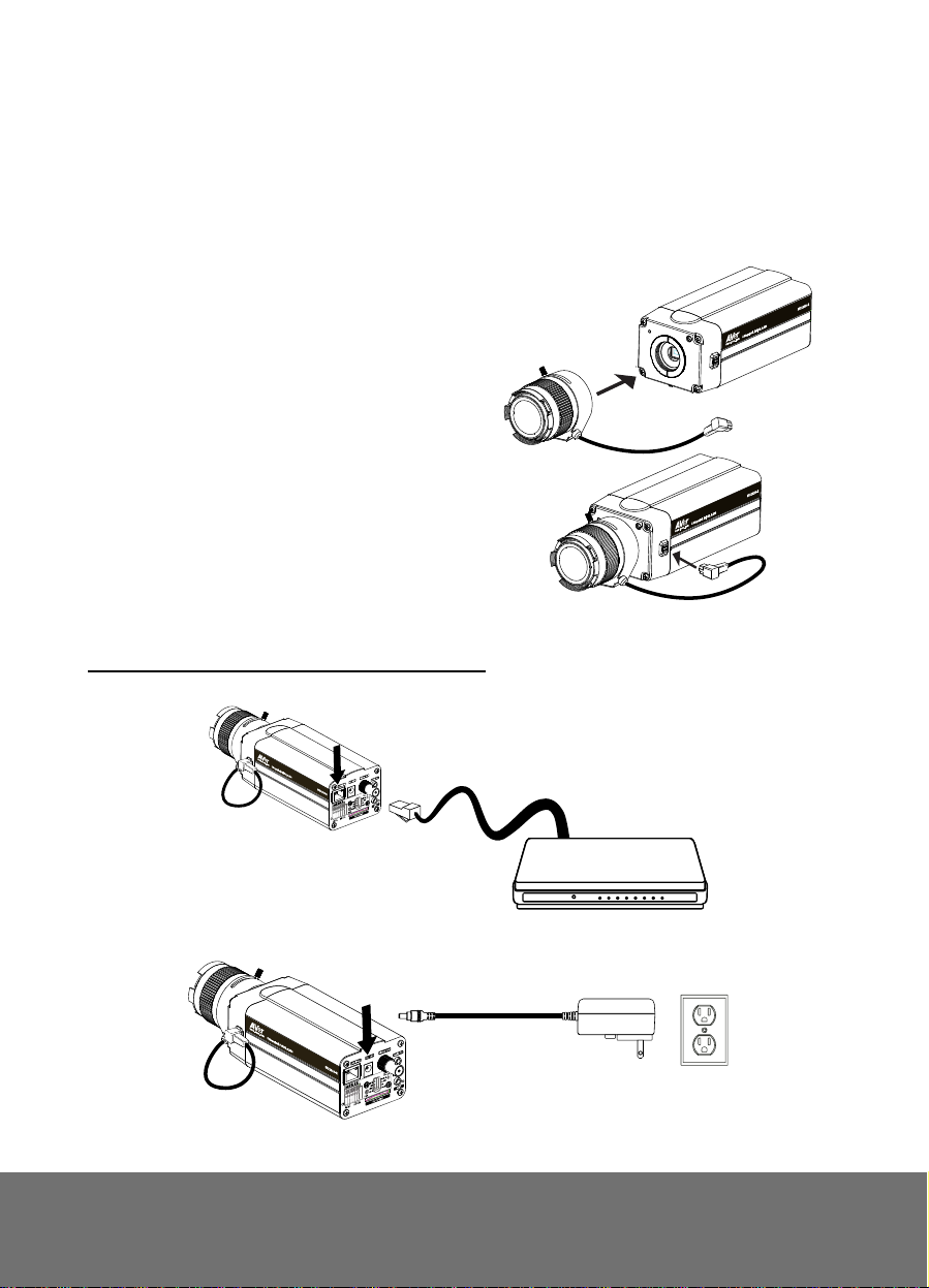
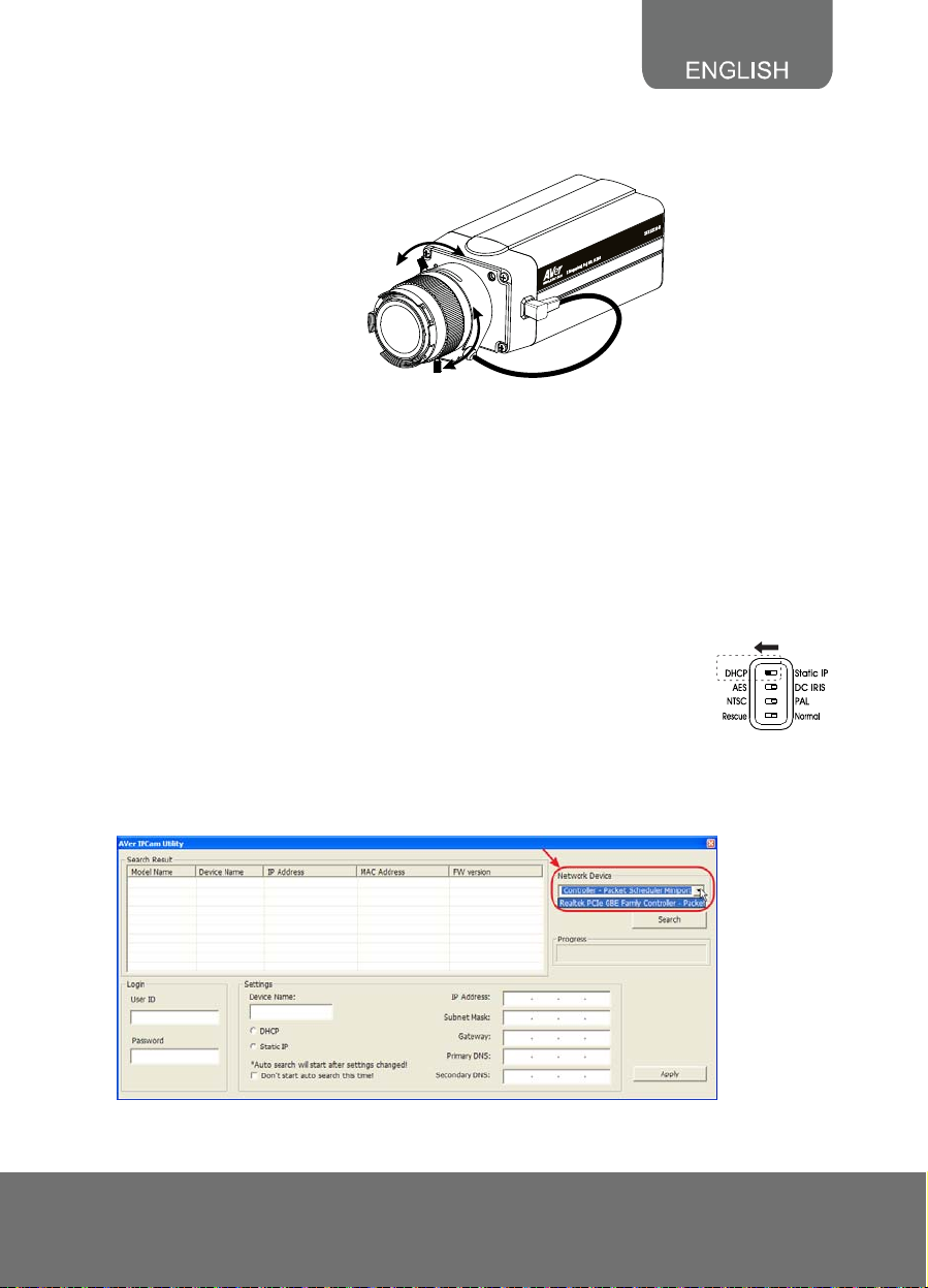
Connecting the Lens
1. Screw in the CS-mount lens clockwise
to the CS-mounting ring.
Make sure the lens adhesive cover is
removed when using it for the first time.
2. Connect the CS-mount lens cable to
the socket.
Deploying Network
Network Connection via Ethernet Switch
1. Connect the RJ45 cable from the Ethernet switch to LAN (PoE) port of SF2121H-R.
2. Connect the power adapter to DC12V port of SF2121H-R.
Power Adapter
Ethernet Switch
Wall Outlet
4
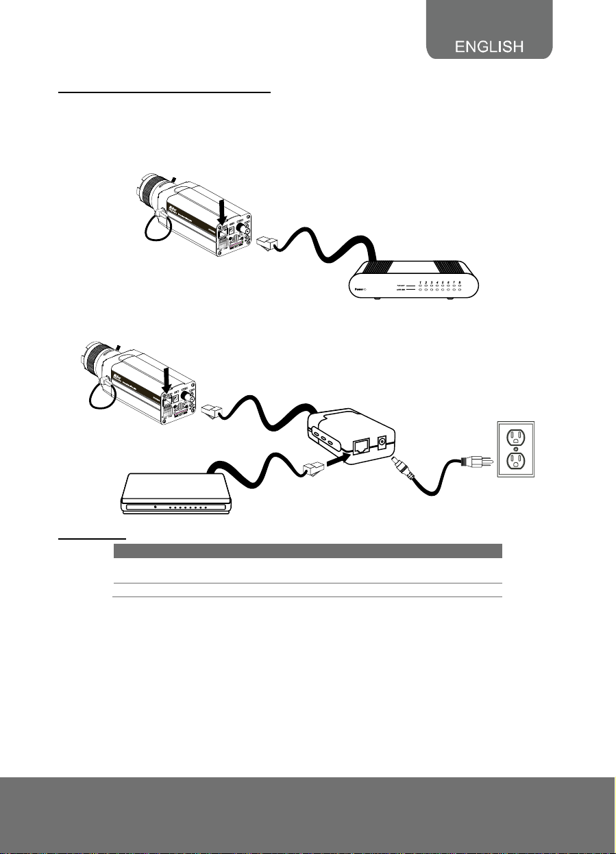
Power over Ethernet Connection
SF2121H-R is fully complied with PoE standard. It allows you to use PoE enabled switch or
PoE injector to transmit data and power thru single Ethernet cable.
PoE Enabled Switch Connection Diagram
PoE Switch
PoE Injector Connection Diagram
PoE Injector
Wall outlet
Power cable
Ethernet Switch
RJ45 LED
Blinking Green Connected to 100 Base-T mode and also
Steady Yellow Connected to the Internet.
LED Status
transmitting and receiving data.
5
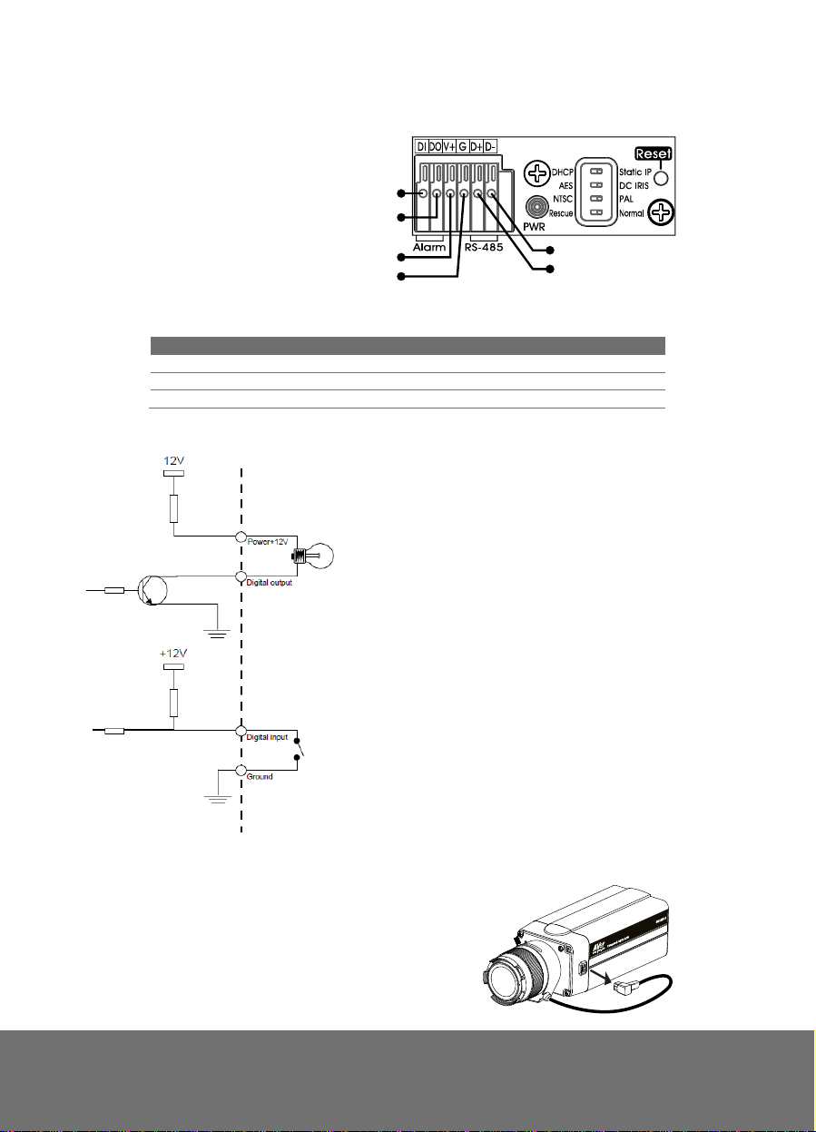
Connecting the External Devices to I/O Terminal Block
(1) Alarm Data In
(2) Alarm Data Out
support 200mA (3) Power 12V
(4) Ground
(5) RS-485 (+)
(6) RS-485 (-)
Power LED
LED Status
Steady Red Power on
Blinking Red Firmware update complete
No Light Power off
Internal Connection Diagram of DI/DO
(1)
(2)
(3)
(4)
(6)
(5)
Adjusting the CS-mount Ring
1. Unplug the CS-mount lens cable from
the socket.
6
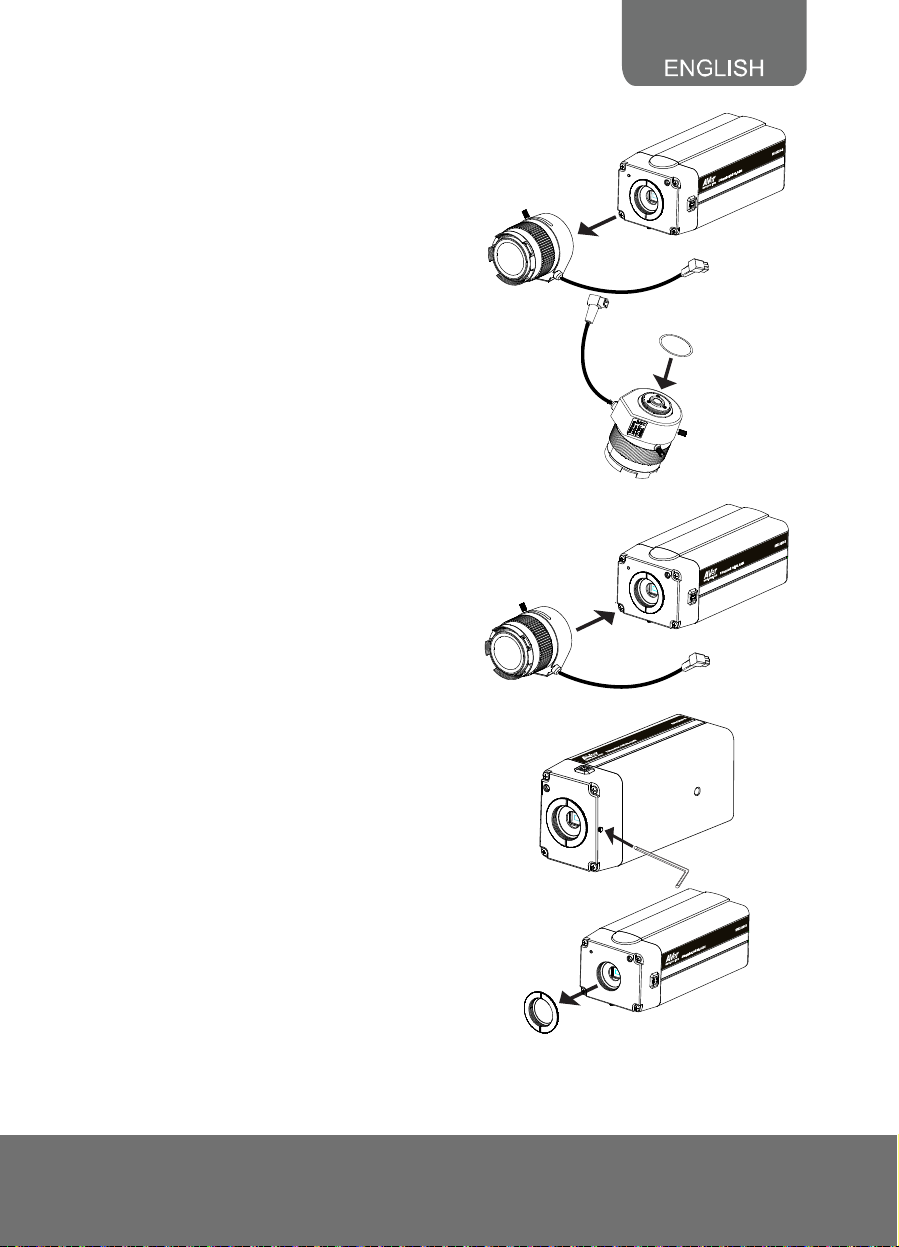
2. Unscrew the CS-mount lens
counterclockwise.
3. Place one lens ring pad.
4. Screw the CS-mount lens and connect
the CS-mount lens cable to the socket.
Check if the IP camera can display
proper image. If not, repeat step 3 and
4 to add the next ring.
If all the rings are used up and still the
IP camera cannot display proper
image. Remove all the rings and
continue to next step.
5. Using the L-type hex wrench loosen the
bolt underneath the IP camera.
6. Remove the CS-mount ring from the IP
camera.
7
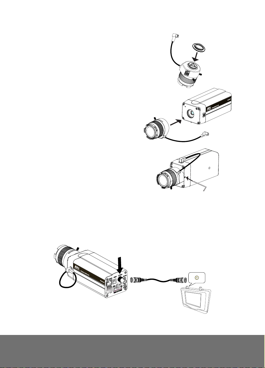
7. Screw the CS-mount ring to the CS-
mount lens.
8. Screw the CS-mount lens clockwise
back. Unscrew a little and plug the CSmount lens cable to the socket. Repeat
this till the IP camera display the image
properly.
9. Once the IP camera has detected the
image, use the L-type hex wrench
slightly secure bolt underneath the IP
camera.
Note: Do not fully tighten bolt
underneath the IP camera for it may
damage the CS-mount ring.
FFooccuussiinngg tthhee IIPP CCaammeerraa wwiitthh BBNNCC MMoonniittoorr
The IP camera is supported with BNC analog video out port which allows you to connect an
analog display devices such as an LCD BNC monitor for you to adjust the camera focus
and zoom.
1. Connect the LCD BNC monitor to the Video Out port of IP camera using a BNC cable.
VIDEO IN
BNC PORT
LCD BNC Monitor
8
2. Loosen up the focus and zoom control screws and adjust the focus and zoom range.
Tighten the focus and zoom screw once you are done adjusting.
Zoom Control
Focu s Con trol
Setting up the IP Camera over the Internet
Depending on your network connection, you can add the IP camera to the network in
DHCP or Non-DHCP server/router. Make sure the IP address of your computer and the IP
camera must be within the same LAN. In accessing the IP camera, you need to use IE
browser.
Setting up the IP Camera over the Internet
Using DHCP Server/Router Network
DHCP server/router network automatically assigns IP addresses to devices. You can use
the IPCam Utility software in the CD to search the IP camera in the network.
1. Make sure the DIP switch behind the IP camera is set to DHCP.
2. Install the AVer IPCam Utility software.
3. Run the IPCam Utility.
4. Select the pr oper network adapter and click [Search] to begin searching.
5. Select and double click the IP camera you want to access. If you want to change the
setting of the selected IP camera, enter the user ID, correct password, and change the
9
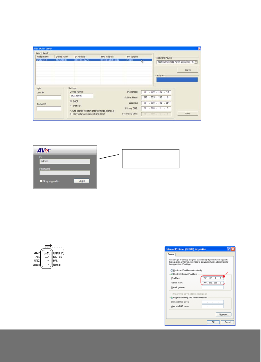
settings and then click [Apply]. This will change the setting and rescan the network
again.
The IE browser will open and direct you to IP camera login page. This requires
6.6.
IPViewer.ocx to run. If the IE ActiveX warning message appears, click to allow running
the add-on.
Using NON-DHCP Server/Router Network
In Non-DHCP server/router network, the static IP address must be assigned to the device
and each time when adding another IP camera in the network, the default IP address of the
current one must be changed to avoid conflict .
1. Make sure the DIP switch behind the IP camera is set to Static IP.
Default ID : admin
Password : admin
Default IP : http://192.168.1.168
2. Connect the co mputer to the network and set the IP
address with the same subnet prefix of 192.168.1.XXX.
The last decimal number should be set any from 1 to
255 except 168 and other IP addresses that are
already being assigned. Then set the Subnet Mask to
255.255.255.0.
To change the computer IP address, go to Control
10
 Loading...