

Page 1

AVer IP Camera
User Manual
1
Page 2

Table of Contents
Using the IP Camera Browser Interface ........................................ 3
Live View ................................................................................................ 3
System > General ................................................................................... 4
System > General > Maintenance........................................................... 4
To Upgrade the IP Camera Firmware ................................................ 5
System > General > Date & Time ........................................................... 6
System > General > System Log ............................................................ 7
System > User Management .................................................................. 7
System > User Management > Account .................................................. 7
To Create a User Account ................................................................. 7
To Delete or Edit a User Account....................................................... 8
System > User Management > Connection ............................................ 9
To Add Filter .................................................................................... 10
System > Network ................................................................ ................. 10
System > Network > Setting ................................................................. 10
System > Network > Server .................................................................. 12
System > Network > DDNS .................................................................. 12
System > Network > QoS ..................................................................... 13
System > Network > Others .................................................................. 14
System > Image .................................................................................... 15
System > Image > OSD ........................................................................ 15
System > Image > Preference .............................................................. 15
System > Image > Exposure ................................ ................................. 16
System > Image > Advanced ................................................................ 17
System > Image > Privacy Mask........................................................... 19
System > Video Stream ........................................................................ 19
Smart Stream ........................................................................................ 21
System > Audio ..................................................................................... 22
System > SD/microSD Card > Management ........................................ 22
System > SD/microSD Card > File Search ........................................... 23
Application > Motion Detection ............................................................. 24
To Set the Motion Detection ............................................................ 25
Application > ePTZ ............................................................................... 25
To Setup the ePTZ .......................................................................... 25
Event ..................................................................................................... 26
To Setup the Event .......................................................................... 27
Status Information ................................................................................. 29
2
Page 3
(4) (3)
(6)
(8)
(7)
(1)
(2)
(5)
(10) (15)(9) (11) (12)(13)(14)
Name
Function
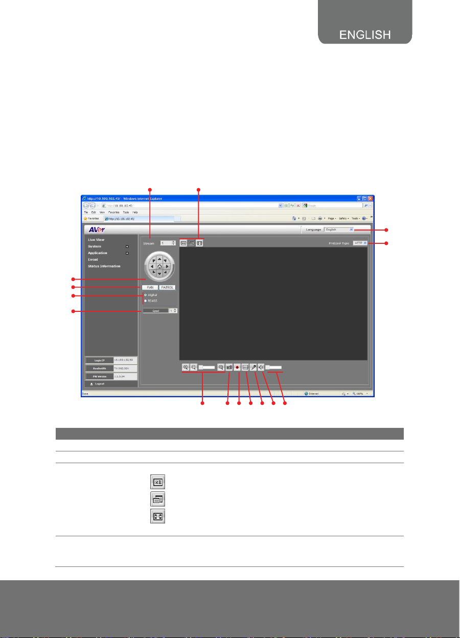
(1) Language
Select the browser interface language.
(2) Protocol Type
Select the protocol for the live view video stream.
(3) Video screen
Change the video screen display.
Display the actual video pixel size.
Display the video screen in compact size.
Display the video on the entire screen. Press ESC to exit full
screen mode.
(4) Stream
Switch to view the video stream type. The IP camera can send
multiple video streams of up to 3 types. To change the video stream
setting, go to System > Video Stream.
Usin g the IP Ca mera B r owser Inter face
The admin have the full access to the IP camera browser interface. The menu on the left,
you can expand and navigate to access all the features.
Live View
In the Live View page, all three user levels can view and change the language setting, the
IP camera video stream setting, use the digital or RS-485 Pan and Patrol control, capture
screen shot, record video, turn on/off 2-way talk, mic and volume, and adjust the zoom and
volume level.
3
Page 4
Name
Function
(5) Direction buttons
- Use to move the position of the view point while in zoom mode.
- Use to control the position of the RS-485 pan tilt device
(6) Pan & Patrol
button
Pan - automatically move the view point from left to right when in
zoom in mode.
Patrol - automatically move the view point around the preset
locations in Application > Patrol.
(7) Digital /RS-485
- Select Digital to control the IP camera ePTZ operation. This
allows you to closely view the target area without having to
physically move the IP camera. The image will be zoomed in and
you can use the direction control to pan the zoomed image.
- Select RS-485 to control the PTZ driver or scanner via RS-485
connection to I/O terminal block. The IP camera is mounted on an
RS-485 pan tilt device.
(8) Speed control
Set the speed when panning, tilting, or zooming.
(9) Zoom control
Reset zoom level.
Increase zoom level.
Decrease zoom level.
(10) Capture
Capture and save the image on the screen in *.bmp format.
(11) Record
Start/stop audio and video recording. The recorded video will be
saved in *.mp4 format.
(12) 2-way talk
Enable/disable mic from IP camera browser side.
(13) Mic
Enable/disable mic from the IP camera side.
(14) Sound
Enable/disable audio from the IP camera side.
(15) Volume bar
Adjust the volume.
System > General
In this section, only admin level is authorized to configure the IP camera general settings.
There are 3 tabs in General settings: Maintenance, Date & Time, and System Log.
You can view the significant occurrence in the IP camera such as
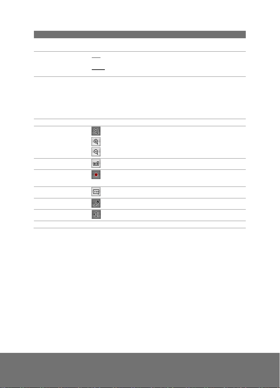
System > General > Maintenance
In the Maintenance tab, the admin can easily backup and restore the IP camera setting,
reboot the IP camera, reset all the settings to factory default, and upgrade the IP camera
firmware.
4
Page 5
(2)
(3)
(4)
(5)
(6)
(1)
Name
Function
(1) Reboot
Restart the IP camera.
(2) Reset
Set all the configuration settings back to default except the user
management and network settings.
(3) Factory Default
Set all the configuration settings back to factory default.
(4) Export Settings
Backup all the configuration settings.
(5) Import Settings
Restore or replace the current settings with the backup file.
(6) Firmware Upgrade
Upgrade the firmware to the latest version.
To Upgrade the IP Camera
Firmware
1. Download the file from
our website and save it in
your computer hard disk.
2. Click Browse. Locate and
select the file and click
Open.
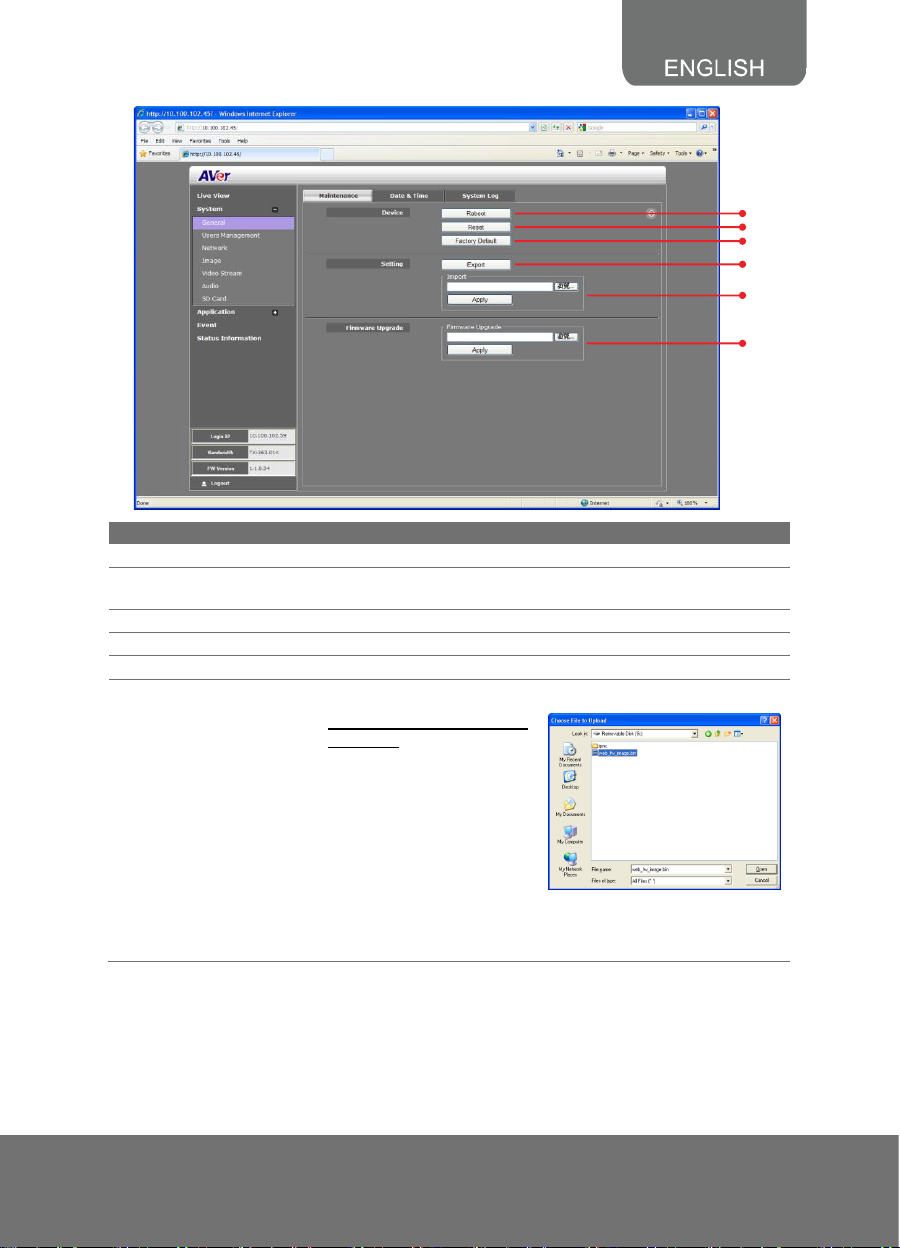
3. Click Apply. Wait till you see the massage “Firmware
Upgrade OK!!”. You may now click the IE browser refresh
button or press F5. The login page will appear.
5
Page 6
Name
Function
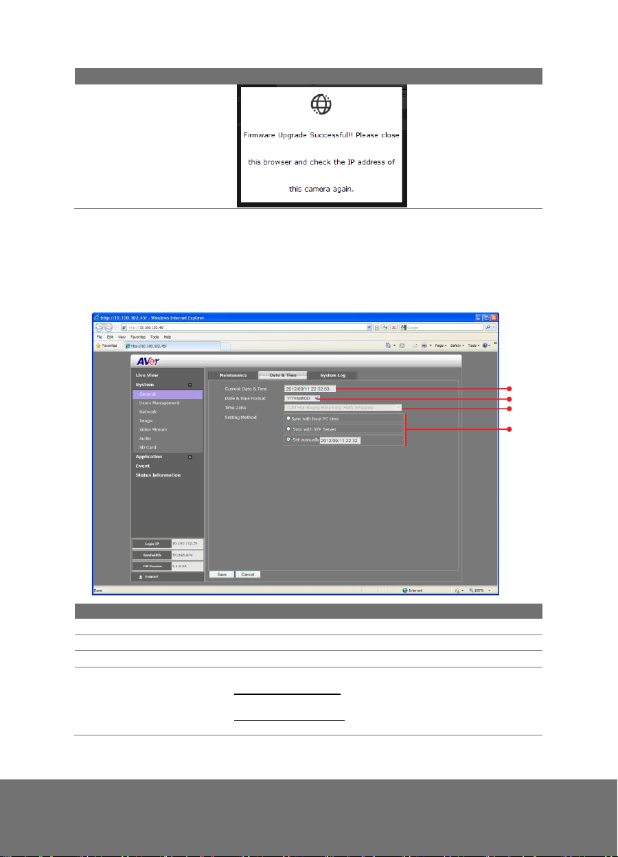
System > General > Date & Time
(2)
(1)
(3)
(4)
Name
Function
(1) Current Date & Time
Display the current date and time setting.
(2) Date Format
Select the date display format.
(3) Time Zone
Set the local time zone.
(4) Setting Method
Select the date & time setting method.
Sync with current PC – obtain the date and time setting on
the current login computer.
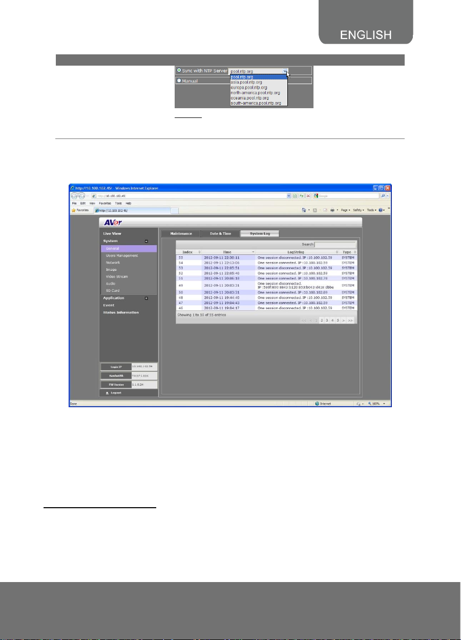
Sync with NTP Server – obtain the date and time setting from
NTP server. In the drop-down list, select the NTP host name.
In the Date & Time tab, admin can manually set the date and time setting or synchronize it
with the Internet time server or the computer date and time setting. This is used to record
the time whenever there is a significant occurrence listed in system log and is also used in
event scheduling. After completing the setting, click Save to apply the new setting and
Cancel to keep the old setting.
6
Page 7
Name
Function
Manual – manually set the date and time. Click Now to set
the date base on the computer time setting and Done to close
the date and time interface.
System > General > System Log
In the System Log, admin can view and search the significant event occurred in the IP
camera.
System > User Management
In User Management, only admin level is authorized to create, delete, and edit account to
connect to the IP camera and configure the client connection setting. There are 2 tabs in
User Management setting: Account and Connection.
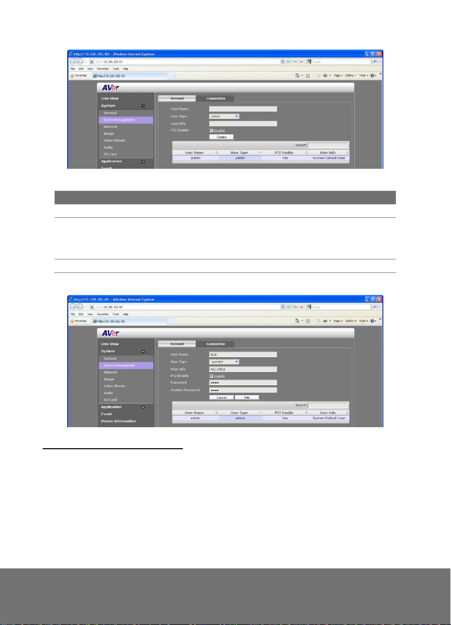
System > User Management > Account
In Account tab, admin can create, delete and set the access level of the user account.
To Create a User Account
1. Click System > User Management > Account tab.
2. Enter the User Name, select the User Type, enter the User Info and click Create.
7
Page 8
User Type
Access rights
Admin
Can access all the configuration pages
Operator
Can preview live image, modify and adjust certain settings except in
System > General, User Management, and Network; and
SD/microSD Card > Management. As for the I/O Control, admin could
enable/disable allowing operator to access it.
Viewer
Can only access the preview and status information pages.
3. Enter the same password in Password and Confirm Password text box. Then click Add.
To Delete or Edit a User Account
Select the user account you want to delete or edit in User Management > Account tab.
- Click Cancel to void the operation.
- Click Modify to apply the new changes. Make sure to edit the account before clicking
the Modify button.
- Click Remove to delete the account.
8
Page 9
(2)
(1)
(4)
(6)
(3)
(5)
Name
Function
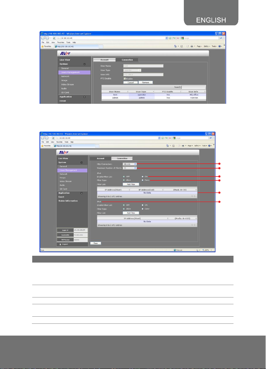
(1) Http Connection
Select the connection type. For higher security data
transmission level, select http & https or http only. This
authenticate and encrypted the data over the SSL(Secure
Socket Layer).
(2) Maximum Number of
Clients
Select the max number of user to simultaneously access the
IP camera.
(3) Enable Filter List
Select to turn the IP address filtering on/off.
(4) Filter Type
Select to allow/deny the IP address in the filter list to access
the IP camera.
(5) Filter List
Create and display the filtered IP address.
System > User Management > Connection
In Connection tab, admin can set the total number of user to access the IP camera, and
filter the IP address to allow or deny accessing the IP camera.
9
Page 10

Name
Function
To Add Filter
1. Click Add Filter in User Management > Connection tab.
2. In Rule drop down list, select from the 3 types of rules:
Single, Network and Range.
Single – add an IP address
Network – assign a network address and the
corresponding subnet mask to be filtered.
Range – assign a range of IP address to be filtered.
3. Save to add the created data in the filter list or Cancel to
void the operation and exit.
(6) IPv6 Filter
Please follow the IPv4 filter rules to set up IPv6 filter.
System > Network
In this section, only admin level is authorized to set up the Network settings.
System > Network > Setting
In Setting tab, you can configure the type of network connection for IP camera and assign
name for the IP camera. Depending on the network connection, IP camera can be
accessed from the computer within the same local area network (LAN) or anywhere with
Internet connection. After completing the setting, click Save to apply the new setting and
Cancel to keep the old setting.
10
Page 11

*(2)
(3)
(4)
(1)
Name
Function
(1) Device Name
Assign name for the IP camera.
(2) Network HW Switch
Enable/disable to use the IP camera dip switch network setting.
If this is enabled, make sure the dip switch behind the IP
camera is set properly.
* ( Available for FX series and SF2121H-R Box type only )
(3) Network Type
Select the type of IP camera Network connection.
DHCP – select this option to automatically obtain an IP address
from the DHCP server, whenever the IP camera is connected to
the network. You can use the IP camera UPnP Discovery
software in the CD to easily setup the IP camera network.
Static IP – select this option to manually assign a fix IP address
to the IP camera.
PPPoE – select this option to access the IP camera anywhere
with Internet connection. To use this option, this requires an
account provided by the ISP. Set this setting while connected to
the LAN and click save. Connect the IP camera directly to DSL
or cable modem.
11
Page 12

Name
Function
(4) IPv6 Settings
Enable IPv6 support
Select “Manually set the IP address” to specify IP address
manually.
System > Network > Server
In Server tab, you can configure the Email, FTP, and NAS setting. It is necessary to
configure the server settings so that IP camera can perform the task in the Event setting
when a trigger is activated. You can configure either one or all of it. After completing the
setting, click Save to apply the new setting and Cancel to keep the old setting.
System > Network > DDNS
In DDNS tab, you can configure the dynamic domain name service setting. DDNS is a
service that provides fixed host and domain name for the IP camera with dynamic IP
address. It automatically updates the new IP address to the dynamic server of the domain
name.
12
Page 13

To use this feature, you need to register a domain name at http://dyn.com/dns/ . Enter the
DDNS domain name, user, password and enable DDNS enable check box. After
completing the setting, click Save to apply the new setting and Cancel to keep the old
setting.
System > Network > QoS
In QoS tab, you can configure the Quality of Service setting. Enabling the QoS allows you
to set the parameter and prioritize the IP camera to provide stable streaming performance
at a certain level in a traffic network.
13
Page 14

System > Network > Others
In Others tab, you can configure the enable/disable the UPnP setting. If your router does
not support UPnP function, you can enable the UPnP forwarding and set the port mapping.
14
Page 15

(1)
(4)
(2)
(5)
(3)
Name
Function
(1) Time Stamp
Select the location of the Time Stamp. Click the checkbox to
enable/disable display the date and time stamp.
(2) Customize Title
Select the location of the Text Title. Click the checkbox to
enable/disable display the text title.
(3) Title Text
Enter the title text, e.g. AVer.
(4) Logo
Select the location of the logo image file. Click the checkbox to
enable/disable display the logo.
(5) Customize
Logo
Upload your company logo. The maximum size is 64 x 64 pixels.
System > Image
Both admin and operator levels can adjust the Image setting. There are 5 tabs: OSD,
Preference, Exposure, Advanced, and Privacy Mask.
System > Image > OSD
In OSD tab, you can enable/disable overlaying time stamp, text title and add logo. After
completing the setting, click Save to apply the new setting and Cancel to keep the old
setting.
System > Image > Preference
In Preference tab, you can tune the IP camera white balance, display color or black & white,
set the flicker frequency, change the video orientation, and adjust the brightness and
contrast. After completing the setting, click Save to apply the new setting and Cancel to
keep the old setting.
15
Page 16

(2)
(1)
System > Image > Exposure
In Exposure tab, you can set the exposure zone, exposure mode, and calibrate the DC Iris.
After completing the setting, click Save to apply the new setting and Cancel to keep the old
setting.
16
Page 17

Name
Function
(1) Exposure Area
Select the exposure area choices to define the light distribution and
bring out more details.
Entire screen - measure the entire screen to adjust the exposure.
Customize - measure the exposure to where the adjustable and
movable frame on the screen is located. Move the spot to dark
zone to adjust the light condition.
Backlight compensation - measure the exposure at the center of
the screen.
(2) Exposure Mode
Select to automatically or manually adjust the exposure.
Auto - adjust exposure level from -2.0 to +2.0
Manual - adjust max shutter and gain control
(5)
(1)
(2)
(3)
(4)
System > Image > Advanced
In Advanced tab, you can configure the Wide Dynamic Range, Denoise, IR-Cut Filter, and
B/W image at night. After completing the setting, click Save to apply the new setting and
Cancel to keep the old setting.
17
Page 18

Name
Function
(1) Wide Dynamic
Range
WDR effectively balances the video image on the screen in both
bright and dark areas making it possible to see clear details. You
can choose from 3 levels depending on your choice or disable
WDR.
(2) Denoise
Select Disable/2D/3D to reduce the excessive noise on the video
image.
Auto - automatically switch between 2D and 3D. Use Sensitivity
option to adjust sensitive level. The higher level means the
higher sensitivity.
(3) IR-cut Filter
The IR cut filter is a mechanism that prevents the infrared light
from hitting the sensor. During day time the IR light has an
interfering effect on the image quality of the camera, which leads
to corruption of color and contrast as well as blurring. At night
time, the infrared light is used to achieve more detailed images in
the dark or with low ambient light.
Auto – automatically switch on/off the IR cut filter. It uses the light
sensor in front of the camera to determine the level of ambient
light.
Day Mode – switch on the IR cut filter at all time to prevent the IR
light from hitting the sensor so that the color will not be corrupted.
Night Mode – switch off the IR cut filter at all time to let the sensor
receives the IR light which could help improve low light sensitivity.
Schedule – specify the time on when to switch off the IR cut filter
to night mode. The time format is hh:mm and in 24-hour clock
time.
(4) B/W image at night
Select to enable/disable switching to B/W during night mode.
(5) Night mode priority
Select the one you want to prioritize during night mode image
quality or frame rate.
18
Page 19

System > Image > Privacy Mask
In Privacy Mask tab, you can enable 3 privacy masks. Simply adjust the size and position
the mask on the area you want to conceal. The viewer will not be able to see the masked
area. It will cover the video screen with black frame.
System > Video Stream
Both admin and operator levels can configure the Video Stream. After configuring the video
stream setting, click Save to apply the new setting and Cancel to keep the old setting.
19
Page 20

*(1)
(2)
(3)
(4)
(5)
(6)
(7)
Name
Function
(1) Sensor Mode
Select sensor input resolution from either Normal or Wide Angle.
* ( Available for 3M pixel or above model )
(2) Stream Type
Select to transmit single or simultaneous multiple streams of 2 or
3 videos.
(3) Stream
Select the streaming source.
(4) Region of Interest
Select the cropping size of video.
(5) Output Resolution
Select the video size.
(6) Frame Rate
Select frame rate per second of video
(7) Code Type
Select the type of video compression codec. The supported
codec is H.264, MPEG4, and MJPEG. On each stream, adjust
rate control and video quality setting.
20
Page 21

Name
Function
VBR (Variable Bit Rate) by default use this setting if there is a
need to maintain the image quality whenever there is lot of
activities on the scene or no motion. This setting keeps the video
stream constant as possible which increases the bandwidth
requirement when there is high motion and decreases when
there is no motion. The bandwidth must be able to accommodate
high throughputs.
CBR (Constant Bit Rate) use this setting if there is bandwidth
concern. This setting is restricted to keep the bit rate setting. This
could affect the image quality and frame rate if there is high
activity that result in a bit rate that is higher than the set bit rate.
(1)
(2)
Name
Function
(1) Stream
Select the streaming source. This option is only applied to
H.264.
(2) Quality
High - video quality of selected area is better than that of
un-selected area.
Low - video quality of selected area is worse than that of
un-selected area
Smart Stream
21
Page 22

(4)
(1)
(2)
(3)
Name
Function
(1) Audio
Select to enable/disable the IP camera built-in mic and mic port.
(2) Internal/External
MIC gain
Select to boost up the internal/external mic gain or set to
normal.
(3) Audio Codec
Select the audio protocol, algorithm, and audio bit rate.
G.711 – uses Pulse code modulation (PCM) of voice.
G.726 – uses 40, 32, 24, 16 kbit/s adaptive differential pulse
code modulation (ADPCM)
AAC – uses AAC codec
(4) Alarm Audio
Select to choose from 2 types of alarms sound or customer
alarm to use the uploaded alarm sound. The supported sound
format are in *.wav (PCM 8KHz/16bit Mono, 10 seconds).
System > Audio
Both admin and operator levels can configure the IP camera audio setting. After configuring
the Audio setting, click Save to apply the new setting and Cancel to keep the old setting.
System > SD/microSD Card > Management
Both admin and operator levels can manage the SD/microSD Card local storage. After
managing the SD/microSD Card setting, click Save to apply the new setting and Cancel to
keep the old setting. We recommend formatting the SD/microSD card when using it for the
first time.
22
Page 23

(5)
(2)
(1)
(3)
(4)
Name
Function
(1) SD/microSD Card
Info
Shows the SD/microSD card details. No details will appear if
SD/microSD Card is not inserted.
(2) Cycle Storage
Enable/disable cycle recording. The old file in the SD/microSD
card will be overwritten with the latest one when it has reached
the maximum capacity.
(3) Automatic Cleanup
Enable/disable automatic clear the data in SD/microSD card.
The file will be deleted when it reached the number of days set
in Delete data after [xx] days.
(4) Delete data after
Enter the number of days you wish to retain a file.
(5) Format
Click Format to delete all the data in the SD/microSD card.
System > SD/microSD Card > File Search
Use this to search the captured image in the SD/microSD card.
23
Page 24

Application > Motion Detection
Both admin and operator levels can specify up to 3 areas on the screen to monitor the
motion. In the motion detection page, the frame will blink when the motion detected has
reached the percentage threshold setting. This feature can be utilized to trigger a response
in Event setting.
24
Page 25

To Set the Motion Detection
1. Click Application > Motion Detection.
2. Enable the region check box to create a motion detection frame.
3. Move and adjust the frame to the area you want to detect the motion.
4. Adjust the sensitivity and percentage. Sensitivity detects the motion on the screen and
assesses the changes in pixel thru percentage. The motion detection will activate when
the Monitor level reaches the defined percentage.
5. Click Save to apply the new setting and Cancel to keep the old setting.
Application > ePTZ
Both admin and operator levels can customize the ePTZ setting. In this section, you can set
the patrol target area, patrol sequence and dwelling time.
To Setup the ePTZ
1. Click Application > ePTZ
2. Use the direction buttons and zoom button to locate the patrol target area. Press to
view the full image and reset the zoom level.
3. Type a name for the patrol shooting area e.g. UpperLeft in the Name text box and press
[Add]. The preset target area will be listed in the User Preset Locations. Click to
delete the preset target area and to show the preset target area. Repeat step 2 and
25
Page 26

3 to add more preset locations.
4. Select the preset target area in the list and press to create the patrol sequence. The
selected present target area will be listed in the Patrol Locations.
5. Set the dwelling time for how long you want to stay in the preset target area. Doubleclick and enter the time. Then click OK or press enter to apply the changes.
6. Click to delete the selected preset location in the Portal Locations list and to
arrange the patrol order.
7. Click Save to implement the preset patrol setting.
Event
Both admin and operator levels can configure the Event setting. In this section, the IP
camera can be configured to perform an action when an event is triggered at the specified
time.
26
Page 27

To Setup the Event
1. Click Event.
2. On the time table, click-drag to select from what time to what time to specify the period
of the event.
3. Type a name for the Event setting. One word only and no special character.
4. Select the event color setting.
5. Set the schedule. You can edit the time and choose the days to apply the same time
setting.
6. Enable the type of selection for the IP camera to trigger.
27
Page 28

- Alarm Interval
This triggers the IP camera based on the set time.
- Motion Detection Region 1/2/3
This triggers the IP camera when a motion is detected on the motion detection region.
- Digital Input
This triggers the IP camera when the external digital input device or sensor is
activated.
- SD Card / microSD Card
This triggers the IP camera when the SD/microSD card is removed.
- Network
This triggers the IP camera when the Internet connection got disconnected.
7. Select the type of response for the IP camera to perform when a trigger is activated. Set
the duration. Choose digital output to send recorded video or still image, or Alarm Audio
to sound the alarm. Then select the type of server/media to where to send the file. To
configure the FTP and NAS setting, go to System > Network > Server tab.
Snapshot and System log support sending the file thru Mail, and storing in FTP, NAS
or SD/microSD card. You can enable multiple options to send and save the captured
image.
8. Video Clip supports storing in FTP, NAS or SD/microSD card. You can only select one
storage option to save the video file. For better performance, we recommend setting the
video stream is default value. Click OK to add the event setting, Delete to remove, and
Cancel to void and close the event setting.
28
Page 29

Status Information
Show the information about the device and network setting.
29
 Loading...