

Page 1

SF2111H IP Camera Series
SF2111H-R/SF2111H-BR
SF2111H-DR/SF2111H-DVR
Quick User Guide
Page 2

Table of Contents
I. Camera Introduction .................................................................................................... 1
1. Box Type IP Camera (SF2111H-R) ..................................................................... 1
1.1 Package Contents .......................................................................................... 1
1.2 Hardware Installation ..................................................................................... 2
1.3 Factory Default ............................................................................................... 3
2. Bullet Type IP Camera (SF2111H-BR) ................................................................ 4
2.1 Package Contents .......................................................................................... 4
2.2 Hardware Installation ..................................................................................... 5
2.3 Factory Default ............................................................................................... 6
3. Dome Type IP Camera ........................................................................................ 7
3.1 Package Contents .......................................................................................... 7
3.1.1 SF2111H-DR ............................................................................................... 7
3.1.2 SF2111H-DVR ............................................................................................. 7
3.2 Hardware Installation ..................................................................................... 9
3.2.1 SF2111H-DR ............................................................................................... 9
3.2.2 SF2111H-DVR ........................................................................................... 11
3.3 Factory Default ............................................................................................. 15
3.3.1 SF2111H-DR ............................................................................................. 15
3.3.2 SF2111H-DVR ........................................................................................... 16
4. SD card Compatibility List.................................................................................. 17
II. Monitor Setting ........................................................................................................... 18
III. IP Assignment ............................................................................................................ 19
Finding IP Camera by using “NXU Lite recording software” .......................................... 19
Finding IP Camera by using “IP installer” ...................................................................... 22
Using DHCP Server/Router Network ............................................................................ 24
Using NON-DHCP Server/Router Network ................................................................... 25
Page 3

IV. Connecting the IP Camera ......................................................................................... 28
COPYRIGHT ...................................................................................................................... 29
NOTICE .............................................................................................................................. 29
WARNING .......................................................................................................................... 29
Limited Warranty .............................................................................................................. 30
Governing Law and Your Rights ..................................................................................... 31
Page 4

Page 5
Before Installation
Before installation, please be sure to read this quick installation guide and user’s manual carefully to
complete the installation.
I. Camera Introduction
The following section introduces package contents, hardware installation, factory default reset, and SD
card Compatibility List of each type camera.
1. Box Type IP Camera (SF2111H-R)
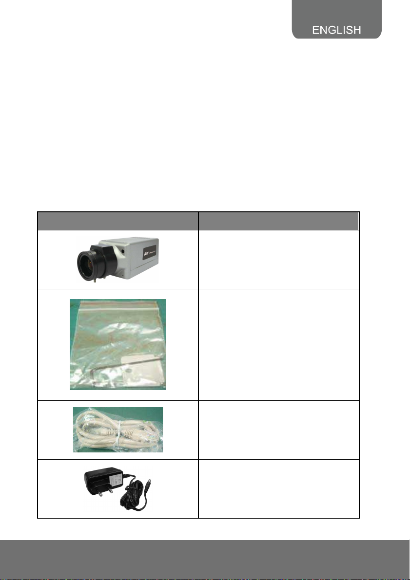
1.1 Package Contents
Item Descriptions
1. SF2111H-R
2. Accessory pack
3. Ethernet cable
4. Power Adapter (DC12V/1A)
(Optional)
1
Page 6
Item Descriptions
5. CD (User’s Manual and Quick Guide
included)
**If any of the above items are missing, please contact your dealer immediately.
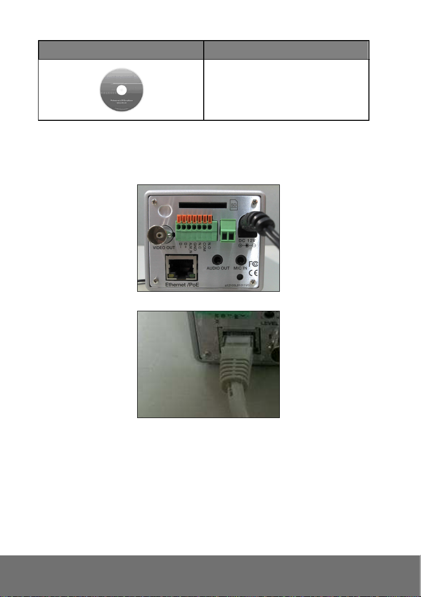
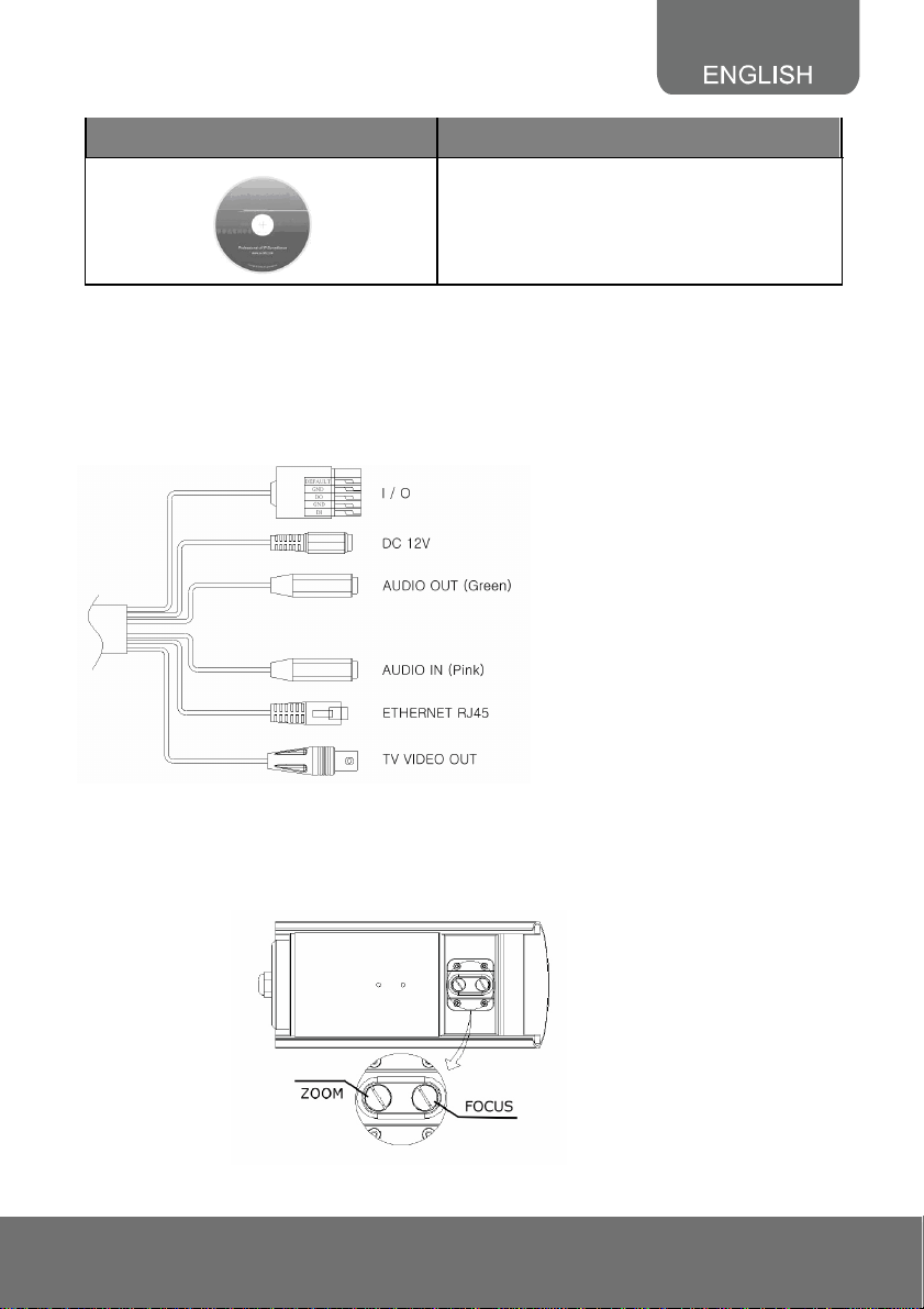
1.2 Hardware Installation
1. Connect power adapter or use PoE to eliminate the use of power cable.
2. Connect IP camera to PC or network with Ethernet cable.
2
Page 7
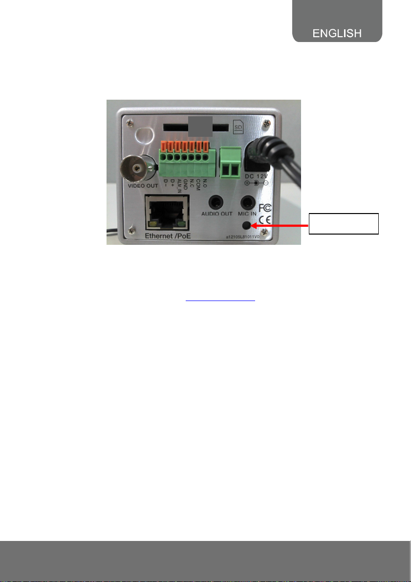
1.3 Factory Default
1. To recover the default IP address and password, please follow the following steps.
2. Remove power, press and hold the button in the back of IP camera.
Reset button
3. Power on the IP camera. Don’t release the button during the system booting.
4. It will take around 30 seconds to boot the camera.
5. Release the button when camera finishes proceed.
6. Re-login the camera using the default IP (http://192.168.1.200) or DHCP, and user name (admin),
password (admin).
3
Page 8
2. Bullet Type IP Camera (SF2111H-BR)
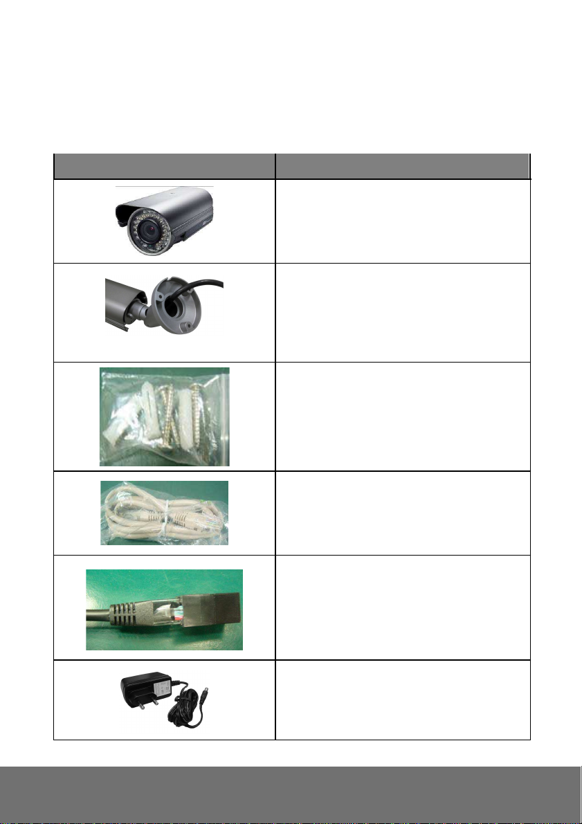
2.1 Package Contents
Item Descriptions
1. SF2111H-BR
2. Stand (The stand is well assembled while
shipped out)
3. Accessory pack
4. Ethernet cable
5. RJ45 socket
6. Power Adapter(DC 12V /1A)(Optional)
4
Page 9
Item Descriptions
**If any of the above items are missing, please contact your dealer immediately.
7. CD (User’s Manual and Quick Guide
included)
2.2 Hardware Installation
1. Connect a power adapter and IP camera to PC or local network.
2. The SF2111H-BR is equipped with an external vari-focal lens controller. Please adjust
“ZOOM” and “FOCUS” as following picture until the image gets clear.
5
Page 10
3. I/O Control Instruction
I/O terminal connector – used in application, for e.g., motion detection, event triggering, alarm
notifications. It provides the interface to:
Digital Input (GND+Alarm) : An alarm input for connecting devices that can toggle between
an open and closed circuit, for
1. GND (Ground) : Initial state is LOW
2. Alarm : Max. 50mA, DC 5V
Example: PIRs, door/window contacts, glass break detectors, etc. When a signal is
received the state changes and the input becomes active.
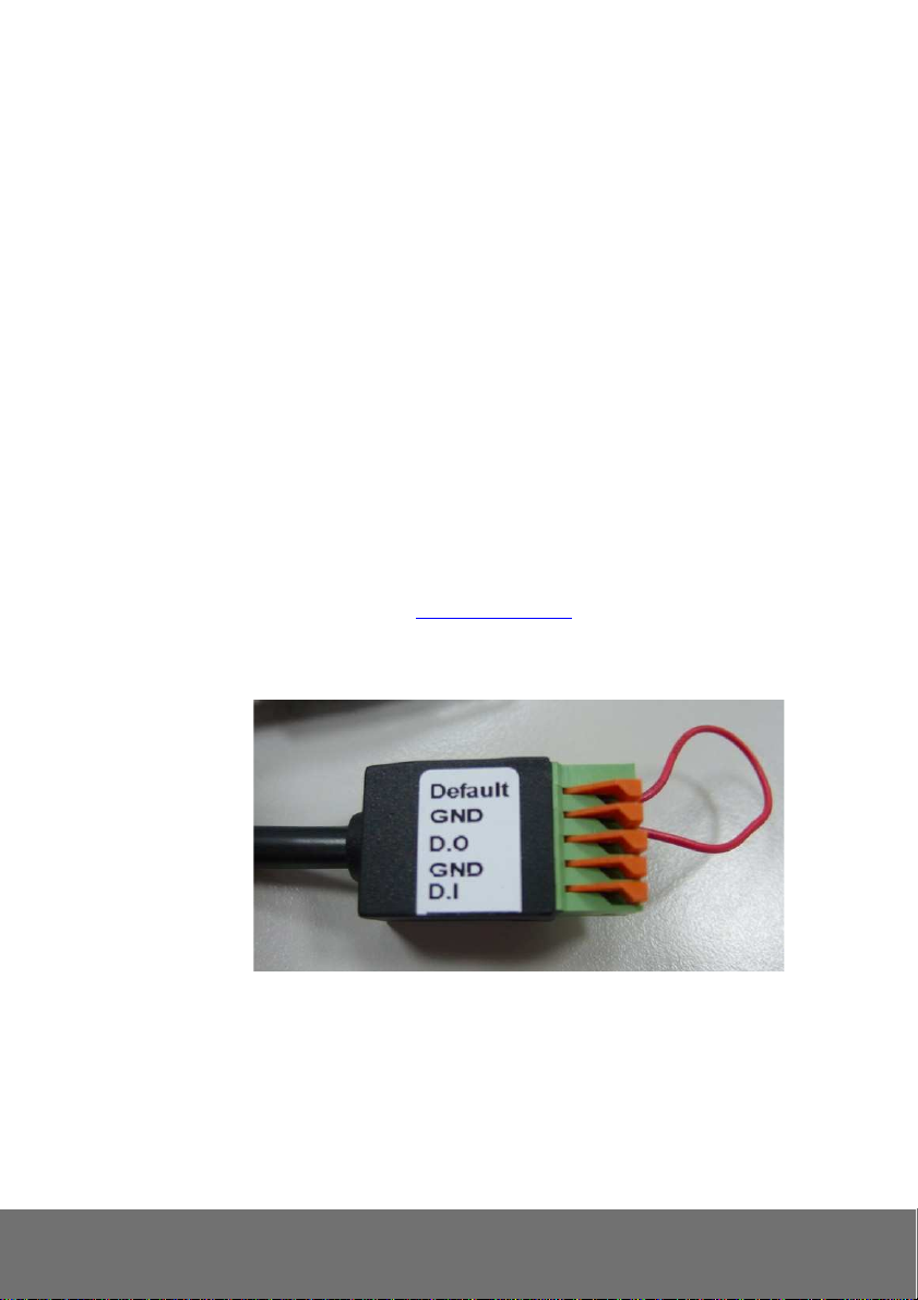
2.3 Factory Default
1. Remove the Ethernet cable and power adapter.
2. Take an electronic wire, plug one side of the wire into “Default” and the other side into “GND” on
the terminal block as the photo below.
3. Connect power again and connect Ethernet cable after the camera finishes rebooting..
4. Remove the wire. When camera starts again, please remove the pink default cable and plug
Ethernet cable for new setting.
5. Release the button when camera finishes proceed.
6. Re-login the camera using the default IP (http://192.168.1.200) or DHCP, and user name (admin),
password (admin).
.
6
Page 11
3. Dome Type IP Camera
3.1 Package Contents
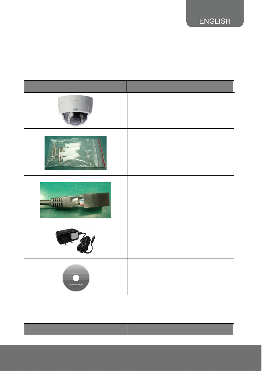
3.1.1 SF2111H-DR
Item Descriptions
1. SF2111H-DR
2. Accessory pack
3. RJ45 socket
4. Power Adaptor (DC 12V /1A) (Optional)
5. CD (User’s Manual and Quick Guide
included)
**If any of the above items are missing, please contact your dealer immediately.
3.1.2 SF2111H-DVR
Item Descriptions
7
Page 12

s Manual and Quick Guide
1. SF2111H-DVR
2. Accessory pack
3. RJ45 socket
4. Power Adaptor(DC 12V/1A)
(Optional)
5. CD (User’
included)
**If any of the above items are missing, please contact your dealer immediately.
8
Page 13

3.2 Hardware Installation
3.2.1 SF2111H-DR
1. Connect a power adapter and IP camera to PC or local network.
2. 3-Axis Gimbals Adjustments
Pan: 172°
Rotation: 180
Tilt: 30°~90°
°
Once the users open the case, the gimbals adjustment offers the convenience method to install on
the wall. The pan, tilt, and rotation are provided in this model. The users can adjust the
gimbals with Pan 172 degrees, tilt 30~90 degrees, and rotation 180 degrees respectively.
9
Page 14

3. Installation steps
(1) Use screws to lock the
bottom of camera to the
ceiling or the wall.
(2) Use 3-Axis to adjust the lens
angle.
(4) Tighten the screw on the
cover to fix it.
I/O Control Instruction
I/O terminal connector – used in application, for e.g., motion detection, event triggering, alarm
notifications. It provides the interface to:
Digital Input (GND+Alarm) : An alarm input for connecting devices that can toggle between an
open and closed circuit, for
1. GND (Ground) : Initial state is LOW
2. Alarm : Max. 50mA, DC 5V
Example: PIRs, door/window contacts, glass break detectors, etc. When a signal is
received the state changes and the input becomes active.
(3) Close the dome cover.
10
Page 15
3.2.2 SF2111H-DVR
1. Remove the dome cover, and you will see the structure as below.
G
DO
DI
G
Line out
MIC In
G
Video
microSD
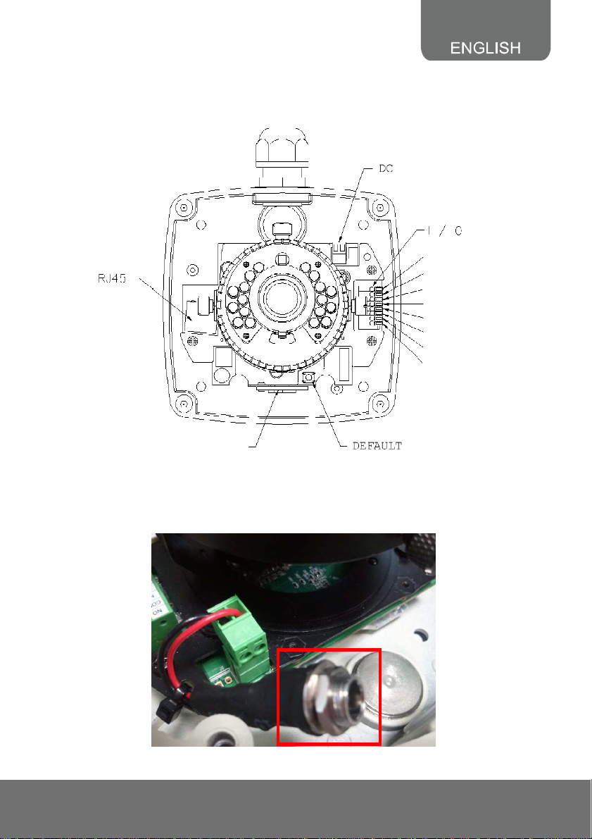
2. Connect power adaptor, then connect the IP camera to PC or network. Set up the network
configurations according to the network environment. The following picture shows a DC 12V
connector for adapter jack plug.
11
Page 16
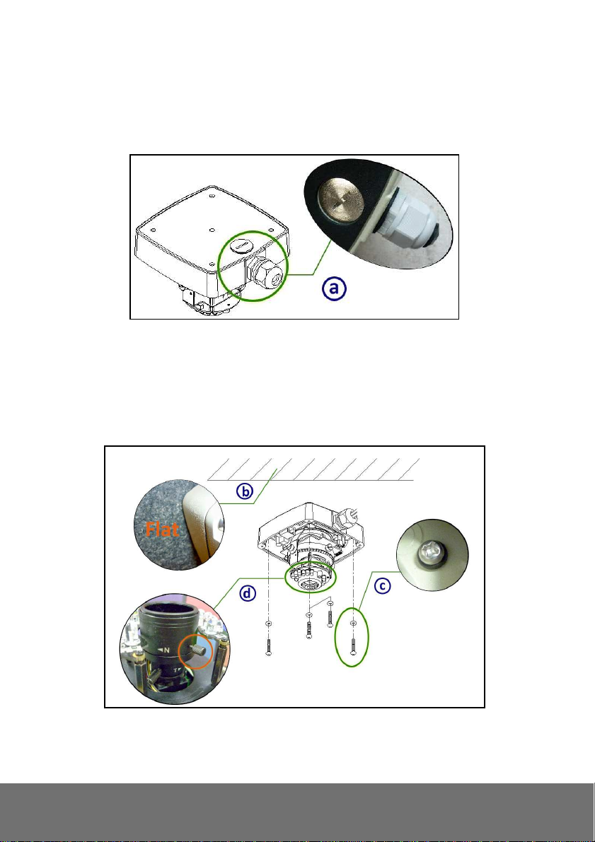
3. Installation Tips
In order to ensure IP66 waterproof level, please install the vandal dome according to the
instruction.
a. The Unused cable outlet hole must be closed, and the waterproof connector on the used hole
must be locked closely
b. We recommend the bottom of housing be set on the smooth flat and closely seal with the
surface.
c. When you mount the camera housing on the ceiling or wall, please use the screws with the
black rubber o-rings. Without the o-ring, the water may seep into the machine.
d. Turn and loose the control stick, shift right and left to adjust the vari-focal lens until the image
becomes clear, then turn and tighten the stick to fix it.
12
Page 17
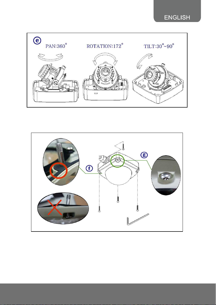
e. Use the 3-Axis bracket to adjust the camera to appropriate angle.
f. f. Before you close the dome cover, make sure that the black rubber band sticks to the inside
of the cover completely. Crook or uneven rubber band may cause the waterproof defective.
g. Lock tightly the screws on the dome cover to ensure there's no gap between the lid and base.
13
Page 18
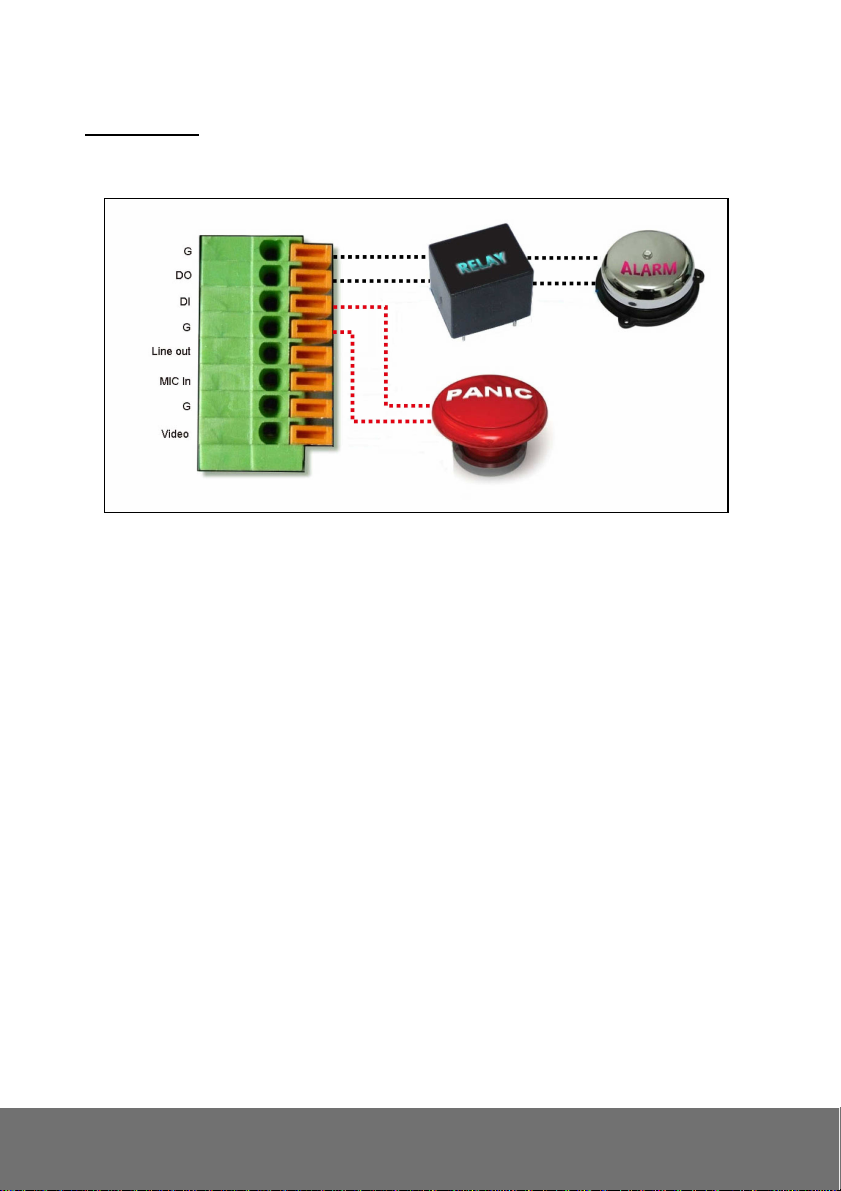
4. I/O Interface
I/O Connection
a. Please connect the GND & DO pin to the external relay (buzzer) device.
b. Please connect the GND & DI pin to the external trigger device
c. I/O PIN definition
GND (Ground): Initial state is LOW
DO (Digital Output): DC 5V
DI (Digital Input): Max. 50mA, DC 5V
14
Page 19

3.3 Factory Default
3.3.1 SF2111H-DR
1. To recover the default IP address and password, please follow the following steps.
2. Remove power, and press and hold the button. Please refer to the picture below.
Reset button
3. Power on the camera. Don’t release the button during the system booting.
4. It will take around 30 seconds to boot the camera.
5. Release the button when camera finishes proceed.
6. Re-login the camera using the default IP (http://192.168.1.200) or DHCP, and user name (admin),
password (admin).
15
Page 20

3.3.2 SF2111H-DVR
1. To recover the default IP address and password, please follow the following steps.
2. Remove power and Ethernet cable, press and hold the button for 10 sec. Please refer to the
picture below.
3. Connect power and Ethernet cable to the camera again. Power on the camera. Don’t release the
button during the system booting.
4. It will take around 30 seconds to boot the camera.
5. Release the button when camera finishes proceed.
6. Re-login the camera using the default IP (http://192.168.1.200) or DHCP, and user name (admin),
password (admin).
16
Page 21

4. SD card Compatibility List
SF2111H series is compliant with microSD/SDHC card and to ensure recording quality, and please use
memory cards over 2G and Class 4 above (Max. 32G)
microSD/SDHC card SD/SDHC
Transcend SDHC class4 16GB Transcend SDHC Class 4 16GB
Transcend SD class4 16GB Transcend SD Class 4 16GB
Transcend SDHC class4 32GB Transcend SDHC Class 4 32GB
Transcend SD class4 32GB Transcend SD Class 4 32GB
Transcend SD class6 4GB Transcend SD Class 6 4GB
Transcend SDHC class6 4GB Transcend SDHC Class 6 4GB
Transcend SD class6 8GB Transcend SD Class 6 8GB
Transcend SDHC class6 8GB Transcend SDHC Class 6 8GB
Transcend SD class6 16GB Transcend SD Class 6 16GB
Transcend SDHC class6 16GB Transcend SDHC Class 6 16GB
Transcend SDHC class10 4GB Transcend SDHC Class10 4GB
Transcend SDHC class10 8GB Transcend SDHC Class10 8GB
Transcend SDHC class10 16GB Transcend SDHC Class10 16GB
SanDisk SDHC class4 4GB SanDisk SDHC Class 4 4GB
SanDisk SDHC class4 8GB SanDisk SDHC Class 4 8GB
SanDisk SDHC class4 16GB SanDisk SDHC Class 4 16GB
SanDisk SDHC class4 32GB SanDisk SDHC Class 4 32GB
SF2111H-R/SF2111H-DR: SDHC/SD card
SF2111H-BR/SF2111H-DVR: microSDHC/SD card
17
Page 22

II. Monitor Setting
1. Right-click on the desktop. Select “ Properties”
2. Change “Color quality” to “Highest (32-bit)”.
18
Page 23

III. IP Assignment
There are two ways to find IP Camera:
− Finding IP Camera by using “NXU Lite recording software”
− Finding IP Camera by using “IP installer”
Finding IP Camera by using “NXU Lite recording software”
1. The NXU Lite software is in the attached software CD. Before launching it, please install the
software first. During the installing process, users will be required to input a User name and
Password for login NXU Lite system. Users can define the User name and Password as wishes.
Please refer to NXU Lite user manual for detailed installation instruction.
2. To run the application, double-click on your PC desktop or click Start > Programs > DVR >
NXU Lite. For security purpose, some of the features would require you to enter User name and
Password before it can be accessed. When the Authorization dialog box appears, key in your User
ID and Password. (If this is the first time, enter the one you have registered when installing the
software.
19
Click it to call out virtual
keyboard.
Page 24

3. Click “Setup” button.
4. Click “Add IPCam” button.
5. Select “IP Camera” item.
20
Page 25

6. Key in IP Camera’s ID and Password (default is admin/admin) and click “Auto Search” to find
camera.
7. In Search Result window, click it the IP camera model that user has purchased (Please ignore
ONVIF connection item); the camera is in red text that is configurable. User can double-click on
the camera is in red text and configure the IP camera’s setting; even the IP camera is not in the
same IP segment. Press “OK” to back to previous screen and press”Connect” to start live view.
Double-click the IP camera model
that user has purchased (ex:
SF2111H-BR, SF2111H-DVR).
Please ignore ONVIF
protocol selection; NXU Lite
doesn’t support ONVIF
connection.
21
Page 26
Finding IP Camera by using “IP installer”
1. Use the software, “IP Installer” to assign the IP address of the IP camera. The software is in the
attached software CD.
2. IP installer supports two languages
IPInstallerCht.exe: Traditional Chinese version
IPInstallerEng.exe: English version
3. There are 3 kinds of IP configuration.
Fixed IP (Public IP or Virtual IP)
DHCP (Dynamic IP)
DHCP server/router network automatically assigns IP addresses to devices. You can use the
IP Installer software in the CD to search for the IP camera(s) in the network.
Dial-up (PPPoE)
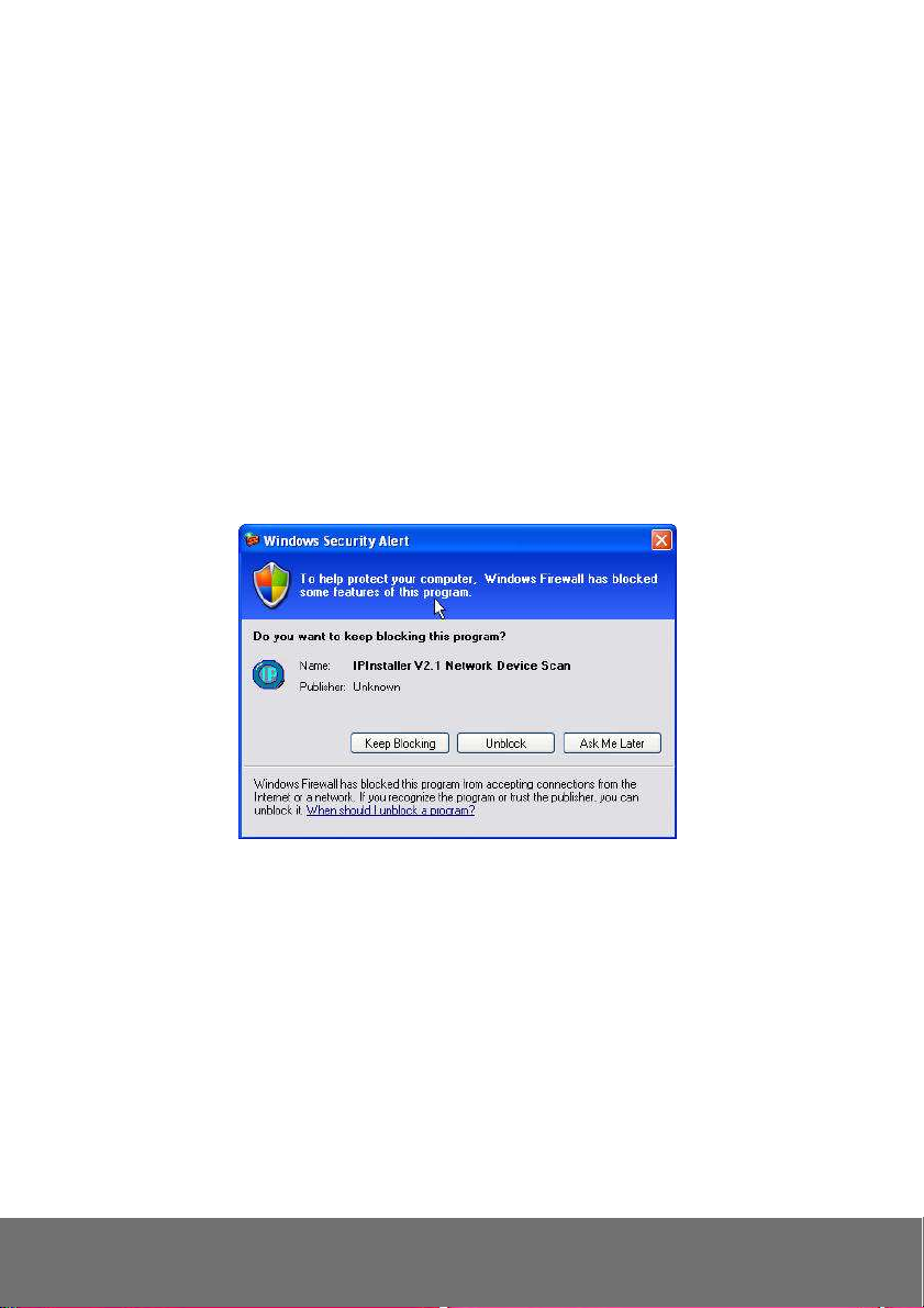
4. Execute IP Installer
5. For Windows® XP (SP2) users, the following message box may appear. Please click “Unblock”.
22
Page 27
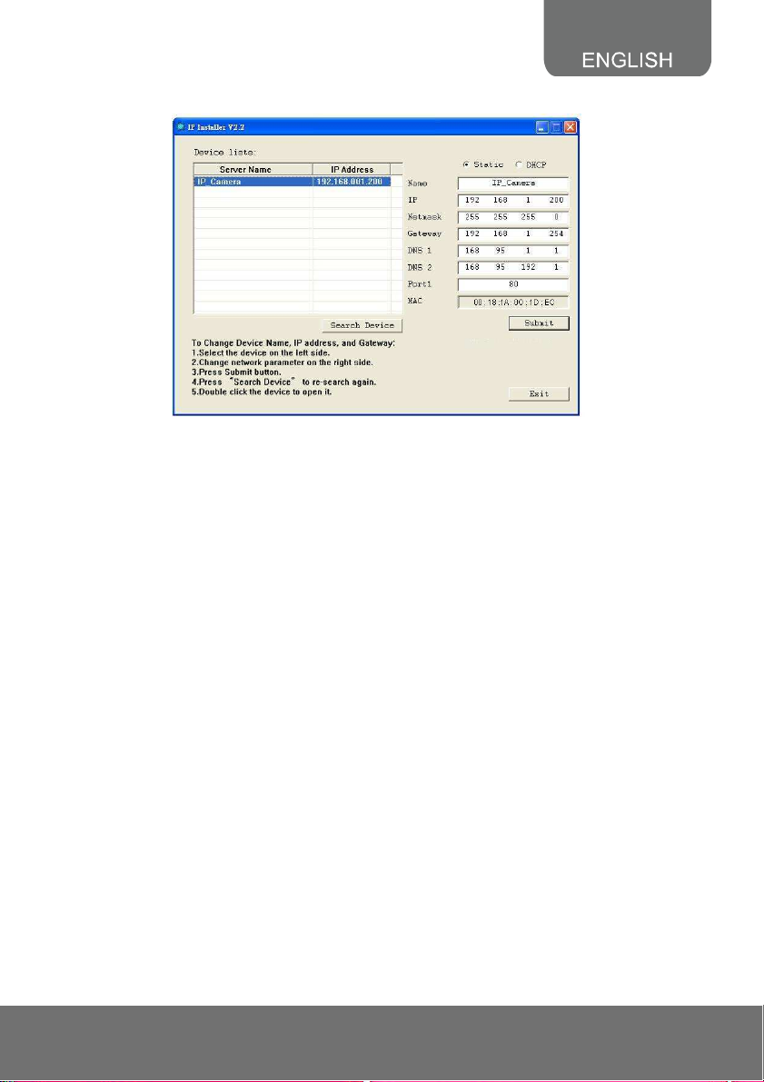
IP Installer configuration:
6. IP Installer will search all IP cameras connected on the LAN. The user can click “Search Device”
to search again.
7. Click one of the IP cameras listed on the left side. The network configuration for this IP camera will
show on the right side. You may change the name of the IP camera to your preference (eg: Office,
warehouse) in “Name” on the right side.
[Note] The server name length has to be less than 15 digits.
23
Page 28

Using DHCP Server/Router Network
To use DHCP, please check DHCP and click “Submit” then click “OK”. It will apply the change and
reboot the Device.
Please left-click the mouse twice on a selected IP camera in “Device lists” in IP Installer. Upon doing so,
the Internet Explorer browser should open.
24
Page 29
Using NON-DHCP Server/Router Network
In Non-DHCP server/router network, the static IP address must be assigned to the device each time
when adding another IP camera to the network; the default IP address of the current one must be
changed to avoid conflict.
Please make sure the Subnet of the PC’s IP address and the IP camera’s IP address are the same.
[Example]
The same Subnet:
IP camera IP address: 192.168.1.200
PC IP address: 192.168.1.100
Different Subnets:
IP camera IP address: 192.168.2.200
PC IP address: 192.168.1.100
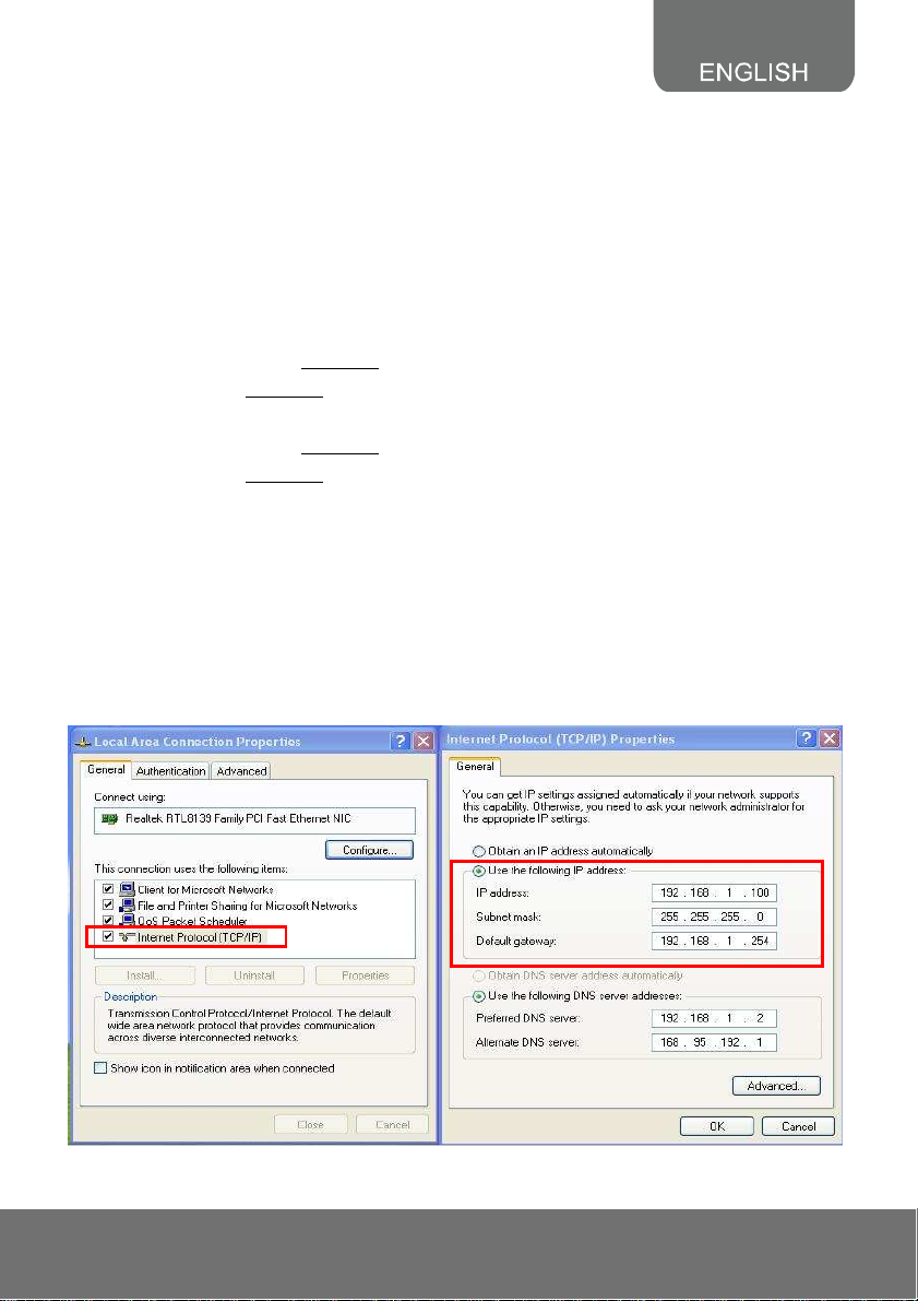
To Change PC IP Address:
Control PanelNetwork ConnectionsLocal Area Connection PropertiesInternet Protocol
(TCP/IP) Properties
Please make sure your IP camera and PC have the same Subnet. If not, please change IP
camera subnet or PC IP subnet accordingly.
PC’s IP address:
25
Page 30
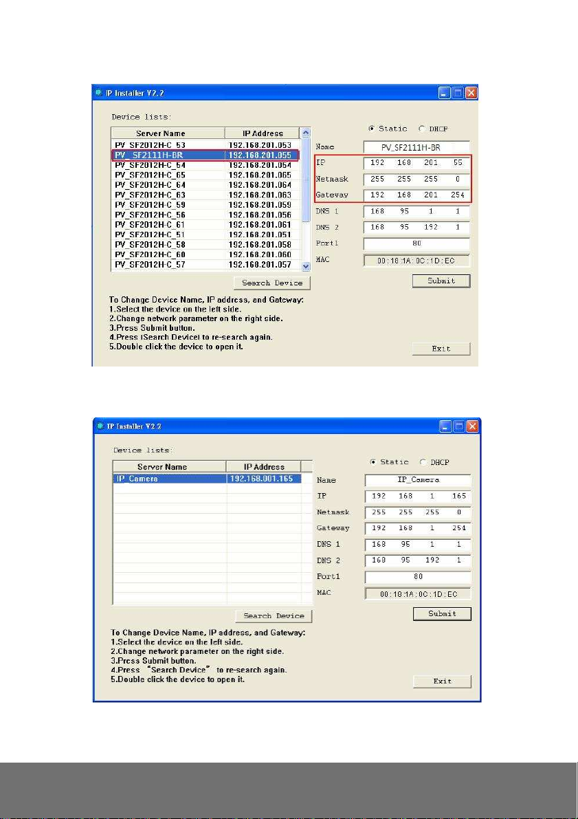
IP camera IP addresses:
8. A quick way to access remote monitoring is to left-click the mouse twice on a selected IP camera in
“Device lists” in IP Installer. Upon doing so, the Internet Explorer browser should open.
26
Page 31
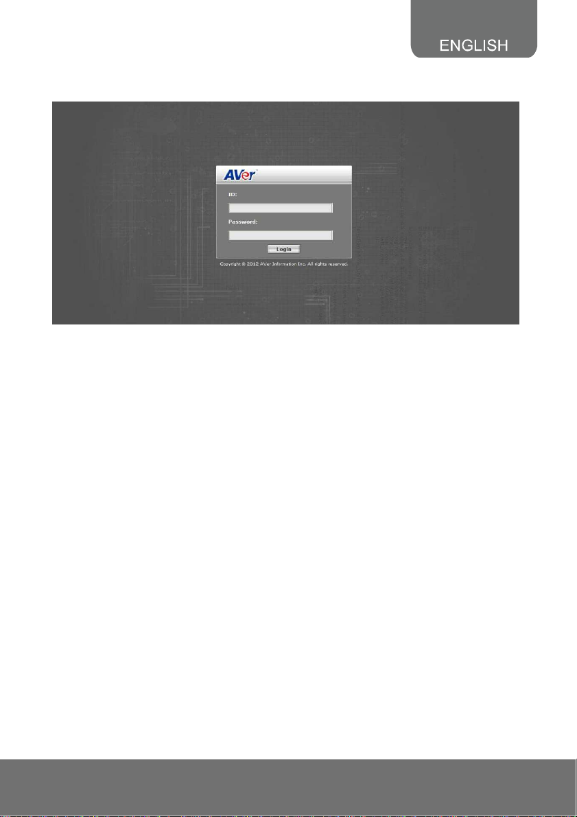
9. Then, please key in the default “User name” and “Password”, both of which are “admin”.
27
Page 32
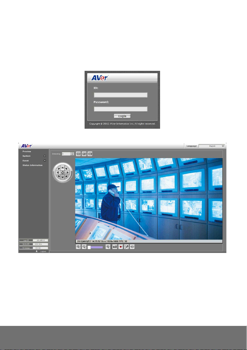
IV. Connecting the IP Camera
Launch the Internet Explorer browser, type the IP address of the IP camera in the address field. It will
show the following dialogue box. Key-in the”ID” and “Password”. The default”ID” and “Password” are
both “admin”.
Once connected to the IP camera, the following program interface will appear.
28
Page 33

COPYRIGHT
© 2012 AVer Information Inc. All rights reserved.
All rights of this object belong to AVer Information Inc. Reproduced or transmitted in any form, or
by any means without the prior written permission of AVer Information Inc. is prohibited. AVer
Information Inc. reserves the rights to modify its products, including their specifications and any
other information stated herein without notice. The official printout of any information shall prevail
should there be any discrepancy between the information contained herein and the information
contained in that printout. “AVer” is a trademark owned by AVer Information Inc. Other
trademarks used herein for description purpose only belong to each of their companies.
NOTICE
SPECIFICATIONS ARE SUBJECT TO CHANGE WITHOUT PRIOR NOTICE. THE
INFORMATION CONTAINED HEREIN IS TO BE CONSIDERED FOR REFERENCE ONLY.
WARNING
TO REDUCE RISK OF FIRE OR ELECTRIC SHOCK, DO NOT EXPOSE THIS APPLIANCE TO
RAIN OR MOISTURE. WARRANTY VOID FOR ANY UNAUTHORIZED PRODUCT
MODIFICATION.
THE MARK OF CROSSED-OUT WHEELED BIN INDICATES THAT THIS
PRODUCT MUST NOT BE DISPOSED OF WITH YOUR OTHER HOUSEHOLD
WASTE. INSTEAD, YOU NEED TO DISPOSE OF THE WASTE EQUIPMENT BY
HANDING IT OVER TO A DESIGNATED COLLECTION POINT FOR THE
RECYCLING OF WASTE ELECTRICAL AND ELECTRONIC EQUIPMENT. FOR
MORE INFORMATION ABOUT WHERE TO DROP OFF YOUR WASTE
EQUIPMENT FOR RECYCLING, PLEASE CONTACT YOUR HOUSEHOLD
WASTE DISPOSAL SERVICE OR THE SHOP WHERE YOU PURCHASED THE
PRODUCT.
29
Page 34

Limited Warranty
AVer Information, Inc. (“AVer”) warrants that the applicable product (“Product”) substantially conforms
to AVer’s documentation for the product and that its manufacture and components are free of defects
in material and workmanship under normal use. “You” as used in this agreement means you
individually or the business entity on whose behalf you use or install the product, as applicable. This
limited warranty extends only to You as the original purchaser. Except for the foregoing, the Product is
provided “AS IS.” In no event does AVer warrant that You will be able to operate the Product without
problems or interruptions, or that the Product is suitable for your purposes. Your exclusive remedy
and the entire liability of AVer under this paragraph shall be, at AVer’s option, the repair or replacement
of the Product with the same or a comparable product. This warranty does not apply to (a) any Product
on which the serial number has been defaced, modified, or removed, or (b) cartons, cases, batteries,
cabinets, tapes, or accessories used with this product. This warranty does not apply to any Product
that has suffered damage, deterioration or malfunction due to (a) accident, abuse, misuse, neglect, fire,
water, lightning, or other acts of nature, commercial or industrial use, unauthorized product
modification or failure to follow instructions included with the Product, (b) misapplication of service by
someone other than the manufacturer’s representative, (c) any shipment damages (such claims must
be made with the carrier), or (d) any other causes that do not relate to a Product defect. The Warranty
Period of any repaired or replaced Product shall be the longer of (a) the original Warranty Period or (b)
thirty (30) days from the date of delivery of the repaired or replaced product.
Limitations of Warranty
AVer makes no warranties to any third party. You are responsible for all claims, damages, settlements,
expenses, and attorneys’ fees with respect to claims made against You as a result of Your use or
misuse of the Product. This warranty applies only if the Product is installed, operated, maintained, and
used in accordance with AVer specifications. Specifically, the warranties do not extend to any failure
caused by (i) accident, unusual physical, electrical, or electromagnetic stress, neglect or misuse, (ii)
fluctuations in electrical power beyond AVer specifications, (iii) use of the Product with any accessories
or options not furnished by AVer or its authorized agents, or (iv) installation, alteration, or repair of the
Product by anyone other than AVer or its authorized agents.
Disclaimer of Warranty
EXCEPT AS EXPRESSLY PROVIDED OTHERWISE HEREIN AND TO THE MAXIMUM EXTENT
PERMITTED BY APPLICABLE LAW, AVER DISCLAIMS ALL OTHER WARRANTIES WITH
RESPECT TO THE PRODUCT, WHETHER EXPRESS, IMPLIED, STATUTORY OR OTHERWISE,
INCLUDING WITHOUT LIMITATION, SATISFACTORY QUALITY, COURSE OF DEALING, TRADE
USAGE OR PRACTICE OR THE IMPLIED WARRANTIES OF MERCHANTABILITY, FITNESS FOR A
PARTICULAR PURPOSE OR NONINFRINGEMENT OF THIRD PARTY RIGHTS.
Limitation of Liability
IN NO EVENT SHALL AVER BE LIABLE FOR INDIRECT, INCIDENTAL, SPECIAL, EXEMPLARY,
PUNITIVE, OR CONSEQUENTIAL DAMAGES OF ANY NATURE INCLUDING, BUT NOT LIMITED
TO, LOSS OF PROFITS, DATA, REVENUE, PRODUCTION, OR USE, BUSINESS INTERRUPTION,
OR PROCUREMENT OF SUBSTITUTE GOODS OR SERVICES ARISING OUT OF OR IN
CONNECTION WITH THIS LIMITED WARRANTY, OR THE USE OR PERFORMANCE OF ANY
PRODUCT, WHETHER BASED ON CONTRACT OR TORT, INCLUDING NEGLIGENCE, OR ANY
OTHER LEGAL THEORY, EVEN IF AVER HAS ADVISED OF THE POSSIBILITY OF SUCH
DAMAGES. AVER’S TOTAL, AGGREGATE LIABILITY FOR DAMAGES OF ANY NATURE,
REGARDLESS OF FORM OF ACTION, SHALL IN NO EVENT EXCEED THE AMOUNT PAID BY
YOU TO AVER FOR THE SPECIFIC PRODUCT UPON WHICH LIABILITY IS BASED.
30
Page 35

Governing Law and Your Rights
This warranty gives you specific legal rights; You may also have other rights granted under state law.
These rights vary from state to state.
31
 Loading...