

Installation Instruction
Mooney M20
Series
www.aveoengineering.com

Mooney M20 series Installation Instruction s
AVE-MOD-012-INS
Issue 02
__________________________________________________________________________________
Aveo Engineering Group, s.r.o.
Drasov 202, 261 01 Drasov
Czech Republic
Issue of form 01
Page 2 of 21
Table of Contents
PART 0
MANUAL ADMINISTRATION 3
0.1 DOCUMENT APPROVAL 3
0.2 AMENDMENT RECORD PROCEDURE 4
0.3 AFFECTED PAGES PROCEDURE 4
PART 1 INSTALLATION INSTRUCTION 5
1.1 GENERAL 5
1.2 CONTINUED AIRWORTHINESS 5
1.3 DESCRIPTION 6
1.3.1 Wingtip lights 6
1.3.2 Aft position light 7
1.3.3 Anti-collision lights 7
1.3.4 Taxi- and landing lights 7
1.4 WINGTIP MODIFICATION 8
1.4.1 Option A - Replacement of Light Unit 8
1.4.2 Option B - Wingtip Replacement 11
1.5 REAR POSITION LIGHT INSTALLATION 13
1.6 ANTI-COLLLISION LIGHTS INSTALLATION 15
1.7 TAXI AND LANDING LIGHTS INSTALLATION 16
1.7.1 Wing inst allation 16
1.7.2 Cowling installation 19
PART 2 COMPLIANCE DEMONSTRATION 21
Mooney M20 series Installation Instruction s
AVE-MOD-012-INS
Issue 02
__________________________________________________________________________________
Aveo Engineering Group, s.r.o.
Drasov 202, 261 01 Drasov
Czech Republic
Issue of form 01
Page 3 of 21
Part 0 Manual Administration
0.1 Document approval
This document has been established in accordance with an alternative procedure to
DOA approved under EASA AP429.
This ins t allatio n Instruction is applicable for the Mooney models M20J, M20K, M20L
and M20S.
Compiled by: 19. – Dec. - 2018
Petr Jaroš
Engineer, Aveo Engineering Group, s.r.o.
Approved by: 19. – Dec. - 2018
Georg Hartl
Head of DO, Aveo Engineering Group, s.r.o.
Mooney M20 series Installation Instruction s
AVE-MOD-012-INS
Issue 02
__________________________________________________________________________________
Aveo Engineering Group, s.r.o.
Drasov 202, 261 01 Drasov
Czech Republic
Issue of form 01
Page 4 of 21
0.2 Amendment Record procedure
The master copy of this document shall be kept electronically as a read only
document under the control of Aveo Engineering Group, s.r.o. as Master Copy.
ALL amendments to this manual will initiate a raise of Issue
ALL raises of issue will be given a sequential Alphabetic Issue Ident sequentially
from 01 to 99 in Table 01 - Issue No: Column– Initial Issue of Document will be
“01”
ALL Issues of this document will be approved by Head of DO
0.3 Affected Pages Procedur e
ALL pages affected by ANY raise of issue of this document will be listed in Table 01 Affected Pages Column.
The reason(s) for ALL ra ise of issu e and desc ripti on of change du e to raise of issue will be
provided for ALL raises of issu e in Table 01 - Details Column.
Changes from the previous issue are highlighted by YELLOW HIGHLIGHTING over new
content. AND YELLOW HIGHLIGHTING AND CROSSING OUT of deleted content.
Example (CROSSING OUT)
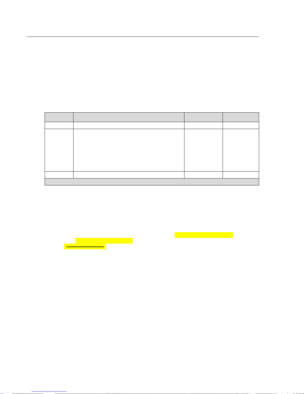
Issue
No.
Details Date
Affected
Pages
01 Initial Issue 28.Aug.2018 ALL
02
Remove models M20M, M20R, M20TN , M20U,
M20V(not marked)
Correct references to installation manuals and
AMM SUP
Add remark
Add standard for wire
Correct instruction for tip installation, add EN 2267
reference, remove preheating (not marked)
Add balancing of rudder
19.Dec.2018
3
5
10
12
14
Table 01: Document Amendment Record Table

Mooney M20 series Installation Instruction s
AVE-MOD-012-INS
Issue 02
__________________________________________________________________________________
Aveo Engineering Group, s.r.o.
Drasov 202, 261 01 Drasov
Czech Republic
Issue of form 01
Page 5 of 21
Part 1 Installation Instruction
1.1 General
This ins t allatio n is to be performed in accordance to common practice as described in
FAR AC 43.13-2B Chapter 4 and in FAR AC 43.13 1B Chapter 11 Section 15 (Bonding)
as published by FAA.
The installer is responsible to follow the installation instructions in the latest revision
of:
• FAR AC 43.13-2B Chapter 4
• FAR AC 43.13 1B Chapter 11 Section 15
• AVE-WPS-64G-IM
• AVE-PSPSYW-IM
• AVE-RBXP-001-IM
• AVE-CCPS-IM
• AVE-H30-002-IM
• AVE-SDD45-IM
All drawings applicable for this change are listed in the Drawing List:
• AVE-MOD-012-DL, issue 01
The following appliances carry an ETSO authorization:
• AVE-WPSR-64G & AVE-WPSG-64G – ETSOA 210.10053936
• AVE-RBXPR-001 – ETSOA 210.10055069
The change is to be performed using the document AVE-MOD-012-MCS in the latest
issue.
The aircraft modified according to this instruction may not be released back to service
without the EASA design approval certificate being provided.
1.2 Continued Airworthiness
The aircraft manuals remain fully valid. The inspection intervals and the procedures of
the aircraft override the general statements in the component manuals as listed under
§1.1.
For inspection of the new lights themsel ves follow the procedure of the AMM
supplement AVE-MOD-012-SUP-AMM.
Mooney M20 series Installation Instruction s
AVE-MOD-012-INS
Issue 02
__________________________________________________________________________________
Aveo Engineering Group, s.r.o.
Drasov 202, 261 01 Drasov
Czech Republic
Issue of form 01
Page 6 of 21
1.3 Description
This modification is the replacement or new installation of the composite wingtip
segment and of position, anti-collision, taxi- and landing lights by LED type lights.
1.3.1 Wingtip lights
This modification allows on aircraft which already have a composite wingtip to replace
either the complete wingtip or only the light unit inside or outside the original
composite wingtip. The Mooney also exists in versions without a composite wingtip at
all. For those aircraft the light unit can be replaced. Aircraft which originally have no
composite wingtip cannot be equipped with the Aveo wingtip.
Aveo designed a new wingtip with integrated position lights type I and II including the
strobe function.
Alternatively the originally wingtip lights on aircraft with or without wingtip can be
replaced by the Aveo Ultra Galactica embedded without installation or replacement of
the conformal wingtip. The Ultra Galactica e mbedded also fulfills the requirement for
position lights type I and II plus the strobe function.
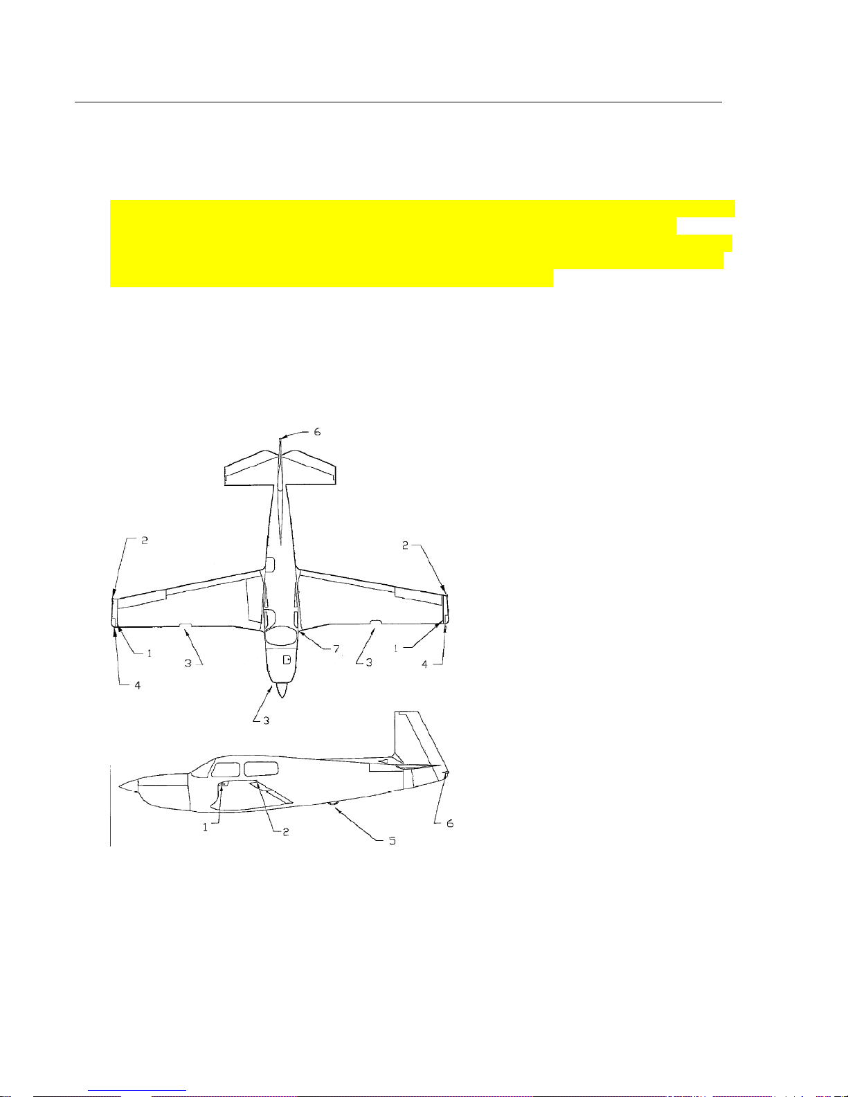
1. Light assembly navigation &
strobe
2. Wingtip
3. Landing / Taxi light installation
LH, RH and cowling
4. Recognition light installation
5. Beacon installation
6. Strobe assembly tail
7. Ice retrofit
Synchronization:
The strobe lights may be synchronized but the frequency of the strobes is so low that
synchronization of the lights is not required.
For the synchronization function the blue wires of each light to be synchronized have
to be connected. If for this function additional wires are to be installed then these
must be installed along the wire bundle in which the lights power wires run. If the
function is not used the blue wire at each light is to be capped and stowed.

Mooney M20 series Installation Instruction s
AVE-MOD-012-INS
Issue 02
__________________________________________________________________________________
Aveo Engineering Group, s.r.o.
Drasov 202, 261 01 Drasov
Czech Republic
Issue of form 01
Page 7 of 21
1.3.2 Aft position light
The aft position light can be replaced by Aveo PosiStrobe CP. The light is a direct
replacement. For synchronization applies description under section 1.3.1.
1.3.3 Anti-collision lights
The originally installed anticollision light can be replaced by Aveo RedBaron XP red
including the adapter.
1.3.4 Taxi- and landing lights
The M20 can be equipped with a taxi light (wide angle lens) and a landing light
(narrow angle). This modification allows replacing all insta lled taxi and landing lights
with the same configuration as installed before the modification. A configuration
change is not allowed.

Mooney M20 series Installation Instruction s
AVE-MOD-012-INS
Issue 02
__________________________________________________________________________________
Aveo Engineering Group, s.r.o.
Drasov 202, 261 01 Drasov
Czech Republic
Issue of form 01
Page 8 of 21
1.4 Wingtip Modification
1.4.1 Option A - Replacement of Light Unit

Mooney M20 series Installation Instruction s
AVE-MOD-012-INS
Issue 02
__________________________________________________________________________________
Aveo Engineering Group, s.r.o.
Drasov 202, 261 01 Drasov
Czech Republic
Issue of form 01
Page 9 of 21
25 21
24
22 (3x)
23
24
25
26
27

Mooney M20 series Installation Instruction s
AVE-MOD-012-INS
Issue 02
__________________________________________________________________________________
Aveo Engineering Group, s.r.o.
Drasov 202, 261 01 Drasov
Czech Republic
Issue of form 01
Page 10 of 21
Figure
and
Index
Number
Part Number Description
Parts
Avail.
QTY.
Per
assy.
21
22
23
24
25
26
27
AVS-P000100175-A60
AVS-SCC0510LHS-C0A
AVS-P001290550-A1A
AVE-WPSR-64G
AVE-WPSG-64G
AVS-SCM05045LHS-D0A
01-0430011-00
01-0410823
Ultra Galactica Adapter
Screw#6-32 x3/8" LPSHS
Gasket
Ultra Galactica Embedded Red
Ultra Galactica Embedded Green
Mounting Screw M5 x 45
Connector Kit – Male
Connector Kit - Female
2
6
2
1
1
2
2
2
1
2
3
4
5
6
7
8
9
10
11
12
13
18
19
20
Original parts
Several
210384
Several
Several
Several
Several
Several
W1250PR
MS24693-S28
Several
210409-003
Several
RH-50-7.5
Several
921001
Several
Wingtip assy LH (RH similar)
Lens, Wingtip
Light assy strobe (14 or 28V)
Screw Strobe light 14 V
Screw Strobe light 14 V or Strobe Nav.
Light 28 V
Retainer LH (RH similar)
Bracket, Mounting LH (RH similar)
Light assy Nav. 14V
Screw Nav light assembly
Screw, washer, nut
Retainer
Recognition light
Resistor
Power Supply
Plate, Cover RH/LH
Wire loom power supply to wingtip
REF
REF
REF
AR
AR
REF
REF
REF
4
2
2
2
2
2
2
2
NOTES
1. Remove both position and the strobe lights (items 3 to 5 and 8 to 10) in
accordance to the aircraft maintenance manual.
2. Disconnect the wire bundle from the position and the strobe light
3. Inspect the installation area for corrosion and correct according to AMM if
required
4. Install item 21 to 25 as described. Holes on bracket items 6 and 7 are to be
drilled on installation and anchor nuts installed as required. Items 6 to 7 may be
trimmed as necessary. After trimming remove sharp edges and apply primer.
5. Remove the strobe power supply (item 18) and wire loom (item 20).
6. Add connector (item 26) to the wires of the light (it em 24) and connector (item
27) to the aircraft wiring. Extend the wiring if necessary in accordance to
common practice FAR AC 43.13-2B Chapter.
7. In case synchronization is to be connected and no wire available then add a wire
with minimum gage 22 (standard EN 2267 or equivalent) to connect both wi ngtip
and the aft position light (all blue wires). The synchronization wires are not to be
connected to 28 V or GND.
8. Re-install cover (item 19)
Remark: item 21 may be installed with the two forward screws only in cases where
the aft screw cannot be placed (e.g. existing cut out)

Mooney M20 series Installation Instruction s
AVE-MOD-012-INS
Issue 02
__________________________________________________________________________________
Aveo Engineering Group, s.r.o.
Drasov 202, 261 01 Drasov
Czech Republic
Issue of form 01
Page 11 of 21
1.4.2 Option B - Wingtip Replacement
1, 2 9 10
19
17
16
17
16
15
14
13
12
5
3
4 6 7 7 8
8

Mooney M20 series Installation Instruction s
AVE-MOD-012-INS
Issue 02
__________________________________________________________________________________
Aveo Engineering Group, s.r.o.
Drasov 202, 261 01 Drasov
Czech Republic
Issue of form 01
Page 12 of 21
Figure
and
Index
Number
Part Number Description
Parts
Avail.
QTY.
Per
assy.
1
2
3
4
5
6
7
8
9
10
AVS-C230105898-A40
AVS-C230105897-A40
AVS-C130106889-A00
AVS-C130106888-A00
AVE-CCPSG-R01
AVE-CCPSR-R01
AVS-C210105961-A40
AVS-C210105960-A40
AVS-SCM05030HAS-D0A
AVS-WNM0432EFN-D0A
AVS-SCM05008HAS-D0A
AVS-WAM0432DFS-D0A
01-0430011-00
01-0410823
Wingtip Fiberglass subassembly right
Wingtip Fiberglass subassembly left
Wingtip Carbon subassembly right
Wingtip Carbon subassembly left
Raised Conforma – Green
Raised Conforma – Red
Light Holder w. nuts R
Light Holder w. nuts L
Screw
Washer
Screw
Washer
Connector Kit – Male
Connector Kit - Female
1
1
1
1
1
1
1
1
4
4
6
6
2
2
12
13
14
15
16
17
18
19
20
Original parts
Several
Several
MS24694-4
Several
220000
210047
Several
921001
Several
Glare fence RH (LH similar)
Lens, Wingtip RH (LH similar)
Screw
Original wingt ip composite assy RH (LH
similar)
Skin Wing
Rib Assy
Power Supply
Plate, Cover RH/LH
Wire loom power supply to wingtip
REF
REF
REF
1 (1)
REF
REF
REF
2
2
2
NOTES
1. Remove both position and the strobe lights (items 3 to 5 and 8 to 10) in
accordance to the aircraft maintenance manual.
2. Disconnect the wire bundle from the position and the strobe light
3. Inspect the installation area for corrosion and correct according to AMM if
required
4. Install item 1 to 8 as described and in accordance with Aircraft Service Manual
for replacing wingtip (57-20-02). For installation of carbon wingtips (item 2) the
rivets have to be installed wet (PRC).
5. Remove the strobe power supply (item 18) and wire loom (item 20).
6. Add connector (item 9) to the wires of the light (item 3) and connector (item 10)
to the aircraft wiring. Extend the wiring if necessary in accordance to common
practice FAR AC 43.13-2B Chapter.
7. In case synchronization is to be connected and no wire available then add a wire
with minimum gage 22 (standard EN 2267 or equivalent) to connect both wingtip
and the aft position light (all blue wires). The synchronization wires are not to be
connected to 28 V or GND.
8. Re-install cover (item 19)

Mooney M20 series Installation Instruction s
AVE-MOD-012-INS
Issue 02
__________________________________________________________________________________
Aveo Engineering Group, s.r.o.
Drasov 202, 261 01 Drasov
Czech Republic
Issue of form 01
Page 13 of 21
1.5 Rear Position Light Installation
A
A
A
Original Installation:
New Installation:
2
1
3

Mooney M20 series Installation Instruction s
AVE-MOD-012-INS
Issue 02
__________________________________________________________________________________
Aveo Engineering Group, s.r.o.
Drasov 202, 261 01 Drasov
Czech Republic
Issue of form 01
Page 14 of 21
Figure
and
Index
Number
Part Number Description
Parts
Avail.
QTY.
Per
assy.
1
2
3
-------
24
25
26
27
28
29
30
31
32
33
34
35
AVE-PSPSYW-T01
MS-16995-19
AVS-P000105638-A10
---------------------------Original parts
Several
470004-003
470004-005
A6-120
Several
Several
Several
Several
Several
Several
Several
1-480305
470011-001
PosiStrobe Titania
Screw #6-32 Thread, 5/8“ SHCS
Gasket
------------------------------------------------
Ring
Plate
Rivet Nut
Nav light / Strobe light assy
Screw 6-32
Retainer
Lens
Gasket
Bulb
Base assembly
Connector
Shield
------
1
2
1
-----
1
1
2
1
2
1
1
1
1
1
1
1
NOTES
1. Remove position light in accordance to the aircraft maintenance manual.
2. Disconnect the wire bundle from the position light
3. Inspect the installation area for corrosion and correct according to AMM if
required
4. Splice the new light’s wires into the existing connector according to the
referenced installation manuals and the common practice FAR AC 43.13-2B
Chapter 4
5. In case strobe light and synchronization wire are to be added then run two wires
with minimum wire gage 22 parallel to the position light wire bundle. The wires
are to be connected to the corresponding wires of the wing tip lights. The strobe
light might also be operated together with the position light due to low power
consumption or bot h fun c t ions may not be used (just not con n ected).
6. Install items 1, 2, 3 as described.
7. After installation of the light balance the ruder according to AMM chapter 27-93-
01

Mooney M20 series Installation Instruction s
AVE-MOD-012-INS
Issue 02
__________________________________________________________________________________
Aveo Engineering Group, s.r.o.
Drasov 202, 261 01 Drasov
Czech Republic
Issue of form 01
Page 15 of 21
1.6 Anti-colllision Lights Installation
Figure
and
Index
Number
Part Number Description
Parts
Avail.
QTY.
Per
assy.
1
2
3
4
AVS-P000102111-A3A
AVE-RBXPR-001
AN526-632R6
AVS- P000600093-A60
BOTTOM ANTI-COLLISION LIGHT
INSTALLATION
Hex Socket Metric Screw Assy
RedBaron XP Galactica
Original Fasteners
RedBaron XP Light Replacement Adapter 2
1
1
5
1
NOTES
1. Remove lower flashing or rotating beacon in accordance to the aircraft
maintenance manual.
2. Disconnect the wire bundle from the flashing beacon
3. Inspect the installation area for corrosion and correct according to AMM if
required
4. Splice the new light’s wires into the existing connector according to the
referenced installation manuals and the common practice FAR AC 43.13-2B
Chapter 4
5. Install items 1 to 4 as described above.
A
View A
1 2 3
4

Mooney M20 series Installation Instruction s
AVE-MOD-012-INS
Issue 02
__________________________________________________________________________________
Aveo Engineering Group, s.r.o.
Drasov 202, 261 01 Drasov
Czech Republic
Issue of form 01
Page 16 of 21
1.7 Taxi and Landing Lights Installation
1.7.1 Wing installation

Mooney M20 series Installation Instruction s
AVE-MOD-012-INS
Issue 02
__________________________________________________________________________________
Aveo Engineering Group, s.r.o.
Drasov 202, 261 01 Drasov
Czech Republic
Issue of form 01
Page 17 of 21
20

Mooney M20 series Installation Instruction s
AVE-MOD-012-INS
Issue 02
__________________________________________________________________________________
Aveo Engineering Group, s.r.o.
Drasov 202, 261 01 Drasov
Czech Republic
Issue of form 01
Page 18 of 21
Figure
and
Index
Number
Part Number Description
Parts
Avail.
QTY.
Per
assy.
20
------1
2
3
4
5
6
7
8
9
10
11
12
13
14
15
AVE-H30TATSNL-T0A
---------------------------Original parts
Several
2102118-001
210204-501
210204-003
4596
MS35206-251
SMB003-0200-9
AN515-8R6
210216-502
210216-003
MS21080-08
210213-502
210418-501
210418-502
210418-003
Hercules Drop-in Landing
-----------------------------------------------Lens
Retainer RH (LH similar)
Plate assembly LH/RH
Retainer
Lamp, LH/RH (GE)
Screw
Mount (Lord) LH/RH
Screw
Bracket RH (LH similar)
Flange LH/RH
Nutplate
Doubler assy RH (LH similar)
Reflector installation taxi light RH
(LHsimilar)
Bracket, RH (LH similar)
Reflector RH/LH
------
2
----1
1
1
1
2
4
2
2
1
2
4
1
1
1
1
NOTES
1. Replace landing light bulb (item 5) in accordance to the aircraft maintenance
manual by new LED landing light (item 20). Regard polarity of the new light.

Mooney M20 series Installation Instruction s
AVE-MOD-012-INS
Issue 02
__________________________________________________________________________________
Aveo Engineering Group, s.r.o.
Drasov 202, 261 01 Drasov
Czech Republic
Issue of form 01
Page 19 of 21
1.7.2 Cowling installation
1

Mooney M20 series Installation Instruction s
AVE-MOD-012-INS
Issue 02
__________________________________________________________________________________
Aveo Engineering Group, s.r.o.
Drasov 202, 261 01 Drasov
Czech Republic
Issue of form 01
Page 20 of 21
Figure
and
Index
Number
Part Number Description
Parts
Avail.
QTY.
Per
assy.
1
------7
11
12
13
14
15
16
17
18
19
AVE-SDD45LW-T02
AVE-SDD45LW-T03
---------------------------Original parts
Several
650188-501
650230-501
GE 4522
GE 4553
650187-001
MS21045L08
AN960-B
LC-038D-3
AN526-832R6
MS210-78-08
650189-001
650190-001
MS24694-S5
A3135-017-3
MS21078-08
Samson Drop-In Landing 28V DC
Samson Drop-In Landing 14V DC
----------------------------------------------Cowling
Ring Assy
Ring Assy
Bulb, Landing Light (14 V)
Bulb Landing Light (28 V)
Retainer Landing Light
Nut
Washer
Spring
Screw
Nutplate
Lens Landing Light
Retainer
Screw
Washer
Nutplate
------
1
1
----REF
1
1
1
1
1
3
6
3
3
1
1
1
8
8
8
NOTES
1. Replace landing light bulb (item 13) in accordance to the aircraft maintenance
manual by new LED landing light (item 1). Assure that the replacement has
correct voltage. Regard polarity of the new light.

Mooney M20 series Installation Instruction s
AVE-MOD-012-INS
Issue 02
__________________________________________________________________________________
Aveo Engineering Group, s.r.o.
Drasov 202, 261 01 Drasov
Czech Republic
Issue of form 01
Page 21 of 21
Part 2 Compliance demonstration
This document is in relation to the certification program AVE-MOD-012-PFC.
The compliance is demonstrated for the following certification specification:
Requirements
MoC
Statement of Compliance
CS 23.2500
General requirements
on systems and
equipment function
MoC 0
CS 23.1301
(a) All navigation and anti-collision lights are ETSO
certified. All landing lights are qualified according to
RTCA DO160 as per AVE-H30-001-CCL.
(b) Not applicable as no changes are made which
would require a changed or a new label.
(c) All equipment is installed within their limits.
(d) It has been proven in other installation and by
the qualification data that all equipment is
functional for the intended purpose. Additionally the
proper function is determined in a functional check
as per MCS.
CS 23.1309
(a) All products have been tested to the appropriate
environmental standard. In addition to that
improves the new light installation the mean time
between failure by a factor of about 1000. All lights
are brighter at a lower power consumption and a
much lower temperature.
CS 23.2625
Instructions for
Continued
Airworthiness
MoC 0
CS 23.1529
The modification includes a supplement to Mooney
Aircraft Maintenance Manual (AMM) modified by
Aveo Modification “AVE MOD 012”.
 Loading...