

Page 1
© Aveo Engineering Group, s.r.o.
www.aveoengineering.com
Revision
Date
Change Description
Approval
Initial
01/Oct/2017
N/A
Installation Manual
Page 2
Installation Manual
Valid from: 01/Oct/2017
1. PRODUCT INFO
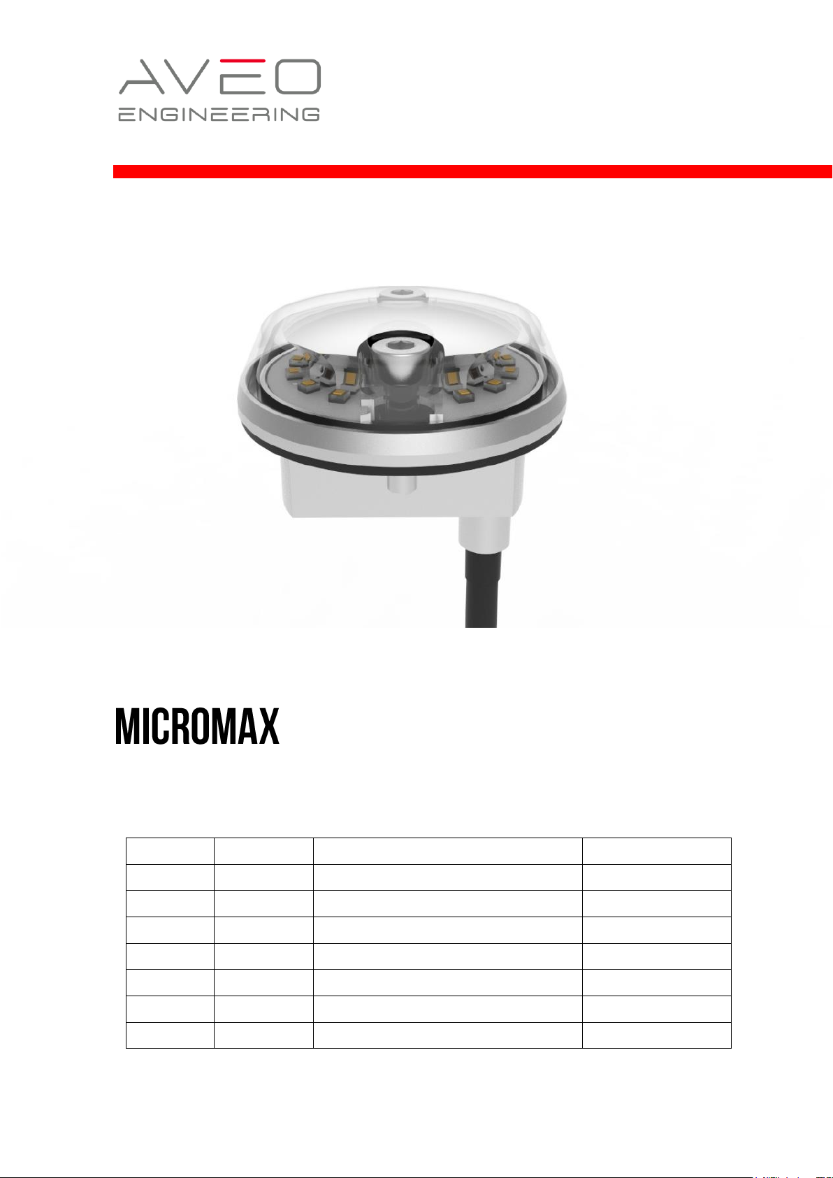
Fully D0-160 tested and weighing in at only 23 grams, MicroMax™ will help you comply with all the
tightening and future regulations around operating small UAVs/MiniDrones and ensure SAFETY is
included in your flight operations. Available in Red, White, NVIS White or even InfraRed, the patented
MicroMax™ provides a 360 degree arc of coverage. An amazing product from Aveo’s famous engineering
prowess, which has made it the world market leader in UAV lighting by a wide margin.
12 High brightness LEDs for ANTICOLLISION light coverage (360°)
Packed with 12 ultra high brightness CREE LEDs in RED, WHITE, NVIS WHITE or INFRARED color that
are the industry state-of-the-art in performance and output lumens, the MicroMax feature a significantly
lower footprint than competitor lights.
Low Profile/Small Diameter Strobe
An extremely lightweight, aerodynamic and low-profile
design make this the light of choice for any aircraft
requiring a rear coverage light due to wingtip light
coverage zone limits.
No separate strobe power box needed
Aveo pioneered the no external power supply design from its inception in the industry and the copycats
have yet to match our exclusive circuitry. Quite simply the lowest weight solution you can get, in 9 to 32
volt input range too!
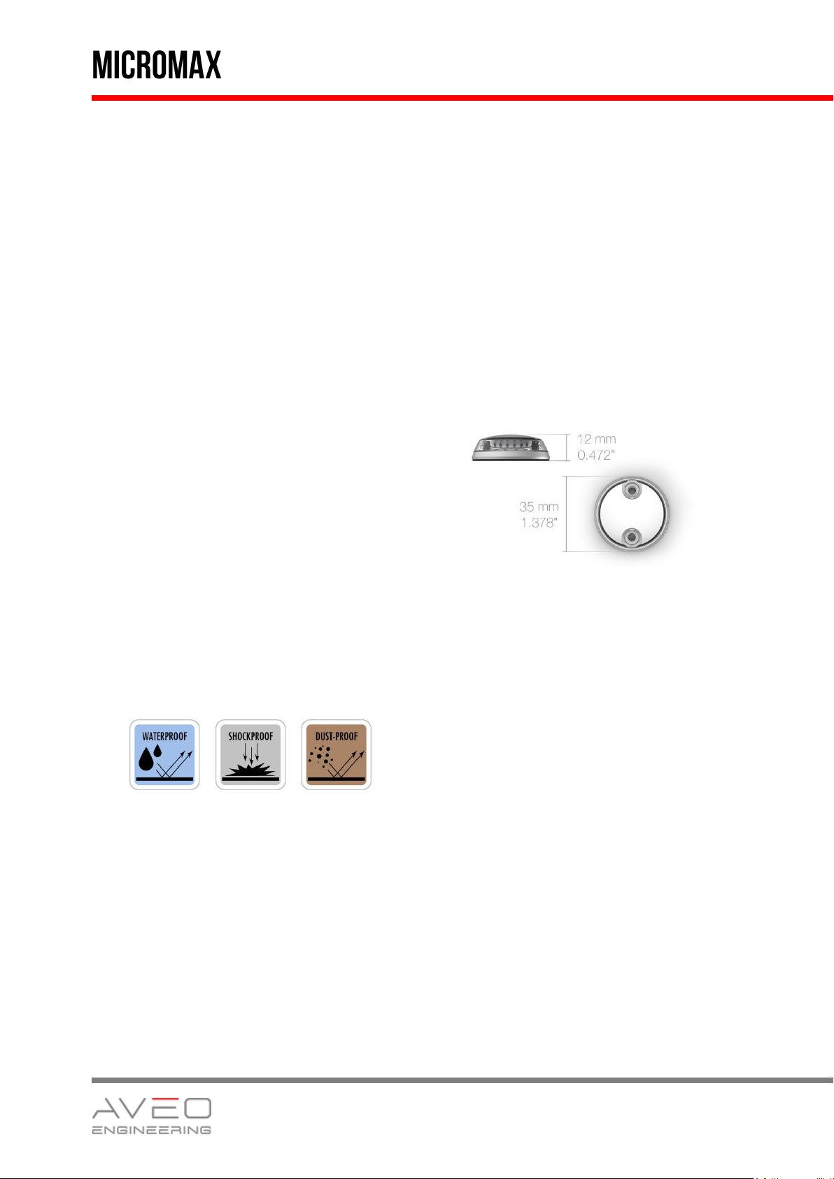
Waterproof / Shockproof / Dust-proof
2
Page 3
Installation Manual
Valid from: 01/Oct/2017
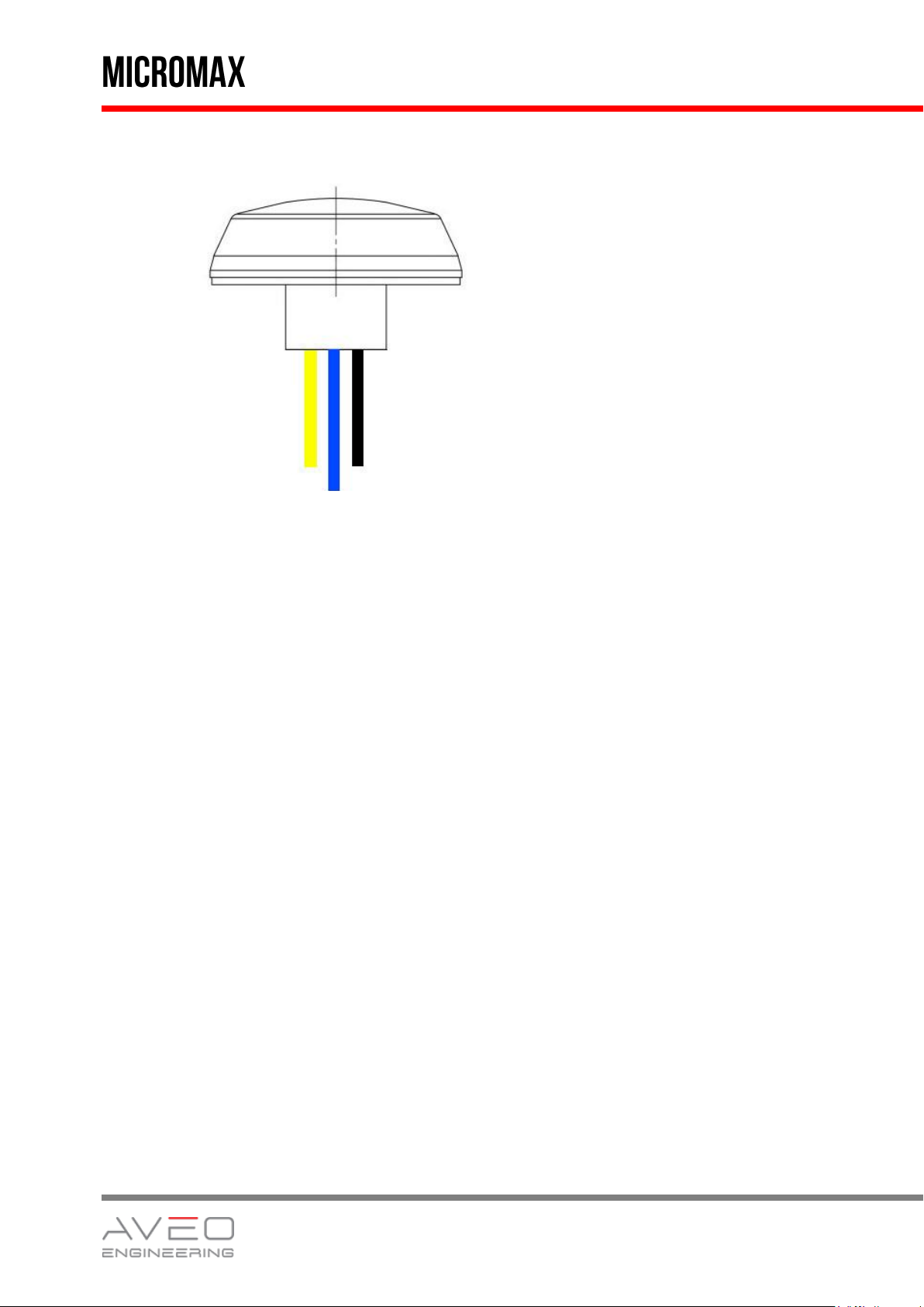
YELLOW
Power Input
AWG 22
BLACK
Power Return
AWG 22
BLUE
Synchro
AWG 22
2. WIRING DIAGRAM
Power Input - YELLOW - positive position power supply line
Power Return - BLACK - negative common power supply line (ground)
Synchronisation - BLUE - synchronisation line
3. TECHNICAL SPECIFICATION
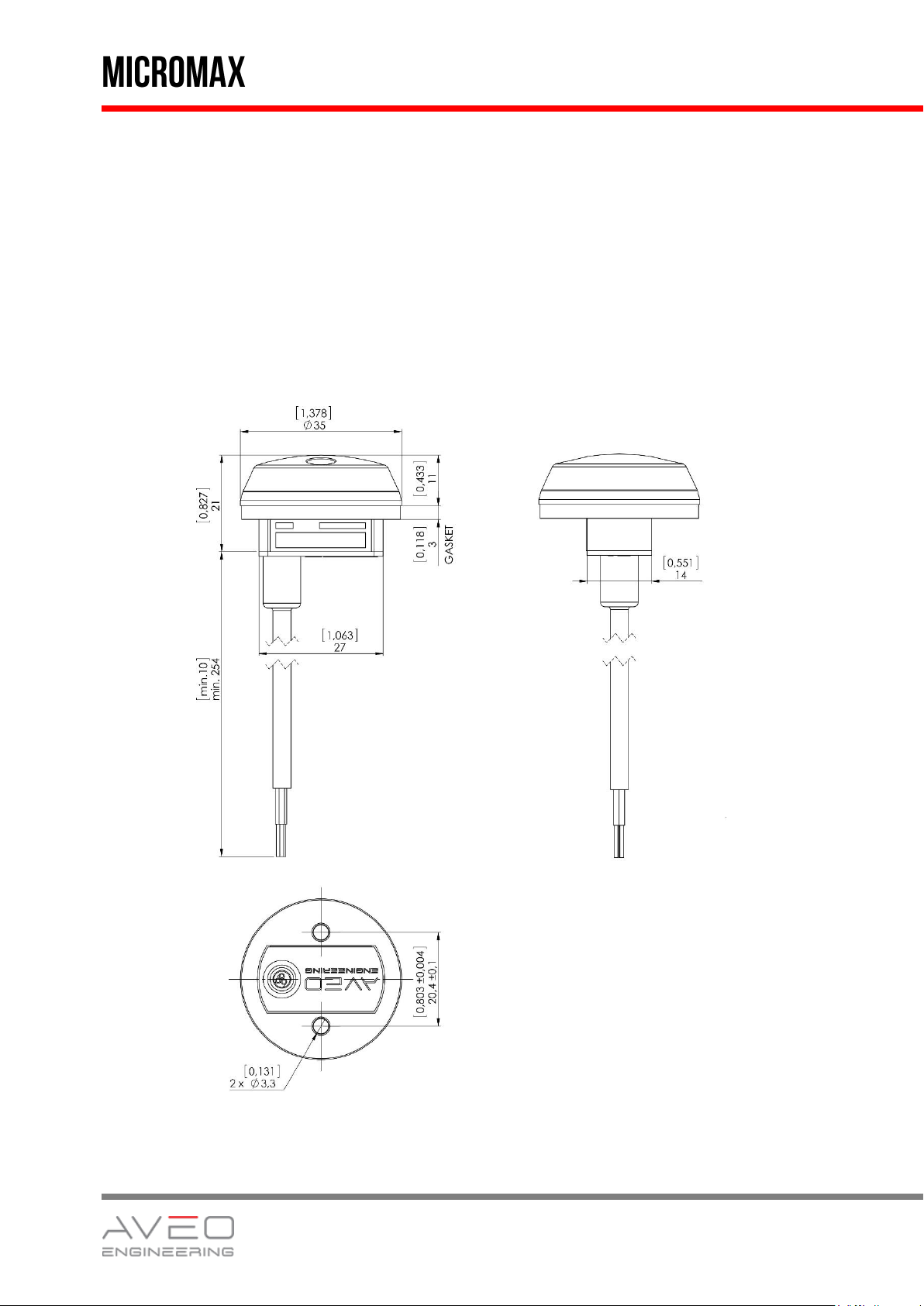
Dimensions: see section 4.Technical drawing
Weight: 23 g / 0.81 oz
Operating Voltage Range: 9 – 32V DC
Red LEDs version:
Output power: 6W (peak)
Input current: 0.27A @28V (peak)
0.50A @14V (peak)
White LEDs version:
Output power: 7,8W (peak)
Input current: 0.35A @28V (peak)
Repetition Flash Rate of Strobe: 50 cycles per minute
Recommended size of mounting screw: M3, stainless steel recommended. Length
depends upon placement location on wing tips.
Supplied cable: AWG22, length of wires is 25 cm (10 inches)
Reverse polarity protection: Yes
Over-Voltage spike protection: 60V/1s
3
Page 4
Installation Manual
Valid from: 01/Oct/2017
Over-Voltage shut down: Yes, 33V
Under-Voltage protection: Yes, 8.5V
Operating temperature: -40°C to +85°C (-40°F to +185°F)
Over-Temperature protection: Yes
Waterproof Yes
Vibration-proof Yes
Shock-proof Yes
Dust-proof Yes
4. TECHNICAL DRAWING
[inches] millimetres
4
Page 5
Installation Manual
Valid from: 01/Oct/2017
5. TESTING THE FUNCTION OF MICROMAX
BEFORE INSTALLATION
All Aveo Aviation lights undergo rigorous testing prior to being released from our engineering
manufacturing department. This testing involves a burn-in time as well as other function testing. No light
is released for sale without undergoing this extensive operational testing.
When you receive the Aveo lights, and wish to test the function of the lights prior to installation on your
aircraft, please note the following:
1. Please review the written information that is enclosed in the packaging. Warranty information as
well as a cautionary note about power supply removal is enclosed with each package.
2. Remove the lights from the package. Note that there are three (3) wires coming from each light.
These wires are:
a. Black wire – Ground wire (negative lead)
b. Yellow wire – Anticollision light function wire (positive leads)
c. Blue wire – Synchronisation wire (positive leads)
3. Testing of the function of each light can be done with a regular 12V/5A dc power supply (not a
battery chargers). Connect the black wire to the ground (negative) leads of a power supply, then
connect the yellow wire to the positive (+) leads on the power supply. The strobe light should
light up. Connecting the blue wires from each Aveo strobe/anticollision light together (and not to
the ground or positive terminals on the battery) should result in flashing all lights at once. It
indicates that the synchronization feature is working properly.When installed on the aircraft, using
the aircraft’s power (14 or 28 volts), the lights will be at their maximum intensity.
After testing, the lights can be installed on the aircraft.
IMPORTANT NOTES:
1. Under no circumstances should any power supply other than a 9-32V DC, or a 12/24 volt battery
be used to test the lights. Do not use: Battery chargers, battery back-up power devices, or other
bench avionics testing methods to test the aviation lights. The lights are functional between 9
and 32 volts. Use of a battery charger or other power unit to test the lights will void the warranty
and may damage the lights.
2. All power supplies for existing strobe lights, flasher beacons, etc. are required to be removed
from the aircraft prior to the installation of the Aveo lights.
5
 Loading...