

Page 1
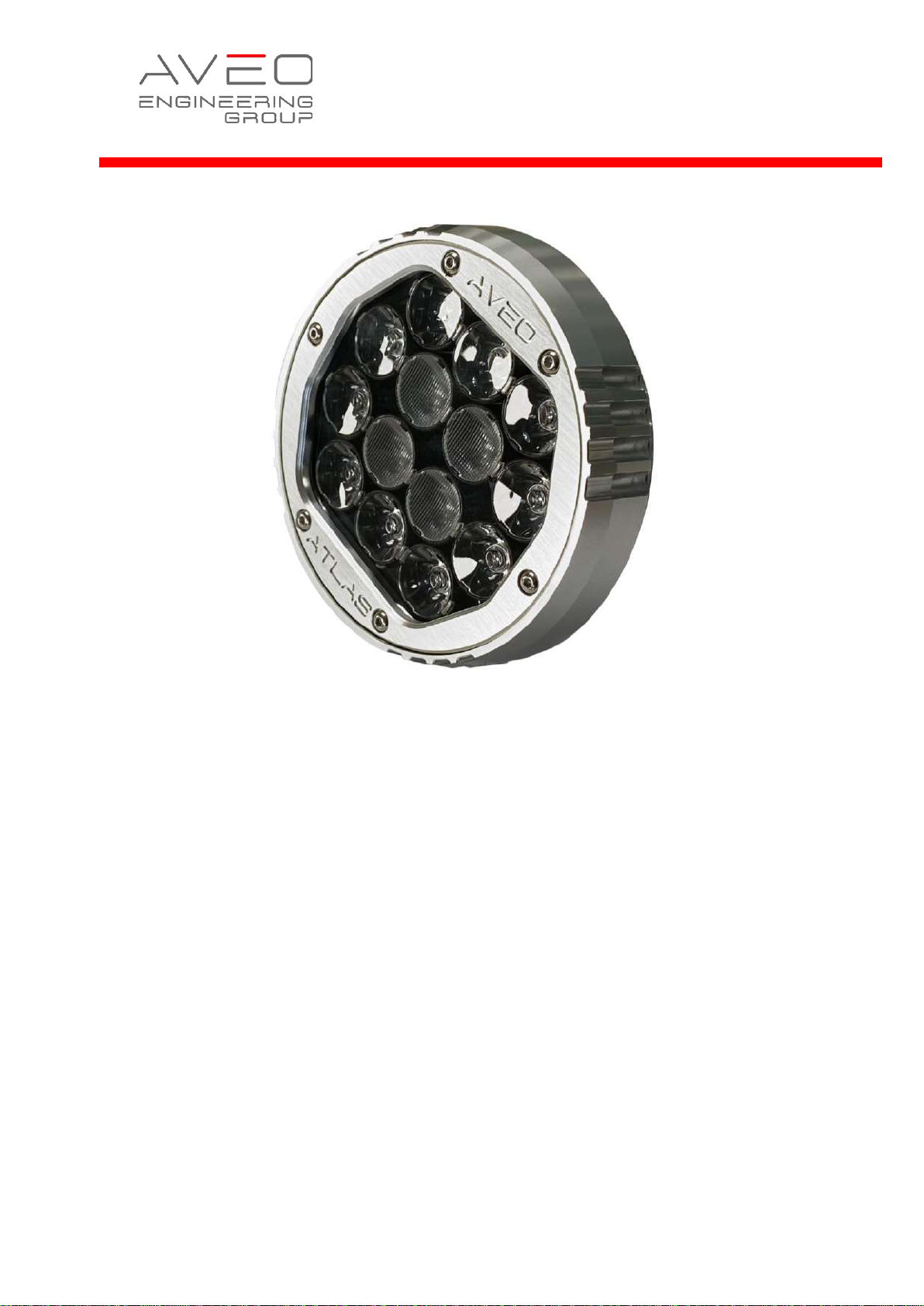
INSTALLATION MANUAL
Atlas NXT
AVE- AXT-IM
© Aveo Engineering Group, s.r.o. All rights reserved. The information contained within this document
must not be disclosed, copied or reproduced in whole or in part without prior written permission from
Aveo Engineering Group, s.r.o
Page 2
Page 2 of 17
Installation Manual
AVE-AXT-IM
Issue 01
TABLE OF CONTENTS
PART 0 DOCUMENT ADMINISTRATION ................................................... 3
0.1 DOCUMENT APPROVAL ............................................................................ 3
0.2 AMENDMENT RECORD PROCEDURE ............................................................. 4
0.3 AFFECTED PAGES PROCEDURE .................................................................. 4
PART 1 INSTALLATION DATA ................................................................. 5
1.1 PRODUCT INFO .................................................................................... 5
1.2 OPERATING INSTRUCTIONS ...................................................................... 5
1.3 INSTALLATION SCHEMATIC / WIRING DIAGRAM .............................................. 6
1.4 CONTROL & POWER INPUTS ..................................................................... 7
1.5 TECHNICAL SPECIFICATION ...................................................................... 7
1.6 TECHNICAL DRAWING ............................................................................ 9
1.7 WIRING CHART.................................................................................. 11
1.8 OPTIC SIMULATION ............................................................................. 12
1.9 EQUIPMENT LIMITATION........................................................................ 15
1.10 CARE AND CLEANING OF LIGHTS .............................................................. 15
1.11 TESTING THE LIGHTS BEFORE INSTALLATION ............................................... 15
1.12 CONTINUED AIRWORTHINESS INFORMATION ................................................ 16
1.13 ROHS COMPLIANCE STATEMENT .............................................................. 16
1.14 EU REACH REGULATION (EC) NO. 1907/2006 ......................................... 17
Page 3
Page 3 of 17
Installation Manual
AVE-AXT-IM
Issue 01
Part 0 Document Administration
0.1 Document Approval
This document has been established in accordance with an alternative procedure
to DOA approved under EASA AP429.
This installation manual is applicable for following part numbers:
• Atlas NXT - AVE-AXTTLFW-D01
• Atlas NXT – O holder - AVE-AXTTLFW-D02
• Atlas NXT – Q holder - AVE-AXTTLFW-D03
Compiled by: 02 Nov 2023
Petr Jaroš
Engineer, Aveo Engineering Group, s.r.o.
Approved by: 02 Nov 2023
Georg Hartl
Head of DO, Aveo Engineering Group, s.r.o.
Page 4
Page 4 of 17
Installation Manual
AVE-AXT-IM
Issue 01
0.2 Amendment Record Procedure
The master copy of this document shall be kept electronically as a read only
document under the control of Aveo Engineering Group, s.r.o. as Master Copy.
ALL amendments to this manual will initiate a raise of issue.
The original issue will be identified by “01”, and subsequent issues will be
numbered sequentially from 02 to 99 in Table 01 - Issue No. column.
ALL issues of this document will be approved by Head of DO.
0.3 Affected Pages Procedure
ALL pages affected by ANY raise of issue of this document will be listed in Table
01 - Affected Pages Column.
The reason(s) for EACH raise of issue and the description of respective change
will be provided in Table 01 - Details Column.
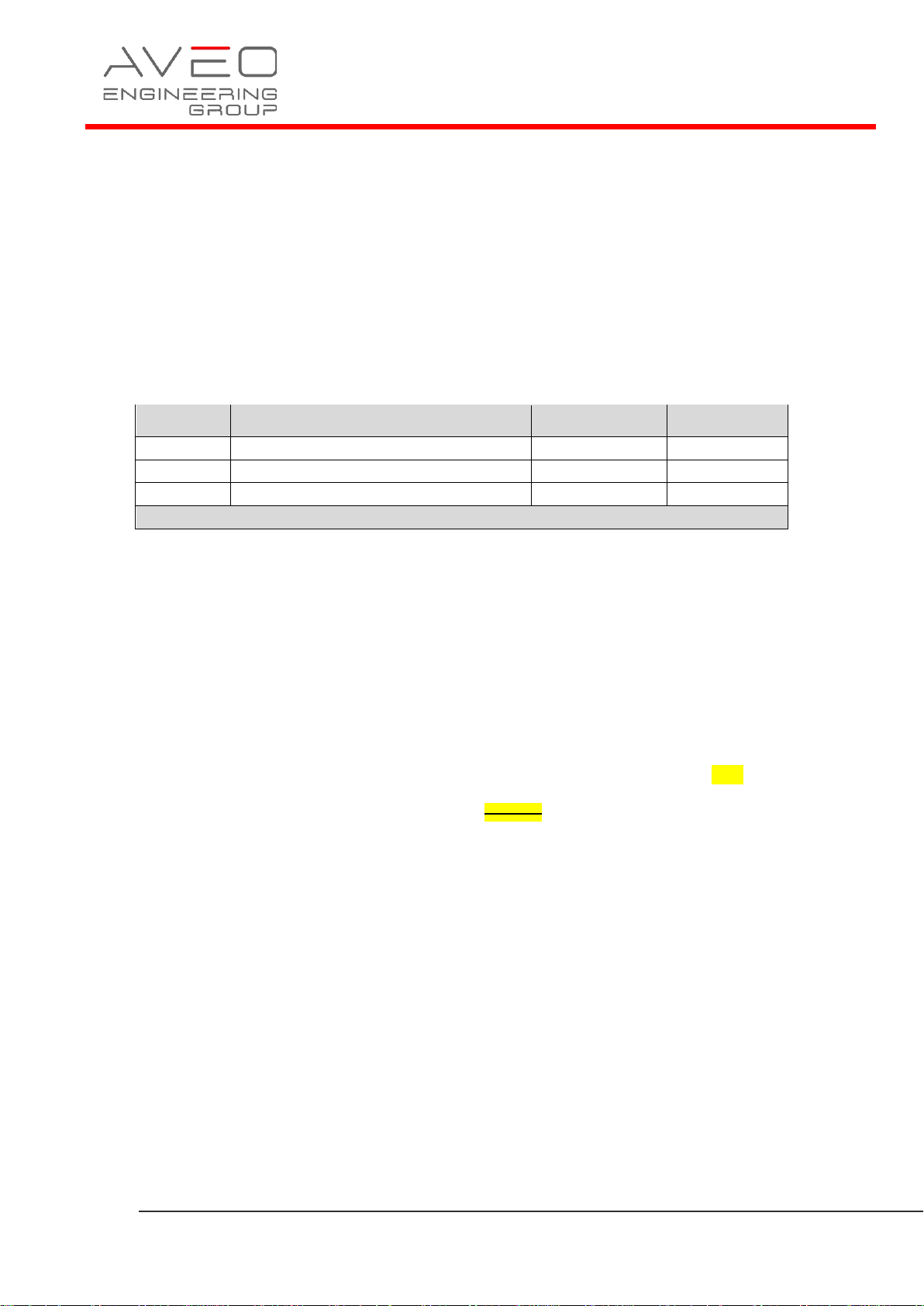
Changes from the previous issue are shown as follows:
a) new text is highlighted with yellow shading: new
b) deleted text is shown with yellow shading and a
strike through: deleted
Issue
No.
Details
Date of
issue
Affected
Pages
01
Initial Issue
17 Oct 2022
ALL
Table 01: Record of Document Amendments
Page 5
Page 5 of 17
Installation Manual
AVE-AXT-IM
Issue 01
Part 1 Installation data
1.1 Product Info
Atlas NXT™ is a high powered Landing and Taxi LED light used in GA and transport
category aircraft. It has been designed to be lightweight and with a low power draw
to meet the highest requirements of all certified aircraft.
• Atlas NXT - AVE-AXTTLFW-D01
• Atlas NXT – O holder - AVE-AXTTLFW-D02
• Atlas NXT – Q holder - AVE-AXTTLFW-D03
1.2 Operating Instructions
When installed on the aircraft, using the aircraft’s power (14 volts or 28 volts), the
light will be at its maximum intensity.
Operating Voltage range is +9…+36VDC.
Page 6
Page 6 of 17
Installation Manual
AVE-AXT-IM
Issue 01
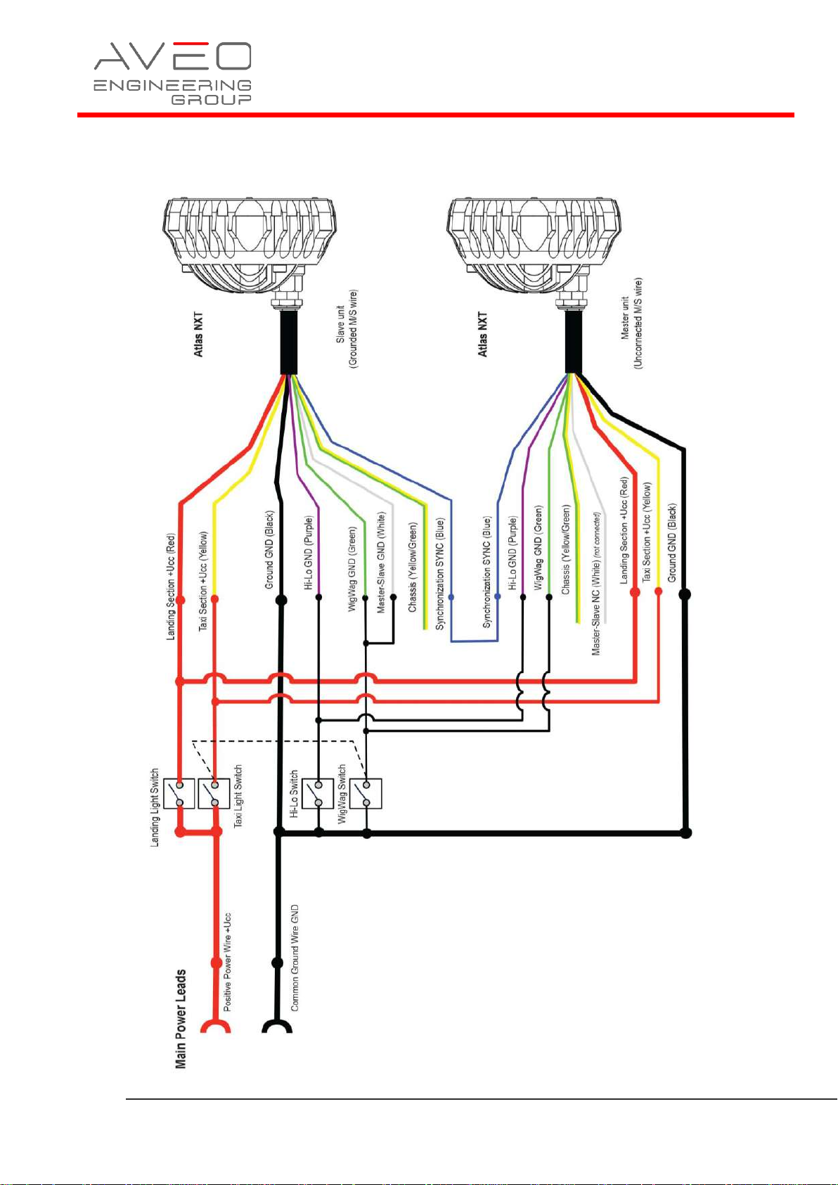
1.3 Installation Schematic / Wiring Diagram
Page 7
Page 7 of 17
Installation Manual
AVE-AXT-IM
Issue 01
1.4 Control & Power Inputs
RED Landing (AWG20)
YELLOW Taxi (AWG20)
BLACK GND (AWG20)
GREEN/YELLOW Chassis (AWG20)
WHITE Master/Slave (AWG24)
BLUE Synchro (AWG24)
VIOLET Hi/Lo (AWG24)
GREEN WigWag (AWG24)
Length: 300 mm / 11.8”
1.5 Technical Specification
Light characteristics: Multimode Light (Landing, Taxi, WigWag, Hi/Lo)
Voltage range: 9-36VDC
Voltage protection: a. Transcient voltage: 2 seconds +80VDC
b. Over-voltage lockout: +36VDC, not less
Performance:
Landing: Input current: 2.5A @14VDC, 1.3A @28VDC
Input power: 35W @14VDC, 36.4W @28VDC
Taxi: Input current: 1A @14VDC, 0.55A @28VDC
Input power: 14W @14VDC, 15.4W @28VDC
Chromaticity: Cool White
Ambient temperature: -55°C...+85°C / -67°F...+185°F
Overheat protection: Yes
Wiring: See section 1.3
Useful life: not less than 15.000 aircraft flight hours
Weight:
AVE-AXTTLFW-D01 323 g / 0.71 lb
AVE-AXTTLFW-D02 359 g / 0.79 lb
AVE-AXTTLFW-D03 344 g / 0.76 lb
Page 8
Page 8 of 17
Installation Manual
AVE-AXT-IM
Issue 01
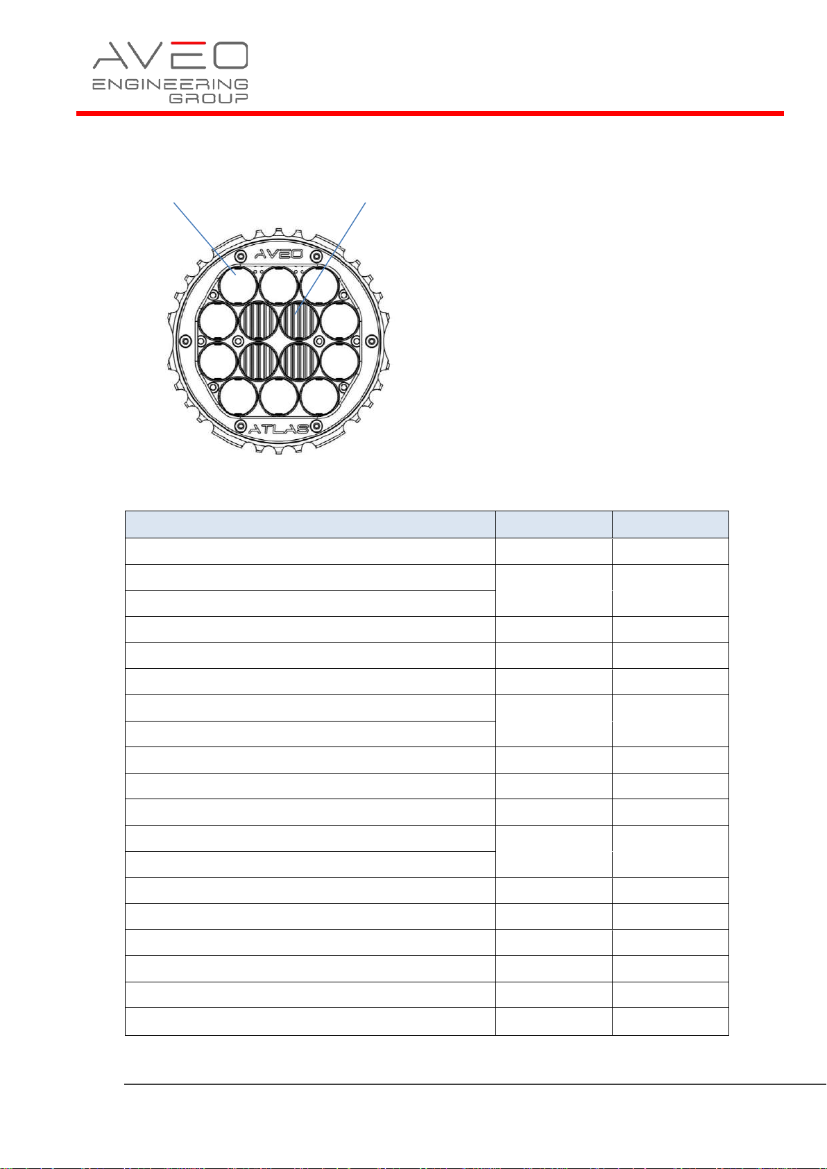
Viewing Angle:
Landing Lens: 9° Taxi Lens: 12° x 30°
Environment
Section
Category
Temperature / Altitude
4
F2
Temperature Variation
5
A
Humidity 6 C
Operational Shock and Crash Safety
7
B
Vibration
8
U, curves G
Explosive Atmosphere
9
H
Waterproofness
10
R
Fluids Susceptibility
11
F
Sand and dust
12
D
Fungus
13
F
Salt Spray
14
T
Magnetics Effects
15
Z
Power Input
16
Z
Voltage Spike
17
A
Audio Freq. Conducted Susceptibility
18
Z
Induced Signal Susceptibility
19
ZC
Radiated and Conducted Susceptibility
20
TT
Radiated and Conducted Emissions
21
B
Icing
24
A and C
Page 9
Page 9 of 17
Installation Manual
AVE-AXT-IM
Issue 01
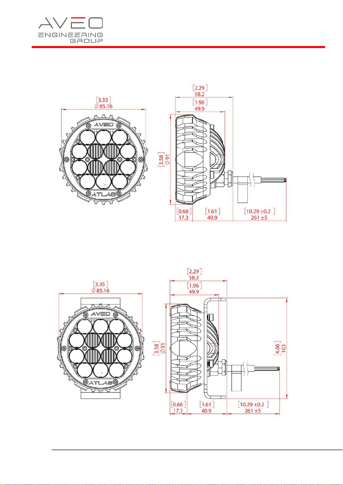
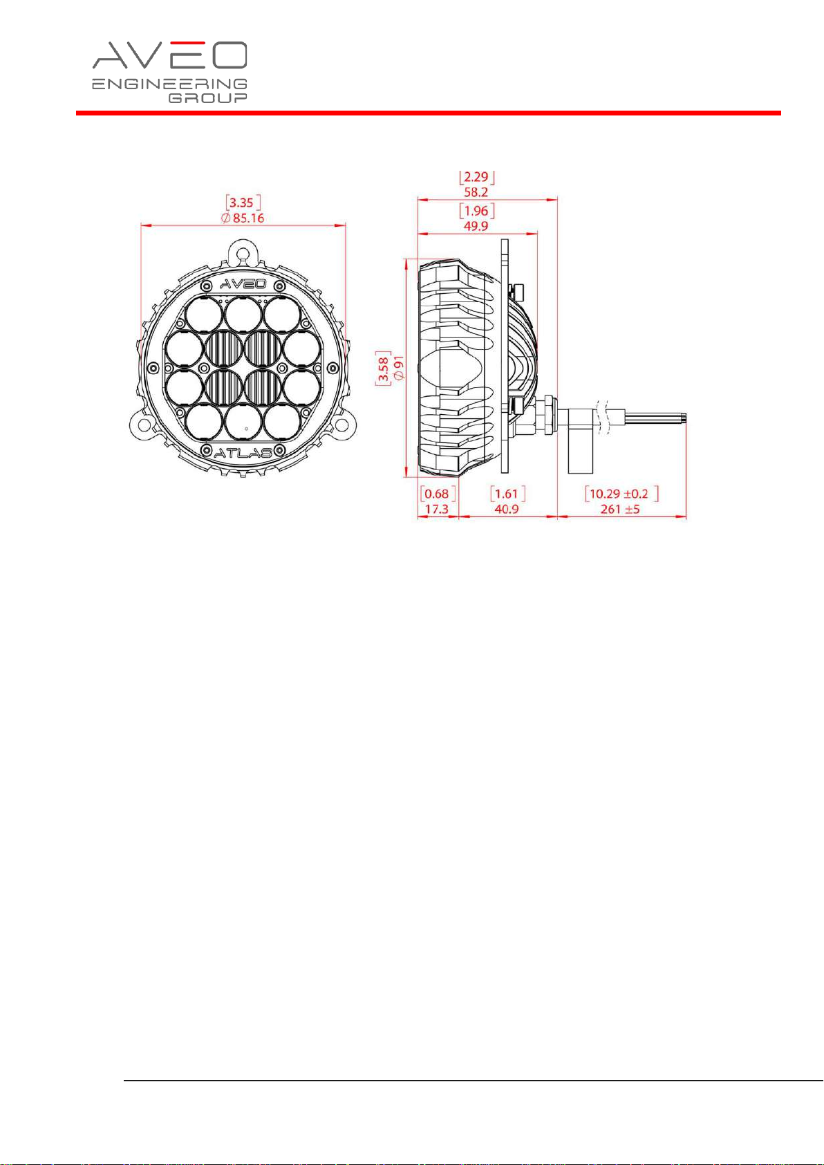
1.6 Technical Drawing
AVE-AXTTLFW-D01
AVE-AXTTLFW-D02
Page 10
Page 10 of 17
Installation Manual
AVE-AXT-IM
Issue 01
AVE-AXTTLFW-D03
*dimensions in [inches] / mm
Page 11
Page 11 of 17
Installation Manual
AVE-AXT-IM
Issue 01
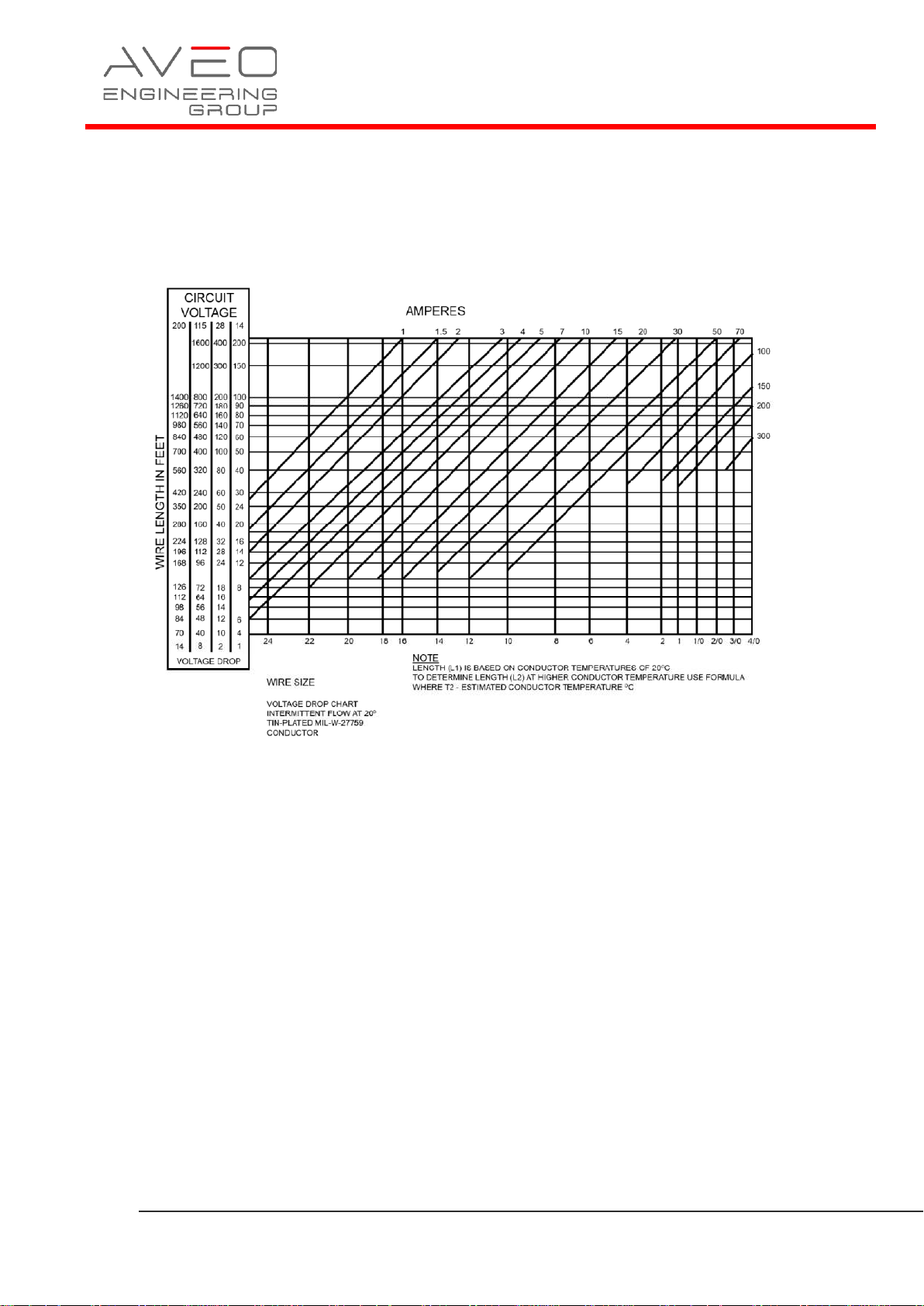
1.7 Wiring Chart
Use diagram below defining the wiring size depending on the current and the wire
length. Make sure you add up the current for all connected lights. If current is not
given, then divide the power by the voltage.
Page 12
Page 12 of 17
Installation Manual
AVE-AXT-IM
Issue 01
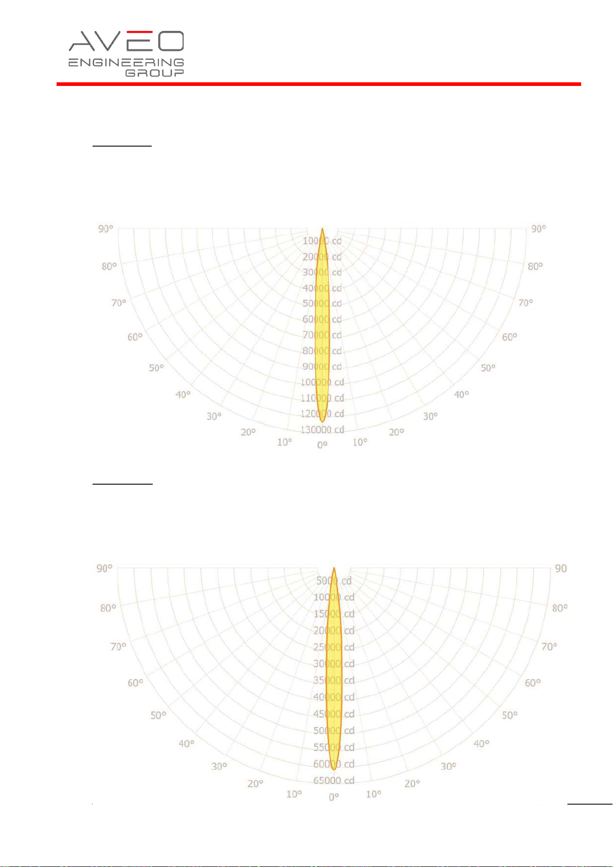
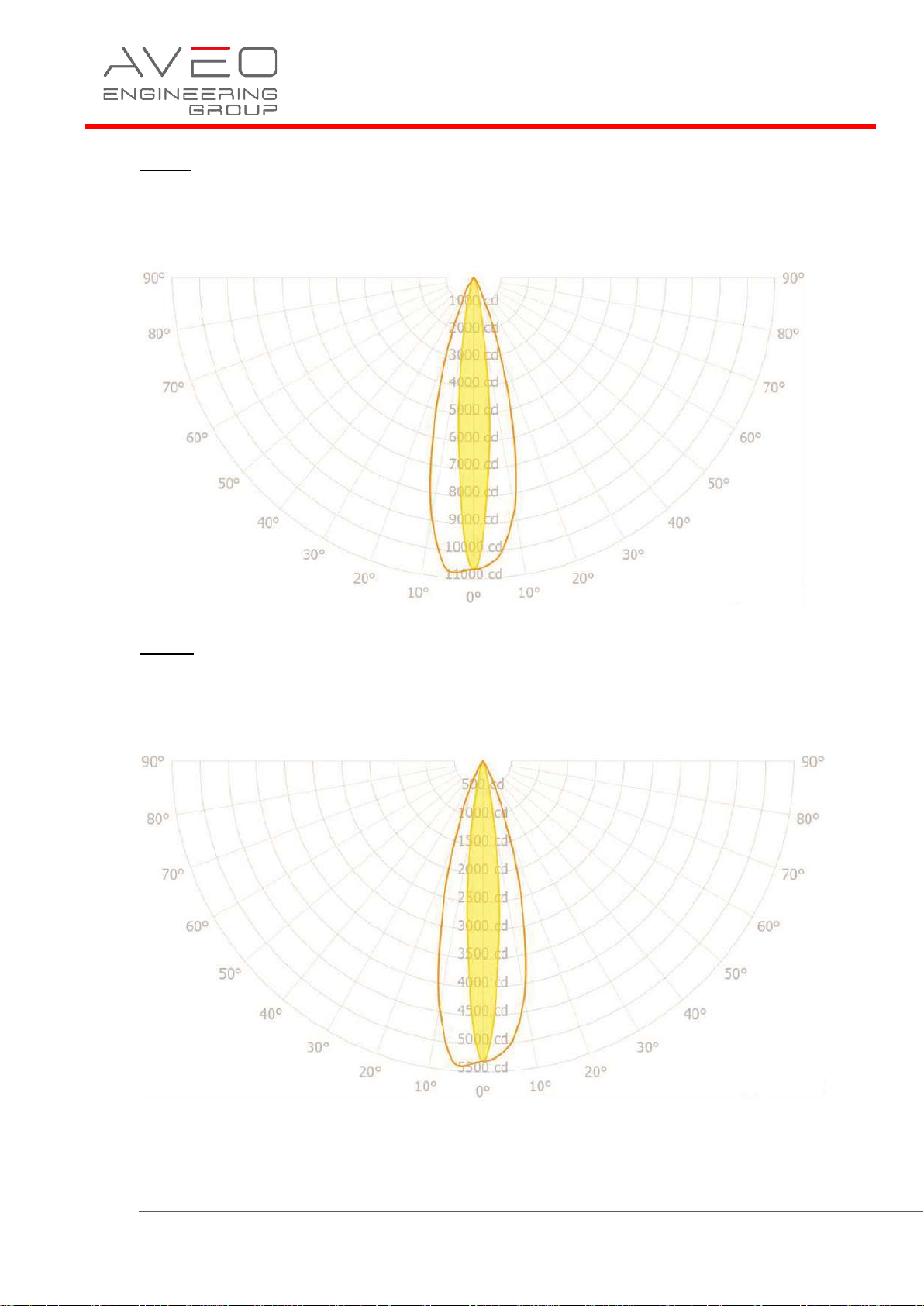
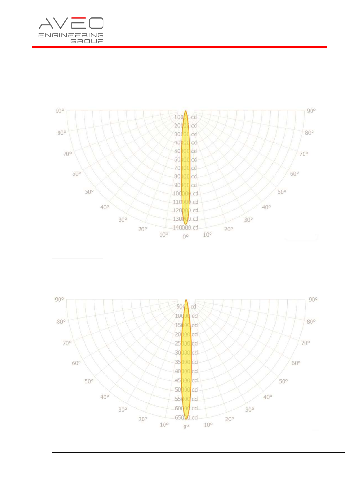
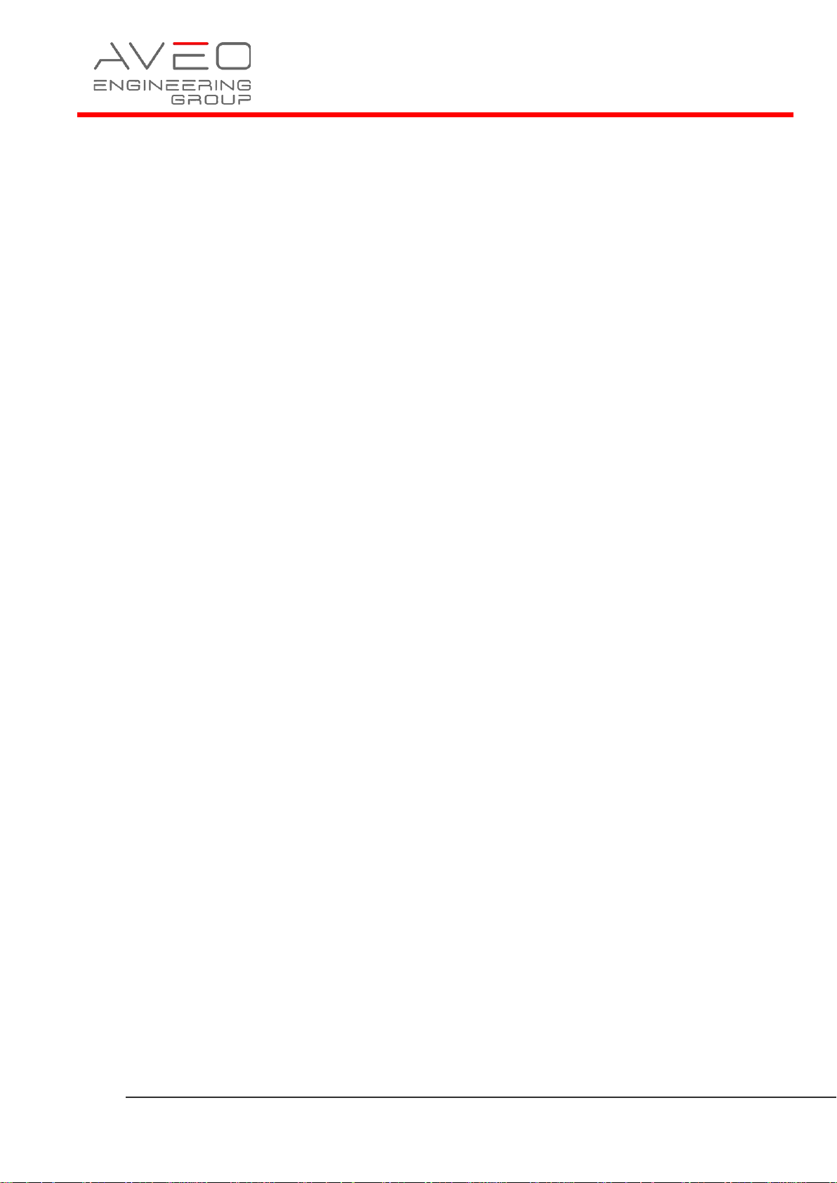
1.8 Optic Simulation
Landing Hi
123 000 cd
8.3° (at 50% of max light intensity)
18° (at 10% of max light intensity)
Landing Lo
60 800 cd
8.6° (at 50% of max light intensity)
18° (at 10% of max light intensity)
Page 13
Page 13 of 17
Installation Manual
AVE-AXT-IM
Issue 01
Taxi Hi
10 700 cd
12° x 30° (at 50% of max light intensity)
26° x 52° (at 10% of max light intensity)
Taxi Lo
5 390 cd
12° x 30° (at 50% of max light intensity)
26° x 52° (at 10% of max light intensity)
Page 14
Page 14 of 17
Installation Manual
AVE-AXT-IM
Issue 01
Both sections Hi
134 000 cd
8.5° x 9.2° (at 50% of max light intensity)
19° x 22° (at 10% of max light intensity)
Both sections Lo
64 900 cd
8.7° x 9.7° (at 50% of max light intensity)
20° x 24° (at 10% of max light intensity)
Page 15
Page 15 of 17
Installation Manual
AVE-AXT-IM
Issue 01
1.9 Equipment Limitation
Atlas NXT should only be powered by 9-36VDC
1.10 Care and Cleaning of Lights
Aveo Engineering Aviation Lights are factory polished and delivered as ready to
install on the aircraft.
If the lights need a deeper cleaning, they should be polished with a quality lamb’s
wool sheet that is suitable also for deeper polishing. Under no circumstances should
any petroleum based product be used to clean the lights.
1.11 Testing the Lights before Installation
All Aveo Aviation lights undergo rigorous testing prior to being released from
our engineering manufacturing department. This testing involves a burn-in time
as well as other function testing. No light is released for sale without undergoing
this extensive operational testing.
When you receive the Atlas NXT light, and wish to test the function of the
light prior to installation on your aircraft, please note the following:
1. Please review the written information that is enclosed in the packaging.
Warranty information as well as a cautionary note about power supply removal
is enclosed with each package.
2. Remove the light from the package. Note that there are 8 wires:
RED Landing (AWG20)
YELLOW Taxi (AWG20)
BLACK GND (AWG20)
GREEN/YELLOW Chassis (AWG20)
WHITE Master/Slave (AWG24)
BLUE Synchro (AWG24)
VIOLET Hi/Lo (AWG24)
GREEN WigWag (AWG24)
3. Testing of the function of the light can be done with a regular 12VDC
or 24VDC power supply (not a battery charger). Connect the ground wire
to black wire and then connect the power wire to the red wire. The
landing light section should start lighting. Disconnect the power wire.
Connect the power wire to the yellow wire. The taxi light section should
start lighting. When installed on the aircraft, using the aircraft’s power
(14VDC or 28VDC), the light will be at its maximum intensity.
After testing, the light can be installed on the aircraft.
Page 16
Page 16 of 17
Installation Manual
AVE-AXT-IM
Issue 01
IMPORTANT NOTES:
Under no circumstances should any power supply other than a 9-3
6VDC
, or a 12
or
24 volt battery be used to test the light. Do not use: Battery chargers,
battery back-up power devices, or other bench avionics testing methods to test
the aviation light. The light is functional between 18-36 volts. Use of a battery
charger or other power unit to test the light will void the warranty and may
damage the light.
If you have any questions about the installation of the lights, please refer to
our web site: www.aveoengineering.com
1.12 Continued Airworthiness Information
Circuit/Wiring Protection
Each Titan series light features a Negative Temperature Coefficient (NTC)
circuit that limits internal temperatures by attenuating operating current (with a
corresponding reduction of brightness) when internal temperatures reach a certain
threshold. This proprietary circuitry serves to protect the light itself, and
associated aircraft wiring, against a thermal runaway condition.
Periodic Inspection Procedure for Atlas NXT
The Atlas NXT light should always be checked for proper operation during
preflight. This procedural information is already provided in all general aviation
aircraft flight manuals.
The lights should be visually inspected for general condition, proper operation,
and correct installation at each annual and/or 100 hours inspection. In addition
refer to section 1.10 of installation manual for detailed cleaning instructions.
1.13 RoHS Compliance Statement
Scope
This statement clarifies Aveo Engineering’s compliance with European Union
Directive 2015/863/EU on the restriction of the use of certain hazardous substances
in electrical and electronic equipment ("RoHS") that took effect on June 4, 2015.
The RoHS Directive restricts the sale of electronic equipment containing certain
hazardous substances in the European Union including:
Cadmium(Cd): 0.01%
Mercury: 0.1%
Lead(Pb) : 0.1%
Hexavalent chromium (Cr6+) : 0.1%
Polybrominated biphenyls (PBB): 0.1 %;
Polybrominated diphenyl ethers (PBDE): 0.1 %
Bis(2-Ethylhexyl) phthalate (DEHP): 0.1% (added in 2015);
Benzyl butyl phthalate (BBP): 0.1% (added in 2015);
Dibutyl phthalate (DBP): 0.1% (added in 2015);
Diisobutyl phthalate (DIBP): 0.1% (added in 2015)
Page 17
Page 17 of 17
Installation Manual
AVE-AXT-IM
Issue 01
Compliance
Aveo Engineering certifies that all products sourced from manufacturing facilities
comply with the environmental standards set forth by the Directive 2015/863/EU,
recast amendment of RoHS Directive 2011/65/EU Article (4), and do not contain
any of the above-mentioned, 10 hazardous substances above the specified limits.
All products manufactured by Aveo Engineering are RoHS-compliant. With regards
to RoHS-2 CE marking, product packaging is labeled attesting conformity if
required.
References
Directive 2015/863/EU of the European Parliament and of the Council on the
restriction of the use of certain hazardous substances in electrical and electronic
equipment.
1.14 EU REACH Regulation (EC) No. 1907/2006
Aveo Engineering declares that no chemicals are produced and that none of the
chemicals used during the production process or needed for the product
maintenance or service, is listed on the current European Chemicals Agency’s
Candidate list of Substances of Very High Concern for Authorization.
 Loading...