

Page 1

www.avenview.com
1
5X5 VGA Matrix Switch with Audio and
Ethernet Support
Model #: SW-VGA-5X5
© 2012 Avenview Inc. All rights reserved.
The contents of this document are provided in connection with Avenview Inc. (“Avenview”) products. Avenview makes no representations or warranties with
respect to the accuracy or completeness of the contents of this publication and reserves the right to make changes to specifications and product descriptions at any
time without notice. No license, whether express, implied, or otherwise, to any intellectual property rights is granted by this publication. Except as set forth in
Avenview Standard Terms and Conditions of Sale, Avenview assumes no liability whatsoever, and disclaims any express or implied warranty, relating to its products
including, but not limited to, the implied warranty of merchantability, fitness for a particular purpose, or infringement of any intellectual property right.
Reproduction of this manual, or parts thereof, in any form, without the express written permission of Avenview Inc. is strictly prohibited.
Page 2

www.avenview.com
2
Table of Contents
1 Section 1: Getting Started .............................................................................................................. 3
1.1 Important Safeguards ............................................................................................................ 3
1.2 Safety Instructions ................................................................................................................. 3
1.3 Regulatory Notices Federal Communications Commission (FCC) ......................................... 4
1.4 Introduction ........................................................................................................................... 4
1.5 Package Contents ................................................................................................................... 6
1.6 Before Installation.................................................................................................................. 6
1.7 Panel Description ................................................................................................................... 7
1.7.1 SW-VGA-5X5 .......................................................................................................................... 7
1.7.2 SW-VGA-5X5 Rear Panel ....................................................................................................... 7
1.8 Software Control via RS232 or Ethernet Port ........................................................................ 8
1. Setting Button ........................................................................................................................ 9
1.9 IR Remote Control ................................................................................................................ 15
1.10 Installation ........................................................................................................................... 17
2 Section 2: Specifications ............................................................................................................... 18
Page 3

www.avenview.com
3
1 Section 1: Getting Started
1.1 Important Safeguards
Please read all of these instructions carefully before you use the device. Save this manual for future
reference.
What the warranty does not cover
Any product, on which the serial number has been defaced, modified or removed.
Damage, deterioration or malfunction resulting from:
Accident, misuse, neglect, fire, water, lightning, or other acts of nature, unauthorized
product modification, or failure to follow instructions supplied with the product.
Repair or attempted repair by anyone not authorized by us.
Any damage of the product due to shipment.
Removal or installation of the product.
Causes external to the product, such as electric power fluctuation or failure.
Use of supplies or parts not meeting our specifications.
Normal wear and tear.
Any other causes which does not relate to a product defect.
Removal, installation, and set-up service charges.
1.2 Safety Instructions
The SW-VGA-5X5 VGA Matrix with Audio and Ethernet support has been tested for conformance to safety
regulations and requirements, and has been certified for international use. However, like all electronic
equipment’s, SW-VGA-5X5 should be used with care. Please read and follow the safety instructions to protect
yourself from possible injury and to minimize the risk of damage to the unit.
Do not dismantle the housing or modify the module.
Dismantling the housing or modifying the module may result in electrical shock or burn.
Refer all servicing to qualified service personnel.
Do not attempt to service this product yourself as opening or removing housing may expose you to
dangerous voltage or other hazards
Keep the module away from liquids.
Spillage into the housing may result in fire, electrical shock, or equipment damage. If an object or liquid
falls or spills on to the housing, unplug the module immediately.
Have the module checked by a qualified service engineer before using it again.
Do not use liquid or aerosol cleaners to clean this unit. Always unplug the power to the device before
cleaning.
Page 4

www.avenview.com
4
1.3 Regulatory Notices Federal Communications Commission (FCC)
This equipment has been tested and found to comply with Part 15 of the FCC rules. These limits are designed
to provide reasonable protection against harmful interference in a residential installation.
Any changes or modifications made to this equipment may void the user’s authority to operate this
equipment.
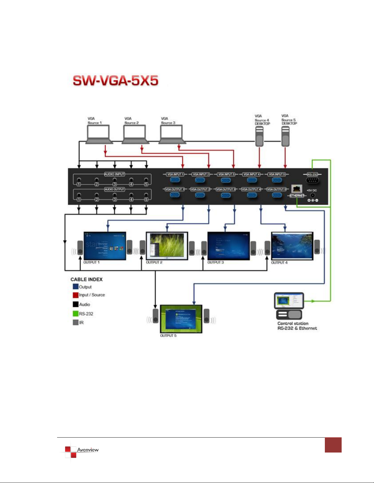
1.4 Introduction
This Avenview SW-VGA-5X5, 5X5 VGA Matrix Switch with Audio and Ethernet Support receives and amplifies
up to 5 VGA inputs, perfectly switches the desired input to the VGA equipped monitor or receiver. This matrix
enables the broadcast of multiple computers’ audio and video outputs to multiple displays. Any one of the
inputs can be broadcasted to any or all of the outputs without introducing noticeable video quality distortion.
The matrix switch supports VGA video bandwidth up to 400MHz and also supports YPbPr (component) signals.
The re-transmitted video quality is guaranteed and the longest transmission is up to 65 meters (210 feet).
Therefore, SW-VGA-5X5 offers the most convenient and cost effective means for swift switch of high quality
PC graphics and HDTV videos with crystal clear audio in the market. With equipped audio matrix, SW-VGA-5X5
is ready to be as YPbPr (Component) matrix with stereo audio and ideally for boardroom, showroom, and
exhibition. Through IR remote, RS-232 or front panel push button, the control of SW-VGA-5X5 becomes
versatile and easier.
- Broadcasts the audio and video outputs from five computers to five monitors and speakers
- Up to 5 Graphics/Video Inputs (appropriate adapters are required for Component))
- Supports video bandwidth up to 400 MHz
- Any one of the inputs can be broadcasted to any or all of the outputs
- Built-in video signal amplifier for up to 65m (210-ft) long transmission
- 3.5mm audio outputs to drive either speakers or earphones
- Multiple control by IR remote, push button, RS-232 control and Ethernet
- 1U rack mountable
Page 5
www.avenview.com
5
Page 6

www.avenview.com
6
1.5 Package Contents
Before you start the installation of the converter, please check the package contents.
- SW-VGA-5X5 x 1
- IR Remote Control x 1
- Power Adapter (+5VDC) x 1
- Mounting Brackets x 1
- Software CD x 1
- User’s Manual x 1
1.6 Before Installation
Put the product in an even and stable location. If the product falls down or drops, it may cause an
injury or malfunction.
Don’t place the product in too high temperature (over 50°C), too low temperature (under 0°C) or high
humidity.
Use the DC power adapter with correct specifications. If inappropriate power supply is used then it
may cause a fire.
Do not twist or pull by force ends of the optical cable. It can cause malfunction.
Page 7

www.avenview.com
7
1.7 Panel Description
1. Output Display LED
2. Input Display LED
3. Select Output
4. Select Input
5. IR Sensor
6. Power Indication LED
7. Ext. IR: IR Receiver
8. Analog Audio Inputs
9. Analog Audio Outputs
10. VGA Inputs
11. VGA Outputs
12. Ethernet Control Input
13. Serial Channel Control
14. Power Connector
15. ON/Off Switch
8 10 13
9 11 12 14 15
1.7.1 SW-VGA-5X5
1 2
3 4 56 7
1.7.2 SW-VGA-5X5 Rear Panel
Page 8

www.avenview.com
8
1.8 Software Control via RS232 or Ethernet Port
VGA input source selection area
VGA output port selection area
Status indicator
Software Control Menu
Page 9

www.avenview.com
9
1. Setting Button
1 Initial or any change to Ethernet settings, users MUST power cycle VGA matrix in order to
get the network settings effective!
2 Please notice that Ethernet control has a higher priority than RS-232. If RS-232 and Ethernet
controls come from 2 different hosts, commands may coincide and in this case, commands from
Ethernet will be effective immediately no matter whether commands from RS-232 are accurately sent
and executed!
Click Get button to read back device ID.
Click Set button to write device ID.
Click Rename button to open the String Table.
For Ethernet 1 group, users have to define Ethernet
properties through RS-232 for the matrix. All the
parameters for Ethernet have to be saved into the matrix
by clicking on Write To Device button.
In the Communication 2 group, users can choose the
control interface between matrix and PC host.
Page 10

www.avenview.com
10
In the GUI String Table group, click on “Rename” button and assign the captions for each input and
output port for easy recognition.
For example
Rename the Input1 to “Main PC”, Input2 to “Sub PC,” input3 to “PC-3,” … etc., and rename
output1 to “Conf. RM1,” output2 to “Main monitor,” output3 to “Lobby,” output4 to “Main
projector,” … etc.
2. Scan Button:
Serial Port Scan
Click Scan button, the machine will scan the all com
port and show them.
Select the RS232 serial port connected to the
machine. And set device ID 255 is for all device.
Only the same device id or 255 can get the
command you sent.
Click OK. Get the new status from the machine you
select.
3. Linkage Button:
Click Linkage button to read back all status.
Page 11

www.avenview.com
11
4. Open/Close Button:
Click this button to close or open COM port.
5. Mapping button:
Select All Output
Select set all output, and then select the source on main menu. You can quickly set all output to the
same source.
Unselect All Output
Release output selection.
Select Input1~5-Output
Select Input Source. Then select the output port icon.
For example
Select input source 1. Select output port 1 and 2. The video and audio will be sent to port 1 and 2.
Page 12

www.avenview.com
12
6. Fast Select button:
Click Fast select button. Quick setting.
Input one > Output Port one
Input two > Output Port two
…..
Click Fast select pull down menu.
Select Input Num-Output Num
Input source #1 > Output port #1
Input source #2 > Output port #2 …..
Select Input* - All Output
Send the same source to all output.
Page 13

www.avenview.com
13
7. Output Port:
Pull down menu and select which source to be sent to this output port.
One by one setting
On main menu screen
First select input source. Then select the output ports which you want to
send the video and audio from this source. When you select the input
source, the source will change to gray. When you select the output port
one by one, the selected output port will change to gray.
The linking line will change to yellow.
Group setting
First select output ports one by one. Then select the input source. The selected output ports change
the setting at the same time.
By using Terminal:
Baud rate: 9600
Data length: 8bit
Parity check: No
Stop bit: 1
Page 14

www.avenview.com
14
Command Set:
COMMAND
ACTION
COMMAND
ACTION
ST
System Status
VR
Firmware Version
A1
Output A selects Input 1
D1
Output D selects Input 1
A2
Output A selects Input 2
D2
Output D selects Input 2
A3
Output A selects Input 3
D3
Output D selects Input 3
A4
Output A selects Input 4
D4
Output D selects Input 4
A5
Output A selects Input 5
D5
Output D selects Input 5
B1
Output B selects Input 1
E1
Output E selects Input 1
B2
Output B selects Input 2
E2
Output E selects Input 2
B3
Output B selects Input 3
E3
Output E selects Input 3
B4
Output B selects Input 4
E4
Output E selects Input 4
B5
Output B selects Input 5
E5
Output E selects Input 5
C1
Output C selects Input 1
C2
Output C selects Input 2
C3
Output C selects Input 3
C4
Output C selects Input 4
C5
Output C selects Input 5
Page 15

www.avenview.com
15
1.9 IR Remote Control
INPUT 1
VGA input port #1
INPUT 2
VGA input port #2
INPUT 3
VGA input port #3
INPUT 4
VGA input port #4
INPUT 5
VGA input port #5
OUTPUT 1
VGA output port #1
OUTPUT 2
VGA output port #2
OUTPUT 3
VGA output port #3
OUTPUT 4
VGA output port #4
OUTPUT 5
VGA output port #5
Please push one of the INPUT buttons to choose which VGA input source you are going to setup. After that,
you can have multiple outputs playing the same content from the selected INPUT 1 – INPUT 5 by pushing the
corresponding OUTPUT buttons. The setting will be effective in a couple of seconds.
INPUT & OUTPUT MAPPING
Page 16

www.avenview.com
16
Page 17

www.avenview.com
17
1.10 Installation
To setup Avenview SW-VGA-5X5, follow these steps:
1. Connect VGA enable equipment’s to the outputs of SW-VGA-5X5.
2. Connect the VGA input sources to the inputs of SW-VGA-5X5.
3. Plug power adapter cable into 5V DC power jack.
4. Use IR Remote, Ethernet, RS-232 serial commands, or front panel push button to switch among
inputs.
Page 18

www.avenview.com
18
2 Section 2: Specifications
Item
Description
Units
SW-VGA-5X5
Unit Description
VGA Matrix Switch with Audio and Ethernet
Supported Input /
Output
VGA / Component
Video Bandwidth
400 MHz
Supported Resolutions
1080p 60, WUXGA (1920x1200 @ 60Hz)
Audio Support
Analog Stereo
Input
5 x VGA
5 x 3.5mm
1 x RS232
(Component through VGA to Component Adapter)
Output
5 x VGA
5 x 3.5mm
(Component through VGA to Component Adapter)
Input Selection
IR Remote / Push Button / RS232 Control / Ethernet
IR Remote Control
Electro-optical characteristics: = 25° / Carrier frequency: 36-40kHz
VGA Connector
HD-15 (15 pin D-sub female)
Audio Connector
3.5mm Earphone Jack for analog stereo audio
RS232 Connector
DE-9 (9-pin D-sub Female)
Dimensions (L x W x H)
17” x 3.8” x 1.7”
Power Supply
5V 4A DC
Power Consumption
13 Watt (max)
Environmental
Operating Temperature
32˚ ~ 104˚F (0˚ to 40˚C)
Storage Temperature
-4˚ ~ 140˚F (-20˚ ~ 60˚C)
Relative Humidity
20~90% RH (no condensation)
Page 19

www.avenview.com
19
Disclaimer
While every precaution has been taken in the preparation of this document, Avenview Inc. assumes no liability with respect to the
operation or use of Avenview hardware, software or other products and documentation described herein, for any act or omission of
Avenview concerning such products or this documentation, for any interruption of service, loss or interruption of business, loss of
anticipatory profits, or for punitive, incidental or consequential damages in connection with the furnishing, performance, or use of the
Avenview hardware, software, or other products and documentation provided herein.
Avenview Inc. reserves the right to make changes without further notice to a product or system described herein to improve reliability,
function or design. With respect to Avenview products which this document relates, Avenview disclaims all express or implied warranties
regarding such products, including but not limited to, the implied warranties of merchantability, fitness for a particular purpose, and
non-infringement.
 Loading...