

Page 1
www.avenview.com
1
4X4 HDMI 1.3 over CAT5
Matrix Switch with IR Pass-Through
© 2009 Avenview Inc. All rights reserved.
The contents of this document are provided in connection with Avenview Inc. (“Avenview”) products. Avenview makes no representations or warranties with
respect to the accuracy or completeness of the contents of this publication and reserves the right to make changes to specifications and product descriptions at any
time without notice. No license, whether express, implied, or otherwise, to any intellectual property rights is granted by this publication. Except as set forth in
Avenview Standard Terms and Conditions of Sale, Avenview assumes no liability whatsoever, and disclaims any express or implied warranty, relating to its products
including, but not limited to, the implied warranty of merchantability, fitness for a particular purpose, or infringement of any intellectual property right.
Reproduction of this manual, or parts thereof, in any form, without the express written permission of Avenview Inc. is strictly prohibited.
Page 2

www.avenview.com
2
Table of Contents
Section 1: Getting Started ...................................................................................................................... 3
1.1 Important Safeguards ............................................................................................................ 3
1.2 Safety Instructions ................................................................................................................. 3
1.3 Regulatory Notices Federal Communications Commission (FCC) ......................................... 4
1.4 Introduction ........................................................................................................................... 4
1.5 Package Contents ................................................................................................................... 6
1.6 Before Installation.................................................................................................................. 6
1.7 Panel Description ................................................................................................................... 7
1.7.1 SW-HDMI-C5-4X4 Front Panel ............................................................................................... 7
1.7.2 SW-HDMI-C5-4X4 Rear Panel ................................................................................................ 7
1.7.3 HDMI-C5SW-R ....................................................................................................................... 8
1.7.3 Dip Switch for EDID & Audio Settings (SW1 – SW4).............................................................. 9
1.7.4 SW Main Dip Switch for Firmware Update ........................................................................... 9
1.8 IR Control Patch ..................................................................................................................... 9
1.8.1 Supported IR Data Formats ................................................................................................. 11
1.9 Installation (SW-HDMI-C5-4X4) ........................................................................................... 12
1.10 Operation and IR Control ..................................................................................................... 12
1.10.1 Source Side ........................................................................................................................ 12
1.10.2 Display Side ....................................................................................................................... 14
1.11 RS232 Serial Port Control ..................................................................................................... 15
1.11.1RS232 Commands .............................................................................................................. 18
Section 2: Specifications ....................................................................................................................... 19
Page 3

www.avenview.com
3
Section 1: Getting Started
1.1 Important Safeguards
Please read all of these instructions carefully before you use the device. Save this manual for future
reference.
What the warranty does not cover
Any product, on which the serial number has been defaced, modified or removed.
Damage, deterioration or malfunction resulting from:
Accident, misuse, neglect, fire, water, lightning, or other acts of nature, unauthorized
product modification, or failure to follow instructions supplied with the product.
Repair or attempted repair by anyone not authorized by us.
Any damage of the product due to shipment.
Removal or installation of the product.
Causes external to the product, such as electric power fluctuation or failure.
Use of supplies or parts not meeting our specifications.
Normal wear and tear.
Any other causes which does not relate to a product defect.
Removal, installation, and set-up service charges.
1.2 Safety Instructions
The Avenview SW-HDMI-C5-4X4 HDMI 1.3 Matrix Switch over CAT5 has been tested for conformance to safety
regulations and requirements, and has been certified for international use. However, like all electronic
equipment’s, the SW-HDMI-C5-4X4 should be used with care. Read the following safety instructions to protect
yourself from possible injury and to minimize the risk of damage to the unit.
Do not dismantle the housing or modify the module.
Dismantling the housing or modifying the module may result in electrical shock or burn.
Refer all servicing to qualified service personnel.
Do not attempt to service this product yourself as opening or removing housing may expose you to
dangerous voltage or other hazards
Keep the module away from liquids.
Spillage into the housing may result in fire, electrical shock, or equipment damage. If an object or liquid
falls or spills on to the housing, unplug the module immediately.
Have the module checked by a qualified service engineer before using it again.
Do not use liquid or aerosol cleaners to clean this unit. Always unplug the power to the device before
cleaning.
Page 4

www.avenview.com
4
1.3 Regulatory Notices Federal Communications Commission (FCC)
This equipment has been tested and found to comply with Part 15 of the FCC rules. These limits are designed
to provide reasonable protection against harmful interference in a residential installation.
Any changes or modifications made to this equipment may void the user’s authority to operate this
equipment.
1.4 Introduction
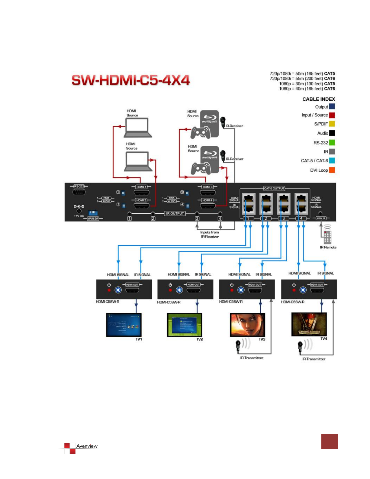
The Avenview SW-HDMI-C5-4X4, HDMI over CAT5 Matrix with IR Pass-through provides the most flexible and
cost effective solution in the market to route high definition video sources plus multi-channel (up to 7.1
channel) digital audio from any of the four HDMI sources to the remote displays at the same time. Through
low cost Cat-5/5e/6 LAN cables, not only high quality video and audio can be transmitted to the display sites,
but also users can switch among four HDMI sources using the push-in button or remote control. With single
power design at the source site, each remote module is easily installed without power supply. Furthermore,
the built-in IR extension function makes users at display site access the DVD player, PS3 or any HDMI
supported devices directly.
Page 5
www.avenview.com
5
Page 6

www.avenview.com
6
- Silicon Image chipset embedded for best quality, compatibility and reliability
- HDMI 1.3c compliant
- HDCP compliant
- Allows any source to be displayed on multiple displays at the same time
- Allows any HDMI display to view any HDMI source at any time
- Supports 7.1 channel digital audio
- Supports default HDMI EDID and learns the EDID of displays
- The matrix master can switch every output channels to any HDMI inputs by push-in button, IR remote
control, or RS-232 control
- Allows controlling local HDMI sources such as DVD and TiVo by attached IR extender from remote
receiver to matrix master
- Allows to control matrix master through IR remote control at remote receiver’s site
- Extends video signal up to 35m (115 feet) over CAT5e at 1080p and likely longer with better HDMI
source device, better grade HDMI display, and better quality solid CAT6 cable
- Easy installation with rack-mounting and wall-mounting designs for master and receiver respectively
- Fast response time – 2~5 seconds for channel
1.5 Package Contents
Before you start the installation of the converter, please check the package contents.
- SW-HDMI-C5-4X4 x 1
- HDMI-C5SW-R x 4
- IR Transmitter x 1
- IR Receiver x 1
- IR Remote Control x 1
- Rackmounting Ear x 2
- Power Adapter (+5VDC, 4A) x 1
- User’s Manual x 1
1.6 Before Installation
Put the product in an even and stable location. If the product falls down or drops, it may cause an
injury or malfunction.
Don’t place the product in too high temperature (over 50°C), too low temperature (under 0°C) or high
humidity.
Use the DC power adapter with correct specifications. If inappropriate power supply is used then it
may cause a fire.
Do not twist or pull by force ends of the optical cable. It can cause malfunction.
Page 7
www.avenview.com
7
1.7 Panel Description
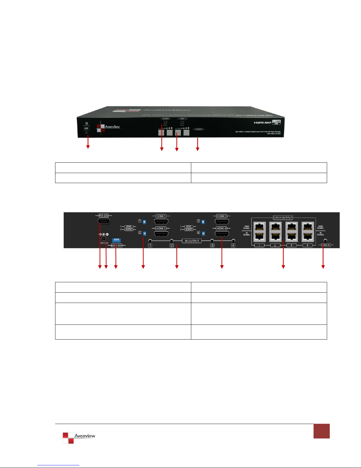
1. Power: Power Control
2. Seven Segment LED Indicators
3. Front Panel Push Buttons
4. IR Receiver
1. RS232
2. Power Jack
3. SW Main: DIP Switches
4. SW 1-4: DIP Switches
5. IR Pass Through 1 – 4: 3.5mm IR blaster
socket for individual HDMI Source
Control
6. HDMI Input 1 – 10: HDMI Inputs
7. Output Ports: 4 RJ45 Ports for each
Output Channel
8. IR Main: 3.5mm IR Blaster socket for
HDMI Source Control on all 8 Inputs
1.7.1 SW-HDMI-C5-4X4 Front Panel
1 3 4 5
1.7.2 SW-HDMI-C5-4X4 Rear Panel
1 2 3 4 5 6 7 8
Page 8
www.avenview.com
8
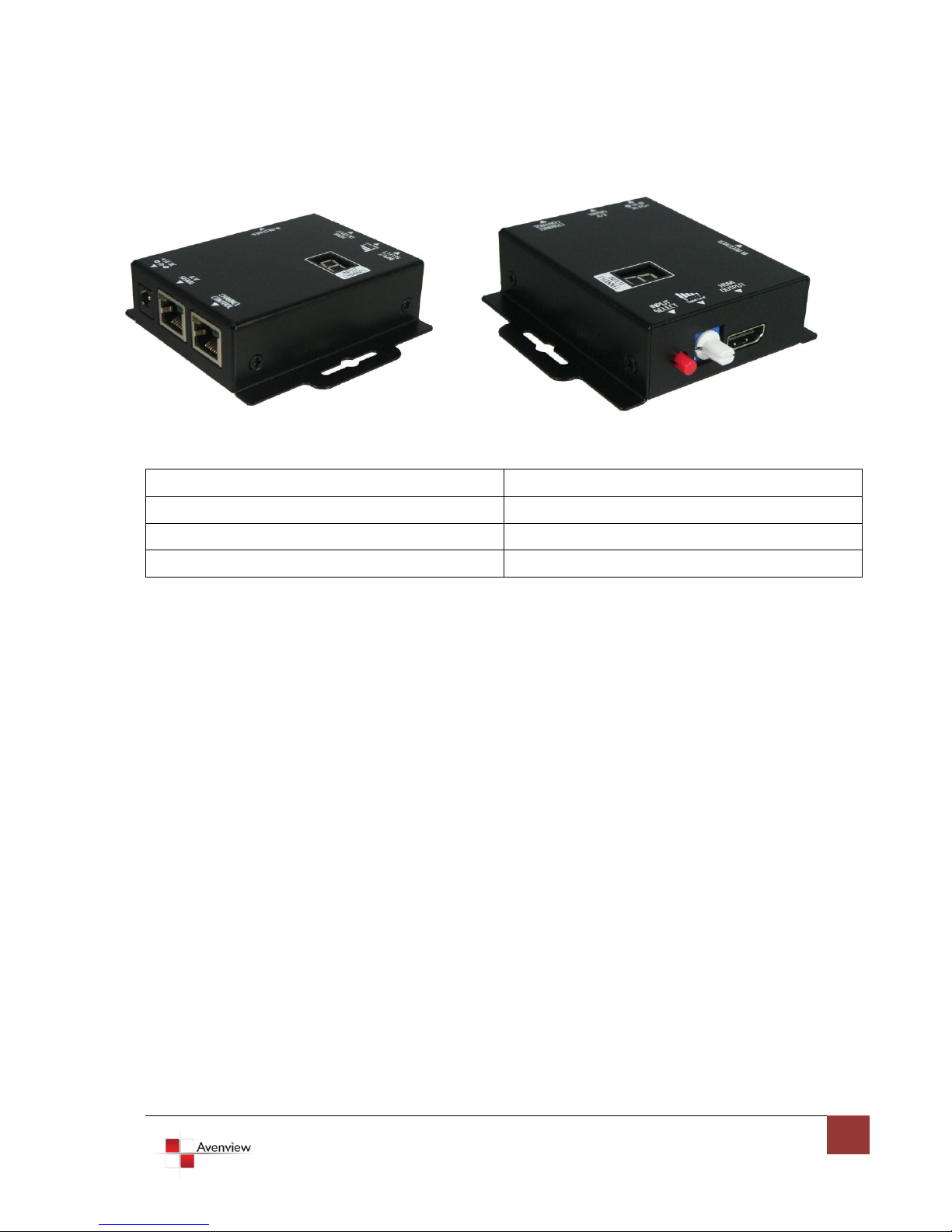
1.7.3 HDMI-C5SW-R
1. 5V DC Power jack
2. HDMI Signal
3. IR Signal
4. INPUT #
5. Input Select
6. EQ Level
7. HDMI OUT
8. IR Transmitter
Page 9
www.avenview.com
9
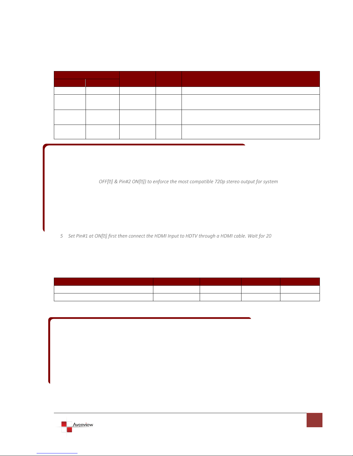
1.7.3 Dip Switch for EDID & Audio Settings (SW1 – SW4)
DIP Switch Position
Video
Audio
Description
PIN # 1
PIN # 2
OFF
OFF
1080p
Stereo1
Default Mode2: Up to 1080p & Stereo output.
OFF
ON
720p/1080i
Stereo
Safe Mode3: Forces system to output at 720p/1080i
with Stereo Audio.
ON
OFF
Bypass4
Bypass
EDID Learning Mode5: for learning EDID from the
display while playing any received HDMI Audio format.
ON
ON
Bypass
Stereo
EDID Learning & Stereo Mode: For learning EDID from
the display while enforcing stereo output.
DIP Switch Position
PIN # 1
PIN # 2
PIN # 3
PIN # 4
Normal Operation Mode6 RS232
OFF
OFF
OFF
OFF
Normal Operation Mode USB
OFF
OFF
OFF
ON
1 If the HDTV shows video but without audio, please try to set audio mode to stereo
6 Factory default for SW Main: Pin#1- OFF Pin#2- OFF Pin#3- OFF Pin#4- OFF PLEASE MAINTAIN
[5]. Set the DIP switch position to Normal Operation Mode.
2 Factory default: Pin#1-OFF[], Pin#2- OFF[] for 1080p with stereo.
3 If you encounter any unsolved audio/video output problem during system installation, please turn to
Safe Mode (Pin#1- check.
4 Bypass means the matrix will maintain playing the original format of HDMI signals in video and perhaps
audio. By setting at this mode, the users may encounter compatibility issue among different kinds of HDMI
sources and displays. If you cannot get the audio and/or video output normally at the system installation,
please change the DIP switch setting to default mode or even safe mode to verify the functionality of the
device.
seconds. The EDID learning procedure will be finished. If you want to learn the EDID from another HDTV, you
1.7.4 SW Main Dip Switch for Firmware Update
1.8 IR Control Patch
THIS SETTING AT ANYTIME FOR REGULAR USE!
7 Sequence for firmware update
[1]. Power off the SW-HDMI-C5-8X8.
[2]. Set the DIP switch position to Firmware Update Mode.
[3]. Power on the SW-HDMI-C5-8X8.
[4]. Power off the SW-HDMI-C5-8X8.
Page 10
www.avenview.com
10
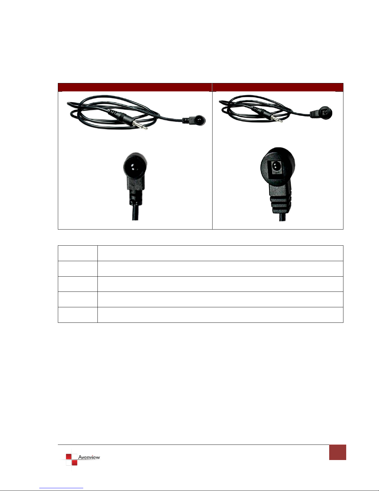
IR Transmitter Cable
IR Receiver Cable
IR Main
The default location for IR emitter extension cable to transmit all IR command signals received
from any of the four remote receivers to all of the HDMI sources.
IR1
IR emitter extension cable connected here can only transmit IR command signals from the
remote receivers that are setting at the input channel 1.
IR2
IR emitter extension cable connected here can only transmit IR command signals from the
remote receivers that are setting at the input channel 2.
IR3
IR emitter extension cable connected here can only transmit IR command signals from the
remote receivers that are setting at the input channel 3.
IR4
IR emitter extension cable connected here can only transmit IR command signals from the
remote receivers that are setting at the input channel 4.
Page 11

www.avenview.com
11
1.8.1 Supported IR Data Formats
Data Format
Suitable
Not Recommended
NEC
RC5
TOSHIBA MICOM CODE
GRUNDIG CODE
SONY 12 BIT CODE
SONY 15 BIT CODE
SONY 20 BIT CODE
RCA CODE
RCM CODE
MATSHUSHITA CODE
MITSUBISHI CODE
ZENITH CODE
JVC CODE
M50560-001P
MN6125H
MN6125L
MN6014-C5D7
MN6014-C6D6
MC14457P
LC7464(AHEA)
GEMINI-CM
Page 12

www.avenview.com
12
1.9 Installation (SW-HDMI-C5-4X4)
To setup Avenview SW-HDMI-C5-4X4 follow these steps for connecting to a device:
1. Connect all sources to HDMI Inputs on the 4X4 HDMI over CAT5 Matrix Switch (SW-HDMI-C5-4X4)
2. Connect each DDC output on the SW-HDMI-C5-4X4 to respective DDC input on the remote receiver
HDMI-C5SW-R
3. Connect each TMDS output on the SW-HDMI-C5-4X4 to respective TMDS input on the remote
receiver HDMI-C5SW-R
4. Connect IR emitter cable to the SW-HDMI-C5-4X4 and direct the IR emitter to the build-in IR receiver
of the sources
5. Connect the +5V 6A DC power supply to the SW-HDMI-C5-4X4
6. Power on all HDMI sources
7. Power on the SW-HDMI-C5-4X4
1.10 Operation and IR Control
1.10.1 Source Side
1.10.1.1Method A: Push Button
Push the switch button on the front panel, the source will be sequentially changed.
(+) increase (–) decrease
1.10.1.2Method B: IR Remote Control
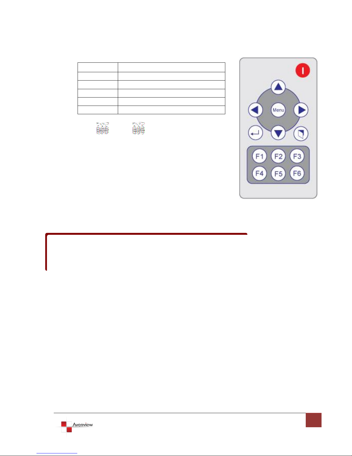
a. Please press F1 to F6, Enter ( ), and Exit ( ) button to enter IR control mode and decide which
output port to be controlled (see the table below), and wait a few seconds for the output port LED
to show the number of selected output port. Or you can use up () and down () button to enter
IR control mode and select the output port in ascending and descending order respectively. Decide
which output port to be controlled by pressing F1 to F4, and wait a few seconds for audio/video of
next channel coming out after the channel switch command is sent.
Page 13
www.avenview.com
13
F1
HDMI output #1
F2
HDMI output #2
F3
HDMI output #3
F4
HDMI output #4
Up ()
Switch output port in ascending order
Down ()
Switch output port in descending order
If the setting is correct, the corresponding LED will flash. If there is no response, please wait until the
b. Use or keys to select input source, and
wait a few seconds for audio/video of next channel coming out
after the channel switch command is sent.
LED stops flashing, and try again.
Left button to switch channels in ascending order (1, 2, 3, 4, 1, ...)
Right button to switch channels in descending order (1, 4, 3, 2, 1, …)
Page 14
www.avenview.com
14
1.10.2 Display Side
F1
HDMI output #1
F2
HDMI output #2
F3
HDMI output #3
F4
HDMI output #4
Up ()
Switch output port in ascending order
Down ()
Switch output port in descending order
1.10.2.1Method A: Push Button
Press the INPUT SELECT push-in button to switch the input source on the respective output port connected to
the matrix receiver in sequential order. The selected input source will be displayed on the LED of INPUT
CHANNEL.
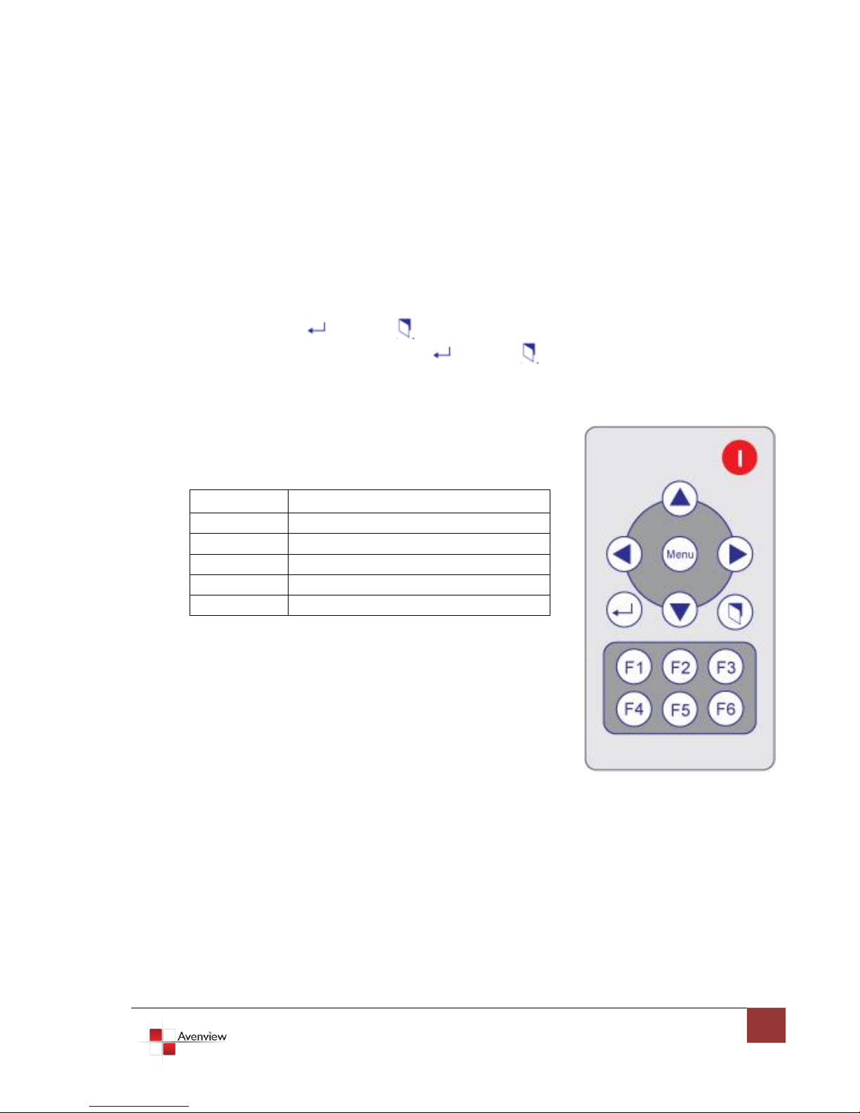
1.10.2.2Method B: IR Remote Control for Switching Input Channels
Please press F1 to F6, Enter ( ), and Exit ( ) button to enter IR control mode and decide which input
channel to be selected by pressing F1 to F6, Enter ( ), and Exit ( ) button, and wait a few seconds for
the input channel LED display to show the number of selected input source channel. Or you can use up
() and down () button to enter IR control mode and select the input channel in ascending and
descending order respectively.
1.10.2.2Method C: IR Remote Control for Controlling the HDMI Sources
Users can use the corresponding IR remote to control respective DVD player or any HDMI compliant devices
including SW-HDMI-C5-4X4 itself with IR control at any display site.
Page 15
www.avenview.com
15
1.11 RS232 Serial Port Control
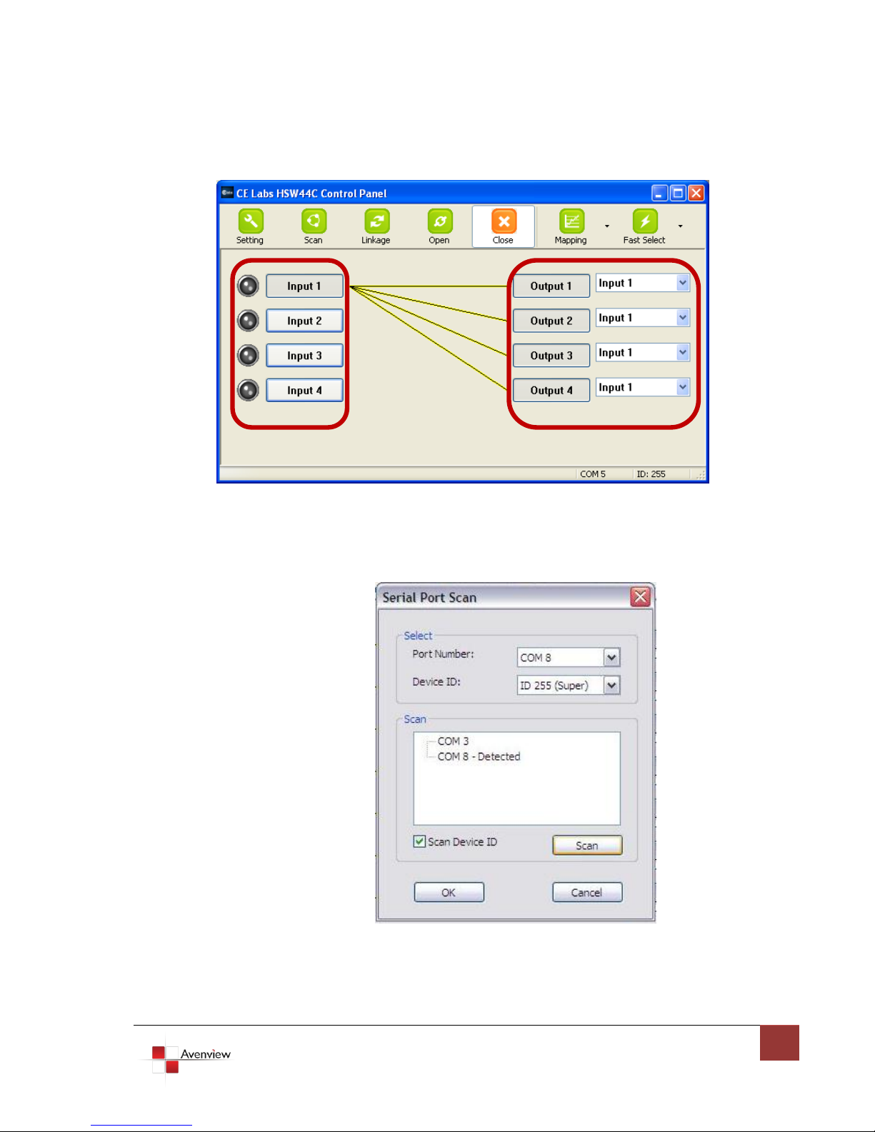
Scan: Press Scan button, the machine will scan the all com port and show them.
Select the RS232 serial port connected to the machine. And set device ID 255 is for all device.
Only the same device id or 255 can get the command you sent.
Press OK. Get the new status from the machine you select.
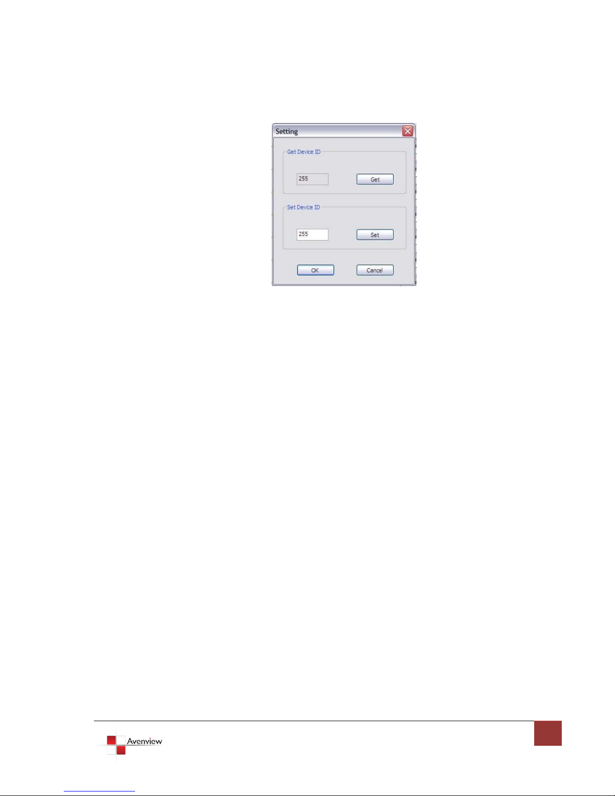
Setting:
Press Get button to read back device ID.
Page 16
www.avenview.com
16
Press Set button to write device ID.
Linkage: Press Linkage button to read back all status
Open / Close: Press this button to Close or Open COM Port.
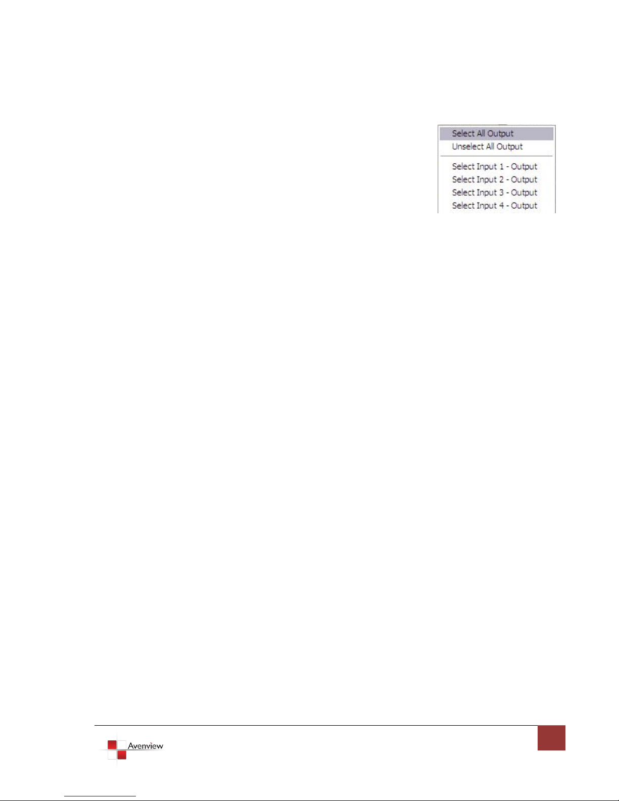
Mapping Button:
Select All Output:
Select “set all output”, and then select the source on main
menu. You can quickly set all output to the same source.
Unselect All Output:
Release output selection.
Select Input1~8-Output:
Select Input Source. Then select the output port icon.
For example:
Select input source 1. Then select output port one and two. The
video and audio will be sending to port one and two.
Page 17
www.avenview.com
17
Fast Select Button:
Press Fast select button. Quick setting.
Input one Output Port one
Input two Output Port two
…..
Press Fast select pull down menu.
Select Input Num-Output Num
Input source #1 Output port #1
Input source #2 Output port #2
…..
Select Input* - All Output
Send the same source to all output.
Output Port:
Pull down menu and select which source to be sent to this output port.
One by one setting
On main menu screen.
First select input source. Then select the output ports which you want to
send the video and audio from this source. When you select the input
source, the source will change to gray. When you select the output port
one by one, the selected output port will change to gray.
The linking line will change to yellow.
Group setting
First select output ports one by one. Then select the input source. The selected output ports change
the setting at the same time.
By using Terminal:
Baud rate: 9600
Data length: 8bit
Parity check: No
Stop bit: 1
Page 18
www.avenview.com
18
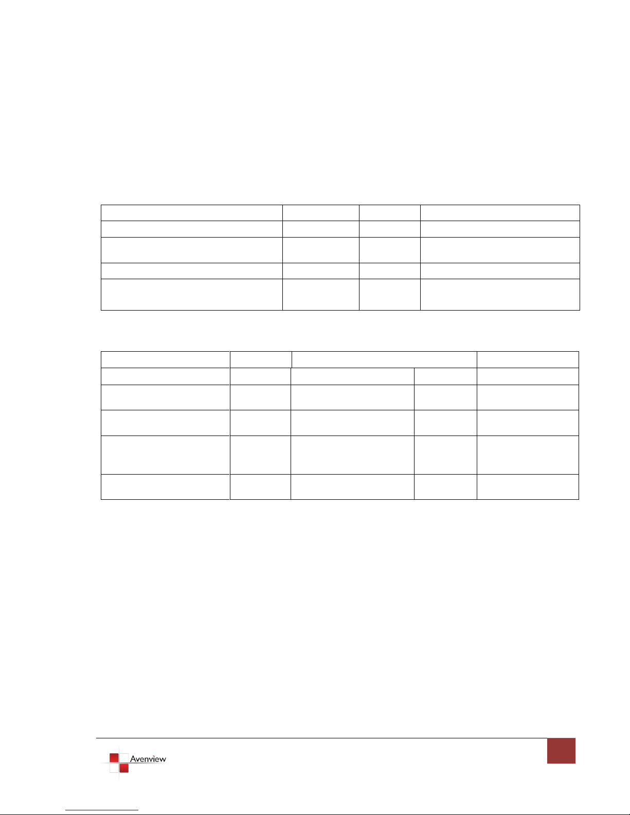
1.11.1RS232 Commands
Command Code
Response
Description
Data
Check SUM
ACK
SET
0x08 0x4d 0x41 0x51 0x44 0x05
*0x01~0xff
0x31~0x2f
0xaa
SET SW-HDMI-C5-4X4 Device ID
*0x01~0xff
0x0c 0x4d 0x41 0x51 0x44
Device_Id 0x02 port1 port2 port3 port4
0x0c+…+port4
0xaa
Set SW-HDMI-C5-4X4 Source
Mapping of Output Port
Command Code
Response
Description
Data
Check SUM
Get Status
Check SUM
Status
0x05 0x4d 0x4f 0x44
0xe5
0xaa 0x06 0x4d 0x41 0x51
0x44
0x29
Get Device Type
(SW-HDMI-C5-4X4)
0x07 0x4d 0x41 0x53 0x57
0x04
0x43
0xaa 0x3 0x01~0xff
0x04~0x02
Get Device ID
0x08 0x4d 0x41 0x51 0x44
*0x01~0xFF 0x01
0x2e~0x2c
0xaa 0x06port2 port3
port1 port4
0x06 + port1~port4
Get Source Mapping
of Output Port
0x08 0x4d 0x41 0x51 0x44
*0x01~0xFF 0x04
0x30~0x2e
0xaa 0x08 0x56 0x33
0x2e 0x30 0x31 0x61
0x81
Software Version
V.3.01a
RS-232 transmission Format
Baud rate: 9600
Data bit: 8
Parity: None
Set Command
Status Command
Check sum:
Check sum = (Data value sum)%256 The check sum of response is not included 0xaa.
0x01 ~ 0xFF:
This data is device ID. The Device ID saved in the device, if the device ID of the controlled device is 0xff , the
device will ignore its own ID and carry out the commands.
Page 19
www.avenview.com
19
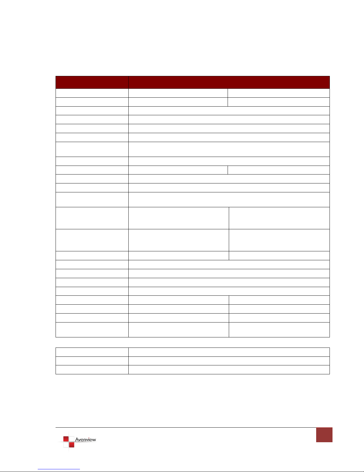
Section 2: Specifications
Item
Description
Units
SW-HDMI-C5-4X4
HDMI-C5SW-R
Unit Description
4X4 HDMI Matrix Switch over CAT5
HDMI 1.3 Receiver over CAT5
HDMI Compliance
HDMI 1.3c
HDCP Compliance
Yes
Video Bandwidth
Single Link 225 MHz (6.75Gbps)
Supported Resolutions
480i / 480p / 720p / 1080i / 1080p60
Resolution and Distance
Full HD: (1080p) ~ 35meter (115feet) (CAT5e) / 40meter (130feet) (CAT6)
HD: (720p/1080i) ~ 50meter (165feet) (CAT5e) / 55meter (180feet) (CAT6)
Audio Support
Surround Sound (up to 7.1 Ch.) or Stereo Digital Audio
Equalization
-
8 Level Digital Control
Input TMDS Signal
1.2 Volts (peak-to-peak)
Input DDC Signal
5 Volts (peak-to-peak, TTL)
ESD Protection
- Human body model — ±15kV (air-gap discharge) & ±8kV (contact discharge)
- Core chipset — ±8kV
Input
4 x HDMI
1 x RS232
1 x RJ45 TMDS
1 x RJ45 DDC
1 x IR Socket for IR Receiver
Output
4 x RJ45 HDMI Signal
4 x RJ45 IR Control
5 x IR Socket for IR Transmitter
1 x HDMI
HDMI Input Selection
Push Button / IR Remote / RS232
Push Button / IR Remote
HDMI Source Control
Through IR Control Path from IR Receiver
HDMI Connector
Type A (19 pin female)
RJ45 Connector
WE/SS 8P8C with 2 LED indicators
RS232 Connector
DE-9 (9-pin D-sub Female)
DIP Switch
Yes
-
Dimensions (L x W x H)
13” x 4.3” x 1.7”
3.3” x 3.5” x 1”
Power Supply
5V 6A DC
Most not required
Power Consumption
20 Watt (max)
1 Watt (max) / provided by
SW-HDMI-C5-4X4
Environmental
Operating Temperature
32˚ ~ 104˚F (0˚ to 40˚C)
Storage Temperature
-4˚ ~ 140˚F (-20˚ ~ 60˚C)
Relative Humidity
20~90% RH (no condensation)
Page 20

www.avenview.com
20
Notice
1. If the DVI or HDMI device requires the EDID information, please use EDID Reader/Writer to
retrieve and provide DVI/HDMI EDID information.
2. All HDMI over CAT5 transmission distances are measured using Belden 1583A CAT5e 125MHz
LAN cable and ASTRODESIGN Video Signal Generator VG-859C.3
3. The transmission length is largely affected by the type of LAN cables, the type of HDMI sources,
and the type of HDMI display. The testing result shows solid LAN cables (usually in bulk cable
300m or 1000ft form) can transmit a lot longer signals than stranded LAN cables (usually in
patch cord form). Shielded STP cables are better suit than unshielded UTP cables. A solid UTP
CAT5e cable shows longer transmission length than stranded STP CAT6 cable. For long extension
users, solid LAN cables are your only choice.
4. EIA/TIA-568-B termination (T568B) for LAN cables is recommended for better performance.
5. To reduce the interference among the unshielded twisted pairs of wires in LAN cable, you can use
shielded LAN cables to improve EMI problems, which is worsen in long transmission.
6. Because the quality of the LAN cables has the major effects in how long transmission distance
will be made and how good is the received display, the actual transmission length is subject to
your LAN cables. For resolution greater than 1080i or 1280x1024, a CAT6 cable is recommended.
7. If your HDMI display has multiple HDMI inputs, it is found that the first HDMI input
[HDMI input #1] generally can produce better transmission performance among all HDMI inputs.
Page 21
www.avenview.com
21
Disclaimer
While every precaution has been taken in the preparation of this document, Avenview Inc. assumes no liability with respect to the
operation or use of Avenview hardware, software or other products and documentation described herein, for any act or omission of
Avenview concerning such products or this documentation, for any interruption of service, loss or interruption of business, loss of
anticipatory profits, or for punitive, incidental or consequential damages in connection with the furnishing, performance, or use of the
Avenview hardware, software, or other products and documentation provided herein.
Avenview Inc. reserves the right to make changes without further notice to a product or system described herein to improve reliability,
function or design. With respect to Avenview products which this document relates, Avenview disclaims all express or implied warranties
regarding such products, including but not limited to, the implied warranties of merchantability, fitness for a particular purpose, and
non-infringement.
 Loading...