

Page 1
VIDEO WALLS VIDEO PROCESSORS
VIDEO MATRIX SWITCHES
EXTENDERS SPLITTERS WIRELESS
CABLES & ACCESSORIES
Control Your Video
© 2015 Avenview Inc. All rights reserved.
The contents of this document are provided in connection with Avenview Inc. (“Avenview”) products. Avenview makes no representations or
warranties with respect to the accuracy or completeness of the contents of this publication and reserves the right to make changes to specifications
and product descriptions at any time without notice. No license, whether express, implied, or otherwise, to any intellectual property rights is granted
by this publication. Except as set forth in Avenview Standard Terms and Conditions of Sale, Avenview assumes no liability whatsoever, and claims any
express or implied warranty, relating to its products are is strictly prohibited.
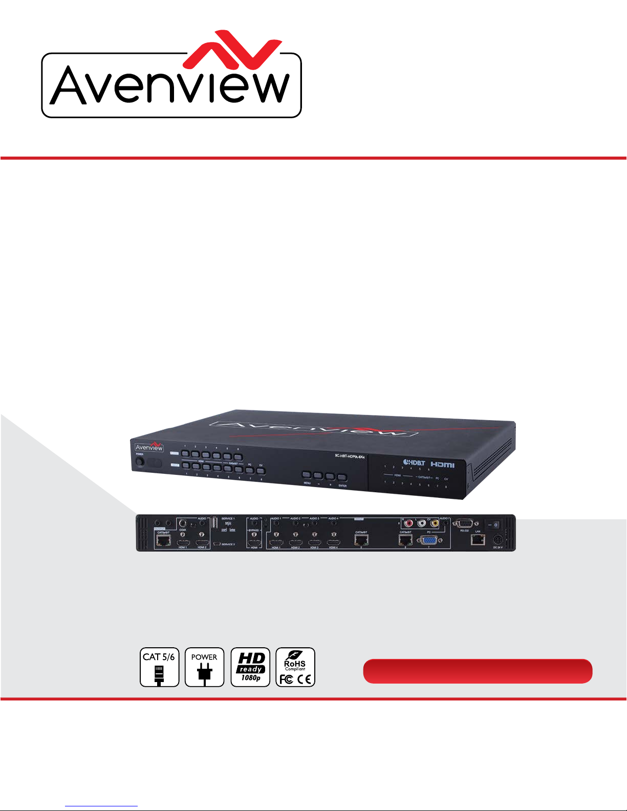
Model #: SC-HBT-HDMA-8X4
HBT-4K-C6-8X8E
Rev. 7.15
8x4 Multi Input Presentation switcher with
HDBaseT Support
Page 2

Page|2
www.avenview.com
TABLE OF CONTENTS
SECTION 1: GETTING STARTED ........................................................................................................ 3
1.1 IMPORTANT SAFEGUARDS ................................................................................................. 3
1.2 SAFETY INSTRUCTIONS ...................................................................................................... 3
1.3 REGULATORY NOTICES FEDERAL COMMUNICATIONS COMMISSION (FCC) ........... 4
2. INTRODUCTION .................................................................................................................. 5
2.1 PACKAGE CONTENTS......................................................................................................... 6
2.2 BEFORE INSTALLATION ...................................................................................................... 7
2.2 CABLE SPECIFICATIONS ..................................................................................................... 7
3 APPLICATION DIAGRAM ..................................................................................................... 8
4.
PANEL DESCRIPTION .......................................................................................................... 9
4.4 INSTALLATION (SC-HBT-HDMA-8X4) ..................................................................... 11
4.5. IR CABLE DEFINITION ................................................................................................ 12
5.
GENERAL TROUBLESHOOTING ............................................................................... 13
SECTION 6: SPECIFICATIONS ........................................................................................................ 14
4.1.
INPUT PANEL (FRONT) .............................................................................................. 9
4.2.
INPUT PANEL (REAR) .................................................................................................. 10
4.3.
REMOTE CONTROL .................................................................................................. 11
Page 3
Page|3
www.avenview.com
SECTION 1: GETTING STARTED
1.1 IMPORTANT SAFEGUARDS
Please read all of these instructions carefully before you use the device. Save this manual for future
reference.
What the warranty does not cover
Any product, on which the serial number has been defaced, modified or removed.
Damage, deterioration or malfunction resulting from:
Accident, misuse, neglect, fire, water, lightning, or other acts of nature, unauthorized product
modification, or failure to follow instructions supplied with the product.
Repair or attempted repair by anyone not authorized by us.
Any damage of the product due to shipment.
Removal or installation of the product.
External causes to the product, such as electric power fluctuation or failure.
Use of supplies or parts not meeting our specifications.
Normal wear and tear.
Any other causes which does not relate to a product defect.
Removal, installation, and set-up service charges.
1.2 SAFETY INSTRUCTIONS
The SC-HBT-HDMA-8X4 Presentation Scaler has been tested for conformance to safety regulations and
requirements, and has been certified for international use. However, like all electronic equipments, the SC-
HBT-HDMA-8X4 should be used with care. Read the following safety instructions to protect yourself from
possible injury and to minimize the risk of damage to the unit.
Do not dismantle the housing or modify the module.
Dismantling the housing or modifying the module may result in electrical shock or burn.
Refer all servicing to qualified service personnel.
Do not attempt to service this product yourself as opening or removing housing may expose you to
dangerous voltage or other hazards
Keep the module away from liquids.
Spillage into the housing may result in fire, electrical shock, or equipment damage. If an object or liquid
falls or spills on to the housing, unplug the module immediately.
Have the module checked by a qualified service engineer before using it again.
Do not use liquid or aerosol cleaners to clean this unit. Always unplug the power to the device before
cleaning.
Page 4
Page|4
www.avenview.com
1.3 REGULATORY NOTICES FEDERAL COMMUNICATIONS COMMISSION (FCC)
This equipment has been tested and found to comply with Part 15 of the FCC rules. These limits are
designed to provide reasonable protection against harmful interference in a residential installation.
Any changes or modifications made to this equipment may void the user’s authority to operate this
equipment.
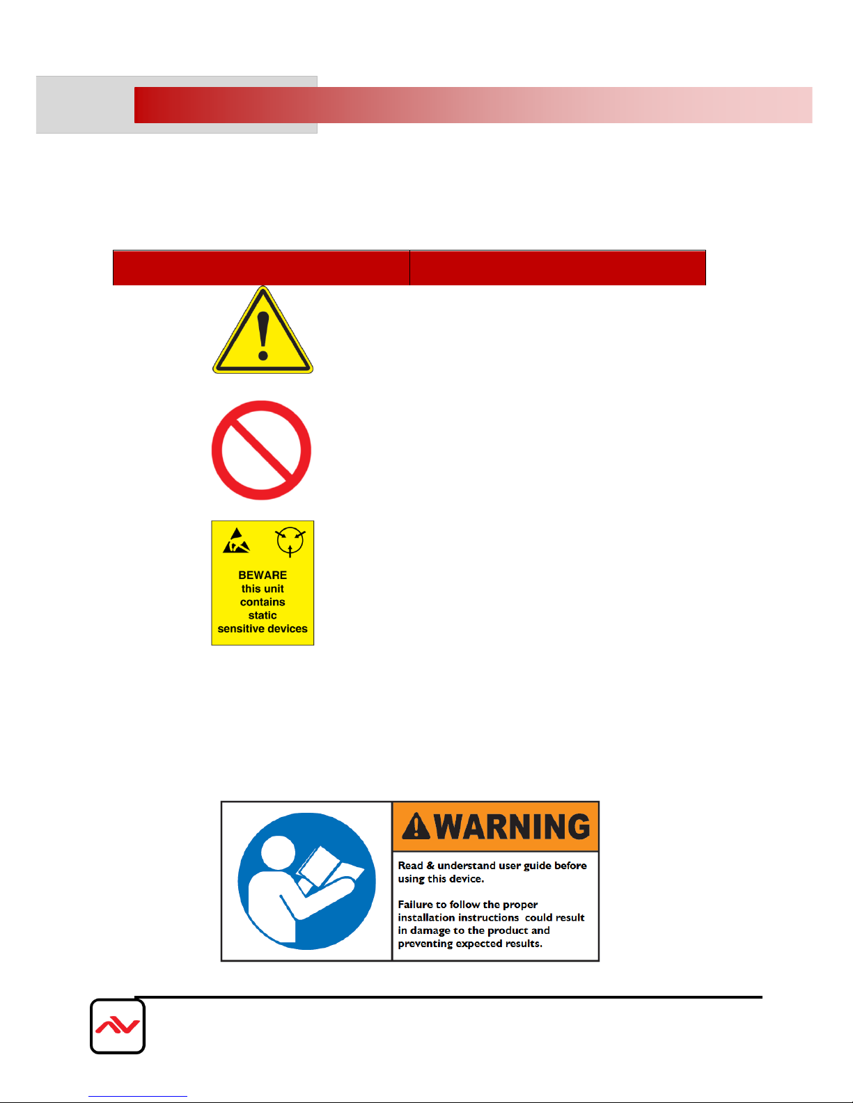
Warning symbols
Description
ONLY USE THE PROVIDED POWER CABLE
OR POWER ADAPTER SUPPLIED. DO NOT
TAMPER WITH THE ELECTRICAL PARTS.
THIS MAY RESULT IN ELECTRICAL SHOCK
OR BURN.
DO NOT TAMPER WITH THE UNIT. DOING
SO WILL VOID THE WARRANTY AND
CONTINUED USE OF THE PRODUCT.
THE VIDEO BOARDS ARE VERY SENSITIVE
TO STATIC. PLEASE ENSURE IF RACK
MOUNTED OR INSTALLED ON A SURFACE,
IT SHOULD BE IN A GROUNDED
ENVIROMENT.
Page 5

Page|5
www.avenview.com
2. INTRODUCTION
Avenview SC-HBT-HDMA-8X4 Presentation Scaler allows the user to switch and scale HDMI/
HDBaseT/PC/Composite Video signals from any one of its eight inputs and simultaneously display it on any of
its HMDI or HDBaseT outputs. The unit has and HDMI bypass output, allowing local monitoring of any of the
HDMI or HDBaseT inputs, and features full 5play™ convergence for easy integration of compatible
transmitters and receivers. Bonus feature to control via IR remote control, RS-232, IP/Telnet and WebGUI,
and the system status Front panel LCD
Features
- HDMI, HDCP and DVI compliant;
- Full 5Play™ convergence: Video, Audio, LAN serving, Bi-directional Power over Ethernet (PoE) AND Control (IR &
RS-232 bypass);
- Supports High-definition Audio: LPCM 7.1CH, Dolby TrueHD, Dolby Digital Plus and DTS-HD Master Audio
transmission (32-192kHz sample rate);
- Supports distances of up to 100 meters over industry standard CAT5e/6/7 cables;
- Supports scaling of any input signals to a wide range of HDTV and PC output resolutions up to 1080p and WUXGA (RB)
- Digital to Analog and Analog to Digital Audio conversion (DAC/ADC);
- Simultaneous video output of the selected source through the HDBaseT and HDMI outputs and audio output through the
digital coaxial and analog L/R outputs;
- Features four HDMI inputs with corresponding L/R audio inputs (3.5mm mini-jack), two HDBaseT CAT5e/6/7 inputs, PC
(15-pin D-sub) with L/R audio (3.5mm mini-jack) and Composite Video and L/R audio (3 RCA);
- Features two HDMI outputs, one HDBaseT CAT5e/6/7 output, one Digital Coaxial audio output and one L/R audio
3.5mm mini-jack output;
- Supports switchable HDMI bypass allowing local monitoring of any of the HDMI or HDBaseT inputs;
Supports Power over Ethernet (PoE) on the CAT5e/6/7 output to a compatible Receiver;
- Supports control via IR, Remote control, RS-232, Telnet, Web GUI and on-panel controls;
- Supports HDBaseT LAN serving function to compatible Receivers;
- Supports control via IR, Remote control, RS-232 and on-panel controls.
This model was tested with CAT6A (625MHz), 4-Pair, U/UTP-Unshielded cable, so if using Category cables of another
type, results may vary.
NOTE:
* The PoE function is designed for powering compatible Receiver units only.
* The non-PoE Receivers has to be powered with a power supply.
* Receivers (Rx) from different manufactures would not be compatible.
* Displaying HDMI 4Kx2K resolution would require the standard 4Kx2K HDMI cable and display for accurate results.
Page 6
Page|6
www.avenview.com
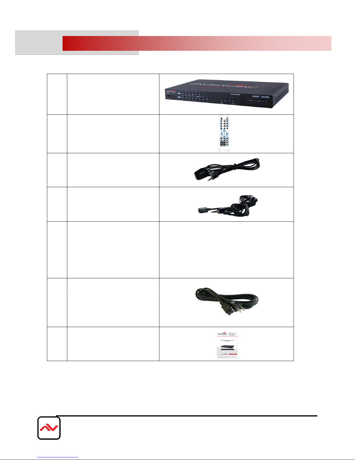
2.1 PACKAGE CONTENTS
Before you start the installation of the Extender, please check the package contents.
1
SC-HBT-HDMA-8X4
2
IR Remote (Batteries included)
3
IR Extender
4
IR Receiver
5
Power Adapter 24V/2.7A
7
User’s Manual
6
Power Cord
Page 7
Page|7
www.avenview.com
2.2 BEFORE INSTALLATION
Put the product in a level and stable location. If the product falls, it may cause damage or
malfunction to components within the casing.
Do not place the product in temperatures under 0˚C or over 50˚C. High humidity may also cause
the unit to malfunction.
Use the DC power adapter with correct specifications supplied with the unit. If the improper power
supply is used, this may result in malfunction of the unit and may cause fire.
Do not twist or pull by force the ends of the HDMI/UTP cable. It can cause malfunction.
2.2 CABLE SPECIFICATIONS
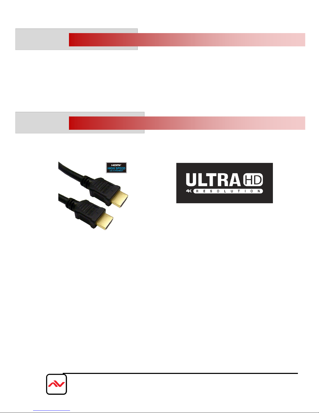
We highly recommend achieving best results with our SC-HBT-HDMA-8X4 you acquire a high quality 26
or 24 AWG HDMI cable with the below specifications to maintain signal integrity and distances.
Features
Length: 5m (16ft) to 15m (50ft)
Bandwidth: 10.2 Gbps data transfer rate
Supports Resolution: Up to 3840x2160 @ 24Hz and 4096x2160 @ 24Hz, 1080p @ 24Hz / 50/60Hz/3D
Conductor gauge: 26 / 24 AWG
Deep Color
3D Capable
CEC
Ethernet Channel
Audio Return Channel
Connector 1: HDMI (Type A) Male
Connector 2: HDMI (Type A) Male
Page 8
Page|8
www.avenview.com
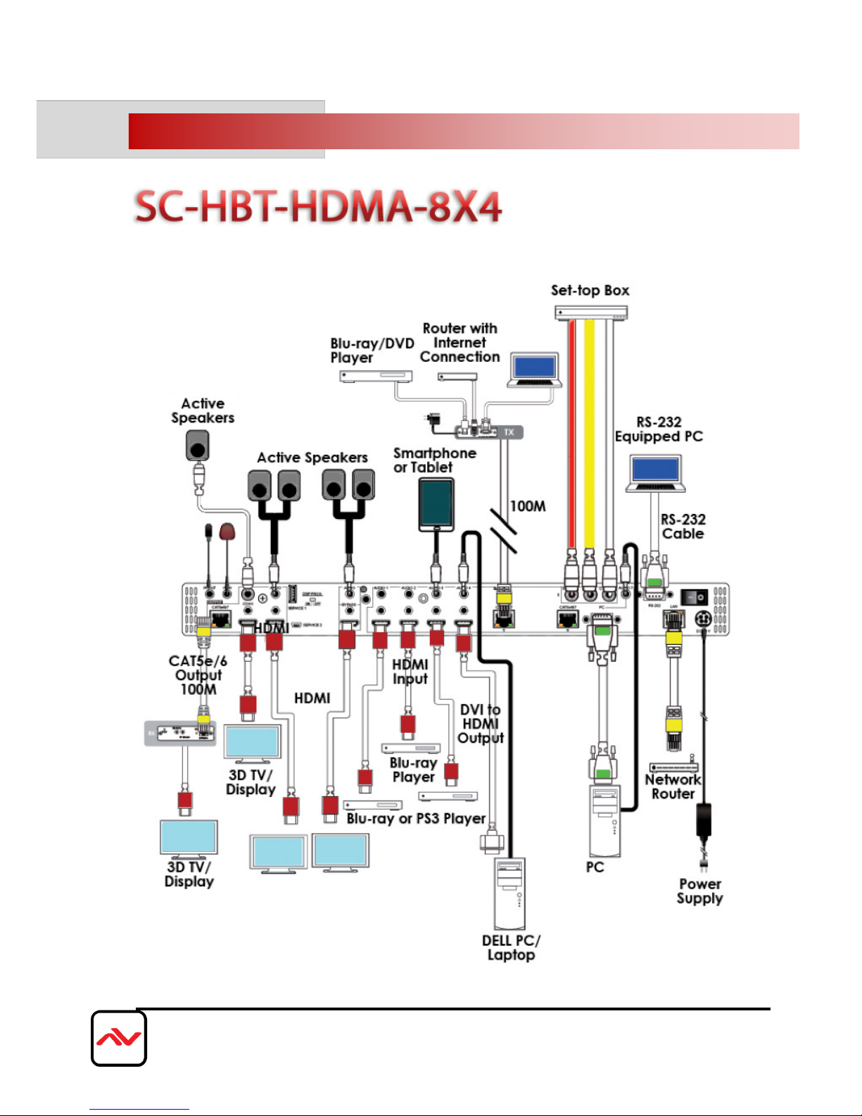
3. APPLICATION DIAGRAM
Page 9
Page|9
www.avenview.com
4. PANEL DESCRIPTION
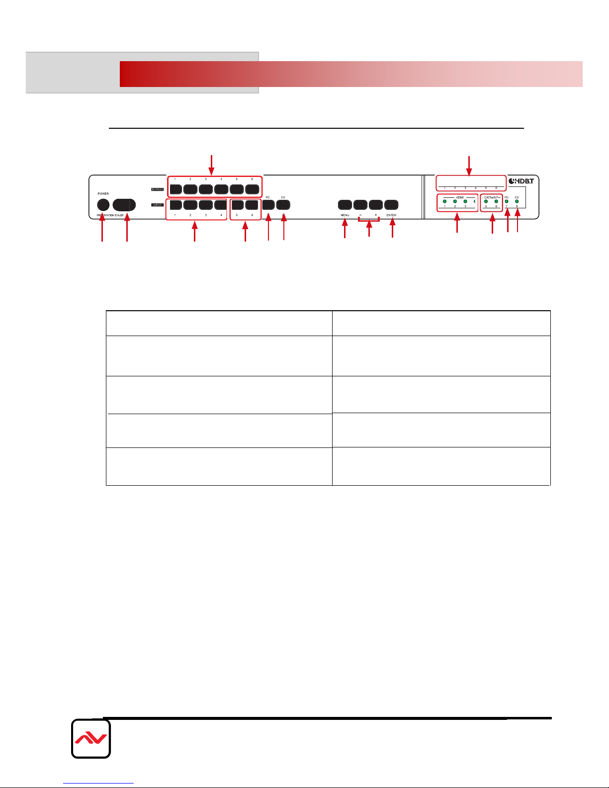
4.1 INPUT PANEL (SC-HBT-HDMA-8X4) Front Panel
1.
POWER: Turn ON the device and the LED will
illuminated.
2.
IR INTERFACE: Receives signal from the packaged
included remote control.
3.
INPUT HDMI 1-4 & LED: Select an input source
signal from the 4 HDMI input sources to be display.
LED illuminates accordingly.
4.
BYPASS & LED: Select an input source signal
from the 6 input sources to be display for BYPASS
output port. LED illuminates accordingly
5.
INPUT CAT5e/6/7 5-6 & LED: Select an input
source signal from the 2 CAT5e/6/7 input sources.
6.
INPUT PC & LED: Select PC input source signal
to be display on PC output port.
7.
INPUT CV & LED: Select CV input source signal s
to be display on CV output port.
3
5
3
5
4
4
1
2
6
7
8
9
10
6
7
8.
MENU: Press to enter into the menu and press
it again to confirm the selection.
9.
+/-: Press to move up/down under menu selection
or under volume control to adjust audio volume up/
down.
10.
ENTER: Press this button to confirm menu selection
Page 10
Page|10
www.avenview.com
IR IN
HDMI 1 DMI H 2
SERVICE 2
COAX
AUDIO
AUDIO AUDIO 7AUDIO 1 AUDIO 2 AUDIO 3 AUDIO 4
HDMI
BYPASS
CAT5e/6/7CAT5e/6/7 CAT5e/6/7 PC
HDMI 1 HDMI 2 3 DMI H 4 5 6 7
INPUT
R L CV
8
LAN
RS-232
DC 24 V
OUTPUT
IR OUT
SERVICE 1
ON OFF
DSP PROG.
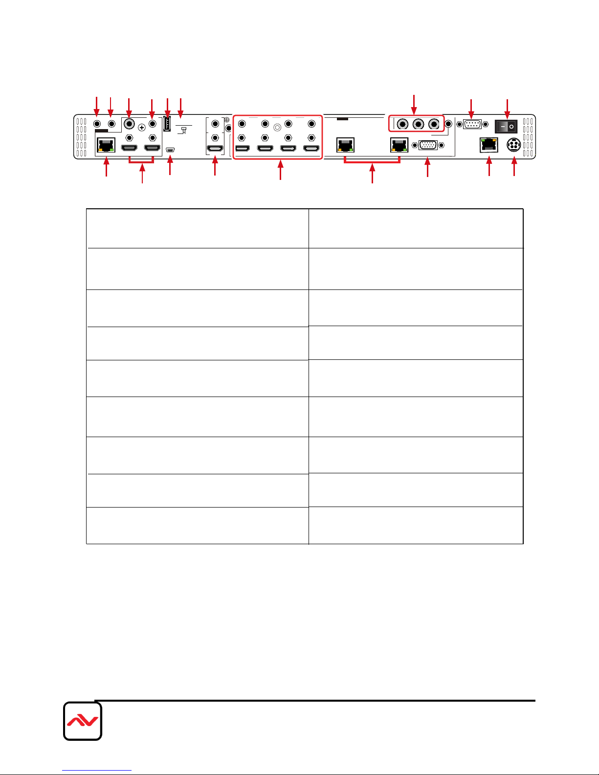
1.
IR OUT: Connect to the supplied IR Blaster cable for
IR signal transmission. Place the IR Blaster in direct lineof-sight of the device to be controlled.
2. IR IN: Connect to the supplied IR Extender cable
for IR signal reception. Remote should be in direct
line-of-sight of the IR Extender.
3.
OUTPUT CAT5e/6/7: Connect to the Receiver unit
with a Single CAT5e/6/7 cable for transmission of all
data signals.
4.
OUTPUT HDMI: Connect to a HDMI equipped
TV/monitor for display of the HDMI input source
signal.
5.
OUTPUT COAX: Connect to audio sound equipment
such as speaker or amplifier for audio sound output.
6.
OUTPUT AUDIO: Connect to peaker or
amplifier for audio sound output.
7.
SERVICE 1 & 2: Reserved for firmware update use
only.
4.2 INPUT PANEL (SC-HBT-HDMA-8X4) Rear Panel
4
10
11
13
1
2
5
6
IR OUT
7 8
14
16
12
15
17
7
9
3
9.
BYPASS: Connect to a HDMI equipped TV/monitor
with audio device for both video and audio output
display.
10.
INPUT HDMI 1-4 & AUDIO 1-4: Connect to
HDMI/DVI source
11.
INPUT CAT5e/6/7: Connect this port to CAT5e/6/7
Transmitter with CAT5e/6/7 cable to extend the
signal up to 100m.
12.
INPUT PC & AUDIO: Connect this port to PC/
Laptop with audio signal for input signal selecting.
13.
INPUT CV: Connect this port to source such as
video player or Set-Top-Box for input signal selecting.
14.
RS-232: Connect from PC/Laptop for RS-232
command sending to control the device.
15.
LAN: Connect from PC/Laptop with active internet
service for Web GUI control with RJ-45 terminated
cable.
16.
POWER TOGGLE: Powers the device On and
OFF
8.
DISPLAY PROG. SWITCH: Reserved for
firmware update use only. Default setting is on OFF.
17.
DC 24V: Connect the adaptor with power cord
included in the package and connect to AC wall
outlet for power supply.
Page 11
Page|11
www.avenview.com
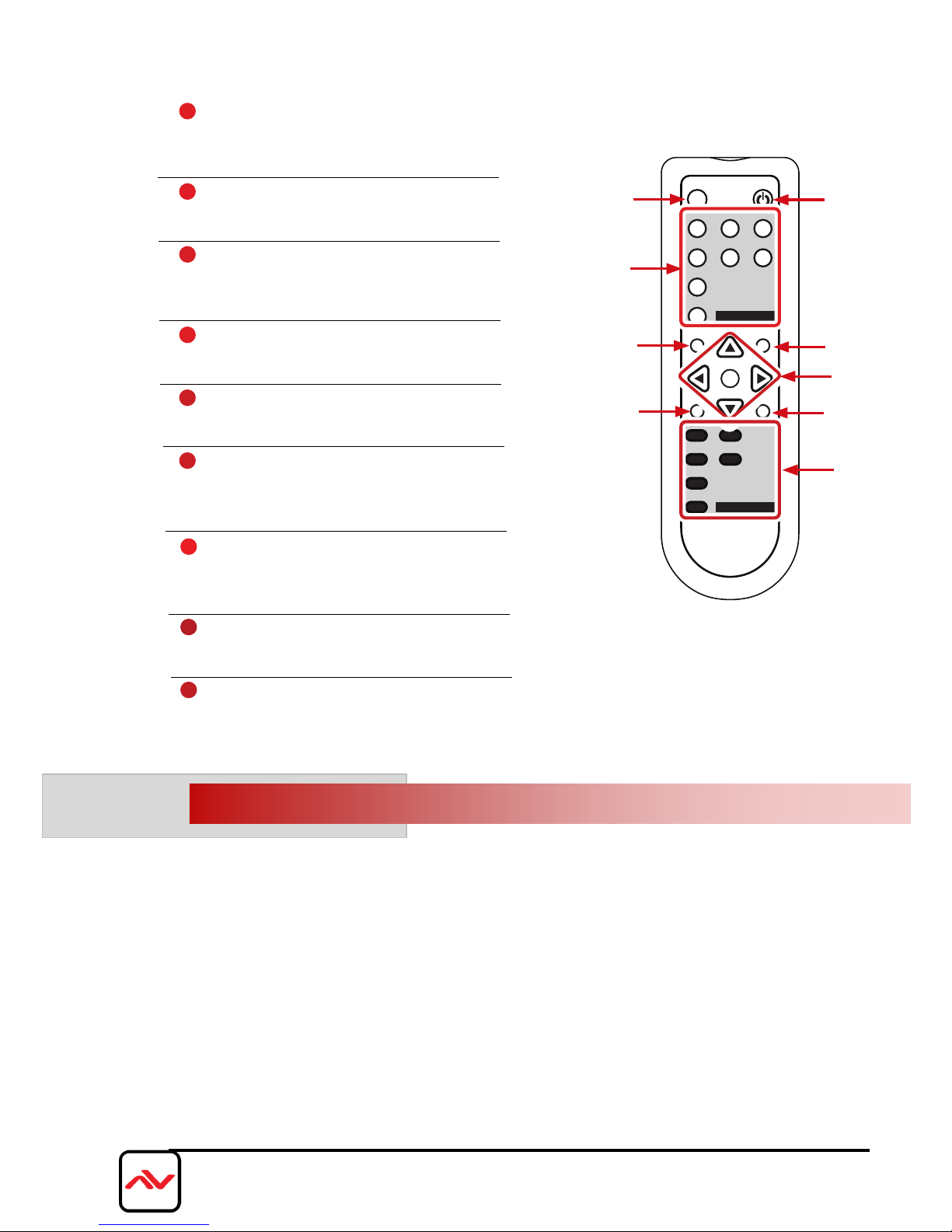
4.4
INSTALLATION (SC-HBT-HDMA-8X4)
To setup Avenview SC-HBT-HDMA-8X4 please follow these steps for connecting to a device:
1. Power off sources such as using Laptop/PC DVD player at Podium or where installed.
2. Connect up to 8 video Sources to the Multi INPUT- up to with Full HD, 3D and 4k x 2k support
3. Connect CAT 5/6 OUT to a compatible HBT-C6POEWP-R (Rx) CAT 5/6 IN and HDMI cable to HDMI or
VGA Displays
4. Plug in 24V/2.7DC power adapter to the screw terminal HBT-C6POEWP-S- Green LED illuminate
5. Power on all 8 Sources and HDMI Display
7. When the Input is connected and turned on the corresponding LED will light on the LINK LED when signal
is detected and transmitting.
MUTE
CAT5e/6/7
POWER
EXIT
MENU
RESET
ADJUST
-
+
OK
HDMI 1
CAT5e/6/7 1
HDMI 2
HDMI 3
CAT5e/6/7 2
HDMI 4
HDMI 4
HDMI 1
1
PC
HDMI 2
VC2
HDMI 3
INPUT
BYPASS
1
POWER:
Press this button to switch the device
ON or to put the device into Standby
mode.
2
MUTE:
Press this button to mute output audio
sound.
3
INPUT:
Press these buttons one time each
to select input source for outputs
display.
4
MENU:
Press this button to enter into the OnScreen Menu.
5
EXIT:
Press this button to exit menu
selection.
6
▲▼◄►& OK:
Press OK to conrm the selection
or use the directional buttons to
navigate the On-Screen-Menu.
7
ADJUST:
Press this button when output image is not tting the display's
screen perfectly. The device will auto adjust the image to full
screen.
8
RESET:
Press this button to set the deivice back into the fatory default
setting.
9
BYPASS:
Press these buttons to select an input source for Bypass output port
to display.
2
3
5
8
1
4
7
6
9
4.3 REMOTE CONTROL
Page 12
Page|12
www.avenview.com
4.5
IR CABLE DEFINITION
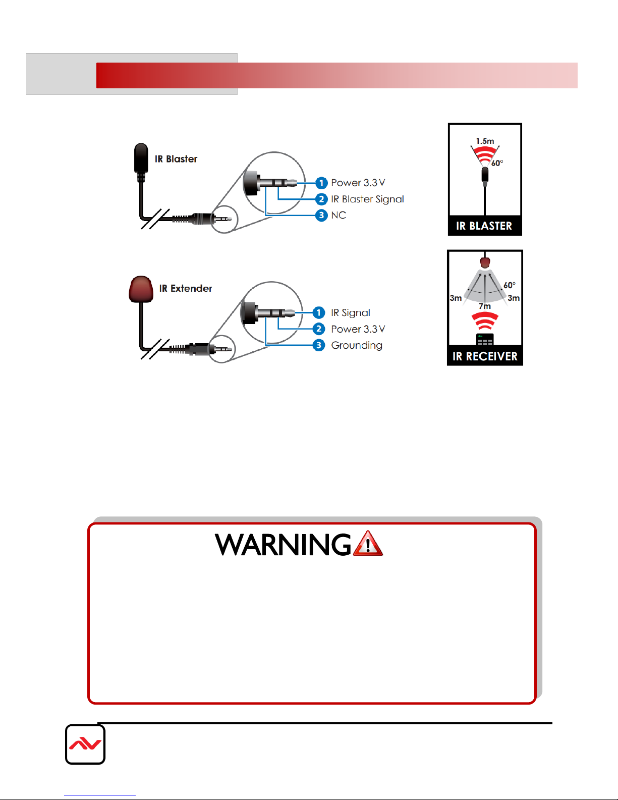
IR Sockets
IR BLASTER: plug in the IR blaster to the HBT-C6POE-R to emit all IR command signals received from the IR
Extender plugged into the Rx (Monitor Side) to control the devices corresponding to the IR signals.
Example: Set Top Box or DVD player (The Source).
IR EXTENDER: plug in the IR Extender into the (RX) Receiver (Monitor Side) to receive all IR command signals
from the IR remote controls of the corresponding source.
Example: Set Top Box or DVD player (IR Remote Control).
NOTE: Incorrect placement of IR Blaster and IR Extender into the extender may result in
the failure of the IR extenders.
Please check carefully before plugging in the IR extender to the respective IR sockets.
It is clearly marked and IR IN: IR EXTENDER /IR OUT: IR BLASTER
WARRANTY WILL NOT COVER THE DAMAGE.
Page 13
Page|13
www.avenview.com
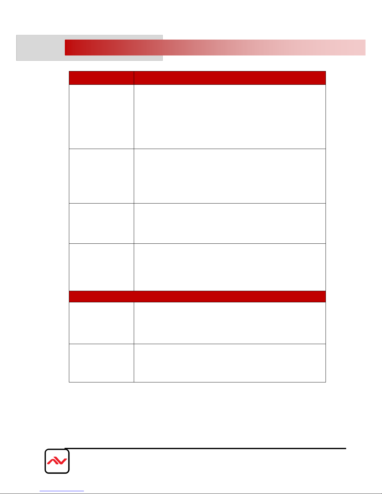
5. GENERAL TROUBLESHOOTING
PROBLEM
POSSIBLE SOLUTION
NO IMAGE
Check if connection to the source and the display are correct.
Ensure that display device supports 480p, 720p and 1080p 4K@30
resolution
Terminated to 568B standard with Shielded Ends Recommended
High Quality CAT5/6/7 Cable helps signal transmission
Please use the supplied power supply-DC 24V 2.7A
Check LED Link light see (Section 3 Panel Description)
Check LED Sync light see (Section 3 Panel Description)
EDID ISSUE
EDID MODE-: The unit will detect the 1st CAT5e/6/7 output’s
EDID. When obtained a (4K2K) Ultra HD 3840x2160 EDID the
signal is transmitted.
If the 1st CAT5e/6/7 output is without a Ultra HD 3840x2160
EDID the unit will detect all output's EDID and Transmit the signal
that all outputs can accept.
Set-Top Box
No Picture
HDBaseT and HDMI 1.3 standards support CLOCK
STRETCHING for i2c buss protocol
Example set top boxes like Scientific Atlantic results no picture.
This can be resolved by swapping out the box for a newer version
that supports HDMI 1.3 not HDMI 1.2
NO Infrared
Communication
Ensure the UTP cable is run within the wall away from EMI and
High Voltage power Lines.
Please check manual of device to ensure proper placement of IR
Blaster on IR EYE.
Some LED /Plasma TV have EMI interference with the IR
Extender, please place the IR Rx 3-6” away from Screen
Recommended TEST
End-to-End Testing
HDBaseT system, a final end-to-end test of all the A/V components
should take place. These tests include checking the HDMI stream at
the far end (sink end), the clock rate, frame compare, video pattern,
audio, EDID and HDCP with Quantum 780 (recommended)
Passive Monitoring:
Passive monitoring enables an integrator to view the HDCP
transactions, EDID exchange, as well as the connection events
between the actual devices in the network.
NOTE
Addional info on Guidelines to Test & Troubleshoot HDBaseT Systems
Can be retreived from our website under the category Downloads for this
product SC-HBT-HDMA-8X4
Page 14
Page|14
www.avenview.com
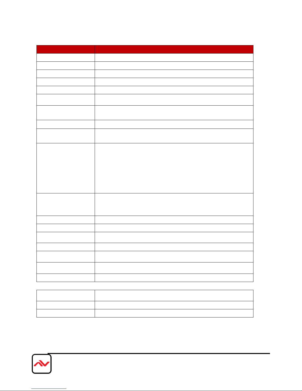
SECTION 6: SPECIFICATIONS
ITEM
DESCRIPTION
UNITS
SC-HBT-HDMA
-8X4
UNIT DESCRIPTION
8x4 HDBaseT Presentation Switcher
HDMI COMPLIANCE
YES HDBaseT
HDCP
Yes
VIDEO BANDWIDTH
[10.2Gbps]
SUPPORTED
RESOLUTIONS
480i-1080p@50/60,1080p@24 VGA-WUXGA(RB)
CAT5/6/7 CABLE
4K2K: (3840X2160@30Hz) ~ 75meter (250feet) (CAT6e) / 100meter (330feet) (CAT6a)
FULL HD: (1080p) ~ 100meter (330feet) (CAT6e) /110meter (360feet) (CAT6a)
AUDIO SUPPORT
LPCM 2CH, Dolby Digital 2~5.1CH/ DTS
ESD PROTECTION
Human body model — ±8kV (air-gap discharge)
& ±4kV (contact discharge)
INPUT
4 x HDMI
4 x L/R
2 x CAT5e/6/7
1 x PC + L/R
1 x CV+L/R
2 x USB (Service only)
1 x LAN
1 x RS-232
1 x IR
OUTPUT
1 x L/R1 x Coaxial
1 x CAT5e/6/7
1 x HDMI Bypass
2 x HDMI
HDMI CONNECTOR
Type A (19 pin female)
LED
GREEN/YELLOW LED
IR FREQUENCY
30~50kHz
DIMENSIONS (L X W X H)
438mm (W) x 275mm (D) x 44mm (H)
WEIGHT
7.5 lbs
3410g
POWER SUPPLY
24V / 2.7A DC
(US/EU standards, CE/FCC/UL certified)
POWER CONSUMPTION
85 Watt
ENVIRONMENTAL
OPERATING
TEMPERATURE
32˚ ~ 104˚F (0˚ to 40˚C)
STORAGE TEMPERATURE
-4˚ ~ 140˚F (-20˚ ~ 60˚C)
RELATIVE HUMIDITY
20~90% RH (non-condensing)
Page 15

Page|15
www.avenview.com
NOTICE
1.
All HDMI over UTP transmission distances are measured using Belden CAT6A (625MHz), 4-Pair,
U/UTP-Unshielded, Riser-CMR, Premise Horizontal Cable, 23 AWG Solid Bare Copper
Conductors, Polyolefin Insulation, Patented Double-H spline, Ripcord, PVC Jacket using Quantum
980 signal HDMI Video Generator Module Video Pattern Testing.
2. The transmission length is largely affected by the type of category cables, also the type of HDMI
sources, and the type of HDMI display. The testing result shows solid UTP cables (usually in the
form of 300m or 1000ft bulk cable) can transmit a lot longer signals than stranded UTP cables
(usually in the form of patch cords). Shielded STP connectors are better suit than unshielded UTP
connectors. A solid UTP CAT5e cable shows longer transmission length than stranded STP CAT6
cable. For long extension users, solid cables are your only choice.
3. EIA/TIA-568-B termination (T568B) for category cables is recommended for better performance.
4. To reduce the interference among the unshielded twisted pairs of wires in category cable, you can
use shielded STP cables with shielded connector to improve EMI problems, which occurs in long
transmission.
5. Because the quality of the category cables has the major effects in how long transmission distance
will be made and how good is the received display, the actual transmission length is subject to your
category cables. For resolution greater than 1080i or 1280x1024, a solid CAT6 cable is the only
viable choice.
Page 16
TECHNICAL SUPPORT
Disclaimer
While every precaution has been taken in the preparation of this document, Avenview Inc. assumes no liability with respect to the operation or use of
Avenview hardware, software or other products and documentation described herein, for any act or omission of Avenview concerning such products or this
documentation, for any interruption of service, loss or interruption of business, loss of anticipatory profits, or for punitive, incidental or consequential damages
in connection with the furnishing, performance, or use of the Avenview hardware, software, or other products and documentation provided herein.
Avenview Inc. reserves the right to make changes without further notice to a product or system described herein to improve reliability, function or design.
With respect to Avenview products which this document relates, Avenview disclaims all express or implied warranties regarding such products, including but
not limited to, the implied warranties of merchantability, fitness for a particular purpose, and non-infringement.
Control Your Video
USA Head Office
Office Avenview Corp.
275 Woodward Avenue
Kenmore, NY14217
Phone: +1.716.218.4100
Fax: +1.866.387-8764
Email: [email protected]
Canada Sales
Avenview
151 Esna Park Drive, Units 11 & 12
Markham, Ontario, L3R3B1
Phone: 1.905.907.0525
Fax: 1.866.387.8764
Email: [email protected]
Avenview Europe
Avenview Europe
Demkaweg 11
3555 HW Utrecht
Netherlands
Phone: +31(0)85 2100 613
Email: [email protected]
Avenview Hong Kong
Unit 8, 6/f., Kwai Cheong Centre,
50 Kwai Cheong Road,
Kwai Chung, N.T.
Hong kong
Phone: 852.3575.9585
Email: [email protected]
 Loading...