

Page 1

www.avenview.com
1
KVM-C5 Series
User’s Guide
© 2007 Avenview™ Inc. All rights reserved.
The contents of this document are provided in connection with Avenview Inc. (“Avenview”) products. Avenview makes no representations
or warranties with respect to the accuracy or completeness of the contents of this publication and reserves the right to make changes to
specifications and product descriptions at any time without notice. No license, whether express, implied, or otherwise, to any intellectual
property rights is granted by this publication. Except as set forth in Avenview Standard Terms and Conditions of Sale, Avenview assumes
no liability whatsoever, and disclaims any express or implied warranty, relating to its products including, but not limited to, the implied
warranty of merchantability, fitness for a particular purpose, or infringement of any intellectual property right.
Reproduction of this manual, or parts thereof, in any form, without the express written permission of Avenview Inc. is strictly
prohibited.
Disclaimer
While every precaution has been taken in the preparation of this document, Avenview Inc. assumes no liability with respect to the
operation or use of Avenview hardware, software or other products and documentation described herein, for any act or omission of
Avenview concerning such products or this documentation, for any interruption of service, loss or interruption of business, loss of
anticipatory profits, or for punitive, incidental or consequential damages in connection with the furnishing, performance, or use of the
Avenview hardware, software, or other products and documentation provided herein.
Avenview Inc. reserves the right to make changes without further notice to a product or system described herein to improve reliability,
function or design. With respect to Avenview products which this document relates, Avenview disclaims all express or implied warranties
regarding such products, including but not limited to, the implied warranties of merchantability, fitness for a particular purpose, and
non-infringement.
Page 2

www.avenview.com
2
Table of Contents
Getting Started ....................................................................................................................................... 3
Key Features ........................................................................................................................................... 3
Panel Description ................................................................................................................................... 4
Transmitter KVM-C5-S and Receiver KVM-C5-R ................................................................................ 4
Installation and Operation ..................................................................................................................... 5
VGA-C5-S Transmitter Installation ..................................................................................................... 5
KVM-C5-R Receiver Installation ......................................................................................................... 6
Specifications ......................................................................................................................................... 9
Page 3

www.avenview.com
3
Getting Started
The Smart KVM Extender can extend the KVM control (Keyboard / Video / Mouse) up to 300m (1000
ft) over a single Cat5e cable. Built-in matured KVM technology and video signal processing can
extend KVM signal correctly and provide a premium video resolution of up to 2048x1536@300m
(1000 ft).
KVM-C5 is perfect for centralized computer management. By adapting KVM switch or KVM Drawer,
you can control multiple computers on a rack locally or in a remote location. This unit is also suitable
for office to secure all PCs in a computer room and extend KVM console to every desktop to ease
the maintenance, save desktop space and prevent PC to be accessed through USB or other network.
Built-in smart keyboard and mouse simulation, it can support advanced function of Logitech or
Microsoft mouse and work on any PS/2 PC or by using a USB to PS/2 converter to extend a USB
interface computer (Ex: SUN / Mac).
The KVM Extender is designed not only to provide accurate KVM signal, but also easy to install. It
provides a magnetic pad and a attachable metal plate, so you can place the KVM Extender very
easily on the surface of PC or any preferred place like wood or concrete.
Key Features
Extend the Keyboard / Video / Mouse of PC or KVM Switch by Cat 5 / 5e / 6 cable
Supported VGA Resolution and Distance: up to 2048x1536 @ 300m (1000 ft
Supports VGA, SVGA, XGA, TFT-LCD with DDC2B
Supports PS/2 type PC or KVM Switch application
Plug & Play
Supports MS-DOS, Windows, FreeBSD, Linux, Unix, Novell
Auto KVM model detection for optimum setup
Supports advanced function of Logitech and Microsoft Mice
Manual signal control (Gain & Focus) for different extended distance and achieving the best quality
Integrated 3-in-1 KVM cable for PC or KVM Switch connection
Transmitter and Receiver build with FOUR color LEDs to indicate system status
Equipped with magnetic pad and metal plate for easy installation
Page 4
www.avenview.com
4
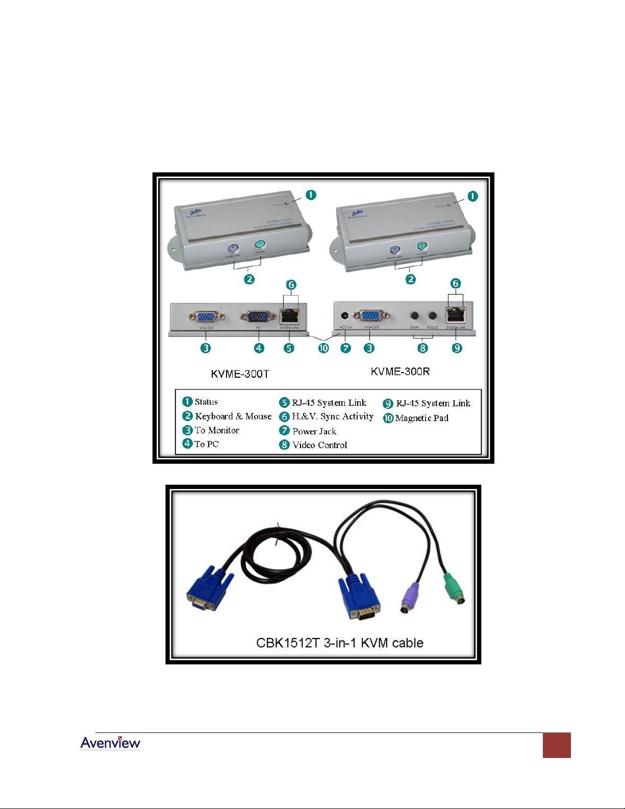
Panel Description
Transmitter KVM-C5-S and Receiver KVM-C5-R
Page 5
www.avenview.com
5
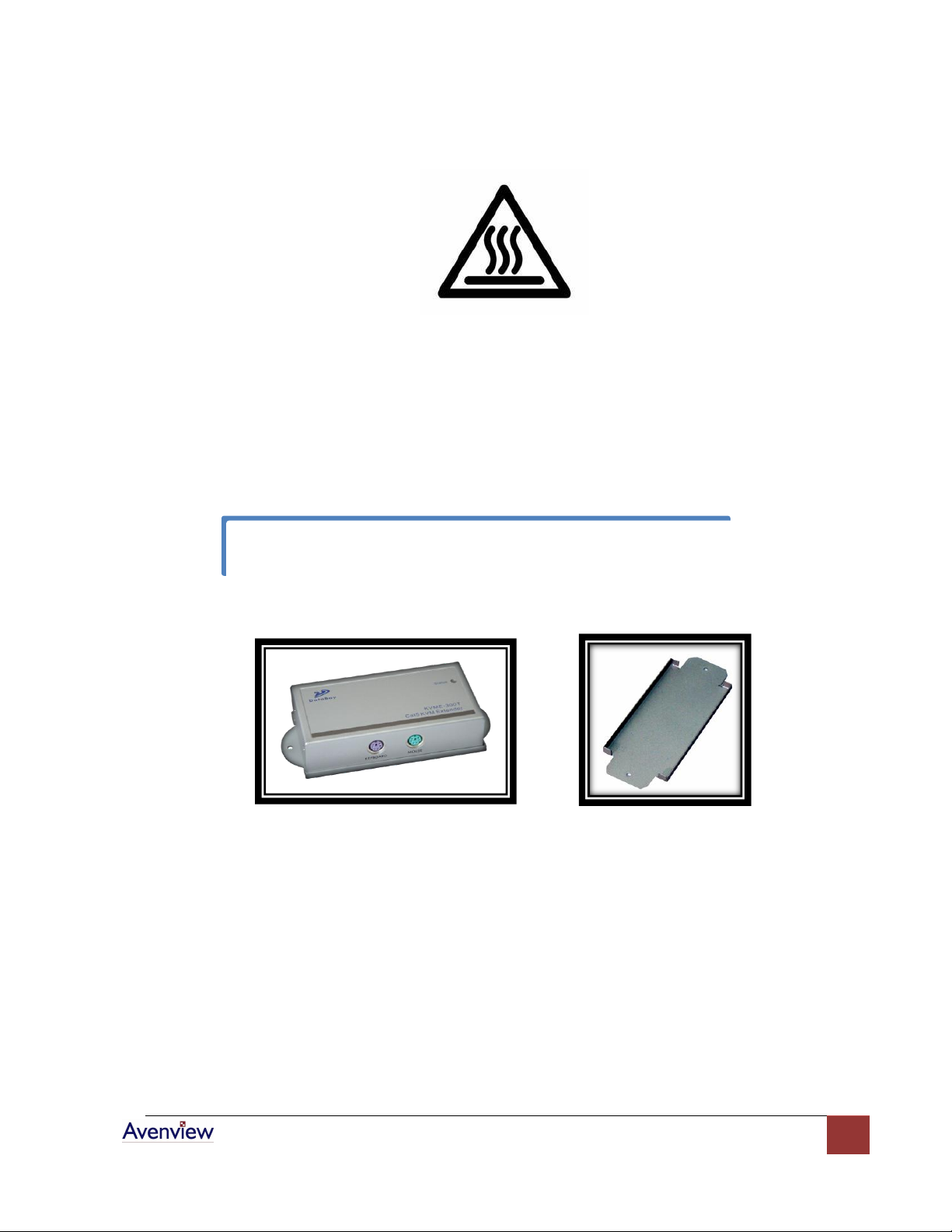
You can use magnetic pad to attach the unit on a metal plane or use attachable Rack
Mounting Kit to fix the unit on selected area by screw.
Installation and Operation
VGA-C5-S Transmitter Installation
a. Site Selection: In your first time installation, place Transmitter (VGA-C5-S) near the PC or
KVM Switch console you want to extend.
Unit attached with Rack Mounting Kit
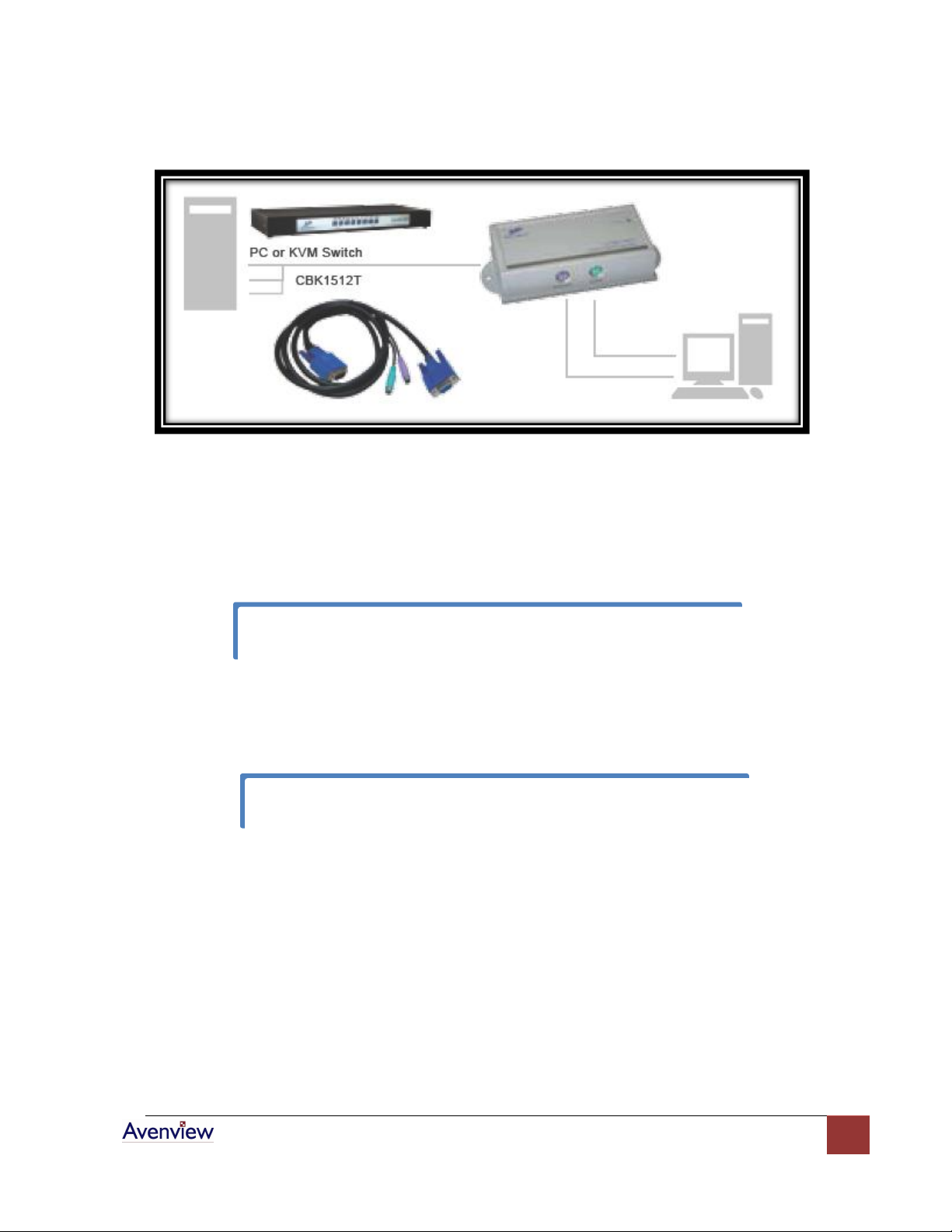
b. Device Connection: Connect Keyboard / Video / Mouse to Transmitter. Use 15 Pin
Integrated 3-in-1 KVM Cable, and connect the 15 Pin end to the Transmitter and other end
of the cable to corresponding Keyboard / Video / Mouse port of PC or KVM Switch.
Page 6
www.avenview.com
6
Installation Diagram of KVM-C5-S Transmitter
Test the functionality of the monitor and ensure that Keyboard and Mouse are working
properly to finish the installation of the Transmitter.
You can use magnetic pad to attach the unit on a metal plane or use attachable Rack
c. Function Test: Power ON your PC, the Transmitter will take the power from the PC’s PS/2
connection. The front “PC ON” LED of the Transmitter will keep blinking Green to indicate
the unconnected status of System Link. The LEDs above RJ45 will turn ON to indicate the
activation of Video Signal.
-
KVM-C5-R Receiver Installation
a. Site Selection: Place KVM-C5-R Receiver in an appropriate place.
Cable Selection: For best VGA signal, use Cat 5e or Cat 6 cable.
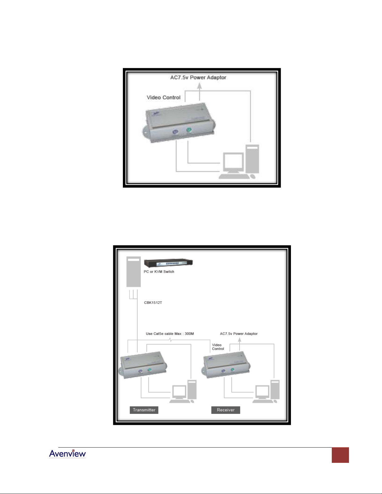
b. Power ON: Plug power adapter to the Receiver and connect Keyboard / Video / Mouse to
Receiver. The LEDs of unit should keep blinking to indicate the unconnected status of the
cable.
Page 7
www.avenview.com
7
Installation Diagram of KVM-C5-R Receiver
c. Connect Cable: Plug two ends of Cat 5 / 5e / 6 cable to Transmitter and Receiver’s RJ45
“SYSTEM LINK” ports. Now the LEDs above RJ45 should turn on to indicate the activation of
Video Signal and correct connection of the cable.
Connection Diagram of KVM Extender
Page 8
www.avenview.com
8
d. Function Test: After installation, you will be able to control Keyboard / Video / Mouse from
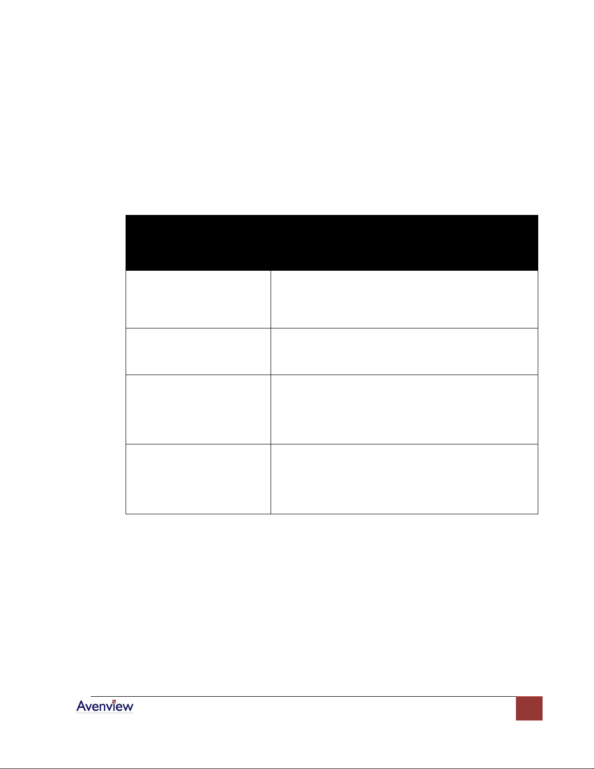
General Troubleshooting
Problem
Possible Solution
Screen Defects Appear
Check that VGA resolution and frequency is not over the
limit of monitor display.
Check your current resolution, refresh rate and color depth
settings in the Settings and Monitor tabs in your Display
Properties dialog.
Off-Center Screen Image, Odd
Colors or No Picture
Try adjusting the brightness, sharpness, contrast, and color
balance controls of your monitor.
Try adjusting the centering and positioning controls of your
monitor to position the picture on the screen.
No Image
Ensure that the monitor cable is securely fastened to the
VGA and Monitor port.
Try to connect monitor directly to a PC to ensure basic
functionality of these devices.
Check if the Receiver’s power adapter is AC 7.5V with a
capacity of over 1Amp.
Keyboard or Mouse Problem
Ensure that Keyboard and Mouse cables are connected at
appropriate ports.
Restart the PC to ensure it is properly detected.
Connected Keyboard / Video / Mouse directly from
Transmitter to your PC or KVM Switch to verify basic
function.
the Receiver. During the operation of Receiver, the STATUS LED of the Transmitter will turn
on Red to indicate the operation of the Receiver.
e. Manual VGA Adjustment: The video quality can be manually adjusted by the Control of
GAIN and FOCUS at the back of the Receiver unit.
Page 9
www.avenview.com
9
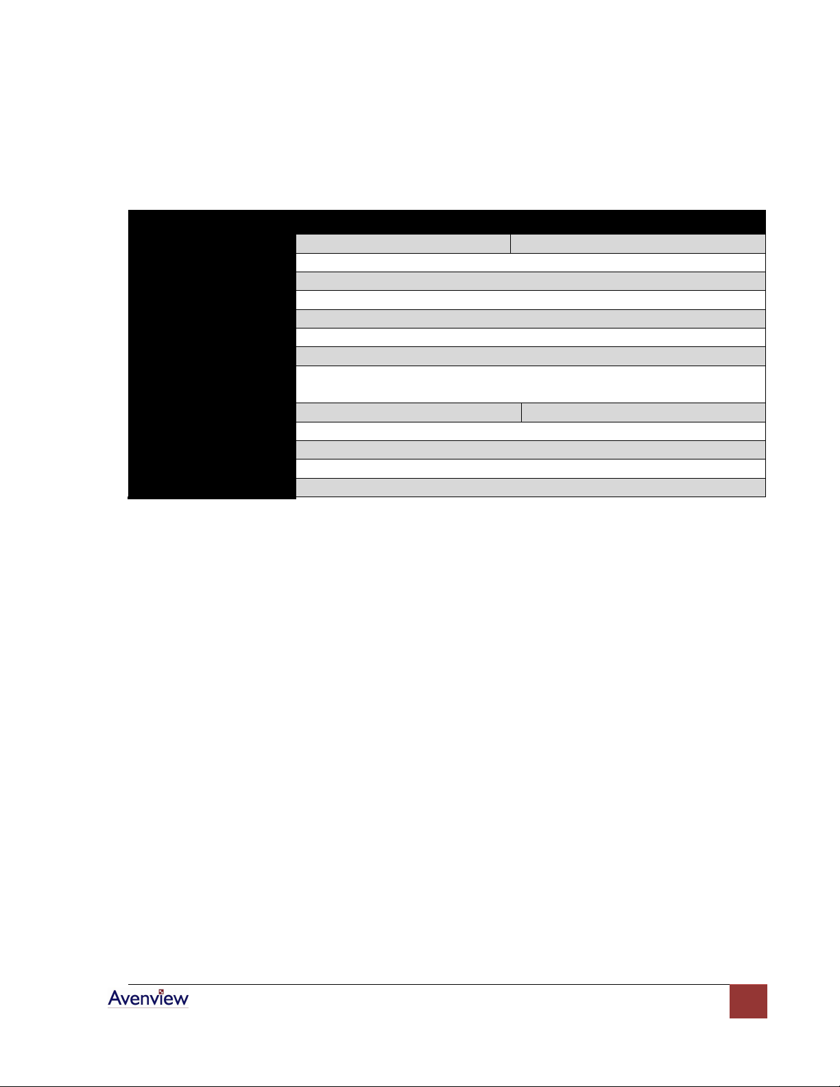
Specifications
Model
KVM-C5-S
KVM-C5-R
Description
Transmitter
Receiver
Keyboard
PS/2 Female
Mouse
PS/2 Female
Video
D-Sub 15 Female
To PC / KVM Switch
Integrated D-Sub 15 pin KVM Cable
System Link
RJ45
LED Display
Status, H. Sync, V. Sync
Max Resolution &
Distance
2048x1536@300m (1000 ft)
Power Consumption
PS/2 AC 7.5V, 250mA
AC 7.5V, 250mA
Dimension (LxWxH)
62 x 113 x 29 mm
Operating Temperature
0 - 50°C
Storage Temperature
-20 ~ 60°C
Humidity
10 ~ 90%
Page 10

www.avenview.com
10
 Loading...