

Page 1
VIDEO WALLS VIDEO PROCESSORS
VIDEO MATRIX SWITCHES
EXTENDERS SPLITTERS WIRELESS
Control Your Video
CABLES & ACCESSORIES
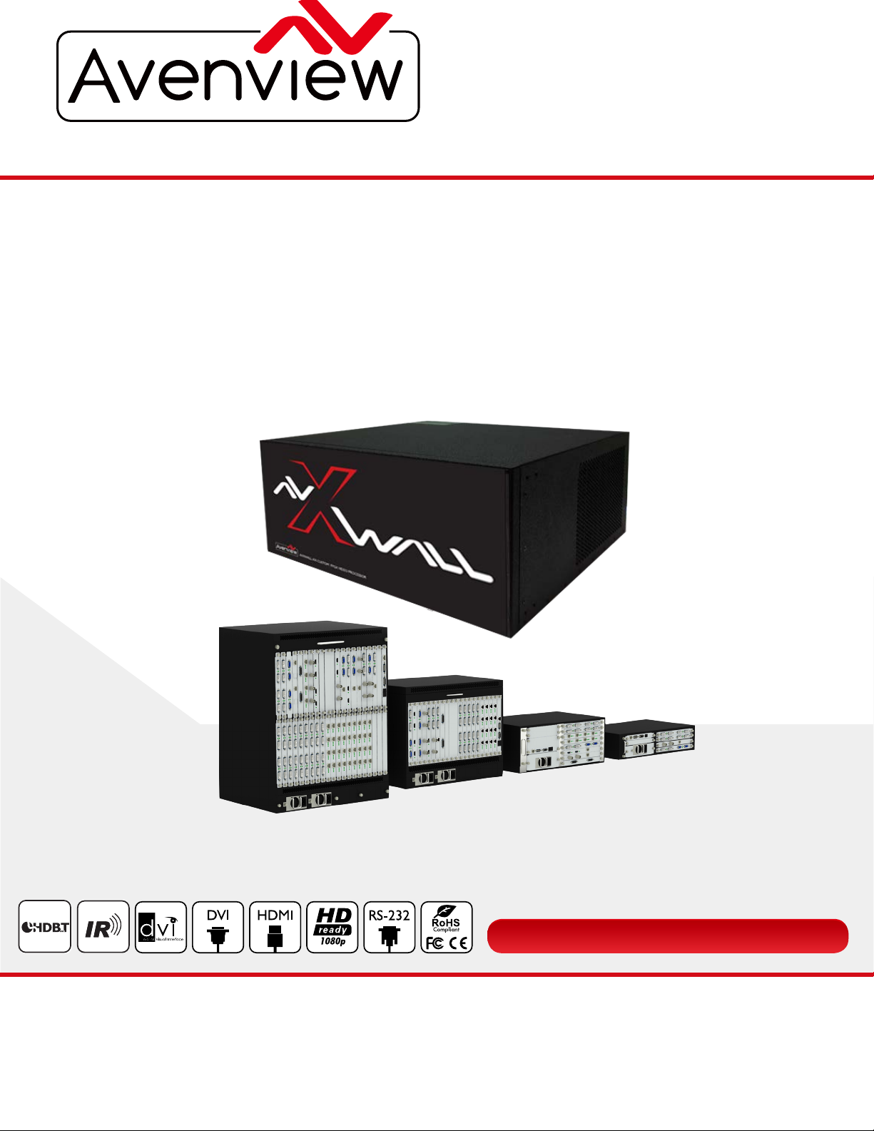
4K Modular Video Wall Processor
Model #: HDM-AVXWALL
© 2016 Avenview Inc. All rights reserved.
The contents of this document are provided in connection with Avenview Inc. (“Avenview”) products. Avenview makes no representations or
warranties with respect to the accuracy or completeness of the contents of this publication and reserves the right to make changes to specifications
and product descriptions at any time without notice. No license, whether express, implied, or otherwise, to any intellectual property rights is granted
by this publication. Except as set forth in Avenview Standard Terms and Conditions of Sale, Avenview assumes no liability whatsoever, and disclaims
any express or implied warranty, relating to its products of Avenview Inc. is strictly prohibited.
Page 2
Product Application & Market Sectors
Corporate House Of Worship
Military Residential
Education Industrial
Medical Aviation
www.avenview.com
Page 3

www.avenview.com
Page
TABLE OF CONTENTS
1. GETTING STARTED ...........................................................................................................................1
1.1 IMPORTANT SAFE GUARDS ..............................................................................................................1
1.2 SAFETY INSTRUCTIONS ...................................................................................................................1
1.3 REGULATORY NOTICES FEDERAL COMMUNICATIONS COMMISSION ....................................2
2. INTRODUCTION AND FEATURES ...................................................................................................3
2.1 PACKAGE CONT
2.2 BEFORE INSTALLATION
2.3 PANEL DESCRITION.... ......................................................................................................................5
2.3.1 HDM-AVXWALL Front panel .....................................................................................................5
2.3.2 HDM-AVXWALL Rear panel ......................................................................................................5
3. INSTALLATION ...................................................................................................................................6
4. APPLICATION DIAGRAM...................................................................................................................7
5. SOFTWARE ........................................................................................................................................8
5.1 OPERATION AND CONFIGURATION ........................................................................................8
A. CONNECT ..........................................................................................................................9
- CONFIGURATION ...........................................................................................................11
- TEST SIGNAL ...................................................................................................................12
- INPUT MANAGEMENT ..................................................................................................13
- ADVANCED SETTINGS ..................................................................................................13
B. DASHBOARD.....................................................................................................................14
- PRESETS ..........................................................................................................................14
- LOCK ..............................................................................................................................15
- LAYER MODE .................................................................................................................15
- BRING T FRONT ...........................................................................................................15
- CLOSE ALL .....................................................................................................................16
- DELETE ..........................................................................................................................16
ENTS ......................................................................................................................4
....................................................................................................................5
C. VIEW ..................................................................................................................................17
- PREVIEW ........................................................................................................................17
- CARDS ...........................................................................................................................18
- SLIDESHOW ..................................................................................................................18
- REFRESH ........................................................................................................................19
3
Page 4

D. EDIT............................................................................................................................................19
- GROUP .....................................................................................................................................19
- PRESET LIST ............................................................................................................................19
- BACKGROUND ......................................................................................................................19
E. OPERATION...............................................................................................................................19
F. TOOLS........................................................................................................................................20
- EDID.........................................................................................................................................20
- FIND CAMERA ........................................................................................................................20
- IMPORT AND EXPORT .........................................................................................................20
G. SETTINGS...................................................................................................................................20
- LICENSE...................................................................................................................................
- USERS .......................................................................................................................................2
- FIRMWARE ..............................................................................................................................2
- WINDOW FONT.....................................................................................................................20
- LANGUAGE.............................................................................................................................20
- VERSION .................................................................................................................................20
- ABOUT ....................................................................................................................................20
6.
SPECIFICATIONS ...............................................................................................................................21
20
0
0
7. INPUT / OUTPUT CARDS ................................................................................................................22
7.1 INPUT CARDS .........................................................................................................................22
7.2 OUTPUT CARDS......................................................................................................................24
8. MODELS AND SCALES ................................................................
9. GENERAL TROUBLESHOOTING ...............................................................................................
NOTICE ..............................................................................................................................................29
NOTES ........ ......................................................................................................................................30
.....................................................26
.....27
www.avenview.com
Page 3
Page 5
www.avenview.com
Page
1. GETTING STARTED
SECTION 1: GETTING STARTED
1.1 IMPORT
Please read all of these instructions carefully before you use the device. Save this manual for future reference.
What the warranty does not cover
• Any product, on which the serial number has been defaced, modified or removed.
• Damage, deterioration or malfunction resulting from:
• Accident, misuse, neglect, fire, water, lightning, or other acts of nature, unauthorized product modification, or failure to
follow instructions supplied with the product.
• Repair or attempted repair by anyone not authorized by us.
• Any damage of the product due to shipment.
• Removal or installation of the product.
• Causes external to the product, such as electric power fluctuation or failure.
• u se of supplies or parts not meeting our specifications.
• Normal wear and tear.
• Any other causes which does not relate to a product defect.
• Removal, installation, and set-up service charges.
ANT
SAFEGUARDS
1.2 SAFETY INSTRUCTIONS
The Avenview HDM-AVXWALL Modular Video Wall processor has been tested for conformity to safety regulations and
requirements, and has been certified for international use. However, like all electronic equipment’s, the HDM-AVXWALL
should be used with care. Read the following safety instructions to protect yourself from possible injury and to minimize the
risk of damage to the unit.
Do not dismantle the housing or modify the module.
!
Dismantling the housing or modifying the module may result in electrical shock or burn.
!
Refer all servicing to qualified service personnel.
!
Do not attempt to service this product yourself as opening or removing housing may expose you to dangerous voltage
!
or other hazards
keep the module away from liquids.
!
Spillage into the housing may result in fire, electrical shock, or equipment damage. If an object or liquid falls or spills on
!
to the housing, unplug the module immediately.
Have the module checked by a qualified service engineer before using it again.
!
Do not use liquid or aerosol cleaners to clean this unit. Always unplug the power to the device before cleaning.
!
1
Page 6
www.avenview.com
Page
1.3
This equipment has been tested and found to comply with part 15 of the FCC rules. These limits are designed to
provide reasonable protection against harmful interference in a residential installation.
Any changes or modifications made to this equipment may void the user’s authority to operate this equipment.
REGULATORY NOTICES FEDERAL COMMUNICATIONS COMMISSION (FCC)
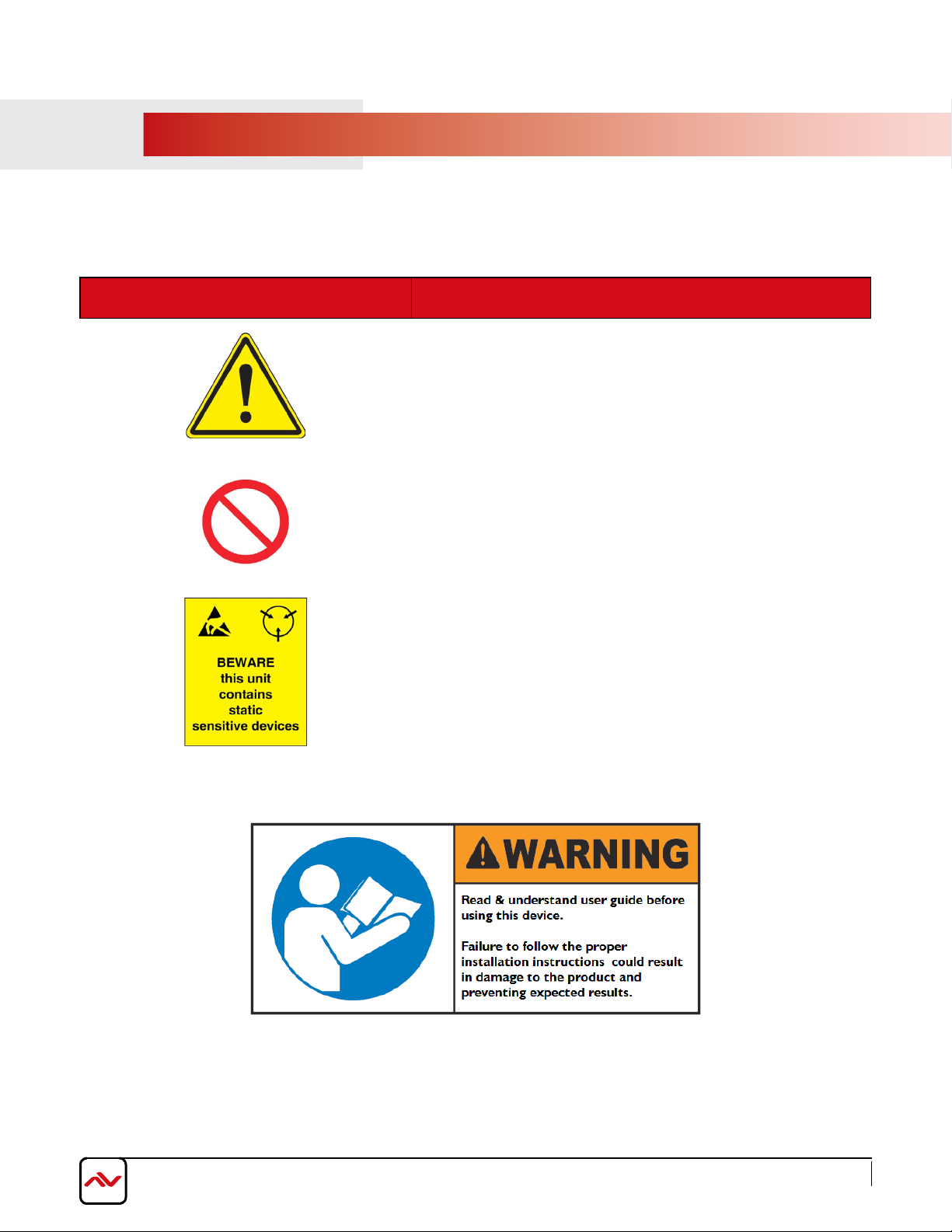
Warning symbols Description
ONLY USE THE PROVIDED
ADAPTER SUPPLIED. DO NOT TAMPER WITH THE
ELECTRICAL PARTS. THIS MAY RESULT IN ELECTRICAL
SHOCK OR BURN.
DO NOT TAMPER WITH THE UNIT. DOING SO WILL
VOID THE WARRANTY AND CONTINUED USE Of
THE PRODUCT.
THE VIDEO BOARDS ARE VERY
PLEASE ENSURE IF
A SURF
RACK MOUNTED OR INSTALLED ON
ACE, IT SHOULD BE IN A GROUNDED
ENVIROMENT.
POWER CABLE OR POWER
SENSITIVE TO STATIC.
2
Page 7
www.avenview.com
Page
2.
The Avenview AVXWALL is a modular chassis based 4K video wall Processor with first in its class FPGA and industry
recognized video processors built into the design.
The AVXWALL is compatible with standard definition (SD), Full HD (1080p), WQXGA (2160x1600) and 4K.
AVXWALL accepts 4K signal formats with modular input and output board design with video connectors such as Dual Link
DVI, DisplayPort and HDM which offers impeccable quality across multiple screens. The video wall processor also can mix
and match our line of I/O cards which can be installed into the appointed space. I/O cards are available in CVBS,YPbPr, VGA,
DVI, HDMI, SDI, DisplayPort, HDBASET and optical fiber. These I/O cards offer extremely high video bandwidth , which
ensures real-time signal processing, with no delay or frame loss.
No in-depth training is required to use our new Control Software. Creative and useful features for any client solution include
drag n drop, image placement, zoom, and user preset buttons to recall favorites. Bonus feature; our software can also
preview the input source directly within the Control Software which is connected through TCP/IP. Enjoy using your touch
devices with our optional MRCS controller board to manage multiple video walls and layouts with fully customizable interface.
It also supports a 2x2, 3x3, and 4x4 - upto max 72 outputs on a
The user can also create quad view grid format on a single display , PIP, Overlay across many displays with a click of the
mouse with user defined presets up to128 .
Having FPGA as its core design, this technology enables this unit to manage multiple Video Walls with one single processor.
The user has the ability to control each video-wall separately within the control software. The output resolution can also be
managed within each individual screen/monitor and also for different Video Walls.
INTRODUCTION
FEATURES:
- Modular input and output chasis design 720x480 to 4096x2160;
- Supports CVBS,YPbPr,VGA,DVI, HDMI, SDI, DisplayPort,UTP and optical fiber;
- Seamless Switching, No black fields or frame loss,
- Full screen modes PIP,PAP, Zoom, image crop and adjustable size & position through software;
- Functions perfectly as a multiviewer, video screen splitter, video converter and matrix switcher;
- Grid formating up to 4 Images per screen;
- Minimum single screen to 64 screens horizontally /32 screens vertically 600x800, 768x1024, 768x1024, 720x1280,
800x1280, 1024x1280, 768x1366, 768x1360, 1050x1400, 900x1440, 1200x1600, 1050x1680, 1080x1920, 1200x1920;
- IP camera decoding support (64 1080p and 265 D1 images) can be supported on the max chassis size;
- PC capture over the network @20 frames per sec;
- Image parameters and layouts are automatically saved in 128 Preset Mode of the device creating easy buttons;
- Up to 4 separate Background Image storage;
- Management of Multiple Videowalls with same inputs across many designs;
- EDID Management;
- Input Signal preview through Control Software @5 frames per sec;
- Software control through TCP/IP;
- Available in 2/4/8/13/19U chassis sizes.
3
Page 8
www.avenview.com
Page
2.1
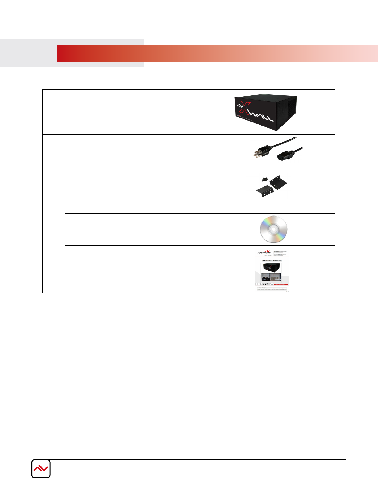
PACKAGE CONTENT
Before you start the installation of the converter, please check the package contents.
1
HDM-AVXWALL
POWER CORD
RACK-MOUNTING KIT
2
INSTALLATION SOFTWARE / CD
USER MANUAL
X 1
X 1
X 1
X 1
4
Page 9
www.avenview.com
Page
2.2 BEFORE INSTALLATION
•
Put the product in an even and stable location. If the product falls down or drops, it may cause an injury or malfunction.
• Don’t place the product in too high temperature (over 50°C), too low temperature (under 0°C) or high humidity.
•
Use the DC power adapter with correct specifications. If inappropriate power supply is used then it may cause a fire.
•
Do not twist or pull by force ends of the video cable. It can cause malfunction.
2.3
PANEL DESCRIPTION
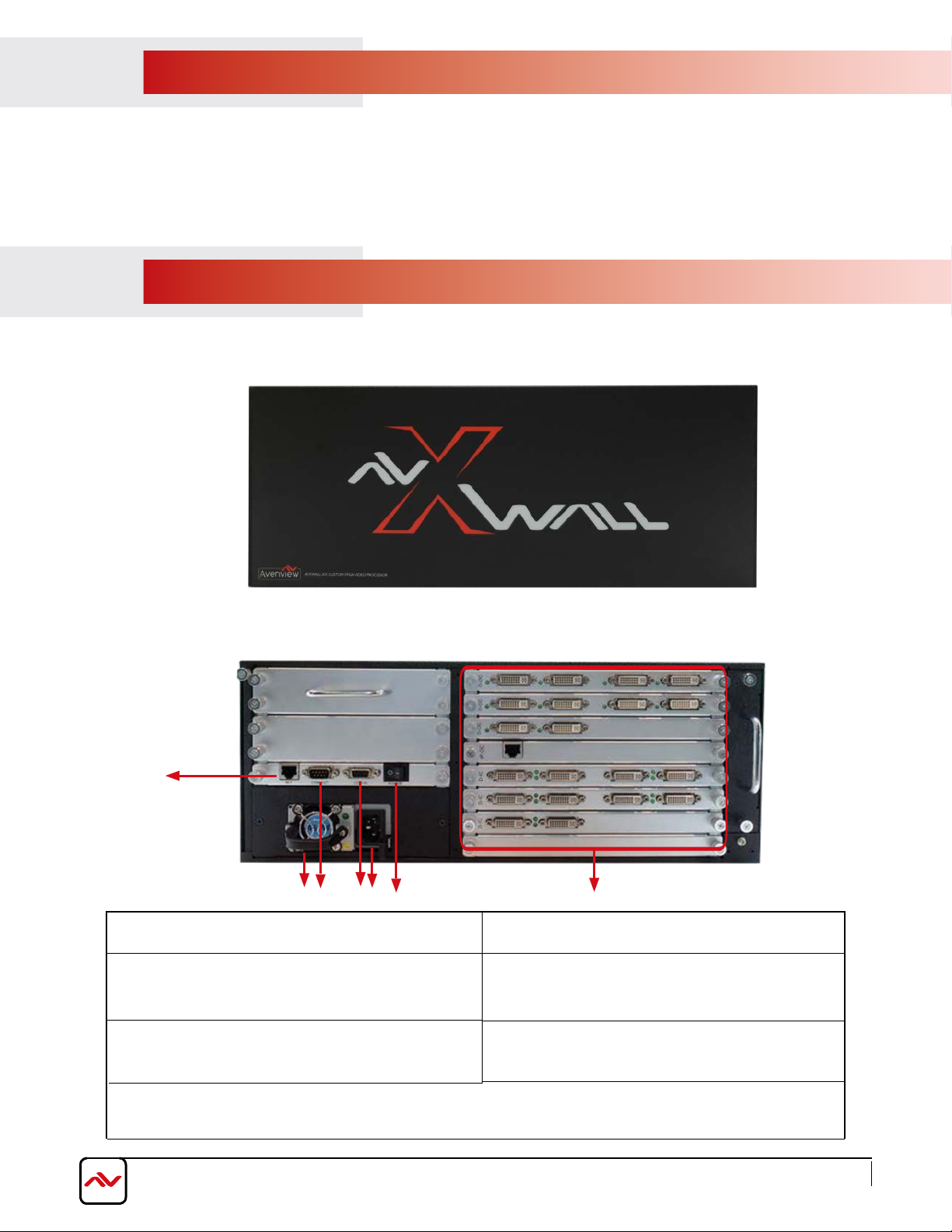
2.3.1 HDM-AVXWALL Front Panel
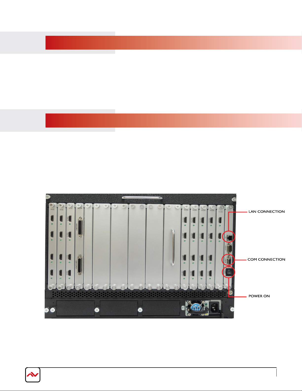
2.3.2 HDM-AVXWALL Rear Panel
1
2
3
1.
LAN: Connect to active network for LAN serving,
Telnet and Web GUI control (using Cat5/6 cables)
3.
RS 232 OUT: Connect to PC or control system with
D-Sub 9-pin cable for the transmission of RS-232
commands.
POWER OUTLET: Power cord connection interface
5.
INPUT AND OUTPUT CARDS: Supports up to 128 Inputs / 72 Outputs HDBaseT, HDMI, DVI, SDI,
7.
DP (see pages 10-14)
6
4
5
2. VENTILATION FAN: Automatically runs to keep
unit cool.
4.
RS 232 IN:RS-232: Connect to PC or control
system with D-Sub 9-pin cable for the transmission
of RS-232 commands.
POWER SWITCH ON/OFF: Powers the device
6.
On and OFF
7
5
Page 10
www.avenview.com
Page
3.
To setup Avenview HDM-AVXWALL follow the steps outlined below:
1.
2.
3.
4.
5.
6.
7.
INSTALLATION
Premium quality DVI, HDMI, VGA, Composite, S-Video cables and adapters are recommended.
Make sure HDM-AVXWALL is turned off.
Connect displays (or projectors, TV or other display devices) to output cards on the HDM-AVXWALL.
Connect the Source devices (such as, PC, DVD player, or Media player etc.) to HDM-AVXWALL input cards.
Connect a Windows based laptop or desktop (that will used to configure the HDM-AVXWALL) to HDM-AVXWALL
using RS-232 to USB Adapter cord.
Power ON HDM-AVXWALL.
Turn ON all devices connected to HDM-AVXWALL and then setup the HDM-AVXWALL from the system through
RS-232 to USB Adapter and provided Avenview software.
back
- DO NOT block the
the
unit
is
If
over-heat, which may result in system failure.
blocked it will block the air flow from the fans on the side of the unit. This could cause system to
of this device or stack another device on the top or bottom of the HDM-AVXWALL
6
Page 11
www.avenview.com
Page
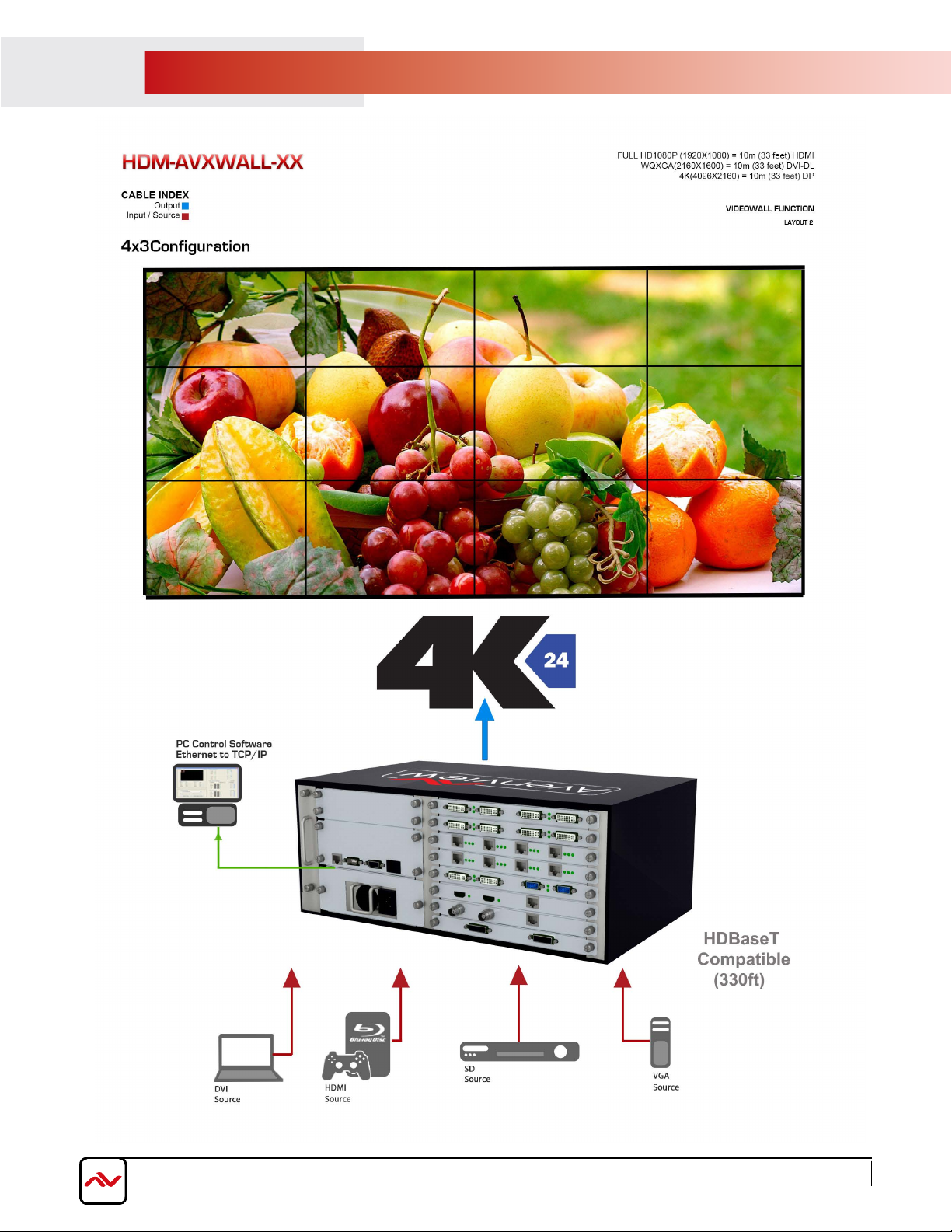
4.
APPLICATION DIAGRAM
7
Page 12
www.avenview.com
Page
5.
SOFTWARE
The Avenview HDM-AVXWALL includes Control Software program that requires Microsoft Windows XP or later.
Connect the provided RS-232 to the HDM-AVXWALL and any USB port on a Windows based computer that will be used to
configure the HDM-AVXWALL. When connected Windows will search for the required drivers. If an older version of
Windows operating system is used and windows was unable to find drivers; insert the Installation CD (provided) and have
Windows search for drivers.
5.1
OPERATION AND CONFIGURATION
1.
Power ON the HDM-AVXWALL.
2. Power ON all INPUT and OUTPUT connected devices.
8
Page 13
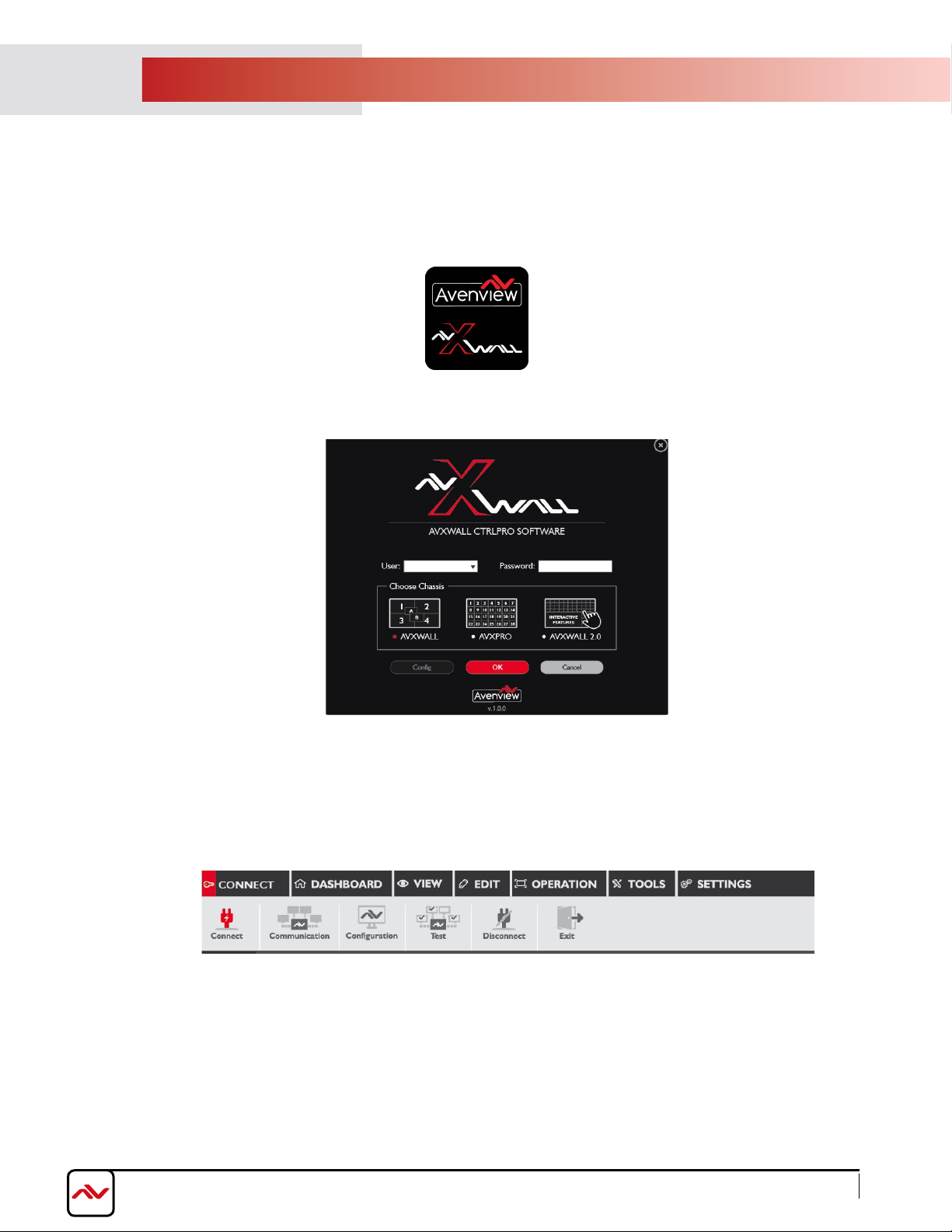
(A) CONNECT:
Establish Connection:
Launch application by double clicking the software icon on desktop
Login window pops up, Type ‘ADMIN’ as user name, password blank, then click
‘OK’.
Avenview control software menu consists of seven tabs:
'Connect', 'Dashboard', 'View', 'Edit','Operation', 'Tools', 'Settings.
Click ‘Connect’ tab to configure communication between HDM-AVXWALL and Control Software.
www.avenview.com
Page
9
Page 14
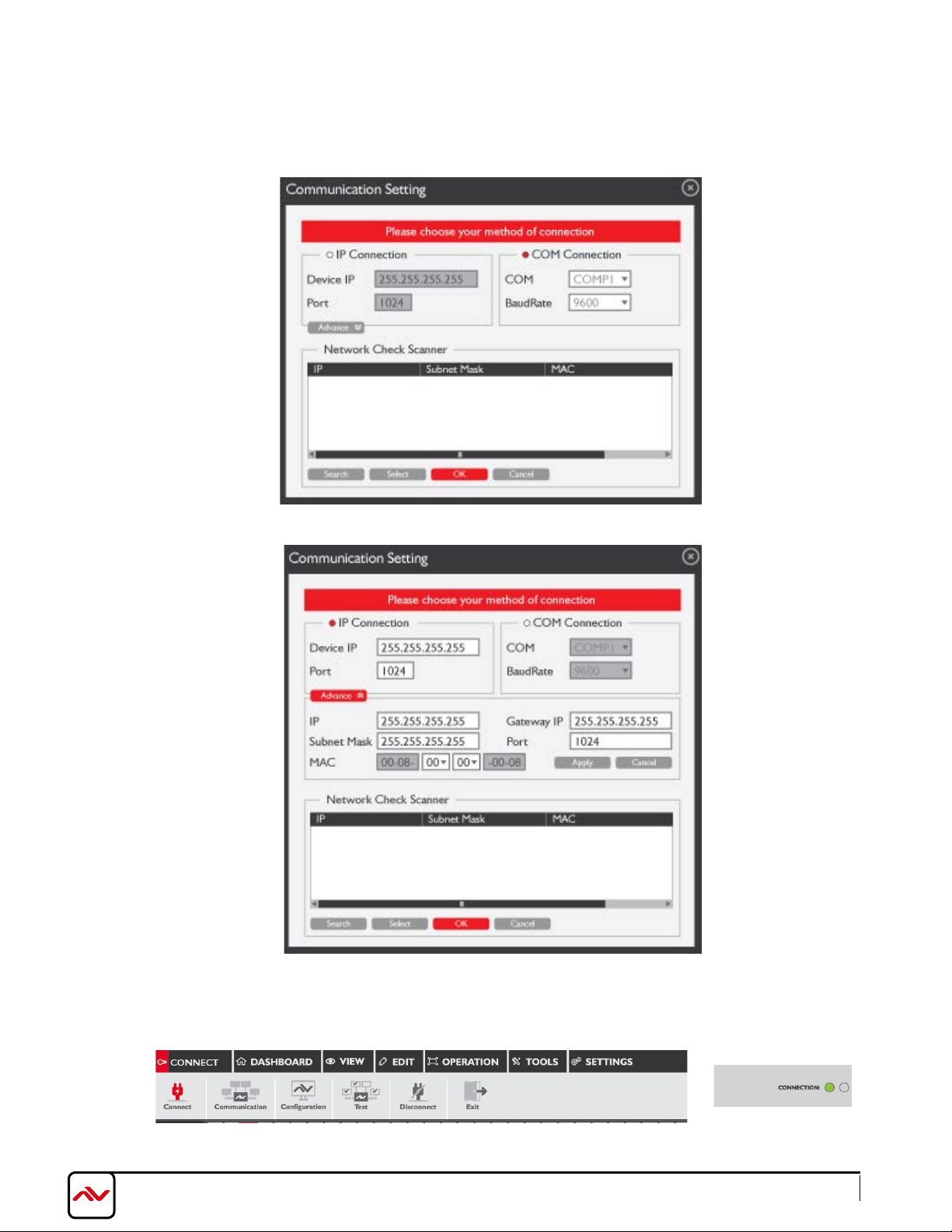
In 'Communication Setting' window two methods of communication can be used.
‘IP Connection’
If
and ‘1024’.
If
‘COM Connection’
Click OK to apply and save settings.
is selected, the default IP address and port number of the processor are ‘192.168.1.65’
is selected, Select the correct COM port. Baud rate is 9600.
Click 'Connect' to establish communication, Connection should light up green on the top right side section
of the software
www.avenview.com
Page 10
Page 15
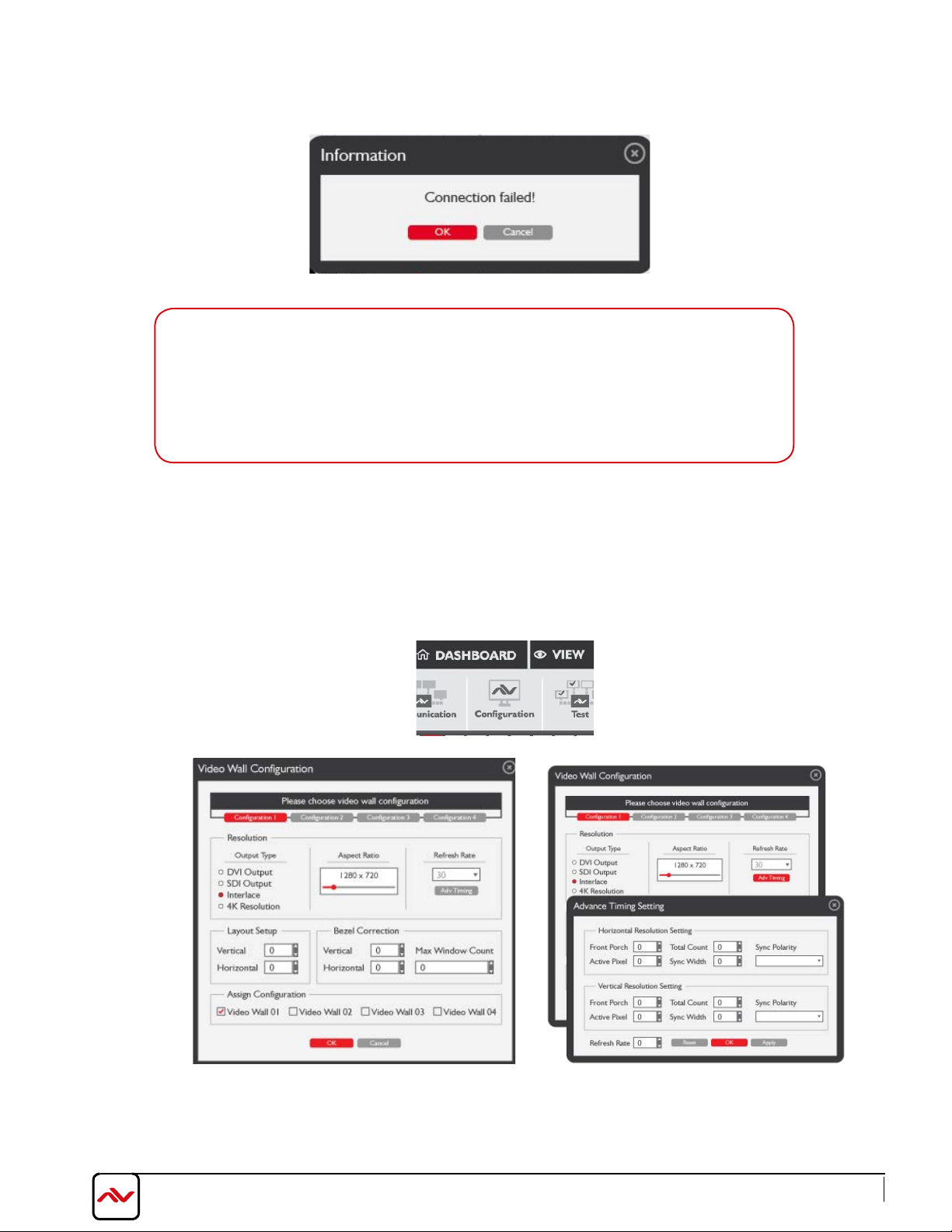
If communication settings are not correct a "Connection failed" error message will
pop-up. Please re-check communication settings and try again.
The possible reasons causing above error could be:
- No Power to
HDM-AVXWALL
the
- The serial connection is not well established. Please ensure that drivers are properly installed and all cables are
securely connected. Check device manager, and ensure that RS-232 to USB Adapter is assigned COM Port #
and there is no exclamation mark.
HDM-AVXWALL
or it is in sleep state. If this is the case, check the power and restart
Configuration
Click on "Configuration" from the top tabs menu. Users can set the output
resolutions, layout, aspect ratio and Bezel correction
video walls.
for up to 4 groups of connected
www.avenview.com
Page
11
Page 16
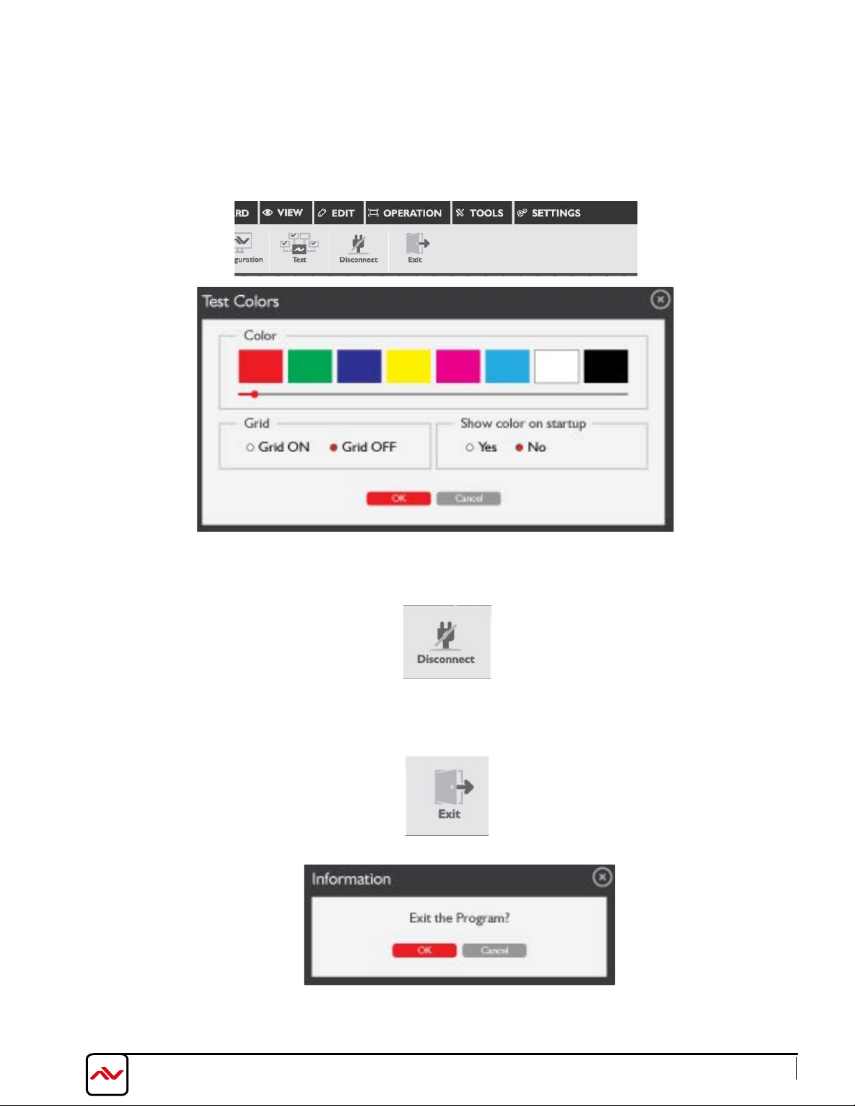
Test Signal
'Test' tab allows users to test the connection between processor and displays by
transmitting signals of pure colour or grid to the displays.
Click 'Disconnect' to disconnect the connection between the Processor and Control Software
Click 'Exit' to exit and close PC control software
www.avenview.com
Page
12
Page 17
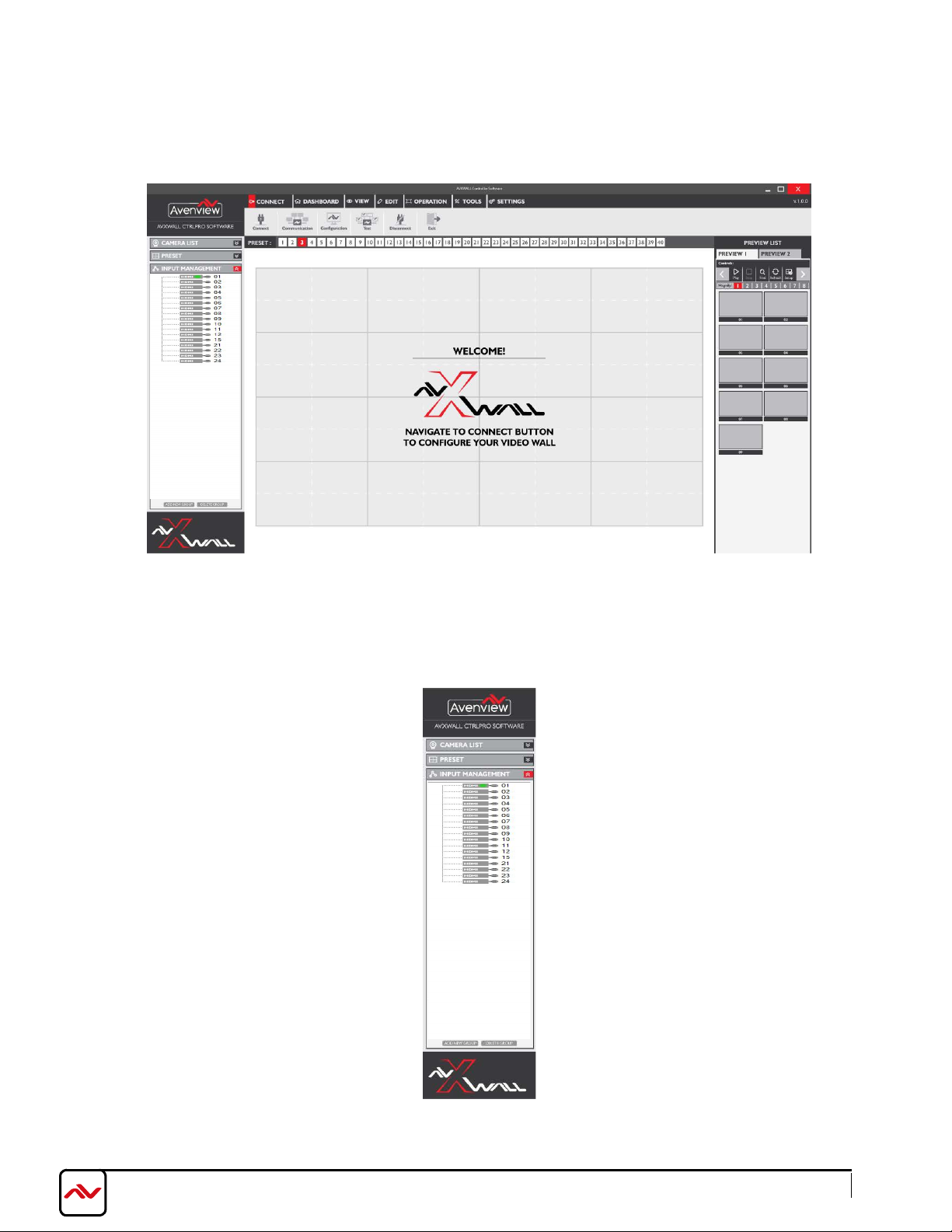
Input Management
The signal source list is located on the left panel of the software UI. Input source will turn green when
input signal is detected on the corresponding channel.
Advanced Settings including rename and modify of any Source can be accessed by right clicking on any of
the source list icon.
www.avenview.com
Page
13
Page 18
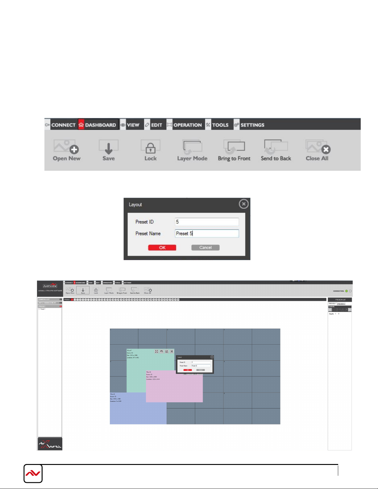
(B) DASHBOARD:
1. Presets
Saving and Loading Presets
Click on "Dashboard"
Click "Save" to save the created Video wall including layout, size and source windows
Click "Open" to load the created Video wall including layout, size and source windows
Layouts can be saved with a unique ID and name to be easily recalled
www.avenview.com
Page
14
Page 19
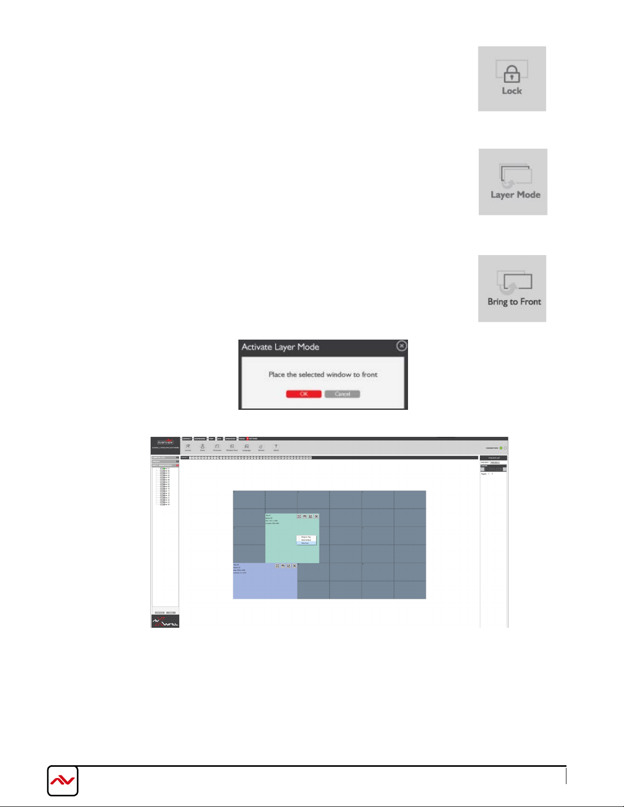
"Lock" Locks open layout windows
"Layer Mode" allows control over multiple open windows on the video wall
on the video wall from being controlled
"Bring to Front" moves the selec
Right Click on any layout windows to send to front, send to back or
Maximize the selected input.
ted window in the video wall to front.
www.avenview.com
Page
15
Page 20
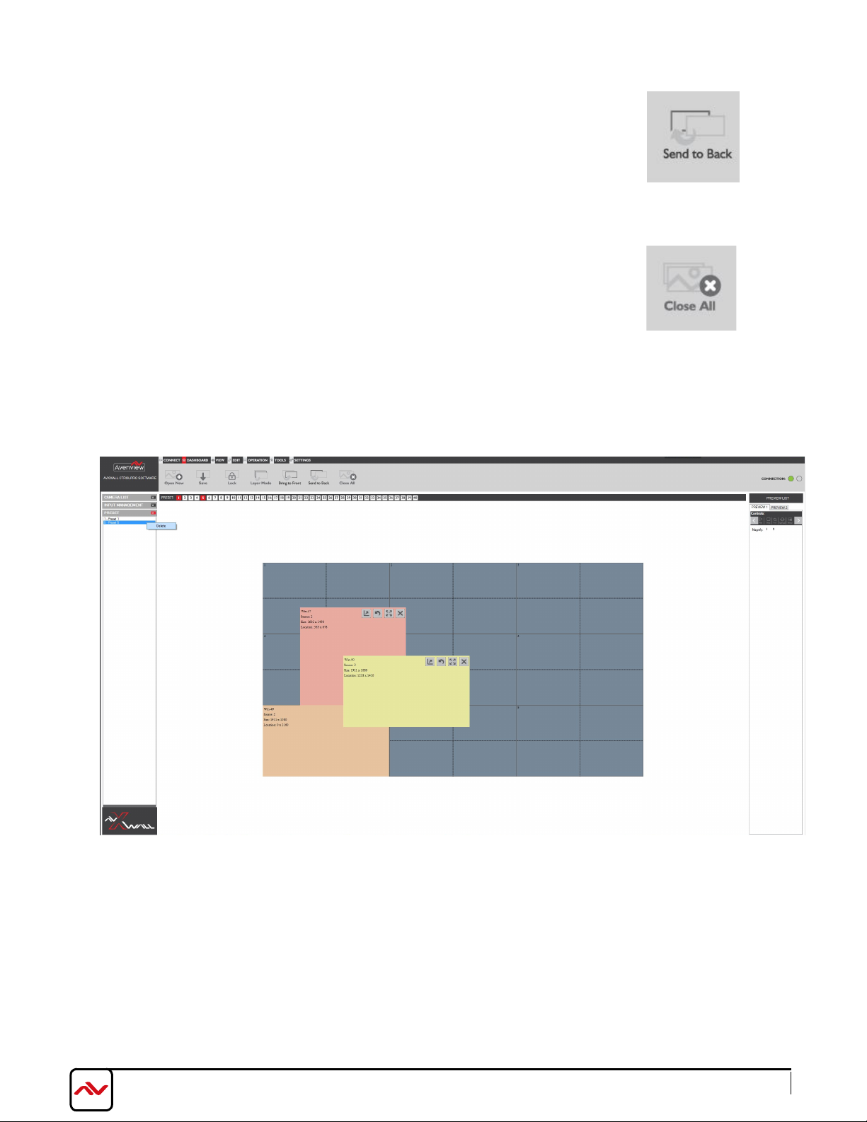
"Send to Back" moves the selected window in the video wall to back
"Close All" closes all open windows of the video wall
To delete presets: Right Click on saved presets and select delete
www.avenview.com
Page
16
Page 21
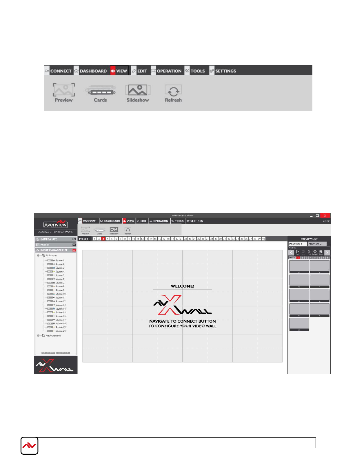
(C) VIEW:
"P
review" Launches preview column on the r
clicking the “play” button. The input signal can be previewed in a larger window by double clicking each
preview window.
- Play: Plays sources in preview list
- Stop: Stops playing preview list
- Find: Searches for specific preview window
- Refresh: Refresh the preview list
- Setup: Modify the preview list resolution and IP address
ight side of the software UI. User can preview the input signal by
www.avenview.com
Page
17
Page 22
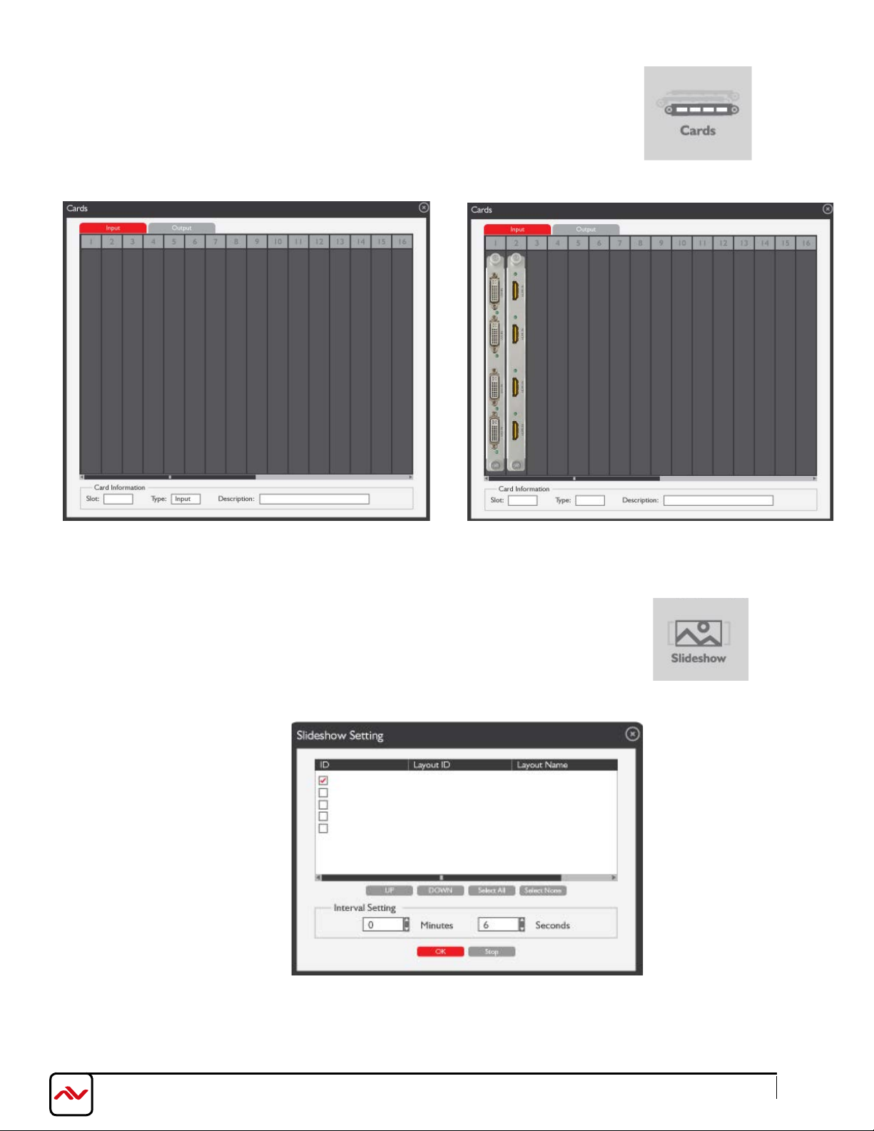
"Cards" Displays input/output cards installed and slots occupied
"Slideshow" Controls auto play of preset layouts in loop with cutomized
interval settings
www.avenview.com
Page
18
Page 23
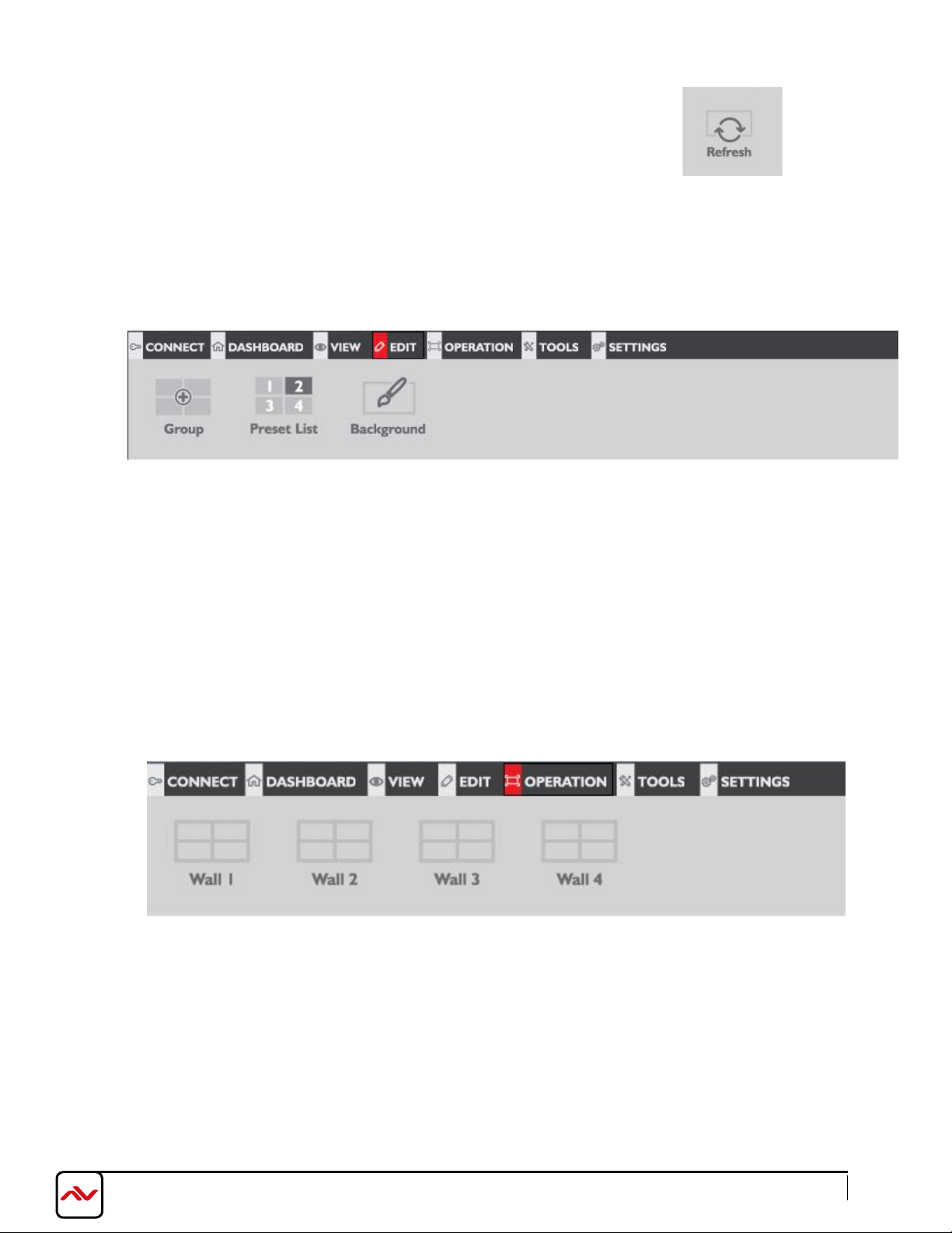
"Refresh" Refreshes the displayed video wall
(D) EDIT:
"Group" Allows arrangement of display screens in the software to match physical arrangement of
displays
"Preset List" Allows editing of preset layouts
"Background" Allows adding a background image (.bmp) to the video wall to be displayed when
no video signal is displayed.
(E) OPERATION:
The HDM-AVXWALL supports up to 4 separate video wall setups to be controlled from this same software
Selecting any of "Wall 1, Wall 2, etc..." displays the preconfigured video wall configuration
www.avenview.com
Page
19
Page 24
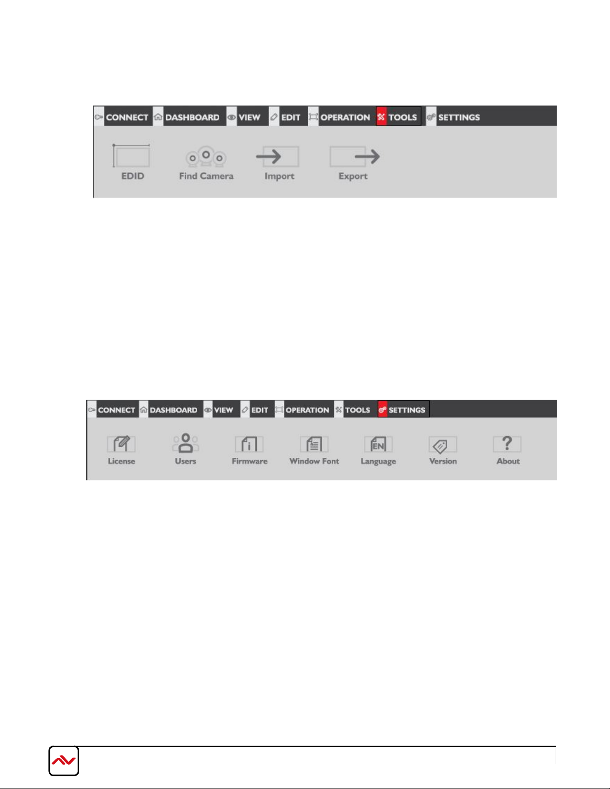
(F) TOOLS:
"EDID" Allows display identification to sources connected by learning modes
"Find Camera" Adds IP cameras and modify IP settings
"Import":
"Export" Allows exporting of presets and layout configurations into a file to be used for easy
future configurations or with other connected video walls
Allows importing of previously saved file of presets and layout configurations
(G) SETTINGS:
"License": Displays software license and copyrights agreement
"Users": Controls user names and passwords
"Firmware": Displays device firmware information
"Window Font": Changes in software font size
"Language": Choose different languages
"Version": Displays software version
"About": Display information about software, device and Avenview
(more languages will be supported in future)
www.avenview.com
Page
20
Page 25
www.avenview.com
Page
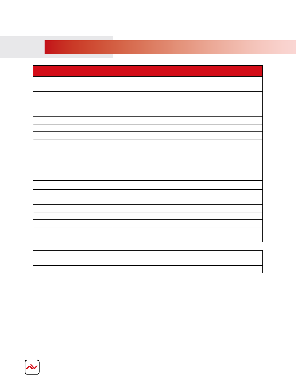
6. SPECIFICATIONS
Item Description
MODEL
UNIT DESCRIPTION Multi-Input Image Video Wall processor with 4K support
VIDEO FORMAT SUPPORT
LOCAL OUTPUT Yes - DVI
SUPPORTED RESOLUTIONS SD Up to 1080p, 4K (4096x2160@24Hz)
AUDIO SUPPORT No
SYSTEM CONTROL TCP/IP
ESD PROTECTION
I
NPUT CONNECTORS
OUTPUT CONNECTORS
RCA CONNECTOR 75Ω female
DVI CONNECTOR DVI-I (212-pin female, digital only)
RJ45 CONNECTOR WE/SS 8p8C with 2 l ED indicators
RS232 CONNECTOR DE-12 (12-pin D-sub f emale)
DIMENSIONS (L X W X H) Unit: Based on Form factor
DIMENSIONS (L X W X H) Package: Based on Form Factor
POWER SUPPLY AC 100-240V
POWER CONSUMPTION 60 Watt (max)
CVBS,YPbPr,VGA,DVI, HDMI, SDI, DisplayPort,UTP and
- Human body model — ±15kV (air-gap discharge) &
±8kV (contact discharge) - Core chipset — ±8kV
HDM-AVXWALL
optical fiber
See Pages 10-14
See Pages 10-14
Environmental
OPERATING TEMPERATURE 32˚ ~ 104˚F (0˚ to 40˚C)
STORAGE TEMPERATURE -4˚ ~ 140˚F (-20˚ ~ 60˚C)
RELATIVE HUMIDITY 20~120% RH (no condensation)
21
Page 26
www.avenview.com
Page
7.
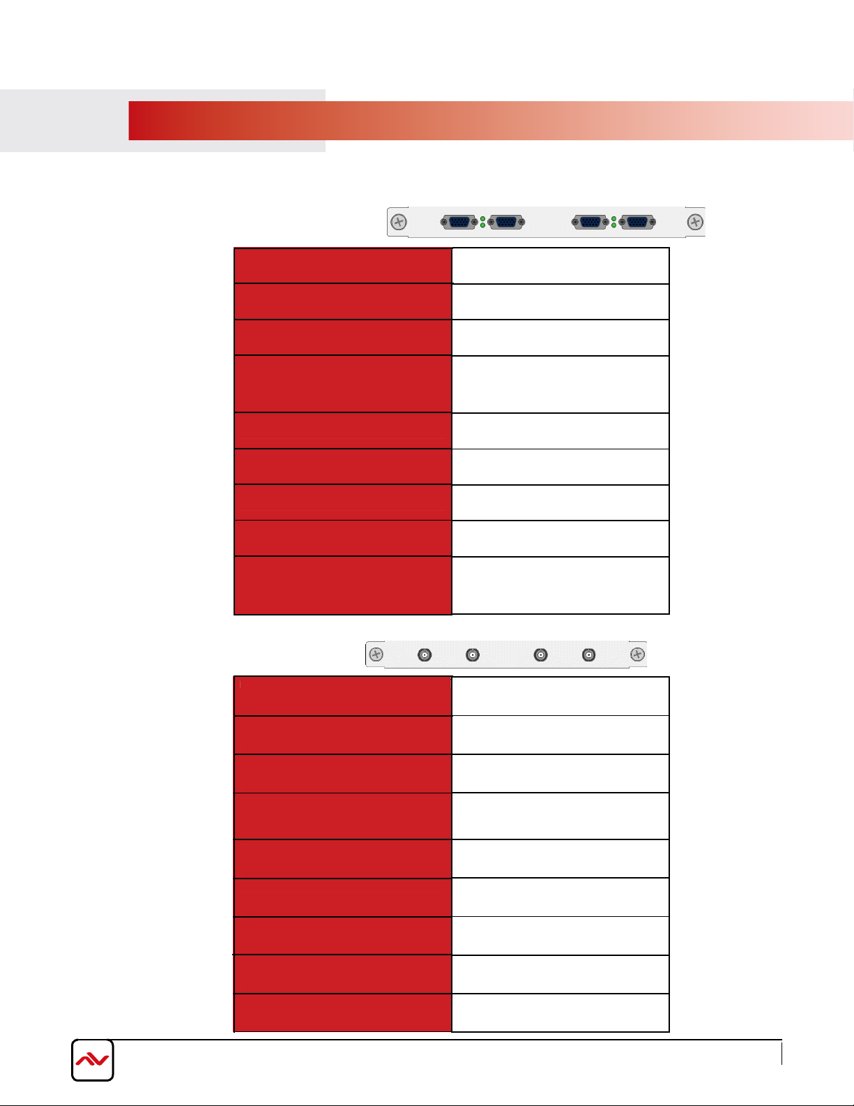
INPUT / OUTPUT CARDS
7.1 Input cards
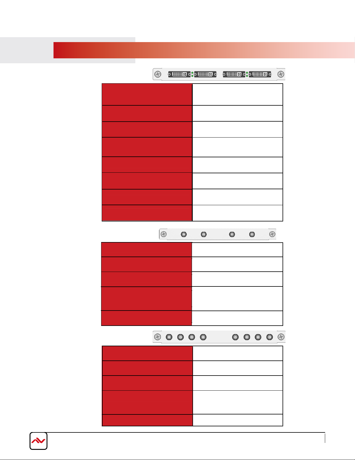
7.1.1 Input Port - VGA
Signal Format
Maximum Resolution
Horizontal Scanning Ration
Synchronization
Customised EDID
Reference Level
Physical Port
7.1.2 Input Port - YPbPr
Color Depth
Impedance
RGBHV
1920*1200
32bits/pixel
15KHz-90KHz
Separate sync
YES
75Ω
0.7Vp-p
RGB: 15pins D-sub(DB15/DE-
15F)
Signal Format
Maximum Resolution
Color Depth
Horizontal Scanning Ration
Synchronization
Customised EDID
Impedance
Reference Level
Physical Port
Component EIA-770.2-A
1920*1080
32bits/pixel
15KHz-90KHz
Separate sync
YES
75Ω
0.7Vp-p
RCA*3
22
Page 27
www.avenview.com
Page
7.1.3 Input Port - DVI
Signal Format
Maximum
Color Depth
Signal Level
Customised EDID
Maximum Data Rate
7.1.4 Input Port - CVBS
Resolution
Impedance
Physical Port
Standard
DVI-D digital T.M.D.S. signal in
DVI 1.0
1920*1200
32bits/pixel
T.M.D.S 2.9V-3.3V
YES
50Ω
4.95Gbps
24+5 pins/DVI-I
PAL/NTSC
Reference Level
7.1.5 Input Port - SDI
Resolution
Impedance
Physical Port
Signal Format
Resolution
Impedance
Maximum Data Rate
Physical Port
480i/576i
75Ω
1Vp-p
BNC
HD/3G-SDI
720p/1080p
75Ω
3Gbps
BNC
23
Page 28
www.avenview.com
Page
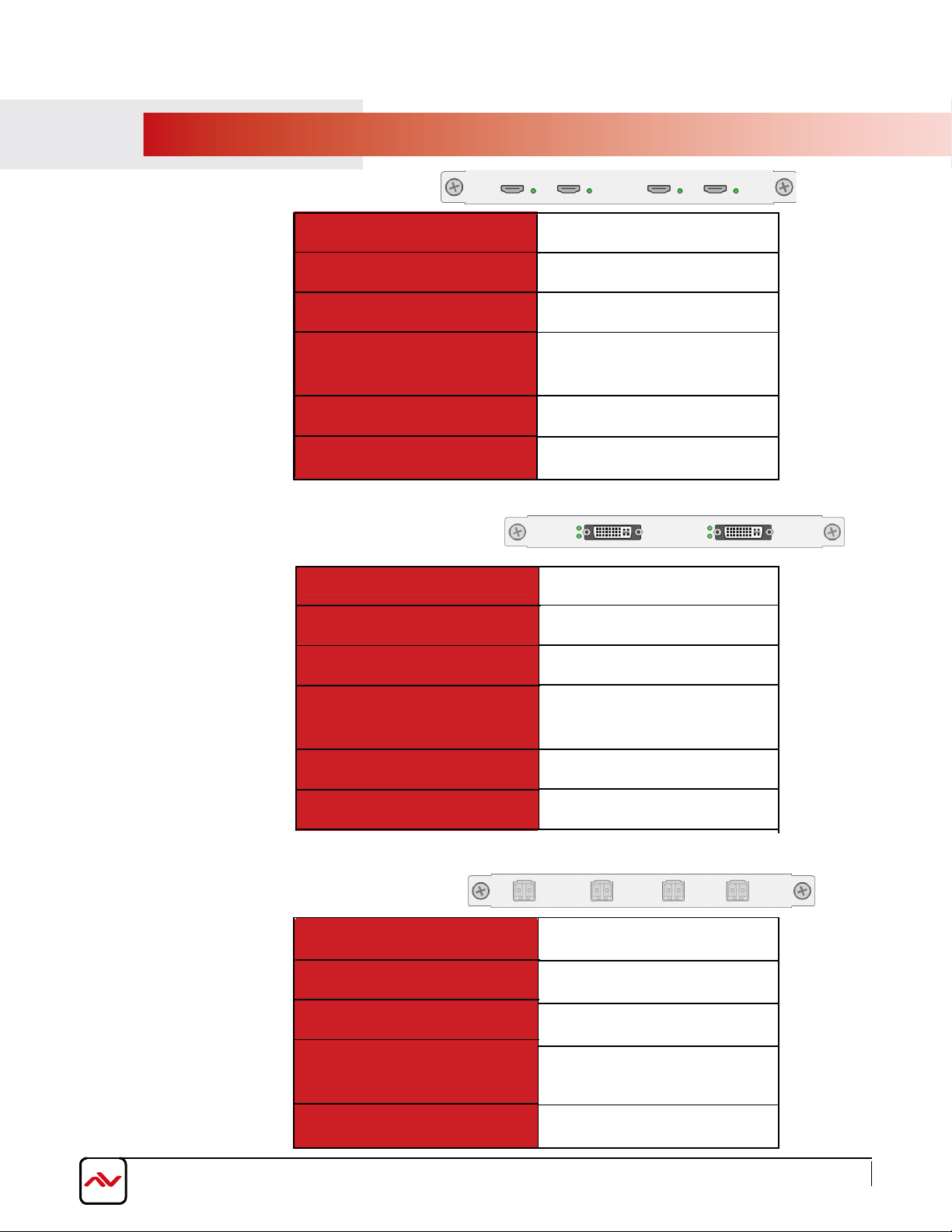
7.1.6 Input Port - HDMI
Standard
Maximum Resolution
HDCP
Customised EDID
Maximum Data Rate
Physical Port
7.1.7 Input Port - Dual-link DVI
Signal Format
Maximum Resolution
Impedance
HDMI 1.3
1920*1200
Yes
YES
4.95Gbps
HDMI Type A
Dual-link DVI
4K*4K
50Ω
Customised EDID
Maximum Data Rate
Physical Port
7.1.8 Input Port - Optical Fibre
Signal Format
Maximum Resolution
Front-end Device
Maximum Transmission
Distance
Physical Port
YES
9.9Gbps
24+5 pins/DVI-I
Single mode optical signal
1920*1200
TriF-T1SD or TriF-T1SG
10km
LC
24
Page 29
www.avenview.com
Page
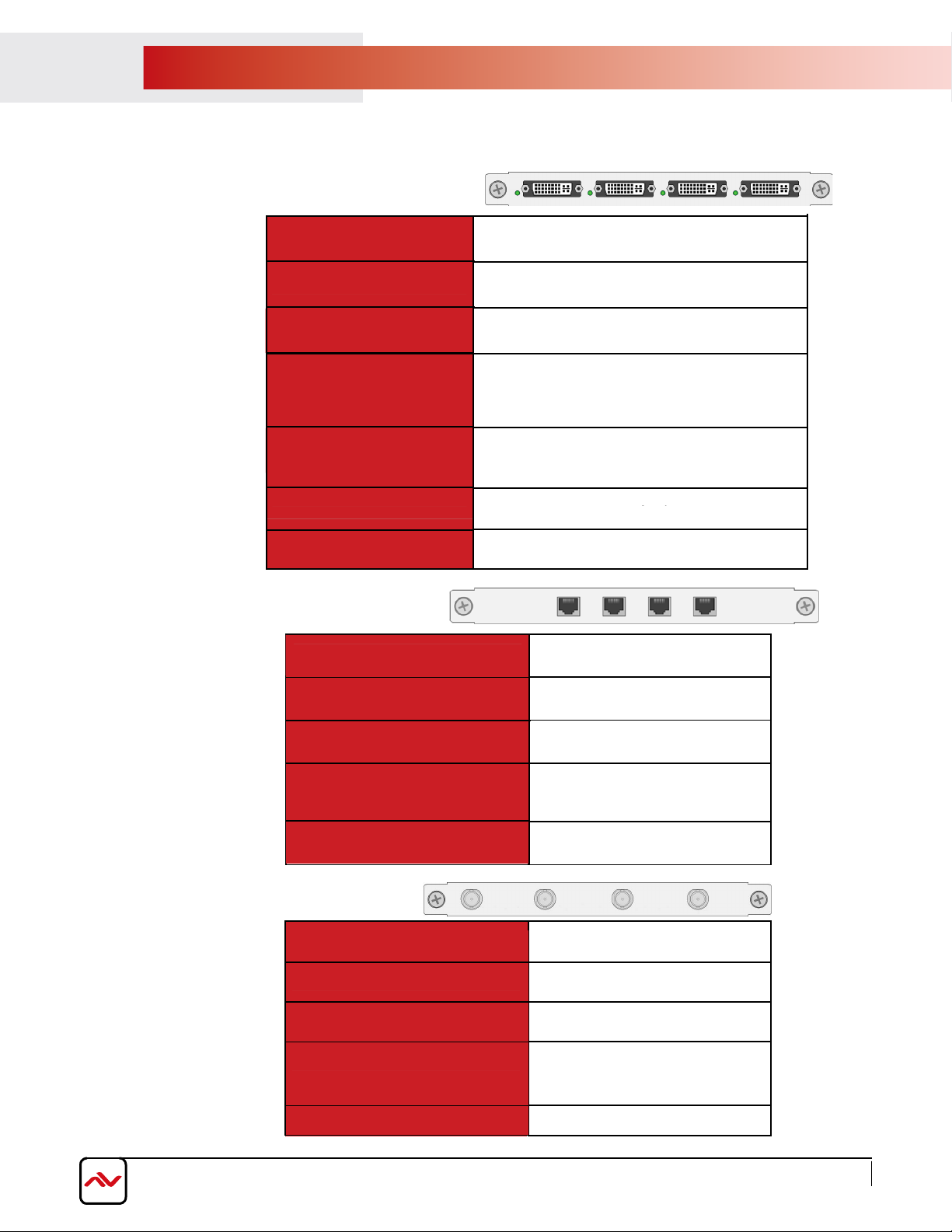
8.2 Output cards
7.2.1 Output Port - DVI/VGA
Signal Format
Maximum Resolution
Color Depth
Maximum
Transmission Distance
Physical Port
Signal Level
Impedance
7.2.2 Output Port - Twisted Pair
Signal Format
DVI-I in DVI 1.0 standard
1920*1200
32bits/pixel
25m(DVI)
24+5 pins/DVI-I
(Adapter required for VGA
output)
T.M.D.S. 2.9V-3.3V
50Ω
Twisted pair differential signal
Maximum Resolution
Maximum Transmission
Physical Port
7.2.3 Output Port - SDI
Signal Format
Output Backup
Physical Port
Color Depth
Distance
Resolution
Impedance
1920*1200
32bit/pixel
100m
LC
HD-SDI/3G-SDI
720p/1080p
75Ω
Yes
BNC
25
Page 30
www.avenview.com
Page
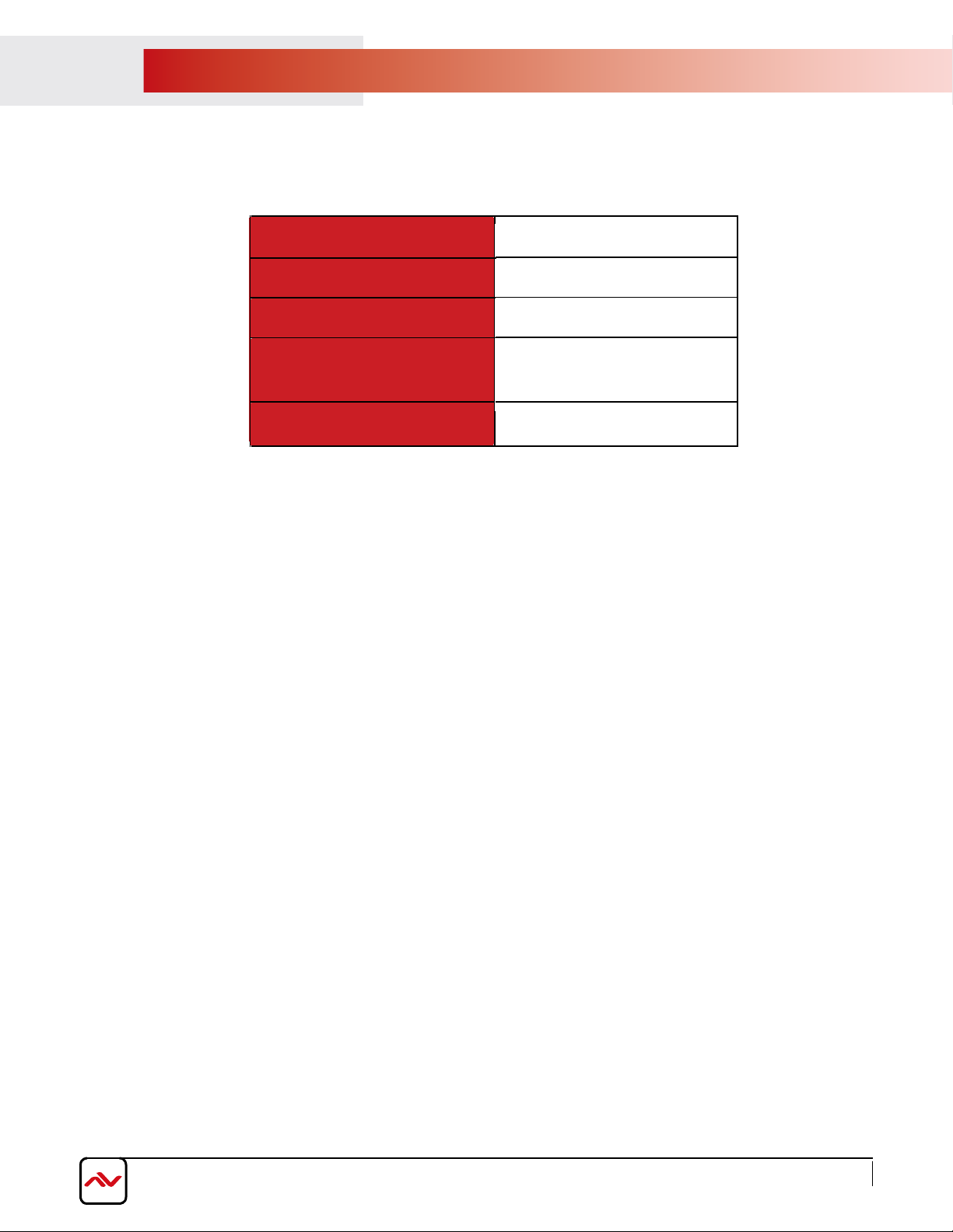
7.2.4 Output Port - Optical Signal
Signal Format
Maximum Resolution
Rear-end Device
Maximum Transmission
Distance
Physical Port
Single mode optical signal
1920*1200
FO-DP/HDM4K-300EMIX
10km
SC
26
Page 31
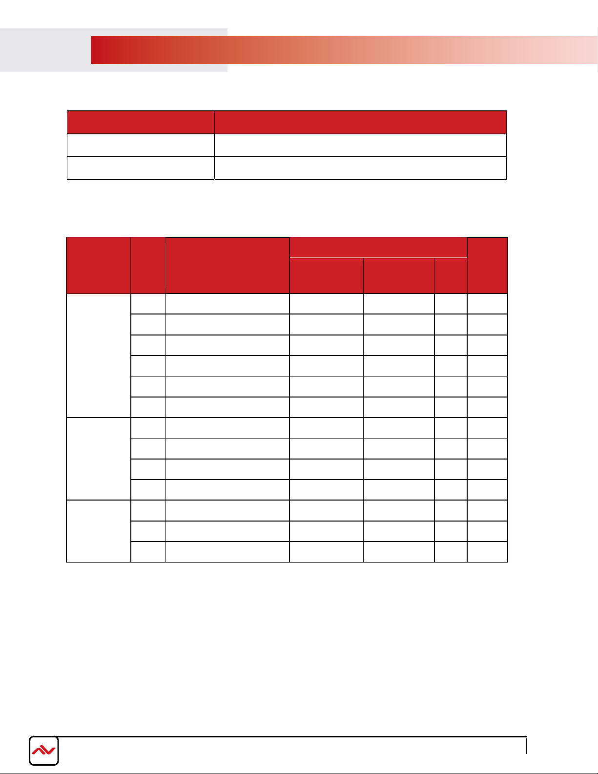
8. Models and Scales
Models Features
Video-Wall Processor I Two windows per screen
Video-Wall Processor II Four windows per screen
Models
Video-Wall
Processor I
Video-Wall
Processor II
Dimension (mm) Scales
DVI/VGA/HDMI/S
DI/YPbPr/Optical/
T wisted-pair
2U 438(W)*300/316(D)*89(H) 8 4 32 8
4U 438(W)*300/316(D)*178(H) 16 8 64 16
8U 438(W)*300/316(D)*356(H) 32 16 128 36
14U 438(W)*300/316(D)*623(H) 64 32 256 72
20U 438(W)*300/316(D)*890H) 128 N/A 512 72
28U 438(W)*300/316(D)*1246(H) 128 36* 512 144
4U 438(W)*300/316(D)*178(H) 24 4* 96 8
8U 438(W)*300/316(D)*356(H) 52 8* 208 18
96 16* 384 36 14U 438(W)*300/316(D)*623(H)
22U 438(W)*300/316(D)*979(H)
2U 438(W)*300/316(D)*89(H) 8 4 32 4
128 36* 512 72
Dual-link DVI CVBS
Output Input
4U 438(W)*300/316(D)*178(H) 16 8 64 8
8U 438(W)*300/316(D)*356(H) 32 16 128 18
* means dual-link dvi input cards are only effective in specified input slots
ww
w.avenview.com
Page 27
Page 32
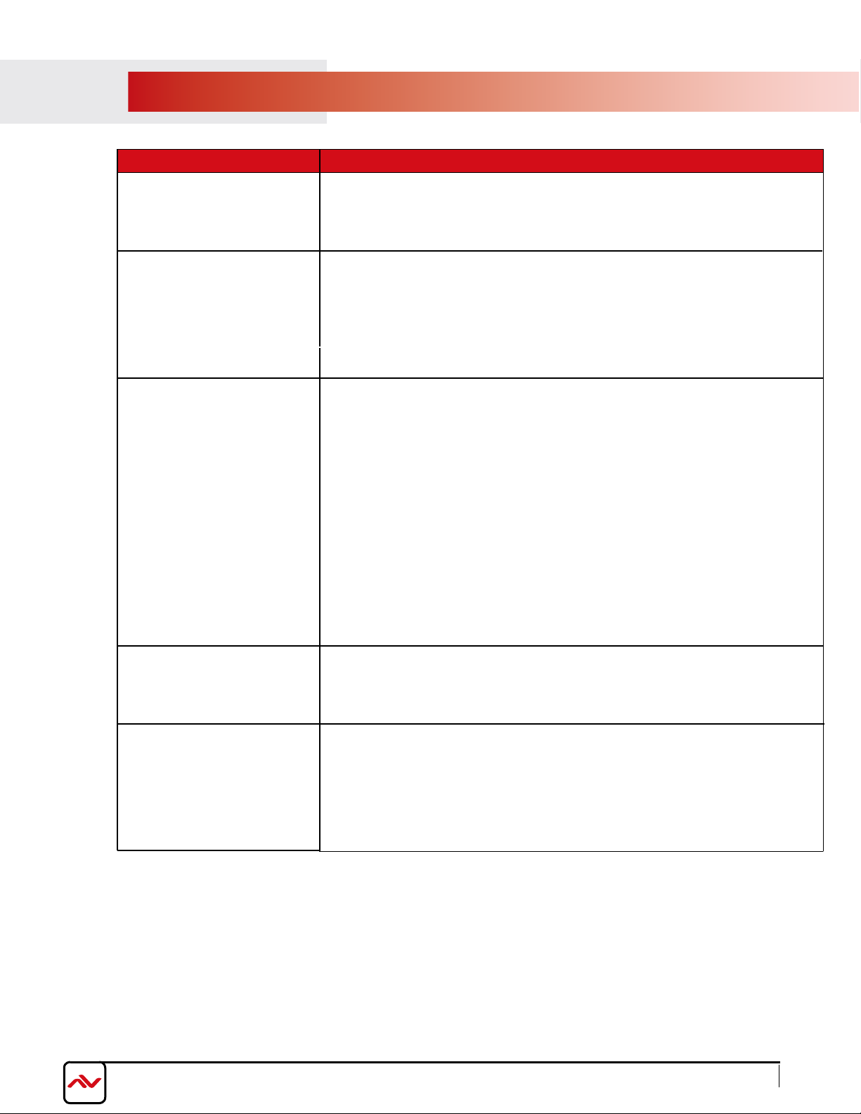
GENERAL TROUBLESHOOTING
9.
PROBLEM POSSIBLE SOLUTION
•
Missing VC++ runtime library
Cannot install software
No Image
Color cast on image
•
For 32 bits system, please install vcredist_x86.exe
•
For 64 bits system, please install vcredist_x64.exe
•
Please check the input signal
Make sure the each output and input port connected to the
•
corresponding device.
Use high quality video cables
•
Check output cable for any damage or exceed transmission distance
•
•
Check if cable is connected properly.
•
Check if cable is damaged.
Check software color adjustment.
•
Check display color adjustment.
•
•
Check port screws if tightened.
Shaking or
noise on image
Dark edge on the
display
•
Use premium quality video cables
•
Adjust the color balance of the display.
Re-adjust the color tune by controlling software
•
•
Check cable length, long cable causes serious signal attenuation signal
Check source if unstable or damaged cables connected
•
Check if video signal has been cropped by the display
•
•
Check if Inappropriate adjustment of the video is made on the
controlling software
•
Reset settings to Default using control software, then re-adjust to
desired configurations.
www.avenview.com
Page 28
Page 33
www.avenview.com
Page
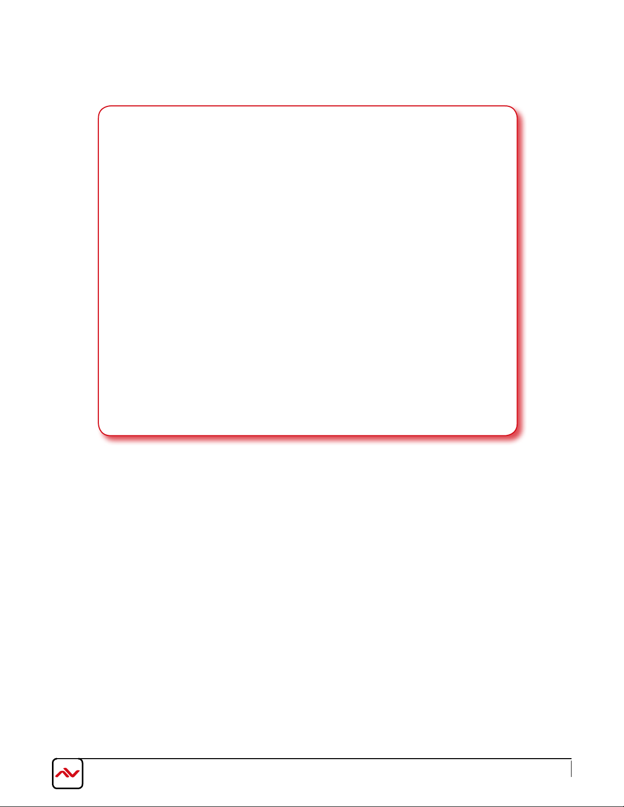
Notice
1. If the DVI or HDMI device requires the EDID information, please use EDID Reader/Writer to
retrieve and provide DVI/HDMI EDID information.
2. All HDMI over CAT5 transmission distances are measured using Belden 1583A CAT5e 125MHz
LAN cable and ASTRODESIGN Video Signal Generator VG-8512C.3
3. The transmission length is largely affected by the type of LAN cables, the type of HDMI sources,
and the type of HDMI display. The testing result shows solid LAN cables (usually in bulk cable
300m or 1000ft form) can transmit a lot longer signals than stranded LAN cables (usually
in patch cord form). Shielded STP cables are better suit than unshielded UTP cables. A solid
UTP CAT5e cable shows longer transmission length than stranded STP CAT6 cable. For long
extension users, solid LAN cables are your only choice.
4. EIA/TIA-568-B termination (T568B) for LAN cables is recommended for better performance.
5. To reduce the interference among the unshielded twisted pairs of wires in LAN cable, you can
use shielded LAN cables to improve EMI problems, which is worsen in long transmission.
6. Because the quality of the LAN cables has the major effects in how long transmission distance will
be made and how good is the received display, the actual transmission length is subject to your
LAN cables. For resolution greater than 1080i or 1280x1024, a CAT6 cable is recommended.
7. If your HDMI display has multiple HDMI inputs, it is found that the first HDMI input [HDMI
input #1] generally can produce better transmission performance among all HDMI inputs.
29
Page 34

www.avenview.com
Page
Notes
30
Page 35
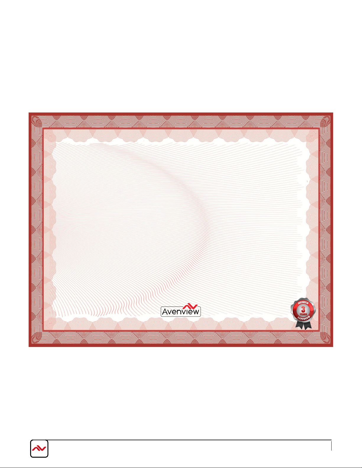
Avenview Warranty Certificate
AVENVIEW CORP. (“Avenview”) warrants Avenview-branded product(s) contained in the original packaging against defects in materials and workmanship when used
normally in accordance with Avenview's enclosed manual guidelines for a period of THREE (3) YEARS from the date of original retail purchase - Warranty Period. Avenview’s
published guidelines include but are not limited to information contained in technical specifications, user manuals and service communications.
LABOR: During the Warranty Period of THREE (3) YEARS, Avenview will repair or replace the product(s) at no cost using new or used parts equivalent to novel performance
and reliability if the product(s) is determined to have abide by Avenview’s published guidelines. Cost of Labor applicable to product(s) after Warranty Period. For labor costs,
please contact [email protected].
PARTS: During the Warranty Period of of THREE (3) YEARS, Avenview will supply new or rebuilt replacements in exchange for defective parts of the product(s) at no cost if
the product(s) is determined to have abide by Avenview’s published guidelines. Cost of Parts applicable to product(s) after Warranty Period. For part(s) costs, please contact
To obtain Warranty: (a) proof of purchase in the form of a bill of sale or receipted invoice reflecting that the registered product(s) is within warranty period must be presented
to obtain warranty service; (b) product(s) must be registered at time of purchase. Failure to do so will result in applicable parts and labor charges. Returning product(s) must
be shipped in Avenview’s original packaging or in packaging pertaining equal degree of protection to Avenview’s. Both Avenview and purchaser are responsible for freight
charges and brokerages when shipping the product(s) to the receiver.
NOT COVERED BY THIS WARRANTY
This warranty does not apply to any non-Avenview branded product(s); non-registered Avenview product(s). This warranty does not apply: (a) to cosmetic damage, including
but not limited to scratches, dents and broken cords; (b) to damage caused by use with another product; (c) to damage caused by accident, abuse, misuse, liquid contact, fire,
earthquake or other external cause; (d) to damage caused by operating the Avenview product(s) outside Avenview’s manuals or guidelines; (e) to damage caused by service
performed by anyone who is not a representative of A venview or an Avenview authorized personnel; (f) to defects caused by normal wear and tear or otherwise due to the
normal aging of the Avenview product(s), or (g) if any serial number has been removed or defaced from the Avenview product(s).
AVENVIEW IS NOT LIABLE FOR DIRECT, SPECIAL, INCIDENTAL OR CONSEQUENTIAL DAMAGES RESULTING FROM ANY BREACH OF WARRANTY OR
CONDITION, OR UNDER ANY OTHER LEGAL THEORY, INCLUDING BUT NOT LIMITED TO LOSS OF USE; LOSS OF REVENUE; LOSS OF ACTUAL OR
ANTICIPATED PROFITS (INCLUDING LOSS OF PROFITS ON CONTRACTS); LOSS OF THE USE OF MONEY; LOSS OF ANTICIPATED SAVINGS; LOSS OF BUSINESS;
LOSS OF OPPORTUNITY; LOSS OF GOODWILL; LOSS OF REPUTATI ON; LOSS OF, DAMAGE TO, COMPROMISE OR CORRUPTION OF DATA; OR ANY INDIR ECT
OR CONSEQUENTIAL LOSS OR DAMAGE REPAIR OR REPLACEMENT AS PROVIDED UNDER THIS WARRANTY IS THE EXCLUSIVE REMEDY OF THE CONSUMER.
Some states do not allow the inclusion or limitation of incidental or consequential damages, or allow limitations on duration implements of the Warranty Period; therefore the above limitations or
exclusions may not be applicable to you. This warranty gives you specific legal rights, and you may have other rights which vary from state to state.
1100 Military Road, Kenmore, NY 14217
1.866.508.0269
www.avenview.com
Page 36
Control Your Video
TECHNICAL SUPPORT
USA Head Office
Avenview Corp.
1100 Military Road
Kenmore, NY 14217
Ph: (866) 508 0269
Fax: (866) 387 8764
Email: [email protected]
Disclaimer
While every precaution has been taken in the preparation of this document, Avenview Inc. assumes no liability with respect to the operation or use of
Avenview hardware, software or other products and documentation described herein, for any act or omission of Avenview concerning such products or this
documentation, for any interruption of service, loss or interruption of business, loss of anticipatory profits, or for punitive, incidental or consequential damages
in connection with the furnishing, performance, or use of the Avenview hardware, software, or other products and documentation provided herein.
Avenview Inc. reserves the right to make changes without further notice to a product or system described herein to improve reliability, function or design.
With respect to Avenview products which this document relates, Avenview disclaims all express or implied warranties regarding such products, including but
not limited to, the implied warranties of merchantability, fitness for a particular purpose, and non-infringement.
Canada Sales
Avenview
151 Esna Park Drive, Units 11 & 12
Markham, Ontario, L3R3B1
Phone: 1.905.907.0525
Fax: 1.866.387.8764
Email: [email protected]
Avenview Europe
Email: [email protected]
Avenview Hong Kong
Email: [email protected]
 Loading...