

Page 1
www.avenview.com
1
FO-DVI-XX-MM Series
Models
FO-DVI-XX-MM
User’s Guide
© 2008 Avenview Inc. All rights reserved.
The contents of this document are provided in connection with Avenview Inc. (“Avenview”) products. Avenview makes no representations
or warranties with respect to the accuracy or completeness of the contents of this publication and reserves the right to make changes to
specifications and product descriptions at any time without notice. No license, whether express, implied, or otherwise, to any intellectual
property rights is granted by this publication. Except as set forth in Avenview Standard Terms and Conditions of Sale, Avenview assumes
no liability whatsoever, and disclaims any express or implied warranty, relating to its products including, but not limited to, the implied
warranty of merchantability, fitness for a particular purpose, or infringement of any intellectual property right.
Reproduction of this manual, or parts thereof, in any form, without the express written permission of Avenview Inc. is strictly
prohibited.
Page 2

www.avenview.com
2
Table of Contents
Section 1: Getting Started ...................................................................................................................... 4
1.1 Important Safeguards ............................................................................................................ 4
1.2 Safety Instructions ................................................................................................................. 5
1.3 Regulatory Notices Federal Communications Commission (FCC) ......................................... 5
1.4 Introduction ........................................................................................................................... 5
1.5 Model Description ................................................................................................................. 6
1.6 Package Contents ................................................................................................................... 6
1.7 Before Installation.................................................................................................................. 6
1.8 Installation ............................................................................................................................. 7
1.9 General Troubleshooting ....................................................................................................... 8
Section 2: Specifications ......................................................................................................................... 9
2.1 Part List ......................................................................................................................................... 9
2.2 Power Consumption and DDC Power Requirements ................................................................. 10
2.3 Signal Pin Assignment ................................................................................................................ 11
2.4 Characteristics of DVI Connector ............................................................................................... 11
2.4.1 Material ............................................................................................................................... 11
2.4.2 Electrical .............................................................................................................................. 11
2.4.3 Mechanical .......................................................................................................................... 11
2.5 Characteristics of FO-DVI-XX Cable ............................................................................................ 12
2.5.1 Optical Fiber Construction and Characteristic .................................................................... 12
2.6 FO-DVI-XX Cable Construction ................................................................................................... 13
2.7 Physical Interconnect Specification ........................................................................................... 14
2.7.1 Mechanical Characteristics ................................................................................................. 14
2.7.2 Connector Electrical Characteristics .................................................................................... 15
Page 3

www.avenview.com
3
Page 4

www.avenview.com
4
Section 1: Getting Started
1.1 Important Safeguards
Please read all of these instructions carefully before you use the device. Save this manual for future
reference.
What the warranty does not cover
Any product, on which the serial number has been defaced, modified or removed.
Damage, deterioration or malfunction resulting from:
Accident, misuse, neglect, fire, water, lightning, or other acts of nature, unauthorized
product modification, or failure to follow instructions supplied with the product.
Repair or attempted repair by anyone not authorized by us.
Any damage of the product due to shipment.
Removal or installation of the product.
Causes external to the product, such as electric power fluctuation or failure.
Use of supplies or parts not meeting our specifications.
Normal wear and tear.
Any other causes which does not relate to a product defect.
Removal, installation, and set-up service charges.
Page 5

www.avenview.com
5
1.2 Safety Instructions
Do not dismantle the housing or modify the module.
Dismantling the housing or modifying the module may result in electrical shock or burn.
Refer all servicing to qualified service personnel.
Do not attempt to service this product yourself as opening or removing housing may expose you to
dangerous voltage or other hazards
Keep the module away from liquids.
Spillage into the housing may result in fire, electrical shock, or equipment damage. If an object or liquid
falls or spills on to the housing, unplug the module immediately.
Have the module checked by a qualified service engineer before using it again.
1.3 Regulatory Notices Federal Communications Commission (FCC)
This equipment has been tested and found to comply with Part 15 of the FCC rules. These limits are designed
to provide reasonable protection against harmful interference in a residential installation.
Any changes or modifications made to this equipment may void the user’s authority to operate this
equipment.
1.4 Introduction
Avenview FO-DVI-XX-MM Series with fiber optic cable system lets you extend digital flat panel signal up to 100
meters (330 feet).
- High Speed and long distance transmission by Optical fiber
- Fully compatible with DVI Standard by DDWG
- Use of standard DVI Plug
- R, G, B, Clock signal is transmitted Optical Fiber
- Supports up to WUXGA (1920 x 1200) resolution
- DDC signal and 5V power line is transmitter by copper line
- Optical Fiber only system without DDC Corresponding to T.M.D.S Signal
- No EMI characteristics for medical instruments and airplane
Page 6

www.avenview.com
6
1.5 Model Description
FO-DVI-XX-MM
Model Name Length in Meters (5 = 5 meters, 10 = 10 meters)
1.6 Package Contents
Before you start the installation of the converter, please check the package contents.
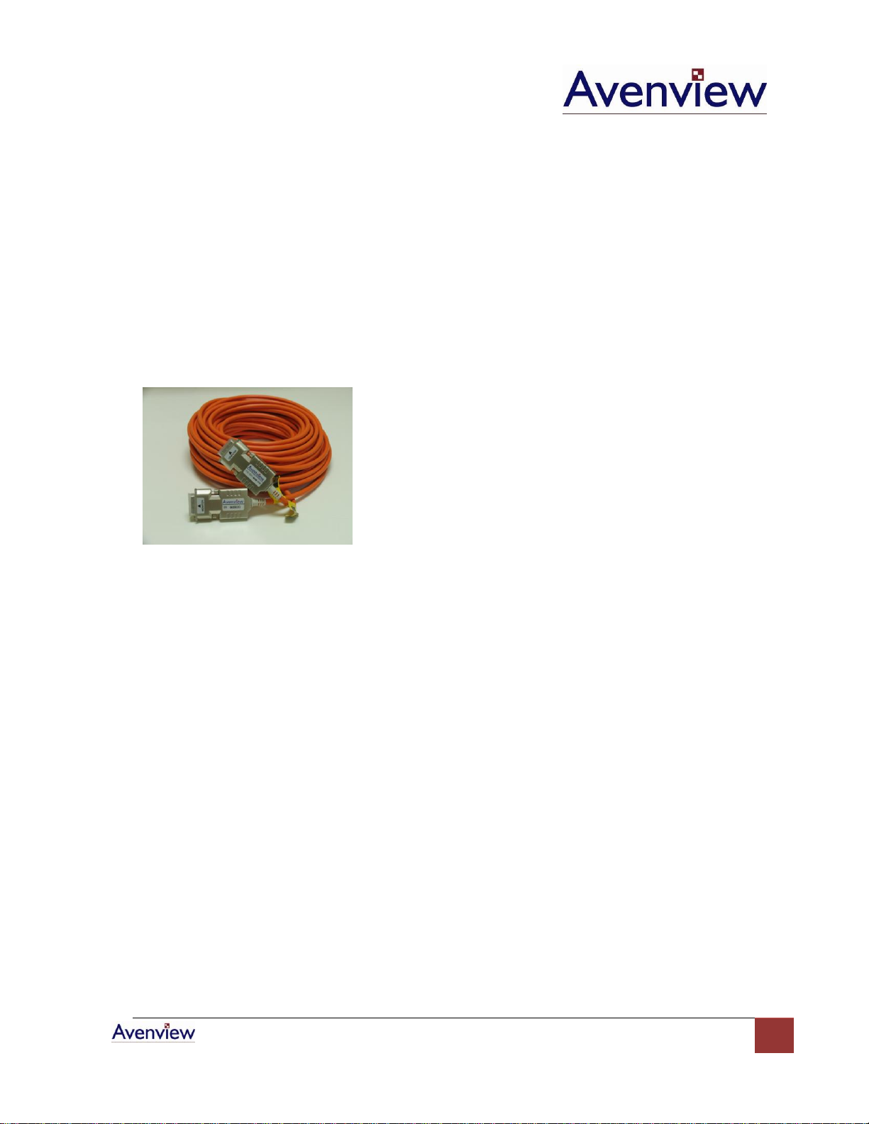
- DVI Optical Cable with Receiver and Transmitter
- User’s Manual
1.7 Before Installation
Put the product in an even and stable location. If the product falls down or drops, it may cause an
injury or malfunction.
Don’t place the product in too high temperature (over 50°C), too low temperature (under 0°C) or high
humidity.
Use the DC power adapter with correct specifications. If inappropriate power supply is used then it
may cause a fire.
Do not twist or pull by force ends of the optical cable. It can cause malfunction.
Page 7
www.avenview.com
7
Use the DC power adapter (optional) with correct specification. The Transmitter which is
connected to a computer uses power from the computer.
Do not twist or pull by force the both ends of the optical cable. It may cause malfunction
1.8 Installation
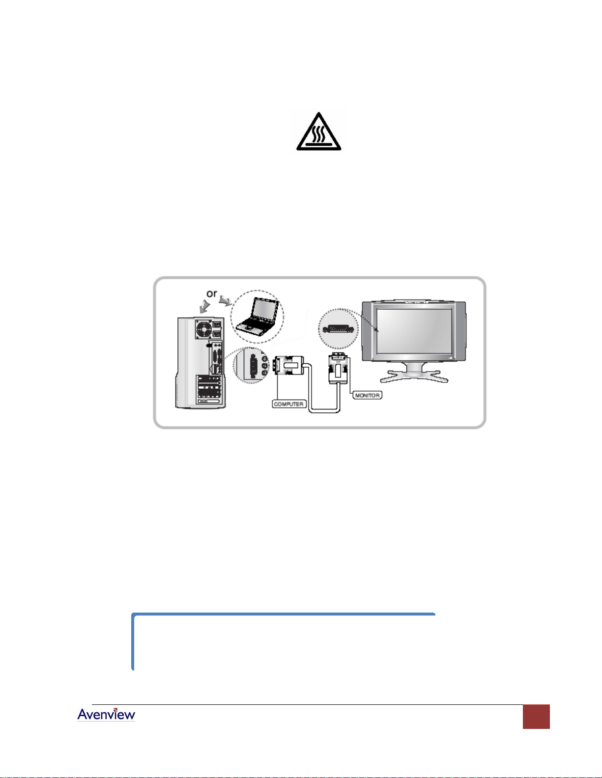
This product is composed of a Transmitter converting the graphic signal of a computer to optical and Optical
Fiber propagating the optical signal and Receiver supplying electrical signal to monitor converted from the
optical signal to electrical signal. The Transmitter should be connected to computer and the Receiver should
be connected to a monitor (as shown below).
Connection diagram of FO-DVI-XX-MM
Avenview FO-DVI-xx-MM is designed to self detect the resolution of the monitor and change the resolution
accordingly. Follow these steps for connecting to a device:
1. Power on your display
2. Connect Transmitter to the PC and Receiver to the Display.
3. Connect the optical fiber between Transmitter and Receiver.
4. Restart the computer.
Page 8
www.avenview.com
8
1.9 General Troubleshooting
Problem
Possible Solution
No Image
Check if the PC Power is on
Check if connection to the computer and the monitor are
correct.
Turn the PC Power off and on again.
Screen Defects Appear
This product supports up to UXGA resolution.
Check the DVI connection
Check the maximum resolution range of the graphics card.
Page 9
www.avenview.com
9
Section 2: Specifications
Item
Description
Video Bandwidth
1.65Gbps (Single Link)
Connector
DVI 24Ping Plug
Power Consumption
5V / 0.5A (min)
Supported Resolution
and Distance
SXGA 1280 x 1024 @ 700 meters (2300 feet)
UXGA 1600 x 1200 @ 500 meters (1650 feet)
WUXGA 1920 x 1200 @ 100 meters (330 feet)
Optical
Optical Source
850nm VCSEL
O/E Converter
PIN Photo Diode
Fiber Type
Multi-Mode Fiber
Environmental
Operation
0˚ to 50˚C Degree
Storage
-20˚ to 70˚C Degree
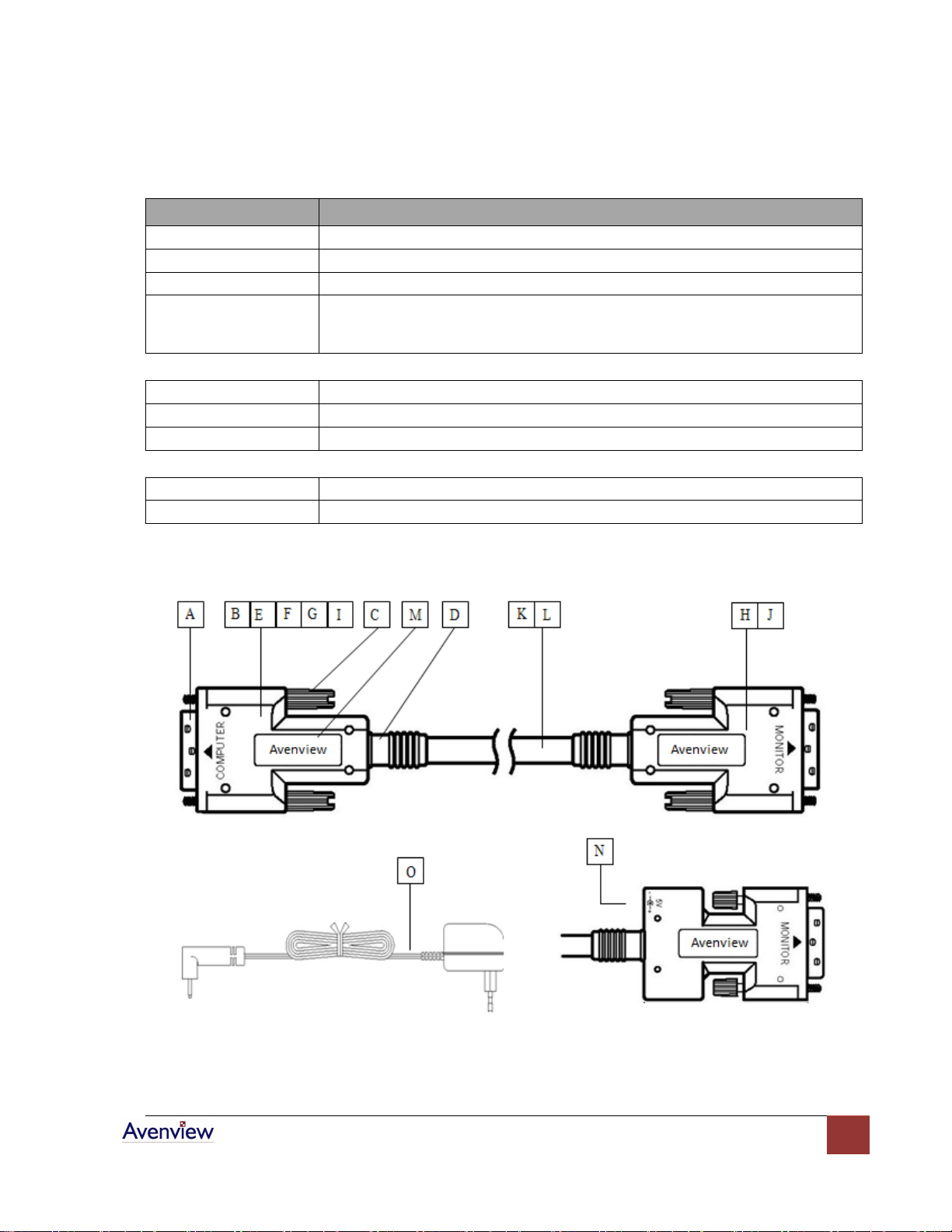
2.1 Part List
Page 10
www.avenview.com
10
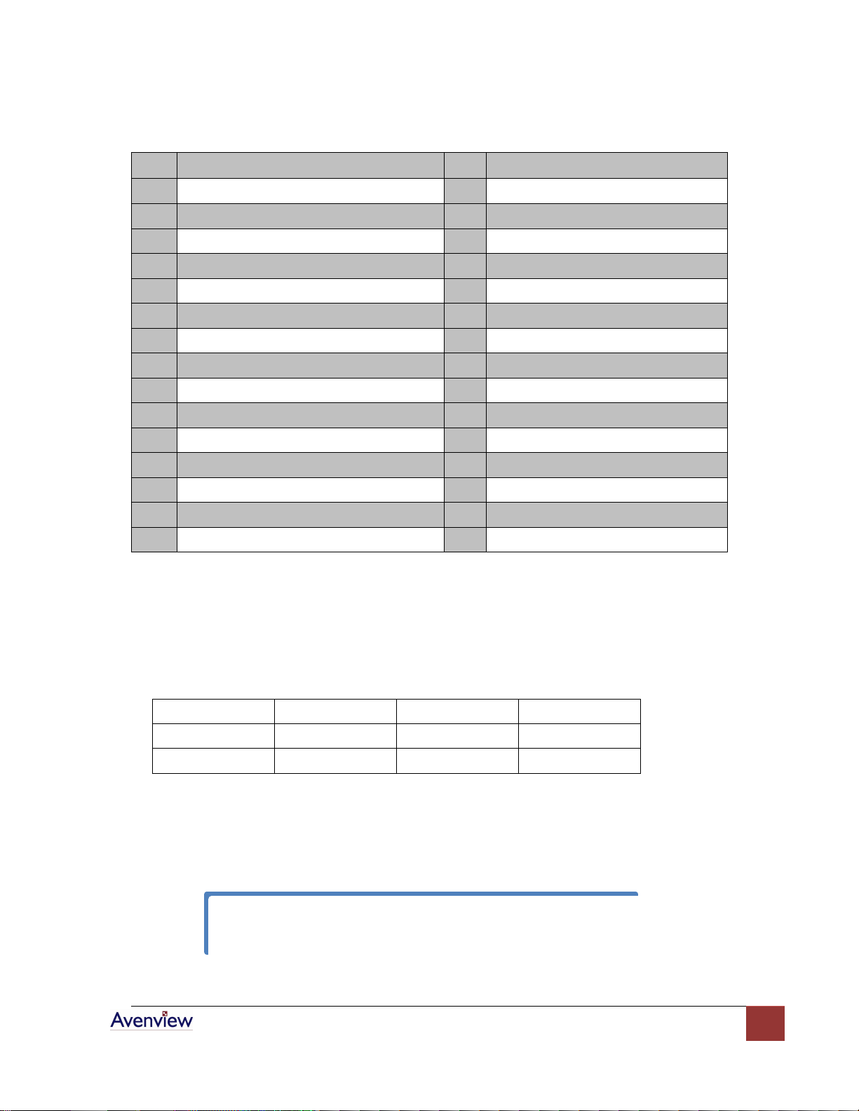
Item Description
Q’ty
Material
A
DVI-D Single Link 18 Plug
2
Glass filled thermoplastic UL94V-0
B
DVI Case-Top, Bottom
2
Glass filled PC UL94V-0
C
DVI Thumb Screw
4
SUM 24L+ABS
D
Stopper
2
PVC 55%
E
Epoxy Printed Circuit Board for Tx
1
FR-4, 1.5t UL94V-0
F
Optical Connector for VCSEL,PD
2
PA46 UL94V-0 + C5210
G
Optical Connector for fiber
2
PA46 UL94V-0
H
Epoxy Printed Circuit Board for Rx
1
FR-4, 1.5t UL94V-0
I
Vertical Surface Emitting Laser Diode
4
GaAs
J
Photo Detector
4
GaAs
K
4 fiber 5 copper DVI Optic Cable
1
See Section 4
L
4 fiber DVI Optic Cable
1
See Section 4
M
Label
4
Polyester-matte 3.3mil
N
DC Power Jack
2
Polyamide 6/6
O
DC Power Adaptor
1
E191362 (UL No)
Item
Typical
maximum
units
Transmitter
0.4 0.53 Watt
Receiver 0.5 0.56 Watt
If graphic board of the computer does not supply over 0.6A, 5V, FO-DVI-XX-MM cable may
not operate normally.
2.2 Power Consumption and DDC Power Requirements
Power consumption of FO-DVI-xx-MM Transmitter and Receiver Module
Transmitter module of FO-DVI-XX-MM without external power supply is operated by drawing out power for
DDC from the computer and receiver module of FO-DVI-XX-MM cable also utilize the DDC power delivered via
copper wire.
Page 11
www.avenview.com
11
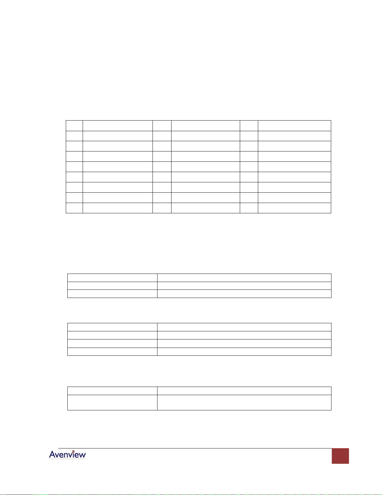
2.3 Signal Pin Assignment
Pin
Signal Assignment
Pin
Signal Assignment
Pin
Signal Assignment
1
T.M.D.S. Data2-
9
T.M.D.S. Data1-
17
T.M.D.S. Data0-
2
T.M.D.S. Data2+
10
T.M.D.S. Data1+
18
T.M.D.S. Data0+
3
T.M.D.S. Data2 Shield
11
T.M.D.S. Data1 Shield
19
T.M.D.S. Data0 Shield
4
No Connect
12
No Connect
20
No Connect
5
No Connect
13
No Connect
21
No Connect
6
DDC Clock
14
+5V Power
22
T.M.D.S. Clock Shield
7
DDC Data
15
Ground (for +5V)
23
T.M.D.S. Clock+
8
No Connect
16
Hot Plug Detect
24
T.M.D.S. Clock-
Housing
Glass Filled Thermoplastic, Black UL94V-0
Contact
Brass
Shell
Steel (Nickel Plated)
Rated
1.5A, 40V (AC)
Contact Resistance
20 m Maximum
Insulation Resistance
1000 m Minimum
Dielectric withstanding Voltage
500VDC
Mating Force
4.5Kg (10lbs) Maximum
Unmating Force
1Kg (2.2lbs) Minimum
4Kg (8.8lbs) Maximum
- Fully compatible with DVI Rev 1.0 standard
- R, G, B and Clock signals are transmitted by optical fibers.
- DDC, Hot plug detection signal and 5V power is transmitted by electrical copper wire.
- External power is not required for operation
2.4 Characteristics of DVI Connector
2.4.1 Material
2.4.2 Electrical
2.4.3 Mechanical
Page 12
www.avenview.com
12
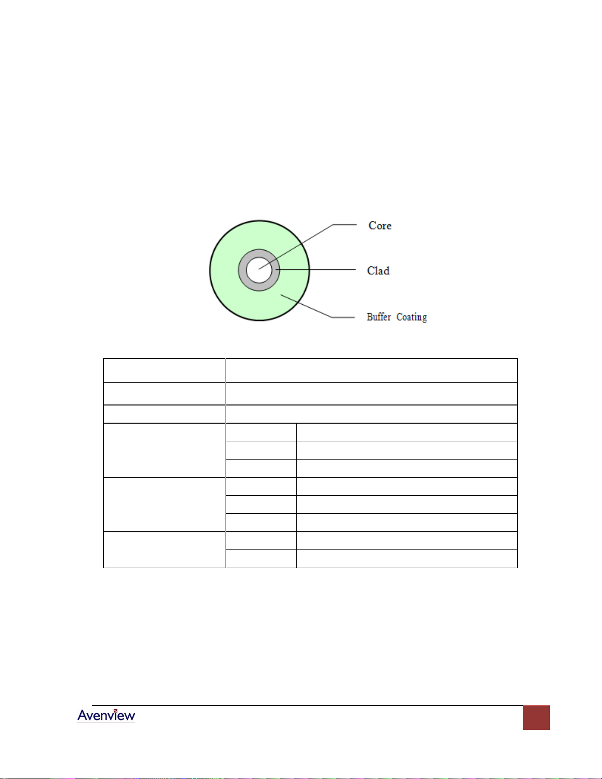
2.5 Characteristics of FO-DVI-XX Cable
Item
Description
Fiber Type
Hard Plastic Clad Silica Optical Fiber(H-PCF)
Index Profile
Semi Graded
Core
Material
GeO2 doped Silica glass
Diameter
200±5um
Non-circularity
Less than 6%
Cladding
Material
Fluoroacrylate
Diameter
225±5um
Concentricity
Less than 6um
Buffer Coating
Material
Acrylate
Diameter
0.5±0.03mm
2.5.1 Optical Fiber Construction and Characteristic
The construction of the buffered optical fiber shall be in accordance with Figure 1 and Table 1
below:
Page 13
www.avenview.com
13
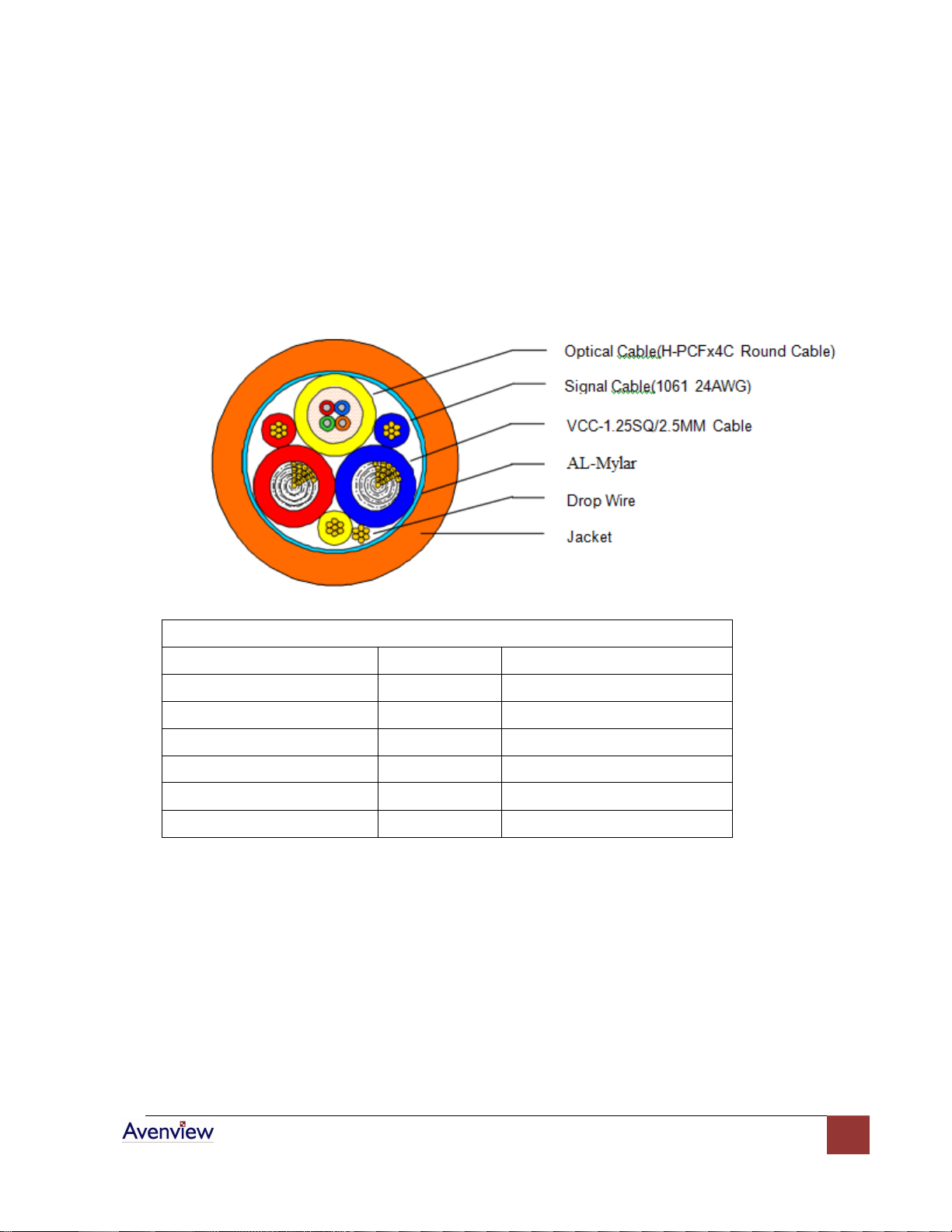
2.6 FO-DVI-XX Cable Construction
The Dimension of FO-DVI-XX-MM Cable
Items
Uni
Specification
DVI Cable Make-up
-
Layer Stranding
Drain Wires (Size/Stranded)
mm(AWG)
-0.203/7 (24)
AL-Mylar Screen Shield
-
A helically
Cable Outer Diameter
mm
7.40±0.20
Jacket Color - FR-PVC(Orange)
Cable Marking - If need
The construction of 4 Optical Fibers and 4 Copper wires cable shall be in accordance with Figure and
Table below:
Page 14

www.avenview.com
14
2.7 Physical Interconnect Specification
Item Test Condition
Requirements
Vibration
ANSI/EIA-364-28, Condition III Method
5A, 15 minute/axis
No discontinuity at 1us or longer (each
contact) when continuity is tested
per ANSI/EIA-364-46
Mechanical Shock
ANSI/EIA-364-27 Condition A
(specified pulse)
No discontinuity at 1us or longer (each
contact) when continuity is tested
per ANSI/EIA-364-46
Durability
ANSI/EIA-364-09
Automatic cycling to 100 cycles
Rate: 10050 cycles per hour
Low Level contact resistance per
ANSI/EIA-364-23
10 m maximum change from
initial per contact pair
Mating &
Un-mating
Forces
ANSI/EIA-364-13
Insert and extract at a speed of
25mm/minute
Un-mating force:
1 kg force minimum,
4 kg force maximum
Mating force:
4.5 kg force maximum
Cable Pullout Force
Test for cable strain relief &
termination integrity. Cable
subjected to 11.3 kg(25.0 lbs) static
load for one minute while
monitoring continuity. Isolate
No discontinuities greater than 1 us
2.7.1 Mechanical Characteristics
Page 15

www.avenview.com
15
2.7.2 Connector Electrical Characteristics
Item
Test Condition
Requirements
Contact Resistance
ANSI/EIA-364-23
20mΩ, maximum, initial per
contact mated pair
10mΩ, maximum change from
original per contact mated pair
Shell Resistance
ANSI/EIA-364-06A-83
Contact resistance measured from
receptacle shell leg to plug cable
braid. Test current = 100mA; Test
Voltage = 5V DC open circuit
maximum
50mΩ, maximum initial
50mΩ, maximum change from
original
Dielectric Withstanding Voltage
ANSI/EIA-364-20
Test voltage 500V DC
V
Method C, unmated and
un-mounted Barometric pressure
of 15 psi
No Flash-over, No Spark-over, No
Excess Leakage, No Breakdown
Insulation Resistance
ANSI/EIA-364-21
Test voltage 500V DC
V
Method C, unmated and
un-mounted
1GΩ minimum between adjacent
contacts and contacts and shell
Contact Current Rating
ANSI/EIA-364-70, TP-70
55°C, maximum ambient
85°C, maximum temperature
change
1.5A minimum
Applied Voltage Rating
40V AC(ms) continuous maximum,
on any signal pin with respect to
the shield
Electrostatic Discharge
IEC 801-2
Test un-mounted from 1kV to 8kV
in 1kV steps using 8mm ball probe
No evidence of discharge to
contacts. Discharge to the shell is
acceptable.
Page 16

www.avenview.com
16
Disclaimer
While every precaution has been taken in the preparation of this document, Avenview Inc. assumes no liability with respect to the
operation or use of Avenview hardware, software or other products and documentation described herein, for any act or omission of
Avenview concerning such products or this documentation, for any interruption of service, loss or interruption of business, loss of
anticipatory profits, or for punitive, incidental or consequential damages in connection with the furnishing, performance, or use of the
Avenview hardware, software, or other products and documentation provided herein.
Avenview Inc. reserves the right to make changes without further notice to a product or system described herein to improve reliability,
function or design. With respect to Avenview products which this document relates, Avenview disclaims all express or implied warranties
Page 17

www.avenview.com
17
regarding such products, including but not limited to, the implied warranties of merchantability, fitness for a particular purpose, and
non-infringement.
 Loading...