

AVENTICS Notice d’instruction: éjecteur à plusieurs étages, série EMS Manuals & Guides [fr]

Betriebsanleitung | Operating instructions | Notice d’instruction |
Istruzioni per l’uso | Instrucciones de servicio | Bruksanvisning
Mehrstufenejektor
Multistage ejector
Éjecteur multi-étages
Eiettore multistadio
Eyector multi etapa
Flerstegsejektor
EMS
R412026279/2017-08, Replaces: –, DE/EN/FR/IT/ES/SV
AVENTICS | EMS | R412026279–BAL–001–AA | Deutsch 1
Deutsch
1 Zu dieser Dokumentation
Diese Anleitung enthält wichtige Informationen, um das
Produkt sicher und sachgerecht zu montieren und in
Betrieb zu nehmen.
O Lesen Sie diese Anleitung vollständig und
insbesondere das Kapitel 2 „Sicherheitshinweise“,
bevor Sie mit dem Produkt arbeiten.
Gültigkeit der Dokumentation
O Diese Dokumentation gilt für Mehrstufenejektoren der
Serie EMS.
Zusätzliche Dokumentationen
O Beachten Sie auch die Anleitungen der übrigen
Anlagenkomponenten.
O Beachten Sie außerdem allgemein gültige, gesetzliche
und sonstige verbindliche Regelungen der
europäischen bzw. nationalen Gesetzgebung sowie die
in Ihrem Land gültigen Vorschriften zur
Unfallverhütung und zum Umweltschutz.
Darstellung von Informationen
Warnhinweise
In
dieser Anleitung stehen Warnhinweise vor einer
Handlungsanweisung, bei der die Gefahr von Personenoder Sachschäden besteht. Die beschriebenen Maßnahmen
zur Gefahrenabwehr müssen eingehalten werden.
Aufbau von Warnhinweisen
SIGNALWORT
Art und Quelle der Gefahr
Folgen bei Nichtbeachtung der Gefahr
O Maßnahmen zur Abwehr der Gefahr
Bedeutung der Signalwörter
GEFAHR
Kennzeichnet eine gefährliche Situation, in der Tod oder
schwere Körperverletzung eintreten werden, wenn sie
nicht vermieden wird.
WARNUNG
Kennzeichnet eine gefährliche Situation, in der Tod oder
schwere Körperverletzung eintreten können, wenn sie
nicht vermieden wird.
VORSICHT
Kennzeichnet eine gefährliche Situation, in der leichte
bis mittelschwere Körperverletzungen eintreten
können, wenn sie nicht vermieden wird.
ACHTUNG
Kennzeichnet Sachschäden: Das Produkt oder die
Umgebung können beschädigt werden.
Symbole
Wenn diese Information nicht beachtet wird, kann
das zu Verschlechterungen im Betriebsablauf
führen.
2 Sicherheitshinweise
Das Produkt wurde gemäß den allgemein anerkannten
Regeln der Technik hergestellt. Trotzdem besteht die
Gefahr von Personen- und Sachschäden, wenn Sie die
folgenden grundsätzlichen Sicherheitshinweise und die
Warnhinweise vor Handlungsanweisungen in dieser
Anleitung nicht beachten.
O Lesen Sie diese Anleitung gründlich und vollständig,
bevor Sie mit dem Produkt arbeiten.
O Bewahren Sie die Anleitung so auf, dass sie jederzeit
für alle Benutzer zugänglich ist.
O Geben Sie das Produkt an Dritte stets zusammen mit
der Betriebsanleitung weiter.
Bestimmungsgemäße Verwendung
W Der Ejektor dient zur Vakuumerzeugung um in
Verbindung mit Sauggreifern Objekte mittels Vakuum
zu greifen und dann zu transportieren.
W Als zu evakuierendes Medium sind neutrale Gase
gemäß ISO 8573-1 zugelassen. Neutrale Gase sind
Luft, Stickstoff und Edelgase (z. B. Argon, Helium,
Neon). Nicht zugelassen sind aggressive Gase oder
Medien wie z. B. Säuren, Säuredämpfe, Laugen,
Biozide, Desinfektionsmittel und Reinigungsmittel.
W Das Gerät dient nicht zum Transport (Durchsaugen)
von Flüssigkeiten, nicht neutralen Gasen und/oder
Granulaten.
W Schalldämpfer darf nicht verschlossen sein.
W Andernfalls ist Beschädigung des Ejektors und sogar
Verletzungsgefahr nicht auszuschließen.
W Die Ejektoren dürfen nur mit einem maximalen Druck
von 6,0 bar betrieben werden.
W Montage, Inbetriebnahme, Wartung nur durch
Fachkräfte.
W Bedienen durch vom Betreiber unterwiesenes
Bedienpersonal.
W Personen die aufgrund einer physischen, psychischen
oder sensorischen Einschränkung nicht in der Lage
sind die Maschine gefahrlos zu bedienen, dürfen die
Maschine nicht oder nur unter Aufsicht einer
verantwortlichen Person bedienen.
Die bestimmungsgemäße Verwendung schließt auch ein,
dass Sie diese Anleitung und insbesondere das Kapitel 2
„Sicherheitshinweise“
haben.
vollständig gelesen und verstanden

1
3
1
AVENTICS | EMS | R412026279–BAL–001–AA | Deutsch 2
Nicht bestimmungsgemäße Verwendung
Als nicht bestimmungsgemäße Verwendung gilt, wenn Sie
den Ejektor
O außerhalb der Anwendungsgebiete verwenden, die in
dieser Anleitung genannt werden,
O unter Betriebsbedingungen verwenden, die von den in
dieser Anleitung beschriebenen abweichen,
Qualifikation des Personals
Die Montage, Inbetriebnahme, Demontage und
Instandhaltung (inkl. Wartung und Pflege) erfordern
grundlegende mechanische und pneumatische
Kenntnisse sowie Kenntnisse der zugehörigen
Fachbegriffe.
Um die Betriebssicherheit zu gewährleisten, dürfen diese
Tätigkeiten daher nur von einer entsprechenden Fachkra ft
oder einer unterwiesenen Person unter Leitung einer
Fachkraft durchgeführt werden.
Eine Fachkraft ist, wer aufgrund seiner fachlichen
Ausbildung, seiner Kenntnisse und Erfahrungen, sowie
seiner Kenntnisse der einschlägigen Bestimmungen, die
ihm übertragenen Arbeiten beurteilen, mögliche Gefahren
erkennen und geeignete Sicherheitsmaßnahmen treffen
kann. Eine Fachkraft muss die einschlägigen
fachspezifischen Regeln einhalten.
Allgemeine Sicherheitshinweise
W Die Betriebsanleitung enthält wichtige Informationen
zum Umgang mit dem System. Betriebsanleitung
sorgfältig durchlesen und für spätere Zwecke
aufbewahren!
W Der Anschluss und die Inbetriebnahme des Systems
darf erst erfolgen, nachdem die Betriebsanleitung
gelesen und verstanden wurde!
W Arbeiten am System dürfen nur von qualifiziertem
Fachpersonal durchgeführt werden.
W Nur die vorgesehenen Anschlussmöglichkeiten,
Befestigungsbohrungen und Befestigungsmittel
verwenden.
W Wartung nur bei demontiertem Druckluftanschluss
W Allgemeine Sicherheitsvorschriften, EN-Normen und
VDE-Richtlinien müssen beachtet und eingehalten
werden!
W Bei der Handhabung von gefährlichen Stoffen sind die
für diese Stoffe gültigen Sicherheitshinweise zu
beachten.
Produkt- und technologieabhängige
Sicherheitshinweise
W Das Produkt wird in Verbindung mit einem
automatisierten Handlingsystem (Portal/Roboter)
eingesetzt.
W Deshalb gelten außerdem die Sicherheitsvorschriften
des entsprechenden Systems!
W Unter Druckluft stehende Geräte können Personen-
und Sachschäden verursachen.
W Abluft und eventuell angesaugte Medien und Teile
treten mit hoher Geschwindigkeit aus dem
Abluftanschluss aus.
W Verletzungsgefahr – vor allem im Augenbereich! Nicht
in den Luftstrom treten oder schauen.
W Anschlüsse unbedingt richtig anschließen und niemals
verschließen – Berstgefahr!
W Vakuum überwachen, um Störungen der
Vakuumerzeugung zu erkennen.
W Das Produkt darf nicht in aggressiver Umgebungsluft
(z. B. Lösungsmitteldämpfe) betrieben werden!
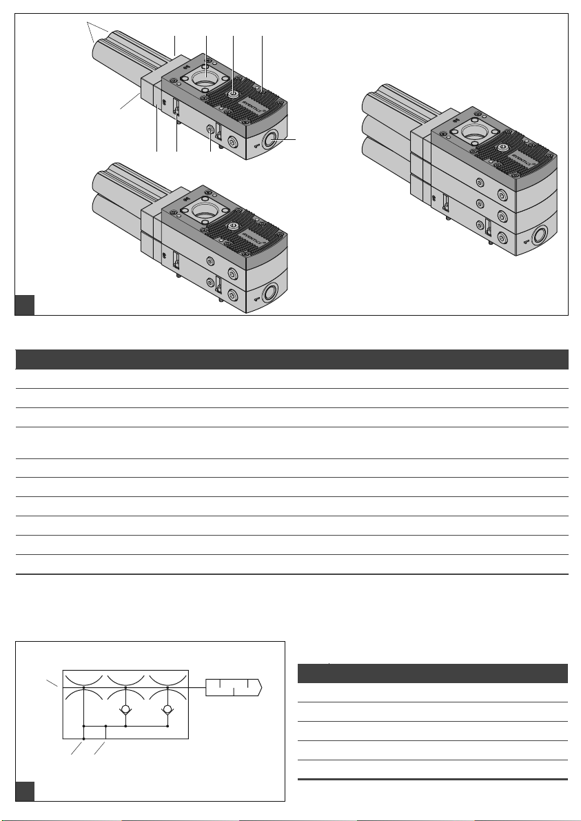
3Lieferumfang
Im Lieferumfang sind enthalten:
W 1 Mehrstufenejektor gemäß Bestellung
(Typen s. Abb. , Technische Daten)
W Betriebsanleitung
W Befestigungsschrauben
4 Montage und Betrieb
WARNUNG
Ejektormodul kann aus der Bohrung geschleudert
werden, wenn es unzureichend fixiert ist
Schwerer Personenschaden
O Ejektormodul fixieren
O Schutzbrille tragen
VORSICHT
Verletzungsgefahr durch Montage unter Druck oder
Spannung!
Die Montage unter Druck oder anliegender elektrischer
Spannung kann zu Verletzungen führen und das
Produkt oder Anlagenteile beschädigen.
O Schalten Sie den relevanten Anlagenteil drucklos
und spannungsfrei, bevor Sie das Produkt
montieren.
O Sichern Sie die Anlage gegen Wiedereinschalten.
Ejektormodul befestigen
Der Schalldämpfer fixiert das Ejektormodul.
Deshalb darf der Ejektor nicht ohne Schalldämpfer
betrieben werden.
Ausnahme: Wenn der Ejektor ohne Schalldämpfer
betrieben werden soll, muss das Ejektormodul über die
Schalldämpfer-Aufnahme und die beiden mitgelieferten
Schrauben M 4x16 (2 Nm) gesichert werden (v gl. Abschnitt
„Aufbau“ ).

2
1
AVENTICS | EMS | R412026279–BAL–001–AA | Deutsch 3
VORSICHT
Betrieb ohne Schalldämpfer
Ejektor emittiert Schall
O Gehörschutz tragen
VORSICHT
Angesaugte Partikel mit hoher Geschwindigkeit
Augenschäden
O Schutzbrille tragen
VORSICHT
Durch Druckluft/Vakuum können geschlossene Geräte
explodieren/implodieren
Personen- und/oder Sachschäden
O Schutzbrille tragen
O Schalldämpfer darf nicht verschlossen sein
O Befestigen Sie den Ejektor mit den mitgelieferten M5-
Schrauben (4x). Anzugsmoment max. 5 Nm!
Alternativ kann ein Befestigungswinkel verwendet
werden, vgl. Kapitel 6 „Zubehör“.
Anschluss
W Verwenden Sie die empfohlenen
Schlauchdurchmesser.
W Ein zu klein gewählter Innendurchmesser
druckluftseitig bewirkt, dass dem Gerät nicht
genügend Druckluft für die optimale Leistung
zugeführt wird.
W Ein zu klein gewählter Innendurchmesser
vakuumseitig bewirkt einen zu hohen
Strömungswiderstand entlang der Schlauchwandung,
was sich negativ auf die Saugleistung und damit auf
die Ansaugzeiten auswirkt. Allerdings sollten die
Schlauchdurchmesser nicht beliebig groß gewählt
werden um bedingt durch das vergrößerte Volumen,
die Ansaugzeiten nicht zu verlängern.
W Schlauchleitungen sollten möglichst kurz verlegt
werden, um die Reaktionszeiten möglichst klein zu
halten. Schlauchleitungen knick- und quetschfrei
verlegen.
Nach dem Herstellen aller pneumatischen Verbindungen
kann das Gerät mit Druckluft beaufschlagt werden.
Weitere Angaben
Für sichere Installation und störungsfreien Betrieb sind
weiterhin folgende Verhaltensweisen nebeneinander zu
beachten und einzuhalten:
W Prüfen Sie das Produkt auf offensichtliche Mängel, wie
beispielsweise Risse im Gehäuse oder fehlende
Schrauben, Abdeckkappen, Dichtungen!
W Elektrische Leitungsverbindungen, Pneumatik- und
Vakuumschläuche müssen dauerhaft mit dem Produkt
verbunden und gesichert sein!
W Produkt spannungs- und druckfrei schalten und gegen
unbefugtes Wiedereinschalten sichern!
W Der Betrieb in explosionsgefährdeter Umgebung ist
nicht zulässig. Brand- und Explosionsgefahr!
W Eigenmächtige Umbauten und Veränderungen des
Produktes und seinen Bauteilen sind aus
Sicherheitsgründen verboten!
Ausnahme: Ein Upgrade des Ejektors auf eine höhere
Leistungsklasse ist mithilfe eines Upgrade-Sets auf
Anfrage möglich.
W Im Betrieb ausreichend Sicherheitsabstand einhalten,
Quetschgefahr durch sich bewegende Teile!
W Das Produkt ist mit geeigneten Schutzvorrichtungen
zu betreiben. Vor unbefugtem Zutritt absichern!
W Der Betrieb außerhalb der spezifizierten
Leistungsgrenzen ist nicht zulässig.
Bei fehlerhafter Montage, Betrieb außerhalb der
Leistungsgrenzen und eigenmächtigen Umbauten
bzw. Veränderungen des Produkts erlischt die
Gewährleistung!
Die Einbaulage des Ejektors ist beliebig.
5 Instandhaltung und
Instandsetzung
Wartung
Der Ejektor kann zu Wartungs- und Reinigungszwecken
geöffnet werden. Bei erneutem Zusammenbau sind die
vorgegebenen Anzugsmomente der Schrauben
einzuhalten (vgl. Abschnitt „Aufbau“ ).
Ersatz- und Verschleißteile
Bezeichnung Materialnummer
Schalldämpfer R412026280
Dichtrahmen R412026281
O-Ring R412026282

AVENTICS | EMS | R412026279–BAL–001–AA | Deutsch 4
L5
L4
B4
B3
B2
B1
LG5
G2
G3
G4
B
L2
L
X1L2
L1
L3
H1
H
G1
Y1
3
2
1
6Zubehör
Bezeichnung Typ Materialnummer
Verschlussstopfen R412026139
Befestigungswinkel (inkl.
Schrauben)
Düsenpatrone SEP-HF R412026137
SEP-HV R412026138
Weiteres Zubehör entnehmen Sie bitte dem Online-Katalog unter
www.aventics.com/pneumatics-catalog
R412026103
7Technische Daten
Max. Vakuum [%] Typ HF = 60
Opt. Betriebsdruck [bar] 4 ... 5
Betriebsdruck [bar] 2 ... 6
Einbaulage beliebig
Temperaturbereich [°C] 0...+60
Betriebsmedium
druckluftseitig
Betriebsmedium
vakuumseitig
Typ Evakuie-
EMS-25-HF 60 290 80
EMS-25-HV 90 300 105
EMS-50-HF 60 500 160
EMS-50-HV 90 510 210
EMS-75-HF 60 710 230
EMS-75-HV 90 720 305
EMS-100-HF 60 860 300
EMS-100-HV 90 870 395
EMS-125-HF 60 1010 370
EMS-125-HV 90 1010 470
EMS-150-HF 60 1120 435
EMS-150-HV 90 1140 545
1)
Bei optimalem Betriebsdruck
rungsgrad
[%] [l/min] [l/min]
Typ HV = 90
N
eutrale Gase gemäß EN 983
z. B. Luft, Stickstoff und
Edelgase (z. B. Argon, Helium,
Neon), gefiltert 40 μm, geölt
oder ungeölt,
Druckluftqualität Klasse 3-3-3
nach ISO 8573-1
trockene und nicht
aggressive Gase
mögen
Luftver-
brauch
Max. Saugver-
Typ Schallpegel Druck-
frei
angesaugt
[dB]
EMS-25-HF 61 54 2,0 … 6,0 0,8
EMS-25-HV 65 55 2,0 … 6,0 0,8
EMS-50-HF 65 55 2,0 … 6,0 0,8
EMS-50-HV 66 59 2,0 … 6,0 0,8
EMS-75-HF 67 57 2,0 … 6,0 1,1
EMS-75-HV 68 62 2,0 … 6,0 1,1
EMS-100-HF 69 58 2,0 … 6,0 1,1
EMS-100-HV 70 64 2,0 … 6,0 1,1
EMS-125-HF 70 60 2,0 … 6,0 1,5
EMS-125-HV 72 65 2,0 … 6,0 1,5
EMS-150-HF 71 61 2,0 … 6,0 1,5
EMS-150-HV 73 66 2,0 … 6,0 1,5
bereich
[dB]
Gewicht
[bar] [kg]
Verwendete Materialien
Bauteil Material
Grundkörper und
Anschlussplatte
Deckel Glasfaserverstärkter
Innenteile Aluminiumlegierung,
Dichtungen NBR
1)
Schrauben Stahl verzinkt; Edelstahl
Befestigungsblech Stahl verzinkt
Glasfaserverstärkter
Kunststoff
Kunststoff
Messing, NBR
Typ / Type / Tipo
EMS 125/150
1
675
9 / 10
44 89 / 10
3
1
Typ / Type / Tipo
EMS 25/50
Typ / Type / Tipo
EMS 75/100
1
1
24 / 5
3
2
1
3
1
Aufbau
Pos Bezeichnung
1 Druckluftanschluss, max. 15 Nm
2 Vakuumanschluss, max. 25 Nm
3 Abluftöffnungen
4 Abblasanschluss/Belüftungsanschluss, max.15 Nm
Externes Abblasen mit Abblasventil 2/2-NC* (vakuumdicht)
5 Vakuumabfrage, max. 10 Nm
6 Befestigungsschrauben M5 (4x), max. 5 Nm
7 Schalldämpfer-Aufnahme
8 Befestigungsschrauben M4 (8x für Gehäusedeckel) max. 2,5 Nm
9 Befestigungsschrauben M4x16 (2x für Schalldämpferaufnahme) max. 2 Nm
10 Befestigungsschrauben M4x35 (2x für Schalldämpfer) max. 2 Nm
* Weiteres Zubehör entnehmen Sie bitte dem Online-Katalog unter www.aventics.com/pneumatics-catalog
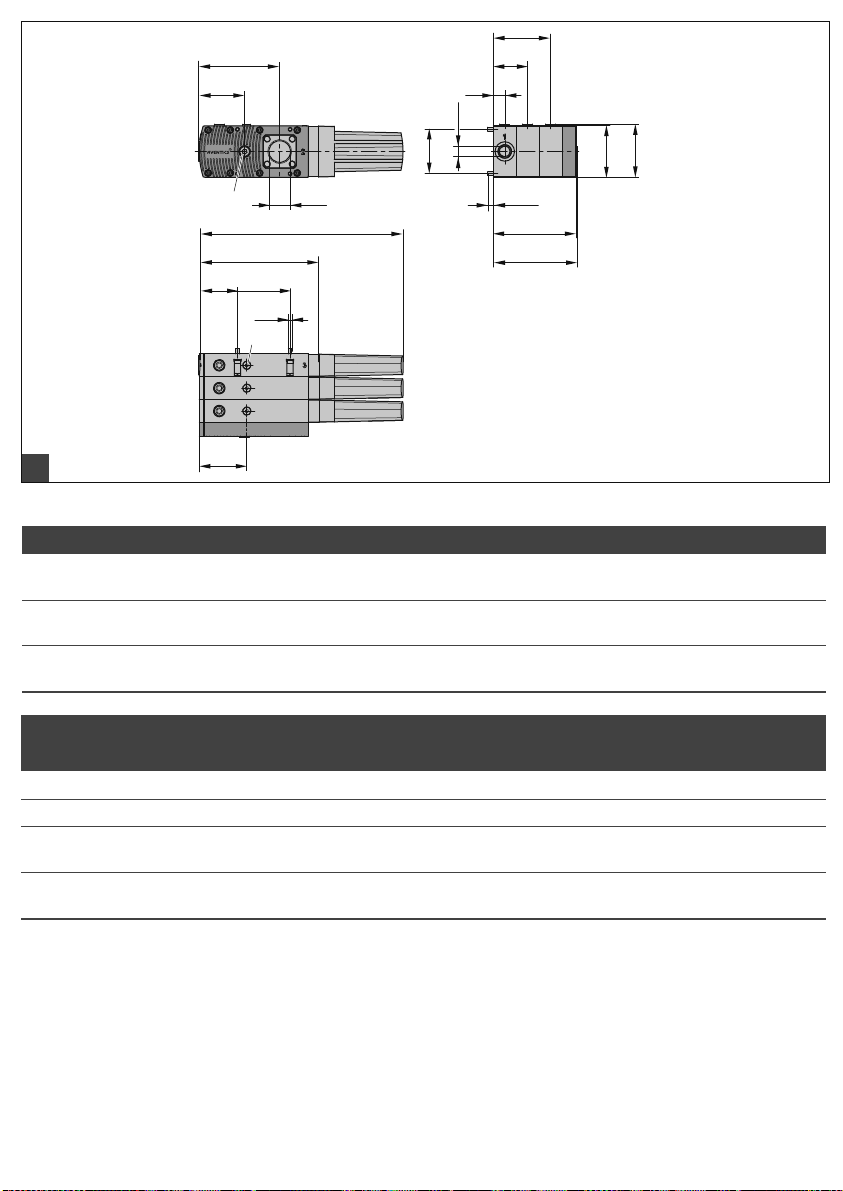
Pneumatischer Anschluss
Pos Bezeichnung
1 Druckluftanschluss
2 Vakuumanschluss
3 Abluft
4 Abblasen/Belüftung
5 Vakuumabfrage

L5
L4
B4
B3
B2
B1
LG5
G2
G3
G4
B
L2
L
X1L2
L1
L3
H1
H
G1
Y1
3
2
1
Abmessungen und Anschlüsse
Typ L L1 L2 L3 L4 L5 B B1 B2 B3 B4 H H1 X1 Y1
EMS-25-HF/HV
EMS-50-HF/HV
EMS-75-HF/HV
EMS 100-HF/HV
EMS-125-HF/HV
EMS-150-HF/HV
168285546711364515316 – –72747462
168 285 54 67 113 64 83 85 16 48 – 72 74 74 62
168 285 54 67 113 64 115 117 16 48 80 72 74 74 62
Typ G1 G2 G3 G4 G5 Lg5 empf. Schlauchinnen - Ø*
EMS-25-HF/HV G3/8"-IG G3/4"-IG G1/4"-IG G1/8"-IG M5-AG 8,5 6 20
EMS-50-HF/HV G3/8"-IG G3/4"-IG G1/4"-IG G1/8"-IG M5-AG 8,5 6 25
EMS-75-HF/HV
EMS-100-HF/HV
EMS-125-HF/HV
EMS-150-HF/HV
* Bei Schlauchlängen bis 2 m
G3/8"-IG G1"-IG G1/4"-IG G1/8"-IG M5-AG 8,5 9 32
G3/8"-IG G1"-IG G1/4"-IG G1/8"-IG M5-AG 8,5 11 32
Druckluft Vakuum

AVENTICS | EMS | R412026279–BAL–001–AA | Deutsch 5

AVENTICS | EMS | R412026279–BAL–001–AA | English 6
English
1 About this Documentation
These instructions contain important information for the
safe and appropriate assembly and commissioning of the
product.
O Read these instructions carefully, especially chapter 2
“Notes on Safety”, before you start working with the
product.
Documentation validity
O This documentation is valid for EMS series multistage
ejector.
Additional documentation
O Also follow the instructions for the other system
components.
O Please also observe the generally relevant, statutory
and other binding regulations of European and national
legislation and the national regulations for accident
prevention and environmental protection in your
country.
Presentation of information
Warnings
In this document, there are safety instructions before the
steps whenever there is a danger of personal injury or
damage to the equipment. The measures described to
avoid these hazards must be followed.
Structure of warnings
SIGNAL WORD
Hazard type and source
Consequences of non-observance
O Measures to avoid these hazards
Meaning of the signal words
DANGER
Indicates a hazardous situation which, if not avoided,
will certainly result in death or serious injury.
WARNING
Indicates a hazardous situation which, if not avoided,
could result in death or serious injury.
CAUTION
Indicates a hazardous situation which, if not avoided,
could result in minor or moderate injuries.
NOTICE
Indicates that damage may be inflicted on the product or
the environment.
Symbols
Operation may be impaired if this information is
disregarded.
2 Notes on Safety
The product has been manufactured according to the
accepted rules of current technology. Even so, there is a
risk of injury or damage if the following general safety
instructions and the specific warnings given in this
instruction manual are not observed.
O Please read all these instructions carefully before
working with the product.
O Keep these instructions in a location where they are
accessible to all users at all times.
O Always include the operating instructions when you
pass the product on to third parties.
Intended use
W The ejector is designed to generate a vacuum for
gripping and transporting objects when used in
conjunction with suction pads.
W Neutral gases in accordance with ISO8573-1 are
approved as evacuation media. Neutral gases include
air, nitrogen and inert gases (e.g. argon, helium and
neon). Aggressive gases or media such as acids, acid
fumes, bases, biocides, disinfectants or detergents are
not permitted.
W The device is not suitable for transporting (through-
suction) of liquids, non neutral gases and/or
granulates.
W Silencer must not be closed. Otherwise damages of the
ejector and even injury risks can not be excluded.
W The ejectors may only be operated with a maximum
pressure of 6,0 bar.
W Assembly, commissioning, maintenance must only be
carried out by qualified persons.
W Operating only by persons that are trained by the
operator.
W Persons that are not in a position to operate the
machine safely due to physical, mental or sensory
limitations, may only operate the machine under
supervision of a responsible person.
Intended use includes having read and understood these
instructions, especially chapter 2 “Notes on Safety”.

1
3
1
AVENTICS | EMS | R412026279–BAL–001–AA | English 7
Improper use
It is considered improper use when the ejector
O is used for any application not stated in these
instructions, or
O if they are used under operating conditions that deviate
from those described in these instructions.
Personnel qualifications
Assembly, disassembly, commissioning, and maintenance
(incl. service and care) require basic mechanical and
pneumatic knowledge, as well as knowledge of the
appropriate technical terms.
To ensure safe operation, this work may only be
performed by qualified personnel or trained persons
working under the supervision of qualified personnel.
A qualified employee is defined as an employee who has
received technical training and has the knowledge and
experience - including knowledge of corresponding
regulations - necessary to enable him or her to recognize
possible dangers and implement the appropriate safety
measures while performing tasks. Qualified personnel
must observe the pertinent industry-specific rules and
regulations.
General safety instructions
W The operating instructions contains important
information about the use of the system. Read the
operating instructions carefully and keep it for future
reference!
W The installation and commissioning of the system
should not be made until you have read and
understood the operating instructions fully!
W Work on the system may only be carried out by
qualified specialist personnel.
W Use only the connection facilities, mounting holes and
mounting components provided for this purpose.
W Maintenance only when compressed air is
disconnected
W General safety regulations, European standards and
VDE guidelines must be observed and complied with.
W You must observe the applicable safety instructions
when handling hazardous materials.
Safety instructions related to the product
and technology
W The product is used with an automated handling
system (portal/robot).
W For this reason, you must also follow the safety
regulations of the corresponding system.
W Devices with compressed air can cause harm to people
and damage property.
W The exhaust air and any particles which may have been
drawn into the ejector leave the exhaust-air outlet at
high velocities. This may cause injuries, particularly to
the eyes. Never stand in the stream of exhaust air and
never look into the exhaust-air outlet when the ejector
is connected to the compressed-air supply!
W Ensure that you make all connections correctly and
never close them off – danger of bursting!
W The vacuum created should be monitored to detect
possible faults in vacuum generation.
W Do not operate the product in aggressive environments
(e.g. ambient air containing solvent fumes).
3 Delivery Contents
The delivery contents include:
W Multistage ejector as per order
(for types, see figure , technical data)
W Operating instructions
W Mounting screws
4 Assembly and Operation
WARNING
The ejector module may be flung out of the hole if it is
not adequately secured
Serious personal injury
O Attach the ejector module securely
O Wear protective glasses
CAUTION
Danger of injury if assembled under pressure
or voltage
Assembling when under pressure or electrical voltage
can lead to injuries and damage to the product or
system components.
O Make sure that the relevant system part is not under
voltage or pressure before you assemble the
product.
O Protect the system against being switched on.
Mounting ejector module
The silencer fixes the ejector module.
Therefore the ejector may not be operated without
silencer.
Exception: If the ejector is to be operated without silencer,
the ejector module must be secured with the silencer
adapter and the two supplied screws M4x16 (2 Nm)
(see section “Construction” ).
2
1
AVENTICS | EMS | R412026279–BAL–001–AA | English 8
CAUTION
Operation without silencer
Ejector emits sound
O Wear ear protection
CAUTION
Picked up particles move at high speeds
Eye injuries
O Wear protection glasses
CAUTION
Pressure/Vacuum can cause closed devices to
explode/implode
Personal injury and/or damage to property
O Wear protection glasses
O Silencer must not be closed
O Secure the ejector using the secured screws (M5).
Maximum torque 5 Nm!
As an alternative a mounting bracket can be used,
see chapter 6 “Accessories”.
Connection
W Use hoses of the recommended diameters.
W A hose with insufficient internal diameter on the
pressure side will prevent the unit from receiving the
amount of compressed air necessary for optimum
performance.
W A hose with insufficient internal diameter on the
vacuum side will cause excessive flow resistance
along the wall of the hose, with negative effects on the
suction capacity and thus on the evacuation times. On
the other hand, a hose whose internal diameter is too
large will have a large internal volume and will thus
also result in longer evacuation times.
W Hoses should be kept as short as possible in order to
reduce the reaction times to a minimum.
W Take care that the hoses are not kinked or pinched.
After all pneumatic connections have been made, the
compressed-air supply can be turned on.
W Make sure that the product is disconnected,
depressurized and cannot be switched on again
without authorization.
W The system may not be operated in environments
where there is a risk of explosion. Risk of fire and For
safety reasons, modifications or changes may not be
made to the product or its components without
approval.
Exception: On request, it is possible to upgrade the
ejector to a higher performance class using an
upgrade set.
W Maintain a safe distance during operation: The moving
parts present a risk of crushing injuries.
W The product must be operated with suitable safety
equipment. Protect the product from unauthorized
access.
W The device may not be operated outside its specified
capacities and limits.
The warranty is void in case of faulty installation,
operation outside the performance limits and
unauthorized changes or modifications to the
product.
The installation position of the ejector is any.
5 Service and Repairs
Maintenance
The ejector can be opened for maintenance and cleaning
purposes.
During assembly, the prescribed tightening torque of the
screws must be observed (see section “Construction” ).
Spare and wearing parts
Designation Mat. no.
Silencer R412026280
Sealing frame R412026281
O-ring R412026282
More information
For safe installation and trouble-free operation, the
following instructions must be observed and complied
with:
W Check the product for apparent damage, such as
fissures in the housing or missing screws, cover caps
or seals.
W Electrical line connections, and pne umatic and vacuum
tubes, must be permanently connected to the product
and secured.

AVENTICS | EMS | R412026279–BAL–001–AA | English 9
6 Accessories
Designation Type Mat. no.
Sealing plug R412026139
Mounting bracket
(incl. screws)
Nozzle cartridge SEP-HF R412026137
SEP-HV R412026138
Further accessories can be found in our online catalog at
www.aventics.com/pneumatics-catalog.
R412026103
7Technical Data
Max. vacuum [%] Type HF = 60
Opt. operating
pressure [bar]
Operating pressure [bar] 2 ... 6
Installation position any
Temperature range [°C] 0...+60
Operating medium on
pressure side
Operating medium
on vacuum side
Type Degree of
EMS-25-HF 60 290 80
EMS-25-HV 90 300 105
EMS-50-HF 60 500 160
EMS-50-HV 90 510 210
EMS-75-HF 60 710 230
EMS-75-HV 90 720 305
EMS-100-HF 60 860 300
EMS-100-HV 90 870 395
EMS-125-HF 60 1010 370
EMS-125-HV 90 1010 470
EMS-150-HF 60 1120 435
EMS-150-HV 90 1140 545
1)
At opt. operating pressure
evacuation
[%] [l/min] [l/min]
Type HV = 90
4 ... 5
Neutral gases in accordance
with EN 983, e.g. air, nitrogen
and inert gases (e.g. argon,
helium, neon), filtered to
40 μm, oiled or oil-free,
compressed air quality class
3-3-3 as per ISO 8573-1
dry, non-aggressive gas
Max. suction
capacity
consumption
Type Noise level Compr.
free
load gripped
[dB]
EMS-25-HF 61 54 2.0 … 6.0 0.8
EMS-25-HV 65 55 2.0 … 6.0 0.8
EMS-50-HF 65 55 2.0 … 6.0 0.8
EMS-50-HV 66 59 2.0 … 6.0 0.8
EMS-75-HF 67 57 2.0 … 6.0 1.1
EMS-75-HV 68 62 2.0 … 6.0 1.1
EMS-100-HF 69 58 2.0 … 6.0 1.1
EMS-100-HV 70 64 2.0 … 6.0 1.1
EMS-125-HF 70 60 2.0 … 6.0 1.5
EMS-125-HV 72 65 2.0 … 6.0 1.5
EMS-150-HF 71 61 2.0 … 6.0 1.5
EMS-150-HV 73 66 2.0 … 6.0 1.5
air range
[dB]
Materials used
Part Material
Body and connection
plate
Cover Fiberglass reinforced plastic
Internal parts Aluminium alloy, Brass, NBR
Gaskets NBR
Screws Galvanized steel; stainless
Air
1)
Mounting plate Galvanized steel
Fiberglass reinforced plastic
steel
Weight
[bar] [kg]

1
3
1
Construction
Typ / Type / Tipo
EMS 125/150
1
675
9 / 10
44 89 / 10
3
1
Typ / Type / Tipo
EMS 25/50
Typ / Type / Tipo
EMS 75/100
1
1
24 / 5
3
2
Pos Designation
1 Compressed air connection, max. 15 Nm
2 Vacuum connection, max. 25 Nm
3 Exhaust vents
4 Blow-off connection/Ventilation connection, max.15 Nm
External Blow-Off with Blow-Off valve 2/2-NC* (vacuum-tight)
5 Vacuum control, max. 10 Nm
6 Mounting screws M5 (4x), max. 5 Nm
7 Silencer adapter
8 Mounting screws M4 (8x for cover) max. 2.5 Nm
9 Mounting screws M4x16 (2x for Silencer adapter) max. 2 Nm
10 Mounting screws M4x35 (2x for Silencer) max. 2 Nm
* Further accessories can be found in our online catalog at www.aventics.com/pneumatics-catalog.
Pneumatic Connections
Pos Designation
1 Compressed air connection
2 Vacuum connection
3 Exhaust
4 Blow-off/Ventilation
5 Vacuum control
2
1
Dimensions and connections
L5
L4
B4
B3
B2
B1
LG5
G2
G3
G4
B
L2
L
X1L2
L1
L3
H1
H
G1
Y1
3
Type L L1 L2 L3 L4 L5 B B1 B2 B3 B4 H H1 X1 Y1
EMS-25-HF/HV
EMS-50-HF/HV
EMS-75-HF/HV
EMS 100-HF/HV
EMS-125-HF/HV
EMS-150-HF/HV
168285546711364515316 – –72747462
168 285 54 67 113 64 83 85 16 48 – 72 74 74 62
168 285 54 67 113 64 115 117 16 48 80 72 74 74 62
Type G1 G2 G3 G4 G5 Lg5 Recom. internal hose - Ø*
EMS-25-HF/HV G3/8"-IG G3/4"-IG G1/4"-IG G1/8"-IG M5-AG 8.5 6 20
EMS-50-HF/HV G3/8"-IG G3/4"-IG G1/4"-IG G1/8"-IG M5-AG 8.5 6 25
EMS-75-HF/HV
EMS-100-HF/HV
EMS-125-HF/HV
EMS-150-HF/HV
* Hose lengths up to 2 m
G3/8"-IG G1"-IG G1/4"-IG G1/8"-IG M5-AG 8.5 9 32
G3/8"-IG G1"-IG G1/4"-IG G1/8"-IG M5-AG 8.5 11 32
Compressed air Vacuum

AVENTICS | EMS | R412026279–BAL–001–AA | English 10

AVENTICS | EMS | R412026279–BAL–001–AA | Français 11
Français
1 À propos de cette
documentation
Cette notice contient des informations importantes pour
monter et mettre en service le produit de manière sûre et
conforme.
O Lire entièrement cette notice d’instruction et
particulièrement le chapitre 2 « Consignes de
sécurité » avant de travailler avec le produit.
Validité de la documentation
O Cette documentation s’applique aux éjecteurs multi-
étages de la série EMS.
Documentations complémentaires
O Consulter également les modes d’emploi des autres
composants de l’installation.
O Observer en outre les dispositions légales ainsi que
toute autre réglementation à caractère obligatoire en
vigueur et généralement applicable en Europe ainsi
que dans le pays d’utilisation, de même que les
consignes de prévention d’accident et de sauvegarde
de l’environnement.
Présentation des informations
Consignes de danger
Dans les présentes instructions, toute consigne dont
l’exécution est susceptible d’entraîner des dommages
corporels ou matériels est précédée d’un avertissement.
Les mesures décrites pour éviter des dangers doivent être
respectées.
Structure des consignes de danger
MOT-CLÉ
Type et source de danger
Conséquences en cas de non-respect du danger
O Mesures pour éviter les dangers
Bedeutung der Signalwörter
DANGER
Signale une situation dangereuse entraînant à coup sûr
des blessures graves ou mortelles si le danger n’est pas
évité.
AVERTISSEMENT
Signale une situation dangereuse susceptible
d’entraîner des blessures graves
ou mortelles si le danger n’est pas évité.
ATTENTION
Signale une situation dangereuse susceptible
d’entraîner des blessures légères à modérées si le
danger n’est pas évité.
REMARQUE
Signale des dommages matériels : le produit ou son
environnement peuvent être endommagés.
Symboles
Le non-respect de cette information peut
détériorer le fonctionnement.
2 Consignes de sécurité
Le produit a été fabriqué selon les règles techniques
généralement reconnues. Des dommages matériels ou
corporels peuvent néanmoins survenir si les consignes de
sécurité générales suivantes ainsi que les avertissements
précédant les consignes d’utilisation contenus dans le
présent mode d’emploi ne sont pas respectés.
O Lire entièrement et soigneusement le mode d’emploi
avant de travailler avec le produit.
O Conserver ce mode d’emploi de sorte qu’il soit
accessible à tout instant à tous les utilisateurs.
O Toujours transmettre le produit à de tierces personnes
accompagné du mode d’emploi respectif.
Utilisation conforme
W L’éj ecteur ass ure l a généra tion du vide s erva nt à sais ir
des objets par ventouses et à les transporter.
W Sont autorisés pour l’évacuation les gaz neutres
conformément à la norme ISO 8573-1. Les gaz neutres
sont l’air, l’azote et les gaz rares (p. ex. argon, hélium,
néon). Les gaz ou les produits agressifs tels que les
acides, les vapeurs d’a cides, les bases, les biocides, les
désinfectants et les produits nettoyants ne sont pas
autorisés.
W L’appareil ne sert pas au transport (à pomper) des
liquides, des gaz non neutres et/ou des granulés.
W Le silencieux ne doit pas être fermé. Dans le cas
contraire, un endommagement de l’éjecteur et des
risques de blessure seraient possibles.
W Les éjecteurs doivent être exploités avec une pression
maximale de 6,0 bars
W Montage, mise en service, entretien uniquement par du
personnel qualifié
W Manipulation par du personnel d’opération formé par
l’exploitant
W Les personnes qui ne sont pas en mesure d’opérer la
machine sans danger en raison d’une déficience
physique, psychique ou sensorielle ne sont pas
autorisées à opérer la machine ou ne peuvent le faire
que sous la surveillance d’une personne responsable.

1
3
AVENTICS | EMS | R412026279–BAL–001–AA | Français 12
L’utilisation conforme inclut le fait d’avoir lu et compris ce
mode d’emploi dans son intégralité et surtout le chapitre 2
« Consignes de sécurité ».
Utilisation non conforme
Une utilisation non conforme d’éjecteur correspond
O à une utilisation en dehors des domaines d’application
cités dans cette notice d’instruction
O à une utilisation déviant des conditions de
fonctionnement décrites dans cette notice
d’instruction.
Qualification du personnel
Le montage, la mise en service, le démontage et l’entretien
(y compris maintenance et nettoyage) exigent des
connaissances mécaniques et pneumatiques
fondamentales, ainsi que des connaissances concernant les
termes techniques adéquats
Afin d’assurer la sécurité de fonctionnement, ces tâches
doivent être réalisées exclusivement par du personnel
qualifié ou par une personne formée agissant sous la
direction d’un employé qualifié.
On entend par personnel qualifié toute personne qui, en
raison de sa formation spécialisée, de son savoir et de ses
expériences ainsi que de ses connaissances des
réglementations en vigueur, est en mesure d’apprécier les
tâches qui lui sont confiées, d’identifier les dangers
éventuels et de prendre les mesures de sécurité
adéquates. Le personnel qualifié est tenu de respecter les
réglementations en vigueur pour le domaine concerné.
.
Consignes générales de sécurité
W La notice d’instruction contient des informations
importantes concernant l’utilisation du système. Lire
la notice d’instruction en détail et le conserver à des
fins de référence ultérieure.
W Lisez impérativement la notice d’instruction et
assurez-vous de l’avoir compris avant de raccorder et
de mettre en service le système.
W Les travaux sur le système doivent être réalisés
uniquement par du personnel qualifié.
W Utilisez uniquement les possibilités de raccordement,
les alésages et les accessoires de fixation prévus.
W Entretien uniquement lorsque le raccord d’air
comprimé est démonté
W Observez impérativement les consignes générales de
sécurité, les normes européennes et les directives de
l’association professionnelle des électriciens
allemands (VDE).
W Lors de la manipulation de substances dangereuses,
respectez les consignes de sécurité en vigueur pour
ces substances.
Consignes de sécurité selon le produit et
la technique
W Le produit est utilisé en association avec un système
de manipulation automatique (portique/robot).
W C’est pourquoi vous devez également respecter les
consignes de sécurité du système correspondant !
W Les appareils sous air comprimé sont susceptibles
d’entraîner des dommages corporels et matériels.
W L’air évacué, les matériaux et éléments
éventuellement aspirés sont expulsés à grande
vitesse.
W Risque de blessure – notamment au niveau des yeux !
Ne regardez pas dans la direction du courant d’air et
éloignez-vous en.
W Contrôlez impérativement les raccords et veillez à ce
qu’aucune conduite ne soit obstruée – risque
d’éclatement !
W Surveiller le vide afin de détecter tout
dysfonctionnement au niveau de la génération du vide
W Le produit ne doit pas être utilisé dans un
environnement agressif (p. ex. air ambiant contenant
des vapeurs de solvants).
3Fourniture
Compris dans la fourniture :
W 1 éjecteur multi-étages conformément à la commande
(types, v. fig , données techniques)
W Notice d’instruction
W Vis de fixation
4Montage et
fonctionnement
AVERTISSEMENT
Un module d’éjecteur peut être éjecté de l’alésage
lorsque la fixation est insuffisante.
Dommages corporels sévères
O Fixer le module d’éjecteur
O Porter des lunettes de protection
ATTENTION
Risque de blessure dû à un montage sous pression ou
sous tension
Le montage sous pression ou sous tension électrique en
présence peut provoquer des blessures et
endommager le produit ou des parties de l’installation.
O Mettre la partie pertinente de l’installation hors
pression et hors tension avant de monter le produit.
O Protéger l’installation de toute remise en marche

1
2
1
AVENTICS | EMS | R412026279–BAL–001–AA | Français 13
Fixation du module d’éjecteur
Le silencieux fixe le module d’éjecteur.
C’est pourquoi l’éjecteur ne doit pas être exploité sans
silencieux.
Exception : Au cas où l’éjecteur doit être exploité sans
silencieux, le module d’éjecteur doit être fixé à l’aide sur le
logement du silencieux et des deux vis fournies M4x16
(2 Nm) (cf. section « Conception » ).
ATTENTION
Exploitation sans silencieux
L’éjecteur émet du bruit
O Porter une protection auditive.
ATTENTION
Particules aspirées à très grande vitesse
Blessures aux yeux
O Porter des lunettes de protection.
ATTENTION
Les récipients fermés peuvent exploser/imploser
sous l’action de l’air comprimé/du vide
Dommages corporels et/ou matériels
O Porter des lunettes de protection.
O Le silencieux ne doit pas être fermé.
O Fixez l’éjecteur à l’aide des vis M5v fournies (4x).
Couple de serrage max. : 5 Nm !
En alternative, une équerre de fixation peut être
utilisée, voir le chapitre 6 « Accessoires ».
Connexion
W Utilisez des flexibles de diamètre recommandé.
W Un diamètre intérieur trop faible diminuerait
l’alimentation de l’appareil en air comprimé et
empêcherait d’obtenir les meilleures performances.
W Un diamètre intérieur trop faible côté vide produit une
résistance au flux trop importante contre la paroi des
flexibles, ce qui a une influence néfaste sur la capacité
et donc sur les temps d’aspiration. Les diamètres ne
peuvent toutefois pas être de taille indifférente, afin de
ne pas prolonger les temps d’aspiration à cause de
l’augmentation du volume.
W Il est recommandé de poser des flexibles les plus
courts possibles afin de maintenir des temps de
réaction les plus courts possibles. Posez les flexibles
en veillant à ne pas les plier ni les écraser.
L’appareil peut être alimenté en air comprimé une fois que
toutes les connexions pneumatiques ont été établies.
Autres informations
Observez les consignes suivantes afin de garantir la
sécurité de l’installation et d’éviter des pannes de
fonctionnement :
Vérifiez que le produit ne présente pas de défauts
apparents tels que des fissures dans le carter et qu’il
ne manque pas de vis, capuchons ou joints.
W Les câbles électriques, les conduites pneumatiques et
les conduites de vide doivent être branchés au produit
de façon permanente et vous devez vous assurer de
leur bonne fixation.
W Mettez le produit hors tension et hors pression et
verrouillez-le contre tout risque de remise en service
involontaire.
W Il est interdit d’utiliser le dispositif dans des locaux
présentant un risque d’explosion. Risque d’incendie et
d’explosion !
W Pour des raisons de sécurité, il est interdit d’effectuer
des modifications ou transformations arbitraires sur le
produit et ses composants.
W Exception : une mise à niveau de l’éjecteur sur une
classe de performance supérieure est possible sur
demande au moyen du kit de mise à niveau.
W Pendant le fonctionnement du produit, observez une
distance suffisante afin de prévenir tout risque
d’écrasement provoqué par des pièces en mouvement.
W Utilisez impérativement des équipements de
protection appropriés pour exploiter le produit.
Protégez-le contre tout accès non autorisé !
W Une utilisation en dehors des limites de puissance
mentionnées est interdite.
La garantie ne s’appliquera pas en cas de montage
incorrect, d’exploitation en dehors des limites de
puissance et de modifications ou transformations
arbitraires du produit.
La position de montage de l’éjecteur n’a pas
d’importance.
5 Entretien et maintenance
Entretien
L’éjecteur peut être ouvert à des fins d’entretien
et de nettoyage. Respectez les couples de serrage
prescrits des vis lorsque vous le remontez
(cf. section « Conception » ).
Pièces d’échange et d’usure
Désignation Référence
Silencieux R412026280
Cadre d’étanchéité R412026281
Joint torique R412026282

AVENTICS | EMS | R412026279–BAL–001–AA | Français 14
6 Accessoires
Désignation Type Référence
Obturateur R412026139
Équerre de fixation
(vis incluses)
Cartouche à buses SEP-HF R412026137
SEP-HV R412026138
De plus amples accessoires sont disponibles dans
notre catalogue en ligne à l’adresse
www.aventics.com/pneumatics-catalog.
R412026103
7 Données techniques
Vide max. [%] Type HF = 60
Pression de service
optimale [bar]
Pression de service [bar] 2...6
Position de montage Indifférente
Plage de température [°C]
Élément de
fonctionnement côté
air comprimé
Élément de
fonctionnement côté vide
Type Degré
EMS-25-HF 60 290 80
EMS-25-HV 90 300 105
EMS-50-HF 60 500 160
EMS-50-HV 90 510 210
EMS-75-HF 60 710 230
EMS-75-HV 90 720 305
EMS-100-HF 60 860 300
EMS-100-HV 90 870 395
EMS-125-HF 60 1010 370
EMS-125-HV 90 1010 470
EMS-150-HF 60 1120 435
EMS-150-HV 90 1140 545
1)
Avec une pression de service optimale
d’évacuation
[%] [l/min] [l/min]
Type HV = 90
4...5
0...+60
Gaz neutres selon la norme
EN 983, par ex. air, azote et
gaz rares (par ex. argon,
hélium, néon), filtrés à 40 μm,
lubrifiés ou non, qualité d’air
comprimé de classe 3-3-3
selon ISO 8573-1
Gaz secs et non agressifs
Cap.
d’aspiration
max
Consom-
.
mation
d’air
Type Niveau sonore Plage de
avec charge
libre
[dB]
EMS-25-HF 61 54 2,0 … 6,0 0,8
EMS-25-HV 65 55 2,0 … 6,0 0,8
EMS-50-HF 65 55 2,0 … 6,0 0,8
EMS-50-HV 66 59 2,0 … 6,0 0,8
EMS-75-HF 67 57 2,0 … 6,0 1,1
EMS-75-HV 68 62 2,0 … 6,0 1,1
EMS-100-HF 69 58 2,0 … 6,0 1,1
EMS-100-HV 70 64 2,0 … 6,0 1,1
EMS-125-HF 70 60 2,0 … 6,0 1,5
EMS-125-HV 72 65 2,0 … 6,0 1,5
EMS-150-HF 71 61 2,0 … 6,0 1,5
EMS-150-HV 73 66 2,0 … 6,0 1,5
aspirée
[dB]
pression
[bar] [kg]
Matériaux utilisés
Composant Matériau
Corps de base et plaque
de raccordement
Couvercle Matière synthétique
Pièces internes Alliage d’aluminium, laiton,
Joints NBR
1)
Vis Acier galvanisé, inox
Tôle de fixation Acier galvanisé
Matière synthétique
renforcée de fibres de verre
renforcée de fibres de verre
NBR
Poids

1
3
Conception
Typ / Type / Tipo
EMS 125/150
1
675
9 / 10
44 89 / 10
3
1
Typ / Type / Tipo
EMS 25/50
Typ / Type / Tipo
EMS 75/100
1
1
24 / 5
3
2
Pos Désignation
1 Raccord d’air comprimé, max. 15 Nm
2 Raccord de vide, max. 25 Nm
3 Orifices d’air d’échappement
4 Raccord de soufflage/d’aération, max.15 Nm
Soufflage externe avec vanne de soufflage 2/2-NC* (étanche au vide)
5 Interrogation du vide, max. 10 Nm
6 Vis de fixation M5 (4x), max. 5 Nm
7 Logement du silencieux
8 Vis de fixation M4 (8x pour couvercle du boîtier) max. 2,5 Nm
9 Vis de fixation M4x16 (2x pour logement du silencieux) max. 2 Nm
10 Vis de fixation M4x35 (2x pour silencieux) max. 2 Nm
* De plus amples accessoires sont disponibles dans notre catalogue en ligne à l’adresse www.aventics.com/pneumatics-catalog.
Raccord pneumatique
Pos Désignation
1 Raccord d’air comprimé
2 Raccord de vide
3 Air d’échappement
4 Soufflage/aération
5 Interrogation du vide

1
2
1
Dimensions et raccords
L5
L4
B4
B3
B2
B1
LG5
G2
G3
G4
B
L2
L
X1L2
L1
L3
H1
H
G1
Y1
3
Type L L1 L2 L3 L4 L5 B B1 B2 B3 B4 H H1 X1 Y1
EMS-25-HF/HV
EMS-50-HF/HV
EMS-75-HF/HV
EMS 100-HF/HV
EMS-125-HF/HV
EMS-150-HF/HV
168285546711364515316 – –72747462
168 285 54 67 113 64 83 85 16 48 – 72 74 74 62
168 285 54 67 113 64 115 117 16 48 80 72 74 74 62
Type G1 G2 G3 G4 G5 Lg5 int. de tuyau recomm. - Ø*
EMS-25-HF/HV G3/8"-IG G3/4"-IG G1/4"-IG G1/8"-IG M5-AG 8,5 6 20
EMS-50-HF/HV G3/8"-IG G3/4"-IG G1/4"-IG G1/8"-IG M5-AG 8,5 6 25
EMS-75-HF/HV
EMS-100-HF/HV
EMS-125-HF/HV
EMS-150-HF/HV
* Pour les longueurs de tuyaux jusqu’à 2 m
G3/8"-IG G1"-IG G1/4"-IG G1/8"-IG M5-AG 8,5 9 32
G3/8"-IG G1"-IG G1/4"-IG G1/8"-IG M5-AG 8,5 11 32
Air comprimé Vide

AVENTICS | EMS | R412026279–BAL–001–AA | Français 15

AVENTICS | EMS | R412026279–BAL–001–AA | Italiano 16
Italiano
1 Sulla presente
documentazione
La presente documentazione contiene importanti
informazioni per trasportare, installare e azionare il
prodotto nel rispetto delle norme e della sicurezza.
O Leggere queste istruzioni ed in particolar modo il
capitolo 2 “Indicazioni di sicurezza” in tutte le sue parti
prima di adoperare il prodotto.
Validità della documentazione
O La presente documentazione vale per gli eiettori
multistadio della serie EMS.
Documentazione aggiuntiva
O Osservare anche le istruzioni dei restanti componenti
dell’impianto.
O Osservare inoltre le norme vigenti e generalmente
riconosciute della legislazione europea o nazionale
nonché le norme antinfortunistiche e di tutela
dell’ambiente in vigore nel proprio paese.
Presentazione delle informazioni
Avvertenze di sicurezza
In queste istruzioni le azioni da eseguire sono precedute
da avvertenze di sicurezza, se esiste pericolo di danni
a cose o lesioni a persone. Le misure descritte per la
prevenzione di pericoli devono essere rispettate.
Struttura delle avvertenze di sicurezza
PAROLA DI SEGNALAZIONE
Natura e fonte del pericolo
Conseguenze della non osservanza del pericolo
O Misure di protezione dal pericolo
Significato delle parole di segnalazione
PERICOLO
Indica una situazione pericolosa che, se non evitata,
provoca lesioni gravi o addirittura la morte.
AVVERTENZA
Indica una situazione pericolosa che, se non evitata,
può provocare lesioni gravi o addirittura la morte.
ATTENZIONE
Indica una situazione pericolosa che, se non evitata,
può provocare lesioni medie o leggere.
NOTA
Indica danni alle cose: il prodotto o l’ambiente possono
essere danneggiati.
Simboli
La non osservanza di questa informazione può
portare a peggioramenti nel processo operativo.
2 Indicazioni di sicurezza
Il prodotto è stato realizzato in base alle regole della
tecnica generalmente riconosciute. Nonostante ciò esiste
il pericolo di danni a cose e persone, se non vengono
osservate le istruzioni ed avvertenze di sicurezza di base
illustrate di seguito, prima di intraprendere qualsiasi
azione.
O Leggere perciò attentamente queste istruzioni in ogni
parte prima di adoperare il prodotto.
O Conservare le istruzioni in modo che siano sempre
accessibili a tutti gli utenti.
O Se si consegna il prodotto a terzi, allegare sempre le
istruzioni per l’uso.
Utilizzo a norma
W L’eiettore serve per la generazione di vuoto, per
afferrare e trasportare oggetti mediante il vuoto,
in abbinamento alle ventose.
W Come mezzo di evacuazione sono ammessi gas neutri
secondo ISO 8573-1. I gas neutri sono aria, azoto e gas
nobili (ad es. argon, elio, neon). Non sono ammessi gas
o fluidi aggressivi come ad es. acidi, vapori acidi,
liscivia, biocidi, disinfettanti e detergenti.
W L’apparecchio non è destinato al trasporto
(aspirazione) di liquidi, gas e/o granulati non neutri.
W Il silenziatore non deve essere chiuso.
W Altrimenti possono verificarsi danni all’eiettore
e sussiste anche il pericolo di lesioni per l’operatore.
W Far funzionare gli eiettori solo con una pressione
massima di 6,0 bar.
W Il montaggio, la messa in funzione e la manutenzione
devono essere eseguiti solo da personale qualificato.
W Il comando spetta al personale addetto al servizio
istruito dall’esercente.
W Le persone, che per le loro capacità fisiche, psichiche
o sensoriali non sono in grado di utilizzare la macchina
in sicurezza, non devono fare uso della macchina
senza la sorveglianza di una persona responsabile.
L’uso a norma comprende anche la lettura e la
comprensione di queste istruzioni ed in particolar modo
del capitolo 2 “Indicazioni di sicurezza”.

1
3
1
AVENTICS | EMS | R412026279–BAL–001–AA | Italiano 17
Utilizzo non a norma
Per uso non a norma si intende l’impiego degli eiettori
O al di fuori degli ambiti d’applicazione riportati in queste
istruzioni,
O in condizioni di funzionamento che deviano da quelle
riportate in queste istruzioni.
Qualifica del personale
Il montaggio, la messa in funzione, lo smontaggio e le
riparazioni (compresa manutenzione e cura) richiedono
conoscenze basilari meccaniche e pneumatiche, nonché
conoscenze dei relativi termini tecnici.
Per garantire la sicurezza di funzionamento, tali attività
possono essere svolte solo da tecnici qualificati o da una
persona supervisionata da un tecnico qualificato.
Con personale qualificato si intende chi, in ragione della
sua formazione professionale, delle sue competenze ed
esperienze, nonché delle conoscenze delle normative
vigenti, è in grado di valutare i lavori che gli vengono
affidati, di riconoscere i potenziali pericoli e prendere le
misure di sicurezza adeguate. Il personale qualificato deve
osservare le regole specifiche vigenti
Avvertenze di sicurezza generali
W Le istruzioni per l’uso contengono informazioni
importanti per l’utilizzo del sistema. Leggere
attentamente le istruzioni per l’uso e conservarle per
un utilizzo successivo!
W Il collegamento elettrico e la messa in funzione del
sistema devono essere effettuati solo dopo aver letto
e compreso le istruzioni per l’uso!
W I lavori sul sistema devono essere eseguiti solo da
personale specializzato.
W Ricorrere solo agli attacchi, ai fori e ai sistemi di
fissaggio previsti dal costruttore.
W Eseguire la manutenzione solo con l’attacco aria
compressa smontato.
W Attenersi alle normative di sicurezza generali vigenti
e alle norme EN e VDE!
W Per l’utilizzo di sostanze pericolose, osservare le
indicazioni di sicurezza valide per queste sostanze.
Avvertenze di sicurezza sul prodotto
e sulla tecnologia
W Il prodotto viene impiegato in connessione a un
sistema di movimentazione automatizzato
(portale / robot).
W Osservare pertanto anche le normative di sicurezza
del sistema!
W Gli apparecchi ad aria compressa possono causare
danni a persone e cose.
W L’aria di scarico ed eventuali sostanze e oggetti
risucchiati escono dal raccordo di scarico ad alta
velocità.
W Pericolo di lesioni - soprattutto agli occhi! Non
sporgersi o guardare nel flusso d’aria.
W Collegare correttamente gli attacchi e non chiuderli
mai – pericolo di scoppio!
W Monitorare il vuoto per rilevare guasti della
generazione di vuoto.
W Il prodotto non può essere messo in funzione in aria
ambiente aggressiva (es. vapori solventi)!
3Fornitura
Sono compresi nella fornitura:
W Eiettore multistadio in conformità all’ordine
(tipi ved. fig. , dati tecnici)
W Istruzioni per l’uso
W Viti di fissaggio
4Montaggio e
funzionamento
AVVERTENZA
Il modulo eiettore può essere rimosso dal foro,
nel caso non risulti fissato in modo sufficiente
Gravi danni a persone
O Fissare il modulo eiettori
O Indossare gli occhiali protettivi
ATTENZIONE
Pericolo di lesioni dovuto a montaggio sotto pressione
o tensione
Il montaggio sotto pressione o con tensione elettrica
applicata può provocare lesioni e danneggiare il
prodotto o parti dell’impianto.
O Togliere l’alimentazione elettrica e pneumatica della
parte dell’impianto rilevante prima di montare il
prodotto.
O Proteggere l’impianto da riaccensione.
Fissaggio del modulo eiettori
Il silenziatore fissa il modulo eiettori.
Pertanto, non è consentito far funzionare l’eiettore senza
silenziatore.
Eccezione: Per far funzionare l’eiettore senza silenziatore
è necessario assicurare il modulo eiettori attraverso
l’attacco del silenziatore ed entrambe le viti in dotazione
M4x16 (2 Nm) (vedi il paragrafo “Struttura” ).
ATTENZIONE
Funzionamento senza silenziatore
L’eiettore emette dei suoni
O Indossare cuffie antirumore

2
1
AVENTICS | EMS | R412026279–BAL–001–AA | Italiano 18
ATTENZIONE
Particelle aspirate a velocità elevata
Danni agli occhi
O Indossare gli occhiali protettivi
ATTENZIONE
L’aria compressa/il vuoto possono causare
l’esplosione/l’implosione di dispositivi chiusi
Lesioni alle persone e/o danni materiali
O Indossare gli occhiali protettivi
O Il silenziatore non deve essere chiuso
O Fissare l’eiettore con le viti M5 (4x) in dotazione.
Coppia di serraggio max. 5 Nm!
In alternativa è possibile utilizzare una staffa di
fissaggio, vedi il capitolo 6 “Accessori”.
Attacco
W Utilizzare i tubi flessibili dei diametri indicati.
W Un diametro interno troppo ridotto sul lato aria
compressa comporta un afflusso d’aria compressa
insufficiente per il buon funzionamento
dell’apparecchio.
W Sul lato del vuoto, un tubo con diametro interno troppo
ridotto provoca una resistenza di flusso troppo elevata
lungo la parete interna del tubo. Questo ha effetti
negativi sulla potenza e sui tempi di aspirazione.
I diametri dei tubi flessibili non devono nemmeno
essere troppo grandi, dal momento che un aumento
di volume aumenta anche i tempi di aspirazione.
W Le condutture con tubi flessibili devono essere più
corte possibile, in modo da ridurre al minimo i tempi
di reazione.
W Posare i tubi flessibili evitando pieghe
e schiacciamenti.
Dopo aver stabilito tutti i collegamenti pneumatici
l’apparecchio può essere alimentato con aria compressa.
Ulteriori dati
Per un’installazione sicura e un funzionamento esente
da guasti, osservare e rispettare le seguenti norme di
comportamento:
W Controllare che il prodotto non abbia difetti evidenti,
come crepe nell’alloggiamento o viti, tappi, guarnizioni
mancanti!
W I collegamenti elettrici, i tubi flessibili pneumatici e del
vuoto devono essere collegati e fissati
permanentemente al prodotto!
W Disinserire la tensione e scaricare la pressione nel
prodotto e assicurarsi che non possano essere
reinserite involontariamente!
W Non è consentito il funzionamento in ambienti a rischio
di esplosione. Pericolo di incendio ed esplosione!
W Per motivi di sicurezza sono vietate modifiche
e trasformazioni arbitrarie del prodotto e dei suoi
componenti!
W Eccezione: un upgrade dell’eiettore ad una classe di
potenza superiore è possibile con l’ausilio di un set di
upgrade su richiesta.
W Osservare durante il funzionamento una distanza
di sicurezza adeguata, pericolo di schiacciamento
a causa dei componenti mobili!
W Utilizzare il prodotto con adeguati dispositivi di
protezione. Assicurarsi che personale non autorizzato
non possa accedervi!
W Non è consentito l’esercizio al di fuori dei limiti
di potenza specificati.
In caso di montaggio errato, funzionamento oltre
i limiti di potenza e trasformazioni e/o modifiche
arbitrarie, la garanzia decade!
La collocazione dell’eiettore è a discrezione
dell’utente.
5 Manutenzione e riparazioni
Manutenzione
È consentito aprire l’eiettore per scopi di pulizia
e manutenzione.
Rispettare le coppie di serraggio indicate delle viti
quando si effettua il rimontaggio (vedi il paragrafo
“Struttura” ).
Ricambi e parti soggette ad usura
Definizione
Silenziatore R412026280
Bordi di tenuta R412026281
O-ring R412026282
Numero di
materiale
6 Accessori
Definizione Tipo Numero di
Tappo R412026139
Staffa di fissaggio
(comprese viti)
Cartuccia per ugello SEP-HF R412026137
SEP-HV R412026138
Per altri accessori consultare il catalogo online alla pagina
www.aventics.com/pneumatics-catalog
materiale
R412026103

AVENTICS | EMS | R412026279–BAL–001–AA | Italiano 19
7 Dati tecnici
Vuoto max [%] Tipo HF = 60
Pressione di esercizio
ott. [bar]
Pressione di esercizio
[bar]
Posizione di montaggio a scelta
Campo di temperatura
[°C]
Mezzo di esercizio
lato pressione
Mezzo di esercizio lato
vuoto
Tipo Grado di
EMS-25-HF 60 290 80
EMS-25-HV 90 300 105
EMS-50-HF 60 500 160
EMS-50-HV 90 510 210
EMS-75-HF 60 710 230
EMS-75-HV 90 720 305
EMS-100-HF 60 860 300
EMS-100-HV 90 870 395
EMS-125-HF 60 1010 370
EMS-125-HV 90 1010 470
EMS-150-HF 60 1120 435
EMS-150-HV 90 1140 545
1)
Con pressione di esercizio ottimale
evacuazione
[%] [l/min] [l/min]
Tipo HV = 90
4...5
2...6
0...+60
Gas neutri secondo EN 983
p. es. aria, azoto e gas nobili
(p. es. argon, elio, neon),
filtrati 40 μm, oliati o non
oliati, qualità dell’aria
compressa classe 3-3-3
secondo ISO 8573-1
Gas secchi e non aggressivi
Cap. di
aspirazione max.
Consumo
d’aria
Tipo Livello di pressione
EMS-25-HF 61 54 2,0 … 6,0 0,8
EMS-25-HV 65 55 2,0 … 6,0 0,8
EMS-50-HF 65 55 2,0 … 6,0 0,8
EMS-50-HV 66 59 2,0 … 6,0 0,8
EMS-75-HF 67 57 2,0 … 6,0 1,1
EMS-75-HV 68 62 2,0 … 6,0 1,1
EMS-100-HF 69 58 2,0 … 6,0 1,1
EMS-100-HV 70 64 2,0 … 6,0 1,1
EMS-125-HF 70 60 2,0 … 6,0 1,5
EMS-125-HV 72 65 2,0 … 6,0 1,5
EMS-150-HF 71 61 2,0 … 6,0 1,5
EMS-150-HV 73 66 2,0 … 6,0 1,5
1)
libero
[dB]
acustica
aspirazione
Campo di
pressione
in
[dB]
Materiali utilizzati
Elemento Materiale
Corpo di base e piastra
di raccordo
Coperchio Plastica rinforzata in fibra
Parti interne Lega di alluminio, ottone,
Guarnizioni NBR
Viti Acciaio zincato, acciaio inox
Piastra di fissaggio Acciaio zincato
Plastica rinforzata in fibra
di vetro
di vetro
NBR
Peso
[bar] [kg]

1
3
1
Struttura
Typ / Type / Tipo
EMS 125/150
1
675
9 / 10
44 89 / 10
3
1
Typ / Type / Tipo
EMS 25/50
Typ / Type / Tipo
EMS 75/100
1
1
24 / 5
3
2
Pos Definizione
1 Attacco aria compressa, max. 15 Nm
2 Attacco per il vuoto, max. 25 Nm
3 Aperture per l
’aria di scarico
4 Attacco di scarico/attacco di ventilazione, max. 15 Nm
Soffiaggio esterno con valvola di soffiaggio 2/2-NC* (a tenuta)
5 Richiesta vuoto, max. 10 Nm
6 Viti di fissaggio M5 (4x), max. 5 Nm
7 Attacco silenziatore
8 Viti di fissaggio M4 (8x per coperchio alloggiamento) max. 2,5 Nm
9 Viti di fissaggio M4x16 (2x per attacco silenziatore) max. 2 Nm
10 Viti di fissaggio M4x35 (2x per silenziatore) max. 2 Nm
* Per altri accessori consultare il catalogo online alla pagina www.aventics.com/pneumatics-catalog
Attacco pneumatico
Pos Definizione
1 Attacco aria compressa
2 Attacco per vuoto
3 Aria di scarico
4 Soffiaggio/ventilazione
5 Richiesta vuoto

2
1
Dimensioni e attacchi
L5
L4
B4
B3
B2
B1
LG5
G2
G3
G4
B
L2
L
X1L2
L1
L3
H1
H
G1
Y1
3
Tipo L L1 L2 L3 L4 L5 B B1 B2 B3 B4 H H1 X1 Y1
EMS-25-HF/HV
EMS-50-HF/HV
EMS-75-HF/HV
EMS 100-HF/HV
EMS-125-HF/HV
EMS-150-HF/HV
168285546711364515316 – –72747462
168 285 54 67 113 64 83 85 16 48 – 72 74 74 62
168 285 54 67 113 64 115 117 16 48 80 72 74 74 62
Tipo G1 G2 G3 G4 G5 Lg5 Ø tubo fless. interno
EMS-25-HF/HV G3/8"-IG G3/4"-IG G1/4"-IG G1/8"-IG M5-AG 8,5 6 20
EMS-50-HF/HV G3/8"-IG G3/4"-IG G1/4"-IG G1/8"-IG M5-AG 8,5 6 25
EMS-75-HF/HV
EMS-100-HF/HV
EMS-125-HF/HV
EMS-150-HF/HV
* Per lunghezze di tubo flessibile fino a 2 m
G3/8"-IG G1"-IG G1/4"-IG G1/8"-IG M5-AG 8,5 9 32
G3/8"-IG G1"-IG G1/4"-IG G1/8"-IG M5-AG 8,5 11 32
Aria compressa Vuoto
consigliato *

AVENTICS | EMS | R412026279–BAL–001–AA | Italiano 20

AVENTICS | EMS | R412026279–BAL–001–AA | Español 21
Español
1Acerca de esta
documentación
Estas instrucciones contienen información importante
para montar y poner en funcionamiento el producto
de un modo seguro y apropiado.
O Lea estas instrucciones por completo y, sobre todo,
el capítulo 2 “Indicaciones de seguridad” antes de
empezar a trabajar con el producto.
Validez de la documentación
O Esta documentación es válida para los eyectores
compactos de la serie EMS.
Documentación adicional
O Tenga también en cuenta las instrucciones de los
demás componentes de la instalación.
O Así mismo, tenga en cuenta las normativas y
reglamentos aplicables de las legislaciones europea
y nacional, así como las disposiciones vigentes en su
país relativas a prevención de accidentes laborales
y protección del medio ambiente.
Presentación de la información
Indicaciones de advertencia
En estas instrucciones, las indicaciones de advertencia se
hallan antes de las indicaciones de manejo que presentan
peligro de daños personales o materiales. Se deben
respetar las medidas descritas de protección ante peligros.
Estructura de las indicaciones de advertencia
PALABRA DE ADVERTENCIA
Tipo y fuente de peligro
Consecuencias si se ignora la advertencia de peligro
O Medidas para evitar situaciones de peligro
Significado de las palabras de aviso
PELIGRO
Identifica una situación de peligro con lesiones graves,
incluso mortales, en caso de que no se evite.
ADVERTENCIA
Identifica una situación de peligro con riesgo de lesiones
graves, incluso mortales, en caso de que no se evite.
PRECAUCIÓN
Identifica una situación de peligro en la que puede
existir riesgo de lesiones de carácter leve o leve-medio
en caso de que no se evite.
ATENCIÓN
Identifica daños materiales: el producto o el entorno
pueden sufrir daños.
Símbolos
Si no se tiene en cuenta esta información,
puede empeorarse el desarrollo del servicio.
2 Indicaciones de seguridad
Este producto ha sido fabricado conforme a las reglas de
la técnica generalmente conocidas. A pesar de ello, existe
peligro de daños personales y materiales si no se tienen
en cuenta las indicaciones básicas de seguridad
señaladas a continuación ni los carteles de advertencia
ante indicaciones de manejo que aparecen en estas
instrucciones.
O Lea estas instrucciones con detenimiento y por
completo antes de trabajar con el producto.
O Guarde estas instrucciones en un lugar al que siempre
puedan acceder fácilmente todos los usuarios.
O Entregue siempre el producto a terceros junto con las
instrucciones de servicio.
Utilización conforme a las
especificaciones
W El eyector sirve para generar vacío para, en
combinación con ventosas, sujetar objetos mediante
vacío y transportarlos después.
W Los medios a evacuar permitidos en conformidad con
ISO 8573-1 son gases neutros. Gases neutros son aire,
nitrógeno y gases nobles (p. ej., argón, helio o neón).
No están permitidos los gases y medios agresivos
como p. ej., ácidos, vapores de ácido, lejías, biocidas,
desinfectantes y agentes de limpieza.
W El aparato no sirve para transportar (mediante
aspiración) líquidos, gases no neutros y/o granulados.
W El silenciador no se debe cerrar.
W De otro modo, pueden producirse deterioros en el
eyector y existe peligro de sufrir lesiones.
W Los eyectores se deben operar sólo con una presión
máxima de 6,0 bar
W El montaje, la puesta en marcha y el mantenimiento
deben ser realizados sólo por especialistas.
W El manejo debe ser realizado sólo personal de manejo
autorizado por el usuario de la instalación.
W Las personas que por motivo de limitaciones físicas,
psíquicas o sensoriales no están en situación de
manejar la máquina sin peligro no deben trabajar en la
máquina o sólo deben hacerlo bajo la supervisión de
una persona responsable
La utilización conforme a las especificaciones también
incluye que se hayan leído y entendido estas instrucciones
y, en especial, el capítulo 2 “Indicaciones de seguridad”.

1
3
1
AVENTICS | EMS | R412026279–BAL–001–AA | Español 22
Utilización no conforme a las
especificaciones
Bajo utilización no conforme a las especificaciones se
entienden aquellos casos en los que el eyector se utiliza:
O fuera de los campos de aplicación que se nombran en
estas instrucciones,
O o bajo condiciones de funcionamiento que difieren de
las que se describen en estas instrucciones.
Cualificación del personal
Es necesario tener conocimientos básicos de mecánica
y neumática, así como de la terminología especializada
pertinente, para realizar el montaje, puesta en servicio,
desmontaje y mantenimiento (incl. conservación
y cuidados).
Para garantizar la segur idad de servicio, estas actividades
deben ser realizadas sólo por el especialista
correspondiente o por una persona instruida bajo la
dirección de un especialista.
Un especialista es aquella persona que, por motivo de su
formación especializada, sus conocimientos y
experiencia, así como por sus conocimientos de las
disposiciones vigentes, puede juzgar los trabajos que se le
encomiendan, detectar posibles peligros y tomar medidas
de seguridad apropiadas. Un especialista debe observar
los reglamentos técnicos específicos vigentes.
Indicaciones de seguridad generales
W Las instrucciones de servicio contienen importantes
informaciones relativas al trabajo con el sistema.
Léase las instrucciones de servicio con detenimiento
y guárdelas para uso futuro.
W La conexión y la puesta en marcha del sistema no se
deben realizar sin que se hayan leído y comprendido
las instrucciones de servicio.
W Los trabajos en el sistema deben ser realizados
exclusivamente por personal especializado
y cualificado.
W Utilice sólo las posibilidades de conexión, orificios de
fijación y medios de fijación previstos.
W Los trabajos de mantenimiento se deben realizar sólo
con la conexión de aire comprimido desmontada.
W Se deben observar y respetar las prescripciones de
seguridad generales, las normas EN y las directivas
VDE.
W En caso de manipulación de materiales peligrosos
deberán tenerse en cuenta las indicaciones de
seguridad aplicables a dichos materiales.
Indicaciones de seguridad según
producto y tecnología
W El producto se utiliza en combinación con un sistema
de manipulación automatizado (pórtico/robot).
W Por ello, las instrucciones de seguridad del sistema
correspondiente tienen también vigencia.
W Los aparatos con aire comprimido pueden causar
daños personales y materiales.
W El aire de salida y los medios y partículas salen a gran
velocidad por la conexión del aire de salida.
W Peligro de sufrir lesiones, especialmente en los ojos.
No se exponga a la corriente de aire ni la mire.
W Conecte sin falta correctamente las conexiones y no
las cierre nunca – ¡peligro de reventón!
W Controle el vacío para detectar fallos en la generación
de vacío.
W El producto no debe funcionar en entornos de aire
agresivo (p. ej., donde haya vapores de disolvente).
3Volumen de suministro
En el volumen de suministro se incluyen:
W Eyector multi etapa según encargo (Tipos ver
ilust. , datos técnicos)
W Instrucciones de servicio
W Tornillos de fijación
4 Montaje y funcionamiento
ADVERTENCIA
El módulo eyector puede salirse del agujero,
si no está bien fijado
Lesiones personales graves
O Fije el módulo eyector
O Lleve gafas protectoras
PRECAUCIÓN
Peligro de lesiones por montaje con presión o tensión
El montaje con presencia de tensión eléctrica o presión
puede provocar lesiones o dañar el producto y otros
componentes de la instalación.
O Desconecte la presión y la tensión de la pieza de la
instalación relevante antes de montar el producto.
O Disponga medios de bloqueo para impedir que la
instalación se pueda conectar.
Fijación del módulo eyector
El silenciador fija el módulo eyector.
Por ello, el eyector no se debe utilizar sin silenciador.
Excepción: Si se va a utilizar el eyector sin silenciador,
el módulo eyector se debe fijar al alojamiento del
silenciador con los dos tornillos M4x16 (2 Nm)
suministrados (véase la sección “Estructura” ).

2
1
AVENTICS | EMS | R412026279–BAL–001–AA | Español 23
PRECAUCIÓN
Funcionamiento sin silenciador
El eyector emite ruido
O Utilice protección auditiva
PRECAUCIÓN
Partículas aspiradas a gran velocidad
Lesiones oculares
O Lleve gafas protectoras
PRECAUCIÓN
El aire comprimido/vacío puede provocar la
explosión/implosión de aparatos cerrados.
Daños personales y/o materiales
O Lleve gafas protectoras
O El silenciador no se debe cerrar
O Fije el eyector con los tornillos M5 suministrados
(4 ud.). Par máx. de apriete: 5 Nm.
Alternativamente, se puede utilizar un ángulo de
fijación, véase el capítulo 6 “Accesorios”.
Conexión
W Utilice el diámetro de tubo flexible recomendado.
W Si el diámetro interior en el lado del aire comprimido
es demasiado pequeño, en el aparato no entrará el
suficiente aire comprimido para lograr el rendimiento
óptimo.
W Si e l diá metr o in te rio r en e l la do de vací o e s de mas ia do
pequeño, la resistencia al flujo a lo largo del tubo
flexible será demasiado grande, lo que influirá
negativamente en la potencia de la aspiración y en los
tiempos de aspiración. Sin embargo, los diámetros de
los tubos flexibles no se deben elegir demasiado
grandes para, como consecuencia del aumento de
volumen, no prolongar los tiempos de aspiración.
W Los tubos flexibles deben ser tan cortos como sea
posible para mantener los tiempos de reacción tan
reducidos como sea posible.
W Los tubos flexibles se deben tender sin pliegues
ni aplastamientos.
Una vez establecidas todas las conexiones neumáticas,
se puede cargar el aparato con aire comprimido.
Otros datos
Para que la instalación sea segura y el funcionamiento no
tenga fallos, se deben observar y respetar los siguientes
modos de comportamiento:
W Compruebe el producto en cuanto a deficiencias
obvias, como grietas en la carcasa o falta de tornillos,
tapas o juntas.
W Las conexiones eléctricas, neumáticas y de vacío se
deben conectar y asegurar de forma permanente al
producto.
W Desconecte la tensión y la presión del producto
y asegúrelo contra una conexión involuntaria.
W No está permitido el funcionamiento en entornos
con peligro de explosión. ¡Peligro de incendio y de
explosión!
W Queda prohibido realizar remodelaciones
o modificaciones por cuenta propia en el producto
y sus componentes.
W Excepción: a petición es posible actualizar los
eyectores a una clase de potencia mayor con ayuda de
un conjunto de actualización.
W Durante el funcionamiento, mantenga una distancia de
seguridad suficiente, existe peligro de aplastamiento
debido a las piezas en movimiento.
W El producto debe funcionar con los dispositivos de
protección adecuados. Asegure el producto contra
posibles accesos no autorizados.
W No está permitido el funcionamiento fuera de los
márgenes de potencia especificados
Un montaje incorrecto del producto,
el funcionamiento del mismo fuera de los
márgenes de potencia y la realización de
remodelaciones o modificaciones sobre el mismo
por cuenta propia supone la pérdida de los
derechos de garantía.
El eyector se puede montar en cualquier posición.
5 Mantenimiento y reparación
Mantenimiento
El eyector se puede abrir para fines de mantenimiento
y limpieza. Cuando se monte de nuevo se deben observar
los pares de apriete especificados de los tornillos
(véase sección “Estructura” ).
Piezas de repuesto y desgaste
Designación N.° de material
Silenciador R412026280
Marco obturador R412026281
Anillo toroidal R412026282

1
3
1
Aufbau
Typ / Type / Tipo
EMS 125/150
1
675
9 / 10
44 89 / 10
3
1
Typ / Type / Tipo
EMS 25/50
Typ / Type / Tipo
EMS 75/100
1
1
24 / 5
3
2
Pos Designación
1 Conexión de aire comprimido, máx. 15 Nm
2 Conexión de vacío, máx. 25 Nm
3 Aberturas de aire de salida
4 Conexión de soplado/Conexión de ventilación, máx.15 Nm
Soplado externo con válvula de soplado 2/2-NC* (hermética)
5 Consulta de vacío, máx. 10 Nm
6 Tornillos de fijación M5 (4 ud.), máx. 5 Nm
7 Alojamiento del silenciador
8 Tornillos de fijación M4 (8 ud. para tapa de carcasa) M5 (4x), máx. 5 Nm
9 Tornillos de fijación M4x16 (2 ud. para alojamiento de silenciador) máx. 2 Nm
10 Tornillos de fijación M4x35 (2 ud. para silenciador) máx. 2 Nm
* Puede consultar más accesorios en el catálogo online en www.aventics.com/pneumatics-catalog.
Conexión neumática
Pos Designación
1 Conexión de aire comprimido
2 Conexión de vacío
3 Aire de salida
4 Soplado / Ventilación
5 Consulta de vacío

2
1
Dimensiones y conexiones
L5
L4
B4
B3
B2
B1
LG5
G2
G3
G4
B
L2
L
X1L2
L1
L3
H1
H
G1
Y1
3
Tipo L L1 L2 L3 L4 L5 B B1 B2 B3 B4 H H1 X1 Y1
EMS-25-HF/HV
EMS-50-HF/HV
EMS-75-HF/HV
EMS 100-HF/HV
EMS-125-HF/HV
EMS-150-HF/HV
168285546711364515316 – –72747462
168 285 54 67 113 64 83 85 16 48 – 72 74 74 62
168 285 54 67 113 64 115 117 16 48 80 72 74 74 62
Tipo G1 G2 G3 G4 G5 Lg5 Ø interior de tubo
EMS-25-HF/HV G3/8"-IG G3/4"-IG G1/4"-IG G1/8"-IG M5-AG 8,5 6 20
EMS-50-HF/HV G3/8"-IG G3/4"-IG G1/4"-IG G1/8"-IG M5-AG 8,5 6 25
EMS-75-HF/HV
EMS-100-HF/HV
EMS-125-HF/HV
EMS-150-HF/HV
* Con longitudes de tubo flexible de hasta 2 m
G3/8"-IG G1"-IG G1/4"-IG G1/8"-IG M5-AG 8,5 9 32
G3/8"-IG G1"-IG G1/4"-IG G1/8"-IG M5-AG 8,5 11 32
Aire comprimido Vacío
flexible recom - Ø*

AVENTICS | EMS | R412026279–BAL–001–AA | Español 24
6Accesorios
Designación Tipo N.° de material
Tapón de cierre R412026139
Ángulo de fijación
(incl. tornillos)
Cartucho de toberas SEP-HF R412026137
SEP-HV R412026138
Puede consultar más accesorios en el catálogo online en
www.aventics.com/pneumatics-catalog.
R412026103
7 Datos técnicos
Vacío máx. [%] Tipo HF = 60
Presión operativa opc.
[bar]
Presión operativa [bar] 2 ... 6
Posición de montaje cualquiera
Rango de temperatura
[°C]
Medio de servicio en el
lado de aire comprimido
Medio de servicio en
el lado de vacío
Tipo Grado de
EMS-25-HF 60 290 80
EMS-25-HV 90 300 105
EMS-50-HF 60 500 160
EMS-50-HV 90 510 210
EMS-75-HF 60 710 230
EMS-75-HV 90 720 305
EMS-100-HF 60 860 300
EMS-100-HV 90 870 395
EMS-125-HF 60 1010 370
EMS-125-HV 90 1010 470
EMS-150-HF 60 1120 435
EMS-150-HV 90 1140 545
1)
A la presión operativa óptima
evacuación
[%] [l/min] [l/min]
Tipo HV = 90
4 ... 5
0...+60
Gases neutros según EN 983,
p. ej., aire, nitrógeno y gases
nobles (p. ej., argón, helio,
neón), filtrados 40 μm,
lubricados o sin lubricar,
calidad del aire c
clase 3-3-3 según ISO 8573-1
Gases no agresivos y secos
aspiración máx.
Cap. de
omprimido
Consumo
de aire
Tipo Nivel acústico Rango de
libre
aspirado
[dB]
EMS-25-HF 61 54 2,0 … 6,0 0,8
EMS-25-HV 65 55 2,0 … 6,0 0,8
EMS-50-HF 65 55 2,0 … 6,0 0,8
EMS-50-HV 66 59 2,0 … 6,0 0,8
EMS-75-HF 67 57 2,0 … 6,0 1,1
EMS-75-HV 68 62 2,0 … 6,0 1,1
EMS-100-HF 69 58 2,0 … 6,0 1,1
EMS-100-HV 70 64 2,0 … 6,0 1,1
EMS-125-HF 70 60 2,0 … 6,0 1,5
EMS-125-HV 72 65 2,0 … 6,0 1,5
EMS-150-HF 71 61 2,0 … 6,0 1,5
EMS-150-HV 73 66 2,0 … 6,0 1,5
[dB]
presión
[bar] [kg]
Materiales utilizados
Componente Material
Cuerpo base y placa de
conexión
Tapa Plástico reforzado con fibra
Piezas interiores Aleación de aluminio, latón,
Juntas NBR
Tornillos Acero galvanizado,
1)
Chapa de fijación Acero galvanizado
Plástico reforzado con fibra
de vidrio
de vidrio
NBR
acero inoxidable
Peso

AVENTICS | EMS | R412026279–BAL–001–AA | Español 25

AVENTICS | EMS | R412026279–BAL–001–AA | Svenska 26
Svenska
1 Om denna dokumentation
Denna anvisning innehåller viktig information om hur man
monterar produkten och tar den i drift på ett korrekt och
säkert sätt.
O Läs igenom hela bruksanvisningen och i synnerhet
kapitel 2 ”Säkerhetsföreskrifter”, innan du börjar
arbeta med produkten.
Dokumentationens giltighet
O Bruksanvisningen gäller flerstegsejektor i serie EMS.
Ytterligare dokumentation
O Observera även bruksanvisningar för övriga
systemkomponenter.
O Följ dessutom allmänna, lagstadgade föreskrifter och
övriga bindande föreskrifter i europeisk resp. nationell
lagstiftning samt de föreskrifter för att undvika olycka
på arbetsplatsen och för att skydda miljön som gäller
i användarlandet.
Återgivning av information
Varningsinformation
I denna bruksanvisning anges varningar före en
hanteringsanvisning om det finns risk för person- eller
materialskada.
faror måste följas.
Varningsanvisningarnas uppbyggnad
Typ av fara eller riskkälla
Följder om faran inte beaktas
O Åtgärder för att förhindra faran
Signalordens betydelse
Markerar en farlig situation som med säkerhet leder till
svåra skador eller till och med dödsfall om den inte
avvärjes
Markerar en farlig situation som kan leda till svåra
skador eller till och med dödsfall, om den inte avvärjs.
Markerar en farlig situation som kan orsaka lätta till
medelsvåra personskador om den inte avvärjs.
De åtgärder som beskrivs för att avvärja
SIGNALORD
FARA
VARNING
SE UPP
OBS!
Markerar materialskador: produkten eller omgivningen
kan skadas.
Symboler
Om denna information inte iakttas, kan det leda till
att driften försämras.
2 Säkerhetsföreskrifter
Produkten har tillverkats i enlighet med gällande tekniska
föreskrifter. Trots detta finns det risk för person- och
materialskador om man inte beaktar följande
grundläggande säkerhetsföreskrifter samt de specifika
varningsupplysningar som finns i denna bruksanvisning.
O Läs igenom hela bruksanvisningen noggrant innan du
börjar arbeta med produkten.
O Förvara denna anvisning så att den alltid är tillgänglig
för alla användare.
O Bruksanvisningen ska alltid medfölja om produkten
överlämnas till tredje part.
Tillåten användning
W Ejektorn används som vakuumalstrare för att,
i kombination med sugkoppar, greppa och
transportera objekt med hjälp av vakuum.
W Tillåtna evakuerande medier är neutrala gaser enligt
ISO 8573-1. Neutral gaser är luft, kväve och ädelgas
(t ex argon, helium, neon). Icke tillåtna medier är
aggressiva gaser eller medier som t ex syror,
syraånga, alkaliska lösningar, biocider,
desinfektionsmedel och rengöringsmedel.
W Produkten skall inte användas för transport (passage)
av vätskor, icke neutrala gaser och/eller granulater.
W Ljuddämparen får inte vara stängd.
W Då kan ejektorn skadas och det finns risk för
personskador.
W Ejektorn får endast drivas med ett maximalt tryck av
6,0 bar.
W Montering, drifttagning, underhåll får endast göras av
personal med fackkunskaper.
W Får endast hanteras av personal som undervisats av
ansvarig chef.
W Personer som på grund av en fysisk, psykisk eller
sensorisk begränsning inte kan hantera maskinen
utan risk får endast använda maskinen om de står
under uppsikt av en person som övertar ansvaret.
Avsedd användning innebär också att du har läst och
förstått denna bruksanvisning och speciellt kapitlet 2
”Säkerhetsföreskrifter”
.

1
3
1
AVENTICS | EMS | R412026279–BAL–001–AA | Svenska 27
Ej avsedd användning
Ej avsedd användning innebär att ejektorn används
O utanför det användningsområde som denna
bruksanvisning anger,
O under driftsvillkor som avviker från dem som anges
i denna bruksanvisning,
Förkunskapskrav
Montering, driftstart, demontage och handhavande (inkl.
underhåll och service) kräver grundläggande mekaniska
och pneumatiska kunskaper samt kunskap om tillämpliga
facktermer.
För att garantera driftsäkerheten får dessa aktiviteter
därför endast utfö ras av fackmän inom respektive område
eller av en instruerad person under ledning och uppsikt av
en fackman.
Med fackman avses en person som till följd av sin
yrkesutbildning, sina kunskaper och erfarenheter liksom
sin kännedom om tillämpliga bestämmelser kan bedöma
anförtrott arbete, upptäcka möjliga faror och vidta
nödvändiga säkerhetsåtgärder. Fackmannen måste iaktta
tillämpliga yrkesmässiga regler.
Allmänna säkerhetsanvisningar
W Bruksanvisningen innehåller viktig information om hur
systemet används. Läs igenom den noga och förvara
den för kommande användning!
W Systemet får inte anslutas eller tas i drift förrän
bruksanvisningen har blivit läst och förstådd!
W Arbete på systemet får endast utföras av kvalificerad
yrkespersonal.
W Använd endast avsedda anslutningsmöjligheter,
fästhål och fastsättningsdetaljer.
W Underhåll får endast göras med demonterad tryckluft
W Allmänna säkerhetsanvisningar, EN-standarder och
VDE-riktlinjer måste följas!
W Om farliga ämnen hanteras måste giltig
säkerhetsinformation för dessa ämnen beaktas.
Produkt- och teknikrelaterade
säkerhetsanvisningar
W Produkten används i kombination med ett
automatiserat hanteringssystem (portal/robotar).
W Därför skall även säkerhetsanvisningar för detta
system observeras!
W Produkter med tillkopplad tryckluft kan förorsaka
person- och sakskador.
W Frånluft, andra medier och partiklar blåses ut med hög
hastighet från frånluftsanslutningen.
W Risk för personskador – framförallt ögonskador!
Personer skall inte befinna vid eller titta i luftflödet.
W Anslutningarna måste utföras rätt och aldrig förslutas
- risk för att de brister!
W Kontrollera vakuumet för att upptäcka störningar vid
vakuumalstringen.
W Produkten får inte användas i aggressiv luftmiljö (t.ex.
ångor från lösningsmedel)!
3 Leveransen innehåller
Leveransen innehåller:
1 Flerstegsejektor
W
(typ se bild , Te
W Bruksanvisning
W Fästskruvar
enligt beställning
kniska data)
4 Montering och drift
VARNING
Ejektormodulen kan slungas ut ur hålet om den inte
har fixerats ordentligt
Svåra personskador
O Fixera ejektormodulen
O Använd skyddsglasögon
SE UPP!
Risk för personskador vid montering med tryck
och spänning!
Om montering sker när anläggningen är under tryck
eller elektrisk spänning, kan detta leda till
personskador och skador på produkten eller
anläggningsdelarna.
O Gör den aktuella anläggningsdelen trycklös
och spänningsfri innan produkten monteras.
O Se till att anläggningen inte kan kopplas till
av misstag.
Fixera ejektormodulen
Ljuddämparen fixerar ejektormodulen.
Ejektorn får därför endast användas tillsammans med
ljuddämpare.
Undantag: om ejektorn skall användas utan ljuddämpare
måste ejektorn säkras med hjälp av ljuddämparfästet och
de båda skruvarna M4X16 (2 Nm) som ingår i leveransen
(jmf. avsnitt ”Konstruktion”).

2
1
AVENTICS | EMS | R412026279–BAL–001–AA | Svenska 28
SE UPP!
Drift utan ljuddämpare
Ejektorn ger upphov till buller
O Använd hörselskydd
SE UPP!
Insugna partiklar med hög hastighet
Ögonskador
O Använd skyddsglasögon
SE UPP!
Förslutna produkter kan explodera/implodera på
grund av tryckluft/vakuum
Risk för person- och/eller materialskador
O Använd skyddsglasögon
O Ljuddämparen får inte förslutas
O Sätt fast ejektorn med 4 styck skruvar M5, som ingår
i leveransen. Åtdragningsmoment max. 5 Nm!
Alternativt kan en fästvinkel användas, jmf. kapitel 6
”Tillbehör”.
Anslutning
W Använd rekommenderade slangdiametrar.
W Om innerdiametern på tryckluftsidan är för liten,
innebär det att enheten inte får tillräckligt med
tryckluft för en optimal kapacitet.
W För liten innerdiameter på vakuumsidan ger ett för
högt strömningsmotstånd utmed slangväggen, vilket
inverkar negativt på sugeffekten och därmed påverkar
insugningstiderna. Slangdiameterna skall heller inte
vara för stor då detta förlänger eftersom högre
volymer inte gör insugningstiden längre.
W Slangledningarna skall placeras så att de blir så korta
som möjligt för att minimera reaktionstiderna. Placera
slangarna så att de inte böjs eller kläms.
När alla pneumatiska anslutningar har anslutits enligt
tillverkarens anvisningar kan tryckluften kopplas till.
Ytterliga anvisningar
Följande skall dessutom samtidigt kontrolleras för att
säkerställa en säker installation och friktionsfri drift:
W Kontrollera om produkten har några synliga skador t
ex sprickor i höljet eller saknar skruvar, täcklock eller
tätningar!
W Elektriska kabelanslutningar, pneumatik- och
vakuumslangar måste hela tiden vara anslutna på ett
säkert sätt på produkten!
W Koppla produkten spänningsfri och säkerställ att det
inte kan kopplas till av misstag!
W Det är inte tillåtet att använda enheten i
explosionsfarliga miljöer. Brand- och explosionsrisk!
W Egna ombyggnader och förändringar av produkten och
dess komponenter är förbjudet av säkerhetsskäl!
Undantag: en uppgradering av ejektorn till en högre
prestandanivå med hjälp av ett uppgraderingsset är
möjligt på förfrågan.
W Håll tillräckligt säkerhetsavstånd vid drift, klämrisk på
grund av rörliga delar!
W Lämpliga skyddsanordningar skall användas för
produkten. Se till att obehöriga inte får tillträde!
W Drift utanför specificerade effektgränser är inte
tillåten.
Garantin upphör att gälla om produkten har
monterats felaktigt, använts utanför
effektgränserna och egna ombyggnader eller
förändringar har gjorts på produkten!
Ejektorn kan monteras i valfritt läge.
5 Underhåll och reparation
Underhåll
Ejektorn kan öppnas för underhålls- och
rengöringssyften. När produkten monteras ihop igen
måste åtdragsmomenten för skruvarna beaktas
(jmf. avsnitt ”Konstruktion” ).
Reserv- och förslitningsdelar
Beteckning Materialnummer
Ljuddämpare R412026280
Tätning R412026281
O-ring R412026282
6 Tillbehör
Beteckning Typ Materialnummer
Pluggar R412026139
Fästvinkel (inkl. skruvar) R412026103
Munstyckspatron SEP-HF R412026137
SEP-HV R412026138
Fler tillbehör finns i online-katalog på www.aventics.com/
pneumatics-catalog

AVENTICS | EMS | R412026279–BAL–001–AA | Svenska 29
2
1
L5
L4
B4
B3
B2
B1
LG5
G2
G3
G4
B
L2
L
X1L2
L1
L3
H1
H
G1
Y1
3
7Tekniska data
Max. vakum [%] Typ HF = 60
Opt. arbetstryck [bar] 4 ... 5
Arbetstryck [bar] 2 ... 6
Monteringsläge Valfritt
Temperaturområde [°C] 0...+60
Driftmedium
tryckluftsida
Driftmedium vakuumsida torr och icke aggressiv gas
Typ Evaku-
EMS-25-HF 60 290 80
EMS-25-HV 90 300 105
EMS-50-HF 60 500 160
EMS-50-HV 90 510 210
EMS-75-HF 60 710 230
EMS-75-HV 90 720 305
EMS-100-HF 60 860 300
EMS-100-HV 90 870 395
EMS-125-HF 60 1010 370
EMS-125-HV 90 1010 470
EMS-150-HF 60 1120 435
EMS-150-HV 90 1140 545
1)
Vid optimalt drifttryck
eringsgrad
[%] [l/min] [l/min]
Typ HV = 90
Neutral gas enligt EN 983 t
ex luft, kväve och ädelgas
(t ex argon, helium, neon),
filtrerad 40 μm, smord eller
osmord, tryckluftkvalitet
klass 3-3-3 enligt ISO 8573-1
Max.
sugkapacitet
Luftför-
brukning
Typ Ljudnivå Tryckom-
under
fri
[dB]
EMS-25-HF 61 54 2,0 … 6,0 0,8
EMS-25-HV 65 55 2,0 … 6,0 0,8
EMS-50-HF 65 55 2,0 … 6,0 0,8
EMS-50-HV 66 59 2,0 … 6,0 0,8
EMS-75-HF 67 57 2,0 … 6,0 1,1
EMS-75-HV 68 62 2,0 … 6,0 1,1
EMS-100-HF 69 58 2,0 … 6,0 1,1
EMS-100-HV 70 64 2,0 … 6,0 1,1
EMS-125-HF 70 60 2,0 … 6,0 1,5
EMS-125-HV 72 65 2,0 … 6,0 1,5
1)
EMS-150-HF 71 61 2,0 … 6,0 1,5
EMS-150-HV 73 66 2,0 … 6,0 1,5
insug
råde
[dB]
Vikt
[bar] [kg]
Använda material
Komponent Material
Stomme och
anslutningsplatta
Gavel Glasfiberförstärkt plast
Innerdel Aluminiumlegering, mässing,
Tätningar NBR
Skruvar Galvaniserat stål, rostfritt
Monteringsplåt Galvaniserat stål
Glasfiberförstärkt plast
NBR
stål

1
3
1
Konstruktion
Typ / Type / Tipo
EMS 125/150
1
675
9 / 10
44 89 / 10
3
1
Typ / Type / Tipo
EMS 25/50
Typ / Type / Tipo
EMS 75/100
1
1
24 / 5
3
2
Pos Beteckning
1 Tryckluftsanslutning, max. 15 Nm
2 Vakuumanslutning, max. 25 Nm
3 Frånluftsöppning
4 Frånluftsanslutning/Ventilationsanslutning, max. 15 Nm
Extern frånluft med frånluftsventil 2/2-NC* (vakuumtät)
5 Vakuumkontroll, max. 10 Nm
6 Fästskruvar M5 (4 st), max. 5 Nm
7 Ljuddämparfäste
8 Fästskruvar M4 (8 st för husets lock) max. 2,5 Nm
9 Fästskruvar M4x16 (2 st för ljudämparfästet) max. 2 Nm
10 Fästskruvar M4x35 (2 st för ljuddämpare) max. 2 Nm
* Fler tillbehör finns i online-katalog på www.aventics.com/pneumatics-catalog
Pneumatisk anslutning
Pos Beteckning
1 Tryckluftsanslutning
2 Vakuumanslutning
3 Frånluft
4 Lossblåsning/Påluftning
5 Vakuumkontroll

2
1
Mått och anslutningar
L5
L4
B4
B3
B2
B1
LG5
G2
G3
G4
B
L2
L
X1L2
L1
L3
H1
H
G1
Y1
3
Typ L L1 L2 L3 L4 L5 B B1 B2 B3 B4 H H1 X1 Y1
EMS-25-HF/HV
EMS-50-HF/HV
EMS-75-HF/HV
EMS 100-HF/HV
EMS-125-HF/HV
EMS-150-HF/HV
168285546711364515316 – –72747462
168 285 54 67 113 64 83 85 16 48 – 72 74 74 62
168 285 54 67 113 64 115 117 16 48 80 72 74 74 62
Typ G1 G2 G3 G4 G5 Lg5 Rek. slanginnerått - Ø*
EMS-25-HF/HV G3/8"-IG G3/4"-IG G1/4"-IG G1/8"-IG M5-AG 8,5 6 20
EMS-50-HF/HV G3/8"-IG G3/4"-IG G1/4"-IG G1/8"-IG M5-AG 8,5 6 25
EMS-75-HF/HV
EMS-100-HF/HV
EMS-125-HF/HV
EMS-150-HF/HV
* vid en slanglängd upp till 2 m
G3/8"-IG G1"-IG G1/4"-IG G1/8"-IG M5-AG 8,5 9 32
G3/8"-IG G1"-IG G1/4"-IG G1/8"-IG M5-AG 8,5 11 32
Tryckluft Vakuum

AVENTICS | EMS | R412026279–BAL–001–AA | Svenska 30

AVENTICS GmbH
Ulmer Straße 4
30880 Laatzen, GERMANY
Phone +49 (0) 5 11-21 36-0
Fax: +49 (0) 511-21 36-2 69
www.aventics.com
info@aventics.com
Further addresses:
www.aventics.com/contact
The data specified above only serve to
describe the product. No statements
concerning a certain condition or
suitability for a certai n application can
be derived from our information. The
given information does not release the
user from the obligation of own
judgement and verification. It must be
remembered that our products are
subject to a natural process of wear
and aging.
An example configuration is depicted
on the title page. The delivered
product may thus vary from that in the
illustration.
Translation of the original operating
instructions. The original operating
instructions were created in the
German language.
R412026279–BAL–001–AA/2017-08
Subject to modifications. © All rights
reserved by AVENTICS GmbH, even
and especially in cases of proprietary
rights applications. It may not be
reproduced or given to third parties
without its consent.
 Loading...