

AVENTICS Instrucciones de servicio: Módulo compacto rotatorio RCM, Istruzioni per l'uso: Modulo compatto rotante RCM, Notice d’instruction: Module rotatif compact RCM, Bedienungsanleitung: Rotary Compact Modul RCM, Rotary Compact Module RCM Manuals & Guides [fr]
...
Betriebsanleitung | Operating instructions | Mode d’emploi
Drehmodul
Rotary Compact Module
Unité de rotation
RCM
R499050098/07.2014, Replaces: 10.2008, DE/EN/FR
DeutschEnglishFrançais


AVENTICS | RCM | R499050098–BDL–001–AD 3
Inhalt
Inhalt
1 Zu dieser Dokumentation ............................................. 5
1.1 Gültigkeit der Dokumentation................................................5
1.2 Darstellung von Informationen ............................................. 5
1.2.1 Sicherheitshinweise ............................................................... 5
1.2.2 Symbole ..................................................................................... 6
2 Sicherheitshinweise ..................................................... 7
2.1 Zu diesem Kapitel......................................................................7
2.2 Bestimmungsgemäße Verwendung .................................... 7
2.3 Nicht bestimmungsgemäße Verwendung ......................... 7
2.4 Qualifikation des Personals....................................................8
2.5 Allgemeine Sicherheitshinweise .......................................... 9
3 Lieferumfang ................................................................. 9
4 Gerätebeschreibung ................................................... 10
4.1 Funktionsweise/Varianten ...................................................11
5 Montage ........................................................................ 12
5.1 Einbau und Befestigung ........................................................12
5.1.1 Einbauplatz .............................................................................. 12
5.1.2 Senkrecht einbauen .............................................................. 13
5.1.3 Drehmodul RCM auf einer Grundfläche befestigen .... 14
5.1.4 Befestigungsvariante von oben ........................................ 15
5.1.5 Befestigungsvariante von unten ....................................... 15
5.1.6 Nutzlast am Drehflansch befestigen ............................... 16
5.1.7 Massenträgheitsmomente und Kräfte von
Nutzlasten ............................................................................... 17
5.2 Druckluftanschlüsse...............................................................17
5.2.1 Drosselrückschlagventile einbauen ................................ 18
5.2.2 Endlage 0° (linksdrehend) anfahren ............................... 18
5.2.3 Endlage 90°/180° (rechtsdrehend) anfahren ............... 18
5.2.4 Zwischenstellung 90° anfahren (nur bei RCM-...-IP) .. 19
5.3 Magnetische Abtastung.........................................................19
5.3.1 Montage der Sensorbefestigung ...................................... 19
5.3.2 Abtastsicherheit ..................................................................... 19
Deutsch

4 AVENTICS | RCM | R499050098–BDL–001–AD
Inhalt
6 Inbetriebnahme ........................................................... 20
6.1 Endlagensystem (SE/SH) justieren....................................20
6.1.1 Endlage 0° justieren ............................................................. 21
6.1.2 Endlage 90
o
6.2 Zwischenstellungssystem (IP) justieren ..........................23
6.2.1 Zwischenstellung 70° – 90° justieren ............................. 23
6.2.2 Zwischenstellung 90° – 110° justieren .......................... 25
6.3 Luftdurchführung (AP) anschließen ..................................26
6.4 Belüften ......................................................................................27
6.5 Probelauf....................................................................................27
7 Wartung ........................................................................ 28
7.1 Dichtungsringe wechseln .....................................................29
7.2 Hydraulische Stoßdämpfer wechseln...............................30
8 Reinigung und Pflege .................................................. 31
8.1 Drehmodul RCM reinigen......................................................31
9 Entsorgung .................................................................. 31
10 Fehlerbehebung .......................................................... 32
11 Technische Daten ........................................................ 33
12 Stichwortverzeichnis .................................................. 34
/180o justieren ................................................ 22

AVENTICS | RCM | R499050098–BDL–001–AD 5
Zu dieser Dokumentation
1 Zu dieser Dokumentation
1.1 Gültigkeit der Dokumentation
Diese Dokumentation enthält wichtige Informationen, um das
Produkt sicher und sachgerecht zu montieren, zu bedienen, zu
warten und einfache Störungen selbst zu beseitigen.
O Lesen Sie diese Dokumentation vollständig und
insbesondere das Kapitel „Sicherheitshinweise“, bevor Sie
mit dem Produkt arbeiten.
1.2 Darstellung von Informationen
Damit Sie mit dieser Dokumentation schnell und sicher mit
Ihrem Produkt arbeiten können, werden einheitliche
Sicherheitshinweise, Symbole, Begriffe und Abkürzungen
verwendet. Zum besseren Verständnis sind diese in den
folgenden Abschnitten erklärt.
1.2.1 Sicherheitshinweise
In dieser Dokumentation stehen Sicherheitshinweise vor einer
Handlungsabfolge, bei der die Gefahr von Personen- oder
Sachschäden besteht. Die beschriebenen Maßnahmen zur
Gefahrenabwehr müssen eingehalten werden.
Sicherheitshinweise sind wie folgt aufgebaut:
SIGNALWORT
Art und Quelle der Gefahr
Folgen bei Nichtbeachtung
O Maßnahme zur Gefahrenabwehr
Deutsch

6 AVENTICS | RCM | R499050098–BDL–001–AD
Zu dieser Dokumentation
W Warnzeichen: macht auf die Gefahr aufmerksam
W Signalwort: gibt die Schwere der Gefahr an
W Art und Quelle der Gefahr: benennt die Art und Quelle der
Gefahr
W Folgen: beschreibt die Folgen bei Nichtbeachtung
W Abwehr: gibt an, wie man die Gefahr umgehen kann
Tabelle 1: Gefahrenklassen nach ANSI Z535.6-2006
Warnzeichen, Signalwort Bedeutung
GEFAHR
WARNUNG
VORSICHT
ACHTUNG
Kennzeichnet eine gefährliche
Situation, in der Tod oder schwere
Körperverletzung eintreten werden,
wenn sie nicht vermieden wird
Kennzeichnet eine gefährliche
Situation, in der Tod oder schwere
Körperverletzung eintreten können,
wenn sie nicht vermieden wird
Kennzeichnet eine gefährliche
Situation, in der leichte bis
mittelschwere Körperverletzungen
eintreten können, wenn sie nicht
vermieden wird
Sachschäden: Das Produkt oder die
Umgebung können beschädigt
werden.
1.2.2 Symbole
Die folgenden Symbole kennzeichnen Hinweise, die nicht
sicherheitsrelevant sind, jedoch die Verständlichkeit der
Dokumentation erhöhen.
Tab elle 2: Bedeu tung der Sy mbol e
Symbol Bedeutung
Wenn diese Information nicht beachtet wird, kann das
Produkt nicht optimal genutzt bzw. betrieben werden.
O
1.
2.
3.
einzelner, unabhängiger Handlungsschritt
nummerierte Handlungsanweisung:
Die Ziffern geben an, dass die Handlungsschritte
aufeinander folgen.

AVENTICS | RCM | R499050098–BDL–001–AD 7
Sicherheitshinweise
2 Sicherheitshinweise
2.1 Zu diesem Kapitel
Das Produkt wurde gemäß den allgemein anerkannten Regeln
der Technik hergestellt. Trotzdem besteht die Gefahr von
Personen- und Sachschäden, wenn Sie dieses Kapitel und die
Sicherheitshinweise in dieser Dokumentation nicht beachten.
O Lesen Sie diese Dokumentation gründlich und vollständig,
bevor Sie mit dem Produkt arbeiten.
O Bewahren Sie die Dokumentation so auf, dass sie jederzeit
für alle Benutzer zugänglich ist.
O Geben Sie das Produkt an Dritte stets zusammen mit den
erforderlichen Dokumentationen weiter.
2.2 Bestimmungsgemäße Verwendung
Sie dürfen das Produkt wie folgt einsetzen:
W ausschließlich im gewerblichen Bereich
W unter Einhaltung der in den technischen Daten genannten
Leistungsgrenzen
Deutsch
Das Produkt ist für den professionellen Gebrauch und nicht für
die private Verwendung bestimmt.
Die bestimmungsgemäße Verwendung schließt auch ein, dass
Sie diese Dokumentation und insbesondere das Kapitel
„Sicherheitshinweise“ vollständig gelesen und verstanden
haben.
2.3 Nicht bestimmungsgemäße Verwendung
Jeder andere Gebrauch als in der bestimmungsgemäßen
Verwendung beschrieben ist nicht bestimmungsgemäß und
deshalb unzulässig.
Wenn ungeeignete Produkte in sicherheitsrelevanten
Anwendungen eingebaut oder verwendet werden, können
unbeabsichtigte Betriebszustände in der Anwendung auftreten,
die Personen- und/oder Sachschäden verursachen können.

8 AVENTICS | RCM | R499050098–BDL–001–AD
Sicherheitshinweise
Setzen Sie daher ein Produkt nur dann in sicherheitsrelevanten
Anwendungen ein, wenn diese Verwendung ausdrücklich in der
Dokumentation des Produkts spezifiziert und erlaubt ist.
Beispielsweise in Ex-Schutz Bereichen oder in
sicherheitsbezogenen Teilen einer Steuerung (funktionale
Sicherheit).
Für Schäden bei nicht bestimmungsgemäßer Verwendung
übernimmt die AVENTICS GmbH keine Haftung. Die Risiken bei
nicht bestimmungsgemäßer Verwendung liegen allein beim
Benutzer.
Zur nicht bestimmungsgemäßen Verwendung des Produkts
gehört:
W die Verwendung außerhalb der Anwendungsgebiete, die in
dieser Anleitung genannt werden
W die Verwendung unter Betriebsbedingungen, die von den in
dieser Anleitung beschriebenen abweichen
2.4 Qualifikation des Personals
Die in dieser Dokumentation beschriebenen Tätigkeiten
erfordern grundlegende Kenntnisse der Elektrik und Pneumatik
sowie Kenntnisse der zugehörigen Fachbegriffe. Um die sichere
Verwendung zu gewährleisten, dürfen diese Tätigkeiten daher
nur von einer entsprechenden Fachkraft oder einer
unterwiesenen Person unter Leitung einer Fachkraft
durchgeführt werden.
Eine Fachkraft ist, wer aufgrund seiner fachlichen Ausbildung,
seiner Kenntnisse und Erfahrungen sowie seiner Kenntnisse
der einschlägigen Bestimmungen die ihm übertragenen
Arbeiten beurteilen, mögliche Gefahren erkennen und
geeignete Sicherheitsmaßnahmen treffen kann. Eine Fachkraft
muss die einschlägigen fachspezifischen Regeln einhalten.

AVENTICS | RCM | R499050098–BDL–001–AD 9
Lieferumfang
2.5 Allgemeine Sicherheitshinweise
W Beachten Sie die Vorschriften zur Unfallverhütung und zum
Umweltschutz im Verwenderland und am Arbeitsplatz.
W Sie dürfen das Gerät grundsätzlich nicht verändern oder
umbauen.
W Verwenden Sie das Gerät ausschließlich im
Leistungsbereich, der in den technischen Daten angegeben
ist.
W AVENTICS Antriebe sind bei bestimmungsgemäßem
Gebrauch für einen ölfreien Betrieb ausgelegt.
W Behalten Sie das einmal gewählte Medium über die gesamte
Produktlebensdauer bei, z. B. immer ölfreie Druckluft
verwenden.
W Verwenden Sie im Arbeitsbereich des Drehmodul RCM kein
Druckluftblas- und Wasserstrahlgerät.
W Verwenden Sie AVENTICS-Produkte nur in technisch
einwandfreiem Zustand.
W Beachten Sie alle Hinweise auf dem Produkt.
W Personen, die AVENTICS-Produkte montieren, bedienen,
demontieren oder warten dürfen nicht unter dem Einfluss
von Alkohol, sonstigen Drogen oder Medikamenten, die die
Reaktionsfähigkeit beeinflussen, stehen.
W Verwenden Sie nur vom Hersteller zugelassene Zubehör-
und Ersatzteile, um Personengefährdungen wegen nicht
geeigneter Ersatzteile auszuschließen.
Deutsch
3 Lieferumfang
Der Lieferumfang umfasst folgende Komponenten:
W Drehmodul RCM
W 2 x Zentrierhülsen
Nur bei Variante mit Luftdurchführung (AP)
W 2 x O-Ringe (RCM-08/-12-...-AP)
W 4 x O-Ringe (RCM-16/.../-25-...-AP)

10 AVENTICS | RCM | R499050098–BDL–001–AD
12 345 67
810 9
Gerätebeschreibung
4 Gerätebeschreibung
Abb. 1: Übersicht zum Drehmodul RCM (Ausführung mit integrierter Zwischenstellung, integrierter
Luftdurchführung und elastischem Endlagendämpfungselement)
1 Zwischenstellungssystem (IP)
2 Grundkörper
3 Gewinde-/Durchgangsbohrungen mit
Zentriersenkung zur Befestigung des
Drehmoduls RCM
4 Gewindebohrungen mit Zentriersenkung
zur Befestigung von Nutzlasten
5 Drehflansch
6 Abschlussdeckel
7 Endlagensystem (mit Winkeleinstellung
und Dämpfung)
– elastische Dämpfung (SE)
– hydraulische Dämpfung (SH)
8 Luftdurchführung (AP)
9 Sensornuten
10 Druckluftanschlüsse

AVENTICS | RCM | R499050098–BDL–001–AD 11
00123274
1
65
4
32
7
Gerätebeschreibung
4.1 Funktionsweise/Varianten
Das Drehmodul RCM wird über zwei doppeltwirkende Kolben
angetrieben (Schaltbild links). Diese Kolben übertragen die
Kraft über Zahnstangenelemente synchron auf das
kugelgelagerte Ritzel.
Für das Endlagensystem mit Winkeleinstellung stehen zwei
Varianten zur Verfügung:
W mit elastischem Endlagendämpfungselement oder
W mit hydraulischem Endlagendämpfungselement.
Weitere optionale Varianten sind die integrierte
Luftdurchführung und die integrierte Zwischenstellung
(Schaltbild links).
Deutsch
Abb. 2: Drehmodul RCM mit Varianten
1 Integrierte Zwischenstellung (IP)
2 Integrierte Luftdurchführung (AP)
3 Elastisches Endlagendämpfungselement (SE)
4 Hydraulisches Endlagendämpfungselement (SH)
5 Stoßdämpfer
6 Kontermutter für Stoßdämpfer
7 Anschlaghülse für Winkeleinstellung

12 AVENTICS | RCM | R499050098–BDL–001–AD
1
2
2
3
Montage
5Montage
Beschädigung des Drehmoduls
Bei gewaltsamer Einwirkung auf das Drehmodul RCM kann
es zu Beschädigungen des Drehflansches kommen.
O Wirken Sie nicht gewaltsam auf den Drehflansch ein,
verwenden Sie passendes Werkzeug und befolgen Sie
die Montagehinweise.
5.1 Einbau und Befestigung
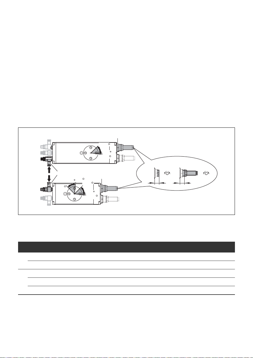
5.1.1 Einbauplatz
O Achten Sie auf genügend Einbauplatz für
– pneumatische Anschlüsse mit Drosselrückschlagventilen
und Justage des Zwischenstellungssystems (1),
– Montage der Sensorbefestigung (2)
Empfehlung: Montieren Sie den Sensor auf eine
gemeinsame Sensornutenseite.
– Justage des Endlagensystems mit Winkelstellung (3).
ACHTUNG
Abb. 3: Seitliche Abstände beim Einbau des Drehmoduls RCM

AVENTICS | RCM | R499050098–BDL–001–AD 13
1
Montage
5.1.2 Senkrecht einbauen
VORSICHT
Instabile Lage bei fehlender Druckluft
Ohne Druckluft hat der Drehflansch eventuell keine stabile
Lage und kann daher schlagartig zu drehen beginnen.
O Treffen Sie geeignete Sicherheitsvorkehrungen, dass
nach einem unerwarteten Druckluftausfall der
Drehflansch mit Aufbau ohne Gefährdung in eine stabile
Lage drehen kann.
O Sichern Sie vor dem Abschalten der Druckluft oder dem
Entlüften der Anlage den Drehflansch zum Beispiel durch
einen bewegten Bolzen (1).
Deutsch
Abb. 4: Sicherung des Drehflansches durch einen Bolzen (1)

14 AVENTICS | RCM | R499050098–BDL–001–AD
Montage
5.1.3 Drehmodul RCM auf einer Grundfläche
befestigen
Befestigungsschrauben (Drehflansch und Abschlussdeckel)
und Gewindestifte (Luftkanäle) dürfen nicht gelöst werden!
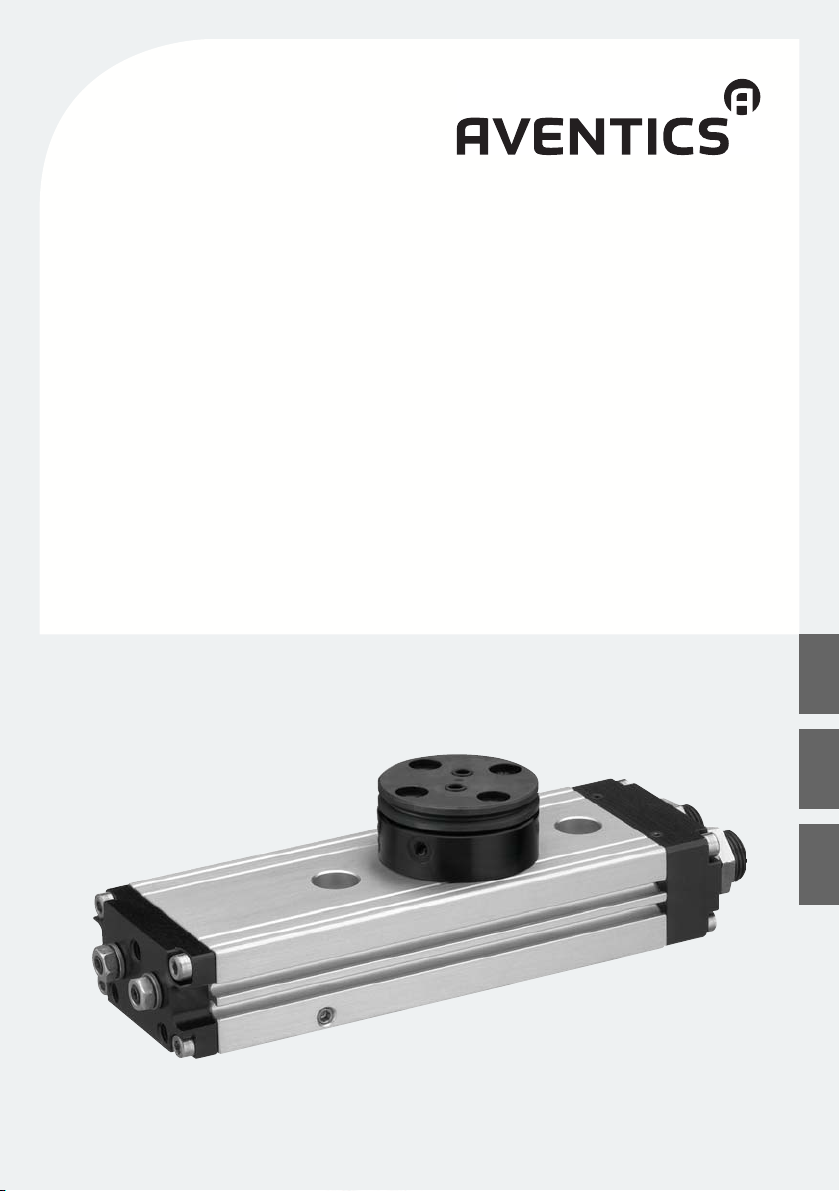
O Beachten Sie, dass das Drehmodul RCM auf allen drei
Auflagenflächen plan aufliegt.
Abb. 5: Anforderungen an die Auflage des Drehmoduls RCM auf der
Montagefläche
O Befestigen Sie das Drehmodul RCM mit mindestens
2 Befestigungsschrauben auf der Grundfläche.
Reproduzierbare Befestigungspositionen können mit
Zentrierhülsen erzeugt werden.

AVENTICS | RCM | R499050098–BDL–001–AD 15
12
RCM-06/-12 RCM-08/-16/-20/-25
5.1.4 Befestigungsvariante von oben
Abb. 6: Befestigung von oben über Durchgangsbohrungen
1 Befestigungsschraube
2 Zentrierhülse
5.1.5 Befestigungsvariante von unten
Montage
M
A
12
Abb. 7: Befestigung von unten über Gewindebohrungen
1 Befestigungsschraube
2 Zentrierhülse
Tabelle 3: Gewindetiefe T und Anzugsmomente M
RCM-06 RCM-08 RCM-12 RCM-16
T [mm] 7
MA [Nm] 3
T
M
A
12
A
T
RCM-20
RCM-25
(M4) (M5) (M5) (M6) (M8)
+0,5
0,3
9,1
+0,5
0,6
6
8,5
+0,5
0,6
6
11,1
10
+0,5
14,1
1
25
2,5
Deutsch
+1
16 AVENTICS | RCM | R499050098–BDL–001–AD
T
1
2
M
A
Montage
5.1.6 Nutzlast am Drehflansch befestigen
O Befestigen Sie die Nutzlast mit mindestens zwei Schrauben
und Zentrierhülsen auf dem Drehflansch (siehe Abb. 8).
Überstehende Schrauben
An der Drehflansch-Unterseite überstehende Schrauben
blockieren die Drehbewegung und führen zur Beschädigung
des Drehmoduls RCM.
O Verwenden Sie nur Schrauben mit passender Länge.
ACHTUNG
Abb. 8: Befestigung der Nutzlast auf dem Drehflansch
1 Befestigungsschraube
2 Zentrierhülse
Tabelle 4: Gewindetiefe T und Anzugsmomente M
RCM-06
RCM-08
(M3) (M4) (M5) (M6)
T [mm] 5
MA [Nm] 2,2 3,5 7 12
RCM-12
–1
–1
6
A
RCM-16
RCM-20
7
RCM-25
–1
–1
8

AVENTICS | RCM | R499050098–BDL–001–AD 17
x
m
J
u
Fx
m
v
m
Fy
Montage
5.1.7 Massenträgheitsmomente und Kräfte von
Nutzlasten
VORSICHT
Hohe Massenträgheitsmomente und Kräfte
Beim Überschreiten der maximal zulässigen
Massenträgheitsmomente und Kräfte kann es zu
Beschädigungen des Drehmoduls RCM und Verletzungen
kommen.
O Beachten Sie die max. zulässigen
Massenträgheitsmomente J und Kräfte Fx und Fy (Max.
Lagerbelastung).
Informationen hierzu finden Sie im Kapitel „Technische
Daten“ auf Seite 33.
Abb. 9: Massenträgheitsmomente und Kräfte am Drehmodul RCM
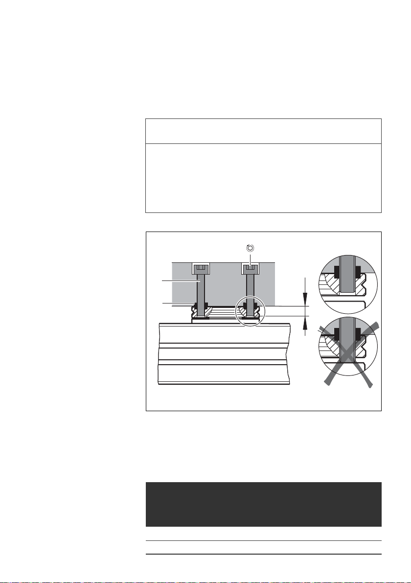
5.2 Druckluftanschlüsse
Verwechslungsgefahr der Druckluftanschlüsse
Die Druckluftanschlüsse A und B sind bei RCM und RCM-...-IP
nicht einheitlich angeordnet. Bei Verwechslung der
Anschlüsse kommt es zu Fehlfunktionen.
O Beachten Sie nachfolgende Hinweise zum richtigen
Anschluss der Druckluft.
Deutsch
ACHTUNG

18 AVENTICS | RCM | R499050098–BDL–001–AD
1
p
90
1800
A
B
0
90
180
A
B
C
p
RCM RCM-...-IP
p
A
B
90
0 18 0
0 18 0
A
B
C
p
90
RCM RCM-...-IP
Montage
5.2.1 Drosselrückschlagventile einbauen
Verwenden Sie abluftgedrosselte Drosselrückschlagventile (1)
zum Einstellen der Drehgeschwindigkeit.
1. Bauen Sie die Drosselrückschlagventile direkt in die
Druckluftanschlüssen ein.
2. Verschlauchen Sie die Drosselrückschlagventile.
3. Drehen Sie alle vorgeschalteten Drosselrückschlagventile
zunächst ganz zu.
4. Drehen Sie sie dann wieder eine Umdrehung auf.
5.2.2 Endlage 0° (linksdrehend) anfahren
1. Entlüften Sie Anschlüsse A und C (C nur bei RCM-...-IP).
2. Beaufschlagen Sie Anschluss B mit Druckluft.
Abb. 10: Druckluftanschluss B zum Anfahren der Endlage 0°
5.2.3 Endlage 90°/180° (rechtsdrehend) anfahren
1. Entlüften Sie Anschlüsse B und C (C nur bei RCM-...-IP).
2. Beaufschlagen Sie Anschluss A mit Druckluft.
Abb. 11: Druckluftanschluss A zum Anfahren der Endlage 90°/180°

AVENTICS | RCM | R499050098–BDL–001–AD 19
0180
90
A
B
C
p
MA = 6+5 Ncm
1.
3.
2.
Montage
5.2.4
Zwischenstellung 90° anfahren (nur bei RCM-...-IP)
1. Entlüften Sie Anschluss A und B.
2. Beaufschlagen Sie Anschluss C mit Druckluft.
Abb. 12: Druckluftanschluss C zum Anfahren der Zwischenstellung 90°
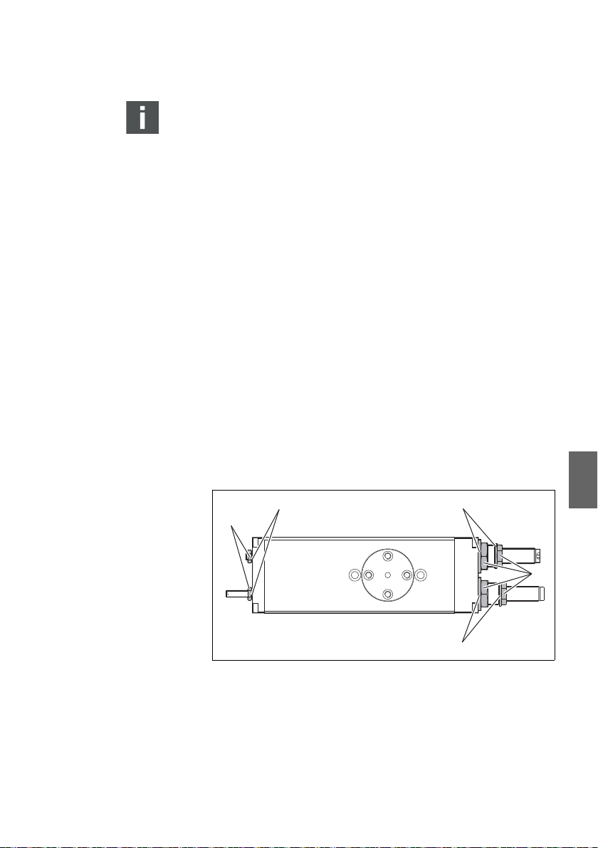
5.3 Magnetische Abtastung
5.3.1 Montage der Sensorbefestigung
O Zur Abfrage der Drehflansch-Endlagen und
Zwischenstellung montieren Sie den Sensor ST4 in die
Sensornuten.
Empfehlung O Montieren Sie den Sensor auf eine gemeinsame
Sensornutenseite.
Deutsch
Abb. 13: Montage des Sensors
5.3.2 Abtastsicherheit
Durch starke externe Magnetfelder (z. B. Schweißanlagen)
oder durch ferromagnetische Anbauteile, die unmittelbar
im Bereich des Abtastsystems angeordnet sind, kann es
möglicherweise zu einer Beeinträchtigung der
Abtastfunktion kommen.

20 AVENTICS | RCM | R499050098–BDL–001–AD
Inbetriebnahme
6 Inbetriebnahme
Arbeitsbereich des Drehmoduls
Im Arbeitsbereich des Drehmoduls kann es zu schweren
Verletzungen kommen.
O Stellen Sie sicher, dass im Betrieb niemand in den
Arbeitsbereich des Drehmoduls greift und keine
Körperteile erfasst werden können (z. B.
Schutzmaßnahme durch Schutzgitter).
Erst wenn die bewegliche Masse zum Stillstand
gekommen ist, darf ein Greifen an das Drehmodul
möglich sein.
O Stellen Sie sicher, dass sich im Arbeitsbereich des
Drehmoduls keine Fremdgegenstände befinden.
O Stellen Sie sicher, dass der Betriebsdruck in zulässigen
Bereich liegt (siehe „Technische Daten“ auf Seite 33).
O Verwenden Sie Drosselrückschlagventile (siehe
„Drosselrückschlagventile einbauen“ auf Seite 18).
VORSICHT
6.1 Endlagensystem (SE/SH) justieren
ACHTUNG
Endlagendämpfungselement zu tief eingedreht
Wird das Endlagendämpfungselement zu tief eingedreht,
kann es zu Fehlfunktionen und zur Beschädigung des
Drehmoduls kommen.
O Beachten Sie die Hinweise zur Einschraublänge (L) der
Endlagendämpfungselemente.
O Halten Sie die zulässigen Anzugsdrehmomente für die
Kontermutter ein (siehe Tab. 5 auf Seite 21 und Tab. 6 auf
Seite 22).

AVENTICS | RCM | R499050098–BDL–001–AD 21
A
B
45
-6
0
RCM
A
B
C
-6
45
0
RCM-...-IP
1
p
p
1
+
_
L
+
_
L
SE SH
2
2
3
3
Inbetriebnahme
O Wechseln Sie nach jedem zehnten Anziehen die
Dichtungsringe.
6.1.1 Endlage 0° justieren
1. Beaufschlagen Sie nur Anschluss B mit Druckluft (1).
2. Lösen Sie die Kontermutter (2) des
Endlagendämpfungselements (3).
3. Justieren Sie das Endlagendämpfungselement (3) auf die
gewünschte Endlageposition (siehe Detailbild).
4. Fixieren Sie das Endlagendämpfungselement (3) und ziehen
Sie die Kontermutter (2) wieder an.
5. Überprüfen Sie die Endlagenposition.
Abb. 14: Justieren der Endlage 0° (-6° bis 45°)
Tabelle 5: Schlüsselweite SW, Anzugsdrehmomente MA und Einschraublänge L
RCM-06 RCM-08 RCM-12 RCM-16 RCM-20 RCM-25
2 SW 81015191923
3 SW (SE/SH) 2,5
1)
[Nm] 4 8 10 20 20 25
M
A
(SE=SH) [mm] 4,7 5,2 6,5 9,5 9,5 9,5
L
min.
(SE=SH) [mm] 9 9,5 12,5 15 15 19
L
max.
Innensechskant
1)
/– 31)/– 61)/3
1)
81)/3
1)
81)/3
1)
Deutsch
101)/10
22 AVENTICS | RCM | R499050098–BDL–001–AD
1
RCM
B
180
90
45
96
186
135
A
p
RCM-...-IP
A
B
C
186
135
180
p
+
_
L
+
_
L
SE SH
2
2
3
3
Inbetriebnahme
6.1.2 Endlage 90o/180o justieren
1. Beaufschlagen Sie nur Anschluss A mit Druckluft (1).
2. Lösen Sie die Kontermutter (2) des
Endlagendämpfungselements (3).
3. Justieren Sie das Endlagendämpfungselement (3) auf die
gewünschte Endlageposition (siehe Detailbild).
4. Fixieren Sie das Endlagendämpfungselement und ziehen
Sie die Kontermutter (2) wieder an.
5. Überprüfen Sie die Endlagenposition.
Abb. 15: Justieren der Endlage 90° (45° – 96°) / 180° (135° – 186°)
Tabelle 6: Schlüsselweite SW, Anzugsdrehmomente MA und Einschraublänge L
RCM-06 RCM-08 RCM-12 RCM-16 RCM-20 RCM-25
2 SW 81015191923
[Nm] 4 8 10 20 20 25
M
A
3 SW (SE/SH) 2,5
(SE=SH) [mm] 4,7 5,2 6,5 9,5 9,5 9,5
L
min.
1)
Innensechskant
(SE=SH) [mm] 9 9,5 12,5 15,5 15 19
L
max.
1)
/– 31)/– 61)/3
1)
81)/3
1)
81)/3
1)
101)/10

AVENTICS | RCM | R499050098–BDL–001–AD 23
Inbetriebnahme
6.2 Zwischenstellungssystem (IP) justieren
ACHTUNG
Zwischenstellungsbolzen zu tief eingedreht
Wird der Zwischenstellungsbolzen zu tief eingedreht, kann es
zu Fehlfunktionen und zur Beschädigung des Drehmoduls
kommen.
O Beachten Sie die nachfolgenden Hinweise zur
Einschraublänge L
O Halten Sie das zulässige Anzugsdrehmoment MA für die
Kontermutter ein (siehe Tab. 7 auf Seite 24 und Tab. 8 auf
Seite 26).
O Wechseln Sie nach jedem zehnten Anziehen die
Dichtungsringe.
6.2.1 Zwischenstellung 70° – 90° justieren
der Zwischenstellungsbolzen.
min.
Angaben zur Schlüsselweite SW und zum Anzugsdrehmoment
finden Sie in Tab. 7 auf Seite 24.
M
A
1. Beaufschlagen Sie nur Anschluss C mit Druckluft (1).
2. Lösen Sie die Kontermutter (2) des
Zwischenstellungsbolzens (3) am Anschluss B.
3. Drehen Sie den Zwischenstellungsbolzen (3) bis zum
Anschlag heraus.
4. Lösen Sie die Kontermutter (4) des
Zwischenstellungsbolzens (5) am Anschluss A.
5. Justieren Sie den Zwischenstellungsbolzen (5) auf die
gewünschte Zwischenstellungsposition.
6. Fixieren Sie den Zwischenstellungsbolzen (5) und ziehen Sie
die Kontermutter (4) wieder an.
7. Drehen Sie den Zwischenstellungsbolzen (3) wieder hinein
bis am Drehflansch kein Winkelspiel mehr von Hand
spürbar ist.
Deutsch

24 AVENTICS | RCM | R499050098–BDL–001–AD
A
B
C
p
70
90
3
1
L
min.
5
4
+
_
L
min.
2
Inbetriebnahme
Überdrehen des Zwischenstellungsbolzens führt zu
mehrfachen Zwischenstellungen.
8. Fixieren Sie den Zwischenstellungsbolzen (3) und ziehen Sie
die Kontermutter (2) wieder an.
9. Überprüfen Sie die Zwischenstellungsposition.
Abb. 16: Justieren der Zwischenstellung 70° – 90°
Tabelle 7: Schlüsselweite SW, Anzugsdrehmoment MAund
Einschraublänge L
min.
RCM-12 RCM-16 RCM-20 RCM-25
2/4 SW 7 7 8 10
[Nm] 2,5 2,5 4 8
M
A
3/5 SW
1)
1)
[mm] 5567
L
min.
Innensechskant
222,53

AVENTICS | RCM | R499050098–BDL–001–AD 25
A
B
C
p
110
90
1
+
_
5
4
L
min.
L
min.
3
2
Inbetriebnahme
6.2.2 Zwischenstellung 90° – 110° justieren
Angaben zur Schlüsselweite SW und zum Anzugsdrehmoment
finden Sie in Tab. 8, auf Seite 26.
M
A
1. Beaufschlagen Sie nur Anschluss C mit Druckluft (1).
2. Lösen Sie die Kontermutter (4) des
Zwischenstellungsbolzens (5) am Anschluss A.
3. Drehen Sie den Zwischenstellungsbolzen (5) bis zum
Anschlag heraus.
4. Lösen Sie Kontermutter (2) des Zwischenstellungsbolzens
(3) am Anschluss B.
5. Justieren Sie den Zwischenstellungsbolzen (3) auf die
gewünschte Zwischenstellungsposition.
6. Fixieren Sie den Zwischenstellungsbolzen (3) und ziehen Sie
die Kontermutter (2) wieder an.
7. Drehen Sie den Zwischenstellungsbolzen (5) wieder hinein
bis am Drehflansch kein Winkelspiel mehr von Hand
spürbar ist.
Überdrehen des Zwischenstellungsbolzens führt zu
mehrfachen Zwischenstellungen.
8. Fixieren Sie den Zwischenstellungsbolzen (5) und ziehen Sie
Kontermutter (4) wieder an.
9. Überprüfen Sie die Zwischenstellungsposition.
Deutsch
Abb. 17: Justieren der Zwischenstellung 90° – 110°

26 AVENTICS | RCM | R499050098–BDL–001–AD
1
2
2
1
0
T
D
1
0
1
3
2
4
3
2
4
T
D
Inbetriebnahme
Tabelle 8: Schlüsselweite SW, Anzugsdrehmomente M
Einschraublänge L
min.
und
A
RCM-12 RCM-16 RCM-20 RCM-25
2/4 SW 7 7 8 10
[Nm] 2,5 2,5 4 8
M
A
3/5 SW
L
min.
1)
Innensechskant
1)
[mm] 5567
222,53
6.3 Luftdurchführung (AP) anschließen
Maximal zulässiger Druck: 8 bar.
Abb. 18: 2-fach Luftdurchführung (bei Endlagenposition 0°)
Abb. 19: 4-fach Luftdurchführung (bei Endlagenposition 0°)
Tabelle 9: Anschlussgewinde der Luftdurchführung
RCM-12 RCM-16 RCM-20 RCM-25
D M3M3M5M5
T [mm] 4 4 5 5

AVENTICS | RCM | R499050098–BDL–001–AD 27
1.
2.
1x
Inbetriebnahme
6.4 Belüften
1. Drehen Sie alle vorgeschalteten Drosselrückschlagventile
zunächst ganz zu.
2. Drehen Sie sie dann wieder eine Umdrehung auf.
O Stellen Sie sicher, dass die Betriebsbedingungen in den
zulässigen Bereichen liegen (siehe Kapitel 11 „Technische
Daten“ auf Seite 33).
O Belüften Sie eine der beiden Drehmodul-
Druckluftanschlüsse durch langsame Belüftung.
Der Drehflansch dreht in eine Endlage.
6.5 Probelauf
1. Prüfen Sie, ob die folgenden Punkte zu verändern sind.
– die Geschwindigkeit und die Beschleunigung der
beweglichen Masse
– die Endlagenposition (nur bei Stillstand des
Drehflansches)
– die Masse der Nutzlast (nur bei Stillstand des
Drehflansches)
– die Position des Sensors (nur bei Stillstand des
Drehflansches)
Deutsch
2. Drehen Sie die Drosselrückschlagventile wieder langsam
auf, bis die gewünschte Drehgeschwindigkeit eingestellt ist.
Dabei darf die maximal zulässige Geschwindigkeit nicht
überschritten werden (siehe „Schwenkzeit“ im Kapitel
„Technische Daten“ auf Seite 33).
Der Drehflansch soll die Endlage sicher erreichen, aber
nicht hart anschlagen. Zu hartes Anschlagen bewirkt ein
Rückprellen des Drehflansches aus der Endlage.

28 AVENTICS | RCM | R499050098–BDL–001–AD
Wartung
3. Bei hörbar hartem Anschlagen des Drehflansches
unterbrechen Sie den Probelauf.
Ursachen für hartes Anschlagen können sein:
– bewegliche Masse zu hoch
– Drehgeschwindigkeit zu hoch
– kein Druckluftpolster auf der Abluftseite.
4. Sorgen Sie für Abhilfe der obengenannten Ursachen.
5. Wiederholen Sie den Probelauf nach erfolgter Durchführung
aller notwendigen Korrekturen.
6. Beenden Sie den Probelauf und befestigen Sie den Sensor
endgültig.
7 Wartung
Anlage steht im Betrieb unter Druck!
Arbeiten an der Anlage unter Druck kann zu Beschädigungen
am Drehmodul RCM und zu Verletzungen führen!
O Entlüften Sie vor Arbeiten die gesamte Anlage und alle
angeschlossenen Geräte.
VORSICHT
Am Drehmodul RCM müssen – abhängig vom Nutzungsgrad –
folgende Wartungsarbeiten durchgeführt werden:
Tabelle 10: Wartung am Drehmodul RCM
Wartungstätigkeit Ver sion en Intervall
Dichtungsringe wechseln RCM nach jedem 10. Anziehen
Hydraulische Stoßdämpfer überprüfen RCM-...-SH Empfehlung:
Schmieren RCM die Lager sind wartungsfrei
nach 3 Mio. Drehbewegungen
AVENTICS | RCM | R499050098–BDL–001–AD 29
2
1
2
2
1
Wartung
Reparaturen am Drehmodul RCM, die über die in Tab. 10
genannten Tätigkeiten hinausgehen, sind nicht zulässig.
Bei technische Problemen wenden Sie sich bitte an Ihre
AVENTICS Serviceabteilung.
7.1 Dichtungsringe wechseln
Dichtungsringe müssen gewechselt werden
W im Endlagensystem und
W im Zwischenstellungssystem.
So wechseln Sie die Dichungen:
1. Lösen die Kontermutter (1) des jeweiligen Systems
2. Entfernen Sie die alte Dichtung (2).
3. Montieren Sie die neue Dichtung durch Eindrehen des
Dichtungsringes auf das Gewinde.
4. Ziehen Sie die Kontermutter wieder fest (die geforderten
Anzugsmomente finden Sie im Kapitel 6 „Inbetriebnahme“
ab Seite 20).
Deutsch
Abb. 20: Dichtungsringe wechseln am Drehmodul RCM

30 AVENTICS | RCM | R499050098–BDL–001–AD
2
1
Wartung
7.2 Hydraulische Stoßdämpfer wechseln
O Entlüften Sie die Anlage.
O Sichern Sie den Drehflansch gegen unkontrolliertes
Rotieren.
1. Lösen Sie die Kontermutter (1) des Stoßdämpfers.
2. Drehen Sie den alten Stoßdämpfer (2) aus der
Anschlaghülse heraus.
3. Drehen Sie den neuen Stoßdämpfer bis zum Endanschlag in
die Anschlaghülse hinein.
4. Fixieren Sie den Stoßdämpfer und ziehen Sie die
Kontermutter (1) wieder an.
5. Justieren Sie das Endlagensystem neu (siehe
„Endlagensystem (SE/SH) justieren“ auf Seite 20).
Abb. 21: Hydraulische Stoßdämpfer wechseln
Tabelle 11: Schlüsselweiten SW und Anzugsdrehmomente M
RCM-12 RCM-16 RCM-20 RCM-25
SW 11 13 15 17
1
M
A
SW 3
2
1)
Innensechskant
4 6 10 15
1)
1)
3
A
1)
3
10

AVENTICS | RCM | R499050098–BDL–001–AD 31
Reinigung und Pflege
8 Reinigung und Pflege
VORSICHT
Anlage steht im Betrieb unter Druck!
Arbeiten an der Anlage unter Druck kann zu Beschädigungen
und Verletzungen führen!
O Entlüften Sie vor Arbeiten die gesamte Anlage und alle
angeschlossenen Geräte.
8.1 Drehmodul RCM reinigen
1. Entlüften Sie die Anlage.
2. Sichern Sie den Drehflansch gegen unkontrolliertes
Rotieren.
3. Reinigen Sie das Drehmodul RCM nur mit einem leicht
angefeuchteten Lappen (z. B. mit Waschbenzin, Seifenlauge
bis 60 °C oder einem anderen neutralen Reinigungsmittel).
9 Entsorgung
Beachten Sie die lokalen Bestimmungen zur Entsorgung.
Deutsch

32 AVENTICS | RCM | R499050098–BDL–001–AD
Fehlerbehebung
10 Fehlerbehebung
Störung Mögliche Ursache Abhilfe
Ungleichförmige Drehbewegung
der beweglichen Masse
Hartes Anschlagen in der
Endlage
Drehmodul bewegt sich nicht Druckluftversorgung fehlt Druckluftversorgung überprüfen
Drehmodul bewegt sich sehr
langsam
Drehmodul arbeitet nicht über
den vollen Drehbereich
Drehmodul bleibt in der
Zwischenstellung stehen
Drosseln falsch eingesetzt Drosselfunktionen (Zu- oder
Geschwindigkeit zu hoch Geschwindigkeit reduzieren
keine oder zu geringe Dämpfung Dämpfungselemente neu
fehlendes Luftpolster Gleichzeitige Belüftung beider
Stoßdämpfer defekt Stoßdämpfer wechseln
Nutzlast zu groß Nutzlast reduzieren
Verschlauchungsfehler Verschlauchung und Blindstopfen
Nutzlast zu groß Nutzlast reduzieren
Steuerimpuls fehlt Steuerventil überprüfen
Sensor defekt Sensor wechseln
Druckluftversorgung zu niedrig Druckluftversorgung überprüfen
Dichtungsringe defekt Dichtungsringe wechseln
Drosseln falsch eingestellt Drosseleinstellung überprüfen
Kolbendichtung defekt Drehmodul muss von AVENTICS
Endlagensystem falsch
eingestellt
Verschlauchungsfehler Verschlauchung überprüfen
Drehmodul defekt Drehmodul muss von AVENTICS
Abluft) überprüfen
justieren
Druckluftanschlüsse mit
anschließender Entlüftung einer
Seite
überprüfen
geprüft werden
Endlagensystem überprüfen
geprüft werden

AVENTICS | RCM | R499050098–BDL–001–AD 33
Technische Daten
11 Technische Daten
RCM-06 RCM-08 RCM-12 RCM-16 RCM-20 RCM-25
Anschlussgewinde M3 M3 M5 M5 M5 M5
Betriebsdruckbereich [bar]
W RCM 2 – 82 – 82 – 82 – 82 – 82 – 8
W RCM-...-IP (mit integr. Zwischenstellung) – – 4 – 8 4 – 8 4 – 8 4 – 8
W
RCM-...-AP (mit Luftdurchführung)
W RCM-...-AP (mit Luftdurchführung)
...-IP (mit integr. Zwischenstellung)
Temperaturbereich [°C] +5 bis +60
1)
Theoretisches Drehmoment
Maximal zulässiges Massenträgheitsmoment
2
]
[kg cm
W elastisch
W hydraulisch
Minimale Schwenkzeit (1 x 180°) [s]
W RCM-...
-SE elastisch 0,12 0,16 0,16 0,2 0,25 0,25
-SE elastisch
-IP mit integr. Zwischenstellung
-SH hydraulisch – – 0,3 0,32 0,48 0,6
-SH hydraulisch
-IP mit integr. Zwischenstellung
W RCM-...-AP (mit Luftdurchführung)
-SE elastisch – 0,28 0,28 0,25 0,3 0,3
-SE elastisch
-IP mit integr. Zwischenstellung
-SH hydraulisch – – 0,3 0,32 0,48 0,6
-SH hydraulisch
-IP mit integr. Zwischenst.
Max. Lagerbelastung [N]
W Fx (axial)
W Fy (radial), RCM
W Fy (radial), RCM-...-AP
Medium Druckluft, Ölgehalt 0 – 1 mg/m³
Einbaulage beliebig
1)
Bei 6 bar. Bedingt durch das Konstruktionsprinzip wirkt in der Endlage ein vermindertes theoretisches Drehmoment.
[Nm] 0,17 0,33 0,95 1,7 3 6,5
– 3,5 – 8 2,5 – 8 2 – 8 2 – 8 2 – 8
– – 4 – 84 – 84 – 84 – 8
0,08–0,25–0,7
– – 0,28 0,25 0,3 0,3
– – 0,30,320,480,6
– – 0,32 0,3 0,35 0,35
– – 0,3 0,32 0,48 0,65
170
170
280
300
–
210
10
330
360
290
1,6
80
490
580
400
3,2
180
620
780
560
6,3
450
1160
1480
700
Deutsch

34 AVENTICS | RCM | R499050098–BDL–001–AD
Stichwortverzeichnis
12 Stichwortverzeichnis
W A
Abtastsicherheit 19
W B
Befestigungsvarianten
von oben 15
von unten 15
Belüften 27
Bestimmungsgemäßer Gebrauch 7
W D
Dichtungsringe wechseln 29
Drehmodul reinigen 31
Drosselrückschlagventil 18
W E
Einbau
auf einer Grundfläche 14
Einbauplatz 12
senkrecht 13
Endlage justieren 20
0 Grad 21
90/180 Grad 22
Endlagen anfahren 18
Entsorgung 31
W F
Fehlerbehebung 32
Funktionsweise 11
W H
Hydraulische Stoßdämpfer wechseln 30
W M
Magnetische Abtastung 19
Massenträgheitsmomente 17
W N
Nicht bestimmungsgemäßer Gebrauch 7
Nutzlast befestigen 16
W P
Probelauf 27
W Q
Qualifikation des Personals 8
W R
Reinigung 31
W S
Sensor 19
Sicherheitshinweise 9
W T
Technische Daten 33
W W
Wartung 28
W Z
Zwischenstellung anfahren 19
Zwischenstellung justieren 23
70 - 90 Grad 23
90 - 110 Grad 25
W L
Lieferumfang 9
Luftdurchführung (AP) anschließen 26

AVENTICS | RCM | R499050098–BDL–001–AD 35
Contents
Contents
1 About this document ................................................... 37
1.1 Documentation validity..........................................................37
1.2 Presentation of information.................................................37
1.2.1 Safety instructions ................................................................ 37
1.2.2 Symbols ................................................................................... 38
2 For your safety ............................................................ 39
2.1 About this chapter...................................................................39
2.2 Intended use..............................................................................39
2.3 Improper use ............................................................................40
2.4 Personnel qualifications........................................................40
2.5 General safety instructions..................................................41
3 Delivery contents ........................................................ 41
4 Device description ...................................................... 42
4.1 Function/variants....................................................................43
5 Assembly ..................................................................... 44
5.1 Installation and mounting.....................................................44
5.1.1 Installation space .................................................................. 44
5.1.2 Install vertically ...................................................................... 45
5.1.3 Mounting the RCM rotary compact module on
a base ........................................................................................ 46
5.1.4 Fastening variant from above ........................................... 47
5.1.5 Fastening variant from below ........................................... 47
5.1.6 Fastening useful loads on the rotary flange ................. 48
5.1.7 Mass moments of inertia and forces from
useful loads ............................................................................. 49
5.2 Compressed air connections ...............................................50
5.2.1 Installing check-choke valves ........................................... 50
5.2.2 Moving to end position 0° (counterclockwise) .............. 50
5.2.3 Moving to end position 90°/180° (clockwise) ............... 51
5.2.4 Moving to intermediate position 90°
(only in RCM-...-IP) ................................................................. 51
5.3 Magnetic proximity switching..............................................51
5.3.1 Sensor assembly ................................................................... 51
5.3.2 Proximity switching reliability ........................................... 52
English

36 AVENTICS | RCM | R499050098–BDL–001–AD
Contents
6 Commissioning ............................................................ 52
6.1 Adjusting the end position system (SE/SH) ....................53
6.1.1 Adjusting the end position 0° ............................................ 54
6.1.2 Adjusting the end position 90
6.2 Adjusting the intermediate position system (IP)............56
6.2.1 Adjusting the intermediate position 70° – 90° ............. 56
6.2.2 Adjusting the intermediate position 90° – 110° ........... 57
6.3 Connecting the air ducts (AP) ..............................................59
6.4 Ventilating..................................................................................59
6.5 Trial run......................................................................................60
7 Maintenance ................................................................ 61
7.1 Changing the sealing rings...................................................62
7.2 Changing the hydraulic shock absorber...........................62
8 Cleaning and servicing ............................................... 64
8.1 Cleaning the RCM rotary compact module......................64
9 Disposal ....................................................................... 64
10 Troubleshooting .......................................................... 65
11 Technical data ............................................................. 66
12 Index ............................................................................. 67
o
o ........................................ 55
/180

AVENTICS | RCM | R499050098–BDL–001–AD 37
About this document
1 About this document
1.1 Documentation validity
These instructions contain important information on the safe
and appropriate assembly, operation, and maintenance of the
RCM rotary compact module and how to remedy simple
malfunctions yourself.
O Read this documentation completely, especially chapter
“For your safety” on page 39, before working with the
product.
1.2 Presentation of information
To allow you to begin working with the product quickly and
safely, uniform safety instructions, symbols, terms, and
abbreviations are used in this documentation. For better
understanding, these are explained in the following sections.
1.2.1 Safety instructions
This documentation contains safety instructions before any
steps that involve a risk of personal injury or damage to
property. The measures described to avoid these hazards must
be observed.
Safety instructions are set out as follows:
SIGNAL WORD
Hazard type and source
Consequences
O Precautions
English

38 AVENTICS | RCM | R499050098–BDL–001–AD
About this document
W Safety sign: draws attention to the risk
W Signal word: identifies the degree of hazard
W Hazard type and source: identifies the hazard type and
source
W Consequences: describes what occurs when the safety
instructions are not complied with
W Precautions: states how the hazard can be avoided
Table 1: Hazard classes according to ANSI Z 535.6-2006
Safety sign, signal word Meaning
DANGER
WARNING
CAUTION
NOTICE
Indicates a hazardous situation
which, if not avoided, will certainly
result in death or serious injury.
Indicates a hazardous situation
which, if not avoided, could result in
death or serious injury.
Indicates a hazardous situation
which, if not avoided, could result in
minor or moderate injury.
Indicates that damage may be
inflicted on the product or the
environment.
1.2.2 Symbols
The following symbols indicate information that is not relevant
for safety but that assists in comprehending the documentation.
Table 2: Meaning of the symbols
Symbol Meaning
If this information is disregarded, the product cannot be
used or operated optimally.
O
1.
2.
3.
Individual, independent action
Numbered steps:
The numbers indicate sequential steps.

AVENTICS | RCM | R499050098–BDL–001–AD 39
For your safety
2 For your safety
2.1 About this chapter
The product has been manufactured according to the accepted
rules of safety and current technology. There is, however, still a
danger of personal injury or damage to equipment if the
following general safety instructions and the warnings before
the steps contained in these instructions are not complied with.
O Read these instructions completely before working with the
product.
O Keep these instructions in a location where they are
accessible to all users at all times.
O Always include the operating instructions when you pass
the bus coupler on to third parties.
2.2 Intended use
The product may be used as follows:
W only for industrial applications. An individual license must
be obtained from the authorities or an inspection center for
systems that are to be used in a residential area (residential,
business, and commercial areas).
W only within the performance range provided in the technical
data
The product is intended for professional use only.
Intended use includes having read and understood this
documentation, especially the chapter “For your safety”.
English

40 AVENTICS | RCM | R499050098–BDL–001–AD
For your safety
2.3 Improper use
Any use other than that described under Intended use is
improper and is not permitted.
The installation or use of unsuitable products in safety-relevant
applications can result in unanticipated operating states in the
application that can lead to personal injury or damage to
equipment. Therefore, only use a product in safety-relevant
applications if such use is specifically stated and permitted in
the product documentation. For example, in areas with
explosion protection or in safety-related components of control
systems (functional safety).
AVENTICS GmbH is not liable for any damages resulting from
improper use. The user alone bears the risks of improper use of
the product.
Improper use of the bus coupler includes:
W changing or conversion of the product,
W use for any application not stated in these instructions, or
W use under operating conditions that deviate from those
described in these instructions.
2.4 Personnel qualifications
Assembly, disassembly, commissioning, and operation require
basic electrical and pneumatic knowledge, as well as
knowledge of the appropriate technical terms. Assembly,
disassembly, commissioning, and operation may therefore only
be carried out by qualified electrical or pneumatic personnel or
an instructed person under the direction and supervision of
qualified personnel.
Qualified personnel are those who can recognize possible
hazards and institute the appropriate safety measures due to
their professional training, knowledge, and experience, as well
as their understanding of the relevant conditions pertaining to
the work to be done. Qualified personnel must observe the rules
relevant to the subject area.

AVENTICS | RCM | R499050098–BDL–001–AD 41
Delivery contents
2.5 General safety instructions
W Observe the regulations for accident prevention and
environmental protection for the country where the product
is used and at the workplace.
W Do not change or modify the device.
W Only use the device within the performance range provided
in the technical data.
W AVENTICS drives are designed for oil-free operation when
used as intended.
W Only use one type of medium throughout the entire product
service life, e.g. always use oil-free compressed air.
W Do not use any compressed air blowers or water jet devices
in the RCM rotary compact module’s work area.
W Only use AVENTICS products that are in perfect working
order.
W Follow all the instructions on the product.
W Persons who assemble, operate, disassemble, or maintain
AVENTICS products must not consume any alcohol, drugs,
or pharmaceuticals that may affect their ability to respond.
W To avoid injuries due to unsuitable spare parts, only use
accessories and spare parts approved by the manufacturer.
3 Delivery contents
The delivery consists of the following components:
W RCM rotary compact module
W 2x centering sleeves
Only for variants with air ducts (AP)
W 2 x O-rings (RCM-08/-12-...-AP)
W 4 x O-rings (RCM-16/.../-25-...-AP)
English

42 AVENTICS | RCM | R499050098–BDL–001–AD
12 345 67
810 9
Device description
4 Device description
Fig. 1: Overview of the RCM rotary compact module (design with integrated intermediate position,
integrated air ducts, and elastic cushioning element)
1 Intermediate position system (IP)
2 Base
3 Threaded/through holes with
countersinking to fasten the RCM rotary
compact module
4 Threaded holes with countersinking
tofasten useful loads
5 Rotary flange
6 End cover
7 End position system (with angle
adjustment and cushioning)
– Elastic cushioning (SE)
– Hydraulic cushioning (SH)
8 Air ducts (AP)
9 Sensor grooves
10 Compressed air connections

AVENTICS | RCM | R499050098–BDL–001–AD 43
00123274
1
65
4
32
7
Device description
4.1 Function/variants
The RCM rotary compact module is driven by two double-acting
pistons (diagram on left). The pistons synchronously transfer
the force to the ball-bearing pinion via rack elements.
Two variants are available for the end position system with
angle adjustment:
W with elastic end cushioning element or
W with hydraulic end cushioning element.
Additional optional variants include those with integrated air
ducts and integrated intermediate position (diagram on left).
Fig. 2: RCM rotary compact module with variants
1 Integrated intermediate position (IP)
2 Integrated air ducts (AP)
English
3 Elastic end cushioning element (SE)
4 Hydraulic end cushioning element (SH)
5 Shock absorber
6 Lock nut for shock absorber
7 Stop sleeve for angle adjustment

44 AVENTICS | RCM | R499050098–BDL–001–AD
1
2
2
3
Assembly
5 Assembly
Damage to the rotary compact module
Strong impacts on the RCM rotary compact module may
damage the rotary flange.
O Do not permit impacts on the rotary flange, use a suitable
tool and follow the assembly instructions.
5.1 Installation and mounting
5.1.1 Installation space
O Make sure there is enough installation space for
– pneumatic connections with check-choke valves and
adjustment of the intermediate position system (1),
– assembly of the sensor (2)
Recommendation: Mount the sensor on the same side of
the sensor groove.
– adjustment of the end position system with angle
adjustment (3).
NOTICE
Fig. 3: Lateral distances when installing the RCM rotary compact
module

AVENTICS | RCM | R499050098–BDL–001–AD 45
1
Assembly
5.1.2 Install vertically
CAUTION
Instable position with insufficient compressed air
If there is not enough compressed air, the rotary flange might
not have a stable position and start to rotate abruptly.
O Take safety precautions so that, if there is an unexpected
loss of compressed air, the rotary flange and its
attachments can move into a stable position without any
danger.
O Secure the rotary flange, e.g. with a moving bolt (1),
before switching off the compressed air or ventilating the
system.
English
Fig. 4: Securing the rotary flange with a bolt (1)

46 AVENTICS | RCM | R499050098–BDL–001–AD
Assembly
5.1.3 Mounting the RCM rotary compact module on
a base
Mounting screws (rotary flange and end cover) and
threaded pins (air channels) may not be loosened!
O Make sure that the RCM rotary compact module is flat on all
three bearing surfaces.
Fig. 5: Requirements for placing the RCM rotary compact module on
the mounting surface
O Fasten the RCM rotary compact module to the base with at
least 2 mounting screws.
Reproducible mounting positions can be created with
centering sleeves.

AVENTICS | RCM | R499050098–BDL–001–AD 47
12
RCM-06/-12 RCM-08/-16/-20/-25
5.1.4 Fastening variant from above
Fig. 6: Fastening from above with through holes
1 Mounting screw
2 Centering sleeve
5.1.5 Fastening variant from below
Assembly
M
A
12
Fig. 7: Fastening from below with threaded holes
1 Mounting screw
2 Centering sleeve
Table 3: Thread depth T and tightening torque M
RCM-06 RCM-08 RCM-12 RCM-16
T [mm] 7
MA [Nm] 3
T
M
A
12
A
T
RCM-20
RCM-25
(M4) (M5) (M5) (M6) (M8)
+0,5
0,3
9,1
+0,5
0,6
6
8,5
+0,5
0,6
6
11,1
10
+0,5
14,1
1
25
2,5
English
+1

48 AVENTICS | RCM | R499050098–BDL–001–AD
T
1
2
M
A
Assembly
5.1.6 Fastening useful loads on the rotary flange
O Fasten the useful load on the rotary flange with at least two
screws and centering sleeves (see Fig. 8).
Protruding screws
Screws protruding from the bottom of the rotary flange will
block the rotary movement and damage the RCM rotary
compact module.
O Only use screws with the suitable length.
NOTICE
Fig. 8: Fastening the useful load on the rotary flange
1 Mounting screw
2 Centering sleeve

AVENTICS | RCM | R499050098–BDL–001–AD 49
x
m
J
u
Fx
m
v
m
Fy
Assembly
Table 4: Thread depth T and tightening torque M
RCM-06
RCM-08
(M3) (M4) (M5) (M6)
T [mm] 5
MA [Nm] 2,2 3,5 7 12
RCM-12
–1
–1
6
A
RCM-16
RCM-20
7
RCM-25
–1
5.1.7 Mass moments of inertia and forces from
useful loads
CAUTION
High mass moments of inertia and forces
Exceeding the mass moments of inertia and forces may lead
to damage to the RCM rotary compact module, as well as
injuries.
O Observe the max. permissible mass moments of inertia J
and forces Fx and Fy (max. bearing load).
Information on this can be found in the chapter
“Technical data” on page 66.
–1
8
Fig. 9: Mass moments of inertia and forces on the RCM rotary compact module
English

50 AVENTICS | RCM | R499050098–BDL–001–AD
1
p
90
1800
A
B
0
90
180
A
B
C
p
RCM RCM-...-IP
Assembly
5.2 Compressed air connections
Danger of confusion of the compressed air connections
The compressed air connections A and B are not uniformly
arranged in the RCM and RCM-...-IP. Malfunctions will occur if
these connections are confused.
O Observe the following notes to correctly connect the
compressed air.
5.2.1 Installing check-choke valves
Use exhaust throttled check-choke valves (1) to set the rotating
speed.
1. Install the check-choke valves directly in the compressed air
connections.
2. Connect hoses to the check-choke valves.
3. First, turn off all of the upstream check-choke valves until
they are completely closed.
4. Then open them again by turning them by one turn.
CAUTION
5.2.2 Moving to end position 0° (counterclockwise)
1. Exhaust connections A and C (C only in RCM-...-IP).
2. Apply compressed air to connection B.
Fig. 10: Compressed air connection B to move to end position 0°

AVENTICS | RCM | R499050098–BDL–001–AD 51
p
A
B
90
0 18 0
0 18 0
A
B
C
p
90
RCM RCM-...-IP
0180
90
A
B
C
p
5.2.3 Moving to end position 90°/180° (clockwise)
1. Exhaust connections B and C (C only in RCM-...-IP).
2. Apply compressed air to connection A.
Fig. 11: Compressed air connection A to move to end position 90°/180°
5.2.4 Moving to intermediate position 90°
(only in RCM-...-IP)
1. Exhaust connections A and B.
2. Apply compressed air to connection C.
Assembly
Fig. 12: Compressed air connection C to move to intermediate position
90°
English
5.3 Magnetic proximity switching
5.3.1 Sensor assembly
O Mount the ST4 sensor in the sensor grooves for position
inquiry of the rotary flange end positions and intermediate
Tip O Mount the sensor on the same side of the sensor groove.
position.

52 AVENTICS | RCM | R499050098–BDL–001–AD
MA = 6+5 Ncm
1.
3.
2.
Commissioning
Fig. 13: Mounting the sensor
5.3.2 Proximity switching reliability
Strong external magnetic fields (e.g. welding systems) or
ferromagnetic attachments that are directly located near
the proximity switching system may impair the function.
6 Commissioning
Rotary compact module work area
Severe injuries may occur in the rotary compact module
work area.
O Make sure that no one can reach into the rotary compact
module work area and that no extremities can be caught
(e.g. implement measures such as protective grids).
The rotary compact module may only be handled after
the moving masses have come to a standstill.
O Make sure that there are no foreign objects in the rotary
compact module work area.
CAUTION
O Make sure that the working pressure is within the
permissible range (see “Technical data” on page 66).
O Use check-choke valves (see “Installing check-choke
valves” on page 50).

AVENTICS | RCM | R499050098–BDL–001–AD 53
Commissioning
6.1 Adjusting the end position system (SE/SH)
NOTICE
End cushioning element screwed in too far
Malfunctions and damage to the rotary compact module may
occur if the end cushioning element has been screwed in too
far.
O Observe the notes on the reach of the screw (L) for the
end cushioning elements.
O Maintain the permissible tightening torques for the lock nuts
(see Table 5 on page 54 and Table 6 on page 55).
O Change the sealing rings after every tenth tightening.
English

54 AVENTICS | RCM | R499050098–BDL–001–AD
A
B
45
-6
0
RCM
A
B
C
-6
45
0
RCM-...-IP
1
p
p
1
+
_
L
+
_
L
SE SH
2
2
3
3
Commissioning
6.1.1 Adjusting the end position 0°
1. Only apply compressed air (1) to connection B.
2. Loosen the lock nut (2) for the end cushioning element (3).
3. Adjust the end cushioning element (3) to the desired end
position (see detailed figure).
4. Fasten the end cushioning element (3) and retighten the lock
nut (2).
5. Check the end position.
Fig. 14: Adjusting the end position 0° (-6° to 45°)
Table 5: Wrench size SW, tightening torques MA and reach of screw L
RCM-06 RCM-08 RCM-12 RCM-16 RCM-20 RCM-25
2 SW 81015191923
[Nm] 4 8 10 20 20 25
M
A
3 SW (SE/SH) 2,5
1)
(SE=SH) [mm] 9 9,5 12,5 15 15 19
L
max.
Hexagon socket
(SE=SH) [mm] 4,7 5,2 6,5 9,5 9,5 9,5
L
min.
1)
/– 31)/– 61)/3
1)
81)/3
1)
81)/3
1)
101)/10

AVENTICS | RCM | R499050098–BDL–001–AD 55
1
RCM
B
180
90
45
96
186
135
A
p
RCM-...-IP
A
B
C
186
135
180
p
+
_
L
+
_
L
SE SH
2
2
3
3
Commissioning
6.1.2 Adjusting the end position 90o/180
o
1. Only apply compressed air (1) to connection A
2. Loosen the lock nut (2) for the end cushioning element (3).
3. Adjust the end cushioning element (3) to the desired end
position (see detailed figure).
4. Fasten the end cushioning element (3) and retighten the lock
nut (2).
5. Check the end position.
Fig. 15: Adjusting the end position 90° (45° – 96°) / 180° (135° – 186°)
Table 6: Wrench size SW, tightening torques MA and reach of screw L
RCM-06 RCM-08 RCM-12 RCM-16 RCM-20 RCM-25
2 SW 81015191923
[Nm] 4 8 10 20 20 25
M
A
3 SW (SE/SH) 2,5
(SE=SH) [mm] 4,7 5,2 6,5 9,5 9,5 9,5
L
min.
(SE=SH) [mm] 9 9,5 12,5 15,5 15 19
L
max.
1)
Hexagon socket
1)
/– 31)/– 61)/3
1)
81)/3
1)
81)/3
1)
101)/10
English

56 AVENTICS | RCM | R499050098–BDL–001–AD
Commissioning
6.2 Adjusting the intermediate position system
(IP)
Intermediate position bolt screwed in too far
Malfunctions and damage to the rotary compact module may
occur if the intermediate position bolt has been screwed in
too far.
O Observe the following notes on the reach of the screw
for the intermediate position bolts.
L
min.
O Maintain the permissible tightening torque MA for the lock
nut (see Table 7 on page 57 and Table 8 on page 58).
O Change the sealing rings after every tenth tightening.
6.2.1 Adjusting the intermediate position 70° – 90°
Information on the wrench size SW and tightening torque MA
can be found in Table 7 on page 57.
1. Only apply compressed air (1) to connection C.
2. Loosen the lock nut (2) for the intermediate position bolt (3)
at connection B.
3. Unscrew the intermediate position bolt (3) up to the stop.
4. Loosen the lock nut (4) for the intermediate position bolt (5)
at connection A.
5. Adjust the intermediate position bolt (5) to the desired
intermediate position.
6. Fasten the intermediate position bolt (5) uand retighten the
lock nut (4).
7. Screw the intermediate position bolt (3) back in until no
angle play can be felt by hand at the rotary flange.
NOTICE
Screwing the intermediate position bolt in too far will result
in multiple intermediate positions.

AVENTICS | RCM | R499050098–BDL–001–AD 57
A
B
C
p
70
90
3
1
L
min.
5
4
+
_
L
min.
2
8. Fasten the intermediate position bolt (3) and retighten the
lock nut (2).
9. Check the intermediate position.
Fig. 16: Adjusting the intermediate position 70° – 90°
Commissioning
Table 7: Wrench size SW, tightening torques MA and reach of
screw L
min.
RCM-12 RCM-16 RCM-20 RCM-25
2/4 SW 7 7 8 10
[Nm] 2,5 2,5 4 8
M
A
3/5 SW
L
min.
1)
Hexagon socket
1)
[mm] 5567
222,53
English
6.2.2 Adjusting the intermediate position 90° – 110°
Information on the wrench size SW and tightening torque MA
can be found in Table 8 on page 58.
1. Only apply compressed air (1) to connection C.
2. Loosen the lock nut (4) for the intermediate position bolt (5)
at connection A.
3. Unscrew the intermediate position bolt (5) up to the stop.
4. Loosen the lock nut (2) for the intermediate position bolt (3)
at connection B.

58 AVENTICS | RCM | R499050098–BDL–001–AD
A
B
C
p
110
90
1
+
_
5
4
L
min.
L
min.
3
2
Commissioning
5. Adjust the intermediate position bolt (3) to the desired
intermediate position.
6. Fasten the intermediate position bolt (3) and retighten the
lock nut (2).
7. Screw the intermediate position bolt (5) back in until no
angle play can be felt by hand at the rotary flange.
Screwing the intermediate position bolt in too far will result
in multiple intermediate positions.
8. Fasten the intermediate position bolt (5) and retighten the
lock nut (4).
9. Check the intermediate position.
Fig. 17: Adjusting the intermediate position 90° – 110°
Table 8: Wrench size SW, tightening torques MA and reach of
2/4 SW 7 7 8 10
M
1)
A
3/5 SW
L
min.
Hexagon socket
screw L
min.
RCM-12 RCM-16 RCM-20 RCM-25
[Nm] 2,5 2,5 4 8
1)
[mm] 5567
222,53

AVENTICS | RCM | R499050098–BDL–001–AD 59
1
2
2
1
0
T
D
1
0
1
3
2
4
3
2
4
T
D
1.
2.
1x
Commissioning
6.3 Connecting the air ducts (AP)
Maximum permissible pressure: 8 bar.
Fig. 18: 2x air ducts (at end position 0°)
Fig. 19: 4x air ducts (at end position 0°)
Table 9: Air duct connection thread
RCM-12 RCM-16 RCM-20 RCM-25
D M3M3M5M5
T [mm] 4 4 5 5
6.4 Ventilating
English
1. First, turn off all of the upstream check-choke valves until
they are completely closed.
2. Then open them again by one turn.
O Make sure that the operating conditions are within the
permissible ranges (see the chapter 11 “Technical data” on
page 66).
O Belüften Sie eine der beiden Drehmodul-
Druckluftanschlüsse durch langsame Belüftung.
The rotary flange will move to the end position.

60 AVENTICS | RCM | R499050098–BDL–001–AD
Commissioning
6.5 Trial run
1. Check if the following points have to be modified.
– Speed and acceleration of the moving masses
– End position (only with the rotary flange at a standstill)
– Mass of the useful load (only with the rotary flange at a
standstill)
– Position of the sensor (only with the rotary flange is at a
standstill)
2. Slowly open the check-choke valves until the desired
rotating speed has been set.
In doing so, the maximum permissible speed may not be
exceeded (see “Swivel time” in the chapter “Technical data”
on page 66).
The rotary flange should safely reach the end position
without any hard impacts. A hard impact will cause the
rotary flange to rebound out of the end position.
3. Interrupt the trial run if there is an audible impact of the
rotary flange.
Possible causes for hard impacts:
– Moving mass is too heavy
– Rotating speed is too high
– No compressed air cushion on the exhaust side.
4. Make sure you remedy the above-mentioned causes.
5. Repeat the trial run after you have completed all of the
necessary corrections.
6. Complete the trial run and firmly mount the sensor.

AVENTICS | RCM | R499050098–BDL–001–AD 61
Maintenance
7 Maintenance
CAUTION
System is operating under pressure!
Working on the system when it is under pressure could lead
to damage to the RCM rotary compact module, as well as
injuries!
O Exhaust the entire system and all connected devices
before starting work.
The following work must be carried out on the RCM rotary
compact module – independent of the degree of utilization:
Table 10: RCM rotary compact module maintenance
Maintenance work Ver sion s Interval
Changing the sealing rings RCM After every 10th tightening
Checking the hydraulic shock absorbers RCM-...-SH Recommendation: After 3 mil.
Lubrication RCM The bearings are maintenance-free
rotary movements
Repairs to the RCM rotary compact module that go beyond
those listed in Table 10 are not permissible.
Contact your AVENTICS service department if you have any
technical problems.
English

62 AVENTICS | RCM | R499050098–BDL–001–AD
2
1
2
2
1
Maintenance
7.1 Changing the sealing rings
The sealing rings must be changed
W in the end position system and
W in the intermediate position system.
How to change the seals:
1. Loosen the lock nut (1) on the respective system
2. Remove the old seal (2).
3. Mount the new seal by screwing the sealing ring onto the
thread.
4. Retighten the lock nut (the required tightening torque can be
found in chapter 6 “Commissioning” from page 52).
Fig. 20: Changing the sealing rings on the RCM rotary compact module
7.2 Changing the hydraulic shock absorber
O Exhaust the system.
O Secure the rotary flange from uncontrolled rotation.
1. Loosen the lock nut (1) for the shock absorber.
2. Unscrew the old shock absorber (2) out of the stop sleeve.
3. Screw the new shock absorber into the stop sleeve up to the
end stop.
4. Fasten the shock absorber and retighten the lock nut (1).
5. Readjust the end position system (see “Adjusting the end
position system (SE/SH)” on page 53).

AVENTICS | RCM | R499050098–BDL–001–AD 63
2
1
Fig. 21: Changing the hydraulic shock absorber
Maintenance
Table 11: Wrench sizes SW and tightening torques M
RCM-12 RCM-16 RCM-20 RCM-25
SW 11 13 15 17
1
M
A
SW 3
2
1)
Hexagon socket
4 6 10 15
1)
1)
3
1)
3
A
10
English

64 AVENTICS | RCM | R499050098–BDL–001–AD
Cleaning and servicing
8 Cleaning and servicing
System is operating under pressure!
Working on the system when it is under pressure could lead
to damage, as well as injuries!
O Exhaust the entire system and all connected devices
before starting work.
8.1 Cleaning the RCM rotary compact module
1. Exhaust the system.
2. Secure the rotary flange from uncontrolled rotation.
3. Only clean the RCM rotary compact module with a slightly
damp cloth (e.g. with benzine, suds up to 60°C or another
neutral detergent).
CAUTION
9 Disposal
Comply with the local regulations regarding disposal.

AVENTICS | RCM | R499050098–BDL–001–AD 65
10 Troubleshooting
Malfunction Possible cause Remedy
Asymmetric rotary movement of
the moving mass
Hard impacts in the end position Speed is too high Reduce the speed
Rotary compact module does not
move
Rotary compact module only
moves very slowly
Rotary compact module does not
work throughout the entire
rotation range
Rotary compact module stops at
the intermediate position
Throttles used incorrectly Check the throttle function (air
No cushioning or too little
cushioning
Air cushion missing Simultaneously ventilate both
Defective shock absorber Exchange the shock absorber
Useful load is too heavy Reduce the useful load
Compressed air supply is missing Check the compressed air supply
Hosing fault Check the hoses and blanking
Useful load is too heavy Reduce the useful load
Control pulse is missing Check the control valve
Sensor is defective Exchange the sensor
Compressed air supply is too low Check the compressed air supply
Defective sealing rings Change the sealing rings
Throttles set incorrectly Check the throttle setting
Defective piston seal The rotary compact module must
End position system set
incorrectly
Hosing fault Check the hoses
Defective rotary compact module The rotary compact module must
supply or exhaust)
Readjust the cushioning
elements
compressed air connections and
then exhaust one side
plugs
be checked by AVENTICS
Check the end position system
be checked by AVENTICS
Troubleshooting
English

66 AVENTICS | RCM | R499050098–BDL–001–AD
Technical data
11 Technical data
RCM-06 RCM-08 RCM-12 RCM-16 RCM-20 RCM-25
Connection thread M3 M3 M5 M5 M5 M5
Working pressure [bar]
W RCM 2 – 82 – 82 – 82 – 82 – 82 – 8
W RCM-...-IP (with integr. intermediate position) – – 4 – 8 4 – 8 4 – 8 4 – 8
W
RCM-...-AP (with air duct)
W RCM-...-AP (with air duct)
...-IP (with integr. intermediate position)
Temperature range [°C] +5 to +60
1)
Theoretical torque
Maximum permissible mass moment of inertia
2
]
[kg cm
W Elastic
W Hydraulic
Minimum swivel time (1 x 180°) [s]
W RCM-...
-SE elastic 0,12 0,16 0,16 0,2 0,25 0,25
-SE elastic
-IP with integr. intermediate position
-SH hydraulic – – 0,3 0,32 0,48 0,6
-SH hydraulic
-IP with integr. intermediate position
W RCM-...-AP (with air duct)
-SE elastic – 0,28 0,28 0,25 0,3 0,3
-SE elastic
-IP with integr. intermediate position
-SH hydraulic – – 0,3 0,32 0,48 0,6
-SH hydraulic
-IP with integr. intermediate pos.
Max. bearing load [N]
W Fx (axial)
W Fy (radial), RCM
W Fy (radial), RCM-...-AP
Medium Compressed air, oil content 0 – 1 mg/m³
Mounting orientation any
1)
At 6 bar. Due to the design principle, there is a reduced theoretical torque effect in the end position.
[Nm] 0,17 0,33 0,95 1,7 3 6,5
– 3,5 – 8 2,5 – 8 2 – 8 2 – 8 2 – 8
– – 4 – 84 – 84 – 84 – 8
0,08–0,25–0,7
– – 0,28 0,25 0,3 0,3
– – 0,30,320,480,6
– – 0,32 0,3 0,35 0,35
– – 0,3 0,32 0,48 0,65
170
170
280
300
–
210
10
330
360
290
1,6
80
490
580
400
3,2
180
620
780
560
6,3
450
1160
1480
700

12 Index
AVENTICS | RCM | R499050098–BDL–001–AD 67
Index
W A
Adjusting the end position 53, 54
0 degrees 54
90/180 degrees 55
Adjusting the intermediate position 56
70 - 90 degrees 56
90 - 110 degrees 57
W C
Changing the hydraulic shock
absorber 62
Changing the sealing rings 62
Check-choke valve 50
Cleaning 64
Cleaning the rotary compact module 64
Connecting the air ducts (AP) 59
W D
Delivery contents 41
Disposal 64
W F
Fastening useful loads 48
Fastening variants
From above 47
From below 47
Function 43
W M
Magnetic proximity switching 51
Maintenance 61
Mass moments of inertia 49
Moving to end positions 50
Moving to the intermediate position 51
W N
Notes on safety 41
W P
Personnel qualifications 40
Proximity switching reliability 52
W S
Sensor 51
W T
Technical data 66
Trial run 60
Troubleshooting 65
W V
Ventilating 59
English
W I
Improper use 40
Install vertically 45
Installation
Installation space 44
On a base 46
Vertical 45
Intended use 39

68 AVENTICS | RCM | R499050098–BDL–001–AD
Index

AVENTICS | RCM | R499050098–BDL–001–AD 69
Sommaire
Sommaire
1 A propos de cette documentation ............................. 71
1.1 Validité de la documentation ...............................................71
1.2 Présentation des informations............................................71
1.2.1 Consignes de sécurité .......................................................... 71
1.2.2 Symboles ................................................................................. 72
2 Consignes de sécurité ................................................ 73
2.1 A propos de ce chapitre.........................................................73
2.2 Utilisation conforme ...............................................................73
2.3 Utilisation non conforme.......................................................74
2.4 Qualification du personnel....................................................74
2.5 Consignes de sécurité générales .......................................75
3 Fourniture .................................................................... 76
4 Description de l’appareil ............................................ 77
4.1 Fonctionnement/versions.....................................................78
5 Montage ........................................................................ 79
5.1 Montage et fixation..................................................................80
5.1.1 Emplacement ......................................................................... 80
5.1.2 Montage vertical .................................................................... 81
5.1.3 Fixer l’unité de rotation RCM sur une surface
de base ..................................................................................... 82
5.1.4 Variante de fixation d’en-haut ........................................... 83
5.1.5 Variante de fixation d’en bas ............................................. 83
5.1.6 Fixer la charge utile sur la bride rotative ...................... 84
5.1.7 Couples d’inertie de masse et forces des
charges utiles ......................................................................... 85
5.2 Raccords pneumatiques .......................................................86
5.2.1 Monter les limiteurs de débit unidirectionnel ............... 86
5.2.2 Position fin de course 0° (sens anti-horaire) ................ 86
5.2.3 Position fin de course 90°/180° (sens horaire) ........... 87
5.2.4 Position intermédiaire 90° (seulement
chez RCM-...-IP) ...................................................................... 87
5.3 Détection magnétique............................................................88
5.3.1 Montage du capteur .............................................................. 88
5.3.2 Distance de sécurité pour la détection ........................... 88
Français

70 AVENTICS | RCM | R499050098–BDL–001–AD
Sommaire
6 Mise en service ............................................................ 89
6.1 Ajuster le système de fin de course (SE/SH)..................89
6.1.1 Ajuster la fin de course 0° .................................................. 90
6.1.2 Ajuster la fin de course 90°/180° .................................... 91
6.2 Ajuster le système de position intermédiare (IP) ..........92
6.2.1 Ajuster la position intermédiaire 70° – 90° .................. 92
6.2.2 Ajuster la position intermédiaire 90° – 110° ................ 94
6.3 Brancher le passage d’air (AP)............................................95
6.4 Ventiler .......................................................................................96
6.5 Essai............................................................................................96
7 Maintenance ................................................................ 97
7.1 Remplacer les bagues d’étanchéité...................................98
7.2 Remplacer les amortisseurs hydrauliques.....................99
8 Entretien et maintenance ......................................... 100
8.1 Nettoyer l’unité de rotation RCM...................................... 100
9 Évacuation des déchets ............................................ 100
10 En cas de défaillances .............................................. 101
11 Données techniques ................................................. 102
12 Index ........................................................................... 103

AVENTICS | RCM | R499050098–BDL–001–AD 71
A propos de cette documentation
1 A propos de cette
documentation
1.1 Validité de la documentation
Cette documentation contient des informations importantes
pour installer, utiliser et entretenir le coupleur de bus de
manière sûre et conforme, ainsi que pour pouvoir éliminer
soi-même de simples interférences.
O Lire entièrement cette documentation et en particulier le
chapitre « Consignes de sécurité » à la page 73, avant de
travailler avec le coupleur de bus.
1.2 Présentation des informations
Afin de pouvoir travailler rapidement et en toute sécurité avec
ce produit, cette documentation contient des consignes de
sécurité, symboles, termes et abréviations standardisés. Ces
derniers sont expliqués dans les paragraphes suivants.
1.2.1 Consignes de sécurité
Dans la présente documentation, des consignes de sécurité
figurent devant les instructions dont l’exécution recèle un
risque de dommages corporels ou matériels. Les mesures
décrites pour éviter des dangers doivent être respectées.
Les consignes de sécurité sont structurées comme suit :
MOT-CLE
Type et source de danger
Conséquences en cas de non-respect
O Mesure préventive contre le danger
Français

72 AVENTICS | RCM | R499050098–BDL–001–AD
A propos de cette documentation
W Signal de danger : attire l’attention sur un danger
W Mot-clé : précise la gravité du danger
W Type et source de danger : désigne le type et la source du
danger
W Conséquences : décrit les conséquences en cas de non-
respect
W Remède : indique comment contourner le danger
Tableau 1: Classes de dangers selon la norme ANSI Z535.6-2006
Signal de danger, mot-clé Signification
Signale une situation dangereuse entraînant à
DANGER
AVERTISSEMENT
ATTENTION
REMARQUE
coup sûr des blessures graves ou mortelles si le
danger n’est pas évité.
Signale une situation dangereuse susceptible
d’entraîner des blessures graves ou mortelles si
le danger n’est pas évité.
Signale une situation dangereuse susceptible
d’entraîner des blessures légères à modérées si
le danger n’est pas évité.
Dommages matériels : le produit ou son
environnement peuvent être endommagés.
1.2.2 Symboles
Les symboles suivants signalent des consignes qui ne relèvent
pas de la sécurité mais améliorent néanmoins l’intelligibilité de
la documentation.
Tableau 2: Signification des symboles
Symbole Signification
En cas de non-respect de cette information, le produit ne
livrera pas sa performance optimale.
O
1.
2.
3.
Action isolée et indépendante
Consignes numérotées :
Les chiffres indiquent l’ordre des différentes actions.

AVENTICS | RCM | R499050098–BDL–001–AD 73
Consignes de sécurité
2 Consignes de sécurité
2.1 A propos de ce chapitre
Le produit a été fabriqué selon les règles techniques
généralement reconnues. Des dommages matériels et
corporels peuvent néanmoins survenir si ce chapitre de même
que les consignes de sécurité ne sont pas respectés.
O Lire la présente documentation attentivement et
complètement avant d’utiliser le produit.
O Conserver cette documentation de sorte que tous les
utilisateurs puissent y accéder à tout moment.
O Toujours transmettre le produit à de tierces personnes
accompagné des documentations nécessaires.
2.2 Utilisation conforme
Le produit peut être utilisé comme suit :
W Uniquement dans le domaine industriel. Pour les
installations devant être utilisées dans les espaces de
séjour (habitations, bureaux et sites de production),
demander une autorisation individuelle auprès d‘une
administration ou d‘un office de contrôle.
W Uniquement dans le champ de travail indiqué dans les
données techniques.
Le produit est destiné à un usage dans le domaine professionnel
et non privé.
L’utilisation conforme inclut le fait d’avoir lu et compris cette
documentation dans son intégralité et en particulier le chapitre
« Consignes de sécurité ».
Français

74 AVENTICS | RCM | R499050098–BDL–001–AD
Consignes de sécurité
2.3 Utilisation non conforme
Toute autre utilisation que celle décrite au chapitre « Utilisation
conforme » est non conforme et par conséquent interdite.
En cas de pose ou d’utilisation de produits inadaptés dans des
applications qui relèvent de la sécurité, des états d’exploitation
incontrôlés peuvent survenir dans ces applications et entraîner
des dommages corporels et/ou matériels. Par conséquent,
utiliser des produits dans des applications qui relèvent de la
sécurité uniquement lorsque ces applications sont
expressément spécifiées et autorisées dans la documentation.
Par exemple, dans les zones de protection contre les explosions
ou dans les pièces de sécurité d’une commande (sécurité
fonctionnelle).
AVENTICS GmbH décline toute responsabilité en cas de
dommages résultant d’une utilisation non conforme. Toute
utilisation non conforme est aux risques et périls de l’utilisateur.
Comptent parmi les utilisations non conformes du produit :
W La modification ou la transformation du coupleur de bus
W L’utilisation en dehors des domaines d’application cités
dans ce mode d’emploi
W Toute utilisation déviant des conditions de fonctionnement
décrites dans ce mode d’emploi
2.4 Qualification du personnel
Les opérations décrites dans cette documentation exigent des
connaissances électriques et pneumatiques de base, ainsi que
la connaissance des termes techniques qui y sont liés. Afin
d’assurer une utilisation en toute sécurité, ces travaux ne
doivent par conséquent être effectués que par des
professionnels spécialement formés ou par une personne
instruite et sous la direction d’un spécialiste.
Une personne spécialisée est capable de juger des travaux qui
lui sont confiés, de reconnaître d’éventuels dangers et de
prendre les mesures de sécurité adéquates grâce à sa
formation spécialisée, ses connaissances et expériences, ainsi

AVENTICS | RCM | R499050098–BDL–001–AD 75
Consignes de sécurité
qu’à ses connaissances des directives correspondantes. Elle
doit respecter les règles spécifiques correspondantes.
2.5 Consignes de sécurité générales
W Respecter les consignes de prévention d’accidents et de
protection de l’environnement dans le pays d’application et
au poste de travail.
W En règle générale ne pas modifier ou transformer l’appareil.
W Utiliser l’appareil uniquement dans le champ de travail
indiqué dans les données techniques.
W Lors d’une utilisation conforme, les entraînements
AVENTICS sont adaptés à un fonctionnement exempt
d’huile.
W Une fois choisi, garder le même fluide durant toute la durée
de vie du produit, par exemple toujours utiliser de l’air
comprimé non lubrifié.
W Ne pas utiliser d’appareil pneumatique à air comprimé ou
d’appareil à jets d’eau dans la zone de travail de l’unité de
rotation RCM.
W Utiliser les produits AVENTICS exclusivement lorsque leur
état technique est irréprochable.
W Respecter toutes les consignes concernant le produit.
W Les personnes montant, commandant, démontant ou
entretenant des produits AVENTICS, ne doivent pas être
sous l’emprise d’alcool, de drogues ou de médicaments
divers pouvant altérer leur temps de réaction.
W Utiliser exclusivement les accessoires et pièces de
rechange agréés par le constructeur afin de ne pas mettre
en danger les personnes du fait de pièces de rechange non
appropriées.
Français

76 AVENTICS | RCM | R499050098–BDL–001–AD
Fourniture
3 Fourniture
Le contenu de la livraison comprend les composants suivants :
W Unité de rotation RCM
W 2 x douilles de centrage
Seulement pour la version avec passage d’air (AP)
W 2 x joints toriques (RCM-08/-12-...-AP)
W 4 x joints toriques (RCM-16/.../-25-...-AP)

AVENTICS | RCM | R499050098–BDL–001–AD 77
12 345 67
810 9
Description de l’appareil
4 Description de l’appareil
Fig. 1: Vue d’ensemble pour l’unité de rotation RCM (version avec position intermédiaire et passage d’air
intégrés et avec élément d’amortissement élastique)
1 Système de position intermédiaire (IP)
2 Corps de base
3 Taraudages/trous lisses avec trous de
centrage pour fixer l’unité de rotation RCM
4 Taraudages avec trou de centrage pour
fixer des charges utiles
5 Bride rotative
6 Couvercle de terminaison
7 Système de fin de course (avec réglage
d’angle et amortissement)
– amortissement élastique (SE)
– amortissement hydraulique (SH)
8 Passage d’air (AP)
9 Rainures de capteurs
10 Raccords pneumatiques
Français

78 AVENTICS | RCM | R499050098–BDL–001–AD
00123274
1
65
4
32
7
Description de l’appareil
4.1 Fonctionnement/versions
L’unité de rotation RCM est activée via deux pistons à double
effet (synoptique gauche). Ces pistons transmettent la force de
manière synchrone sur le pignon à billes par des éléments à
crémaillère.
Deux variantes sont à disposition pour le système de fin de
course avec réglage d’angle:
W avec élément d’amortissement élastique ou
W avec élément d’amortissement hydraulique.
Le passage d’air intégré et la position intermédiaire intégrée
constituent d’autres variantes en option (synoptique gauche).
Fig. 2: Unité de rotation RCM avec variantes
1 Position intermédiaire intégrée (IP)
2 Passage d’air intégré (AP)
3 Élément d’amortissement élastique (SE)
4 Élément d’amortissement hydraulique (SH)
5 Amortisseurs
6 Contre-écrou pour amortisseurs
7 Douille de butée pour réglage d’angle

AVENTICS | RCM | R499050098–BDL–001–AD 79
Montage
5Montage
REMARQUE
Endommagement de l’unité de rotation
Un impact violent sur l’unité de rotation RCM peut provoquer
des endommagements au niveau de la bride rotative.
O Ne pas effectuer d’impact violent sur la bride rotative,
utiliser les outils appropriés et respecter les instructions
de montage.
Français

80 AVENTICS | RCM | R499050098–BDL–001–AD
1
2
2
3
Montage
5.1 Montage et fixation
5.1.1 Emplacement
O Veiller à laisser assez d’emplacement pour
– les raccords pneumatiques avec limiteurs de debit
unidirectionnels et ajustage du système de position
intermédiaire (1),
– Montage du capteur (2)
Recommandations : Monter le capteur sur le même côté
des rainures de capteurs.
– Ajustage du système de fin de course avec réglage
d’angle (3).
Fig. 3: Distances latérales lors du montage de l’unité de rotation RCM

AVENTICS | RCM | R499050098–BDL–001–AD 81
1
Montage
5.1.2 Montage vertical
ATTENTION
Position instable avec air comprimé manquant
Sans air comprimé, la bride rotative n’est pas en position
stable et peut à tout moment commencer à tourner.
O Prendre les mesures de sécurité appropriées permettant
à la bride rotative avec support, après une chute
inattendue de l’air comprimé, de se tourner sans risque
dans une position stable..
O Avant de débrancher l’air comprimé ou de purger
l’installation, fixer la bride rotative par exemple à l’aide
d’un boulon mobil (1).
Fig. 4: Fixation de la bride rotative à l’aide d’un boulon (1)
Français

82 AVENTICS | RCM | R499050098–BDL–001–AD
Montage
5.1.3 Fixer l’unité de rotation RCM sur une surface
de base
Vis de fixation (bride rotative et couvercle de terminaison)
et vis de blocage (canaux d’air) ne doivent pas être
desserrées!
O Respecter le fait que l’unité de rotation RCM soit plane sur
toutes les trois surfaces d’appui.
Fig. 5: Exigences concernant la fixation de l’unité de rotation RCM sur
la surface de montage
O Fixer l’unité de rotation RCM avec au moins 2 vis de fixation
sur la surface de base.
Les positions de fixation pouvant être reproduites peuvent
être générées à l’aide de douilles de centrage.

AVENTICS | RCM | R499050098–BDL–001–AD 83
12
RCM-06/-12 RCM-08/-16/-20/-25
5.1.4 Variante de fixation d’en-haut
Fig. 6: Fixation d’en haut par des trous lisses
1 Vis de fixation
2 Douille de centrage
5.1.5 Variante de fixation d’en bas
Montage
M
A
12
Fig. 7: Fixation d’en bas via des taraudages
1 Vis de fixation
2 Douille de centrage
Tableau 3: Profondeur de filet T et couple de serrage M
RCM-06 RCM-08 RCM-12 RCM-16
T [mm] 7
MA [Nm] 3
T
M
A
12
T
A
RCM-20
RCM-25
(M4) (M5) (M5) (M6) (M8)
+0,5
0,3
9,1
+0,5
0,6
6
8,5
+0,5
0,6
6
11,1
10
+0,5
14,1
1
25
2,5
Français
+1

84 AVENTICS | RCM | R499050098–BDL–001–AD
T
1
2
M
A
Montage
5.1.6 Fixer la charge utile sur la bride rotative
O Fixer la charge utile avec au moins deux vis et douilles de
centrage sur la bride rotative (voir Fig. 8).
Vis dépassantes
Des vis qui dépassent au niveau de la face inférieure de la
bride rotative bloquent le mouvement de rotation entraînant
l’endommagement de l’unité de rotation RCM.
O Utiliser uniquement des vis avec une longueur adéquate.
REMARQUE
Fig. 8: Fixation de la charge utile sur la bride rotative
1 Vis de fixation
2 Douille de centrage

AVENTICS | RCM | R499050098–BDL–001–AD 85
x
m
J
u
Fx
m
v
m
Fy
Montage
Tableau 4: Profondeur de filet T et couple de serrage M
RCM-06
RCM-08
(M3) (M4) (M5) (M6)
T [mm] 5
MA [Nm] 2,2 3,5 7 12
RCM-12
–1
–1
6
RCM-16
RCM-20
7
A
RCM-25
–1
5.1.7 Couples d’inertie de masse et forces des
charges utiles
ATTENTION
Couples d’inertie de masse et forces élevés
Un dépassement des forces et des couples d’inertie de
masse maximaux autorisés peut provoquer des blessures et
des endommagements de l’unité de rotation RCM.
O Respecter les couples d’inertie de masse J max. et les
forces Fx et Fy (charge de palier max.).
Des plus amples informations sont indiquées dans le
chapitre « Données techniques » à la page 102.
–1
8
Fig. 9: Couples d’inertie de masse et forces au niveau de l’unité de rotation RCM
Français

86 AVENTICS | RCM | R499050098–BDL–001–AD
1
p
90
1800
A
B
0
90
180
A
B
C
p
RCM RCM-...-IP
Montage
5.2 Raccords pneumatiques
Risque de confusion des raccords pneumatiques
Les raccords pneumatiques A et B ne sont pas alignés de
manière uniforme chez RCM et RCM-…-IP. Lors d’une
confusion des raccords, des fonctionnements erronés
peuvent se produire.
O Respecter les consignes ci-dessous concernant le
raccord correct de l’air comprimé..
5.2.1 Monter les limiteurs de débit unidirectionnel
Utiliser des limiteurs de débit unidirectionnel (1) à limitation
d’échappement pour régler la vitesse de rotation.
1. Monter les limiteurs de débit unidirectionnel directement
dans les raccords pneumatiques.
2. Raccorder les limiteurs de débit unidirectionnel.
3. Fermer en premier lieu entièrement tous les limiteurs de
débit unidirectionnel montés en série.
4. Puis les ouvrir de nouveau d’un tour.
REMARQUE
5.2.2 Position fin de course 0° (sens anti-horaire)
1. Ouvrir les raccords A et C à l’échappement (C seulement
chez RCM-…-IP).
2. Appliquer de l’air comprimé au raccord B.
Fig. 10: Raccordement de l’air comprimé B pour la position fin de course 0°

AVENTICS | RCM | R499050098–BDL–001–AD 87
p
A
B
90
0 18 0
0 18 0
A
B
C
p
90
RCM RCM-...-IP
0180
90
A
B
C
p
5.2.3 Position fin de course 90°/180° (sens horaire)
1. Ouvrir les raccords B et C à l’échappement (C seulement
chez RCM-…-IP).
2. Appliquer de l’air comprimé au raccord A.
Fig. 11: Raccordement de l’air comprimé A pour la position fin de course 90°/180°
5.2.4 Position intermédiaire 90° (seulement
chez RCM-...-IP)
1. Ouvrir les raccords A et B à l’échappement.
2. Appliquer de l’air comprimé au raccord C.
Montage
Fig. 12: Raccordement de l’air comprimé C pour la position
intermédiaire 90°
Français

88 AVENTICS | RCM | R499050098–BDL–001–AD
MA = 6+5 Ncm
1.
3.
2.
Montage
5.3 Détection magnétique
5.3.1 Montage du capteur
O Pour détecter les fins de course et la position intermédiaire
de la bride rotative, monter le capteur ST4 dans les rainures
de capteurs.
Conseil O Recommandations : Monter le capteur sur le même côté des
rainures de capteurs.
Fig. 13: Montage du capteur
5.3.2 Distance de sécurité pour la détection
De forts champs magnétiques externes (p. ex. des
installations de soudure) ou des accessoires
ferromagnétiques se situant directement dans la zone du
système de détection peuvent éventuellement provoquer
une diminution de la fonction de détection.

AVENTICS | RCM | R499050098–BDL–001–AD 89
Mise en service
6 Mise en service
ATTENTION
Zone de travail de l’unité de rotation
De graves blessures peuvent se produire dans la zone de
travail de l’unité de rotation.
O S’assurer que, pendant que l’unité de rotation est en
service, personne ne puisse intervenir dans la zone de
travail de l’unité de rotation et qu’aucune partie du corps
ne puisse être happée (p. ex. mesure de sécurité à l’aide
d’une grille de protection).
Une fois que la masse mobile sera en arrêt, il est permis
de saisir l’unité de rotation.
O S’assurer qu’aucun objet étranger ne se trouve dans la
zone de travail de l’unité de rotation.
O S’assurer que la pression de service se situe dans la plage
autorisée (voir « Données techniques » à la page 102).
O Utiliser des limiteurs de débit unidirectionnel (voir « Monter
les limiteurs de débit unidirectionnel » à la page 86).
6.1 Ajuster le système de fin de course (SE/SH)
REMARQUE
Élément d’amortissement vissé trop fort
Un vissage trop serré de l’élément d’amortissement peut
provoquer des fonctionnements erronés et des
endommagements de l’unité de rotation.
O Respecter les consignes concernant la longueur vissée
(L) des éléments d’amortissement.
O Respecter les couples de serrage autorisés pour le
contreécrou (voir Tableau 5 à la page 90 et Tableau 6 à la
page 91).
O Remplacer les bagues d’étanchéité lors du dixième vissage.
Français

90 AVENTICS | RCM | R499050098–BDL–001–AD
A
B
45
-6
0
RCM
A
B
C
-6
45
0
RCM-...-IP
1
p
p
1
+
_
L
+
_
L
SE SH
2
2
3
3
Mise en service
6.1.1 Ajuster la fin de course 0°
1. Appliquer de l’air comprimé (1) seulement au raccord B.
2. Dévisser le contre-écrou (2) de l’élément
d’amortissement (3).
3. Ajuster l’élément d’amortissement (3) à la position de fin de
course souhaitée (voir l’image détaillée).
4. Fixer l’élément d’amortissement (3) et revisser le contre-
écrou (2).
5. Vérifier la position de fin de course.
Fig. 14: Ajustage de la fin de course 0° (-6° jusqu’à 45°)
Tableau 5: Ouverture de clé SW, couples de serrage MA et longueur vissée L
RCM-06 RCM-08 RCM-12 RCM-16 RCM-20 RCM-25
2 SW 81015191923
[Nm] 4 8 10 20 20 25
M
A
3 SW (SE/SH) 2,5
1)
(SE=SH) [mm] 4,7 5,2 6,5 9,5 9,5 9,5
L
min.
(SE=SH) [mm] 9 9,5 12,5 15 15 19
L
max.
à six pans creux
1)
/– 31)/– 61)/3
1)
81)/3
1)
81)/3
1)
101)/10

AVENTICS | RCM | R499050098–BDL–001–AD 91
1
RCM
B
180
90
45
96
186
135
A
p
RCM-...-IP
A
B
C
186
135
180
p
+
_
L
+
_
L
SE SH
2
2
3
3
Mise en service
6.1.2 Ajuster la fin de course 90°/180°
1. Appliquer de l’air comprimé (1) seulement au raccord A.
2. Dévisser le contre-écrou (2) de l’élément
d’amortissement (3).
3. Ajuster l’élément d’amortissement (3) à la position de fin de
course souhaitée (voir l’image détaillée).
4. Fixer l’élément d’amortissement et revisser le contre-
écrou (2).
5. Vérifier la position de fin de course.
Fig. 15: Ajustage de la fin de course 90° (45° – 96°) / 180° (135° – 186°)
Tableau 6: Ouverture de clé SW, couples de serrage MA et longueur vissée L
RCM-06 RCM-08 RCM-12 RCM-16 RCM-20 RCM-25
2 SW 81015191923
[Nm] 4 8 10 20 20 25
M
A
3 SW (SE/SH) 2,5
(SE=SH) [mm] 4,7 5,2 6,5 9,5 9,5 9,5
L
min.
1)
à six pans creux
(SE=SH) [mm] 9 9,5 12,5 15,5 15 19
L
max.
1)
/– 31)/– 61)/3
1)
81)/3
1)
81)/3
1)
101)/10
Français

92 AVENTICS | RCM | R499050098–BDL–001–AD
Mise en service
6.2 Ajuster le système de position intermédiare
(IP)
Boulon de position intermédiaire vissé trop fort
Un vissage trop serré du boulon de position intermédiaire
peut provoquer des fonctionnements erronés et des
endommagements de l’unité de rotation.
O Respecter les consignes suivantes concernant la
longueur vissée L
intermédiaire.
O Respecter le couple de serrage autorisé MA pour le contre-
écrou (voir Tableau 7 à la page 93 et Tableau 8 à la page 95).
O Remplacer les bagues d’étanchéité lors du dixième vissage.
6.2.1 Ajuster la position intermédiaire 70° – 90°
REMARQUE
du boulon de position
min.
Pour des indications concernant l’ouverture de clé SW et le
couple de serrage M
1. Appliquer de l’air comprimé (1) seulement au raccord C.
2. Dévisser le contre-écrou (2) du boulon de position
intermédiaire (3) au raccord B.
3. Dévisser le boulon de position intermédiaire (3) jusqu’à la
butée.
4. Dévisser le contre-écrou (4) du boulon de position
intermédiaire (5) au raccord A.
5. Ajuster le boulon de position intermédiaire (5) à la position
intermédiaire souhaitée.
6. Fixer le boulon de position intermédiaire (5) et revisser le
contre-écrou (4).
7. Revisser le boulon de position intermédiaire (3) jusqu’à ce
qu’aucun jeu d’angle puisse être ressenti au niveau de la
bride rotative.
consulter le Tableau 7 à la page 93.
A

AVENTICS | RCM | R499050098–BDL–001–AD 93
A
B
C
p
70
90
3
1
L
min.
5
4
+
_
L
min.
2
Un vissage trop serré du boulon de position intermédiaire
entraîne plusieurs positions intermédiaires.
8. Fixer le boulon de position intermédiaire (3) et revisser le
contre-écrou (2).
9. Vérifier la position intermédiaire.
Fig. 16: Ajustage de la position intermédiaire 70° – 90°
Mise en service
Tableau 7: Ouverture de clé SW, couple de serrage MA et longueur
vissée L
min.
RCM-12 RCM-16 RCM-20 RCM-25
2/4 SW 7 7 8 10
[Nm] 2,5 2,5 4 8
M
A
3/5 SW
1)
1)
[mm] 5567
L
min.
à six pans creux
222,53
Français

94 AVENTICS | RCM | R499050098–BDL–001–AD
A
B
C
p
110
90
1
+
_
5
4
L
min.
L
min.
3
2
Mise en service
6.2.2 Ajuster la position intermédiaire 90° – 110°
Pour des indications concernant l’ouverture de clé SW et le
couple de serrage M
1. Appliquer de l’air comprimé (1) seulement au raccord C.
2. Dévisser le contre-écrou (4) du boulon de position
intermédiaire (5) au raccord A.
3. Dévisser le boulon de position intermédiaire (5) jusqu’à la
butée.
4. Dévisser le contre-écrou (2) du boulon de position
intermédiaire (3) au raccord B.
5. Ajuster le boulon de position intermédiaire (3) à la position
intermédiaire souhaitée.
6. Fixer le boulon de position intermédiaire (3) et revisser le
contre-écrou (2).
7. Revisser le boulon de position intermédiaire (5) jusqu’à ce
qu’aucun jeu d’angle puisse être ressenti au niveau de la
bride rotative..
Un vissage trop serré du boulon de position intermédiaire
entraîne plusieurs positions intermédiaires.
consulter le Tableau 8, à la page 95.
A
8. Fixer le boulon de position intermédiaire (5) et revisser le
contre-écrou (4).
9. Vérifier la position intermédiaire.
Fig. 17: Ajustage de la position intermédiaire 90° – 110°

AVENTICS | RCM | R499050098–BDL–001–AD 95
1
2
2
1
0
T
D
1
0
1
3
2
4
3
2
4
T
D
Mise en service
Tableau 8: Ouverture de clé SW, couples de serrage M
vissée L
min.
et longueur
A
RCM-12 RCM-16 RCM-20 RCM-25
2/4 SW 7 7 8 10
[Nm] 2,5 2,5 4 8
M
A
3/5 SW
L
min.
1)
à six pans creux
1)
[mm] 5567
222,53
6.3 Brancher le passage d’air (AP)
Pression maximale autorisée : 8 bar.
Fig. 18: Passage d’air double (pour position de fin de course 0°)
Fig. 19: Passage d’air quadruple (pour position de fin de course 0°)
Français
Tableau 9: Raccordements filetés avec passage d’air
RCM-12 RCM-16 RCM-20 RCM-25
D M3M3M5M5
T [mm] 4 4 5 5

96 AVENTICS | RCM | R499050098–BDL–001–AD
1.
2.
1x
Mise en service
6.4 Ventiler
1. Fermer en premier lieu entièrement tous les limiteurs de
débit unidirectionnel montés en série.
2. Puis les ouvrir de nouveau d’un tour.
O S’assurer que les conditions de service se situent dans la
plage autorisée (voir chapitre 11 « Données techniques » à
la page 102).
O Ventiler un des deux raccords pneumatiques de l’unité de
rotation en aérant lentement.
La bride rotative tourne en fin de course.
6.5 Essai
1. Vérifier si les points suivants doivent être modifiés :
– la vitesse et l’accélération de la masse mobile
– la position de fin de course (seulement lors de l’arrêt de la
bride rotative)
– la masse de la charge utile (seulement lors de l’arrêt de la
bride rotative)
– la position du capteur (seulement lors de l’arrêt de la bride
rotative)
2. Devisser à nouveau lentement les limiteurs de débit
unidirectionnel jusqu’à ce que la vitesse de rotation
souhaitée soit réglée. La vitesse maximale autorisée ne doit
pas être dépassée (voir « Temps de pivotement » dans le
chapitre « Données techniques » à la page 102).
La bride rotative doit atteindre la fin de course de manière
sûre, mais ne doit pas taper contre. Si l’impact est trop
important, la bride rotative rebondit et sort de la fin de
course.

AVENTICS | RCM | R499050098–BDL–001–AD 97
Maintenance
3. Interrompre l’essai lorsque la bride rotative rebondit de
manière audible.
Les causes pour un rebondissement important peuvent être
les suivantes :
– la masse mobile est trop élevée
– la vitesse de rotation est trop élevée
– il n’y a pas de coussin d’air comprimé du côté de
l’échappement.
4. Remédier aux causes indiquées ci-dessus.
5. Répéter l’essai après avoir effectué toutes les corrections
nécessaires.
6. Terminer l’essai et fixer durablement le capteur.
7 Maintenance
ATTENTION
L’installation est sous pression pendant la marche !
Des travaux sous pression au niveau de l’installation peuvent
provoquer des endommagements au niveau de l’unité de
rotation RCM et des blessures !
O Avant d’effectuer des travaux, échapper l’installation en
entier ainsi que tous les appareils branchés.
Les travaux de maintenance indiqués ci-dessous doivent être
effectués - indépendamment du degré d’usure - un niveau de
l’unité de rotation :
Tableau 10: Maintenance au niveau de l’unité de rotation RCM
Travaux de maintenance Versio ns Intervalle
Remplacer les bagues d’étanchéité RCM Après chaque dixième vissage
Vérifier les amortisseurs hydrauliques RCM-...-SH Recommandations : après 3 millions
mouvements de rotation
Graissage RCM Les paliers ne nécessitent aucune
maintenance
Français

98 AVENTICS | RCM | R499050098–BDL–001–AD
2
1
2
2
1
Maintenance
Les réparations au niveau de l’unité de rotation qui
dépassent les tâches indiquées dans Tableau 10, ne sont
pas autorisées.
Lors de problèmes techniques, s’adresser au centre de services
AVENTICS le plus proche.
7.1 Remplacer les bagues d’étanchéité
Les bagues d’étanchéité doivent être remplacées
W dans le système de fin de course et
W dans le système de position intermédiaire.
Le remplacement des joints s’effectue de la manière suivante :
1. Dévisser le contre-écrou (1) du système respectif.
2. Enlever l’ancien joint (2).
3. Monter le nouveau joint en vissant la bague d’étanchéité sur
le fileté.
4. Revisser à nouveau le contre-écrou (les couples de serrage
nécessaires sont indiqués dans le chapitre 6 « Mise en
service », à partir de la page 89).
Fig. 20: Remplacer les bagues d’étanchéité de l’unité de rotation RCM

AVENTICS | RCM | R499050098–BDL–001–AD 99
2
1
Maintenance
7.2 Remplacer les amortisseurs hydrauliques
O Ouvrir l’installation à l’échappement.
O Protéger la bride rotative contre une rotation incontrôlée.
1. Devisser le contre-écrou (1) de l’amortissseur.
2. Dévisser l’ancien amortisseur (2) de la douille de butée.
3. Visser le nouvel amortisseur dans la douille de butée jusqu’à
la butée de fin de course.
4. Fixer l’amotisseur et revisser le contre-écrou (1).
5. Ajuster à nouveau le système de fin de course (voir « Ajuster
le système de fin de course (SE/SH) » à la page 89).
Fig. 21: Remplacer les amortisseurs hydrauliques
Tableau 11: Ouvertures de clé SW et couples de serrage M
RCM-12 RCM-16 RCM-20 RCM-25
SW 11 13 15 17
1
M
A
SW 3
2
1)
à six pans creux
4 6 10 15
1)
1)
3
A
1)
3
10
Français

100 AVENTICS | RCM | R499050098–BDL–001–AD
Entretien et maintenance
8 Entretien et maintenance
L’installation est sous pression pendant la marche !
Des travaux sous pression au niveau de l’installation peuvent
provoquer des endommagements et des blessures !
O Avant d’effectuer des travaux, échapper l’installation en
entier ainsi que tous les appareils branchés.
8.1 Nettoyer l’unité de rotation RCM
1. Ouvrir l’installation à l’échappement.
2. Protéger la bride rotative contre une rotation incontrôlée.
3. Nettoyer l’unité de rotation RCM uniquement avec un
torchon légèrement humide (p. ex. avec de l’éther de pétrole,
de la lessive de savon jusqu’à 60 °C ou un autre produit de
nettoyage neutre).
ATTENTION
9 Évacuation des déchets
Respecter les directives locales concernant l’évacuation des
déchets.
 Loading...