

AVENTICS Instrucciones de servicio: Control de bus CMS, B-Design, DDL, Notice d’instruction: CMS de contrôle de bus, B-Design, DDL, Bedienungsanleitung: Bussteuerung CMS, B-Design, DDL, Istruzioni per l'uso: Bus Control CMS, B-Design, DDL, Bus Control CMS, B-Design, DDL Manuals & Guides [fr]
...
Betriebsanleitung | Operating instructions | Mode d’emploi |
Istruzioni per l'uso | Instrucciones de servicio | Bruksanvisning
Buskoppler DDL mit E/A-Funktionalität (optional), B-Design
Bus coupler DDL with I/O function (optional), B-design
Coupleur de bus DDL avec fonctionnalité E/S (en option), design B
Accoppiatore bus DDL con funzionalità I/O (opzionale), design B
Acoplador de bus DDL con funcionalidad E/S (opcional), diseño B
Fältbussnod DDL med I/O-funktion (som tillval), B-design
DDL
R499050020/09.2014, Replaces: 11.2013, DE/EN/FR/IT/ES/SV
DeutschEnglishFrançaisItalianoEspañolSvenska


AVENTICS | DDL | R499050020–BDL–001–AD 3
Inhalt
Inhalt
1 Zu dieser Dokumentation ............................................. 5
1.1 Gültigkeit der Dokumentation................................................5
1.2 Erforderliche und ergänzende Dokumentationen...........5
1.3 Darstellung von Informationen .............................................6
1.3.1 Sicherheitshinweise ............................................................... 6
1.3.2 Symbole ...................................................................................... 7
1.3.3 Abkürzungen ............................................................................. 7
2 Sicherheitshinweise ..................................................... 8
2.1 Zu diesem Kapitel......................................................................8
2.2 Bestimmungsgemäße Verwendung ....................................8
2.3 Nicht bestimmungsgemäße Verwendung .........................9
2.4 Qualifikation des Personals....................................................9
2.5 Allgemeine Sicherheitshinweise ....................................... 10
2.6 Produkt- und technologieabhängige
Sicherheitshinweise .............................................................. 11
3 Einsatzbereiche ........................................................... 13
4 Lieferumfang ............................................................... 13
5 Gerätebeschreibung ................................................... 14
5.1 Gesamtübersicht Ventilsystem und Module .................. 15
5.2 Gerätekomponenten.............................................................. 16
5.2.1 Buskoppler ............................................................................. 16
5.2.2 Eingangs-/Ausgangsmodule ............................................ 17
5.2.3 Eingangsmodule ................................................................... 18
5.2.4 Ausgangsmodule .................................................................. 19
6 Montage ........................................................................ 20
6.1 Buskoppler am Ventilsystem montieren......................... 20
6.1.1 Abmessungen ........................................................................ 20
6.2 Module beschriften ................................................................21
6.3 Module elektrisch anschließen........................................... 22
6.3.1 Datenleitungen am Buskoppler anschließen ............... 23
6.3.2 Spannungsversorgung am Buskoppler anschließen 24
6.3.3 Eingangs-/Ausgangsmodule 8fach anschließen ........ 26
6.3.4 Lastversorgung des Ausgangsmoduls anschließen .. 28
6.3.5 FE-Anschluss ......................................................................... 29
Deutsch

4 AVENTICS | DDL | R499050020–BDL–001–AD
Inhalt
7 Inbetriebnahme und Bedienung ................................ 30
7.1 Voreinstellungen vornehmen ............................................. 30
7.1.1 Baudrate einstellen (DDL-Modus) ................................... 30
7.1.2 Dem Buskoppler eine Adresse zuweisen ...................... 31
7.1.3 Ausgangsdatenlänge für Ventile einstellen ................. 33
7.1.4 Ausgangsdatenbereich in der Steuerung ..................... 34
7.1.5 Eingangsdatenbereich in der Steuerung ...................... 35
7.1.6 Ventilversorgung auswählen ............................................ 35
7.2 Buskoppler initialisieren ...................................................... 37
7.3 Test und Diagnose.................................................................. 37
7.3.1 LED-Diagnose ........................................................................ 37
7.3.2 Überlastungsschutz ............................................................. 38
7.3.3 Software-Diagnose .............................................................. 39
7.3.4 Sensoren am Eingangsmodul überprüfen ................... 42
7.3.5 Aktoren am Ausgangsmodul überprüfen ..................... 43
7.4 Buskoppler in Betrieb nehmen........................................... 44
8 Demontage und Austausch ........................................ 45
8.1 Buskoppler austauschen...................................................... 45
8.2 Eingangs-/Ausgangsmodul(e) anbauen.......................... 47
9 Pflege und Wartung .................................................... 50
9.1 Module pflegen........................................................................ 50
9.2 Module warten......................................................................... 50
10 Technische Daten ........................................................ 51
10.1 Kenngrößen.............................................................................. 51
10.2 Buskoppler ............................................................................... 51
10.3 Eingangsmodule 8fach, Eingänge 8 x M8
oder Eingänge 4 x M12 ......................................................... 52
10.4 Ausgangsmodule 8fach, Ausgänge 8 x M8
oder Ausgänge 4 x M12 ........................................................ 52
11 Ersatzteile und Zubehör ............................................. 53
11.1 Buskoppler ............................................................................... 53
11.2 Power-Stecker für Buskoppler und Ausgangsmodul . 53
11.3 Eingangs-/Ausgangsmodul 8fach, 8DI/8DO .................. 54
12 Entsorgung .................................................................. 54
13 Stichwortverzeichnis .................................................. 55

AVENTICS | DDL | R499050020–BDL–001–AD 5
Zu dieser Dokumentation
1 Zu dieser Dokumentation
1.1 Gültigkeit der Dokumentation
Diese Dokumentation richtet sich an Monteure, Bediener,
Servicetechniker und Anlagenbetreiber.
Diese Dokumentation enthält wichtige Informationen, um das
Produkt sicher und sachgerecht zu montieren, zu bedienen, zu
warten und einfache Störungen selbst zu beseitigen.
Lesen Sie diese Dokumentation vollständig und insbesondere
das Kapitel „Sicherheitshinweise“, bevor Sie mit dem Produkt
arbeiten.
1.2 Erforderliche und ergänzende
Dokumentationen
O Nehmen Sie das Produkt erst in Betrieb, wenn Ihnen
folgende Dokumentationen vorliegen und Sie diese
verstanden und beachtet haben.
Deutsch
Tabelle 1: Erforderliche und ergänzende Dokumentationen
Titel Dokumentnummer Dokumentart
Ventilsystem HF03 LG D-SUB R412008233 Anleitung
Ventilsystem HF04 D-SUB R412015493 Anleitung
DDL-Systembeschreibung
„Drive & Diagnostic Link“
Deutsch
DDL-Systembeschreibung
„Drive & Diagnostic Link“
Englisch
Anlagendokumentation
R499050030 Anleitung
R499050031 Anleitung
Weitere Angaben zu Komponenten entnehmen Sie dem OnlineKatalog unter www.aventics.com/pneumatics-catalog.

6 AVENTICS | DDL | R499050020–BDL–001–AD
Zu dieser Dokumentation
1.3 Darstellung von Informationen
Damit Sie mit dieser Dokumentation schnell und sicher mit
Ihrem Produkt arbeiten können, werden einheitliche
Sicherheitshinweise, Symbole, Begriffe und Abkürzungen
verwendet. Zum besseren Verständnis sind diese in den
folgenden Abschnitten erklärt.
1.3.1 Sicherheitshinweise
In dieser Dokumentation stehen Sicherheitshinweise vor einer
Handlungsabfolge, bei der die Gefahr von Personen- oder
Sachschäden besteht. Die beschriebenen Maßnahmen zur
Gefahrenabwehr müssen eingehalten werden.
Sicherheitshinweise sind wie folgt aufgebaut:
Art und Quelle der Gefahr
Folgen bei Nichtbeachtung
O Maßnahme zur Gefahrenabwehr
SIGNALWORT
W Warnzeichen: macht auf die Gefahr aufmerksam
W Signalwort: gibt die Schwere der Gefahr an
W Art und Quelle der Gefahr: benennt die Art und Quelle der
Gefahr
W Folgen: beschreibt die Folgen bei Nichtbeachtung
W Abwehr: gibt an, wie man die Gefahr umgehen kann
Tabelle 2: Gefahrenklassen nach ANSI Z535.6-2006
Warnzeichen, Signalwort Bedeutung
Kennzeichnet eine gefährliche
GEFAHR
WARNUNG
Situation, in der Tod oder schwere
Körperverletzung eintreten werden,
wenn sie nicht vermieden wird
Kennzeichnet eine gefährliche
Situation, in der Tod oder schwere
Körperverletzung eintreten können,
wenn sie nicht vermieden wird

AVENTICS | DDL | R499050020–BDL–001–AD 7
Zu dieser Dokumentation
Tabelle 2: Gefahrenklassen nach ANSI Z535.6-2006
Warnzeichen, Signalwort Bedeutung
Kennzeichnet eine gefährliche
Situation, in der leichte bis
VORSICHT
ACHTUNG
mittelschwere Körperverletzungen
eintreten können, wenn sie nicht
vermieden wird
Sachschäden: Das Produkt oder die
Umgebung können beschädigt
werden.
1.3.2 Symbole
Die folgenden Symbole kennzeichnen Hinweise, die nicht
sicherheitsrelevant sind, jedoch die Verständlichkeit der
Dokumentation erhöhen.
Tabelle 3: Bedeutung der Symbole
Symbol Bedeutung
Wenn diese Information nicht beachtet wird, kann das
Produkt nicht optimal genutzt bzw. betrieben werden.
O
1.
2.
3.
einzelner, unabhängiger Handlungsschritt
nummerierte Handlungsanweisung:
Die Ziffern geben an, dass die Handlungsschritte
aufeinander folgen.
1.3.3 Abkürzungen
In dieser Dokumentation werden folgende Abkürzungen
verwendet:
Tabelle 4: Abkürzungen
Abkürzung Bedeutung
VS Ventilsystem
DDL Drive & Diagnostic Link
Deutsch

8 AVENTICS | DDL | R499050020–BDL–001–AD
Sicherheitshinweise
2 Sicherheitshinweise
2.1 Zu diesem Kapitel
Das Produkt wurde gemäß den allgemein anerkannten Regeln
der Technik hergestellt. Trotzdem besteht die Gefahr von
Personen- und Sachschäden, wenn Sie dieses Kapitel und die
Sicherheitshinweise in dieser Dokumentation nicht beachten.
O Lesen Sie diese Dokumentation gründlich und vollständig,
bevor Sie mit dem Produkt arbeiten.
O Bewahren Sie die Dokumentation so auf, dass sie jederzeit
für alle Benutzer zugänglich ist.
O Geben Sie das Produkt an Dritte stets zusammen mit den
erforderlichen Dokumentationen weiter.
2.2 Bestimmungsgemäße Verwendung
Bei dem Produkt handelt es sich um eine elektropneumatische
Anlagenkomponente.
Sie dürfen das Produkt wie folgt einsetzen:
W Setzen Sie das Produkt ausschließlich im industriellen
Bereich ein.
W Halten Sie die in den technischen Daten genannten
Leistungsgrenzen ein.
Das Produkt ist für den professionellen Gebrauch und nicht für
die private Verwendung bestimmt.
Die bestimmungsgemäße Verwendung schließt auch ein, dass
Sie diese Dokumentation und insbesondere das Kapitel
„Sicherheitshinweise“ vollständig gelesen und verstanden
haben.

AVENTICS | DDL | R499050020–BDL–001–AD 9
Sicherheitshinweise
2.3 Nicht bestimmungsgemäße Verwendung
Jeder andere Gebrauch als in der bestimmungsgemäßen
Verwendung beschrieben ist nicht bestimmungsgemäß und
deshalb unzulässig.
Wenn ungeeignete Produkte in sicherheitsrelevanten
Anwendungen eingebaut oder verwendet werden, können
unbeabsichtigte Betriebszustände in der Anwendung auftreten,
die Personen- und/oder Sachschäden verursachen können.
Setzen Sie daher ein Produkt nur dann in sicherheitsrelevanten
Anwendungen ein, wenn diese Verwendung ausdrücklich in der
Dokumentation des Produkts spezifiziert und erlaubt ist.
Beispielsweise in Ex-Schutz Bereichen oder in
sicherheitsbezogenen Teilen einer Steuerung (funktionale
Sicherheit).
Für Schäden bei nicht bestimmungsgemäßer Verwendung
übernimmt die AVENTICS GmbH keine Haftung. Die Risiken bei
nicht bestimmungsgemäßer Verwendung liegen allein beim
Benutzer.
Zur nicht bestimmungsgemäßen Verwendung des Produkts
gehört:
W außerhalb der Anwendungsgebiete verwenden, die in dieser
Anleitung genannt werden,
W unter Betriebsbedingungen verwenden, die von den in
dieser Anleitung beschriebenen abweichen.
W Die hier beschriebenen Busprodukte sind keine
Sicherheitsbaugruppen im Sinne der EN 61508 und
DIN EN 954-1.
Deutsch
2.4 Qualifikation des Personals
Die in dieser Dokumentation beschriebenen Tätigkeiten
erfordern grundlegende Kenntnisse der Elektrik und Pneumatik
sowie Kenntnisse der zugehörigen Fachbegriffe. Um die sichere
Verwendung zu gewährleisten, dürfen diese Tätigkeiten daher
nur von einer entsprechenden Fachkraft oder einer

10 AVENTICS | DDL | R499050020–BDL–001–AD
Sicherheitshinweise
unterwiesenen Person unter Leitung einer Fachkraft
durchgeführt werden.
Eine Fachkraft ist, wer aufgrund seiner fachlichen Ausbildung,
seiner Kenntnisse und Erfahrungen sowie seiner Kenntnisse
der einschlägigen Bestimmungen die ihm übertragenen
Arbeiten beurteilen, mögliche Gefahren erkennen und
geeignete Sicherheitsmaßnahmen treffen kann. Eine Fachkraft
muss die einschlägigen fachspezifischen Regeln einhalten.
2.5 Allgemeine Sicherheitshinweise
W Beachten Sie die gültigen Vorschriften zur Unfallverhütung
und zum Umweltschutz.
W Beachten Sie die Sicherheitsvorschriften und
-bestimmungen des Landes, in dem das Produkt
eingesetzt/angewendet wird.
W Verwenden Sie AVENTICS-Produkte nur in technisch
einwandfreiem Zustand.
W Beachten Sie alle Hinweise auf dem Produkt.
W Personen, die AVENTICS-Produkte montieren, bedienen,
demontieren oder warten dürfen nicht unter dem Einfluss
von Alkohol, sonstigen Drogen oder Medikamenten, die die
Reaktionsfähigkeit beeinflussen, stehen.
W Verwenden Sie nur vom Hersteller zugelassene Zubehör-
und Ersatzteile, um Personengefährdungen wegen nicht
geeigneter Ersatzteile auszuschließen.
W Halten Sie die in der Produktdokumentation angegebenen
technischen Daten und Umgebungsbedingungen ein.
W Wenn in sicherheitsrelevanten Anwendungen ungeeignete
Produkte eingebaut oder verwendet werden, können
unbeabsichtigte Betriebszustände in der Anwendung
auftreten, die Personen- und/oder Sachschäden
verursachen können. Setzen Sie daher ein Produkt nur dann
in sicherheitsrelevante Anwendungen ein, wenn diese
Verwendung ausdrücklich in der Dokumentation des
Produkts spezifiziert und erlaubt ist.

AVENTICS | DDL | R499050020–BDL–001–AD 11
Sicherheitshinweise
W Sie dürfen das Produkt erst dann in Betrieb nehmen, wenn
festgestellt wurde, dass das Endprodukt (beispielsweise
eine Maschine oder Anlage), in das die AVENTICS-Produkte
eingebaut sind, den länderspezifischen Bestimmungen,
Sicherheitsvorschriften und Normen der Anwendung
entspricht.
2.6 Produkt- und technologieabhängige
Sicherheitshinweise
W Sie dürfen das Gerät grundsätzlich nicht verändern oder
umbauen.
W Verwenden Sie das Gerät ausschließlich im Leistungsbereich,
der in den technischen Daten angegeben ist.
W Belasten Sie das Gerät unter keinen Umständen
mechanisch. Stellen Sie keine Gegenstände darauf ab.
W Sie dürfen dieses Gerät nur im industriellen Bereich
einsetzen (Klasse A). Für den Einsatz im Wohnbereich
(Wohn-, Geschäfts- und Gewerbebereich) ist eine
Einzelgenehmigung bei einer Behörde oder Prüfstelle
einzuholen. In Deutschland werden solche
Einzelgenehmigungen von der Regulierungsbehörde für
Telekommunikation und Post (RegTP) erteilt.
W Stellen Sie sicher, dass die Spannungsversorgung
innerhalb der angegebenen Toleranz der Module liegt.
W Beachten Sie die Sicherheitshinweise der Betriebsanleitung
Ihres Ventilsystems.
W Alle Komponenten werden aus einem 24-V-Netzteil
versorgt. Das Netzteil muss mit einer sicheren Trennung
nach EN 60742, Klassifikation VDE 0551 ausgerüstet sein.
Damit gelten die entsprechenden Stromkreise als SELV/
PELV-Stromkreise nach IEC 60364-4-41.
W Schalten Sie die Betriebsspannung aus, bevor Sie Stecker
verbinden oder trennen.
Deutsch

12 AVENTICS | DDL | R499050020–BDL–001–AD
Sicherheitshinweise
Bei der Montage W Die Gewährleistung gilt nur für die ausgelieferte
Konfiguration. Die Gewährleistung erlischt bei fehlerhafter
Montage.
W Schalten Sie immer den betreffenden Anlagenteil
spannungs- und drucklos, bevor Sie das Gerät montieren
oder demontieren. Sorgen Sie dafür, dass die Anlage
während der Montagearbeiten gegen Wiederanschalten
gesichert ist.
W Erden Sie die Module und das Ventilsystem. Beachten Sie
die folgenden Normen bei der Installation des Systems:
– DIN EN 50178, Klassifikation VDE 0160
– VDE 0100
Bei der Inbetriebnahme W Die Installation darf nur in spannungsfreiem und
drucklosem Zustand und nur durch geschultes
Fachpersonal erfolgen. Führen Sie die elektrische
Inbetriebnahme nur in drucklosem Zustand durch, um
gefährliche Bewegungen der Aktoren zu vermeiden.
W Nehmen Sie das System nur in Betrieb, wenn es komplett
montiert, korrekt verdrahtet und konfiguriert ist, und
nachdem Sie es getestet haben.
W Das Gerät unterliegt der Schutzklasse IP 65. Stellen Sie vor
der Inbetriebnahme sicher, dass alle Dichtungen und
Verschlüsse der Steckerverbindungen dicht sind, um zu
verhindern, dass Flüssigkeiten und Fremdkörper in das
Gerät eindringen können.
Während des Betriebs W Sorgen Sie für genügend Luftaustausch bzw. für
ausreichend Kühlung, wenn Ihr Ventilsystem Folgendes
aufweist:
– volle Bestückung
– Dauerbelastung der Magnetspulen
Bei der Reinigung W Verwenden Sie niemals Lösemittel oder aggressive
Reinigungsmittel. Reinigen Sie das Gerät ausschließlich mit
einem leicht feuchten Tuch. Verwenden Sie dazu
ausschließlich Wasser und ggf. ein mildes Reinigungsmittel.

AVENTICS | DDL | R499050020–BDL–001–AD 13
Einsatzbereiche
3 Einsatzbereiche
Der Buskoppler dient zur elektrischen Ansteuerung der Ventile
über die DDL-Linkstruktur. Eingangs-/Ausgangsmodule bieten
zudem die Möglichkeit, elektrische Ein- und Ausgangssignale
über den DDL-Anschluss des Ventilsystems auszugeben.
Der Buskoppler ist ausschließlich für den Betrieb als
Teilnehmer an der Linkstruktur DDL bestimmt.
4 Lieferumfang
Im Lieferumfang sind enthalten:
W 1 Ventilsystem gemäß Konfiguration und Bestellung
W 1 Betriebsanleitung zum Ventilsystem
W 1 Betriebsanleitung zum Buskoppler
Im Lieferumfang eines Buskoppler-Teilesatzes sind enthalten:
W 1 Buskoppler mit Dichtung und 2 Befestigungsschrauben
W 1 Betriebsanleitung zum Buskoppler
Deutsch
Das VS wird individuell konfiguriert. Die genaue
Konfiguration können Sie sich mit Ihrer Bestellnummer im
Internet-Konfigurator von AVENTICS anzeigen lassen.

14 AVENTICS | DDL | R499050020–BDL–001–AD
Gerätebeschreibung
5 Gerätebeschreibung
Der Buskoppler ermöglicht die Ansteuerung des VS über die
Linkstruktur DDL an einem Feldbus. Dafür wird ein Buskoppler,
passend für das entsprechende Feldbus-Protokoll benötigt, der
nicht in diesem Lieferumfang enthalten ist. Neben dem
Anschluss von Datenleitungen und Spannungsversorgungen
ermöglicht der Buskoppler die Einstellung verschiedener
Parameter sowie die Diagnose über LEDs. Zusätzlich lässt sich
der Buskoppler um Eingangs- und Ausgangsmodule erweitern.
Eine detaillierte Beschreibung vom Buskoppler und den
Eingangs-/Ausgangsmodulen finden Sie im Kapitel
„Gerätebeschreibung“ ab Seite 14.
Die nachfolgende Gesamtübersicht gibt einen Überblick über
das gesamte Ventilsystem und seine Komponenten. Das VS
selbst wird in einer eigenen Betriebsanleitung beschrieben.

AVENTICS | DDL | R499050020–BDL–001–AD 15
Gerätebeschreibung
5.1 Gesamtübersicht Ventilsystem und Module
Das Ventilsystem setzt sich, je nach Bestellumfang, aus den in
Abb. 1 dargestellten Komponenten zusammen:
6
5
4
3
2
1
7
Abb. 1: Gesamtübersicht: Beispielkonfiguration Buskoppler mit E/A-Modulen und montiertem VS
1 E-Endplatte
2 Ausgangsmodul
3 Eingangsmodul
1)
1)
5 EP-Endplatte für HF03 LG oder HF04
6 Ventilträger
2)
7 FE-Anschluss an E-Endplatte
4 Buskoppler Ventiltreiber, Typ B-Design
1)
Es können insgesamt maximal 3 Eingangs- und 3 Ausgangsmodule angeschlossen werden.
2)
Mit eigener Betriebsanleitung.
Deutsch

16 AVENTICS | DDL | R499050020–BDL–001–AD
Gerätebeschreibung
5.2 Gerätekomponenten
5.2.1 Buskoppler
1
2
3
4
5
7
6
Abb. 2: Übersicht über den Buskoppler
1 LED-Anzeigen für Diagnosemeldungen
2 BTN-Beschriftungsfeld
3 X71 (BUS IN) Anschluss für den Buskoppler zur
Ansteuerung der Ventile und der E/A-Module
1)
4 X72 (BUS OUT) Anschluss zur Ansteuerung der Ventile und
der E/A-Module
1)
5 X10 (POWER) Anschluss zur Spannungsversorgung der
Ventilspulen, Logik und Eingänge
6 Schraubkappe B: Schalter S1 bis S4 zur Auswahl der
Ventilspannungsversorgung
7 Schraubkappe A: Schalter S5 zum Einstellen der
DDL-Adresse und S6 zur Wahl der DDL-Baudrate und der
Ausgangsdatenlänge
1)
Steckerbelegung siehe Seite 23.

AVENTICS | DDL | R499050020–BDL–001–AD 17
Gerätebeschreibung
Der Buskoppler ist ausschließlich für den Betrieb als
Teilnehmer an einem DDL-Strang bestimmt.
Als Feldbuskabel wird ein geschirmtes, 5-adriges Kabel benutzt
(siehe DDL-Systembeschreibung). Die Buslänge kann bis zu
40 m betragen. Es können maximal 14 Teilnehmer
angeschlossen werden.
Buskoppler-Adresse Die Adresse des Buskopplers wird mit dem Schalter S5
eingestellt.
Baudrate Die Baudrate kann mit S6, Bit 1 eingestellt werden.
Diagnose
Die Versorgungsspannungen für die Logik und die Ventilansteuerung werden überwacht. Wenn die eingestellte Schwelle
unter- oder überschritten wird, wird ein Fehlersignal erzeugt und
mittels Diagnose-LED und Diagnoseinformation gemeldet.
Anzahl ansteuerbarer
Ventile
Es können maximal 12 beidseitig betätigte Ventile oder
24 einseitig betätigte Ventile oder eine entsprechende
Kombination aus beidseitig und einseitig betätigten Ventilen
angesteuert werden. In jedem Fall sind maximal 24 Ventilspulen
ansteuerbar.
5.2.2 Eingangs-/Ausgangsmodule
Anzahl anschließbarer
Module
Die Eingangs-/Ausgangsmodule bieten über lösbare
Steckverbindungen die Möglichkeit, elektrische Ein- und
Ausgangssignale über den DDL-Strang des Ventilsystems
auszugeben.
An den Ventiltreiber (im DDL-Strang) können sowohl Eingangsals auch Ausgangsmodule in beliebiger Kombination
angeschlossen werden – insgesamt jedoch maximal
3 Eingangsmodule und 3 Ausgangsmodule (GesamtAusgangssignale inkl. Ventile darf nicht 32 Ausgänge
überschreiten).
O Achten Sie darauf, die Belastbarkeitsgrenzen einzuhalten!
Der Buskoppler versorgt die Eingänge der Eingangsmodule. Der
maximale Summenstrom für alle Eingänge beträgt 0,7 A.
Das Ausgangsmodul wird über einen M12-Anschluss mit je
einer Spannungsversorgung für 4 Ausgänge versorgt (siehe
Tab. 11 auf Seite 28).
Deutsch

18 AVENTICS | DDL | R499050020–BDL–001–AD
Gerätebeschreibung
Systembedingt ist der Buskoppler auf 4 Byte
Ausgangsdaten und 4 Byte Eingangsdaten beschränkt.
Werden 3 Ausgangsmodule (3 Byte Ausgangsdaten)
eingesetzt, so steht für die Ventilseite noch ein Byte zur
Verfügung. D. h. es können 4 beidseitig betätigte oder
8 einseitig betätigte Ventile angesteuert werden.
5.2.3 Eingangsmodule
Die Eingangsmodule zum Anschluss von elektrischen SensorSignalen sind in zwei Ausführungen erhältlich:
W 8 x M8 Eingänge oder
W 4 x M12 Eingänge, doppelt belegt
1
2
3
3
Abb. 3: Eingangsmodul 8-fach: 8 x M8 Eingänge (links), 4 x M12 Eingänge (rechts)
1 Beschriftungsfeld
2 Links: 8 Eingänge auf 8 x M8-Buchsen
Rechts: 8 Eingänge auf 4 x M12-Buchsen
1)
1)
3 LED-Anzeige (gelb, Zustand) je Eingang
1)
Steckerbelegung siehe Seite 23.
1
2

AVENTICS | DDL | R499050020–BDL–001–AD 19
Gerätebeschreibung
5.2.4 Ausgangsmodule
Die Ausgangsmodule zum Anschluss der Aktoren sind in zwei
Ausführungen erhältlich:
W 8 x M8 Ausgänge oder
W 4 x M12 Ausgänge, doppelt belegt
1
2
3
6
Abb. 4: Ausgangsmodul 8-fach: 8 x M8 Ausgänge (links), 4 x M12 Ausgänge (rechts)
4
5
6
1 Beschriftungsfeld
2 LED-Anzeige (gelb, Zustand) je Ausgang
3 Zweifarbige LED-Anzeige Lastversorgung U
4 Anschluss Lastversorgung über M12-Stecker
5 Links: 8 Ausgänge auf 8 x M8-Buchsen
Rechts: 8 Ausgänge auf 4 x M12-Buchsen
6 Zweifarbige LED-Anzeige Lastversorgung U
1)
Steckerbelegung siehe Seite 23.
Q2
1)
1)
1)
Q1
1
2
4
3
5
Deutsch

20 AVENTICS | DDL | R499050020–BDL–001–AD
Montage
6 Montage
6.1 Buskoppler am Ventilsystem montieren
Sie erhalten Ihr individuell konfiguriertes Ventilsystem der
Serie HF03 LG oder HF04 komplett verschraubt mit allen
Komponenten:
W Ventilträger
W Buskoppler
W gegebenenfalls E/A-Module
Die Montage des gesamten Ventilsystems ist in der
beiliegenden Betriebsanleitung für das VS ausführlich
beschrieben. Die Einbaulage des montierten VS ist beliebig. Die
Abmessungen des kompletten VS variieren je nach
Modulbestückung (siehe Abb. 5).
6.1.1 Abmessungen
A + (60 x m)
B + (60 x m)
96060
135
Abb. 5: Maßzeichnung Ventilsystem (Buskoppler und Ventile)

AVENTICS | DDL | R499050020–BDL–001–AD 21
SENSOR
UV 1-4
UV 5-8
UV 9-12
DDL
RMV04-DDL BTN
Durch jedes Eingangs-/Ausgangsmodul wird das Ventilsystem
um 60 mm verlängert (60 x m). Die E-Endplatte hat eine
Anbautiefe von 18 mm.
6.2 Module beschriften
Buskoppler O Beschriften Sie die für den Buskoppler vorgesehene/
verwendete Adresse am Buskoppler im Feld BTN.
Eingangs-/
Ausgangsmodule
O Beschriften Sie die Anschlüsse direkt auf den
Beschriftungsfeldern der Eingangs-/Ausgangsmodule.
Die Zuordnung der Beschriftungsfelder zu den Anschlüssen ist
durch die Bezeichnung der Anschlüsse gegeben.
SENSOR
UV 1-4
UV 5-8
UV 9-12
DDL
Montage
RMV04-DDL BTN
Abb. 6: Beschriftungsfelder am Buskoppler, Eingangsmodul (8 x M8 Eingänge) und Ausgangsmodul
(8 x M8 Ausgänge), Beispiele
Deutsch

22 AVENTICS | DDL | R499050020–BDL–001–AD
Montage
6.3 Module elektrisch anschließen
Anliegende elektrische Spannung
Verletzungsgefahr durch elektrischen Schlag.
O Schalten Sie immer den betreffenden Anlagenteil
spannungsfrei und drucklos, bevor Sie am Ventilträger
Module elektrisch anschließen.
O Stecken oder ziehen Sie keine Steckverbinder unter Last.
Falsche Verkabelung
Eine falsche oder fehlerhafte Verkabelung führt zu
Fehlfunktionen und zur Beschädigung des DDL-Stranges.
Dies ist insbesondere der Fall, wenn die 24-V-Spannung an
den Signalleitungen DDL-H und DDL-L anliegt oder die
Versorgungsleitungen vertauscht sind.
O Verwenden Sie daher für das Anschließen der Module
konfektionierte Steckverbindungen und Kabel.
Verwenden Sie nur Kabel, die den Spezifikationen des
Feldbusses sowie den Anforderungen bzgl.
Geschwindigkeit und Länge der Verbindung entsprechen.
O Montieren Sie Kabel und Stecker fachgerecht, damit
Schutzart und Zugentlastung gewährleistet sind.
VORSICHT
ACHTUNG
ACHTUNG
Stromfluss durch Potenzialunterschiede am Schirm
Über den Schirm des DDL-Kabels dürfen keine durch
Potenzialunterschiede bedingten Ausgleichsströme fließen,
da dadurch die Schirmung aufgehoben wird und die Leitung
sowie der angeschlossene Buskoppler beschädigt werden
können.
O Verbinden Sie gegebenenfalls die Massepunkte der
Anlage über eine separate Leitung.

AVENTICS | DDL | R499050020–BDL–001–AD 23
Montage
6.3.1 Datenleitungen am Buskoppler anschließen
Wenn Sie keine konfektionierten Steckverbindungen und Kabel
verwenden, müssen Sie Folgendes beachten:
W Verwenden Sie 5-adrige, geschirmte Leitungen
W Schließen Sie den Schirm an beiden Seiten des Buskabels
direkt an das Steckergehäuse (EMV-Gehäuse) an. So
schützen Sie die Datenleitungen gegen
Störungseinkopplungen.
W Verwenden Sie Kabel mit einem Aderquerschnitt von
mindestens 0,34 mm
BUS IN
X71
2
BUS OUT
X72
1
4
1
1
43
5
2
5
3
X71
W Verdrahten Sie die Anschlüsse X71 und X72 gemäß
nachfolgender Tabelle.
Tabelle 5: Belegung X71 (DDL IN) und X72 (DDL OUT), M12, A-codiert
Kontakt Belegung
Pin 1 24-V-Leitung der Elektronik / Sensor
Pin 2 24-V-Leitung der Ventile (UQ3)
Pin 3 0-V-Leitung
Pin 4 Signalleitung DDL-H
Pin 5 Signalleitung DDL-L
Rändelmutter/
Schirm
Gewinde
So schließen Sie die Datenleitungen am Buskoppler an, wenn
Sie das Modul als Zwischenstation einsetzen:
1. Schließen Sie den ankommenden Buskoppler an X71 (1) an.
A
B
X72
X10
2
2. Verbinden Sie den abgehenden Buskoppler über den
Ausgang X72 (2) mit dem nächsten Modul.
So schließen Sie die Datenleitungen am Buskoppler an, wenn
Sie das Modul als einzige oder als letzte Station verwenden:
1. Schließen Sie den ankommenden Buskoppler an X71 (1) an.
2. Versehen Sie den Anschluss X72 (DDL OUT) (2) mit dem
DDL-Abschlussstecker (Bild links, siehe „Ersatzteile und
Zubehör“ auf Seite 53). Damit ist ein definierter
Leitungsabschluss gewährleistet und das Ventilsystem
erfüllt die Schutzart IP 65.
2
.
Deutsch

24 AVENTICS | DDL | R499050020–BDL–001–AD
Montage
6.3.2 Spannungsversorgung am Buskoppler
anschließen
Die Elektronik des Buskopplers wird aus dem DDL versorgt (X71).
Über den Gerätestecker X10 (POWER) können die Ventile mit zwei
externen Spannungen (24 V) versorgt werden. Wenn Sie die
externe Ventilversorgung des Buskopplers anschließen, müssen
Sie die in Tab. 6 dargestellte Pin-Belegung sicherstellen.
Tabelle 6: Belegung des Gerätesteckers X10 (POWER), M12, A-codiert
2
POWER
X10
1
43
Pin X10 Belegung
1UQ1Erste Spannungsversorgung Ventile
2UQ2Zweite Spannungsversorgung Ventile
3 OV Masse für U
4 Funktionserde
Es besteht keine galvanische Trennung zwischen den
Spannungen des Buskopplers und den externen
Spannungsversorgungen U
sind miteinander verbunden. Die Versorgungsspannungen
müssen aus dem Netzteil kommen, mit dem auch der
Buskoppler versorgt wird!
Q1
und U
Q1
Q2
und U
. Die 0-V-Leitungen
Q2
W Über die Ventilversorgung U
und UQ2 oder der
Q1
Ventilversorgung aus dem DDL-Kabel können die Ventile
byte-weise (entspricht je 4 beidseitig betätigten Ventilen
oder 8 einseitig betätigten Ventilen) angesteuert werden.
W Die Zuordnung der Ventilgruppen (4 oder 8 Ventile) erfolgt
über die Schiebeschalter S1 - S4 (siehe „Ventilversorgung
auswählen“ auf Seite 35). Dadurch ist z. B. eine Abschaltung
durch zwei getrennte Spannungen möglich.
Das Kabel für die Lastversorgung muss folgende
Anforderungen erfüllen:
W Kabelbuchse: 4-polig, A-codiert ohne Mittelloch
W Leitungsquerschnitt: je Ader
> 0,5 mm2
W Länge: max. 20 m
W Beide Versorgungsspannungen (Pin1, Pin2) müssen mit
einer externen Sicherung (3A, F) abgesichert werden.

AVENTICS | DDL | R499050020–BDL–001–AD 25
Montage
ACHTUNG
Zu hoher Summenstrom
Die Ströme aus der Sensor- und der Ventil-Leitung (jeweils
max. 3 A) addieren sich. Ist der Summenstrom auf der 0-VoltLeitung größer als 4 A, werden die Stecker und Leiterbahnen
des Geräts überlastet.
O Dimensionieren Sie das DDL-System so, dass der
Summenstrom auf der 0-Volt-Leitung weniger als 4 A
beträgt.
VORSICHT
Unsichere Netzteil-Trennung
Die 24-V-Versorgung kann aus einem gemeinsamen Netzteil
erfolgen. Eine unsichere Netzteil-Trennung kann zur Schädigung
des Systems und zu Verletzungen durch Stromschlag führen.
O Verwenden Sie nur ein Netzteil mit einer sicheren
Trennung nach EN 60747, Klassifikation VDE 05551!
Damit gelten die entsprechenden Stromkreise als SELV/
PELV-Stromkreise nach IEC 60364-4-41.
Deutsch
So schließen Sie bei einer externen Ventilversorgung die
Spannungsversorgung am Buskoppler an:
1. Stellen Sie die korrekte Pin-Belegung Ihrer
Steckverbindungen her (siehe Tab. 6), wenn Sie eine
unkonfektionierte Verkabelung verwenden.
2. Schließen Sie die Spannungsversorgung am Anschluss
X10 (POWER) an den Buskoppler an.
3. Kontrollieren Sie die Spezifikationen der Betriebsspannungen
anhand der elektrischen Kenngrößen und halten Sie diese ein
(siehe Kapitel „Technische Daten“ auf Seite 51).

26 AVENTICS | DDL | R499050020–BDL–001–AD
Montage
6.3.3 Eingangs-/Ausgangsmodule 8fach
anschließen
Frei zugängliche stromführende Teile
Gefahr von Stromschlag bei Berührung!
O Halten Sie beim Anschluss der Peripherie
(E/A-Schnittstelle) die Anforderungen des
Berührungsschutzes gemäß EN 50178, Klassifikation
VDE 0160 ein.
Eingangsmodul 1. Verdrahten Sie die Eingänge nach Tab. 7 auf Seite 26
(8DI_M8) bzw. nach Tab. 8 auf Seite 27 (8DI_M12).
2. Schließen Sie die elektrischen Ein-/Ausgänge mit M8- oder
M12-Kupplungssteckern (siehe „Ersatzteile und Zubehör“
auf Seite 53) an die E/A-Module an.
3. Verschließen Sie nicht belegte Gerätedosen mit der M8-
oder M12-Schutzkappe (siehe „Ersatzteile und Zubehör“ auf
Seite 53), um die Schutzart IP 65 zu gewährleisten.
VORSICHT
I0…I7
4
31
Der Summenstrom aller Sensorversorgungen (Pin 1) an
einem Ventilsystem darf 0,7 A nicht überschreiten.
Tabelle 7: Belegung der Eingänge beim Eingangsmodul 8fach,
8DI_M8, Buchse M8x1
Pin Signal Belegung
1 SENSOR+ Sensorversorgung +
3 SENSOR– Bezugspotenzial
4 I0 bis I7 Sensorsignal
Gehäuse liegt auf Shield-Potenzial

AVENTICS | DDL | R499050020–BDL–001–AD 27
Montage
Tabelle 8: Belegung der Eingänge beim Eingangsmodul 8fach,
8DI_M12, Buchse M12x1, A-codiert
Pin Signal Belegung
1
4
2
5
3
1 SENSOR+ 24-V-Sensorversorgung +
2 I1, I3, I5 oder I7 Sensorsignal
3 SENSOR– GND-Bezugspotenzial
4 I0, I2, I4 oder I6 Sensorsignal
5 NC nicht belegt
Gehäuse liegt auf Shield-Potenzial
Ausgangsmodul 1. Verdrahten Sie die Ausgänge nach Tab. 9 (8DO_M8) bzw.
nach Tab. 10 (8DO_M12).
2. Schließen Sie die elektrischen Ein-/Ausgänge mit M8- oder
M12-Kupplungssteckern (Zubehör) an die E/A-Module an.
3. Verschließen Sie nicht belegte Gerätedosen mit der M8-
oder M12-Schutzkappe (Zubehör), um die Schutzart IP 65 zu
gewährleisten.
O0…O7
4
31
Tabelle 9: Belegung der Ausgänge beim Ausgangsmodul 8fach,
Pin Signal Belegung
1 frei nicht belegt
4 Ox Ausgangssignal
3 GND GND-Bezug des Aktors
Gehäuse liegt auf Shield-Potenzial
8DO_M8, Buchse M8x1
(Nennspannung 24 V)
Deutsch
Tabelle 10: Belegung der Ausgänge beim Ausgangsmodul 8fach,
8DO_M12, Buchse M12x1, A-codiert
Pin Signal Belegung
1
4
2
5
3
1 NC nicht belegt
2 O1, O3, O5 oder O7 Ausgangssignal
3 GND Bezugspotenzial
4 O0, O2, O4 oder O6 Ausgangssignal
5 NC nicht belegt
Gehäuse liegt auf Shield-Potenzial

28 AVENTICS | DDL | R499050020–BDL–001–AD
Montage
Zu hoher Summenstrom
Jeder Ausgang ist für einen Dauerstrom von max. 0,5 A
ausgelegt. Bei Strombelastungen über 0,5 A je Ausgang kann
es zu Funktionseinschränkungen kommen.
O Achten Sie darauf, dass die Strombelastung je Ausgang
von 0,5 A nicht überschritten wird.
6.3.4 Lastversorgung des Ausgangsmoduls
anschließen
Jedes Ausgangsmodul besitzt einen eigenen M12-Anschluss
zur Lastversorgung. Jeweils 4 Ausgänge werden über eine
Lastspannung versorgt. Die Spannungen U
galvanisch voneinander getrennt.
Das Anschlusskabel für die Lastversorgung der
Ausgangsmodule muss folgende Anforderungen erfüllen:
W Kabelbuchse: M12x1, 4-polig, A-codiert ohne Mittelloch
(zur Gewährleistung der Verstecksicherheit).
W Leitungsquerschnitt: je Ader
W Länge: max. 20 m
ACHTUNG
> 0,5 mm2
und UQ2 sind
Q1
2
POWER
X10
1. Stellen Sie die korrekte Pin-Belegung (siehe Tab. 11) Ihrer
Steckverbindungen her, wenn Sie eine unkonfektionierte
Verkabelung verwenden.
2. Schließen Sie mit dem M12-Stecker die Lastversorgung an.
Tabelle 11: Belegung der Lastversorgung beim Ausgangsmodul 8fach,
Pin X10 Belegung
1 0V_U
1
43
2 24V_UQ124-V-Versorgungsspannung 1 für Ausgänge O0 bis O3
3 0V_U
4 24V_UQ224-V-Versorgungsspannung 2 für Ausgänge O4 bis O7
DO8, M12x1, A-codiert
GND-Bezug für Versorgungsspannung 2
Q2
GND-Bezug für Versorgungsspannung 1
Q1

AVENTICS | DDL | R499050020–BDL–001–AD 29
Montage
6.3.5 FE-Anschluss
Erdung bei VS HF04 O Verbinden Sie zur Ableitung von EMV-Störungen den
FE-Anschluss (1) an der EP-Endplatte des VS über eine
niederimpedante Leitung mit der Funktionserde.
Empfohlener Kabelquerschnitt: 10 mm
Im Auslieferungszustand ist die Schraube für den FE-Anschluss
in der EP-Endplatte des VS eingeschraubt. Wahlweise kann der
FE-Anschluss aber auch an der E-Endplatte (2) erfolgen (siehe
auch Abb. 1 auf Seite 15).
O Schrauben Sie hierzu die Schraube für den FE-Anschluss
aus der EP-Endplatte des VS (1) heraus und in die
E-Endplatte (2) ein. Stellen Sie dann dort die Verbindung mit
der Funktionserde her.
2
2
Abb. 7: FE-Anschluss am VS HF04 mit DDL an EP-Endplatte (1) oder an
E-Endplatte (2)
1
Erdung bei VS HF03 LG O Bringen Sie die Erdung am FE-Anschluss der E-Endplatte
(2) an.
Deutsch

30 AVENTICS | DDL | R499050020–BDL–001–AD
Inbetriebnahme und Bedienung
7 Inbetriebnahme und Bedienung
7.1 Voreinstellungen vornehmen
Folgende Voreinstellungen müssen Sie durchführen:
W Baudrate einstellen (DDL-Modus)
W Dem Buskoppler eine Adresse zuweisen
W Ausgangsdatenlänge für Ventile einstellen
W Ventilversorgung auswählen
Alle diese Einstellungen erfolgen über die Schalter unter den
beiden PG-Verschraubungen A und B.
Gehen Sie bei allen Voreinstellungen wie folgt vor:
1. Drehen Sie die entsprechenden PG-Verschraubungen ab.
2. Nehmen Sie die entsprechende Einstellung wie nachfolgend
A
B
beschrieben vor.
3. Drehen Sie die PG-Verschraubungen wieder ein. Achten Sie
hierbei auf den korrekten Sitz der Dichtungsringe.
7.1.1 Baudrate einstellen (DDL-Modus)
Alle Teilnehmer eines DDL-Stranges müssen auf die gleiche
Baudrate eingestellt werden.
ACHTUNG
Änderungen im laufenden Betrieb
Änderungen am DDL-Modus und an der Adressierung
werden erst nach einem Spannungsreset übernommen.
O Ändern Sie die Einstellungen niemals im laufenden
Betrieb.
O Schalten Sie das Gerät aus, bevor Sie die
Adresseinstellung ändern.

ON
d
O PEN
AVENTICS | DDL | R499050020–BDL–001–AD 31
Inbetriebnahme und Bedienung
O Stellen Sie unter der PG-Verschraubung A mit dem Schalter
4
5
3
6
2
7
1
8
0
9
F
A
E
B
C
D
Bit1
S6
250 kBau
S6, Bit 1 die Baudrate ein.
Tabelle 12: Wahl der DDL-Baudrate am Schalter S6, Bit 1
Baudrate Bit 1
125 kBaud Open
250 kBaud On (Voreinstellung)
7.1.2 Dem Buskoppler eine Adresse zuweisen
Damit der Buskoppler im DDL-Strang erkannt wird, müssen Sie
am Drehschalter S5 eine eindeutige Adresse einstellen.
Die Adressierung kann auf zwei Arten erfolgen
W Manuelle Adressierung oder
W Automatische Adressierung
Manuelle und automatische Adressierung sind nicht
gleichzeitig möglich.
ACHTUNG
Deutsch
Änderungen im laufenden Betrieb
Änderungen an der Adressierung werden erst nach einem
Spannungsreset übernommen.
O Ändern Sie die Einstellungen niemals im laufenden
Betrieb.
O Schalten Sie das Gerät aus, bevor Sie die
Adresseinstellung ändern.

32 AVENTICS | DDL | R499050020–BDL–001–AD
Inbetriebnahme und Bedienung
Manuelle Adressierung Jedem Teilnehmer wird eine feste Adresse zwischen 1 und 14
S5
4
5
3
6
2
7
1
8
0
9
A
F
B
E
C
D
(1 bis E) zugeordnet. Hierbei gelten folgende Vorschriften:
W Es darf kein Teilnehmer die Adresse 0 besitzen.
W Die niedrigste Adresse muss 1 sein.
W Es dürfen keine Lücken zwischen den Adressen existieren.
Die Adressierung ist jedoch unabhängig von der physikalischen
Position des Teilnehmers im DDL und dessen Typ.
So stellen Sie die manuelle Adresse ein:
O Stellen Sie am Drehschalter S5 (unter der
PG-Verschraubung A) die entsprechende Adresse ein.
Tabelle 13: S5-Schalterstellung und Adresszuordnung
S5 1 2 3 4 5 6 7 8 9 A B C D E
Adresse 1 2 3 4 5 6 7 8 9 10 11 12 13 14
Adressierungsbeispiele Im nachfolgenden Beispiel sind an einem Buskoppler
5 DDL-Teilnehmer angeschlossen.
Tabelle 14: Beispiele für richtige und falsche Adressierung
DDL-Teilnehmer Richtig Falsch
Druckregelventil 1 2 0
Ventiltreiber 2 3 1
Ventiltreiber 3 5 2
Eingangsmodul 4 6 3
Ausgangsmodul 5 7 4
1)
Niedrigste Adresse ist nicht 1 und Lücke (4).
2)
Adresse 0 wurde verwendet.
1)
Falsch
2)
Automatische
Adressierung
Falls im Buskoppler nur jeweils ein Teilnehmer je Typ
vorkommt, so kann sich der Buskoppler automatisch
adressieren.
O Stellen Sie zur automatischen Adressierung den
Drehschalter S5 auf die Position 0 (= Adresse 0).
In diesem Fall ordnet der Buskoppler den Teilnehmern ihre
Adresse automatisch zu.

AVENTICS | DDL | R499050020–BDL–001–AD 33
Inbetriebnahme und Bedienung
Falls die automatische Adressierung verwendet wird,
dürfen keine Adressen von 1 bis 14 (1 bis E) verwendet
werden.
7.1.3 Ausgangsdatenlänge für Ventile einstellen
Mit den Bits 3 und 4 am Schalter S6 kann die Anzahl der
Ventilausgänge eingestellt werden. Hiermit besteht die
Möglichkeit, bei kleineren Ventileinheiten den benötigten
Datenbereich in der Steuerung zu optimieren.
Diese Einstellung betrifft nur die Ventile. Angeschlossene
Ausgangsmodule werden automatisch erkannt und auf die
eingestellte Datenlänge addiert. Die Datenlänge darf maximal
4 Byte lang sein.
Wählen Sie die gewünschte Datenlänge nach folgender Tabelle.
Tabelle 15: Wahl der Ausgangsdaten der Ventile am Schalter S6,
Datenlänge Ventilspulen Bit 3 Bit 4
1 Byte 8 Open Open
2 Byte 16 On Open
3 Byte (default) 24 Open On
4 Byte
1)
Der 4-Byte-Modus ermöglicht eine Konformität mit 16 Bit SPS-Systemen. Es
werden aber nur die ersten 3 Byte an die Ventilausgänge übertragen. Es darf
kein Ausgang mehr angeschlossen sein.
1)
Bit 3 und 4
(24) On On
Deutsch
Änderungen werden erst nach einem Spannungsreset
übernommen. Schalten Sie bei Änderungen daher die
Versorgungsspannung des DDL-Stranges aus und wieder
ein.
Weitere Hinweise zu den Adressierungsregeln finden Sie in
der Systembeschreibung „DDL Drive & Diagnostic Link“
R499050030 (Deutsch), R499050031 (Englisch).

34 AVENTICS | DDL | R499050020–BDL–001–AD
Inbetriebnahme und Bedienung
7.1.4 Ausgangsdatenbereich in der Steuerung
Die DDL-Adresse bestimmt die Lage der Ausgangsdaten im
Datenbereich des Buskopplers und damit die Lage im
Adressbereich der Steuerung.
Sollte die Adresse 0 (automatische Adressierung) eingestellt
sein, verhält sich das VS nur mit Ausgangsmodulen wie eine
Ventileinheit. Mit Eingangsmodulen verhält sich das VS wie ein
Kombimodul.
Das Ventilsystem belegt je nach eingestellter Länge 1 bis 4 Byte
im Ausgangsbereich der Steuerung. Die Ausgangsmodule
belegen die hinteren Bytes (siehe nachfolgende Tabelle).
Tabelle 16: Belegung der Bytes durch Ausgangsmodule
Anzahl
Ventile
4 Ventile Ventile 1. Ausgangsmodul,
8 Ventile Ventile Ventile 1. Ausgangsmodul,
12 Ventile Ventile Ventile Ventile 1. Ausgangsmodul,
4 Byte Modus
1)
Bei Einstellung „4 Byte Modus“ kann Byte X+3 nicht genutzt werden, da der Buskoppler nur 24 Ventilspulen unterstützt.
Byte X
bit 00-07
1)
Ventile Ventile Ventile nicht belegt
Byte X+1
bit 8-15
sofern vorhanden
Byte X+2
bit 16-23
2. Ausgangsmodul,
sofern vorhanden
sofern vorhanden
Byte X+3
bit 24-31
3. Ausgangsmodul,
sofern vorhanden
2. Ausgangsmodul,
sofern vorhanden
sofern vorhanden
Die Zuordnung der Ausgangsbits zu den Ventilen und Spulen
zeigt nachfolgende Tabelle.
Tabelle 17: Zuordnung der Ausgangsbits
1)
Byte
X Ventil 4 4 3 3 2 2 1 1
X+1 Ventile 8 8 7 7 6 6 5 5
X+2 Ventile 12 12 11 11 10 10 9 9
X+3 Ausgangsmodul O7 O6 O5 O4 O3 O2 O1 O0
1)
Betrifft Bit 7 Bit 6 Bit 5 Bit 4 Bit 3 Bit 2 Bit 1 Bit 0
Spule 12 14 12 14 12 14 12 14
Spule 12 14 12 14 12 14 12 14
Spule 12 14 12 14 12 14 12 14
Byte X ist die Startadresse des Ausgangsbereichs dieses Moduls in der Steuerung.

AVENTICS | DDL | R499050020–BDL–001–AD 35
Inbetriebnahme und Bedienung
7.1.5 Eingangsdatenbereich in der Steuerung
Das Ventilsystem belegt ohne Eingangsmodule keine Daten im
Eingangsbereich, jedoch im Diagnosebereich des Buskopplers.
Je Eingangsmodul wird 1 Byte im Eingangsbereich der
Steuerung belegt. Sollte die Adresse 0 (automatische
Adressierung) eingestellt sein, verhält sich das VS mit
Eingängen wie ein Kombimodul.
Die Zuordnung der Eingangssignale zur Bitposition ist der
folgenden Tabelle zu entnehmen. Dabei stellt Byte 0 das erste
Byte (Eingangsmodul) im Prozessabbild dar und ist dem ersten
Eingangsmodul links des Buskopplers zugeordnet.
Tabelle 18: Zuordnung der Pinbelegung zur Bitposition
Stecker I7 I6 I5 I4 I3 I2 I1 I0
Bitposition 0.7 0.6 0.5 0.4 0.3 0.2 0.1 0.0
1* 2*
S1
S4
*)Schaltstellung
7.1.6 Ventilversorgung auswählen
Mit den Schiebeschaltern S1, S2, S3 und S4 (unter
PG-Verschraubung B) kann die Ventilspannungsversorgung
blockweise ausgewählt werden. Es kann zwischen
Ventilversorgung aus dem DDL-Strang und den Spannungen
U
und UQ2 aus der externen Versorgung umgeschaltet
Q1
werden.
ACHTUNG
Spannung an Schaltern
Schalter können beschädigt werden, wenn bei ihrer
Bedienung eine Spannung anliegt.
O Betätigen Sie die Schalter nur in spannungslosem
Zustand!
Deutsch

36 AVENTICS | DDL | R499050020–BDL–001–AD
Inbetriebnahme und Bedienung
O Wählen Sie die Schalterstellung von S1 bis S4 gemäß
nachfolgender Tabelle.
Tabelle 19: Zuordnung der Schalter S1 bis S4
Schalter Funktion Stellung 1 Stellung 2
S1 Spannungsversorgung
S2 Spannungsversorgung
S3 Spannungsversorgung
S4 Umschaltung auf
1)
Erweiterung einseitig/beidseitig betätigte Ventile
Ventil1) 9 bis 12
Ventil1) 5 bis 8
Ventil1) 1 bis 4
Spannungsversorgung
aus dem DDL
S4 ist aktiv UQ2
S4 ist aktiv UQ2
S4 ist aktiv UQ2
Ventilspannung
(DDL)
(externe Versorgung, Ader 2, weiß)
(externe Versorgung, Ader 2, weiß)
(externe Versorgung, Ader 2, weiß)
(externe Versorgung, Ader 1, braun)
UQ1
Alle Schalter befinden sich im Auslieferungszustand in der
Stellung 1.
Tabelle 20: Funktionsplan für Schalter S1 bis S4
Versorgung Ventil-Ansteuerspannung
extern,
Ader 2, weiß
extern,
Ader 1, braun
über DDL
U
Q2
U
Q1
X71
2
S4
1
betätigte Ventile:
beidseitig / einseitig
2
S1
1
2
S2
1
2
S3
1
V9 - V12 / V17 - V24
V5 - V8 / V9 - V16
V1 - V4 / V1 - V8

AVENTICS | DDL | R499050020–BDL–001–AD 37
Inbetriebnahme und Bedienung
7.2 Buskoppler initialisieren
O Schalten Sie die Betriebsspannung ein.
Sobald der Buskoppler mit dem angeschlossenen VS von
dem übergeordneten Buskoppler mit Spannung versorgt
wird, initialisiert sich das Bussystem selbst.
Die rote LED DDL leuchtet während der Konfiguration.
Nach kurzer Zeit ist die Initialisierung erfolgreich
abgeschlossen und die rote LED DDL erlischt. Der
Buskoppler ist nun betriebsbereit.
7.3 Test und Diagnose
Wenn Sie den Buskoppler korrekt angeschlossen haben, stehen
Ihnen zwei verschiedene Diagnosearten zur Verfügung:
W LED-Diagnose
W Software-Diagnose (Überwachung des angeschlossenen
VS durch die Software der Steuerung)
7.3.1 LED-Diagnose
RMV04-DDL
SENSOR
UV 1-4
UV 5-8
UV 9-12
DDL
BTN
Die LEDs auf der Frontplatte des Buskopplers geben die in
Tab. 21 aufgeführten Meldungen wieder.
O Überprüfen Sie vor Inbetriebnahme und während des
Betriebs regelmäßig die Buskopplerfunktionen durch
Ablesen der Diagnoseanzeigen.
Tabelle 21: Bedeutung der Diagnose-LEDs am Buskoppler
LED Signal Beschreibung
SENSOR leuchtet grün Spannung innerhalb der Toleranz
blinkt grün Spannung unter- oder oberhalb der Toleranz
aus Es liegt keine Sensorspannung an
UV 1-4
UV 5-8
UV 9-12
DDL leuchtet rot
leuchtet grün
blinkt grün
(nur rote LED
leuchtet)
Spannung innerhalb der Toleranz
Spannung unter- oder oberhalb der Toleranz
Keine DDL-Kommunikation
Deutsch

38 AVENTICS | DDL | R499050020–BDL–001–AD
Inbetriebnahme und Bedienung
Innerhalb des DDL-Strangs verringert sowohl jede
Steckverbindung eines DDL-Teilnehmers als auch die
Kabellänge die Spannung. Der Buskoppler arbeitet mit einer
Betriebsspannung von 24 VDC und ist für folgende
Toleranzbereiche ausgelegt.
Tabelle 22: Schwellen der Versorgungsspannungen
Spannung an X72 U
Elektronikspannung
Sensorspannung
Ventilspannung
UV 1-4, UV 5-8, UV 9-12
[V] U
min
19,2 28,8
21,6 26,4
max
[V]
Kommunikation
RMV04-DDL
Keine DDL-
SENSOR
UV 1-4
UV 5-8
UV 9-12
DDL
BTN
Mögliche Ursachen für die Anzeige einer fehlenden DDLKommunikation sind:
W Eingestellte Baudrate der Buskoppler ist nicht gleich.
W Es gibt Lücken in der Adressierung.
W Es wurde die gleiche Adresse für 2 Module vergeben.
W Die Adressen 0 und 1 bis 14 wurden gleichzeitig vergeben.
W Die Konfiguration hat sich im laufenden Betrieb geändert.
W Die Konfiguration der angesteckten Module ist fehlerhaft.
W Die maximale Anzahl von 3 Eingangs- und
3 Ausgangsmodulen wurde überschritten.
W 4 Byte Länge der Ausgangsdaten wurde überschritten.
W Problem bei der internen Datenkommunikation
(z. B. defekte Module)
W Fehlerhafte Initialisierung
7.3.2 Überlastungsschutz
Die Sensorversorgung wird aus der DDL-Spannung „Sensor“
abgeleitet. Wird die Sensorversorgungsspannung an einer
Buchse kurzgeschlossen oder überschreitet der Gesamtstrom
aller Buchsen 0,5 A, löst der Kurzschlussschutz aus. Die grüne
LED SENSOR blinkt.
Bei Überlast der Sensorversorgung bleibt die Spannung an allen
Steckern nur solange unterbrochen, bis die Störung beseitigt ist.
Ein Speichern dieser Störung findet nicht statt, die Einheit geht
automatisch wieder in den normalen Betriebszustand.

AVENTICS | DDL | R499050020–BDL–001–AD 39
Inbetriebnahme und Bedienung
7.3.3 Software-Diagnose
Die Software der Steuerung überwacht das angeschlossene VS.
Dazu überträgt der Buskoppler die Diagnosedaten an das
übergeordnete Bussystem und stellt sie der Steuerung zur
Verfügung.
Diagnosedaten des VS Die Diagnosedaten des Ventilsystems liegen im
Diagnosedatenbereich entsprechend der DDL-Adresse. Sollte
die Adresse 0 (automatische Adressierung) eingestellt sein,
verhält sich das VS wie eine Ventileinheit. Mit Eingangsmodulen
verhält sich das VS wie ein Kombimodul.
Die Länge des Diagnosebereichs ist 1 Byte plus die eingestellte
Ausgangsdatenlänge in Byte (siehe „Ausgangsdatenlänge für
Ventile einstellen“ auf Seite 33).
Die Diagnosedaten bestehen aus drei Teilen:
W Das erste Byte (Z) ist die Standarddiagnose.
W Der zweite Teil besteht aus bis zu 4 Byte Ausgangsdiagnose
(Z + 1 bis Z + 4), entsprechend der Ausbaustufe.
W Der dritte Teil (Z + 5) besteht aus der Moduldiagnose. Die
Moduldiagnose wird nur bei angeschlossenen Modulen
übertragen.
Ausgangsmodule senden bei einem Kurzschluss ein
Diagnose-Bit. Bei Eingangsmodulen ist dies vorbereitet,
aber noch nicht aktiv.
Deutsch

40 AVENTICS | DDL | R499050020–BDL–001–AD
Inbetriebnahme und Bedienung
Tabelle 23: Zuordnung der Diagnose-Bits
Byte Bit 7 Bit 6 Bit 5 Bit 4 Bit 3 Bit 2 Bit 1 Bit 0
Z DDL-
Kommunikation – –
Z +1 Ventil 4
Spule 12
Z + 2 Ventil 8
Spule 12
Z + 3 Ventil 12
Spule 12
Z + 4 Ventil 16
Spule 12
Ventil 4
Spule 14
Ventil 8
Spule 14
Ventil 12
Spule 14
Ventil 16
Spule 14
Ventil 3
Spule 12
Ventil 7
Spule 12
Ventil 11
Spule 12
Ventil 15
Spule 12
Z + 5 – – Modul 6 Modul 5 Modul 4 Modul 3 Modul 2 Modul 1
Tabelle 24: Zuordnung der Diagnose-Bits
Byte Bit Bedeutung
Z 0 24-V-Elektronikspannung
Z + 1
bis
Z + 4
1)
Für die Schwellen der Versorgungsspannung siehe Tab. 22 auf Seite 38.
2)
Gerät ist defekt
Interner
Fehler
Ventil 3
Spule 14
Ventil 7
Spule 14
Ventil 11
Spule 14
Ventil 15
Spule 14
1 24 V UV 1 – 4
2 24 V UV 5 – 8
3 24 V UV 9 – 12
4 Interner Fehler
24 V
UV 9-12
Ventil 2
Spule 12
Ventil 6
Spule 12
Ventil 10
Spule 12
Ventil 14
Spule 12
24 V
UV 5-8
Ventil 2
Spule 14
Ventil 6
Spule 14
Ventil 10
Spule 14
Ventil 14
Spule 14
1)
1)
1)
2)
5–
6–
7 DDL-Kommunikation
0
Ausgang kurzgeschlossen oder offen
bis
(siehe „Parameter“)
7
24 V
UV 1-4
Ventil 1
Spule 12
Ventil 5
Spule 12
Ventil 9
Spule 12
Ventil 13
Spule 12
1)
24 V
Elektronik-
spannung
Ventil 1
Spule 14
Ventil 5
Spule 14
Ventil 9
Spule 14
Ventil 13
Spule 14
Kurzschluss oder
offenen Ausgang
erkennen
Byte Z ist die Startadresse des Diagnosebereichs dieses DDLTeilnehmers in der Steuerung.
Der Buskoppler kann einen Kurzschluss oder einen offenen
Ausgang in einer Ventilspule erkennen. Die Diagnosedaten
unterscheiden sich nicht. Ein Kurzschluss kann vorliegen, wenn
z. B. die Isolierung einer Ventilspule beschädigt wurde. Ein
offener Ausgang kann vorliegen, wenn z. B. in einem Ventil die
Ventilspule durchgebrannt ist oder ein Kontakt unterbrochen
wurde.

AVENTICS | DDL | R499050020–BDL–001–AD 41
Inbetriebnahme und Bedienung
Ein Kurzschluss kann nur erkannt werden, wenn der
Ventilausgang angesteuert ist.
Ein offener Ventilausgang kann nur erkannt werden, wenn
dieser nicht angesteuert ist.
O Tauschen Sie das defekte Ventil aus, wenn die Diagnose-
daten einen Kurzschluss oder einen offenen Ausgang
melden.
Parameter Diese Funktionen stellt das Ventilsystem dem Buskoppler zur
Verfügung. Je nach Feldbussystem sind die Parameterbytes
nutzbar. Das Ventilsystem stellt dem Buskoppler 1 Byte
Parameter zur Verfügung.
Tabelle 25: Parameter für das Ventilsystem
Bit Parametername Bit = 0 Bit = 1
7 reserviert – –
6 reserviert – –
5 reserviert – –
4 reserviert – –
3 Reaktion bei
DDL-Ausfall
2 reserviert – –
1 Diagnosemeldung
der Spulen
0 reserviert – –
Werte auf 0
(Default)
Bei angesteuerten
Ausgängen
(Default)
Werte einfrieren
Änderungen
werden
übertragen
Deutsch
W Bit 1 = 0: Ausgangsbezogene Diagnosemeldungen nur
senden, wenn der Ausgang angesteuert ist. Beim
Einschalten der Anlage wird nicht überprüft, welche Spulen
vorhanden sind. Wird ein Ausgang angesteuert, bei dem
keine Spule vorhanden ist, wird eine Diagnosemeldung
generiert.
W Bit 1 = 1: Beim Einschalten der Anlage wird einmal
festgestellt welche Spulen vorhanden sind. Diese
Information wird über eine Diagnosemeldung an die
Steuerung übertragen. In der Steuerung kann diese
Meldung mit einer hinterlegten Anlagenkonfiguration
verglichen werden. (Diese Funktion wird nur bei Profibus DP

42 AVENTICS | DDL | R499050020–BDL–001–AD
Inbetriebnahme und Bedienung
unterstützt, bei anderen Feldbussystemen werden die
Diagnosedaten zyklisch übertragen).
Beim Einschalten können fehlende Spulen festgestellt
werden. Im zyklischen Betrieb werden nur noch
Diagnosemeldungen gesendet, wenn sich Änderungen
ergeben haben. „Open load“ wird sofort gemeldet, das Ventil
muss nicht angesteuert werden.
W Bit 3 = 0: Beim Ausfall des Buskopplers werden die
Ausgangsdaten im Ventilsystem auf 0 gesetzt.
W Bit 3 = 1: Beim Ausfall des Buskopplers werden die
Ausgangsdaten im Ventilsystem gespeichert und die Spulen
weiterhin angesteuert (Werte einfrieren).
Geänderte Parameter werden erst wirksam, wenn das
Gerät aus- und wieder eingeschaltet wird bzw. bei der
Initialisierung.
7.3.4 Sensoren am Eingangsmodul überprüfen
Für Kontrollzwecke steht auf dem Eingangsmodul für jeden
Eingang eine LED zur Verfügung. Sie leuchtet auf, wenn der
Signalpegel „high“ ist.
O Überprüfen Sie vor der Inbetriebnahme die
Funktionsfähigkeit und Wirkungsweise der Sensoren durch
Ablesen der LEDs.
Abb. 8: LED-Anzeigen am Eingangsmodul M8 (links) und M12 (rechts)

AVENTICS | DDL | R499050020–BDL–001–AD 43
O
O
O
O
O
O
O
O
OO
Inbetriebnahme und Bedienung
Tabelle 26: LED-Anzeige an den Eingangsmodulen.
LED Farbe Bedeutung
Eingang gelb Signalpegel High-Zustand
7.3.5 Aktoren am Ausgangsmodul überprüfen
O Überprüfen Sie vor der Inbetriebnahme die
Funktionsfähigkeit und Wirkungsweise der Aktoren mit Hilfe
der LED-Anzeigen am Ausgangsmodul (siehe Tab. 27).
Abb. 9: LED-Anzeigen am Ausgangsmodul M8 (links) und M12 (rechts)
Deutsch
Tabelle 27: Bedeutung der LED-Anzeige am Ausgangsmodul
LED Farbe Bedeutung
UQ1 grün Lastversorgung UQ1 vorhanden
rot Diagnose: Überlast/Kurzschluss auf
angesteuertem Ausgang O0, O1, O2 oder O3
aus Lastversorgung U
(z. B. Not-Aus)
nicht vorhanden
Q1
UQ2 grün Lastversorgung UQ2 vorhanden
rot Diagnose: Überlast/Kurzschluss auf
angesteuertem Ausgang O4, O5, O6 oder O7
O0 bis O7 aus zugehöriger Ausgang LOW-Pegel
aus Lastversorgung U
(z. B. Not-Aus)
nicht vorhanden
Q2
gelb zugehöriger Ausgang HIGH-Pegel

44 AVENTICS | DDL | R499050020–BDL–001–AD
Inbetriebnahme und Bedienung
7.4 Buskoppler in Betrieb nehmen
Bevor Sie das System in Betrieb nehmen, müssen Sie folgende
Arbeiten durchgeführt und abgeschlossen haben:
W Sie haben den Ventilträger und den Buskoppler montiert
(siehe „Buskoppler am Ventilsystem montieren“ auf Seite 20).
W Sie haben den Buskoppler angeschlossen
(siehe „Module elektrisch anschließen“ auf Seite 22).
W Sie haben die Voreinstellungen und die Konfiguration
durchgeführt (siehe „Voreinstellungen vornehmen“ auf
Seite 30)
W Sie haben den Busmaster so konfiguriert, dass die Ventile
und die Eingangsmodule richtig angesteuert werden.
Die Inbetriebnahme und Bedienung darf nur von einer
Elektro- oder Pneumatikfachkraft oder von einer
unterwiesenen Person unter der Leitung und Aufsicht einer
Fachkraft durchgeführt werden (siehe „Qualifikation des
Personals“ auf Seite 9).
VORSICHT
Unkontrollierte Bewegungen der Aktoren beim Einschalten
der Pneumatik
Es besteht Verletzungsgefahr, wenn sich das System in
einem undefinierten Zustand befindet oder wenn die
Handhilfsbetätigungen auf Position „1“ stehen.
O Bringen Sie das System in einen definierten Zustand,
bevor Sie es einschalten!
O Stellen Sie alle Handhilfsbetätigungen auf Position „0“.
O Stellen Sie sicher, dass sich keine Person innerhalb des
Gefahrenbereichs befindet, wenn Sie den Druck einschalten.
O Beachten Sie auch die entsprechenden Anweisungen und
Warnhinweise der Bedienungsanleitung Ihres VS.
1. Schalten Sie die Betriebsspannung ein.
2. Überprüfen Sie die LED-Anzeigen an allen Modulen.
3. Schalten Sie die Druckluftversorgung ein.
AVENTICS | DDL | R499050020–BDL–001–AD 45
Demontage und Austausch
8 Demontage und Austausch
Sie können je nach Bedarf den Buskoppler austauschen oder
weitere/andere Eingangs-/Ausgangsmodule anbauen.
Die Gewährleistung von AVENTICS gilt nur für die
ausgelieferte Konfiguration und Erweiterungen, die bei der
Konfiguration berücksichtigt wurden. Nach einem Umbau,
der über diese Erweiterungen hinausgeht, erlischt die
Gewährleistung.
8.1 Buskoppler austauschen
VORSICHT
Anliegende elektrische Spannung und hoher Druck
Verletzungsgefahr durch elektrischen Schlag und plötzlichen
Druckabbau.
O Schalten Sie das System drucklos und spannungsfrei,
bevor Sie Module austauschen.
Deutsch

46 AVENTICS | DDL | R499050020–BDL–001–AD
Demontage und Austausch
4
1
5
6
3
2
3
Abb. 10: Buskoppler austauschen, Beispiel
1 Innensechskantschrauben 4 Buskoppler
2 E-Endplatte 5 Zuganker
3 Dichtung 6 EP-Endplatte VS HF03 LG oder HF04
Beachten Sie Abb. 10 auf Seite 46.
1. Trennen Sie die elektrischen Anschlüsse vom Buskoppler (4).
2. Lösen Sie die E-Endplatte (2) und, falls vorhanden, alle
Eingangs-/Ausgangsmodule links vom Buskoppler
(je 2 Innensechskantschrauben DIN 912 – M4 (1),
Schlüsselweite 3) und ziehen Sie diese von den
Zugankern (5) ab.
3. Ziehen Sie den Buskoppler (4) von den Zugankern (5) ab.
4. Schieben Sie den neuen Buskoppler (4) auf die Zuganker (5)
auf.
5. Stellen Sie sicher, dass
– die Zuganker (5) vollständig eingeschraubt und
– die Dichtungen (3) richtig eingelegt sind.

AVENTICS | DDL | R499050020–BDL–001–AD 47
Demontage und Austausch
6. Schieben Sie zuerst die Eingangs-/Ausgangsmodule, falls
vorhanden, in der ursprünglichen Reihenfolge und dann die
E-Endplatte (2) wieder auf die Zuganker (5) und schrauben
Sie diese an (je 2 Innensechskantschrauben DIN 912 – M4
(1), Schlüsselweite 3).
Anzugsdrehmoment: 2,5 bis 3,0 Nm.
7. Führen Sie alle Voreinstellungen am neuen Buskoppler (4)
durch (siehe „Voreinstellungen vornehmen“ auf Seite 30).
8. Stellen Sie die Anschlüsse wieder her.
9. Überprüfen Sie die Konfiguration und passen Sie diese
gegebenenfalls an.
8.2 Eingangs-/Ausgangsmodul(e) anbauen
Das Ventilsystem kann um Eingangs- und Ausgangsmodule
erweitert werden.
VORSICHT
Anliegende elektrische Spannung und hoher Druck
Verletzungsgefahr durch elektrischen Schlag und plötzlichen
Druckabbau.
O Schalten Sie das System drucklos und spannungsfrei,
bevor Sie Module anbauen.
Deutsch
VORSICHT
Offen liegende Ein-/Ausgänge
Gefahr von Stromschlag bei Berührung, Kurzschluss und
Schädigung des Systems.
O Verschließen Sie immer nicht benutzte Eingänge bzw.
Ausgänge mit M12- und M8-Verschlusskappen (siehe
„Ersatzteile und Zubehör“), um die Schutzart IP 65
einzuhalten.

48 AVENTICS | DDL | R499050020–BDL–001–AD
Demontage und Austausch
6
6
5
3
1
2
4
3
7
3
Abb. 11: Eingangs-/Ausgangsmodul anbauen, Beispiel
1 Innensechskantschrauben 5 Eingangsmodul
2 E-Endplatte 6 Zuganker
3 Dichtung 7 Buskoppler
4 Ausgangsmodul
Es dürfen insgesamt maximal 3 Eingangs- und
3 Ausgangsmodule an einem Ventilsystem montiert sein.
Beachten Sie die zulässige Strombelastung!
Beachten Sie Abb. 11 auf Seite 48.
1. Lösen Sie die E-Endplatte (2) vom Buskoppler (7) oder vom
letzten Eingangsmodul (5)/Ausgangsmodul (4) des
Ventilsystems (2 Innensechskantschrauben DIN 912 – M4 (1),
Schlüsselweite 3) und ziehen Sie diese von den Zugankern (6)
ab.

AVENTICS | DDL | R499050020–BDL–001–AD 49
Demontage und Austausch
2. Schrauben Sie die Zuganker (6) für Eingangsmodul (5)/
Ausgangsmodul (4) auf die vorhandenen Zuganker (6) auf
(2 Stück je Eingangsmodul (5)/Ausgangsmodul(4)).
– Stellen Sie sicher, dass die Zuganker (6) vollständig
eingeschraubt sind!
3. Schieben Sie das (weitere) Eingangsmodul (5)/
Ausgangsmodul (4) auf die Zuganker (6) auf.
– Stellen Sie sicher, dass die Dichtungen (3) richtig
eingelegt und die Kontakte richtig gesteckt sind!
4. Schrauben Sie nach dem letzten Eingangsmodul (5) oder
Ausgangsmodul (4) die E-Endplatte (2) wieder an
(2 Innensechskantschrauben DIN 912 – M4 (1),
Schlüsselweite 3).
Anzugsdrehmoment: 2,5 bis 3 Nm.
5. Stellen Sie die Anschlüsse her.
6. Passen Sie die Konfiguration an.
Deutsch

50 AVENTICS | DDL | R499050020–BDL–001–AD
Pflege und Wartung
9 Pflege und Wartung
Anliegende elektrische Spannung und hoher Druck
Verletzungsgefahr durch elektrischen Schlag und plötzlichen
Druckabbau.
O Schalten Sie das System vor der Durchführung von
Pflege- und Wartungsarbeiten drucklos und
spannungsfrei.
9.1 Module pflegen
Beschädigung der Gehäuseoberfläche durch Lösemittel und
aggressive Reinigungsmittel!
Die Oberflächen und Dichtungen können durch Lösemittel
oder aggressive Reinigungsmittel beschädigt werden.
O Verwenden Sie niemals Lösemittel oder aggressive
Reinigungsmittel!
VORSICHT
ACHTUNG
O Reinigen Sie das Gerät regelmäßig mit einem feuchten
Lappen. Verwenden Sie dazu nur Wasser oder ein mildes
Reinigungsmittel.
9.2 Module warten
Der Buskoppler und die E/A-Module sind wartungsfrei.
O Beachten die Wartungsintervalle und Vorgaben der
Gesamtanlage.

AVENTICS | DDL | R499050020–BDL–001–AD 51
Technische Daten
10 Technische Daten
10.1 Kenngrößen
Allgemein
Schutzart nach EN 60 529 / IEC 529 IP 65 im montierten Zustand
Umgebungstemperatur
W Betrieb
W Lagerung
Elektromagnetische Verträglichkeit
Störfestigkeit EN 61000-6-2
Störaussendung EN 61000-6-4
Elektrik
Betriebsspannung Ventile
W über Buskoppler
W über Power-Stecker
Leitungslänge der Spannungsversorgung max. 20 m
Maximaler Strom in der 0-V-Leitung 4 A
Spannungsabfall intern 0,6 V
Max. Ausgangsstrom je Ventilausgang 100 mA
Anzahl der Ausgänge max. 24
Anzahl der Ausgangsbytes 1/2/3/4 Byte (je nach Ausbaustufe)
U
10.2 Buskoppler
0 C bis +50 °C ohne Betauung
-20 °C bis +70 °C
24 V DC aus DDL
24 V DC (+10 %)
Deutsch

52 AVENTICS | DDL | R499050020–BDL–001–AD
Technische Daten
10.3 Eingangsmodule 8fach, Eingänge 8 x M8
oder Eingänge 4 x M12
Elektrik
Eingänge DIN EN 61131-2 8 digitale Eingänge, Typ 3, Zweidraht-Näherungsschalter mit einem
Summenstrom der 24-V-Sensorversorgung für alle Eingangsmodule auf 0,7 A begrenzt
Eingangsverzögerung 0 – 1 3 ms
Eingangsverzögerung 1 – 0 3 ms
Leitungslänge für Ausgänge
M8- und M12-Anschluss
Ruhestrom von max. 2,5 mA anschließbar
max. 30 m
10.4 Ausgangsmodule 8fach, Ausgänge 8 x M8
oder Ausgänge 4 x M12
Elektrik
Ausgänge DIN EN 61131-2 8 digitale Ausgänge
Ausgangsspannung Nennwert 24 V
Ausgangsstrom Nennwert 0,5 A
Überlastschutz Abschaltung bei 0,6 bis 1,2 A
Leitungslänge für Ausgänge
M8- und M12-Anschluss
Spannungsversorgung
UQ1 und U
Leitungslänge der
Spannungsversorgung
Q2
Aus thermischen Gründen dürfen die Ausgänge
nicht längere Zeit über Nennstrom belastet werden.
Spannungsabfall bei H-Signal 1,5 V
Autom. Wiederanlauf bei reduzierter Last
max. 30 m
Nennwert 24 V
(+20 %/-15 %)
max. 20 m

AVENTICS | DDL | R499050020–BDL–001–AD 53
Ersatzteile und Zubehör
11 Ersatzteile und Zubehör
11.1 Buskoppler
Bestellnummer
Buskoppler
Zubehör
M12x1 Schutzkappe 1823312001
Endplatte für Buskoppler
Abschlussstecker 8941054264
Kabel
1)
Lieferung inkl. 2 Zuganker, Dichtung und Handbuch
2)
Lieferung inkl. 2 Befestigungsschrauben und 1 Dichtung
3)
Alle Buskoppler-Kabel sind mit M12-Anschluss versehen und schleppkettenfähig.
1)
2)
3)
0,3 m 8946054662
0,5 m 8946054672
1 m 8946054682
2 m 8946054692
5 m 8946054702
10 m 8946054712
R412006880
R412003490
Deutsch
11.2 Power-Stecker für Buskoppler und
Ausgangsmodul
Bestellnummer
Steckverbinder für Spannungsversorgung,
Buchse M12x1, 4-polig für Leitungs-Ø 4 – 8 mm,
A-codiert
Steckverbinder für Eingangs-/Ausgangsmodule M12x1 Stecker, gerade 1834484222
180° (X10, POWER) 8941054324
90° (X10, POWER) 8941054424
M12x1 Stecker, gewinkelt 1834484223
M12x1 Duo-Stecker für
Leitungs-Ø 3 mm oder 5 mm
1834484246

54 AVENTICS | DDL | R499050020–BDL–001–AD
Entsorgung
11.3 Eingangs-/Ausgangsmodul 8fach, 8DI/8DO
Bestellcode Bestellnummer
Eingangsmodul 8fach (8 x M8)
Eingangsmodul 8fach (4 x M12)
Ausgangsmodul 8fach (8 x M8)
Ausgangsmodul 8fach (4 x M12)
Zubehör
Steckverbinder gerade, mit selbstsicherndem
Schraubverschluss, M8x1, 3-polig
Schutzkappe M8x1 für Eingänge (LE = 25 Stück) R412003493
Schutzkappe M12x1 für Eingänge (LE = 25 Stück) 1823312001
Y-Verteiler M12 mit selbstsicherndem Schraubverschluss M12,
5-polig, 2 x Kabeldose M12, 1 x Kabelstecker M12
1)
Lieferung inkl. 2 Zuganker und 1 Dichtung
1)
1)
1)
1)
8DI_M8 R412003489
8DI_M12 R412000871
8DO_M8 R412005968
8DO_M12 R412000870
Kabellänge 2 m 8946203602
Kabellänge 5 m 8946203612
Kabellänge 10 m 8946203622
8941002392
12 Entsorgung
Entsorgen Sie das Gerät nach den Bestimmungen Ihres Landes.

AVENTICS | DDL | R499050020–BDL–001–AD 55
13 Stichwortverzeichnis
Stichwortverzeichnis
W A
Abkürzungen 7
Abmessungen 20
Adresse zuweisen 31
Adressierung
automatisch 32
Beispiele 32
manuell 32
Anschließen
Datenleitungen 23
E/A-Module 8-fach 25
Lastversorgung 28
Spannungsversorgung 24
Anschlüsse
X10 (POWER) 24
X71, X72 23
Ausgangsdatenbereich 34
Ausgangsdatenlänge
einstellen 33
Ausgangsmodul
Diagnose 43
technische Daten 52
Übersicht 19
W B
Baudrate einstellen 30
Beschriftung der
Module 21
Buskoppler
Abmessungen 20
initialisieren 37
Übersicht 16
Zubehör 53
Buskoppler anschließen
als einzige/
letzte Station 23
W D
DDL-Kommunikation,
Fehler 38
DDLSystembeschreibung 5
Diagnose
Ausgangsmodul 43
Eingangsmodul 42
LED 37
Diagnoseanzeige,
Buskoppler 37
Diagnosedaten 39
DO8, Pinbelegung 28
W E
Eingangs-/
Ausgangsmodule
anbauen 47
Übersicht 17
Zubehör 54
Eingangsmodul
Diagnose 42
technische Daten 52
Übersicht 18
Einsatzbereiche 13
Elektrischer Anschluss
Eingangs-/
Ausgangsmodule 25, 26
FE-Anschluss 29
Entsorgung 54
W F
FE-Anschluss 29
Deutsch

56 AVENTICS | DDL | R499050020–BDL–001–AD
Stichwortverzeichnis
W G
Gebrauch
bestimmungsgemäß 8
nicht
bestimmungsgemäß 9
Gerätebeschreibung 14
W I
Initialisieren 37
W K
Kurzschluss 40
W L
Lieferumfang 13
W M
Montage
E/A-Module 8-fach
anschließen 26
VS mit Buskoppler 20
W N
Normen 12
W O
Offener Ausgang 40
W P
Parameter 41
Pflege 50
Pinbelegung
Ausgangsmodul
8DO_M12 27
Ausgangsmodul
8DO_M8 27
Ausgangsmodul DO8 28
DO8 28
Eingangsmodul
8DI_M12 27
Eingangsmodul
8DI_M8 26
X10 24
X71,X72 23
W Q
Qualifikation, Personal 9
W S
Schalter
S1-4 35
S5 32
S6, Bit 1 31
S6, Bit 3+4 33
Sicherheitshinweise
allgemein 10
Reinigung 12
Spannungsversorgung
Anschlusskabel 28
W T
Technische Daten
Ausgangsmodul 52
Eingangsmodul 52

AVENTICS | DDL | R499050020–BDL–001–AD 57
W U
Überlastungsschutz 38
Übersicht
Ausgangsmodul 19
Buskoppler 16
Eingangs-/
Ausgangsmodule 17
Eingangsmodul 18
Ventilsystem und
Module 15
W V
Ventilversorgung
auswählen 35
Voreinstellungen 30
W W
Warnhinweise,
Definitionen 6
Wartung 50
Stichwortverzeichnis
W X
X10, Pinbelegung 24
X71, X72, Pinbelegung 23
W Z
Zubehör
Buskoppler 53
Eingangs-/
Ausgangsmodule 54
Power-Stecker 53
Deutsch

58 AVENTICS | DDL | R499050020–BDL–001–AD
Stichwortverzeichnis

AVENTICS | DDL | R499050020–BDL–001–AD 59
Contents
Contents
1 About This Documentation ......................................... 61
1.1 Documentation validity ......................................................... 61
1.2 Required and supplementary documentation............... 61
1.3 Presentation of information ................................................ 62
1.3.1 Notes on Safety ..................................................................... 62
1.3.2 Symbols ................................................................................... 63
1.3.3 Abbreviations ......................................................................... 63
2 Notes on Safety ........................................................... 64
2.1 About this section................................................................... 64
2.2 Intended use............................................................................. 64
2.3 Improper use ........................................................................... 65
2.4 Personnel qualifications....................................................... 65
2.5 General safety instructions .................................................66
2.6 Safety instructions related to the product
and technology........................................................................ 66
3 Applications ................................................................. 68
4 Delivery Contents ........................................................ 68
5 Device description ....................................................... 69
5.1 Overview of the valve system and modules...................70
5.2 Device components................................................................ 71
5.2.1 Bus coupler ............................................................................ 71
5.2.2 Input/output modules ......................................................... 72
5.2.3 Input modules ........................................................................ 73
5.2.4 Output modules ..................................................................... 73
6 Assembly ..................................................................... 75
6.1 Assembling the valve system with the bus coupler .... 75
6.1.1 Dimensions ............................................................................. 75
6.2 Labeling the module.............................................................. 76
6.3 Connecting the modules electrically ................................ 77
6.3.1 Connecting the data lines on the bus coupler ............. 78
6.3.2 Connecting the power supply on the bus coupler ...... 79
6.3.3 Connecting the 8x input/output modules ...................... 81
6.3.4 Connecting the output module load supply .................. 83
6.3.5 FE connection ........................................................................ 84
English

60 AVENTICS | DDL | R499050020–BDL–001–AD
Contents
7 Commissioning and Operation ................................... 85
7.1 Making presettings ................................................................ 85
7.1.1 Setting the baud rate (DDL mode) ................................... 85
7.1.2 Assigning an address to the bus coupler ...................... 86
7.1.3 Setting the output data length for valves ...................... 88
7.1.4 Output data section in the controller .............................. 89
7.1.5 Input data section in the controller ................................. 90
7.1.6 Selecting the valve supply ................................................. 90
7.2 Initializing the bus coupler .................................................. 92
7.3 Test and diagnosis .................................................................92
7.3.1 LED diagnosis ........................................................................ 92
7.3.2 Overload protection ............................................................. 93
7.3.3 Software diagnosis .............................................................. 94
7.3.4 Check sensors on the input module ............................... 97
7.3.5 Check actuators on the output module .......................... 98
7.4 Commissioning the bus coupler ........................................ 99
8 Disassembly and Exchange ..................................... 100
8.1 Exchanging the bus coupler..............................................100
8.2 Mounting input/output module(s)....................................102
9 Care and Maintenance .............................................. 105
9.1 Servicing the modules ........................................................105
9.2 Maintaining the modules.................................................... 105
10 Technical Data ........................................................... 106
10.1 Characteristics ......................................................................106
10.2 Bus coupler ............................................................................106
10.3 8x input modules, inputs 8x M8 or inputs 4x M12......106
10.4 8x output modules, outputs 8x M8
or outputs 4x M12.................................................................107
11 Spare parts and accessories ................................... 107
11.1 Bus coupler ............................................................................107
11.2 Power plug for bus coupler and output module .........108
11.3 8x input/output module, 8DI/8DO.................................... 108
12 Disposal ...................................................................... 108
13 Index ........................................................................... 109

AVENTICS | DDL | R499050020–BDL–001–AD 61
About This Documentation
1 About This Documentation
1.1 Documentation validity
This documentation is intended for installers, operators, service
technicians, and systems owners.
This documentation contains important information on the safe
and appropriate assembly, operation, and maintenance of the
bus coupler and how to remedy simple malfunctions yourself.
Read this documentation completely, especially the chapter
“Notes on Safety” before working with the product.
1.2 Required and supplementary
documentation
O Only commission the product once you have obtained the
following documentation and understood and complied with
its contents.
Table 1: Required and supplementary documentation
Academic title Document number Document type
Valve system HF03 LG D-SUB R412008233 Instructions
HF04 D-SUB valve system R412015493 Instructions
DDL “Drive & Diagnostic Link”
system description (German)
DDL “Drive & Diagnostic Link”
system description (English)
System documentation
R499050030 Instructions
R499050031 Instructions
Further information on the components can be found in the
online catalog at www.aventics.com/pneumatics-catalog.
English

62 AVENTICS | DDL | R499050020–BDL–001–AD
About This Documentation
1.3 Presentation of information
To allow you to begin working with the product quickly and
safely, uniform safety instructions, symbols, terms, and
abbreviations are used in this documentation. For better
understanding, these are explained in the following sections.
1.3.1 Notes on Safety
This documentation contains safety instructions before any
steps that involve a risk of personal injury or damage to
equipment. The measures described to avoid these hazards
must be observed.
Safety instructions are set out as follows:
SIGNAL WORD
Hazard type and source
Consequences of non-observance
O Precautions
W Warning symbol: draws attention to the hazard
W Signal word: identifies the degree of hazard
W Hazard type and source: identifies the hazard type and
source
W Consequences: describes what occurs when the safety
instructions are not complied with
W Precautions: states how the hazard can be avoided
Table 2: Hazard classes according to ANSI Z535.6-2006
Safety sign, signal word Meaning
Indicates a hazardous situation
DANGER
WARNING
which, if not avoided, will certainly
result in death or serious injury.
Indicates a hazardous situation
which, if not avoided, could result in
death or serious injury.

AVENTICS | DDL | R499050020–BDL–001–AD 63
About This Documentation
Table 2: Hazard classes according to ANSI Z535.6-2006
Safety sign, signal word Meaning
Indicates a hazardous situation
CAUTION
NOTICE
which, if not avoided, could result in
minor or moderate injury.
Indicates that damage may be
inflicted on the product or the
environment.
1.3.2 Symbols
The following symbols indicate information that is not relevant
for safety but that assists in comprehending the documentation.
Table 3: Meaning of the symbols
Symbol Meaning
If this information is disregarded, the product cannot be
used or operated optimally.
O
1.
Individual, independent action
Numbered steps:
2.
3.
The numbers indicate sequential steps.
1.3.3 Abbreviations
The following abbreviations are used in this documentation:
Table 4: Abbreviations
Abbreviation Meaning
VS Valve system
DDL Drive & Diagnostic Link
English

64 AVENTICS | DDL | R499050020–BDL–001–AD
Notes on Safety
2 Notes on Safety
2.1 About this section
The product has been manufactured according to the accepted
rules of current technology. Even so, there is risk of injury and
damage to equipment if the following chapter and safety
instructions of this documentation are not followed.
O Read these instructions completely before working with the
product.
O Keep this documentation in a location where it is accessible
to all users at all times.
O Always include the documentation when you pass the
product on to third parties.
2.2 Intended use
The product is an electropneumatic system component.
The product may be used as follows:
W only for industrial applications.
W within the performance limits listed in the technical data.
The product is intended for professional use only.
Intended use includes having read and understood this
documentation, especially the chapter “Notes on Safety”.

AVENTICS | DDL | R499050020–BDL–001–AD 65
Notes on Safety
2.3 Improper use
Any use other than that described under Intended use is
improper and is not permitted.
If unsuitable products are installed or used in safety-relevant
applications, this may result in unintended system operating
states that could lead to injuries and/or equipment damage.
Therefore, only use a product in safety-relevant applications if
such use is specifically stated and permitted in the product
documentation. For example, in areas with explosion protection
or in safety-related components of control systems (functional
safety).
AVENTICS GmbH is not liable for any damages resulting from
improper use. The user alone bears the risks of improper use of
the product.
It is considered improper use when the product:
W is used for any application not stated in these instructions or
W is used under operating conditions that deviate from those
described in these instructions.
W The bus products described here are not considered safety
modules in accordance with EN 61508 and DIN EN 954-1.
2.4 Personnel qualifications
The work described in this documentation requires basic
electrical and pneumatic knowledge, as well as knowledge of
the appropriate technical terms. In order to ensure safe use,
these activities may therefore only be carried out by qualified
technical personnel or an instructed person under the direction
and supervision of qualified personnel.
Qualified personnel are those who can recognize possible
hazards and institute the appropriate safety measures, due to
their professional training, knowledge, and experience, as well
as their understanding of the relevant regulations pertaining to
the work to be done. Qualified personnel must observe the rules
relevant to the subject area.
English

66 AVENTICS | DDL | R499050020–BDL–001–AD
Notes on Safety
2.5 General safety instructions
W Observe the regulations for accident prevention and
environmental protection.
W Observe the safety instructions and regulations of the
country in which the product is used or operated.
W Only use AVENTICS products that are in perfect working
order.
W Follow all the instructions on the product.
W Persons who assemble, operate, disassemble, or maintain
AVENTICS products must not consume any alcohol, drugs,
or pharmaceuticals that may affect their ability to respond.
W To avoid injuries due to unsuitable spare parts, only use
accessories and spare parts approved by the manufacturer.
W Comply with the technical data and ambient conditions
listed in the product documentation.
W If unsuitable products are installed or used in safety-
relevant applications, this may result in unintended system
operating states that may lead to injuries and/or equipment
damage. Therefore, only use a product in safety-relevant
applications if such use is specifically stated and permitted
in the product documentation.
W You may only commission the product if you have
determined that the end product (such as a machine or
system) in which the AVENTICS products are installed
meets the country-specific provisions, safety regulations,
and standards for the specific application.
2.6 Safety instructions related to the product
and technology
W Do not modify or convert the device.
W Only use the device within the performance range provided in
the technical data.
W Do not place any mechanical loads on the device under any
circumstances. Do not place any loose objects on it.

AVENTICS | DDL | R499050020–BDL–001–AD 67
Notes on Safety
W This device may only be used for industrial applications
(class A). An individual license must be obtained from the
authorities or an inspection center for systems that are to be
used in a residential area (residential, business, and
commercial areas).
W Ensure that the power supply is within the stipulated
tolerance for the modules.
W Observe the safety notes in the operating instructions for
your valve system.
W A 24 V power pack supplies all components with electricity.
The power pack must be fitted with a safe isolation in
accordance with EN 60742, VDE 0551 classification. The
corresponding electrical circuits are thus SELV/PELV
circuits in accordance with IEC 60364-4-41.
W Switch off the operating voltage before connecting or
removing the plugs.
During assembly
W The warranty only applies to the delivered configuration. The
warranty will not apply if the product is incorrectly assembled.
W Make sure the relevant system component is not under
pressure or voltage before assembly or disassembly.
Ensure that the system is prevented from power restoration
during assembly work.
W Ground the modules and valve system. Observe the
following standards when installing the system:
– DIN EN 50178, classification VDE 0160
– VDE 0100
During commissioning W Installation may only be performed in a voltage-free and
pressure-free state and only by a qualified technician. In
order to avoid accidents caused by dangerous movements
of the actuators, electrical commissioning may only be
carried out in a pressure-free state.
W Do not put the system into operation before it is completely
assembled as well as correctly wired and configured, and
after it has been tested.
W The device is subject to the restrictions of the IP 65
protection class. Before commissioning, make sure that all
the connection seals and plugs are leaktight to prevent
fluids and foreign bodies from penetrating the device.
English

68 AVENTICS | DDL | R499050020–BDL–001–AD
Applications
During operation W Make sure that there is a sufficient exchange of air or
enough cooling if your valve system has any of the following:
– Full equipment status
– Continuously loaded solenoid coils
During cleaning W Never use solvents or strong detergents. Only clean the
device using a slightly damp cloth. Only use water and, if
necessary, a mild detergent.
3 Applications
The bus coupler is used to electrically control valves via the DDL
link structure. Input/output modules allow electrical input and
output signals to be output via the valve system’s DDL
connection.
The bus coupler is designed only for use as a participant in the
DDL link structure.
4 Delivery Contents
The delivery contents include:
W 1 valve system according to configuration and order
W 1 set of operating instructions for the valve system
W 1 set of operating instructions for the bus coupler
The following is included in the delivery contents of a bus
coupler parts kit:
W 1 bus coupler with seal and 2 mounting screws
W 1 set of operating instructions for the bus coupler
The VS is individually configured. You can find the exact
configuration in the AVENTICS Internet configurator under
your order number.

AVENTICS | DDL | R499050020–BDL–001–AD 69
Device description
5 Device description
The bus coupler makes it possible to control the VS via the DDL
link structure on a fieldbus. A bus coupler that complies with the
appropriate fieldbus protocol is required for this. It is not
included in this scope of delivery. In addition to connections for
data lines and power supplies, the bus coupler also enables you
to set various parameters, and permits diagnosis via LEDs. The
bus coupler can also be extended with input and output
modules. A detailed description of the bus coupler and input/
output modules can be found in the chapter “Device description”
from page 69.
The following overview outlines the entire valve system and its
components. The VS proper is described in separate operating
instructions.
English

70 AVENTICS | DDL | R499050020–BDL–001–AD
Device description
5.1 Overview of the valve system and modules
The valve system consists of the following parts as illustrated in
Fig. 1 (depending on the order):
5
4
3
2
1
6
7
Fig. 1: Overview: bus coupler sample configuration with I/O modules and mounted VS
1 E end plate
2 Output module
3 Input module
1)
1)
5 EP end plate for HF03 LG or HF04
6 Valve terminal
2)
7 FE connection on the end plate
4 Bus coupler, valve driver, type B-design
1)
A maximum of 3 input and 3 output modules can be connected.
2)
With separate operating instructions.

AVENTICS | DDL | R499050020–BDL–001–AD 71
5.2 Device components
5.2.1 Bus coupler
1
7
6
Device description
2
3
4
5
Fig. 2: Bus coupler overview
1 LED displays for diagnostic messages
2 Bus slave label
3 X71 (BUS IN) connection for the bus coupler to control valves
and the I/O modules
1)
4 X72 (BUS OUT) connection to control valves and
the I/O modules
1)
5 X10 (POWER) connection to supply voltage to the
valve solenoids, logic and inputs
6 Screw cap B: Switches S1 to S4 to select the
valve power supply
7 Screw cap A: Switch S5 to set the DDL address and S6 to
select the DDL baud rate and the output data length
1)
For plug assignment see page 78.
English

72 AVENTICS | DDL | R499050020–BDL–001–AD
Device description
The bus coupler is designed only for use as a participant in a
DDL line.
A shielded, 5-wire cable is used as a fieldbus cable
(see DDL system description). The line length can be up to 40 m.
A maximum of 14 participants may be connected.
Bus coupler address The bus coupler address is set with the S5 switch.
Baud rate The baud rate can be set with S6, bit 1.
Diagnosis The logic and valve control power supplies are monitored. If
they exceed or fall below a set limit, an error signal will be
generated and confirmed with the diagnostic LED and the
diagnostic information.
Number of valves
that can be controlled
Up to 12 double or 24 single solenoid valves or a suitable
combination of double and single solenoid valves can be
connected. In each case, up to 24 valve solenoids can be
controlled.
5.2.2 Input/output modules
Input/output modules with releasable plug connections allow
electrical input and output signals to be output via the valve
system's DDL line.
Number of
connectable modules
Input and output modules can be connected in any combination
on the valve driver (in the DDL line) – however, with a maximum
of 3 input modules and 3 output modules (total output signals
incl. valves may not exceed 32 outputs).
O Make sure to stay within the load limits.
The bus coupler supplies the inputs for the input modules.
The maximum total current for all inputs is 0.7 A.
The output module is supplied via an M12 connection, with one
power supply each for 4 outputs (see Tab. 11 on page 83).
The bus coupler is limited to 4 bytes of output data and
4 bytes of input data due to system design. If 3 output
modules (3 bytes of output data) are used, there is only one
byte available for the valves, i.e. 4 double solenoid valves or
8 single solenoid valves can be controlled.

AVENTICS | DDL | R499050020–BDL–001–AD 73
Device description
5.2.3 Input modules
The input modules used to connect electric sensor signals are
available in two versions:
W 8x M8 inputs or
W 4x M12 inputs with double assignment
1
2
3
Fig. 3: 8x input module: 8x M8 inputs (left), 4x M12 inputs (right)
1 Label
2 Left: 8 inputs on 8x M8 sockets
Right: 8 inputs on 4x M12 sockets
1)
1)
3 LED (yellow, status) for each input
1)
For plug assignment see page 78.
5.2.4 Output modules
1
2
3
English
The output modules used to connect the actuators are available
in two versions:
W 8x M8 outputs or
W 4x M12 outputs with double assignment

74 AVENTICS | DDL | R499050020–BDL–001–AD
Device description
1
2
3
6
Fig. 4: 8x output module: 8x M8 outputs (left), 4x M12 outputs (right)
4
5
1 Label
2 LED (yellow, status) for each output
3 Two-color LED for load supply U
4 Load supply connection via M12 plug
5 Left: 8 outputs on 8x M8 sockets
Right: 8 outputs on 4x M12 sockets
6 Two-color LED for load supply U
1)
For plug assignment see page 78.
Q2
1)
Q1
1)
1)
1
2
6
4
3
5

AVENTICS | DDL | R499050020–BDL–001–AD 75
Assembly
6 Assembly
6.1 Assembling the valve system with the
bus coupler
You will receive your individually configured HF03 LG or HF04
series valve system completely fitted with all components:
W Valve terminal
W Bus coupler
W I/O modules (if needed)
The operating instructions accompanying the VS describe in full
how to assemble the entire valve system. Any mounting
orientation may be used with the VS. The dimensions of the
complete VS vary according to module equipment (see Fig. 5).
6.1.1 Dimensions
A + (60 x m)
B + (60 x m)
96060
135
Fig. 5: Dimensioned drawing of the valve system (bus coupler and valves)
English

76 AVENTICS | DDL | R499050020–BDL–001–AD
SENSOR
UV 1-4
UV 5-8
UV 9-12
DDL
RMV04-DDL BTN
Assembly
Each input/output module extends the valve system by 60 mm
(60 x m). The E end plate has an installation depth of 18 mm.
6.2 Labeling the module
Bus coupler O Inscribe the address provided/used for the bus coupler on
the bus coupler in the BTN field.
Input/output modules O Label the connections directly on the labels of the input/
output modules.
The markings on the connections indicate which labels are
assigned to the connections.
SENSOR
UV 1-4
UV 5-8
UV 9-12
DDL
RMV04-DDL BTN
Fig. 6: Labels on the bus coupler, input module (8x M8 inputs) and output module (8x M8 outputs),
examples

AVENTICS | DDL | R499050020–BDL–001–AD 77
Assembly
6.3 Connecting the modules electrically
CAUTION
Applied voltage
Danger of injury from electric shocks.
O Make sure the relevant system component is not under
voltage or pressure before electrically connecting
modules to the valve terminal.
O Do not insert or disconnect plug connectors under load.
NOTICE
Faulty wiring
Faulty wiring can lead to malfunctions as well as damage to
the DDL line. This is particularly the case if 24 V voltage is
present on the DDL-H and DDL-L signal lines or if the supply
lines have been exchanged.
O Thus, use pre-assembled plug connections and cables to
connect the modules. Only a cable that meets the
fieldbus specifications as well as the connection speed
and length requirements should be used.
O In order to assure both the protection class and the
required strain relief, the cable and plug assembly
should be done professionally.
English
NOTICE
Current flow in shield due to differences in potential
Compensating currents caused by differences in potential
must not flow through the shield of the DDL cable, as this will
cancel the shielding, which could damage the line and
connected bus coupler.
O If necessary, connect the grounding points for the system
using a separate line.

78 AVENTICS | DDL | R499050020–BDL–001–AD
Assembly
6.3.1 Connecting the data lines on the bus coupler
The following must be observed if you do not use preassembled plug connections and cables:
W Use 5-wire, shielded lines
W Connect the shield on both sides of the bus cable directly to
the plug housing (EMC housing). This protects data lines
from terminal interference.
W Use cables with a wire cross-section of at least 0.34 mm
BUS IN
X71
2
1
43
5
BUS OUT
X72
1
2
5
3
4
1
X71
A
B
X72
X10
2
W Wire connections X71 and X72 in accordance with the
following table.
Table 5: Assignment X71 (DDL IN) and X72 (DDL OUT), M12, A-coded
Contact Assignment
Pin 1 24 V line for electronics/sensors
Pin 2 24 V line for valves (UQ3)
Pin 3 0 V line
Pin 4 DDL H signal line
Pin 5 DDL L signal line
Knurled nut/
Shield
thread
How to connect the data lines on the bus coupler if using the
module as an intermediate station:
1. Connect the incoming bus coupler to X71 (1).
2. Connect the outgoing bus coupler with the next module
using the X72 output (2).
How to connect the data lines on the bus coupler, if using the
module as an individual or last station:
1. Connect the incoming bus coupler to X71 (1).
2. Close off the X72 connection (DDL OUT) (2) with the
DDL terminator plug (left figure, see “Spare parts and
accessories” on page 107). This ensures a defined line
termination and the valve system complies with the IP 65
protection class.
2
.

2
POWER
X10
AVENTICS | DDL | R499050020–BDL–001–AD 79
Assembly
6.3.2 Connecting the power supply on the
bus coupler
The bus coupler electronics are supplied by the DDL (X71). Two
external power supplies (24 V) can be supplied to the valves via
the X10 (POWER) plug. When connecting the external valve supply
of the bus coupler, ensure pin assignment according to Tab. 6.
Table 6: Assignment of the X10 (POWER) plug, M12, A-coded
Pin X10 Assignment
1UQ1First valve power supply
1
43
2UQ2Second valve power supply
3 OV Ground for UQ1 and U
4 Functional earth
Q2
There is no galvanic isolation between the voltages for the
bus coupler and the external power supplies U
and UQ2.
Q1
The 0 V lines are connected to each other. The supply voltage
must come from the power pack that also supplies the bus
coupler!
W With the valve supplies UQ1 and UQ2 or the valve supply from
the DDL cable, it is possible to control the valves byte by byte
(each byte represents 4 double solenoid or 8 single solenoid
valves).
W The S1 - S4 sliding switches are used to assign the valve
groups (4 or 8 valves) (see “Selecting the valve supply” on
page 90). This makes it possible to e.g. disconnect two
separate voltages.
The load supply cable must fulfill the following requirements:
W Cable socket: 4-pin, A-coded without center hole
W Cable cross section: 0.5 mm
2
per wire
W Length: Max. 20 m
W Both supply voltages (pin 1, pin 2) must be protected by an
external fuse (3 A, F).
English

80 AVENTICS | DDL | R499050020–BDL–001–AD
Assembly
Total current is too high
The currents from the sensor and valve line (each max. 3 A)
are summed up. If the total current on the 0 V line is greater
than 4 A, the plugs and conducting paths of the device will be
overloaded.
O Design the DDL system so that the total output of the
0 volt line is less than 4 A.
Unsafe power pack isolation
A standard power pack can supply all system components with
24 V. An unsafe power pack isolation can damage the system
and cause injuries arising from electric shock.
O Only use a power pack with safe isolation according to
EN 60747, VDE 05551 classification! The corresponding
electrical circuits are thus SELV/PELV circuits in
accordance with IEC 60364-4-41.
NOTICE
CAUTION
How to connect the power supply on the bus coupler with an
external valve supply:
1. Set up the correct pin assignment (see Tab. 6) on the plug
connections if you do not use pre-assembled wiring.
2. Connect the power supply at the X10 (POWER) connection on
the bus coupler.
3. Check the operating voltage specifications using the electrical
characteristics and comply with them (see chapter “Technical
Data” on page 106).

AVENTICS | DDL | R499050020–BDL–001–AD 81
Assembly
6.3.3 Connecting the 8x input/output modules
CAUTION
Freely accessible conductive parts
Risk of electric shock on contact!
O When connecting peripheral devices (I/O interface),
observe the requirements to protect against accidental
contact in accordance with EN 50178, classification
VDE 0160.
Input module 1. Wire the inputs according to Tab. 7 on page 81 (DI8_M8) or
Tab. 8 on page 82 (DI8_M12).
2. Connect the electrical inputs/outputs to the I/O modules
with M8 or M12 coupling plugs (see “Spare parts and
accessories” on page 107).
3. To ensure the IP65 protection class, close unused sockets
with M8 or M12 protective caps (see “Spare parts and
accessories” on page 107).
I0…I7
4
31
The total current for all sensor supplies (pin 1) on one valve
system must not exceed 0.7 A.
Table 7: Input assignment for 8x input module, 8DI_M8, M8x1 socket
Pin Signal Assignment
1 SENSOR+ Sensor supply +
3 SENSOR– Reference potential
4 I0 to I7 Sensor signal
Housing Connected to shield potential
English

82 AVENTICS | DDL | R499050020–BDL–001–AD
Assembly
Table 8: Input assignment for 8x input module, 8DI_M12, M12x1
socket, A-coded
Pin Signal Assignment
1
4
2
5
3
1 SENSOR+ 24 V sensor supply
2 I1, I3, I5 or I7 Sensor signal
3 SENSOR– GND reference potential
4 I0, I2, I4 or I6 Sensor signal
5 NC Not connected
Housing Connected to shield potential
Output module 1. Wire the outputs according to Tab. 9 (DO8_M8) or Tab. 10
(DO8_M12).
2. Connect the electrical inputs/outputs to the I/O modules
with M8 or M12 coupling plugs (accessories).
3. To ensure the IP65 protection class, close unused sockets
with M8 or M12 protective caps (accessories).
O0…O7
4
31
Table 9: Output assignment for 8x output module, 8DO_M8,
Pin Signal Assignment
1 Free Not connected
4 Ox Output signal
3 GND GND actuator reference
Housing Connected to shield potential
M8x1 socket
(nominal voltage 24 V)
Table 10: Output assignment for 8x output module, 8DO_M12,
M12x1 socket, A-coded
Pin Signal Assignment
1
4
2
5
3
1 NC Not connected
2 O1, O3, O5 or O7 Output signal
3 GND Reference potential
4 O0, O2, O4 or O6 Output signal
5 NC Not connected
Housing Connected to shield potential

AVENTICS | DDL | R499050020–BDL–001–AD 83
Assembly
NOTICE
Total current is too high
Every output is supplied with a continuous current of max.
0.5 A. Current loads over 0.5 A per output can lead to limited
system functioning.
O Make sure that the current load of 0.5 A per output is not
exceeded.
6.3.4 Connecting the output module load supply
Each output module has its own M12 connection for the load
supply. Each of the 4 outputs are supplied via the load supply.
The U
and UQ2 voltages are galvanically isolated.
Q1
The connection cable for the output module load supply must
meet the following requirements:
W Cable socket: M12x1, 4-pin, A-coded without center hole
(to ensure correct plug-in connection)
W Cable cross section: 0.5 mm
W Length: Max. 20 m
2
per wire
2
POWER
X10
1. Set up the correct pin assignment (see Tab. 11) on the plug
connections if you do not use pre-assembled wiring.
2. Connect the load supply using the M12 plug.
English
Table 11: Load supply assignment for 8x output module, DO8, M12x1,
Pin X10 Assignment
1 0V_U
1
43
2 24V_UQ124 V supply voltage 1 for outputs O0 to O3
3 0V_U
4 24V_UQ224 V supply voltage 2 for outputs O4 to O7
A-coded
GND reference for power supply 2
Q2
GND reference for power supply 1
Q1

84 AVENTICS | DDL | R499050020–BDL–001–AD
Assembly
6.3.5 FE connection
VS HF04 grounding
O To discharge EMC interferences, connect the FE connection (1)
on the EP end plate of the VS via a low-impedance line with a
functional grounding.
Recommended cable cross-section: 10 mm
2
When delivered, the screw for the FE connection is assembled
on the EP end plate of the VS. As an alternative, the FE
connection can be made on the E end plate (2) (see also Fig. 1 on
page 70).
O To do this, unscrew the screw for the FE connection from the
EP end plate of the VS (1) and screw it into the E end plate (2).
Then establish the connection with functional grounding
there.
2
1
VS HF03 LG grounding
Fig. 7: FE connection on the VS HF04 with DDL on the EP end plate (1)
or an E end plate (2)
O Affix the grounding on the FE connection of the E end plate (2).

AVENTICS | DDL | R499050020–BDL–001–AD 85
Commissioning and Operation
7 Commissioning and Operation
7.1 Making presettings
The following presettings have to be made:
W Setting the baud rate (DDL mode)
W Assigning an address to the bus coupler
W Setting the output data length for valves
W Selecting the valve supply
All of these settings are made using the switches beneath the
PG fittings A and B.
Proceed as follows for all of the presettings:
1. Remove the corresponding PG fitting.
2. Adjust the corresponding setting as described below.
A
B
3. Refit the PG fitting in its original position. Pay attention that
the sealing rings are positioned correctly.
7.1.1 Setting the baud rate (DDL mode)
All participants in a DDL line must be set to the same baud
rate.
NOTICE
Changes during operation
Changes to the DDL mode and the addressing are only taken
over after a voltage reset.
O Never change the settings during operation.
O Turn the device off before changing the address setting.
English

86 AVENTICS | DDL | R499050020–BDL–001–AD
d
Commissioning and Operation
O Set the baud rate under PG fitting A with the S6 switch, bit 1.
4
5
3
6
2
7
1
8
0
ON
O PEN
9
F
A
E
B
C
D
Bit1
S6
250 kBau
Table 12: Selecting the DDL baud rate with the S6 switch, bit 1
Baud rate Bit 1
125 kBaud Open
250 kBaud On (presetting)
7.1.2 Assigning an address to the bus coupler
A clear address must be set for the bus coupler using the
S5 rotary switch in order for it to be recognized in the DDL line.
Addressing can be done in two ways:
W Manual addressing or
W Automatic addressing
Manual and automatic addressing are not possible
simultaneously.
NOTICE
Changes during operation
Changes to the addressing will only be taken over after a
voltage reset.
O Never change the settings during operation.
O Turn the device off before changing the address setting.

AVENTICS | DDL | R499050020–BDL–001–AD 87
Commissioning and Operation
Manual addressing Each participant is assigned a permanent address between 1
S5
4
5
3
6
2
7
1
8
0
9
A
F
B
E
C
D
and 14 (1 to E). The following regulations apply here:
W No participant may have the address 0.
W The lowest address must be 1.
W There must not be any gaps between the addresses.
The addressing is, however, independent of the physical
position and type of the participant in the DDL.
How to set the manual address:
O Set the appropriate address on the S5 rotary switch
(under fitting A).
Table 13: S5 switch position and address assignment
S5 1 2 3 4 5 6 7 8 9 A B C D E
Address 1 2 3 4 5 6 7 8 9 10 11 12 13 14
Addressing examples 5 DDL participants are connected to a bus coupler in the
following example.
Table 14: Examples for correct and incorrect addressing
DDL participants Correct Incorrect
Pressure regulator 1 2 0
Valve driver 2 3 1
Valve driver 3 5 2
Input module 4 6 3
Output module 5 7 4
1)
Lowest address is not 1 and there is a gap (4).
2)
Address 0 has been used.
1)
Incorrect
2)
English
Automatic addressing If there is only one participant per type in the bus coupler, the
bus coupler can address itself automatically.
O Set the S5 rotary switch to position 0 (= address 0) for
automatic addressing.
In this case, the bus coupler will automatically assign addresses
to the participants.

88 AVENTICS | DDL | R499050020–BDL–001–AD
Commissioning and Operation
If automatic addressing is used, no addresses may be used
between 1 and 14 (1 to E).
7.1.3 Setting the output data length for valves
The number of valve outputs can be set with bits 3 and 4 on the
S6 switch. Here there is an option to optimize the data range
needed in the controller with smaller valve units.
This setting only applies to the valves. Connected output
modules will be automatically recognized and added to the set
data length. The data length may be 4 bytes maximum.
Select the desired data length in accordance with the following
table.
Table 15: Selecting the output data length on the S6 switch,
Data length Valve solenoids Bit 3 Bit 4
1 byte 8 Open Open
2 bytes 16 On Open
3 bytes (default) 24 Open On
4 bytes
1)
The 4-byte mode enables conformity with 16-bit PLC systems. However,
only the first 3 bytes are transferred to the valve outputs. No more outputs may
be connected.
bits 3 and 4
1)
(24) On On
Changes are only taken over after a voltage reset. When
making changes, turn the DDL line supply voltage off and
then on again.
Further information on the addressing rules can be found in
the “DDL Drive & Diagnostic Link” system description
R499050030 (German), R499050031 (English).

AVENTICS | DDL | R499050020–BDL–001–AD 89
Commissioning and Operation
7.1.4 Output data section in the controller
The DDL address determines the position of the output data in
the data range of the bus coupler, and thus the position in the
address range in the controller.
If the address 0 (automatic addressing) is set, the VS will act like
a valve unit if it only has output modules. The VS will act like a
combination module if it has input modules.
The valve system occupies 1 to 4 bytes in the output section of
the controller, depending on the set length. The output modules
occupy the last bytes (see the following table).
Table 16: Output module byte occupation
No. of valves
4 valves Valves 1st output module,
8 valves Valves Valves 1st output module,
12 valves Valves Valves Valves 1st output module,
4-byte mode
1)
Byte X+3 cannot be used if “4-byte mode” is set, as the bus coupler only supports 24 valve solenoids.
Byte X
bit 00-07
1)
Valves Valves Valves Not connected
Byte X+1
bit 8-15
if available
Byte X+2
bit 16-23
2nd output module,
if available
if available
Byte X+3
bit 24-31
3rd output module,
if available
2nd output module,
if available
if available
The assignment of the output bits to the valves and solenoids
can be seen in the following table.
Table 17: Assignment of the output bits
1)
Byte
X Valve 44332211
X+1Valves 88776655
X+2 Valves 12 12 11 11 10 10 9 9
X+3 Output module O7 O6 O5 O4 O3 O2 O1 O0
1)
Applies to Bit 7 Bit 6 Bit 5 Bit 4 Bit 3 Bit 2 Bit 1 Bit 0
Solenoid 12 14 12 14 12 14 12 14
Solenoid 12 14 12 14 12 14 12 14
Solenoid 12 14 12 14 12 14 12 14
Byte X is the start address for the output section of this module in the controller.
English

90 AVENTICS | DDL | R499050020–BDL–001–AD
Commissioning and Operation
7.1.5 Input data section in the controller
Without an input module, the valve system does not occupy any
data in the input section of the bus coupler, but does in the
diagnosis area.
Each input module occupies 1 byte in the input section of the
controller. If the address 0 (automatic addressing) is set, the VS
with inputs will act like a combination module.
The assignment of the input signals to the bit position can be
found in the following table. Here, byte 0 represents the first
byte (input module) in the process and is assigned to the first
input module to the left of the bus coupler.
Table 18: Assignment of pins to bit positions
Plug I7 I6 I5 I4 I3 I2 I1 I0
Bit position 0.7 0.6 0.5 0.4 0.3 0.2 0.1 0.0
1* 2*
S1
S4
*)Switch position
7.1.6 Selecting the valve supply
With the S1, S2, S3, and S4 sliding switches (under the PG
fitting B), the valve power supply can be selected in blocks. It is
possible to switch between the valve supply from the DDL line
and the U
and UQ2 voltages from the external supply.
Q1
NOTICE
Voltage at switches
Switches can be damaged if voltage is applied during
operation.
O Always operate switches in a voltage-free state!

AVENTICS | DDL | R499050020–BDL–001–AD 91
Commissioning and Operation
O Select the switch positions for S1 to S4 according to the
following table.
Table 19: Assignment of switches S1 to S4
Switches Function Position 1 Position 2
S1 Power supply valve1)
9 to 12
S2 Power supply valve1)
5 to 8
S3 Power supply valve1)
1 to 4
S4 Switching to power
supply from the DDL
1)
Single/double solenoid valves extension
S4 is active U
(external supply, wire 2, white)
S4 is active U
(external supply, wire 2, white)
S4 is active U
(external supply, wire 2, white)
Valve voltage
(DDL)
(external supply, wire 1, brown)
U
On delivery, all switches are set to position 1.
Table 20: Function block diagram for switches S1 to S4
Supply lines Valve control supply
Q2
Q2
Q2
Q1
External,
wire 2, white
External,
wire 1, brown
Via DDL
U
Q2
U
Q1
,
X71
Actuated valves:
double/single solenoid
2
S1
1
2
S2
1
2
2
S4
1
S3
1
V9 - V12/V17 - V24
V5 - V8/V9 - V16
V1 - V4/V1 - V8
English

92 AVENTICS | DDL | R499050020–BDL–001–AD
Commissioning and Operation
7.2 Initializing the bus coupler
O Switch on the operating voltage.
The bus system initializes itself as soon as the bus coupler
and the connected VS are provided with voltage from the
superior bus coupler.
The red DDL LED is illuminated during the configuration.
The initialization is completed after a short period and the
red DDL LED will go out. The bus coupler is now ready for
operation.
7.3 Test and diagnosis
Two types of diagnosis are available if the bus coupler has been
connected correctly:
W LED diagnosis
W Software diagnosis (monitoring of the connected VS by the
controller software)
7.3.1 LED diagnosis
RMV04-DDL
SENSOR
UV 1-4
UV 5-8
UV 9-12
DDL
BTN
The LEDs on the front panel of the bus coupler show the
messages from Tab. 21.
O Before commissioning and during operation, regularly
check bus coupler functions by reading the diagnostic
displays.
Table 21: Definitions for diagnostic LEDs on the bus coupler
LED Signal Description
SENSOR Illuminated green Voltage within tolerance
Flashes green Voltage below or above tolerance
Off No sensor voltage
UV 1-4
UV 5-8
UV 9-12
DDL Illuminated red
Illuminated green
Flashes green
(only the red LED is
illuminated)
Voltage within tolerance
Voltage below or above tolerance
No DDL communication
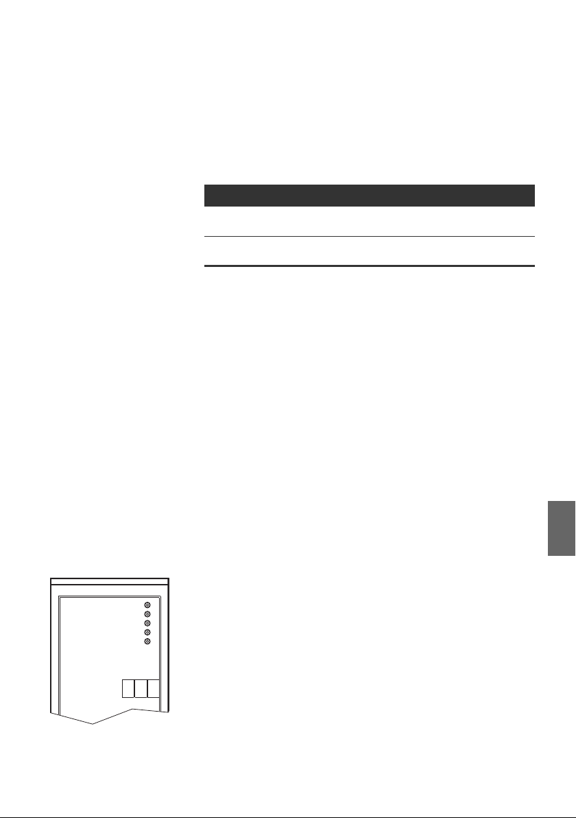
AVENTICS | DDL | R499050020–BDL–001–AD 93
Commissioning and Operation
Within the DDL line, each DDL participant’s plug connection and
the cable length lower the voltage. The bus coupler works with
an operating voltage of 24 V DC and has been designed for the
following tolerance ranges.
Table 22: Thresholds of the supply voltages
Voltage at X72 U
Electronic voltage
Sensor voltage
Valve voltage
UV 1-4, UV 5-8, UV 9-12
[V] U
min
19.2 28.8
21.6 26.4
max
[V]
No DDL communication Possible causes for a display of missing DDL communication
are:
W Baud rate set for the bus coupler is not the same.
W There are gaps in the addressing.
W The same address was assigned to 2 modules.
W Address 0 and 1 to 14 have been assigned simultaneously.
W The configuration was changed during operation.
W The configuration of the inserted modules is incorrect.
W The maximum number of 3 input and 3 output modules has
been exceeded.
W 4 bytes length of the output data has been exceeded.
W Problem with the internal data communication
(e.g. defective modules).
W Incorrect initialization
English
RMV04-DDL
SENSOR
UV 1-4
UV 5-8
UV 9-12
DDL
BTN
7.3.2 Overload protection
The sensor supply comes from the DDL “sensor” voltage. If the
sensor power supply has a short-circuit at a socket or exceeds
the total voltage of 0.5 A for all sockets, then the short-circuit
protection is triggered. The green SENSOR LED will flash.
If the sensor supply is overloaded, the voltage will be disrupted at
all plugs until the malfunction has been remedied. This
malfunction is not stored, the unit will automatically go back into
a normal operating state.

94 AVENTICS | DDL | R499050020–BDL–001–AD
Commissioning and Operation
7.3.3 Software diagnosis
The software in the controller monitors the connected VS. To do
this, the bus coupler transfers the diagnostic data to the
superior bus system and provides it to the controller.
Diagnostic data of the VS The diagnostic data of the valve system is located in the
diagnostic data section in accordance with the DDL address. If
the address 0 (automatic addressing) is set, the VS will act like
a valve unit. The VS will act like a combination module if it has
input modules.
The length of the diagnosis area is 1 byte plus the set output
data length in bytes (see “Setting the output data length for
valves” on page 88).
The diagnostic data is made up of three parts:
W The first byte (Z) is the standard diagnosis.
W The second part is made up of up to 4 bytes of output
diagnostic data (Z + 1 to Z + 4), according to the expansion
stage.
W The third part (Z + 5) is made up of the module diagnostic
data. The module diagnostic data is only transferred if
modules are connected.
Output modules send a diagnosis bit if there is a short
circuit. This is prepared in input modules, but is not yet
active.

AVENTICS | DDL | R499050020–BDL–001–AD 95
Commissioning and Operation
Table 23: Assignment of the diagnosis bits
Byte Bit 7 Bit 6 Bit 5 Bit 4 Bit 3 Bit 2 Bit 1 Bit 0
Z DDL
communi-
cation
Z +1 Valve 4
Solenoid 12
Z + 2 Valve 8
Solenoid 12
Z + 3 Valve 12
Solenoid 12
Z + 4 Valve 16
Solenoid 12
Z + 5 –
––
Valve 4
Solenoid 14
Valve 8
Solenoid 14
Valve 12
Solenoid 14
Valve 16
Solenoid 14
Valve 3
Solenoid 12
Valve 7
Solenoid 12
Valve 11
Solenoid 12
Valve 15
Solenoid 12
– Module 6 Module 5 Module 4 Module 3 Module 2 Module 1
Table 24: Assignment of the diagnosis bits
Byte Bit Meaning
Z + 1 to
Z + 4
1)
See Tab. 22 on page 93 for the supply voltage thresholds.
2)
Device is defective.
Internal
error
Valve 3
Solenoid 14
Valve 7
Solenoid 14
Valve 11
Solenoid 14
Valve 15
Solenoid 14
24 V
UV 9-12
Valve 2
Solenoid 12
Valve 6
Solenoid 12
Valve 10
Solenoid 12
Valve 14
Solenoid 12
24 V
UV 5-8
Valve 2
Solenoid 14
Valve 6
Solenoid 14
Valve 10
Solenoid 14
Valve 14
Solenoid 14
Z 0 24 V electronic voltage
1 24 V UV 1 – 4
2 24 V UV 5 – 8
3 24 V UV 9 – 12
4 Internal error
1)
1)
1)
2)
5–
6–
7 DDL communication diagnosis
0 to 7 Short circuit at output or open load
(see “Parameters”)
24 V
UV 1-4
Valve 1
Solenoid 12
Valve 5
Solenoid 12
Valve 9
Solenoid 12
Valve 13
Solenoid 12
1)
24 V
Electronic
voltage
Valve 1
Solenoid 14
Valve 5
Solenoid 14
Valve 9
Solenoid 14
Valve 13
Solenoid 14
English
Recognizing a short
circuit or open load
Byte Z is the start address of the diagnosis area for this DDL
participant in the controller.
The bus coupler can recognize if there is a short circuit or open
load in a valve solenoid. The diagnostic data is not different. A
short circuit may occur if e.g. the isolation of the valve solenoid
has been damaged. An open load may occur if e.g. the valve
solenoid in a valve has blown or if a contact has been
interrupted.

96 AVENTICS | DDL | R499050020–BDL–001–AD
Commissioning and Operation
A short circuit can only be recognized if the valve output is
controlled.
An off valve output can only be recognized if it is not
controlled.
O Exchange the defective valve if the diagnostic data reports a
short circuit or open load.
Parameters These functions are made available to the bus coupler by the
valve system. The parameter bytes may be used depending on
the fieldbus system. The valve system provides the bus coupler
with 1 parameter byte.
Table 25: Parameters for the valve system
Bit Parameter name Bit = 0 Bit = 1
7 Reserved – –
6 Reserved – –
5 Reserved – –
4 Reserved – –
3 Reaction with DDL
failure
2 Reserved – –
1 Solenoid diagnostic
message
0 Reserved – –
Values at 0
(default)
With controlled
outputs (default)
Freeze values
Changes are being
transferred
W Bit 1 = 0: Only send an output diagnostic message if the
output is being controlled. A check is not done to see which
solenoids are available when the system is switched on. If
an output is being controlled where there is no solenoid, a
diagnostic message will be generated.
W Bit 1 = 1: A check is done once to see which solenoids are
available when the system is switched on. This information
is transferred to the controller via a diagnostic message.
This message can be compared with a stored system
configuration in the controller. (This function is only
supported with Profibus DP, the diagnostic data is cyclically
transferred in other fieldbus systems.)

AVENTICS | DDL | R499050020–BDL–001–AD 97
Commissioning and Operation
Missing solenoids can be determined when the system is
switched on. In cyclical operation, diagnostic messages are
only sent if there have been any changes. “Open load” is
reported immediately and the valve does not have to be
controlled.
W Bit 3 = 0: If the bus coupler malfunctions, the output data in
the valve system will be set to 0.
W Bit 3 = 1: If the bus coupler malfunctions, the output data in
the valve system will be stored and the solenoids will
continue to be controlled (freeze values).
Changed parameters only become effective when the
device is switched off and then on again or if it is initialized.
7.3.4 Check sensors on the input module
There is one LED per input on the input module for monitoring
purposes. The LED lights up if the signal level is “high”.
O Before commissioning the system, check the sensor
function and method of operation by reading the LEDs.
Fig. 8: LED displays on the M8 input module (left) and M12 (right)
Table 26: LED display on the input modules
LED Color Meaning
Input Yellow High signal level mode
English

98 AVENTICS | DDL | R499050020–BDL–001–AD
O
O
O
O
O
O
O
O
OO
Commissioning and Operation
7.3.5 Check actuators on the output module
O Before commissioning, check the actuator function and the
method of operation using the LED displays on the output
module (see Tab. 27).
Fig. 9: LED displays on the M8 output module (left) and M12 (right)
Table 27: Meaning of the LED display on the output module
LED Color Meaning
UQ1 Green Load supply UQ1 available
Red Diagnosis: Overload/short circuit of controlled
Off Load supply U
UQ2 Green Load supply UQ2 available
Red Diagnosis: Overload/short circuit of controlled
Off Load supply UQ2 not available
O0 to O7 Off Corresponding LOW level output
Yellow Corresponding HIGH level output
output O0, O1, O2, or O3
not available
(e.g. emergency OFF)
Q1
output O4, O5, O6, or O7
(e.g. emergency OFF)

AVENTICS | DDL | R499050020–BDL–001–AD 99
Commissioning and Operation
7.4 Commissioning the bus coupler
Before commissioning the system, the following steps must
have been carried out and completed:
W You have assembled the valve terminals and the bus coupler
(see “Assembling the valve system with the bus coupler” on
page 75).
W You have connected the bus coupler (see “Connecting the
modules electrically” on page 77).
W You have made presettings and configured the system
(see “Making presettings” on page 85).
W You have configured the bus master so that it controls the
valves and the input modules correctly.
Commissioning and operation may only be carried out by
qualified electrical or pneumatic personnel or an instructed
person under the direction and supervision of qualified
personnel (see also “Personnel qualifications” on page 65).
CAUTION
Uncontrolled actuator movements when the pneumatics are
switched on
Danger of injury if the system is in an undefined state or the
manual overrides are set to position “1”.
O Put the system in a defined state before switching it on.
O Set all manual overrides to position “0”.
O Make sure that no personnel are within the hazardous zone
when the pressure is switched on.
O Also observe the applicable instructions and safety
information in the VS operating instructions.
1. Switch on the operating voltage.
2. Check the LED displays on all modules.
3. Switch on the compressed air supply.
English

100 AVENTICS | DDL | R499050020–BDL–001–AD
Disassembly and Exchange
8 Disassembly and Exchange
You can either exchange the bus coupler or connect additional/
other input/output modules as needed.
The AVENTICS warranty only applies to the delivered
configuration and extensions taken into account in the
configuration. The warranty no longer applies after a
conversion that exceeds these extensions.
8.1 Exchanging the bus coupler
Applied voltage and high pressure!
Danger of injury from electric shocks and sudden pressure
drops.
O Make sure the system is not under pressure or voltage
before you exchange the modules.
CAUTION
 Loading...