

AVENTICS Instrucciones de servicio: Sensor de medición de caudal IO-Link , Serie AF2, Flow rate sensor IO-Link , Series AF2, Notice d’instruction: Capteur de débit IO-Link , Série AF2, Betriebsanleitung: Durchflusssensor IO-Link , Serie AF2, Istruzioni per l'uso: Flussometro IO-Link , Serie AF2 Manuals & Guides [fr]
...Page 1
Betriebsanleitung | Operating instructions | Notice d’instruction
Istruzioni per l'uso | Instrucciones de servicio | Bruksanvisning
AVENTICS™ IO-Link AF2
Durchflusssensor
Flow rate sensor
Capteur de débit
Flussometro
Sensor de medición de caudal
Flödessensor
R412027828-BAL-001-AA
2020-03, Replaces: -
DE/EN/FR/IT/ES/SV
Page 2

Inhaltsverzeichnis
1 Durchflusssensor im IO-Link-System konfigurieren...................................................................................................................................................................... 3
2 Physikalische Schicht ................................................................................................................................................................................................................... 3
3 Prozessdaten ............................................................................................................................................................................................................................... 3
4 Servicedaten................................................................................................................................................................................................................................ 3
AVENTICS™ IO-Link AF2 | R412027828-BAL-001-AA | Deutsch 2
Page 3

1 Durchflusssensor im IO-Link-System konfigurieren
Die IODD-Dateien und die Technischen Informationen mit englischen
und deutschen Texten für den Durchflusssensor IO-Link finden Sie im
Media Centre.
Zur IO-Link-Konfiguration können Sie Konfigurationsprogramme verschiedener
Hersteller einsetzen.
Bevor Sie den Durchflusssensor nutzen können, muss dieser vom IO-Link-Master
erkannt werden. Dies geschieht entweder automatisch oder muss manuell ausgeführt werden.
u Beachten Sie dazu die Dokumentation des verwendeten IO-Link-Masters.
2 Physikalische Schicht
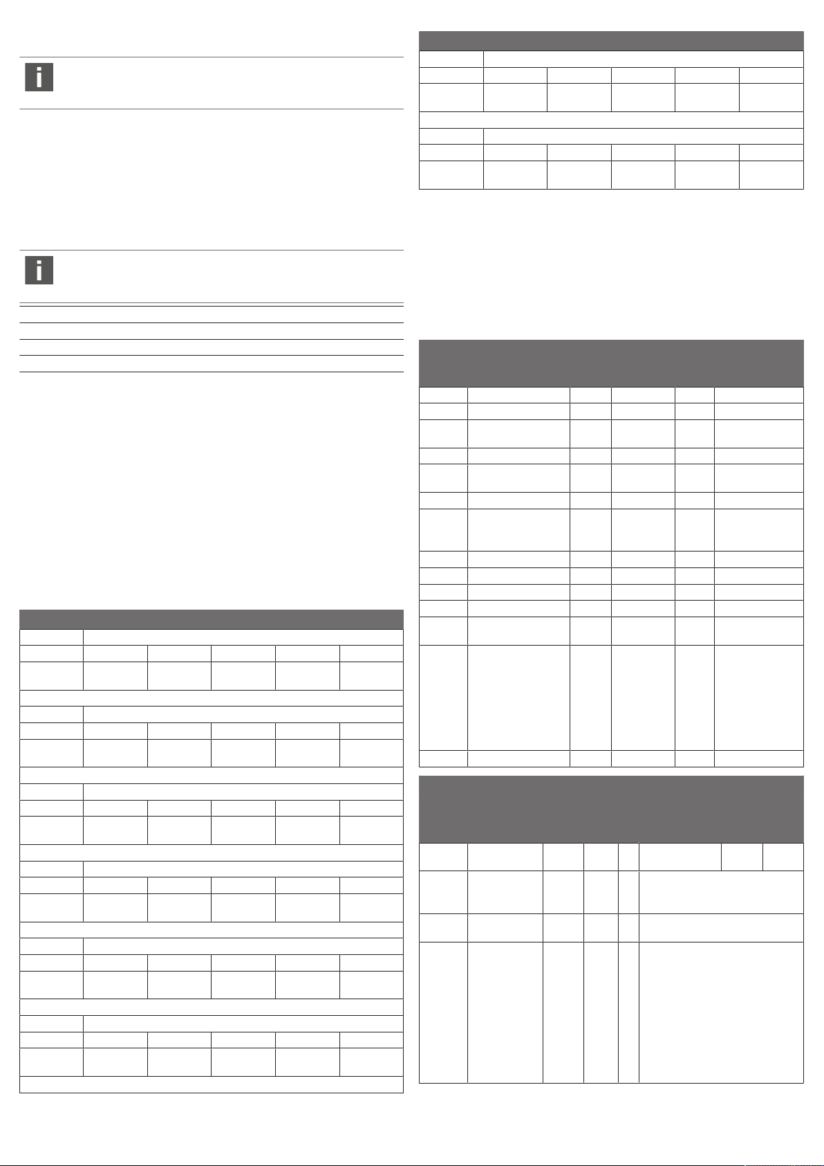
Record: 32 Byte – Prozessdaten
Type/Subindex
Bitoffset
Byte/Name
Type/Subin-
dex
Bitoffset
Byte/Name
Type/Subin-
dex
24 25 26 Temperatur 27
28 29 30 Druck 31
Float 3
32
Float 2
0
Float 1
Die maximale Stromaufnahme des IO-Link Devices (inkl. Lastströme)
darf den maximalen Ausgangsstrom des Master-Ports nicht überschreiten.
SIO Modus ja
Min. Zykluszeit 3,0 ms
Baudrate COM3
Prozessdatenlänge (IN) 32 Byte
COM-Werte spezifizieren die Baudrate (s. IO-Link-Spezifikation): COM3 (230,4
kbit/s)
3 Prozessdaten
Massendurchfluss [kg/h]
Durchflussgeschwindigkeit [m/s]
Volumen [m³]
Volumendurchfluss [m³/h]
Masse [kg]
Energie [kWh]
Temperatur [°C]
Druck [bar]
Record: 32 Byte – Prozessdaten
Bitoffset
Byte/Name
Type/Subindex
Bitoffset
Byte/Name
Type/Subindex
Bitoffset
Byte/Name
Type/Subin-
dex
0 1 2 Massendurch-
fluss
Float 8
4 5 6 Durchflussge-
schwindigkeit
Float 7
8 9 10 Volumen 11
Float 6
3
7
4 Servicedaten
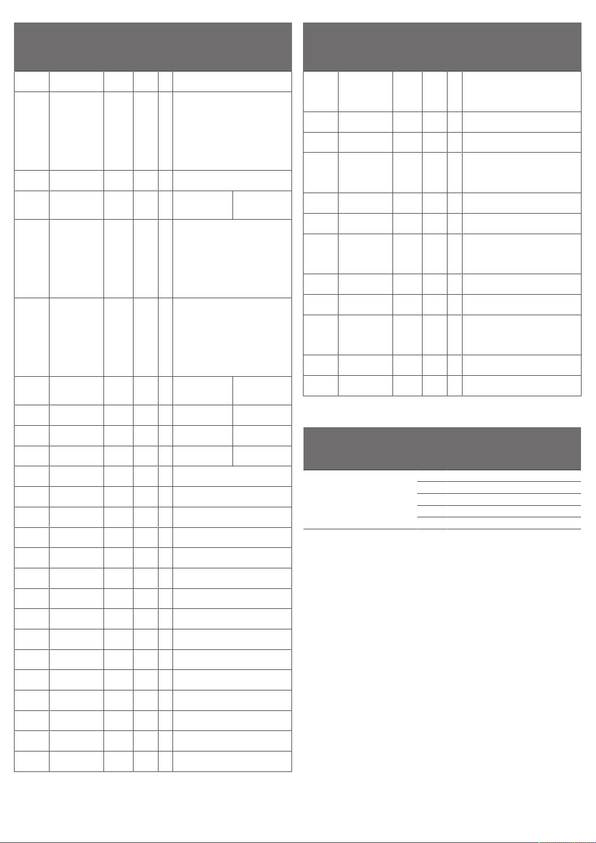
Die folgenden ISDUs werden nicht über Data-Storage gesichert: Direkte Parameter 1, Direkte Parameter 2, Sensorspezifischer Name, Q1 Simulation Schaltausgang, Q2 Schaltausgang Simulation, Q2 Frequenz Simulation, Qa Analogwert Simulation, Q2, Analogwert Simulation, Simulation Durchfluss, Simulation Temperatur, Simulation Druck und Sonderfunktion Speicher.
IO-Link spezifisch
Index
dez
(hex)
Name
12 (0x0C) Gerätezugriffssperre Record 2 Byte rw
2 (0x02) Datenspeicherungs-
4 (0x04) Lokale Benutzerinter-
16 (0x10) Herstellername String 64 Byte ro Aventics
17 (0x11) Herstellertext String 64 Byte ro Emerson – Consider
18 (0x12) Produktname String 64 Byte ro AF2
19 (0x13) Produkt-ID String 64 Byte ro R412026761
20 (0x14) Produkttext String 64 Byte ro Air Flow Sensor
224
21 (0x15) Seriennummer String 16 Byte ro
22 (0x16) Hardwareversion String 64 Byte ro
23 (0x17) Firmwareversion String 64 Byte ro
24 (0x18) Anwendungsspezifi-
36 (0x24) Gerätestatus UInt 8 Bit ro 0 = Gerät ist OK
192
160
40 (0x28) Prozessdaten Eingang PD In 32 Byte ro
sperre
face-Sperre
sche Markierung
Format
(Offset)
Länge
Bit (1) 1 Bit rw
Bit (3) 1 Bit rw
String 32 Byte rw ***
Zugriff
It Solved
R412026762
R412026763
1 = Wartung erforderlich
2 = Außerhalb der
Spezifikation
3 = Funktionsprüfung
4 = Fehler
5...255 = reserviert
Standard-
wert
Bitoffset
Byte/Name
Type/Subindex
Bitoffset
Byte/Name
Type/Subin-
dex
Bitoffset
Byte/Name
12 13 14 Volumen-
durchfluss
Float 5
16 17 18 Masse 19
Float 4
20 21 22 Energie 23
15
AVENTICS spezifisch
128
Index dez
(hex)
Name
64 (0x40) Sensorspezifi-
96
66 (0x42) Systemstatus UInt 8 Bit ro 0 = Ok
190
(0xBE)
64
scher Name
OpTimer UInt 32 Bit ro Betriebszeit in Sekunden [s]
Format
(Offset)
String 32
Byte
Länge
Zugriff
Standard-
wert
rw ***
1 = Warnung vor Fehler
2 = Fehler
Wertebereich
Bemerkung
[Einheit]
AVENTICS™ IO-Link AF2 | R412027828-BAL-001-AA | Deutsch 3
Page 4

AVENTICS spezifisch
Index dez
(hex)
Name
260
(0x104)
262
(0x106)
270
(0x10E)
271
(0x10F)
272
(0x110)
278
(0x116)
279
(0x117)
291
(0x123)
292
(0x124)
299
(0x12B)
300
(0x12C)
301
(0x12D)
302
(0x12E)
307
(0x133)
308
(0x134)
309
(0x135)
310
(0x136)
311
(0x137)
312
(0x138)
313
(0x139)
314
(0x13A)
Q1 Modus UInt 8 Bit rw
Q1 Typ UInt 8 Bit rw 2 = NPN
Q1 Schaltpunkt
1 setzen
Q1 Schaltpunkt
2 setzen
Q1 Einheit und
Bereich
Q1 Polarität UInt 8 Bit rw 0 = Schließer
Q1 Simulation
Schaltausgang
Q2 Funktion UInt 8 Bit rw 0 0 = Schaltausgang
Q2 Typ UInt 8 Bit rw 2 = NPN
Q2 Schalt-Modus
Q2 Schaltpunkt
1 setzen
Q2 Schaltpunkt
2 setzen
Q2 Schaltausgang Einheit und
Bereich
Q2 Schaltausgang Simulation
Q2 Schaltausgang Polarität
Qa Pulsausgang
Einheit und
Bereich
Q2 Pulswertigkeit
Q2 Pulsbreite UInt 32 Bit rw 1...2000 [ms]
Q2 Pulsmodus UInt 8 Bit rw 0 = Volumen
Q2 oberer Frequenzwert
Q2 unterer Frequenzwert
Format (Off-
set)
Länge
Zugriff
Standard-
wert
0 = Schaltausgang-HystereseVolumendurchfluss
1 = Schaltausgang-FensterfunktionVolumendurchfluss
2 = Schaltausgang-Hysterese-Druck
3 = Schaltausgang-FensterfunktionDruck
4 = Schaltausgang-HystereseTemperatur
5 = Schaltausgang-FensterfunktionTemperatur
3 = PNP
4 = DRV/Push-Pull
Float 4 Byte rw - 30.0...999
Float 4 Byte rw - 30.0...999
String 32
Byte
UInt 8 Bit rw 255 0 = inaktiv
UInt 8 Bit rw 0 = Schaltausgang-Hysterese-Volu-
Float 4 Byte rw - 30.0...999
Float 4 Byte rw - 30.0...999
String 32
Byte
UInt 8 Bit rw 255 0 = inaktiv
UInt 8 Bit rw 0 = Schließer
String 32
Byte
Float 4 Byte rw 0.001...10
Float 4 Byte rw -30.0...999
Float 4 Byte rw - 30.0...999
9.0
9.0
ro Einheit und Bereich für Index 270
und 271
1 = Öffner
3 = PNP
4 = DRV/Push- Pull
mendurchfluss
1 = Schaltausgang-Fensterfunktion-
Volumendurchfluss
2 = Schaltausgang-Hysterese-Druck
3 = Schaltausgang-Fensterfunktion-
Druck
4 = Schaltausgang-Hysterese-Tem-
peratur
5 = Schaltausgang-Fensterfunktion-
Temperatur
9.0
9.0
ro Einheit und Bereich für Index 300
und 301
1 = Öffner
ro Einheit und Bereich für Index 310
0.0
1 = Energie
9.0
9.0
Wertebereich
Bemerkung
siehe Index 272
siehe Index 272
1 = aktiv
255 = normal
1 = Frequenz
2 = Pulsausgang
3 = Analogaus-
gang
für Schalt-, Puls-
und Frequenzausgang
siehe Index 302
siehe Index 302
1 = aktiv
255 = normal
siehe Index 309
siehe Index 315
siehe Index 315
AVENTICS spezifisch
[Einheit]
315
(0x13B)
316
(0x13C)
317
(0x13D)
318
(0x13E)
319
(0x13F)
380
(0x17C)
383
(0x17F)
384
(0x180)
385
(0x181)
386
(0x182)
390
(0x186)
391
(0x187)
400
(0x190)
403
(0x193)
404
(0x194)
405
(0x195)
406
(0x196)
410
(0x19A)
411
(0x19B)
420
(0x1A4)
Index dez
(hex)
Name
Q2 Frequenz Einheit und Bereich
Q2 maximale
Frequenz
Q2 minimale
Frequenz
Q2 Frequenz Simulation
Q2 FrequenzModus
Qa AnalogModus
Qa Analog-Pola-
rität
Qa oberer Analogwert (20mA)
Qa unterer Analogwert (4mA)
Qa Analogsignal
Einheit und Bereich
Qa Analogsignal
im Fehlerfall
Qa Analogwert
Simulation
Q2 Analogmodus
Q2 Analog-Polarität
Q2 oberer Analogwert (20mA)
Q2 unterer Analogwert (4mA)
Q2 Analogsignal
Einheit und Bereich
Q2 Analogwert
im Fehlerfall
Q2 Analogwert
Simulation
Anzeige Einheit
Massendurchfluss
Format (Off-
set)
Länge
Zugriff
Standard-
wert
String 32
UInt 16 Bit rw 0...10000 [Hz]
UInt 16 Bit rw 0...10000 [Hz]
UInt 8 Bit rw 255 0 = 1Hz
UInt 8 Bit rw 0 = Volumendurchfluss
UInt 8 Bit rw 0 = 4-20mA Volumendurchfluss
UInt 8 Bit rw 0 = Normal
Float 4 Byte rw - 30.0...999
Float 4 Byte rw - 30.0...999
String 32
UInt 8 Bit rw 0 = 3.5mA
UInt 8 Bit rw 255 35 = 3.5mA
UInt 8 Bit rw 0 = 4-20mA Volumendurchfluss
UInt 8 Bit rw 0 = Normal
Float 4 Byte rw - 30.0...999
Float 4 Byte rw - 30.0...999
String 32
UInt 8 Bit rw 0 = 3.5mA
UInt 8 Bit rw 255 35 = 3.5mA
UInt 8 Bit rw 0 = kg/h
ro Einheit und Bereich für Index 313
Byte
Byte
Byte
und 314
1 = 4-20mA Druck
2 = 4-20mA Temperatur
1 = Invertiertes Signal
9.0
9.0
ro Einheit und Bereich für Index 384
und 385
1 = 21.5mA
1 = 4-20mA Druck
2 = 4-20mA Temperatur
1 = Invertiertes Signal
9.0
9.0
ro Einheit und Bereich für Index 404
und 405
1 = 21.5mA
1 = g/s
2 = kg/min
Wertebereich
1 = 10Hz
2 = 100Hz
3 = 1kHz
4 = 10kHz
255 = Simulation
aus
siehe Index 386
siehe Index 386
38 = 3.8mA
40 = 4.0mA
100 = 10mA
120 = 12mA
180 = 18mA
200 = 20mA
205 = 20,5mA
215 = 21,5mA
255 = Simulation
aus
siehe Index 406
siehe Index 406
38 = 3.8mA
40 = 4.0mA
100 = 10mA
120 = 12mA
180 = 18mA
200 = 20mA
205 = 20,5mA
215 = 21,5mA
255 = Simulation
aus
Bemerkung
[Einheit]
AVENTICS™ IO-Link AF2 | R412027828-BAL-001-AA | Deutsch 4
Page 5

AVENTICS spezifisch
Index dez
(hex)
Name
421
(0x1A5)
422
(0x1A6)
423
(0x1A7)
424
(0x1A8)
425
(0x1A9)
426
(0x1AA)
427
(0x1AB)
428
(0x1AC)
429
(0x1AD)
430
(0x1AE)
431
(0x1AF)
432
(0x1B0)
433
(0x1B1)
434
(0x1B2)
435
(0x1B3)
Anzeige Einheit
Gasgeschwindigkeit
Anzeige Einheit
Volumen
Anzeige Einheit
Volumendurchfluss
Anzeige Einheit
Masse
Anzeige Einheit
Energie
Anzeige Einheit
Temperatur
Anzeige Einheit
Druck
Anzeige ausschalten
Anzeige drehen UInt 8 Bit rw 0 = 0°
Anzeigenschoner
Anzeige Helligkeit
Anzeige Pin UInt 16 Bit rw 0...9999 Pin zum Schutz
Anzeige 1 oben UInt 8 Bit rw 0 = Massendurchfluss
Anzeige 1 unten UInt 8 Bit rw 0 = Massendurchfluss
Anzeige 2 oben UInt 8 Bit rw 0 = Massendurchfluss
Format
(Offset)
Länge
Zugriff
Standard-
wert
UInt 8 Bit rw 0 = m/s
UInt 8 Bit rw 0 = m³
UInt 8 Bit rw 0 = m³/h
UInt 8 Bit rw 0 = kg
UInt 8 Bit rw 0 = kWh
UInt 8 Bit rw 0 = °C
UInt 8 Bit rw 0 = bar
UInt 8 Bit rw 0 = Aus
UInt 8 Bit rw 0 = Aus
UInt 8 Bit rw 2 = 40%
1 = fps
1 = l
2 = ft³
1 = m³/min
2 = l/s
3 = l/min
4 = ft³/s
5 = ft³/min
1 = °F
1 = psi
1 = 1min
2 = 2min
5 = 5min
10 = 10min
30 = 30min
60 = 60min
1 = 90°
2 = 180°
3 = 270°
1 = 1min
2 = 2min
5 = 5min
10 = 10min
30 = 30min
60 = 60min
7 = 60%
10 = 80%
15 = 100%
1 = Durchflussgeschwindigkeit
2 = Volumen
3 = Volumendurchfluss
4 = Masse
5 = Energie
6 = Temperatur
7 = Druck
1 = Durchflussgeschwindigkeit
2 = Volumen
3 = Volumendurchfluss
4 = Masse
5 = Energie
6 = Temperatur
7 = Druck
1 = Durchflussgeschwindigkeit
2 = Volumen
3 = Volumendurchfluss
4 = Masse
5 = Energie
6 = Temperatur
7 = Druck
Wertebereich
Bemerkung
[Einheit]
der Konfiguration,
0000 ==> kein Pin
vergeben
AVENTICS spezifisch
Index dez
(hex)
Name
436
(0x1B4)
437
(0x1B5)
438
(0x1B6)
439
(0x1B7)
440
(0x1B8)
441
(0x1B9)
442
(0x1BA)
Anzeige 2 unten UInt 8 Bit rw 0 = Massendurchfluss
Anzeige 3 oben UInt 8 Bit rw 0 = Massendurchfluss
Anzeige 3 unten UInt 8 Bit rw 0 = Massendurchfluss
Anzeige Historie UInt 8 Bit rw 0 = Massendurchfluss
Simulation
Durchfluss
Simulation Temperatur
Simulation
Druck
Format
(Offset)
Länge
Zugriff
Standard-
1 = Durchflussgeschwindigkeit
2 = Volumen
3 = Volumendurchfluss
4 = Masse
5 = Energie
6 = Temperatur
7 = Druck
1 = Durchflussgeschwindigkeit
2 = Volumen
3 = Volumendurchfluss
4 = Masse
5 = Energie
6 = Temperatur
7 = Druck
1 = Durchflussgeschwindigkeit
2 = Volumen
3 = Volumendurchfluss
4 = Masse
5 = Energie
6 = Temperatur
7 = Druck
1 = Durchflussgeschwindigkeit
2 = Volumen
3 = Volumendurchfluss
4 = Masse
5 = Energie
6 = Temperatur
7 = Druck
UInt 8 Bit rw 0 = 0%
UInt 8 Bit rw 0 = 0%
UInt 8 Bit rw 0 = 0%
10 = 10%
20 = 20%
30 = 30%
40 = 40%
50 = 50%
60 = 60%
70 = 70%
80 = 80%
90 = 90%
100 = 100%
255 = Simulation Aus
10 = 10%
20 = 20%
30 = 30%
40 = 40%
50 = 50%
60 = 60%
70 = 70%
80 = 80%
90 = 90%
100 = 100%
255 = Simulation Aus
10 = 10%
20 = 20%
30 = 30%
40 = 40%
50 = 50%
60 = 60%
70 = 70%
80 = 80%
90 = 90%
100 = 100%
255 = Simulation Aus
wert
Wertebereich
Bemerkung
[Einheit]
AVENTICS™ IO-Link AF2 | R412027828-BAL-001-AA | Deutsch 5
Page 6

AVENTICS spezifisch
Index dez
(hex)
Name
443
(0x1BB)
444
(0x1BC)
445
(0x1BD)
446
(0x1-BE)
447
(0x1BF)
448
(0x1C0)
449
(0x1C1)
450
(0x1C2)
453
(0x1C5)
454
(0x1C6)
458
(0x1CA)
481
(0x1E1)
482
(0x1E2)
483
(0x1E3)
484
(0x1E4)
485
(0x1E5)
486
(0x1E6)
487
(0x1E7)
Durchflussmedium
Referenzkonditionen für
den Durchfluss
Kundenspezifischer Referenzdruck
Kundenspezifische
Referenztemperatur
Eingabe
Nullpunktversatz
für Durchfluss
Eingabe
Schleichmengenunterdrückung
Eingabe Glättungsfilter für
Durchfluss
DurchflussMessmodus
Eingabe Nullpunktversatz für
Druck
Eingabe Glättungsfilter für
Druck
Eingabe Glättungsfilter für
Temperatur
Signalqualität 1
(Sensorrobustheit)
Signalqualität 2 UInt 8 Bit ro 0...100 [%]
Signalqualität 3 UInt 8 Bit ro 0...100 [%]
Signalqualität 4 UInt 8 Bit ro 0...100 [%]
PowerUp Zähler UInt 32 Bit ro
Spannungsversorgung Sensor
Sensor Temperatur
Format
(Offset)
Länge
Zugriff
Standard-
wert
UInt 8 Bit rw 0 = Luft
1 = Nitrogen
2 = Kohlendioxid CO2
3 = Helium
4 = Argon
UInt 8 Bit rw 0 = ISO8778
1 = ISO6358
2 = DIN1343
3 = DIN1945-1
4 = ISO1217
5 = ISO2533
6 = kundenspezifisch
Float 4 Byte rw -1.0...16.0
Float 4 Byte rw -20.0...60.0
Float 4 Byte rw -10.0...10.0
Float 4 Byte rw 0.0...10.0
UInt 8 Bit rw 0 = Aus
1 = 100ms
2 = 200ms
5 = 500ms
10 = 1sec
20 = 2sec
50 = 5sec
100 = 10sec
UInt 8 Bit rw 0 = Standard
Float 4 Byte rw -0.5...0.5 [bar]
UInt 8 Bit rw 0 = Aus
1 = 100ms
2 = 200ms
5 = 500ms
10 = 1sec
20 = 2sec
50 = 5sec
100 = 10sec
UInt 8 Bit rw 0 = Aus
1 = 100ms
2 = 200ms
5 = 500ms
10 = 1sec
20 = 2sec
50 = 5sec
100 = 10sec
UInt 8 Bit ro 0...100 [%]
Float 4 Byte ro [V]
Float 4 Byte ro (Parameter in 0.1°C) [°C]
Wertebereich
Bemerkung
[Einheit]
AVENTICS spezifisch
Index dez
(hex)
Name
488
(0x1E8)
1 (0x01) Minimal Bit (64) 4 Byte ro
2 (0x02) Maximal Bit (32) 4 Byte ro
3 (0x03) Durchschnittli-
489
(0x1E9)
490
(0x1EA)
491
(0x1EB)
492
(0x1EC)
493
(0x1ED)
496
(0x1F0)
502
(0x1F6)
1 (0x01)
2 (0x02) Meldung 1 Level Bit
3 (0x03) Meldung 1 Be-
4 (0x04) Meldung 2 Num-
5 (0x05) Meldung 2 Level Bit (816) 8 Bit ro 0 = keine Meldung
6 (0x06) Meldung 2 Be-
7 (0x07)
8 (0x08) Meldung 3 Level Bit (536) 8 Bit ro 0 = keine Meldung
9 (0x09) Meldung 3 Be-
10 (0x0A) Bit (264) 16 Bit ro
11 (0x0B) Meldung 4 Level Bit (256) 8 Bit ro 0 = keine Meldung
12 (0x0C) Meldung 4 Be-
17342
(0x43BE)
Statistik Massendurchfluss
cher Wert
Statistik
Durchflussgeschwindigkeit
Statistik Volumendurchfluss
Statistik Temperatur
Statistik Druck Record 12
Statistikdauer
seit Reset
Zählerstand seit
Reset
aktive
Meldungen
Meldung 1
Nummer
schreibung
mer
schreibung
Meldung 3
Nummer
schreibung
Meldung 4
Nummer
schreibung
Hardware
Identifikationsschlüssel
Format
(Offset)
Länge
Zugriff
Standard-
wert
Record 12
Bit (0) 4 Byte ro
Record 12
Record 12
Record 12
UInt 32 Bit ro siehe Index 488
UInt 32 Bit ro Reset Prozessdaten rVolume, rMass,
Record 140
Bit
(1104)
(1096)
Bit (840) 32
Bit (824) 16 Bit ro
Bit (560) 32
Bit (544) 16 Bit ro
Bit (280) 32
Bit (0) 32
String 32
ro
Byte
ro siehe Index 488
Byte
ro siehe Index 488
Byte
ro siehe Index 488
Byte
ro siehe Index 488
Byte
rEnergy
ro 4 aktive Meldungen mit höchster
Byte
16 Bit ro
8 Bit ro 0 = keine Meldung
Byte
Byte
Byte
Byte
Byte
Priorität
1 = Information
2 = Warnung
3 = Fehler
ro
1 = Information
2 = Warnung
3 = Fehler
ro
1 = Information
2 = Warnung
3 = Fehler
ro
1 = Information
2 = Warnung
3 = Fehler
ro
ro
ro = nur lesen, rw = lesen / schreiben
Wertebereich
Bemerkung
[Einheit]
AVENTICS™ IO-Link AF2 | R412027828-BAL-001-AA | Deutsch 6
Page 7

Standardkommando
Index dez
(hex)
2 (0x02) Standard-
kommando
wo = nur schreiben
Zugriff
Wert
wo 83 BM_ACTIVATE
128 Gerät zurücksetzen
130
210 Reset aller Statistikwerte
211 Reset aller Zählerwerte
Name
Auslieferungszustand
wiederherstellen
Bemerkung
[Einheit]
AVENTICS™ IO-Link AF2 | R412027828-BAL-001-AA | Deutsch 7
Page 8

Contents
1 Configuring the flow sensor in the IO-Link system........................................................................................................................................................................ 9
2 Physical layer ............................................................................................................................................................................................................................... 9
3 Process data ................................................................................................................................................................................................................................ 9
4 Service data ................................................................................................................................................................................................................................. 9
AVENTICS™ IO-Link AF2 | R412027828-BAL-001-AA | English 8
Page 9
1 Configuring the flow sensor in the IO-Link system
The IODD files and the Technical Information with English and German
language content for the flow sensor IO-Link can be found in the Media
Center.
You can use configuration software from various manufacturers for the IO-Link
configuration.
Before you can use the flow sensor, it has to be recognized by the IO-Link master.
This process is either automatic or must be completed manually.
u Please observe the documentation for the IO-Link master used.
Record: 32 Byte – process data
Bitoffset
Byte/Name
Type/
Subindex
Bitoffset
Byte/Name
Type/
Subindex
24 25 26 Temperature 27
28 29 30 Pressure 31
32
Float 2
0
Float 1
2 Physical layer
The maximum current consumption of the IO-Link device (including
load currents) must not exceed the maximum output current of the
master port.
SIO mode Yes
Min. cycle time 3.0 msec
Baud rate COM3
Process data length (IN) 32 bytes
COM values specify the Baud rate (see IO-Link specifications): COM3 (230.4 kbit/s)
3 Process data
Mass flow [kg/h]
Flow speed [m/s]
Volume [m³]
Volume flow [m³/h]
Mass [kg]
Energy [kWh]
Temperature [°C]
Pressure [bar]
Record: 32 Byte – process data
Bitoffset
Byte/Name
Type/
Subindex
Bitoffset
Byte/Name
Type/
Subindex
0 1 2 Mass flow 3
Float 8
4 5 6 Flow speed 7
Float 7
4 Service data
The following ISDUs are not backed up via data storage: Direct parameter 1, direct parameter 2, sensor-specific name, Q1 simulation switch output, Q2 switch
output simulation, Q2 frequency simulation, Qa analog value simulation, Q2,
analog value simulation, simulation flow, simulation temperature, simulation
pressure and special function memory.
IO-Link-specific
Index
dec
(hex)
Name
12 (0x0C) Device access block Record 2 bytes rw
2 (0x02) Data storage block Bit (1) 1 bits rw
4 (0x04) Local user interface
16 (0x10) Manufacturer name String 64 bytes ro AVENTICS
17 (0x11) Manufacturer text String 64 bytes ro Emerson – Consider
18 (0x12) Product name String 64 bytes ro AF2
19 (0x13) Product ID String 64 bytes ro R412026761
20 (0x14) Product text String 64 bytes ro Air flow sensor
21 (0x15) Serial number String 16 bytes ro
22 (0x16) Hardware version String 64 bytes ro
23 (0x17) Firmware version String 64 bytes ro
24 (0x18) Application-specific
224
36 (0x24) Device status UInt 8 bits ro 0 = device is OK
192
40 (0x28) Input process data PD In 32 bytes ro
block
marking
Format
(offset)
Length
Bit (3) 1 bits rw
String 32 bytes rw ***
Access
It Solved
R412026762
R412026763
1 = maintenance required
2 = outside of specification
3 = function test
4 = error
5...255 = reserved
Default
value
Bitoffset
Byte/Name
Type/
Subindex
Bitoffset
Byte/Name
Type/
Subindex
Bitoffset
Byte/Name
Type/
Subindex
Bitoffset
Byte/Name
Type/
Subindex
8 9 10 Volume 11
Float 6
12 13 14 Volume flow 15
Float 5
16 17 18 Ground 19
Float 4
20 21 22 Energy 23
Float 3
AVENTICS specific
160
Index dec
(hex)
Name
64 (0x40) Sensor-specific
128
66 (0x42) System status UInt 8 bits ro 0 = Ok
190
(0xBE)
96
260
(0x104)
64
name
OpTimer UInt 32 bits ro Operating time in seconds [s]
Q1 mode UInt 8 bits rw 0 = switch output hysteresis volume
Format
(offset)
String 32
Length
bytes
Access
Default
value
rw ***
1 = warning of error
2 = error
flow
1 = switch output window function
volume flow
2 = switch output hysteresis pressure
3 = switch output window function
pressure
4 = switch output hysteresis tempera-
ture
5 = switch output window function
temperature
Value
range
Comment
[unit]
AVENTICS™ IO-Link AF2 | R412027828-BAL-001-AA | English 9
Page 10

AVENTICS specific
Index dec
(hex)
Name
262
(0x106)
270
(0x10E)
271
(0x10F)
272
(0x110)
278
(0x116)
279
(0x117)
291
(0x123)
292
(0x124)
299
(0x12B)
300
(0x12C)
301
(0x12D)
302
(0x12E)
307
(0x133)
308
(0x134)
309
(0x135)
310
(0x136)
311
(0x137)
312
(0x138)
313
(0x139)
314
(0x13A)
315
(0x13B)
316
(0x13C)
317
(0x13D)
318
(0x13E)
Q1 type UInt 8 bits rw 2 = NPN
Q1 set switching
point 1
Q1 set switching
point 2
Q1 unit and
range
Q1 polarity UInt 8 bits rw 0 = make contact
Q1 simulation
switch output
Q2 function UInt 8 bits rw 0 0 = switch output
Q2 type UInt 8 bits rw 2 = NPN
Q2 switch mode UInt 8 bits rw 0 = switch output hysteresis volume
Q2 set switching
point 1
Q2 set switching
point 2
Q2 switch output unit and
range
Q2 switch output simulation
Q2 switch output polarity
Qa pulse output
unit and range
Q2 pulse valence Float 4
Q2 pulse width UInt 32 bits rw 1...2000 [ms]
Q2 pulse mode UInt 8 bits rw 0 = volume
Q2 upper frequency value
Q2 lower frequency value
Q2 frequency
unit and range
Q2 maximum
frequency
Q2 minimum
frequency
Q2 frequency
simulation
Format
(offset)
Length
Access
Default
value
3 = PNP
4 = DRV/push-pull
Float 4
Float 4
String 32
UInt 8 bits rw 255 0 = inactive
Float 4
Float 4
String 32
UInt 8 bits rw 255 0 = inactive
UInt 8 bits rw 0 = make contact
String 32
Float 4
Float 4
String 32
UInt 16 bits rw 0...10000 [Hz]
UInt 16 bits rw 0...10000 [Hz]
UInt 8 bits rw 255 0 = 1Hz
rw - 30.0...999
bytes
bytes
bytes
bytes
bytes
bytes
bytes
bytes
bytes
bytes
bytes
9.0
rw - 30.0...999
9.0
ro Unit and range for index 270 and 271
1 = break contact
3 = PNP
4 =
DRV/push-pull
flow
1 = switch output window function
volume flow
2 = switch output hysteresis pressure
3 = switch output window function
pressure
4 = switch output hysteresis tempera-
ture
5 = switch output window function
temperature
rw - 30.0...999
9.0
rw - 30.0...999
9.0
ro Unit and range for index 300 and 301
1 = break contact
ro Unit and range for index 310
rw 0.001...10
0.0
1 = energy
rw -30.0...999
9.0
rw - 30.0...999
9.0
ro Unit and range for index 313 and 314
Value
range
See index 272
See index 272
1 = active
255 = normal
1 = frequency
2 = pulse output
3 = analog output
for switch, pulse
and frequency
output
See index 302
See index 302
1 = active
255 = normal
See index 309
See index 315
See index 315
1 = 10Hz
2 = 100Hz
3 = 1kHz
4 = 10kHz
255 = simulation
off
Comment
[unit]
AVENTICS specific
Index dec
(hex)
Name
319
(0x13F)
380
(0x17C)
383
(0x17F)
384
(0x180)
385
(0x181)
386
(0x182)
390
(0x186)
391
(0x187)
400
(0x190)
403
(0x193)
404
(0x194)
405
(0x195)
406
(0x196)
410
(0x19A)
411
(0x19B)
420
(0x1A4)
421
(0x1A5)
422
(0x1A6)
423
(0x1A7)
424
(0x1A8)
425
(0x1A9)
426
(0x1AA)
Q2 frequency
mode
Qa analog mode UInt 8 bits rw 0 = 4-20mA volume flow
Qa analog
polarity
Qa upper analog
value (20mA)
Qa lower analog
value (4mA)
Qa analog signal
unit and range
Qa analog signal
in case of error
Qa analog value
simulation
Q2 analog mode UInt 8 bits rw 0 = 4-20mA volume flow
Q2 analog
polarity
Q2 upper analog
value (20mA)
Q2 lower analog
value (4mA)
Q2 analog signal
unit and range
Q2 analog value
in case of error
Q2 analog value
simulation
Display unit
mass flow
Display unit gas
speed
Display unit
volume
Display unit volume flow
Display unit
mass
Display unit energy
Display unit temperature
Format
(offset)
Length
Access
Default
value
UInt 8 bits rw 0 = volume flow
1 = 4-20mA pressure
2 = 4-20mA temperature
UInt 8 bits rw 0 = normal
Float 4
bytes
Float 4
bytes
String 32
bytes
UInt 8 bits rw 0 = 3.5mA
UInt 8 bits rw 255 35 = 3.5mA
UInt 8 bits rw 0 = normal
Float 4
bytes
Float 4
bytes
String 32
bytes
UInt 8 bits rw 0 = 3.5mA
UInt 8 bits rw 255 35 = 3.5mA
UInt 8 bits rw 0 = kg/h
UInt 8 bits rw 0 = m/s
UInt 8 bits rw 0 = m³
UInt 8 bits rw 0 = m³/h
UInt 8 bits rw 0 = kg
UInt 8 bits rw 0 = kWh
UInt 8 bits rw 0 = °C
1 = inverted signal
rw - 30.0...999
9.0
rw - 30.0...999
9.0
ro Unit and range for index 384 and 385
1 = 21.5mA
1 = 4-20mA pressure
2 = 4-20mA temperature
1 = inverted signal
rw - 30.0...999
9.0
rw - 30.0...999
9.0
ro Unit and range for index 404 and 405
1 = 21.5mA
1 = g/s
2 = kg/min
1 = fps
1 = l
2 = ft³
1 = m³/min
2 = l/s
3 = l/min
4 = ft³/s
5 = ft³/min
1 = °F
Value
range
See index 386
See index 386
38 = 3.8mA
40 = 4.0mA
100 = 10mA
120 = 12mA
180 = 18mA
200 = 20mA
205 = 20.5mA
215 = 21.5mA
255 = simulation
off
See index 406
See index 406
38 = 3.8mA
40 = 4.0mA
100 = 10mA
120 = 12mA
180 = 18mA
200 = 20mA
205 = 20.5mA
215 = 21.5mA
255 = simulation
off
Comment
[unit]
AVENTICS™ IO-Link AF2 | R412027828-BAL-001-AA | English 10
Page 11

AVENTICS specific
Index dec
(hex)
Name
427
(0x1AB)
428
(0x1AC)
429
(0x1AD)
430
(0x1AE)
431
(0x1AF)
432
(0x1B0)
433
(0x1B1)
434
(0x1B2)
435
(0x1B3)
436
(0x1B4)
437
(0x1B5)
Display unit
pressure
Switch off
display
Rotate display UInt 8 bits rw 0 = 0°
Screensaver UInt 8 bits rw 0 = off
Display brightness
Display pin UInt 16 bits rw 0...9999 Pin to protect the
Display 1 top UInt 8 bits rw 0 = mass flow
Display 1
bottom
Display 2 top UInt 8 bits rw 0 = mass flow
Display 2
bottom
Display 3 top UInt 8 bits rw 0 = mass flow
Format
(offset)
Length
Access
Default
value
UInt 8 bits rw 0 = bar
UInt 8 bits rw 0 = off
UInt 8 bits rw 2 = 40%
UInt 8 bits rw 0 = mass flow
UInt 8 bits rw 0 = mass flow
1 = psi
1 = 1min
2 = 2min
5 = 5min
10 = 10min
30 = 30min
60 = 60min
1 = 90°
2 = 180°
3 = 270°
1 = 1min
2 = 2min
5 = 5min
10 = 10min
30 = 30min
60 = 60min
7 = 60%
10 = 80%
15 = 100%
1 = flow speed
2 = volume
3 = volume flow
4 = mass
5 = energy
6 = temperature
7 = pressure
1 = flow speed
2 = volume
3 = volume flow
4 = mass
5 = energy
6 = temperature
7 = pressure
1 = flow speed
2 = volume
3 = volume flow
4 = mass
5 = energy
6 = temperature
7 = pressure
1 = flow speed
2 = volume
3 = volume flow
4 = mass
5 = energy
6 = temperature
7 = pressure
1 = flow speed
2 = volume
3 = volume flow
4 = mass
5 = energy
6 = temperature
7 = pressure
Value
range
Comment
configuration,
0000 ==> no pin
assigned
[unit]
AVENTICS specific
Index dec
(hex)
Name
438
(0x1B6)
439
(0x1B7)
440
(0x1B8)
441
(0x1B9)
442
(0x1BA)
443
(0x1BB)
444
(0x1BC)
445
(0x1BD)
446
(0x1BE)
447
(0x1BF)
Display 3
bottom
Display history UInt 8 bits rw 0 = mass flow
Flow simulation UInt 8 bits rw 0 = 0%
Temperature
simulation
Pressure
simulation
Flow medium UInt 8 bits rw 0 = air
Reference
conditions for
the flow
Customer-specific reference
pressure
Customer-specific reference
temperature
Input zero point
offset for flow
Format
(offset)
Length
Access
Default
value
UInt 8 bits rw 0 = mass flow
UInt 8 bits rw 0 = 0%
UInt 8 bits rw 0 = 0%
UInt 8 bits rw 0 = ISO8778
Float 4
bytes
Float 4
bytes
Float 4
bytes
1 = flow speed
2 = volume
3 = volume flow
4 = mass
5 = energy
6 = temperature
7 = pressure
1 = flow speed
2 = volume
3 = volume flow
4 = mass
5 = energy
6 = temperature
7 = pressure
10 = 10%
20 = 20%
30 = 30%
40 = 40%
50 = 50%
60 = 60%
70 = 70%
80 = 80%
90 = 90%
100 = 100%
255 = simulation off
10 = 10%
20 = 20%
30 = 30%
40 = 40%
50 = 50%
60 = 60%
70 = 70%
80 = 80%
90 = 90%
100 = 100%
255 = simulation off
10 = 10%
20 = 20%
30 = 30%
40 = 40%
50 = 50%
60 = 60%
70 = 70%
80 = 80%
90 = 90%
100 = 100%
255 = simulation off
1 = nitrogen
2 = carbon dioxide CO2
3 = helium
4 = argon
1 = ISO6358
2 = DIN1343
3 = DIN1945-1
4 = ISO1217
5 = ISO2533
6 = customer-specific
rw -1.0...16.0
rw -20.0...60.0
rw -10.0...10.0
Value
range
Comment
[unit]
AVENTICS™ IO-Link AF2 | R412027828-BAL-001-AA | English 11
Page 12
AVENTICS specific
Index dec
(hex)
Name
448
(0x1C0)
449
(0x1C1)
450
(0x1C2)
453
(0x1C5)
454
(0x1C6)
458
(0x1CA)
481
(0x1E1)
482
(0x1E2)
483
(0x1E3)
484
(0x1E4)
485
(0x1E5)
486
(0x1E6)
487
(0x1E7)
488
(0x1E8)
1 (0x01) Minimum Bit (64) 4
2 (0x02) Maximum Bit (32) 4
3 (0x03) Average value Bit (0) 4
489
(0x1E9)
490
(0x1EA)
491
(0x1EB)
492
(0x1EC)
493
(0x1ED)
496
(0x1F0)
502
(0x1F6)
1 (0x01)
Low flow cut-off
input
Input smoothing
filter for flow
Flow measuring
mode
Input zero point
offset for pressure
Input smoothing
filter for pressure
Input smoothing
filter for temperature
Signal quality 1
(sensor robustness)
Signal quality 2 UInt 8 bits ro 0...100 [%]
Signal quality 3 UInt 8 bits ro 0...100 [%]
Signal quality 4 UInt 8 bits ro 0...100 [%]
PowerUp
counter
Power supply
sensor
Sensor
temperature
Mass flow
statistics
Flow speed
statistics
Volume flow
statistics
Temperature
statistics
Pressure
statistics
Statistics duration since reset
Counter status
since reset
Active messages Record 140
Message 1
number
Format
(offset)
Float 4
UInt 8 bits rw 0 = off
UInt 8 bits rw 0 = standard
Float 4
UInt 8 bits rw 0 = off
UInt 8 bits rw 0 = off
UInt 8 bits ro 0...100 [%]
UInt 32 bits ro
Float 4
Float 4
Record 12
Record 12
Record 12
Record 12
Record 12
UInt 32 bits ro See index 488
UInt 32 bits ro Reset process data rVolume, rMass,
Bit
(1104)
Length
Access
Default
value
rw 0.0...10.0
bytes
1 = 100ms
2 = 200ms
5 = 500ms
10 = 1sec
20 = 2sec
50 = 5sec
100 = 10sec
rw -0.5...0.5 [bar]
bytes
1 = 100ms
2 = 200ms
5 = 500ms
10 = 1sec
20 = 2sec
50 = 5sec
100 = 10sec
1 = 100ms
2 = 200ms
5 = 500ms
10 = 1sec
20 = 2sec
50 = 5sec
100 = 10sec
ro [V]
bytes
ro (Parameter in 0.1°C) [°C]
bytes
ro
bytes
ro
bytes
ro
bytes
ro
bytes
ro See index 488
bytes
ro See index 488
bytes
ro See index 488
bytes
ro See index 488
bytes
rEnergy
ro 4 active messages with highest prior-
bytes
16 bits ro
ity
Value
range
Comment
[unit]
AVENTICS specific
Index dec
(hex)
Name
2 (0x02) Message 1 level Bit
3 (0x03)
4 (0x04)
5 (0x05) Message 2 level Bit (816) 8 bits ro 0 = no message
6 (0x06)
7 (0x07)
8 (0x08) Message 3 level Bit (536) 8 bits ro 0 = no message
9 (0x09)
10 (0x0A)
11 (0x0B) Message 4 level Bit (256) 8 bits ro 0 = no message
12 (0x0C) Message 4
17342
(0x43BE)
Message 1
description
Message 2
number
Message 2
description
Message 3
number
Message 3
description
Message 4
number
description
Hardware identification key
Format
(offset)
Length
8 bits ro 0 = no message
(1096)
Bit (840) 32
bytes
Bit (824) 16 bits ro
Bit (560) 32
bytes
Bit (544) 16 bits ro
Bit (280) 32
bytes
Bit (264) 16 bits ro
Bit (0) 32
bytes
String 32
bytes
Access
Default
1 = information
2 = warning
3 = error
ro
1 = information
2 = warning
3 = error
ro
1 = information
2 = warning
3 = error
ro
1 = information
2 = warning
3 = error
ro
ro
value
ro = read only, rw = read/write
Standard command
Index dec
(hex)
2 (0x02)
Standard
command
Access
wo 83 BM_ACTIVATE
Value
128 Reset device
130 Restore state on delivery
210 Reset all statistics values
211 Reset all counter values
Name
wo = write only
Value
range
Comment
[unit]
Comment
[unit]
AVENTICS™ IO-Link AF2 | R412027828-BAL-001-AA | English 12
Page 13

Sommaire
1 Configurer le capteur de débit dans le système IO-Link ................................................................................................................................................................ 14
2 Couche physique ......................................................................................................................................................................................................................... 14
3 Données de processus ................................................................................................................................................................................................................. 14
4 Données de maintenance ............................................................................................................................................................................................................ 14
AVENTICS™ IO-Link AF2 | R412027828-BAL-001-AA | Français 13
Page 14

1 Configurer le capteur de débit dans le système IO-
Link
Les fichiers IODD et les informations techniques sont disponibles en
anglais et en allemand pour le capteur de débit IO-Link dans le Media
Centre.
Pour la configurationIO-Link, les programmes de configuration de différents fabricants peuvent être utilisés.
Avant de pouvoir utiliser le capteur de débit, celui-ci doit être reconnu par le
maître IO-Link. Cette opération peut être effectuée automatiquement ou manuellement.
u Consulter pour cela la documentation du maître IO-Link utilisé.
2 Couche physique
La puissance absorbée maximale de l’appareil IO-Link (courants de
charge compris) ne doit pas dépasser le courant de sortie maximal du
raccord maître.
Mode SIO Oui
Durée min. du cycle 3,0 ms
Débit en bauds COM3
Longueur de données de processus (IN) 32 octets
Record: données de processus de 32octets
Type/Sous-index
Décalage de
bits
Octet/Nom
Type/Sous-in-
dex
Décalage de
bits
Octet/Nom
Type/Sous-in-
dex
Décalage de
bits
Octet/Nom
Type/Sous-in-
dex
20 21 22 Energie 23
24 25 26 Température 27
28 29 30 Pression 31
4 Données de maintenance
Float 4
64
Float 3
32
Float 2
0
Float 1
Les valeurs COM indiquent le débit en bauds (voir la spécification IO-Link): COM3
(230,4 kbit/s)
3 Données de processus
Débit massique [kg/h]
Vitesse de débit [m/s]
Volume [m³]
Débit [m³/h]
Masse [kg]
Energie [kWh]
Température [°C]
Pression [bar]
Record: données de processus de 32octets
Décalage de
bits
Octet/Nom
Type/Sous-index
Décalage de
bits
Octet/Nom
Type/Sous-index
Décalage de
bits
Octet/Nom
Type/Sous-in-
dex
Décalage de
bits
Octet/Nom
Type/Sous-in-
dex
0 1 2 Débit mas-
sique
Float 8
4 5 6 Vitesse de dé-
bit
Float 7
8 9 10 Volumes 11
Float 6
12 13 14 Débit 15
Float 5
3
7
224
192
160
128
Les ISDU suivants ne sont pas sécurisés par le stockage de données: paramètres
directs 1, paramètres directs 2, nom propre au capteur, Q1 simulation sortie de
commutation, Q2 simulation sortie de commutation, Q2 simulation fréquence,
Qa simulation valeur analogique, Q2 simulation valeur analogique, simulation débit, simulation température, simulation pression et fonction spéciale mémoire.
Propre à IO-Link
Index déc.
(hex)
12 (0x0C) Verrouillage d’accès
2 (0x02) Verrouillage du sto-
4 (0x04) Verrouillage local de
16 (0x10) Nom du fabricant Chaîne 64 octets ro AVENTICS
17 (0x11) Texte fabricant Chaîne 64 octets ro Emerson – Consider
18 (0x12) Nom du produit Chaîne 64 octets ro AF2
19 (0x13) ID produit Chaîne 64 octets ro R412026761
20 (0x14) Texte produit Chaîne 64 octets ro Air Flow Sensor
21 (0x15) Numéro de série Chaîne 16 octets ro
22 (0x16) Version matériel Chaîne 64 octets ro
23 (0x17) Version firmware Chaîne 64 octets ro
24 (0x18) Marquage spécifique
36 (0x24) Statut de l’appareil UInt 8bits ro 0 = appareil OK
40 (0x28) Données de proces-
Nom
aux appareils
ckage des données
l’interface utilisateur
à l’application
sus entrée
Format
(décalage)
Record 2 octets rw
Bit (1) 1bit rw
Bit (3) 1bit rw
Chaîne 32 octets rw ***
PD In 32 octets ro
Longueur
Accès
It Solved
R412026762
R412026763
1 = maintenance nécessaire
2 = hors de la spécification
3 = contrôle du
fonctionnement
4 = défaut
5 à 255 = en réserve
Valeur
standard
Décalage de
bits
Octet/Nom
16 17 18 Masse 19
96
AVENTICS™ IO-Link AF2 | R412027828-BAL-001-AA | Français 14
Page 15

Propre à AVENTICS
Index déc.
(hex)
Nom
64 (0x40) Nom spécifique
66 (0x42) Statut du sys-
190
(0xBE)
260
(0x104)
262
(0x106)
270
(0x10E)
271
(0x10F)
272
(0x110)
278
(0x116)
279
(0x117)
291
(0x123)
292
(0x124)
299
(0x12B)
300
(0x12C)
301
(0x12D)
302
(0x12E)
307
(0x133)
308
(0x134)
au capteur
tème
OpTimer UInt 32bits ro Durée de fonctionnement en se-
Mode Q1 UInt 8bits rw 0 = débit hystérèse sortie de commu-
Type Q1 UInt 8bits rw 2 = NPN
Q1 mettre point
de commutation
1
Q1 mettre point
de commutation
2
Q1 unité et
plage
Q1 Polarité UInt 8bits rw 0 = contact d’arrêt
Q1 Simulation
sortie de commutation
Q2 Fonction UInt 8bits rw 0 0 = sortie de com-
Type Q2 UInt 8bits rw 2 = NPN
Q2 Mode de
commutation
Q2 Mettre point
de commutation
1
Q2 Mettre point
de commutation
2
Q2 Sortie de
commutation,
unité et plage
Q2 Simulation
sortie de commutation
Q2 Polarité sortie de commutation
Format
(décalage)
Longueur
Accès
Valeur
standard
Chaîne
UInt 8bits ro 0 = OK
Float 4 oc-
Float
Chaîne
UInt 8bits rw 255 0 = inactif
UInt 8bits rw 0 = débit hystérèse sortie de commu-
Float 4
Float
Chaîne
UInt 8bits rw 255 0 = inactif
UInt 8bits rw 0 = contact d’arrêt
rw ***
32
octets
1 = avertissement d’un défaut
2 = défaut
condes [s]
tation
1 = débit fonction fenêtre sortie de
commutation
2 = pression hystérèse sortie de com-
mutation
3 = pression fonction fenêtre sortie de
commutation
4 = température hystérèse sortie de
commutation
5 = température fonction fenêtre sor-
tie de commutation
3 = PNP
4 = DRV/Push-Pull
rw - 30.0...999
tets
4
octets
32
octets
octets
4
octets
32
octets
9.0
rw - 30.0...999
9.0
ro Unité et plage pour index 270 et 271
1 = contact de travail
3 = PNP
4 =
DRV/push-pull
tation
1 = débit fonction fenêtre sortie de
commutation
2 = pression hystérèse sortie de com-
mutation
3 = pression fonction fenêtre sortie de
commutation
4 = température hystérèse sortie de
commutation
5 = température fonction fenêtre sor-
tie de commutation
rw - 30.0...999
9.0
rw - 30.0...999
9.0
ro Unité et plage pour index 300 et 301
1 = contact de travail
Valeurs
Remarque
Voir index 272
Voir index 272
1 = actif
255 = normal
mutation
1 = fréquence
2 = sortie d’impul-
sions
3 = sortie analo-
gique
pour sortie de
commutation,
d’impulsions, de
fréquence
Voir index 302
Voir index 302
1 = actif
255 = normal
Propre à AVENTICS
[Unité]
309
(0x135)
310
(0x136)
311
(0x137)
312
(0x138)
313
(0x139)
314
(0x13A)
315
(0x13B)
316
(0x13C)
317
(0x13D)
318
(0x13E)
319
(0x13F)
380
(0x17C)
383
(0x17F)
384
(0x180)
385
(0x181)
386
(0x182)
390
(0x186)
391
(0x187)
400
(0x190)
403
(0x193)
404
(0x194)
405
(0x195)
406
(0x196)
410
(0x19A)
Index déc.
(hex)
Nom
Qa Sortie d’impulsions, unité
et plage
Q2 Valence
d’impulsion
Q2 Largeur d’impulsion
Q2 Mode d’impulsion
Q2 Valeur de fréquence haute
Q2 Valeur de fréquence basse
Q2 Fréquence,
unité et plage
Q2 Fréquence
maximale
Q2 Fréquence
minimale
Q2 Simulation
fréquence
Q2 Mode fréquence
Qa Mode analogue
Qa Polarité analogique
Qa Valeur analogique (20mA)
Qa Valeur analogique basse
(4mA)
Qa Signal analogique, unité et
plage
Qa Signal analogique en cas de
défaut
Qa Simulation
valeur analogique
Q2 Mode analogique
Q2 Polarité analogique
Q2 Valeur analogique haute
(20mA)
Q2 Valeur analogique basse
(4mA)
Q2 Signal analogique, unité et
plage
Q2 Valeur analogique en cas
d’erreur
Format
(décalage)
Longueur
Accès
Valeur
standard
32
Chaîne
Float
UInt 32bits rw 1...2000 [ms]
UInt 8bits rw 0 = Volume
Float
Float
Chaîne
UInt 16bits rw 0...10000 [Hz]
UInt 16bits rw 0...10000 [Hz]
UInt 8bits rw 255 0 = 1Hz
UInt 8bits rw 0 = débit
UInt 8bits rw 0 = 4-20mA, débit
UInt 8bits rw 0 = normal
Float
Float
Chaîne
UInt 8bits rw 0 = 3,5mA
UInt 8bits rw 255 35 = 3,5 mA
UInt 8bits rw 0 = 4-20mA, débit
UInt 8bits rw 0 = normal
Float
Float
Chaîne
UInt 8bits rw 0 = 3,5mA
ro Unité et plage pour index 310
octets
rw 0.001...10
4
octets
4
octets
4
octets
32
octets
4
octets
4
octets
32
octets
4
octets
4
octets
32
octets
0.0
1 = Energie
rw -30.0...999
9.0
rw - 30.0...999
9.0
ro Unité et plage pour index 313 et 314
1 = 4-20mA, pression
2 = 4-20mA, température
1 = signal inversé
rw - 30.0...999
9.0
rw - 30.0...999
9.0
ro Unité et plage pour index 384 et 385
1 = 21,5mA
1 = 4-20mA, pression
2 = 4-20mA, température
1 = signal inversé
rw - 30.0...999
9.0
rw - 30.0...999
9.0
ro Unité et plage pour index 404 et 405
1 = 21,5mA
Valeurs
Voir index 309
Voir index 315
Voir index 315
1 = 10Hz
2 = 100Hz
3 = 1kHz
4 = 10kHz
255 = simulation
désactivée
Voir index 386
Voir index 386
38 = 3,8 mA
40 = 4,0mA
100 = 10mA
120 = 12mA
180 = 18mA
200 = 20mA
205 = 20,5mA
215 = 21,5mA
255 = simulation
désactivée
Voir index 406
Voir index 406
Remarque
[Unité]
AVENTICS™ IO-Link AF2 | R412027828-BAL-001-AA | Français 15
Page 16

Propre à AVENTICS
Index déc.
(hex)
Nom
411
(0x19B)
420
(0x1A4)
421
(0x1A5)
422
(0x1A6)
423
(0x1A7)
424
(0x1A8)
425
(0x1A9)
426
(0x1AA)
427
(0x1AB)
428
(0x1AC)
429
(0x1AD)
430
(0x1AE)
431
(0x1AF)
432
(0x1B0)
433
(0x1B1)
Q2 Simulation
valeur analogique
Affichage unité
débit massique
Affichage unité
vitesse du gaz
Affichage unité
volume
Affichage unité
débit
Affichage unité
masse
Affichage unité
énergie
Affichage unité
température
Affichage unité
pression
Désactiver l’affichage
Rotation de l’affichage
Ecran de veille UInt 8bits rw 0 = désactivé
Affichage luminosité
Affichage du pin UInt 16bits rw 0...9999 Pin pour protéger
Affichage 1 en
haut
Format
(décalage)
Longueur
Accès
Valeur
standard
UInt 8bits rw 255 35 = 3,5 mA
UInt 8bits rw 0 = kg/h
1 = g/s
2 = kg/min
UInt 8bits rw 0 = m/s
1 = fps
UInt 8bits rw 0 = m³
1 = l
2 = ft³
UInt 8bits rw 0 = m³/h
1 = m³/min
2 = l/s
3 = l/min
4 = ft³/s
5 = ft³/min
UInt 8bits rw 0 = kg
UInt 8bits rw 0 = kWh
UInt 8bits rw 0 = °C
1 = °F
UInt 8bits rw 0 = bar
1 = psi
UInt 8bits rw 0 = désactivé
1 = 1min
2 = 2min
5 = 5min
10 = 10min
30 = 30min
60 = 60min
UInt 8bits rw 0 = 0°
1 = 90°
2 = 180°
3 = 270°
1 = 1min
2 = 2min
5 = 5min
10 = 10min
30 = 30min
60 = 60min
UInt 8bits rw 2 = 40%
7 = 60%
10 = 80%
15 = 100%
UInt 8bits rw 0 = débit massique
1 = vitesse de débit
2 = volume
3 = débit
4 = masse
5 = énergie
6 = température
7 = pression
Valeurs
38 = 3,8 mA
40 = 4,0mA
100 = 10mA
120 = 12mA
180 = 18mA
200 = 20mA
205 = 20,5mA
215 = 21,5mA
255 = simulation
désactivée
la configuration,
0000 ==> n’attri-
buer aucun pin
Remarque
[Unité]
Propre à AVENTICS
Index déc.
(hex)
Nom
434
(0x1B2)
435
(0x1B3)
436
(0x1B4)
437
(0x1B5)
438
(0x1B6)
439
(0x1B7)
440
(0x1B8)
441
(0x1B9)
Affichage 1 en
bas
Affichage 2 en
haut
Affichage 2 en
bas
Affichage 3 en
haut
Affichage 3 en
bas
Affichage historique
Simulation débit UInt 8bits rw 0 = 0%
Simulation température
Format
(décalage)
Longueur
Accès
Valeur
standard
UInt 8bits rw 0 = débit massique
UInt 8bits rw 0 = débit massique
UInt 8bits rw 0 = débit massique
UInt 8bits rw 0 = débit massique
UInt 8bits rw 0 = débit massique
UInt 8bits rw 0 = débit massique
UInt 8bits rw 0 = 0%
1 = vitesse de débit
2 = volume
3 = débit
4 = masse
5 = énergie
6 = température
7 = pression
1 = vitesse de débit
2 = volume
3 = débit
4 = masse
5 = énergie
6 = température
7 = pression
1 = vitesse de débit
2 = volume
3 = débit
4 = masse
5 = énergie
6 = température
7 = pression
1 = vitesse de débit
2 = volume
3 = débit
4 = masse
5 = énergie
6 = température
7 = pression
1 = vitesse de débit
2 = volume
3 = débit
4 = masse
5 = énergie
6 = température
7 = pression
1 = vitesse de débit
2 = volume
3 = débit
4 = masse
5 = énergie
6 = température
7 = pression
10 = 10%
20 = 20%
30 = 30%
40 = 40%
50 = 50%
60 = 60%
70 = 70%
80 = 80%
90 = 90%
100 = 100%
255 = simulation désactivée
10 = 10%
20 = 20%
30 = 30%
40 = 40%
50 = 50%
60 = 60%
70 = 70%
80 = 80%
90 = 90%
100 = 100%
255 = simulation désactivée
Valeurs
Remarque
[Unité]
AVENTICS™ IO-Link AF2 | R412027828-BAL-001-AA | Français 16
Page 17

Propre à AVENTICS
Index déc.
(hex)
Nom
44
(0x1BA)
443
(0x1BB)
444
(0x1BC)
445
(0x1BD)
446
(0x1BE)
447
(0x1BF)
448
(0x1C0)
449
(0x1C1)
450
(0x1C2)
453
(0x1C5)
454
(0x1C6)
458
(0x1CA)
481
(0x1E1)
482
(0x1E2)
483
(0x1E3)
Simulation pression
Fluide de débit UInt 8bits rw 0 = air
Conditions de
référence pour le
débit
Pression de référence spécifique
au client
Température de
référence spécifique au client
Saisie décalage
point zéro pour
débit
Saisie suppression de l’écoulement de fuite
Saisie filtre de régularisation pour
débit
Mode de mesure
de débit
Saisie décalage
point zéro pour
pression
Saisie filtre de régularisation pour
pression
Saisie filtre de régularisation pour
température
Qualité du signal
1 (solidité du
capteur)
Qualité du signal2UInt 8bits ro 0...100 [%]
Qualité du signal3UInt 8bits ro 0...100 [%]
Format
(décalage)
Longueur
Accès
Valeur
standard
UInt 8bits rw 0 = 0%
UInt 8bits rw 0 = ISO8778
4
Float
octets
Float
4
octets
4
Float
octets
Float
4
octets
UInt 8bits rw 0 = désactivé
UInt 8bits rw 0 = standard
Float
4
octets
UInt 8bits rw 0 = désactivé
UInt 8bits rw 0 = désactivé
UInt 8bits ro 0...100 [%]
10 = 10%
20 = 20%
30 = 30%
40 = 40%
50 = 50%
60 = 60%
70 = 70%
80 = 80%
90 = 90%
100 = 100%
255 = simulation désactivée
1 = azote
2 = dioxyde de carbone CO2
3 = hélium
4 = argon
1 = ISO6358
2 = DIN1343
3 = DIN1945-1
4 = ISO1217
5 = ISO2533
6 = spécifique au client
rw -1.0...16.0
rw -20.0...60.0
rw -10.0...10.0
rw 0.0...10.0
1 = 100ms
2 = 200ms
5 = 500ms
10 = 1s
20 = 2s
50 = 5s
100 = 10s
rw -0.5...0.5 [bar]
1 = 100ms
2 = 200ms
5 = 500ms
10 = 1s
20 = 2s
50 = 5s
100 = 10s
1 = 100ms
2 = 200ms
5 = 500ms
10 = 1s
20 = 2s
50 = 5s
100 = 10s
Valeurs
Remarque
[Unité]
Propre à AVENTICS
Index déc.
(hex)
Nom
484
(0x1E4)
485
(0x1E5)
486
(0x1E6)
487
(0x1E7)
488
(0x1E8)
1 (0x01) Minimal Bit
2 (0x02) Maximal Bit
3 (0x03) Valeur moyenne Bit (0)
489
(0x1E9)
490
(0x1EA)
491
(0x1EB)
492
(0x1EC)
493
(0x1ED)
496
(0x1F0)
502
(0x1F6)
1 (0x01) Message 1 Nu-
2 (0x02) Message 1 Ni-
3 (0x03) Message 1 Des-
4 (0x04) Message 2 Nu-
5 (0x05) Message 2 Ni-
6 (0x06) Message 2 Des-
7 (0x07) Message 3 Nu-
8 (0x08) Message 3 Ni-
9 (0x09) Message 3 Des-
10 (0x0A) Message 4 Nu-
11 (0x0B) Message 4 Ni-
12 (0x0C) Message 4 Des-
17342
(0x43BE)
Qualité du signal4UInt 8bits ro 0...100 [%]
Compteur alimentation
Alimentation
électrique capteur
Capteur température
Statistique débit
massique
Statistique vitesse de débit
Statistique débit Record
Statistique température
Statistique pression
Durée de statistique depuis la
réinitialisation
Etat du compteur depuis la réinitialisation
Messages actifs Record 140
méro
veau
cription
méro
veau
cription
méro
veau
cription
méro
veau
cription
Code d’identifi-
cation du matériel
Format
(décalage)
Longueur
UInt 32bits ro
4
Float
octets
Float
4
octets
12
Record
octets
4
(64)
octets
4
(32)
octets
4
octets
12
Record
octets
12
octets
Record 12
octets
12
Record
octets
UInt 32bits ro Voir index 488
UInt 32bits ro Réinitialisation données de processus
octets
Bit
16bits ro
(1104)
Bit
8bits ro 0 = aucun message
(1096)
Bit
32 oc-
(840)
tets
Bit
16bits ro
(824)
Bit
8bits ro 0 = aucun message
(816)
Bit
32
(560)
octets
Bit
16bits ro
(544)
Bit
8bits ro 0 = aucun message
(536)
Bit
32
(280)
octets
Bit
16bits ro
(264)
Bit
8bits ro 0 = aucun message
(256)
Bit (0) 32
octets
32
Chaîne
octets
ro = lecture seule, rw = lecture/écriture
Accès
Valeur
standard
ro [V]
ro (paramètre à 0,1°C) [°C]
ro
ro
ro
ro
ro Voir index 488
ro Voir index 488
ro Voir index 488
ro Voir index 488
rVolume, rMass, rEnergy
ro 4 messages actifs avec priorité maxi-
male
1 = information
2 = avertissement
3 = défaut
ro
1 = information
2 = avertissement
3 = défaut
ro
1 = information
2 = avertissement
3 = défaut
ro
1 = information
2 = avertissement
3 = défaut
ro
ro
Valeurs
Remarque
[Unité]
AVENTICS™ IO-Link AF2 | R412027828-BAL-001-AA | Français 17
Page 18

Commande standard
Index déc.
(hex)
2 (0x02) Commande
standard
wo = écriture seule
Accès
Valeur
Nom
wo 83 BM_ACTIVATE
128 Réinitialiser l’appareil
130 Remettre à l’état de livraison
210 Réinitialisation de toutes les va-
leurs statistiques
211 Réinitialisation de toutes les va-
leurs du compteur
Remarque
[Unité]
AVENTICS™ IO-Link AF2 | R412027828-BAL-001-AA | Français 18
Page 19

Indice
1 Configurazione del flussometro nel sistema IO-Link..................................................................................................................................................................... 20
2 Strato fisico ................................................................................................................................................................................................................................. 20
3 Dati di processo ........................................................................................................................................................................................................................... 20
4 Dati per l'assistenza ..................................................................................................................................................................................................................... 20
AVENTICS™ IO-Link AF2 | R412027828-BAL-001-AA | Italiano 19
Page 20

1 Configurazione del flussometro nel sistema IO-Link
I file IODD e le informazioni tecniche con testi in inglese e in tedesco
per il flussometro IO-Link si trovano nel Media Centre.
Per la configurazione IO-Link possono essere impiegati programmi di configurazione di diversi produttori.
Prima di poter utilizzare il flussometro, quest'ultimo deve essere riconosciuto dal
master IO-Link. Il riconoscimento avviene in modo automatico oppure deve essere eseguito manualmente.
u Al riguardo rispettare la documentazione del master IO-Link utilizzato.
2 Strato fisico
La corrente assorbita massima dell'apparecchio IO-Link (incluse le correnti di carico) non deve superare la corrente in uscita massima della
porta master.
Record: 32 byte – dati di processo
Tipo/sottoindice
Bit offset
Byte/nome
Tipo/sottoin-
dice
Bit offset
Byte/nome
Tipo/sottoin-
dice
24 25 26 Temperatura 27
28 29 30 Pressione 31
4 Dati per l'assistenza
Float 3
32
Float 2
0
Float 1
Modalità SIO sì
Tempo di ciclo min. 3,0 ms
Baudrate COM3
Lunghezza dati di processo (IN) 32 byte
I valori COM specificano la baudrate (v. specifica IO-Link): COM3 (230,4 kbit/s)
3 Dati di processo
Portata massica [kg/h]
Velocità di flusso [m/s]
Volume [m³]
Portata volumetrica [m³/h]
Massa [kg]
Energia [kWh]
Temperatura [°C]
Pressione [bar]
Record: 32 byte – dati di processo
Bit offset
Byte/nome
Tipo/sottoindice
Bit offset
Byte/nome
Tipo/sottoindice
Bit offset
Byte/nome
Tipo/sottoin-
dice
0 1 2 Portata massi-ca3
Float 8
4 5 6 Velocità di
flusso
Float 7
8 9 10 Volume 11
Float 6
7
I seguenti ISDU non vengono salvati con l'archiviazione dati: parametri diretti 1,
parametri diretti 2, nome specifico del sensore, Q1 simulazione uscita di commutazione, Q2 uscita di commutazione simulazione, Q2 simulazione frequenza, Qa
simulazione valore analogico, Q2, simulazione valore analogico, simulazione portata, simulazione temperatura, simulazione pressione e funzione speciale accumulatore.
Specifico IO-Link
Indice dec
(hex)
12 (0x0C) Blocco di accesso appa-
2 (0x02) Blocco salvataggio dati Bit (1) 1 bit rw
4 (0x04) Blocco interfaccia utente
16 (0x10) Nome del produttore Stringa 64 byte ro AVENTICS
17 (0x11) Testo del produttore Stringa 64 byte ro Emerson – Consider
18 (0x12) Nome prodotto Stringa 64 byte ro AF2
19 (0x13) ID prodotto Stringa 64 byte ro R412026761
224
20 (0x14) Testo prodotto Stringa 64 byte ro Air Flow Sensor
21 (0x15) Numero di serie Stringa 16 byte ro
22 (0x16) Versione hardware Stringa 64 byte ro
23 (0x17) Versione firmware Stringa 64 byte ro
192
24 (0x18) Contrassegno specifico
36 (0x24) Stato apparecchio UInt 8 bit ro 0 = apparecchio OK
160
40 (0x28) Ingresso dati di processo PD In 32 byte ro
Nome
recchio
locale
dell'applicazione
Formato
(offset)
Record 2 byte rw
Bit (3) 1 bit rw
Stringa 32 byte rw ***
Lunghezza
Accesso
It Solved
R412026762
R412026763
1 = manutenzione
necessaria
2 = fuori specifica
3 = controllo delle
funzioni
4 = errore
5...255 = riservati
Valore
standard
Bit offset
Byte/nome
Tipo/sottoindice
Bit offset
Byte/nome
Tipo/sottoin-
dice
Bit offset
Byte/nome
12 13 14 Portata volu-
metrica
Float 5
16 17 18 Massa 19
Float 4
20 21 22 Energia 23
15
Specifico AVENTICS
128
Indice dec
(hex)
Nome
64 (0x40) Nome specifico
96
66 (0x42) Stato del siste-maUInt 8 bit ro 0 = Ok
190
(0xBE)
64
del sensore
OpTimer UInt 32 bit ro Tempo di esercizio in secondi [s]
Formato
(offset)
Stringa 32
byte
Lunghezza
Accesso
rw ***
Valore
standard
1 = avvertenza prima di un errore
2 = errore
Campo di
valori
Nota
[unità]
AVENTICS™ IO-Link AF2 | R412027828-BAL-001-AA | Italiano 20
Page 21

Specifico AVENTICS
Indice dec
(hex)
Nome
260
(0x104)
262
(0x106)
270
(0x10E)
271
(0x10F)
272
(0x110)
278
(0x116)
279
(0x117)
291
(0x123)
292
(0x124)
299
(0x12B)
300
(0x12C)
301
(0x12D)
302
(0x12E)
307
(0x133)
308
(0x134)
309
(0x135)
310
(0x136)
311
(0x137)
Q1 Modalità UInt 8 bit rw 0 = isteresi uscita di commutazione
Q1 Tipo UInt 8 bit rw 2 = NPN
Q1 Imposta punto di commutazione 1
Q1 Imposta punto di commutazione 2
Q1 Unità e campo
Q1 Polarità UInt 8 bit rw 0 = contatto di chiusura
Q1 Simulazione
uscita di commutazione
Q2 Funzione UInt 8 bit rw 0 0 = uscita di com-
Q2 Tipo UInt 8 bit rw 2 = NPN
Q2 Modalità di
commutazione
Q2 Imposta punto di commutazione 1
Q2 Imposta punto di commutazione 2
Q2 Uscita di
commutazione
unità e campo
Q2 Simulazione
uscita di commutazione
Q2 Uscita di
commutazione
polarità
Qa Uscita a impulsi unità e
campo
Q2 Valore impul-soFloat 4 byte rw 0.001...10
Q2 Ampiezza impulso
Formato
(offset)
Lunghezza
Accesso
Valore
standard
portata volumetrica
1 = funzione finestra uscita di commu-
tazione portata volumetrica
2 = isteresi uscita di commutazione
pressione
3 = funzione finestra uscita di commu-
tazione pressione
4 = isteresi uscita di commutazione
temperatura
5 = funzione finestra uscita di commu-
tazione temperatura
3 = PNP
4 = DRV/Push-pull
Float 4 byte rw - 30.0...999
Float 4 byte rw - 30.0...999
Stringa 32
byte
UInt 8 bit rw 255 0 = inattivo
UInt 8 bit rw 0 = isteresi uscita di commutazione
Float 4 byte rw - 30.0...999
Float 4 byte rw - 30.0...999
Stringa
32
te
by
UInt 8 bit rw 255 0 = inattivo
UInt 8 bit rw 0 = contatto di chiusura
Stringa 32
byte
UInt 32 bit rw 1...2000 [ms]
9.0
9.0
ro Unità e campo per indice 270 e 271
1 = contatto di apertura
3 = PNP
4 =
DRV/Push-pull
portata volumetrica
1 = funzione finestra uscita di commu-
tazione portata volumetrica
2 = isteresi uscita di commutazione
pressione
3 = funzione finestra uscita di commu-
tazione pressione
4 = isteresi uscita di commutazione
temperatura
5 = funzione finestra uscita di commu-
tazione temperatura
9.0
9.0
ro Unità e campo per indice 300 e 301
1 = contatto di apertura
ro Unità e campo per indice 310
0.0
Campo di
valori
Nota
V. indice 272
V. indice 272
1 = attivo
255 = normale
mutazione
1 = frequenza
2 = uscita a impul-
si
3 = uscita analogi-
ca
Per uscita di com-
mutazione, a impulsi e frequenza
V. indice 302
V. indice 302
1 = attivo
255 = normale
V. indice 309
Specifico AVENTICS
[unità]
312
(0x138)
313
(0x139)
314
(0x13A)
315
(0x13B)
316
(0x13C)
317
(0x13D)
318
(0x13E)
319
(0x13F)
380
(0x17C)
383
(0x17F)
384
(0x180)
385
(0x181)
386
(0x182)
390
(0x186)
391
(0x187)
400
(0x190)
403
(0x193)
404
(0x194)
405
(0x195)
406
(0x196)
410
(0x19A)
Indice dec
(hex)
Nome
Q2 Modalità
impulsi
Q2 Valore fre-
quenza
superiore
Q2 Valore frequenza inferiore
Q2 Frequenza
unità e campo
Q2 Frequenza
massima
Q2 Frequenza
minima
Q2 Simulazione
frequenza
Q2 Modalità frequenza
Qa Modalità analogica
Qa Polarità analogica
Qa Valore analogico superiore
(20mA)
Qa Valore analogico inferiore
(4mA)
Qa Segnale analogico unità e
campo
Qa Segnale analogico in caso di
errore
Qa Simulazione
valore analogico
Q2 Modalità
analogica
Q2 Polarità analogica
Q2 Valore analogico superiore
(20mA)
Q2 Valore analogico inferiore
(4mA)
Q2 Segnale analogico unità e
campo
Q2 Valore analogico in caso di
errore
Formato
(offset)
Lunghezza
Accesso
Valore
standard
UInt 8 bit rw 0 = volume
Float 4 byte rw -30.0...999
Float 4 byte rw - 30.0...999
Stringa 32
byte
UInt 16 bit rw 0...10000 [Hz]
UInt 16 bit rw 0...10000 [Hz]
UInt 8 bit rw 255 0 = 1Hz
UInt 8 bit rw 0 = portata volumetrica
UInt 8 bit rw 0 = 4-20mA portata volumetrica
UInt 8 bit rw 0 = normale
Float 4 byte rw - 30.0...999
Float 4 byte rw - 30.0...999
Stringa 32
byte
UInt 8 bit rw 0 = 3.5mA
UInt 8 bit rw 255 35 = 3.5mA
UInt 8 bit rw 0 = 4-20mA portata volumetrica
UInt 8 bit rw 0 = normale
Float 4 byte rw - 30.0...999
Float 4 byte rw - 30.0...999
Stringa 32
byte
UInt 8 bit rw 0 = 3.5mA
1 = energia
9.0
9.0
ro Unità e campo per indice 313 e 314
1 = 4-20mA pressione
2 = 4-20mA temperatura
1 = segnale invertito
9.0
9.0
ro Unità e campo per indice 384 e 385
1 = 21.5mA
1 = 4-20mA pressione
2 = 4-20mA temperatura
1 = segnale invertito
9.0
9.0
ro Unità e campo per indice 404 e 405
1 = 21.5mA
Campo di
valori
V. indice 315
V. indice 315
1 = 10Hz
2 = 100Hz
3 = 1kHz
4 = 10kHz
255 = simulazione
OFF
V. indice 386
V. indice 386
38 = 3.8mA
40 = 4.0mA
100 = 10mA
120 = 12mA
180 = 18mA
200 = 20mA
205 = 20,5mA
215 = 21,5mA
255 = simulazione
OFF
V. indice 406
V. indice 406
Nota
[unità]
AVENTICS™ IO-Link AF2 | R412027828-BAL-001-AA | Italiano 21
Page 22

Specifico AVENTICS
Indice dec
(hex)
Nome
411
(0x19B)
420
(0x1A4)
421
(0x1A5)
422
(0x1A6)
423
(0x1A7)
424
(0x1A8)
425
(0x1A9)
426
(0x1AA)
427
(0x1AB)
428
(0x1AC)
429
(0x1AD)
430
(0x1AE)
431
(0x1AF)
432
(0x1B0)
433
(0x1B1)
Q2 Simulazione
valore analogico
Indicazione unità
portata massica
Indicazione unità
velocità gas
Indicazione unità
volume
Indicazione unità
portata volumetrica
Indicazione unità
massa
Indicazione unità
energia
Indicazione unità
temperatura
Indicazione unità
pressione
Disattiva visualizzazione
Ruota visualizzazione
Salvaschermo UInt 8 bit rw 0 = OFF
Indicazione luminosità
Indicazione PIN UInt 16 bit rw 0...9999 PIN per protegge-
Indicazione 1 in
alto
Formato
(offset)
Lunghezza
Accesso
Valore
standard
UInt 8 bit rw 255 35 = 3.5mA
UInt 8 bit rw 0 = kg/h
1 = g/s
2 = kg/min
UInt 8 bit rw 0 = m/s
1 = fps
UInt 8 bit rw 0 = m³
1 = l
2 = ft³
UInt 8 bit rw 0 = m³/h
1 = m³/min
2 = l/s
3 = l/min
4 = ft³/s
5 = ft³/min
UInt 8 bit rw 0 = kg
UInt 8 bit rw 0 = kWh
UInt 8 bit rw 0 = °C
1 = °F
UInt 8 bit rw 0 = bar
1 = psi
UInt 8 bit rw 0 = OFF
1 = 1min
2 = 2min
5 = 5min
10 = 10min
30 = 30min
60 = 60min
UInt 8 bit rw 0 = 0°
1 = 90°
2 = 180°
3 = 270°
1 = 1min
2 = 2min
5 = 5min
10 = 10min
30 = 30min
60 = 60min
UInt 8 bit rw 2 = 40%
7 = 60%
10 = 80%
15 = 100%
UInt 8 bit rw 0 = portata massica
1 = velocità di flusso
2 = volume
3 = portata volumetrica
4 = massa
5 = energia
6 = temperatura
7 = pressione
Campo di
valori
38 = 3.8mA
40 = 4.0mA
100 = 10mA
120 = 12mA
180 = 18mA
200 = 20mA
205 = 20,5mA
215 = 21,5mA
255 = simulazione
OFF
re la configurazione,
0000 ==> nessun
PIN assegnato
Nota
Specifico AVENTICS
[unità]
434
(0x1B2)
435
(0x1B3)
436
(0x1B4)
437
(0x1B5)
438
(0x1B6)
439
(0x1B7)
440
(0x1B8)
441
(0x1B9)
Indice dec
(hex)
Nome
Indicazione 1 in
basso
Indicazione 2 in
alto
Indicazione 2 in
basso
Indicazione 3 in
alto
Indicazione 3 in
basso
Indicazione cronologia
Simulazione portata
Simulazione
temperatura
Formato
(offset)
Lunghezza
Accesso
Valore
standard
UInt 8 bit rw 0 = portata massica
UInt 8 bit rw 0 = portata massica
UInt 8 bit rw 0 = portata massica
UInt 8 bit rw 0 = portata massica
UInt 8 bit rw 0 = portata massica
UInt 8 bit rw 0 = portata massica
UInt 8 bit rw 0 = 0%
UInt 8 bit rw 0 = 0%
1 = velocità di flusso
2 = volume
3 = portata volumetrica
4 = massa
5 = energia
6 = temperatura
7 = pressione
1 = velocità di flusso
2 = volume
3 = portata volumetrica
4 = massa
5 = energia
6 = temperatura
7 = pressione
1 = velocità di flusso
2 = volume
3 = portata volumetrica
4 = massa
5 = energia
6 = temperatura
7 = pressione
1 = velocità di flusso
2 = volume
3 = portata volumetrica
4 = massa
5 = energia
6 = temperatura
7 = pressione
1 = velocità di flusso
2 = volume
3 = portata volumetrica
4 = massa
5 = energia
6 = temperatura
7 = pressione
1 = velocità di flusso
2 = volume
3 = portata volumetrica
4 = massa
5 = energia
6 = temperatura
7 = pressione
10 = 10%
20 = 20%
30 = 30%
40 = 40%
50 = 50%
60 = 60%
70 = 70%
80 = 80%
90 = 90%
100 = 100%
255 = simulazione OFF
10 = 10%
20 = 20%
30 = 30%
40 = 40%
50 = 50%
60 = 60%
70 = 70%
80 = 80%
90 = 90%
100 = 100%
255 = simulazione OFF
Campo di
valori
Nota
[unità]
AVENTICS™ IO-Link AF2 | R412027828-BAL-001-AA | Italiano 22
Page 23

Specifico AVENTICS
Indice dec
(hex)
Nome
442
(0x1BA)
443
(0x1BB)
444
(0x1BC)
445
(0x1BD)
446
(0x1BE)
447
(0x1BF)
448
(0x1C0)
449
(0x1C1)
450
(0x1C2)
453
(0x1C5)
454
(0x1C6)
458
(0x1CA)
481
(0x1E1)
482
(0x1E2)
483
(0x1E3)
Simulazione
pressione
Mezzo fluido UInt 8 bit rw 0 = aria
Condizioni di
riferimento
portata
Pressione di riferimento specifica del cliente
Temperatura di
riferimento specifica del cliente
Immissione offset punto zero
per portata
Immissione taglio bassa portata
Immissione filtro
livellamento per
portata
Modalità di misura portata
Immissione offset punto zero
per pressione
Immissione filtro
livellamento per
pressione
Immissione filtro
livellamento per
temperatura
Qualità del segnale 1 (stabilità
sensore)
Qualità del segnale 2
Qualità del segnale 3
Formato
(offset)
Lunghezza
Accesso
Valore
standard
UInt 8 bit rw 0 = 0%
UInt 8 bit rw 0 = ISO8778
Float 4 byte rw -1.0...16.0
Float 4 byte rw -20.0...60.0
Float 4 byte rw -10.0...10.0
Float 4 byte rw 0.0...10.0
UInt 8 bit rw 0 = OFF
UInt 8 bit rw 0 = standard
Float 4 byte rw -0.5...0.5 [bar]
UInt 8 bit rw 0 = OFF
UInt 8 bit rw 0 = OFF
UInt 8 bit ro 0...100 [%]
UInt 8 bit ro 0...100 [%]
UInt 8 bit ro 0...100 [%]
10 = 10%
20 = 20%
30 = 30%
40 = 40%
50 = 50%
60 = 60%
70 = 70%
80 = 80%
90 = 90%
100 = 100%
255 = simulazione OFF
1 = nitrogeno
2 = anidride carbonica CO2
3 = elio
4 = argon
1 = ISO6358
2 = DIN1343
3 = DIN1945-1
4 = ISO1217
5 = ISO2533
6 = specifico del cliente
1 = 100ms
2 = 200ms
5 = 500ms
10 = 1sec
20 = 2sec
50 = 5sec
100 = 10sec
1 = 100ms
2 = 200ms
5 = 500ms
10 = 1sec
20 = 2sec
50 = 5sec
100 = 10sec
1 = 100ms
2 = 200ms
5 = 500ms
10 = 1sec
20 = 2sec
50 = 5sec
100 = 10sec
Campo di
valori
Nota
Specifico AVENTICS
[unità]
Indice dec
(hex)
Nome
484
(0x1E4)
485
(0x1E5)
486
(0x1E6)
487
(0x1E7)
488
(0x1E8)
1 (0x01) Minimo Bit
2 (0x02) Massimo Bit
3 (0x03) Valore medio Bit (0) 4 byte ro
489
(0x1E9)
490
(0x1EA)
491
(0x1EB)
492
(0x1EC)
493
(0x1ED)
496
(0x1F0)
502
(0x1F6)
1 (0x01) Messaggio 1 nu-
2 (0x02) Messaggio 1 li-
3 (0x03) Messaggio 1 de-
4 (0x04) Messaggio 2 nu-
5 (0x05) Messaggio 2 li-
6 (0x06) Messaggio 2 de-
7 (0x07) Messaggio 3 nu-
8 (0x08) Messaggio 3 li-
9 (0x09) Messaggio 3 de-
10 (0x0A) Messaggio 4 nu-
11 (0x0B) Messaggio 4 li-
12 (0x0C) Messaggio 4 de-
17342
(0x43BE)
Qualità del segnale 4
Contatore PowerUp
Alimentazione di
tensione sensore
Sensore temperatura
Statistica portata massica
Statistica velocità di flusso
Statistica portata volumetrica
Statistica temperatura
Statistica pressione
Durata statistica
dal reset
Valore contatore
dal reset
Messaggi attivi Record 140
mero
vello
scrizione
mero
vello
scrizione
mero
vello
scrizione
mero
vello
scrizione
Chiave di identi-
ficazione hardware
ro = solo lettura, rw = lettura/scrittura
Formato
(offset)
Lunghezza
Accesso
Valore
standard
UInt 8 bit ro 0...100 [%]
UInt 32 bit ro
Float 4 byte ro [V]
Float 4 byte ro (Parametri in 0.1°C) [°C]
Record
(64)
(32)
Record
Record
Record
Record 12
UInt 32 bit ro V. indice 488
UInt 32 bit ro Reset dati di processo rVolume, rMass,
Bit
(1104)
Bit
(1096)
Bit
(840)
Bit
(824)
Bit
(816)
Bit
(560)
Bit
(544)
Bit
(536)
Bit
(280)
Bit
(264)
Bit
(256)
Bit (0)
Stringa 32
ro
12
byte
4 byte ro
4 byte ro
ro V. indice 488
12
byte
12
ro V. indice 488
byte
ro V. indice 488
12
byte
ro V. indice 488
byte
rEnergy
ro 4 messaggi attivi con massima priorità
byte
16 bit ro
8 bit ro 0 = nessun messaggio
32
byte
16 bit ro
8 bit ro 0 = nessun messaggio
32
byte
16 bit ro
8 bit ro 0 = nessun messaggio
32
byte
16 bit ro
8 bit ro 0 = nessun messaggio
32
byte
byte
1 = informazione
2 = avvertenza
3 = errore
ro
1 = informazione
2 = avvertenza
3 = errore
ro
1 = informazione
2 = avvertenza
3 = errore
ro
1 = informazione
2 = avvertenza
3 = errore
ro
ro
Campo di
valori
Nota
[unità]
AVENTICS™ IO-Link AF2 | R412027828-BAL-001-AA | Italiano 23
Page 24

Comando standard
Indice
dec
(hex)
2 (0x02) Comando
standard
wo = solo scrittura
Accesso
Valore
wo 83 BM_ACTIVATE
128 Resetta apparecchio
130 Ripristina stato alla consegna
210 Resetta tutti i valori statistici
211 Resetta tutti i valori contatore
Nome
Nota
[unità]
AVENTICS™ IO-Link AF2 | R412027828-BAL-001-AA | Italiano 24
Page 25

Índice
1 Configuración del sensor de medición de caudal en el sistema IO-Link......................................................................................................................................... 26
2 Capa física ................................................................................................................................................................................................................................... 26
3 Datos de proceso......................................................................................................................................................................................................................... 26
4 Datos de servicio ......................................................................................................................................................................................................................... 26
AVENTICS™ IO-Link AF2 | R412027828-BAL-001-AA | Español 25
Page 26

1 Configuración del sensor de medición de caudal en
el sistema IO-Link
Los archivos IODD y la información técnica con los textos en inglés y
alemán para el sensor de medición de caudal IO-Link se encuentran en
el Media Centre.
Para realizar la configuración IO-Link puede utilizar programas de configuración
de distintos fabricantes.
Para poder utilizar el sensor de caudal, es necesario que el maestro IO-Link lo haya detectado previamente. Esto se produce de forma automática o se puede realizar manualmente.
u Para ello, tenga en cuenta la documentación del maestro IO-Link utilizado.
2 Capa física
Record: 32 Byte – datos de proceso
Byte/Nombre
Tipo/Subíndi-
ce
Offset de bits
Byte/Nombre
Tipo/Subíndi-
ce
Offset de bits
Byte/Nombre
Tipo/Subíndi-
ce
20 21 22 Energía 23
24 25 26 Temperatura 27
28 29 30 Presión 31
Float 3
32
Float 2
0
Float 1
El consumo de corriente máximo del dispositivo IO-Link (incl. corrientes de carga) no deben sobrepasar la corriente de salida máxima de la
conexión maestra.
Modo SIO sí
Duración mín. del ciclo 3,0ms
Velocidad en baudios COM3
Longitud de datos de proceso (IN) 32 bytes
Loa valores COM especifican la tasa de baudios (ver especificación del IO-Link):
COM 3 (230,4 kbit/s)
3 Datos de proceso
Flujo másico [kg/h]
Velocidad de flujo [m/s]
Volumen [m³]
Flujo volumétrico [m³/h]
Masa [kg]
Energía [kWh]
Temperatura [°C]
Presión [bar]
Record: 32 Byte – datos de proceso
Offset de bits
Byte/Nombre
Tipo/Subíndi-
ce
Offset de bits
Byte/Nombre
Tipo/Subíndice
Offset de bits
Byte/Nombre
Tipo/Subíndi-
ce
Offset de bits
Byte/Nombre
Tipo/Subíndice
Offset de bits
Byte/Nombre
Tipo/Subíndi-
ce
Offset de bits
0 1 2 Flujo másico 3
Float 8
4 5 6 Velocidad de
flujo
Float 7
8 9 10 Volumen 11
Float 6
12 13 14 Flujo volumé-
trico
Float 5
16 17 18 Masa 19
Float 4
7
15
4 Datos de servicio
Los siguientes ISDU no se aseguran mediante Data-Storage: parámetro directo 1,
parámetro directo 2, nombre específico del sensor, simulación de salida de conmutación Q1, simulación de salida de conmutación Q2, simulación de frecuencia
Q2, simulación de valor analógico Qa, Q2, simulación de valor analógico, simulación de caudal, simulación de temperatura, simulación de presión y función especial de acumulador.
Específicos de IO-Link
Índice
decimal
(hex)
Nombre
12 (0x0C) Bloqueo de acceso al
aparato
2 (0x02) Bloqueo de almacena-
miento de datos
4 (0x04) Bloqueo de la interfaz
de usuario local
16 (0x10) Nombre del fabricante Cadena
17 (0x11) Texto del fabricante Cadena
18 (0x12) Nombre de producto Cadena
224
19 (0x13) ID del producto Cadena
20 (0x14) Texto del producto Cadena
192
21 (0x15) Número de serie Cadena
22 (0x16) Versión de hardware Cadena
160
23 (0x17) Versión de firmware Cadena
24 (0x18) Marcación específica
de la aplicación
128
36 (0x24) Estado del aparato UInt 8 bits ro 0 = Aparato OK
96
40 (0x28) Datos de proceso en-
trada
64
Record 2 bytes rw
Bit (1) 1 bits rw
Bit (3) 1 bits rw
de caracteres
de caracteres
de caracteres
de caracteres
de caracteres
de caracteres
de caracteres
de caracteres
Cadena
de caracteres
PD In 32 bytes ro
Longitud
Formato
(Offset)
64 bytes ro AVENTICS
64 bytes ro Emerson – Consider
64 bytes ro AF2
64 bytes ro R412026761
64 bytes ro Air Flow Sensor
16 bytes ro
64 bytes ro
64 bytes ro
32 bytes rw ***
Acceso
It Solved
R412026762
R412026763
1 = Se necesita
mantenimiento
2 = Fuera de la especificación
3 = Comprobación
del funcionamiento
4 = Error
5...255 = reservado
Valorestán-
dar
AVENTICS™ IO-Link AF2 | R412027828-BAL-001-AA | Español 26
Page 27

Específico de AVENTICS
Índice
decimal
(hex)
Nombre
64 (0x40) Nombre especí-
fico del sensor
66 (0x42)
Estado del
sistema
190
OpTimer UInt 32 bits ro Tiempo de funcionamiento en segun-
(0xBE)
260
Modo Q1 UInt 8 bits rw 0 = Salida de conmutación-Histéresis-
(0x104)
262
Q1 Modelo UInt 8 bits rw 2 = NPN
(0x106)
270
(0x10E)
Q1 Ajustar punto
de conmutación
1
271
(0x10F)
Q1 Ajustar punto
de conmutación
2
272
Q1 Unidad y área
(0x110)
278
Q1 Polaridad UInt 8 bits rw 0 = contacto de trabajo
(0x116)
279
(0x117)
Q1 Simulación
de salida de
conmutación
291
Q2 Función UInt 8 bits rw 0 0 = Salida de con-
(0x123)
292
Q2 Modelo UInt 8 bits rw 2 = NPN
(0x124)
299
(0x12B)
300
(0x12C)
Q2 Modo de
conmutación
Q2 Ajustar punto
de conmutación
1
301
(0x12D)
Q2 Ajustar punto
de conmutación
2
302
(0x12E)
Q2 Salida de
conmutación
unidad y área
307
(0x133)
Q2 Simulación
de salida de
conmutación
Formato
(Offset)
Longitud
Acceso
Valor-
Cadena
de
32
bytes
estándar
rw ***
Rango de
valores:
Obser-
caracteres
UInt 8 bits ro 0 = Ok
1 = Advertencia de error
2 = Error
dos [s]
Flujo volumétrico
1 = Salida de conmutación-Función
ventana-Flujo volumétrico
2 = Salida de conmutación-Histéresis-
Presión
3 = Salida de conmutación-Función
ventana-Presión
4 = Salida de conmutación-Histéresis-
Temperatura
5 = Salida de conmutación-Función
ventana-Temperatura
3 = PNP
4 = DRV/Push-Pull
4
Float
Float
Cadena
de
caracteres
rw - 30.0...999
bytes
4
bytes
32
9.0
rw - 30.0...999
9.0
ro Unidad y área para índice 270 y 271
bytes
ver índice 272
ver índice 272
1 = contacto de reposo
UInt 8 bits rw 255 0 = inactivo
1 = activo
255 = normal
mutación
1 = Frecuencia
2 = Salida de
impulsos
3 = Salida
canalógia
para salida de con3 = PNP
4 =
mutación, pulsos
y frecuencia
DRV/Push- Pull
UInt 8 bits rw 0 = Salida de conmutación-Histéresis-
Flujo volumétrico
1 = Salida de conmutación-Función
ventana-Flujo volumétrico
2 = Salida de conmutación-Histéresis-
Presión
3 = Salida de conmutación-Función
ventana-Presión
4 = Salida de conmutación-Histéresis-
Temperatura
5 = Salida de conmutación-Función
ventana-Temperatura
Float
Float
Cadena
de
rw - 30.0...999
4
bytes
4
bytes
32
9.0
rw - 30.0...999
9.0
ro Unidad y área para índice 300 y 301
bytes
ver índice 302
ver índice 302
caracteres
UInt 8 bits rw 255 0 = inactivo
1 = activo
255 = normal
Específico de AVENTICS
vación
[Unidad]
Índice
308
(0x134)
309
(0x135)
310
(0x136)
311
(0x137)
312
(0x138)
313
(0x139)
314
(0x13A)
315
(0x13B)
316
(0x13C)
317
(0x13D)
318
(0x13E)
319
(0x13F)
380
(0x17C)
383
(0x17F)
384
(0x180)
385
(0x181)
386
(0x182)
390
(0x186)
391
(0x187)
400
(0x190)
403
(0x193)
404
(0x194)
decimal
(hex)
Q2 Salida de
conmutación
polaridad
Qa Salidas de
pulsos unidad y
área
Q2 Valor de
pulso
Q2 Amplitud de
pulso
Q2 Modo de
pulsos
Q2 Valor de frecuencia superior
Q2 Valor de frecuencia inferior
Q2 Frecuencia
unidad y área
Q2 Frecuencia
máxima
Q2 Frecuencia
mínima
Q2 Frecuencia
simulación
Q2 Modo de
frecuencia
Qa Modo
analógico
Qa Polaridad
analógica
Qa Valor analógico superior
(20mA)
Qa Valor analógico inferior
(4mA)
Qa Señal analógica unidad y
área
Qa Señal analógica en caso de
error
Qa Valor analógico simulación
Q2 Modo
analógico
Q2 Polaridad
analógica
Q2 Valor analógico superior
(20mA)
Nombre
Formato
(Offset)
Longitud
Acceso
Valor-
estándar
Rango de
valores:
UInt 8 bits rw 0 = contacto de trabajo
1 = contacto de reposo
Cadena
32
de
ro Unidad y área para índice 310
bytes
caracteres
4
Float
bytes
rw 0.001...10
0.0
ver índice 309
UInt 32 bits rw 1...2000 [ms]
UInt 8 bits rw 0 = Volumen
1 = Energía
Float
Float 4
Cadena
de
rw -30.0...999
4
bytes
9.0
rw - 30.0...999
bytes
32
9.0
ro Unidad y área para índice 313 y 314
tbyes
ver índice 315
ver índice 315
caracteres
UInt 16 bits rw 0...10000 [Hz]
UInt 16 bits rw 0...10000 [Hz]
UInt 8 bits rw 255 0 = 1Hz
1 = 10Hz
2 = 100Hz
3 = 1kHz
4 = 10kHz
255 = Simulación
off
UInt 8 bits rw 0 = Flujo volumétrico
UInt 8 bits rw 0 = Flujo volumétrico 4-20mA
1 = Presión 4-20mA
2 = Temperatura 4-20mA
UInt 8 bits rw 0 = Normal
1 = Señal invertida
Float
Float 4
Cadena
de
rw - 30.0...999
4
bytes
9.0
rw - 30.0...999
bytes
32
9.0
ro Unidad y área para índice 384 y 385
bytes
ver índice 386
ver índice 386
caracteres
UInt 8 bits rw 0 = 3,5mA
1 = 21,5mA
UInt 8 bits rw 255 35 = 3,5mA
38 = 3,8mA
40 = 4,0mA
100 = 10mA
120 = 12mA
180 = 18mA
200 = 20mA
205 = 20,5mA
215 = 21,5mA
255 = Simulación
off
UInt 8 bits rw 0 = Flujo volumétrico 4-20mA
1 = Presión 4-20mA
2 = Temperatura 4-20mA
UInt 8 bits rw 0 = Normal
1 = Señal invertida
Float 4
bytes
rw - 30.0...999
9.0
ver índice 406
Obser-
vación
[Unidad]
AVENTICS™ IO-Link AF2 | R412027828-BAL-001-AA | Español 27
Page 28

Específico de AVENTICS
Índice
decimal
(hex)
Nombre
405
(0x195)
406
(0x196)
410
(0x19A)
411
(0x19B)
420
(0x1A4)
421
(0x1A5)
422
(0x1A6)
423
(0x1A7)
424
(0x1A8)
425
(0x1A9)
426
(0x1AA)
427
(0x1AB)
428
(0x1AC)
429
(0x1AD)
430
(0x1AE)
431
(0x1AF)
432
(0x1B0)
Q2 Valor analógico inferior
(4mA)
Q2 Señal analógica unidad y
área
Q2 Valor analógico en caso de
error
Q2 Valor analógico simulación
Indicación unidad flujo másico
Indicación unidad velocidad de
gas
Indicación unidad volumen
Indicación unidad flujo volumétrico
Indicación unidad masa
Indicación unidad energía
Indicación unidad temperatura
Indicación unidad presión
Desconectar indicador
Girar indicador UInt 8 bits rw 0 = 0°
Protector del indicador
Luminosidad del
indicador
Indicación Pin UInt 16 bits rw 0...9999 Pin para protec-
Formato
(Offset)
Longitud
Acceso
Valor-
estándar
Float
Cadena
de
caracteres
UInt 8 bits rw 0 = 3,5mA
UInt 8 bits rw 255 35 = 3,5mA
UInt 8 bits rw 0 = kg/h
UInt 8 bits rw 0 = m/s
UInt 8 bits rw 0 = m³
UInt 8 bits rw 0 = m³/h
UInt 8 bits rw 0 = kg
UInt 8 bits rw 0 = kWh
UInt 8 bits rw 0 = °C
UInt 8 bits rw 0 = bar
UInt 8 bits rw 0 = off
UInt 8 bits rw 0 = off
UInt 8 bits rw 2 = 40%
rw - 30.0...999
4
bytes
32
bytes
9.0
ro Unidad y área para índice 404 y 405
1 = 21,5mA
1 = g/s
2 = kg/min
1 = fps
1 = l
2 = ft³
1 = m³/min
2 = l/s
3 = l/min
4 = ft³/s
5 = ft³/min
1 = °F
1 = psi
1 = 1min
2 = 2min
5 = 5min
10 = 10min
30 = 30min
60 = 60min
1 = 90°
2 = 180°
3 = 270°
1 = 1min
2 = 2min
5 = 5min
10 = 10min
30 = 30min
60 = 60min
7 = 60%
10 = 80%
15 = 100%
Rango de
valores:
ver índice 406
38 = 3,8mA
40 = 4,0mA
100 = 10mA
120 = 12mA
180 = 18mA
200 = 20mA
205 = 20,5mA
215 = 21,5mA
255 = Simulación
off
ción de la configu-
ración,
0000 ==> no hay
pin adjudicado
Obser-
vación
Específico de AVENTICS
[Unidad]
Índice
decimal
(hex)
433
(0x1B1)
434
(0x1B2)
435
(0x1B3)
436
(0x1B4)
437
(0x1B5)
438
(0x1B6)
439
(0x1B7)
440
(0x1B8)
Nombre
Indicador 1
superior
Indicador 1
inferior
Indicador 2
superior
Indicador 2
rior
infe
Indicador 3
superior
Indicador 3
inferior
Indicación
historial
Simulación
caudal
Formato
(Offset)
Longitud
Acceso
Valor-
estándar
UInt 8 bits rw 0 = Flujo másico
UInt 8 bits rw 0 = Flujo másico
UInt 8 bits rw 0 = Flujo másico
UInt 8 bits rw 0 = Flujo másico
UInt 8 bits rw 0 = Flujo másico
UInt 8 bits rw 0 = Flujo másico
UInt 8 bits rw 0 = Flujo másico
UInt 8 bits rw 0 = 0%
1 = Velocidad de flujo
2 = Volumen
3 = Flujo volumétrico
4 = Masa
5 = Energía
6 = Temperatura
7 = Presión
1 = Velocidad de flujo
2 = Volumen
3 = Flujo volumétrico
4 = Masa
5 = Energía
6 = Temperatura
7 = Presión
1 = Velocidad de flujo
2 = Volumen
3 = Flujo volumétrico
4 = Masa
5 = Energía
6 = Temperatura
7 = Presión
1 = Velocidad de flujo
2 = Volumen
3 = Flujo volumétrico
4 = Masa
5 = Energía
6 = Temperatura
7 = Presión
1 = Velocidad de flujo
2 = Volumen
3 = Flujo volumétrico
4 = Masa
5 = Energía
6 = Temperatura
7 = Presión
1 = Velocidad de flujo
2 = Volumen
3 = Flujo volumétrico
4 = Masa
5 = Energía
6 = Temperatura
7 = Presión
1 = Velocidad de flujo
2 = Volumen
3 = Flujo volumétrico
4 = Masa
5 = Energía
6 = Temperatura
7 = Presión
10 = 10%
20 = 20%
30 = 30%
40 = 40%
50 = 50%
60 = 60%
70 = 70%
80 = 80%
90 = 90%
100 = 100%
255 = Simulación off
Rango de
valores:
Obser-
vación
[Unidad]
AVENTICS™ IO-Link AF2 | R412027828-BAL-001-AA | Español 28
Page 29

Específico de AVENTICS
Índice
decimal
(hex)
Nombre
441
(0x1B9)
442
(0x1BA)
443
(0x1BB)
444
(0x1BC)
445
(0x1BD)
446
(0x1BE)
447
(0x1BF)
448
(0x1C0)
449
(0x1C1)
450
(0x1C2)
453
(0x1C5)
454
(0x1C6)
Simulación
temperatura
Simulación
presión
Medio en
circulación
Condiciones de
referencia para
el caudal
Presión de referencia específica
del cliente
Temperatura de
referencia específica del cliente
Entrada desalineación del punto cero para caudal
Entrada supresión de valores
ínfimos
Entrada filtro alisamiento para
caudal
Caudal del modo
de medición
Entrada desalineación del punto cero para presión
Entrada filtro alisamiento para
presión
Formato
(Offset)
Longitud
Acceso
Valor-
estándar
UInt 8 bits rw 0 = 0%
UInt 8 bits rw 0 = 0%
UInt 8 bits rw 0 = Aire
UInt 8 bits rw 0 = ISO8778
Float 4
bytes
4
Float
bytes
Float
4
bytes
Float 4
bytes
UInt 8 bits rw 0 = off
UInt 8 bits rw 0 = Estándar
4
Float
bytes
UInt 8 bits rw 0 = off
10 = 10%
20 = 20%
30 = 30%
40 = 40%
50 = 50%
60 = 60%
70 = 70%
80 = 80%
90 = 90%
100 = 100%
255 = Simulación off
10 = 10%
20 = 20%
30 = 30%
40 = 40%
50 = 50%
60 = 60%
70 = 70%
80 = 80%
90 = 90%
100 = 100%
255 = Simulación off
1 = Nitrógeno
2 = Dióxido de carbono CO2
3 = Helio
4 = Argón
1 = ISO6358
2 = DIN1343
3 = DIN1945-1
4 = ISO1217
5 = ISO2533
6 = específico del cliente
rw -1.0...16.0
rw -20.0...60.0
rw -10.0...10.0
rw 0.0...10.0
1 = 100ms
2 = 200ms
5 = 500ms
10 = 1s
20 = 2s
50 = 5s
100 = 10s
rw -0.5...0.5 [bar]
1 = 100ms
2 = 200ms
5 = 500ms
10 = 1s
20 = 2s
50 = 5s
100 = 10s
Rango de
valores:
Obser-
vación
Específico de AVENTICS
[Unidad]
Índice
decimal
(hex)
Nombre
458
(0x1CA)
481
(0x1E1)
482
(0x1E2)
483
(0x1E3)
484
(0x1E4)
485
(0x1E5)
486
(0x1E6)
487
(0x1E7)
488
(0x1E8)
1 (0x01) mínimo Bit
2 (0x02) Máximo Bit
3 (0x03) Valor medio Bit (0)
489
(0x1E9)
490
(0x1EA)
491
(0x1EB)
492
(0x1EC)
493
(0x1ED)
496
(0x1F0)
502
(0x1F6)
1 (0x01)
2 (0x02) Mensaje 1 nivel Bit
3 (0x03)
4 (0x04) Mensaje 2
5 (0x05) Mensaje 2 nivel Bit
6 (0x06)
7 (0x07)
8 (0x08) Mensaje 3 nivel Bit
9 (0x09)
Entrada filtro alisamiento para
temperatura
Calidad de señal
1 (solidez del
sensor)
Calidad de la señal 2
Calidad de la señal 3
Calidad de la señal 4
Contador PowerUp
Alimentación de
tensión del sensor
Sensor de temperatura
Estadística flujo
másico
Estadística velocidad de flujo
Estadística flujo
volumétrico
Estadística temperatura
Estadística presión
Duración estadística desde reset
Estado de contador desde reset
Avisos activos Record 140
Mensaje 1
número
Aviso 1
descripción
número
Aviso 2
descripción
Mensaje 3
número
Aviso 3
descripción
Formato
(Offset)
Longitud
Acceso
Valor-
estándar
UInt 8 bits rw 0 = off
UInt 8 bits ro 0...100 [%]
UInt 8 bits ro 0...100 [%]
UInt 8 bits ro 0...100 [%]
UInt 8 bits ro 0...100 [%]
UInt 32 bits ro
4
Float
bytes
Float
4
bytes
Record 12
bytes
4
(64)
bytes
4
(32)
bytes
4
bytes
Record
12
bytes
12
Record
bytes
Record
12
bytes
12
Record
bytes
UInt 32 bits ro ver índice 488
UInt 32 bits ro Reset datos de proceso rVolume,
bytes
Bit
16 bits ro
(1104)
8 bits ro 0 = No hay avisos
(1096)
Bit
32
(840)
bytes
Bit
16 bits ro
(824)
8 bits ro 0 = No hay avisos
(816)
Bit
32
(560)
bytes
Bit
16 bits ro
(544)
8 bits ro 0 = No hay avisos
(536)
Bit
32
(280)
bytes
1 = 100ms
2 = 200ms
5 = 500ms
10 = 1s
20 = 2s
50 = 5s
100 = 10s
ro [V]
ro (Parámetro en 0,1°C) [°C]
ro
ro
ro
ro
ro ver índice 488
ro ver índice 488
ro ver índice 488
ro ver índice 488
rMass, rEnergy
ro 4 avisos activos con máxima prioridad
1 = Información
2 = Aviso
3 = Error
ro
1 = Información
2 = Aviso
3 = Error
ro
1 = Información
2 = Aviso
3 = Error
ro
Rango de
valores:
Obser-
vación
[Unidad]
AVENTICS™ IO-Link AF2 | R412027828-BAL-001-AA | Español 29
Page 30

Específico de AVENTICS
Índice
decimal
(hex)
Nombre
10 (0x0A)
11 (0x0B) Mensaje 4 nivel Bit
12 (0x0C)
17342
(0x43BE)
Mensaje 4
número
Aviso 4
descripción
Código de identificación hardware
Formato
(Offset)
Longitud
Bit
16 bits ro
(264)
8 bits ro 0 = No hay avisos
(256)
32
Bit (0)
bytes
Cadena
32
de
bytes
caracteres
ro = solo lectura, rw = lectura/escritura
Comando estándar
Índice
decimal
2 (0x02)
(hex)
Comando
estándar
Acceso
Valor
wo 83 BM_ACTIVATE
128 Restablecer aparato
130 Recuperar estado de suministro
210 Restablecer todos los valores
211 Restablecer todos los valores
Acceso
1 = Información
2 = Aviso
3 = Error
ro
ro
Nombre
estadísticos
del contador
Valor-
estándar
Rango de
valores:
Obser-
vación
[Unidad]
Observación
[Unidad]
wo = solo escritura
AVENTICS™ IO-Link AF2 | R412027828-BAL-001-AA | Español 30
Page 31

Innehåll
1 Konfigurera flödessensor i IO-Link-systemet ................................................................................................................................................................................ 32
2 Fysikalisk nivå .............................................................................................................................................................................................................................. 32
3 Processdata ................................................................................................................................................................................................................................. 32
4 Servicedata.................................................................................................................................................................................................................................. 32
AVENTICS™ IO-Link AF2 | R412027828-BAL-001-AA | Svenska 31
Page 32

1 Konfigurera flödessensor i IO-Link-systemet
IODD-filer och teknisk information med engelsk och tysk text för
flödessensor IO-Link återfinns i mediacentret.
Man kan använda konfigurationsprogram från olika tillverkare vid konfigurering
av IO-Link.
Innan du kan använda flödessensorn måste den kunna identifieras av IO-Linkmastern. Detta görs antingen automatiskt eller måste göras manuellt.
u Se dokumentationen för den IO-Link-master som används.
2 Fysikalisk nivå
Den maximala strömförbrukningen för IO-Link mastern (inkl.
lastström) får inte överskrida den maximala utgångsströmmen på
master-porten.
SIO mode ja
Min.cykeltid 3,0 ms
Datahastighet COM3
Processdatalängd (IN) 32 Byte
COM-värden specificerar datahastigheten (s. IO-Link specifikation):
COM3 (230,4 kbit/s)
3 Processdata
Massaflöde [kg/h]
Flödeshastighet [m/s]
Volym [m³]
Volymflöde [m³/h]
Massa [kg]
Energi [kWh]
Temperatur [°C]
Tryck [bar]
Record: 32 Byte – processdata
Bitoffset
Byte/Namn
Typ/Subindex
Bitoffset
Byte/Namn
Typ/Subindex
Bitoffset
Byte/Namn
Typ/Subindex
Bitoffset
Byte/Namn
Typ/Subindex
Bitoffset
Byte/Namn
Typ/Subindex
Bitoffset
Byte/Namn
Typ/Subindex
Bitoffset
Byte/Namn
Typ/Subindex
0 1 2 Massaflöde 3
Float 8
4 5 6 Flödeshastighet7
Float 7
8 9 10 Volym 11
Float 6
12 13 14 Volymflöde 15
Float 5
16 17 18 Massa 19
Float 4
20 21 22 Energi 23
Float 3
24 25 26 Temperatur 27
Float 2
Record: 32 Byte – processdata
Bitoffset
Byte/Namn
Typ/Subindex
28 29 30 Tryck 31
Float 1
4 Servicedata
Följande ISDU:er säkerhetskopieras inte via datalagring: Direktparameter 1,
direktparameter 2, sensorspecifikt namn, Q1-simulering kopplingsutgång, Q2
kopplingsutgång simulering, Q2-frekvens simulering, Qa-analogvärde
simulering, Q2, analogvärde simulering, simulering flöde, simulering temperatur,
simulering tryck och specialfunktion minne.
IO-Link specifik
Index dec
(hex)
Namn
12 (0x0C) Åtkomstspärr Record 2 Byte rw
2 (0x02) Datasäkringsspärr Bit (1) 1 Bit rw
4 (0x04)
16 (0x10) Tillverkarnamn String 64 Byte ro AVENTICS
17 (0x11) Tillverkartext String 64 Byte ro Emerson – Consider
18 (0x12) Produktnamn String 64 Byte ro AF2
19 (0x13) Produkt-id String 64 Byte ro R412026761
20 (0x14) Produkttext String 64 Byte ro Air Flow Sensor
21 (0x15) Materialnummer String 16 Byte ro
22 (0x16) Hårdvaruversion String 64 Byte ro
23 (0x17) Firmwareversion String 64 Byte ro
24 (0x18) Användningsspecifik
36 (0x24) Enhetsstatus UInt 8 Bit ro 0 = Apparat är OK
224
192
40 (0x28) Processdata ingång PD In 32 Byte ro
AVENTICS specifik
160
128
64 (0x40) Sensorspecifikt
66 (0x42) Systemstatus UInt 8 Bit ro 0 = Ok
96
190
(0xBE)
260
(0x104)
64
32
Lokal
användargränssnittspärr
markering
Index dec
(hex)
Namn
namn
OpTimer UInt 32 Bit ro Drifttid i sekunder [s]
Q1 Läge UInt 8 Bit rw 0 = Kopplingsutgång-hysteres-
Format
(Offset)
Längd
Bit (3) 1 Bit rw
String 32 Byte rw ***
Format
(Offset)
Längd
Åtkomst
Standardvärde
String 32
rw ***
Byte
1 = Varning för fel
2 = Fel
volymflöde
1 = Kopplingsutgång-fönsterfunktion-
volymflöde
2 = Kopplingsutgång-hysteres-tryck
3 = Kopplingsutgång-fönsterfunktion-
tryck
4 = Kopplingsutgång-hysteres-
temperatur
5 = Kopplingsutgång-fönsterfunktion-
temperatur
Åtkomst
It Solved
R412026762
R412026763
1 = Underhåll krävs
2 = Utanför
specifikationen
3 =
Funktionskontroll
4 = Fel
5...255 = reserverad
Standardvärde
Värdeområde
Kommentar
0
[enhet]
AVENTICS™ IO-Link AF2 | R412027828-BAL-001-AA | Svenska 32
Page 33

AVENTICS specifik
Index dec
(hex)
Namn
262
(0x106)
270
(0x10E)
271
(0x10F)
272
(0x110)
278
(0x116)
279
(0x117)
291
(0x123)
292
(0x124)
299
(0x12B)Q2Kopplingsläge
300
(0x12C)
301
(0x12D)
302
(0x12E)Q2Kopplingsutgån
307
(0x133)Q2Kopplingsutgån
308
(0x134)Q2Kopplingsutgån
309
(0x135)
310
(0x136)Q2Pulsvärdighet
311
(0x137)
312
(0x138)
313
(0x139)
314
(0x13A)
315
(0x13B)
316
(0x13C)
Q1 Typ UInt 8 Bit rw 2 = NPN
Q1 Sätta
inkopplingsläge
1
Q1 Sätta
inkopplingsläge
2
Q1 Enhet och
område
Q1 Polaritet UInt 8 Bit rw 0 = Slutande
Q1 Simulering
kopplingsutgång
Q2 Funktion UInt 8 Bit rw 0 0 =
Q2 Typ UInt 8 Bit rw 2 = NPN
Q2 Sätta
inkopplingsläge
1
Q2 Sätta
inkopplingsläge
2
g enhet och
område
g simulering
g polaritet
Qa Pulsutgång
enhet och
område
Q2 Pulsbredd UInt 32 Bit rw 1...2000 [ms]
Q2 Pulsläge UInt 8 Bit rw 0 = Volym
Q2 övre
frekvensvärde
Q2 undre
frekvensvärde
Q2 Frekvens
enhet och
område
Q2 max.
frekvens
Format
(Offset)
Längd
Åtkomst
Standardvärde
3 = PNP
4 = DRV/Push-Pull
Float 4 Byte rw - 30.0...999
Float 4 Byte rw - 30.0...999
String 32
Byte
UInt 8 Bit rw 255 0 = inaktiv
UInt 8 Bit rw 0 = Kopplingsutgång-hysteres-
Float 4 Byte rw - 30.0...999
Float 4 Byte rw - 30.0...999
String 32
Byte
UInt 8 Bit rw 255 0 = inaktiv
UInt 8 Bit rw 0 = Slutande
String 32
Byte
Float 4 Byte rw 0.001...10
Float 4 Byte rw -30.0...999
Float 4 Byte rw - 30.0...999
String 32
Byte
UInt 16 Bit rw 0...10000 [Hz]
9.0
9.0
ro Enhet och område för Index 270 och
271
1 = Öppnande
3 = PNP
4 =
DRV/Push- Pull
volymflöde
1 = Kopplingsutgång-fönsterfunktion-
volymflöde
2 = Kopplingsutgång-hysteres-tryck
3 = Kopplingsutgång-fönsterfunktion-
tryck
4 = Kopplingsutgång-hysteres-
temperatur
5 = Kopplingsutgång-fönsterfunktion-
temperatur
9.0
9.0
ro Enhet och område för Index 300 och
301
1 = Öppnande
ro Enhet och område för index 310
0.0
1 = Energi
9.0
9.0
ro Enhet och område för Index 313 och
314
Värdeområde
se Index 272
se Index 272
1 = aktiv
255 = normal
Kopplingsutgång
1 = Frekvens
2 = Pulsutgång
3 = Analog utgång
för kopplings-,
puls- och
frekvensutgång
se Index 302
se Index 302
1 = aktiv
255 = normal
se Index 309
se Index 315
se Index 315
Kommentar
[enhet]
AVENTICS specifik
Index dec
(hex)
Namn
317
(0x13D)
318
(0x13E)
319
(0x13F)
380
(0x17C)
383
(0x17F)QaAnalogpolaritet
384
(0x180)
385
(0x181)
386
(0x182)
390
(0x186)
391
(0x187)
400
(0x190)
403
(0x193)Q2Analogpolaritet
404
(0x194)
405
(0x195)
406
(0x196)
410
(0x19A)
411
(0x19B)
420
(0x1A4)
421
(0x1A5)
Q2 min. frekvens UInt 16 Bit rw 0...10000 [Hz]
Q2 Frekvens
simulering
Q2 Frekvensläge UInt 8 Bit rw 0 = Volymflöde
Qa Analogläge UInt 8 Bit rw 0 = 4-20mA volymflöde
Qa övre
analogvärde
(20mA)
Qa undre
analogvärde
(4mA)
Qa Analogsignal
enhet och
område
Qa Analogsignal
i felläge
Qa Analogvärde
simulering
Q2 Analogläge UInt 8 Bit rw 0 = 4-20mA volymflöde
Q2 övre
analogvärde
(20mA)
Q2 undre
analogvärde
(4mA)
Q2 Analogsignal
enhet och
område
Q2 Analogvärde
i felläge
Q2 Analogvärde
simulering
Indikering enhet
massaflöde
Indikering enhet
gashastighet
Format
(Offset)
Längd
Åtkomst
Standardvärde
UInt 8 Bit rw 255 0 = 1Hz
1 = 4-20mA tryck
2 = 4-20mA temperatur
UInt 8 Bit rw 0 = Normal
Float 4 Byte rw - 30.0...999
Float 4 Byte rw - 30.0...999
String 32
Byte
UInt 8 Bit rw 0 = 3.5mA
UInt 8 Bit rw 255 35 = 3.5mA
UInt 8 Bit rw 0 = Normal
Float 4 Byte rw - 30.0...999
Float 4 Byte rw - 30.0...999
String 32
Byte
UInt 8 Bit rw 0 = 3.5mA
UInt 8 Bit rw 255 35 = 3.5mA
UInt 8 Bit rw 0 = kg/h
UInt 8 Bit rw 0 = m/s
1 = Inverterad signal
9.0
9.0
ro Enhet och område för Index 384 och
385
1 = 21.5mA
1 = 4-20mA tryck
2 = 4-20mA temperatur
1 = Inverterad signal
9.0
9.0
ro Enhet och område för Index 404 och
405
1 = 21.5mA
1 = g/s
2 = kg/min
1 = fps
Värdeområde
1 = 10Hz
2 = 100Hz
3 = 1kHz
4 = 10kHz
255 = Simulering
av
se Index 386
se Index 386
38 = 3.8mA
40 = 4.0mA
100 = 10mA
120 = 12mA
180 = 18mA
200 = 20mA
205 = 20,5mA
215 = 21,5mA
255 = Simulering
av
se Index 406
se Index 406
38 = 3.8mA
40 = 4.0mA
100 = 10mA
120 = 12mA
180 = 18mA
200 = 20mA
205 = 20,5mA
215 = 21,5mA
255 = Simulering
av
Kommentar
[enhet]
AVENTICS™ IO-Link AF2 | R412027828-BAL-001-AA | Svenska 33
Page 34

AVENTICS specifik
Index dec
(hex)
Namn
422
(0x1A6)
423
(0x1A7)
424
(0x1A8)
425
(0x1A9)
426
(0x1AA)
427
(0x1AB)
428
(0x1AC)
429
(0x1AD)
430
(0x1AE)
431
(0x1AF)
432
(0x1B0)
433
(0x1B1)
434
(0x1B2)
435
(0x1B3)
Indikering enhet
volym
Indikering enhet
volymflöde
Indikering enhet
massa
Indikering enhet
energi
Indikering enhet
temperatur
Indikering enhet
tryck
Koppla bort
indikering
Rotera display UInt 8 Bit rw 0 = 0°
Skärmsläckare UInt 8 Bit rw 0 = Släckt
Indikering
ljusstyrka
Indikering
pinkod
Indikering 1
uppe
Indikering 1 nere UInt 8 Bit rw 0 = Massaflöde
Indikering 2
uppe
Format
(Offset)
Längd
Åtkomst
Standardvärde
UInt 8 Bit rw 0 = m³
1 = l
2 = ft³
UInt 8 Bit rw 0 = m³/h
1 = m³/min
2 = l/s
3 = l/min
4 = ft³/s
5 = ft³/min
UInt 8 Bit rw 0 = kg
UInt 8 Bit rw 0 = kWh
UInt 8 Bit rw 0 = °C
1 = °F
UInt 8 Bit rw 0 = bar
1 = psi
UInt 8 Bit rw 0 = Släckt
1 = 1min
2 = 2min
5 = 5min
10 = 10min
30 = 30min
60 = 60min
1 = 90°
2 = 180°
3 = 270°
1 = 1min
2 = 2min
5 = 5min
10 = 10min
30 = 30min
60 = 60min
UInt 8 Bit rw 2 = 40%
7 = 60%
10 = 80%
15 = 100%
UInt 16 Bit rw 0...9999 Pin för skydd av
UInt 8 Bit rw 0 = Massaflöde
1 = Flödeshastighet
2 = Volym
3 = Volymflöde
4 = Massa
5 = Energi
6 = Temperatur
7 = Tryck
1 = Flödeshastighet
2 = Volym
3 = Volymflöde
4 = Massa
5 = Energi
6 = Temperatur
7 = Tryck
UInt 8 Bit rw 0 = Massaflöde
1 = Flödeshastighet
2 = Volym
3 = Volymflöde
4 = Massa
5 = Energi
6 = Temperatur
7 = Tryck
Värdeområde
Kommentar
konfigurationen,
0000 ==> ingen
pin angiven
[enhet]
AVENTICS specifik
Index dec
(hex)
Namn
436
(0x1B4)
437
(0x1B5)
438
(0x1B6)
439
(0x1B7)
440
(0x1B8)
441
(0x1B9)
442
(0x1BA)
Indikering 2 nere UInt 8 Bit rw 0 = Massaflöde
Indikering 3
uppe
Indikering 3 nere UInt 8 Bit rw 0 = Massaflöde
Indikering
historik
Simulering flöde UInt 8 Bit rw 0 = 0%
Simulering
temperatur
Simulering tryck UInt 8 Bit rw 0 = 0%
Format
(Offset)
Längd
Åtkomst
Standardvärde
1 = Flödeshastighet
2 = Volym
3 = Volymflöde
4 = Massa
5 = Energi
6 = Temperatur
7 = Tryck
UInt 8 Bit rw 0 = Massaflöde
UInt 8 Bit rw 0 = Massaflöde
UInt 8 Bit rw 0 = 0%
1 = Flödeshastighet
2 = Volym
3 = Volymflöde
4 = Massa
5 = Energi
6 = Temperatur
7 = Tryck
1 = Flödeshastighet
2 = Volym
3 = Volymflöde
4 = Massa
5 = Energi
6 = Temperatur
7 = Tryck
1 = Flödeshastighet
2 = Volym
3 = Volymflöde
4 = Massa
5 = Energi
6 = Temperatur
7 = Tryck
10 = 10%
20 = 20%
30 = 30%
40 = 40%
50 = 50%
60 = 60%
70 = 70%
80 = 80%
90 = 90%
100 = 100%
255 = Simulering av
10 = 10%
20 = 20%
30 = 30%
40 = 40%
50 = 50%
60 = 60%
70 = 70%
80 = 80%
90 = 90%
100 = 100%
255 = Simulering av
10 = 10%
20 = 20%
30 = 30%
40 = 40%
50 = 50%
60 = 60%
70 = 70%
80 = 80%
90 = 90%
100 = 100%
255 = Simulering av
Värdeområde
Kommentar
[enhet]
AVENTICS™ IO-Link AF2 | R412027828-BAL-001-AA | Svenska 34
Page 35

AVENTICS specifik
Index dec
(hex)
Namn
443
(0x1BB)
444
(0x1BC)
445
(0x1BD)
446
(0x1BE)
447
(0x1BF)
448
(0x1C0)
449
(0x1C1)
450
(0x1C2)
453
(0x1C5)
454
(0x1C6)
458
(0x1CA)
481
(0x1E1)
482
(0x1E2)
483
(0x1E3)
484
(0x1E4)
485
(0x1E5)
486
(0x1E6)
487
(0x1E7)
488
(0x1E8)
1 (0x01) Minimum Bit
Flödesmedium UInt 8 Bit rw 0 = Luft
Referensvillkor
för flödet
Kundspecifikt
referenstryck
Kundspecifik
referenstempera
tur
Inmatning
nollförskjutning
för flöde
Inmatning
deaktivering av
lågt flöde
Inmatning
utjämningsfilter
för flöde
Flödes-mätläge UInt 8 Bit rw 0 = Standard
Inmatning
nollförskjutning
för tryck
Inmatning
utjämningsfilter
för tryck
Inmatning
utjämningsfilter
för temperatur
Signalkvalitet 1
(sensortålighet)
Signalkvalitet 2 UInt 8 Bit ro 0...100 [%]
Signalkvalitet 3 UInt 8 Bit ro 0...100 [%]
Signalkvalitet 4 UInt 8 Bit ro 0...100 [%]
PowerUp
räknare
Spänningsmatni
ng sensor
Sensor
temperatur
Statistiskt
massaflöde
Format
(Offset)
Längd
Åtkomst
Standardvärde
1 = Kväve
2 = Koldioxid CO2
3 = Helium
4 = Argon
UInt 8 Bit rw 0 = ISO8778
Float 4 Byte rw -1.0...16.0
Float 4 Byte rw -20.0...60.0
Float 4 Byte rw -10.0...10.0
Float 4 Byte rw 0.0...10.0
UInt 8 Bit rw 0 = Släckt
Float 4 Byte rw -0.5...0.5 [bar]
UInt 8 Bit rw 0 = Släckt
UInt 8 Bit rw 0 = Släckt
UInt 8 Bit ro 0...100 [%]
UInt 32 Bit ro
Float 4 Byte ro [V]
Float 4 Byte ro (Parameter i 0,1 °C) [°C]
Record 12
Byte
4 Byte ro
(64)
1 = ISO6358
2 = DIN1343
3 = DIN1945-1
4 = ISO1217
5 = ISO2533
6 = kundspecifikt
1 = 100ms
2 = 200ms
5 = 500ms
10 = 1sec
20 = 2sec
50 = 5sec
100 = 10sec
1 = 100ms
2 = 200ms
5 = 500ms
10 = 1sec
20 = 2sec
50 = 5sec
100 = 10sec
1 = 100ms
2 = 200ms
5 = 500ms
10 = 1sec
20 = 2sec
50 = 5sec
100 = 10sec
ro
Värdeområde
Kommentar
AVENTICS specifik
[enhet]
Index dec
(hex)
Namn
2 (0x02) Maximum Bit
3 (0x03) Genomsnittligt
489
(0x1E9)
490
(0x1EA)
491
(0x1EB)
492
(0x1EC)
493
(0x1ED)
496
(0x1F0)
502
(0x1F6)
1 (0x01) Meddelande 1
2 (0x02) Meddelande 1
3 (0x03) Meddelande 1
4 (0x04) Meddelande 2
5 (0x05) Meddelande 2
6 (0x06) Meddelande 2
7 (0x07) Meddelande 3
8 (0x08) Meddelande 3
9 (0x09) Meddelande 3
10 (0x0A) Meddelande 4
11 (0x0B) Meddelande 4
12 (0x0C) Meddelande 4
17342
(0x43BE)
värde
Statistisk
flödeshastighet
Statistiskt
volymflöde
Statistiskk
temperatur
Statistiskt tryck Record 12
Statistisk
varaktiget efter
återställning
Räknarstatus
efter
återställning
aktiva
meddelanden
Nummer
Level
Beskrivning
Nummer
Level
Beskrivning
Nummer
Level
Beskrivning
Nummer
Level
Beskrivning
Identifikationsko
d för hårdvara
ro = endast läsning, rw = läsa/skriva
Format
(Offset)
Längd
Åtkomst
Standardvärde
4 Byte ro
(32)
Bit (0) 4 Byte ro
Record 12
Record 12
Record 12
UInt 32 Bit ro se Index 488
UInt 32 Bit ro Återställning processdata rVolume,
Record 140
Bit
(1104)
Bit
(1096)
Bit
(840)32Byte
Bit
(824)
Bit
(816)
Bit
(560)32Byte
Bit
(544)
Bit
(536)
Bit
(280)32Byte
Bit
(264)
Bit
(256)
Bit (0) 32
String 32
ro se Index 488
Byte
ro se Index 488
Byte
ro se Index 488
Byte
ro se Index 488
Byte
rMass, rEnergy
ro 4 aktiva meddelanden med högsta
Byte
16 Bit ro
8 Bit ro 0 = Inget meddelande
16 Bit ro
8 Bit ro 0 = Inget meddelande
16 Bit ro
8 Bit ro 0 = Inget meddelande
16 Bit ro
8 Bit ro 0 = Inget meddelande
Byte
Byte
prioritet
1 = Information
2 = Varning
3 = Fel
ro
1 = Information
2 = Varning
3 = Fel
ro
1 = Information
2 = Varning
3 = Fel
ro
1 = Information
2 = Varning
3 = Fel
ro
ro
Värdeområde
Kommentar
[enhet]
AVENTICS™ IO-Link AF2 | R412027828-BAL-001-AA | Svenska 35
Page 36

Standardkommando
Index dec
(hex)
2 (0x02) Standard-
kommando
wo = endast skriva
Åtkomst
wo 83 BM_ACTIVATE
Värde
128 Återställ enheten
130 Återställ till fabriksinställning
210 Återställning av alla
211 Återställning av alla
Namn
statistikvärden
räknarvärden
Kommentar
[enhet]
AVENTICS™ IO-Link AF2 | R412027828-BAL-001-AA | Svenska 36
Page 37

Emerson Automation Solutions
AVENTICS GmbH
Ulmer Straße 4
30880 Laatzen, GERMANY
phone +49 511 2136-0
fax +49 511 2136-269
www.emerson.com/aventics
aventics@emerson.com
Further addresses:
www.emerson.com/contactus
The data specified above only serve to describe the product. No statements concerning a certain
condition or suitability for a certain application can be derived from our information. The given
information does not release the user from the obligation of own judgement and verification. It
must be remembered that our products are subject to a natural process of wear and aging.
An example configuration is depicted on the title page. The delivered product may thus vary from
that in the illustration.
Translation of the original operating instructions. The original operating instructions were created in the German language.
Subject to modifications. © All rights reserved by AVENTICS GmbH, even and especially in cases
of proprietary rights applications. This document may not be reproduced or given to third parties
without our consent.
The Emerson logo is a trademark and service mark of Emerson Electric Co. AVENTICS is a mark of
one of the Emerson Automation Solutions family of business units. All other marks are property
of their respective owners.
 Loading...