

AVENTICS Instrucciones de servicio: Acoplador de bus para CMS, diseño B, EtherNet/IP, Istruzioni per l’uso: Accoppiatore bus per CMS, design B, EtherNet/IP, Mode d’emploi: Coupleur de bus pour CMS, design B, EtherNet/IP, Bruksanvisning: Fältbussnod för CMS, B-Design, EtherNet/IP, Betriebsanleitung: Buskoppler CMS, B-Design, EtherNet/IP Manuals & Guides [fr]

Betriebsanleitung | Operating instructions | Mode d’emploi |
Istruzioni per l'uso | Instrucciones de servicio | Bruksanvisning
Buskoppler CMS, B-Design
Bus coupler for CMS, B-Design
Coupleur de bus pour CMS, design B
Accoppiatore bus per CMS, design B
Acoplador de bus para CMS, diseño B
Fältbussnod för CMS, B-Design
EtherNet/IP™
R412012728/03.2015, Replaces: 07.2014, DE/EN/FR/IT/ES/SV
DeutschEnglishFrançaisItalianoEspañolSvenska


AVENTICS | EtherNet/IP™ | R412012728–BDL–001–AC 3
Inhalt
1 Zu dieser Dokumentation ................................................. 5
1.1 Erforderliche und ergänzende Dokumentationen................5
1.2 Darstellung von Informationen ..................................................5
1.2.1 Sicherheitshinweise .................................................................... 5
1.2.2 Symbole .......................................................................................... 6
1.3 Verwendete Abkürzungen ...........................................................6
2 Sicherheitshinweise .......................................................... 6
2.1 Zu diesem Kapitel...........................................................................6
2.2 Bestimmungsgemäße Verwendung .........................................7
2.3 Nicht bestimmungsgemäße Verwendung ..............................7
2.4 Qualifikation des Personals.........................................................7
2.5 Allgemeine Sicherheitshinweise ...............................................7
3 Einsatzbereiche ................................................................. 8
4 Lieferumfang ..................................................................... 8
5 Gerätebeschreibung ......................................................... 9
5.1 Geräteübersicht Ventilsystem und Module ............................9
5.2 Gerätekomponenten....................................................................10
5.2.1 Buskoppler ................................................................................... 10
5.2.2 Input-/Output-Module ............................................................... 11
5.2.3 Input-Module ................................................................................ 11
5.2.4 Output-Module ............................................................................. 12
6 Montage ............................................................................ 13
6.1 Ventilsystem mit Buskoppler montieren ..............................13
6.2 Module beschriften ......................................................................13
6.3 Buskoppler elektrisch anschließen.........................................14
6.3.1 Allgemeine Hinweise zum Anschluss des Buskopplers 14
6.3.2 Buskoppler anschließen ........................................................... 15
6.3.3 Logik- und Lastversorgung des Buskopplers anschließen .
15
6.3.4 Input-/Output-Module 8fach anschließen ........................... 17
6.3.5 Lastversorgung des Output-Moduls anschließen ............ 18
6.3.6 FE-Anschluss ............................................................................... 19
Deutsch

4 AVENTICS | EtherNet/IP™ | R412012728–BDL–001–AC
7 Inbetriebnahme und Bedienung .................................... 20
7.1 Voreinstellungen vornehmen ...................................................20
7.1.1 Ventilversorgung zuordnen ..................................................... 20
7.2 Buskoppler konfigurieren..........................................................24
7.2.1 Bussystem konfigurieren ......................................................... 24
7.2.2 Adressliste speichern ............................................................... 26
7.2.3 IP-Adresse ändern ..................................................................... 26
7.2.4 Dynamische oder statische IP-Adresse .............................. 27
7.3 EIP .....................................................................................................27
7.3.1 Feldbusmodul konfigurieren .................................................. 27
7.3.2 Ein- und Ausgänge konfigurieren .......................................... 29
7.4 Test und Diagnose an den Modulen........................................30
7.4.1 Diagnoseanzeige am Buskoppler ablesen .......................... 30
7.4.2 Sensoren am Input-Modul überprüfen ................................ 30
7.4.3 Aktoren am Output-Modul überprüfen ................................ 31
7.5 Buskoppler in Betrieb nehmen.................................................32
8 Demontage und Austausch ............................................. 33
8.1 Buskoppler austauschen............................................................33
8.2 Input-/Output-Modul(e) anbauen.............................................34
9 Pflege und Wartung ........................................................ 36
9.1 Module pflegen..............................................................................36
9.2 Module warten...............................................................................36
10 Technische Daten ............................................................ 36
10.1 Kenngrößen....................................................................................36
10.2 Buskoppler .....................................................................................37
10.3 Input-Module 8fach, RMV04-8DI_M8 und RMV04-8DI_M12 .
37
10.4 Output-Module 8fach, RMV04-8DO_M8 und RMV04-
8DO_M12.........................................................................................37
11 Ersatzteile und Zubehör ................................................. 37
11.1 Input-/Output-Modul 8fach, 8DI/8DO .....................................38
11.2 Power-Stecker für Buskoppler und Output-Modul ............38
12 Entsorgung ....................................................................... 38
13 Stichwortverzeichnis ...................................................... 39
AVENTICS | EtherNet/IP™ | R412012728–BDL–001–AC 5
Zu dieser Dokumentation
1 Zu dieser Dokumentation
Diese Anleitung enthält wichtige Informationen, um den Buskoppler sicher und
sachgerecht zu montieren, zu bedienen, zu warten und einfache Störungen selbst zu
beseitigen.
O Lesen Sie diese Anleitung vollständig und insbesondere das Kapitel 2
„Sicherheitshinweise“ auf Seite 6, bevor Sie mit dem Buskoppler arbeiten.
1.1 Erforderliche und ergänzende Dokumentationen
O Nehmen Sie das Produkt erst in Betrieb, wenn Ihnen folgende Dokumentationen
vorliegen und Sie diese verstanden und beachtet haben.
Tabelle 1: Erforderliche und ergänzende Dokumentationen
Titel Dokumentnummer Dokumentart
Dokumentation des Ventilsystems
HF04 D-SUB
Dokumentation des Ventilsystems
HF03-LG
Dokumentation des Ventilsystems
CD01/02-PI
Dokumentation der Modulerweiterung
B-Design Standalone
Anlagendokumentation
Weitere Angaben zu Komponenten entnehmen Sie dem Online-Katalog unter
www.aventics.com/pneumatics-catalog
R412015493 Anleitung
R412008233 Anleitung
R412012449 Anleitung
R412008961 Anleitung
1.2 Darstellung von Informationen
Damit Sie mit dieser Dokumentation schnell und sicher mit Ihrem Produkt arbeiten
können, werden einheitliche Sicherheitshinweise, Symbole, Begriffe und
Abkürzungen verwendet. Zum besseren Verständnis sind diese in den folgenden
Abschnitten erklärt.
1.2.1 Sicherheitshinweise
In dieser Dokumentation stehen Sicherheitshinweise vor einer Handlungsabfolge, bei
der die Gefahr von Personen- oder Sachschäden besteht. Die beschriebenen
Maßnahmen zur Gefahrenabwehr müssen eingehalten werden.
Sicherheitshinweise sind wie folgt aufgebaut:
SIGNALWORT
Art und Quelle der Gefahr
Folgen bei Nichtbeachtung
O Maßnahme zur Gefahrenabwehr
W Warnzeichen: macht auf die Gefahr aufmerksam
W Signalwort: gibt die Schwere der Gefahr an
W Art und Quelle der Gefahr: benennt die Art und Quelle der Gefahr
W Folgen: beschreibt die Folgen bei Nichtbeachtung
W Abwehr: gibt an, wie man die Gefahr umgehen kann
Deutsch

6 AVENTICS | EtherNet/IP™ | R412012728–BDL–001–AC
Sicherheitshinweise
Tabelle 2: Gefahrenklassen nach ANSI Z535.6-2006
Warnzeichen, Signalwort Bedeutung
Kennzeichnet eine gefährliche Situation, in der
VORSICHT
ACHTUNG
leichte bis mittelschwere Körperverletzungen
eintreten können, wenn sie nicht vermieden
wird
Sachschäden: Das Produkt oder die
Umgebung können beschädigt werden.
1.2.2 Symbole
Die folgenden Symbole kennzeichnen Hinweise, die nicht sicherheitsrelevant sind,
jedoch die Verständlichkeit der Dokumentation erhöhen.
Tabelle 3: Bedeutung der Symbole
Symbol Bedeutung
Wenn diese Information nicht beachtet wird, kann das Produkt nicht
optimal genutzt bzw. betrieben werden.
O einzelner, unabhängiger Handlungsschritt
1.
2.
3.
nummerierte Handlungsanweisung:
Die Ziffern geben an, dass die Handlungsschritte aufeinander folgen.
1.3 Verwendete Abkürzungen
Tabelle 4: Verwendete Abkürzungen
Abkürzung Bedeutung
VS Ventilsystem
EIP EtherNet/IP™
EDS Gerätestammdaten
2 Sicherheitshinweise
2.1 Zu diesem Kapitel
Das Produkt wurde gemäß den allgemein anerkannten Regeln der Technik
hergestellt. Trotzdem besteht die Gefahr von Personen- und Sachschäden, wenn Sie
dieses Kapitel und die Sicherheitshinweise in dieser Dokumentation nicht beachten.
O Lesen Sie diese Dokumentation gründlich und vollständig, bevor Sie mit dem
Produkt arbeiten.
O Bewahren Sie die Dokumentation so auf, dass sie jederzeit für alle Benutzer
zugänglich ist.
O Geben Sie das Produkt an Dritte stets zusammen mit den erforderlichen
Dokumentationen weiter.

AVENTICS | EtherNet/IP™ | R412012728–BDL–001–AC 7
Sicherheitshinweise
2.2 Bestimmungsgemäße Verwendung
O Setzen Sie den Buskoppler ausschließlich im industriellen Bereich ein.
O Halten Sie die in den technischen Daten genannten Leistungsgrenzen ein.
Die bestimmungsgemäße Verwendung schließt auch ein, dass Sie diese
Dokumentation und insbesondere das Kapitel „Sicherheitshinweise“ vollständig
gelesen und verstanden haben.
2.3 Nicht bestimmungsgemäße Verwendung
Jeder andere Gebrauch als in der bestimmungs-gemäßen Verwendung beschrieben
ist nicht bestimmungsgemäß und deshalb unzulässig.
Wenn ungeeignete Produkte in sicherheitsrelevanten Anwendungen eingebaut oder
verwendet werden, können unbeabsichtigte Betriebszustände in der Anwendung
auftreten, die Personen- und/oder Sachschäden verursachen können.Setzen Sie
daher ein Produkt nur dann in sicherheitsrelevanten Anwendungen ein, wenn diese
Verwendung ausdrücklich in der Dokumentation des Produkts spezifiziert und erlaubt
ist. Für Schäden bei nicht bestimmungsgemäßer Verwendung übernimmt die
AVENTICS GmbH keine Haftung. Die Risiken bei nicht bestimmungsgemäßer
Verwendung liegen allein beim Benutzer.
Als nicht bestimmungsgemäßer Gebrauch gilt, wenn Sie den Buskoppler
W
außerhalb der Anwendungsgebiete verwenden, die in dieser Anleitung genannt
werden,
W unter Betriebsbedingungen verwenden, die von den in dieser Anleitung
beschriebenen abweichen.
2.4 Qualifikation des Personals
Die in dieser Dokumentation beschriebenen Tätigkeiten erfordern grundlegende
Kenntnisse der Elektrik und Pneumatik sowie Kenntnisse der zugehörigen
Fachbegriffe. Um die sichere Verwendung zu gewährleisten, dürfen diese Tätigkeiten
daher nur von einer entsprechenden Fachkraft oder einer unterwiesenen Person
unter Leitung einer Fachkraft durchgeführt werden.
Eine Fachkraft ist, wer aufgrund seiner fachlichen Ausbildung, seiner Kenntnisse und
Erfahrungen sowie seiner Kenntnisse der einschlägigen Bestimmungen die ihm
übertragenen Arbeiten beurteilen, mögliche Gefahren erkennen und geeignete
Sicherheitsmaßnahmen treffen kann. Eine Fachkraft muss die einschlägigen
fachspezifischen Regeln einhalten.
Deutsch
2.5 Allgemeine Sicherheitshinweise
W Beachten Sie die Vorschriften zur Unfallverhütung und zum Umweltschutz im
Verwenderland und am Arbeitsplatz.
W Sie dürfen das Gerät grundsätzlich nicht verändern oder umbauen.
W
Verwenden Sie das Gerät ausschließlich im Leistungsbereich, der in den
technischen Daten angegeben ist.
W Belasten Sie das Gerät unter keinen Umständen mechanisch. Stellen Sie keine
Gegenstände darauf ab.
W
Sie dürfen dieses Gerät nur im industriellen Bereich einsetzen (Klasse A). Für den
Einsatz im Wohnbereich (Wohn-, Geschäfts- und Gewerbebereich) ist eine
Einzelgenehmigung bei einer Behörde oder Prüfstelle einzuholen. In Deutschland
werden solche Einzelgenehmigungen von der Regulierungsbehörde für
Telekommunikation und Post (RegTP) erteilt.
W Stellen Sie sicher, dass die Spannungsversorgung innerhalb der angegebenen
Toleranz der Module liegt.
W Beachten Sie die Sicherheitshinweise der Betriebsanleitung Ihres Ventilsystems.

8 AVENTICS | EtherNet/IP™ | R412012728–BDL–001–AC
Einsatzbereiche
W
Alle Komponenten werden aus einem 24-V-Netzteil versorgt. Das Netzteil muss mit
einer sicheren Trennung nach EN 60742, Klassifikation VDE 0551 ausgerüstet sein.
Damit gelten die entsprechenden Stromkreise als SELV/PELV-Stromkreise nach
IEC 60364-4-41.
W Schalten Sie die Betriebsspannung aus, bevor Sie Stecker verbinden oder
trennen.
W
Bei der Montage
Bei der Inbetriebnahme
Während des Betriebs
Bei der Reinigung
Die Gewährleistung gilt nur für die ausgelieferte Konfiguration. Die Gewährleistung
erlischt bei fehlerhafter Montage.
W Schalten Sie immer den betreffenden Anlagenteil spannungs- und drucklos,
bevor Sie das Gerät montieren oder demontieren. Sorgen Sie dafür, dass die
Anlage während der Montagearbeiten gegen Wiederanschalten gesichert ist.
W Erden Sie die Module und das Ventilsystem. Beachten Sie die folgenden Normen
bei der Installation des Systems:
– DIN EN 50178, Klassifikation VDE 0160
– VDE 0100
W Die Installation darf nur in spannungsfreiem und drucklosem Zustand und nur
durch geschultes Fachpersonal erfolgen. Führen Sie die elektrische
Inbetriebnahme nur in drucklosem Zustand durch, um gefährliche Bewegungen
der Aktoren zu vermeiden.
W Nehmen Sie das System nur in Betrieb, wenn es komplett montiert, korrekt
verdrahtet und konfiguriert ist, und nachdem Sie es getestet haben.
W Das Gerät unterliegt der Schutzklasse IP65. Stellen Sie vor der Inbetriebnahme
sicher, dass alle Dichtungen und Verschlüsse der Steckerverbindungen dicht
sind, um zu verhindern, dass Flüssigkeiten und Fremdkörper in das Gerät
eindringen können.
W Sorgen Sie für genügend Luftaustausch bzw. für ausreichend Kühlung, wenn Ihr
Ventilsystem folgendes aufweist:
–volle Bestückung
– Dauerbelastung der Magnetspulen
W Verwenden Sie niemals Lösemittel oder aggressive Reinigungsmittel. Reinigen
Sie das Gerät ausschließlich mit einem leicht feuchten Tuch. Verwenden Sie dazu
ausschließlich Wasser und ggf. ein mildes Reinigungsmittel.
3 Einsatzbereiche
Der Buskoppler dient zur elektrischen Ansteuerung der Ventile über das EtherNet/
IP™-Feldbussystem. Input-/Output-Module bieten zudem die Möglichkeit, elektrische
Ein- und Ausgangssignale über den Busanschluss des Ventilsystems zu verbinden.
Der Buskoppler ist ausschließlich für den Betrieb als Slave an einem EtherNet/IP™
Bussystem nach EN 50170 Teil 2 bestimmt.
4 Lieferumfang
Im Lieferumfang eines konfigurierten Ventilsystems sind enthalten:
W 1 Ventilsystem gemäß Konfiguration und Bestellung
W 1 Betriebsanleitung zum Ventilsystem
W 1 Betriebsanleitung zum Buskoppler
Im Lieferumfang eines Buskoppler-Teilesatzes sind enthalten:
W
1 Buskoppler mit Dichtung und zwei Zugankern
W 1 Betriebsanleitung
Das VS wird individuell konfiguriert. Die genaue Konfiguration können Sie sich
mit Ihrer Bestellnummer im Internet-Konfigurator von AVENTICS anzeigen
lassen.

AVENTICS | EtherNet/IP™ | R412012728–BDL–001–AC 9
1
2
3
4
6
7
5
Gerätebeschreibung
5 Gerätebeschreibung
Der Buskoppler ermöglicht die Ansteuerung des VS über ein EtherNet/IP™
Feldbussystem. Neben dem Anschluss von Datenleitungen und
Spannungsversorgungen ermöglicht der Buskoppler die Einstellung verschiedener
Busparameter sowie die Diagnose über LEDs und das EtherNet/IP™ Protokoll.
Die nachfolgende Gesamtübersicht gibt einen Überblick über das gesamte
Ventilsystem und seine Komponenten. Das VS selbst wird in einer eigenen
Betriebsanleitung beschrieben.
5.1 Geräteübersicht Ventilsystem und Module
Das Ventilsystem setzt sich, je nach Bestellumfang, aus den in Abb. 1 dargestellten
Komponenten zusammen:
Abb. 1: Geräteübersicht Buskoppler mit I/O-Modulen und Ventilträger (Beispielkonfiguration)
1 Endplatte links
2 Output-Modul
3 Buskoppler, Typ B-Design
4 Modulerweiterung B-Design Standalone
1)
Es können bis zu 6 Module (Input- oder Output-Module) in beliebiger Kombination angeschlossen werden (z. B. 3 Input- und 3 OutputModule).
2)
Mit eigener Betriebsanleitung.
3)
Es können bis zu 3 Module (Modulerweiterungen) in beliebiger Kombination integriert werden.
1)
oder Input-Modul
1)
2)3)
5 FE-Anschluss
6 Ventilträger
7 Alternativer FE-Anschluss durch Umsetzen der
Schraube von (5)
Deutsch
2)

10 AVENTICS | EtherNet/IP™ | R412012728–BDL–001–AC
1
2
3
4
5
6
7
Gerätebeschreibung
5.2 Gerätekomponenten
5.2.1 Buskoppler
Abb. 2: Übersicht über den Buskoppler
1 LED-Anzeigen für Diagnosemeldungen
2 BTN-Beschriftungsfeld
3 X71 (optionale Service Schnittstelle (RS232))
4
X72 (BUS) Anschluss zur Ansteuerung der Ventile und der I/O-Module
5 X10 (POWER) Anschluss zur Spannungsversorgung der Ventilspulen, Logik und Eingänge
6 Schraubkappe B für Schiebeschalter S4, S5, S6
(Ventilzuordnung zur Versorgungsspannung)
7 Schraubkappe A für Drehschalter S1, S2 (ohne Funktion)
und DIP-Schalter S3 (ohne Funktion)
Anzahl ansteuerbarer
Diagnose
Ven tile
Der Buskoppler ist ausschließlich für den Betrieb als Slave an einem EtherNet/IP™Bussystem basierend auf dem Übertragungsstandart IEEE 802.3 bestimmt.
Das Modul wird über ein Kabel gemäß EtherNet/IP™ Spezifikation an einen Switch/
Hub oder direkt an eine Steuerung angeschlossen.
Die Versorgungsspannungen für die Logik und die Ventilansteuerung werden
überwacht. Wenn die eingestellte Schwelle unter- oder überschritten wird, wird ein
Fehlersignal erzeugt und mittels Diagnose-LED und Diagnoseinformation gemeldet.
Es können maximal 16 beidseitig betätigte Ventile oder 32 einseitig betätigte Ventile oder
eine entsprechende Kombination aus beidseitig und einseitig betätigten Ventilen
angesteuert werden. In jedem Fall sind maximal 32 Ventilspulen ansteuerbar.

Anzahl anschließbarer
2
3
1
2
3
1
Module
AVENTICS | EtherNet/IP™ | R412012728–BDL–001–AC 11
Gerätebeschreibung
5.2.2 Input-/Output-Module
Die Input-/Output-Module bieten über lösbare Steckerverbindungen die Möglichkeit,
elektrische Ein- und Ausgangssignale über den Busanschluss des Ventilsystems
auszugeben.
An das Ventilsystem mit Buskoppler können sowohl Input- als auch Output-Module in
beliebiger Kombination angeschlossen werden – insgesamt jedoch maximal 6 Module.
Die Reihenfolge ist hierbei beliebig.
O Achten Sie darauf, die Belastbarkeitsgrenzen einzuhalten!
Der Buskoppler versorgt die Eingänge der Input-Module. Der maximale
Summenstrom für alle Eingänge beträgt 0,7 A.
Das Output-Modul wird über einen M12-Anschluss mit je einer Spannungsversorgung
für 4 Ausgänge versorgt (siehe Tab. 13 auf Seite 19).
5.2.3 Input-Module
Die Input-Module zum Anschluss von elektrischen Sensor-Signalen sind in zwei
Ausführungen erhältlich:
W 8 x M8 (RMV04-8DI_M8) oder
W 4 x M12, doppelt belegt (RMV04-8DI_M12)
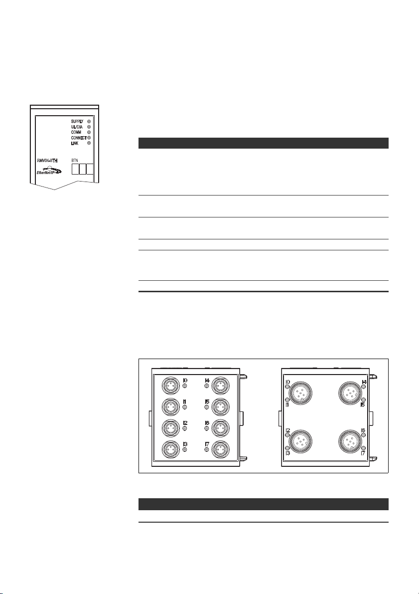
Abb. 3: Input-Modul 8fach: RMV04-8DI_M8 (links) und RMV04-8DI_M12 (rechts)
1 Beschriftungsfeld
2 RMV04-8DI_M8: 8 Eingänge, 8DI_M8
RMV04-8DI_M12: 4 Eingänge, 8DI_M12, doppelt belegt
3 LED-Anzeige (gelb, Zustand) je Eingang
Deutsch

12 AVENTICS | EtherNet/IP™ | R412012728–BDL–001–AC
1
2
3
4
6
5
1
2
3
45
6
Gerätebeschreibung
5.2.4 Output-Module
Die Output-Module zum Anschluss der Aktoren sind in zwei Ausführungen erhältlich:
W 8 x M8 (RMV04-8DO_M8) oder
W 4 x M12, doppelt belegt (RMV04-8DO_M12)
Abb. 4: Output-Modul 8fach: RMV04-8DO_M8 (links) und RMV04-8DO_M12 (rechts)
1 Beschriftungsfeld
2 LED-Anzeige (gelb, Zustand) je Ausgang
3 Zweifarbige LED-Anzeige Lastversorgung U
4 Anschluss Lastversorgung über M12-Stecker
5 RMV04-8DO_M8: 8 Ausgänge, 8DO_M8
RMV04-8DO_M12: 4 Ausgänge, 8DO_M12, doppelt belegt
6 Zweifarbige LED-Anzeige Lastversorgung U
Q2
Q1

Buskoppler
Input-/Output-Module
AVENTICS | EtherNet/IP™ | R412012728–BDL–001–AC 13
Montage
6 Montage
6.1 Ventilsystem mit Buskoppler montieren
Sie erhalten Ihr individuell konfiguriertes Ventilsystem komplett verschraubt mit
allen Komponenten:
W Ventilträger
W Buskoppler
W gegebenenfalls bis zu sechs I/O-Module
W gegebenenfalls bis zu drei Modulerweiterungen
Die Montage des gesamten Ventilsystems ist in der beiliegenden Betriebsanleitung
für das VS ausführlich beschrieben. Die Einbaulage des montierten VS ist beliebig. Die
Abmessungen des kompletten VS variieren je nach Modulbestückung.
6.2 Module beschriften
O Beschriften Sie die für den Buskoppler vorgesehene/verwendete Adresse am
Buskoppler im Feld BTN.
O Beschriften Sie die Anschlüsse direkt auf den Beschriftungsfeldern der Input-/
Output-Module.
Die Zuordnung der Beschriftungsfelder zu den Anschlüssen ist durch die
Bezeichnung der Anschlüsse gegeben.
Abb. 5: Beschriftungsfelder am Buskoppler (CMS-B-BEIP), Input-Modul (8DI_M8)
und Output-Modul (8DO_M8), Beispiele
Deutsch

14 AVENTICS | EtherNet/IP™ | R412012728–BDL–001–AC
Montage
6.3 Buskoppler elektrisch anschließen
VORSICHT
Anliegende elektrische Spannung
Verletzungsgefahr durch elektrischen Schlag.
O Schalten Sie immer den betreffenden Anlagenteil spannungsfrei und drucklos,
bevor Sie am Ventilträger Module elektrisch anschließen.
ACHTUNG
Falsche Verkabelung
Eine falsche oder fehlerhafte Verkabelung führt zu Fehlfunktionen und zur
Beschädigung des Netzwerks.
O Halten Sie – sofern nicht anders erwähnt – die Richtlinie Network
Infrastructure for EtherNet/IP™ Publication Number: PUB00035R0 ein.
O Verwenden Sie nur Kabel, die den Spezifikationen des Feldbusses sowie den
Anforderungen bzgl. Geschwindigkeit und Länge der Verbindung entsprechen.
O Montieren Sie Kabel und Stecker fachgerecht entsprechend der
Montageanweisung, damit Schutzart und Zugentlastung gewährleistet sind.
ACHTUNG
Stromfluss durch Potenzialunterschiede am Schirm
Über den Schirm des Buskabels dürfen keine durch Potenzialunterschiede
bedingten Ausgleichsströme fließen, da dadurch die Schirmung aufgehoben wird
und die Leitung sowie der angeschlossene Buskoppler beschädigt werden können.
O Verbinden Sie gegebenenfalls die Messpunkte der Anlage über eine separate
Leitung.
6.3.1 Allgemeine Hinweise zum Anschluss des Buskopplers
Benutzen Sie für das Anschließen der Module konfektionierte
Steckerverbindungen und Kabel.
O Beachten Sie die in Tab. 5 dargestellte Pin-Belegung, wenn Sie keine
konfektionierten Steckverbindungen und Kabel verwenden.

2
1
43
5
2
3
4
1
BUS X72
1
2
AVENTICS | EtherNet/IP™ | R412012728–BDL–001–AC 15
Montage
Tabelle 5: Pin- Belegung X71 (RS232), M12, 5-polig
Pin Signal Bedeutung
1 nc nicht angeschlossen
2 nc nicht angeschlossen
3 RXD Empfangsdaten
4GND Bezugspotenzial zu 0V
5TXD Sendedaten
Tabelle 6: Belegung X72 (BUS), M12, D-codiert
Pin Signal Bedeutung
1 TD+ Transmit pos.
2RD+ Receive pos.
3TD- Transmit neg.
4RD- Receive neg.
1 TD+ Transmit pos.
Anschlusstechnik und Steckerbelegung entsprechen den Vorgaben der
technischen Richtlinie Network Infrastructure for EtherNet/IP™ Publication
Number: PUB00035R0.
6.3.2 Buskoppler anschließen
1. Stellen Sie die korrekte Pin-Belegung (siehe Tab. 6 auf Seite 15) Ihrer
Steckerverbindungen her, wenn Sie eine selbst konfektionierte Verkabelung
verwenden.
2. Schließen Sie die ankommende Busleitung an X72 (1) an und verbinden Sie das
Modul mit einem Hub oder Switch falls noch weitere Teilnehmer angeschlossen
werden sollen.
3. Versehen Sie den Stecker X71 (2) mit einer Abdeckkappe.
4. Schließen Sie den Schirm an beiden Seiten des Buskabels direkt an das
Steckergehäuse (EMV-Gehäuse) an, wenn Sie selbst konfektionierte Kabel und
Stecker mit Metallgehäuse verwenden. So schützen Sie die Datenleitungen gegen
Störungseinkopplungen. Stellen Sie sicher, dass das Steckergehäuse fest mit
dem Buskopplergehäuse verbunden ist.
6.3.3 Logik- und Lastversorgung des Buskopplers anschließen
Über den Gerätestecker X10 (POWER) werden die Ventile und der Buskoppler mit
Betriebsspannung versorgt.
Wenn Sie die Logik- und Lastversorgung des Buskopplers anschließen, müssen Sie
die in Tab. 7 dargestellte Pin-Belegung sicherstellen.
POW ER
X10
2
1
43
Tabelle 7: Belegung des Gerätesteckers X10 (POWER), M12, A-codiert
Pin X10 Belegung
1U
2U
3 OV Masse für U
Spannungsversorgung Buskoppler-Logik und
L
Sensorversorgung der digitalen Eingangsmodule
erste Spannungsversorgung Ventile
Q1
und U
L, UQ1
Q2
4UQ2zweite Spannungsversorgung Ventile
Deutsch

16 AVENTICS | EtherNet/IP™ | R412012728–BDL–001–AC
Montage
W UL, UQ1 und UQ2 sind galvanisch miteinander verbunden.
W Über die Ventilversorgung U
werden.
W Die Zuordnung der Ventilgruppen (4 oder 8 Ventile) erfolgt über die
Schiebeschalter S4, S5 und S6 (siehe „Ventilversorgung zuordnen“ auf Seite 20).
Dadurch ist z. B. eine Abschaltung vor NOT-AUS bzw. nach NOT-AUS möglich.
Das Kabel für die Lastversorgung muss folgende Anforderungen erfüllen:
W
Kabelbuchse: 4-polig, A-codiert ohne Mittelloch
W Leitungsquerschnitt: je Ader > 0,5 mm2
W Länge: max. 20 m
Tabelle 8: Stromaufnahme an X10 (POWER) am Buskoppler
Signal Belegung Gesamtstrom
U
L
U
Q1
U
Q2
Die 24-V-Versorgung kann aus einem gemeinsamen Netzteil erfolgen.
Logik und Eingänge max. 1 A
Ventile max. 1 A
Ventile max. 1 A
und UQ2 können die Ventile gruppenweise versorgt
Q1
VORSICHT
Gefährliche Spannungen
Ein Netzteil mit nicht sicherer Trennung kann im Fehlerfall zu gefährlichen
Spannungen führen. Verletzungen durch Stromschlag und Schädigung des Systems
können die Folgen sein.
O Verwenden Sie nur ein Netzteil mit einer sicheren Trennung nach EN 60747,
Klassifikation VDE 0551! Damit gelten die entsprechenden Stromkreise als
SELV/PELV-Stromkreise nach IEC 60364-4-41.
So schließen Sie die Lastversorgung des Buskopplers an:
1. Stellen Sie die korrekte Pin-Belegung (siehe Tab. 7 auf Seite 15) Ihrer
Steckerverbindungen her, wenn Sie eine selbst konfektionierte Verkabelung
verwenden.
2. Schließen Sie mit der Kupplungsdose (siehe „Ersatzteile und Zubehör“ auf Seite
37) die Betriebsspannungen an den Buskoppler an.
3.
Kontrollieren Sie die Spezifikationen der Betriebsspannungen anhand der
elektrischen Kenngrößen und halten Sie diese ein (siehe Kapitel „Technische Daten“
auf Seite 36).
4. Stellen Sie die Leistungen gemäß Tab. 8, Seite 16 bereit. Wählen Sie die
Kabelquerschnitte entsprechend der Kabellänge und der auftretenden Ströme.

AVENTICS | EtherNet/IP™ | R412012728–BDL–001–AC 17
4
31
I0…I7
2
3
4
1
5
6.3.4 Input-/Output-Module 8fach anschließen
VORSICHT
Frei zugängliche stromführende Teile
Gefahr von Stromschlag bei Berührung!
O
Halten Sie beim Anschluss der Peripherie (E/A-Schnittstelle) die Anforderungen
des Berührungsschutzes gemäß EN 50178, Klassifikation VDE 0160 ein.
Montage
Input-Modul
Output-Modul
1. Verdrahten Sie die Eingänge nach Tab. 9 (DI8_M8) bzw. nach Tab. 10 (DI8_M12).
2. Schließen Sie die elektrischen Ein-/Ausgänge mit M8- oder M12-
Kupplungssteckern (Zubehör) an die I/O-Module an.
3. Verschließen Sie nicht belegte Gerätedosen mit der M8- oder M12-Schutzkappe
(Zubehör), um die Schutzart IP65 zu gewährleisten.
Der Summenstrom aller Sensorversorgungen (Pin 1) an einem Ventilsystem
darf 0,7 A nicht überschreiten.
Tabelle 9: Belegung der Eingänge beim Input-Modul 8fach, DI8_M8, Buchse M8x1
Pin Signal Belegung
1 SENSOR+ Sensorversorgung +
3SENSOR– Bezugspotenzial
4 I0 bis I7 Sensorsignal
Gehäuse liegt auf Shield-Potenzial
Tabelle 10: Belegung der Eingänge beim Input-Modul 8fach, DI8_M12,Buchse M12x1
Pin Signal Belegung
1SENSOR+
2 I1, I3, I5 oder I7 Sensorsignal
3SENSOR– GND-Bezugspotenzial
4 I0, I2, I4 oder I6 Sensorsignal
5NC nicht belegt
Gehäuse liegt auf Shield-Potenzial
1. Verdrahten Sie die Ausgänge nach Tab. 11 (DO8_M8) bzw. nach Tab. 12
(DO8_M12).
2. Schließen Sie die elektrischen Ein-/Ausgänge mit M8- oder M12-
Kupplungssteckern (Zubehör) an die I/O-Module an.
3. Verschließen Sie nicht belegte Gerätedosen mit der M8- oder M12-Schutzkappe
(Zubehör), um die Schutzart IP65 zu gewährleisten.
24-V-Sensorversorgung +
Deutsch

18 AVENTICS | EtherNet/IP™ | R412012728–BDL–001–AC
4
31
O0…O7
2
3
4
1
5
Montage
Tabelle 11: Belegung der Ausgänge beim Output-Modul 8fach, DO8_M8, Buchse
M8x1
Pin Signal Belegung
1frei nicht belegt
4 Ox Ausgangssignal Ox
3GND GND-Bezug des Aktors
Gehäuse liegt auf Shield-Potenzial
Tabelle 12: Belegung der Ausgänge beim Output-Modul 8fach, DO8_M12, Buchse
M12x1
Pin Signal Belegung
1NC nicht belegt
2 O1, O3, O5 oder O7 Ausgangssignal
3GND Bezugspotenzial
4 O0, O2, O4 oder O6 Ausgangssignal
5NC nicht belegt
Gehäuse liegt auf Shield-Potenzial
ACHTUNG
(Nennspannung 24 V)
Zu hoher Summenstrom
Jeder Ausgang ist für einen Dauerstrom von max. 0,5 A ausgelegt. Bei
Strombelastungen über 0,5 A je Ausgang kann das System beschädigt werden.
O Achten Sie darauf, dass die Strombelastung von 0,5 A je Ausgang nicht
überschritten wird.
6.3.5 Lastversorgung des Output-Moduls anschließen
Jedes Output-Modul besitzt einen eigenen M12-Anschluss zur Lastversorgung.
Jeweils 4 Ausgänge werden über eine Lastspannung versorgt. Die Spannungen U
sind galvanisch voneinander getrennt.
und U
Q2
Das Anschlusskabel für die Lastversorgung der Output-Module muss folgende
Anforderungen erfüllen:
W Kabelbuchse: M12x1, 4-polig, A-codiert ohne Mittelloch (zur Gewährleistung der
Verstecksicherheit)
W Leitungsquerschnitt: je Ader >
W Länge: max. 20 m
1. Stellen Sie die korrekte Pin-Belegung (siehe Tab. 13) Ihrer Steckerverbindungen
her, wenn Sie eine selbst konfektionierte Verkabelung verwenden.
2. Schließen Sie mit dem M12-Stecker die Lastversorgung an.
0,5 mm2
Q1

AVENTICS | EtherNet/IP™ | R412012728–BDL–001–AC 19
2
1
43
POW ER
X10
2
1
Montage
Tabelle 13: Belegung der Lastversorgung beim Output-Modul 8fach, DO8, M12x1, Acodiert
Pin X10 Belegung
10V_U
2 24V_U
30V_U
4 24V_U
Q2
Q1
GND-Bezug für Versorgungsspannung 2
24-V-Versorgungsspannung 1 für Ausgänge O0 bis O3
Q1
GND-Bezug für Versorgungsspannung 1
24-V-Versorgungsspannung 2 für Ausgänge O4 bis O7
Q2
6.3.6 FE-Anschluss
O Verbinden Sie zur Ableitung von EMV-Störungen den FE-Anschluss (2) an der
linken Endplatte über eine niederimpedante Leitung mit der Funktionserde.
Empfohlener Kabelquerschnitt: 10 mm
2
VORSICHT
Bei Modulerweiterungen (optional): unvollständige Erdung
Wenn Modulerweiterungen verwendet werden, ist durch das Kunststoffgehäuse
der Modulerweiterungen die Erdung am FE-Anschluss (2) nicht ausreichend.
O
Bei Verwendung von Modulerweiterungen verbinden Sie den FE-Anschluss jeder
Modulerweiterung
Funktionserde.
O Beim HF04-/HF04XF-Ventilblock verbinden Sie zur Ableitung von EMV-Störungen
den FE-Anschluss (1) am Ventilblock über eine niederimpedante Leitung mit der
Funktionserde.
zusätzlich
über eine niederimpedante Leitung mit der
Deutsch

20 AVENTICS | EtherNet/IP™ | R412012728–BDL–001–AC
B
A
Inbetriebnahme und Bedienung
7 Inbetriebnahme und Bedienung
7.1 Voreinstellungen vornehmen
Folgende Voreinstellungen müssen Sie durchführen:
W Ventilversorgung zuordnen
7.1.1 Ventilversorgung zuordnen
Die Schalter S4, S5 und S6 für die Zuordnung der Ventilversorgung befinden sich
unter der PG-Verschraubung B (siehe Abb. 6). Jedem Schalter sind zugeordnet:
W 4 Doppelanschlussplatten für beidseitig betätigte Ventile (mit Spulen 12 und 14)
oder
W 8 Doppelanschlussplatten für einseitig betätigte Ventile (mit Spule 14).
S6
S5
S4
U
Q1UQ2
Abb. 6: Schalter S4, S5, S6 für die Zuordnung der Ventilversorgungsspannungen
Über diese Schalter können die Ventile in Gruppen den Versorgungsspannungen U
und UQ2 zugeordnet werden.
Alle Ventile sind im Auslieferungszustand der Spannung U
Tabelle 14: Zuordnung der Schalter S4, S5 und S6
Schalter Byte
S4 0 1 – 4 1 – 8
S5 1 5 – 8 9 – 16
S6 2, 3 09–16 017 – 32
, UQ2)
(U
Q1
Q1
zugeordnet.
Q1
Doppelanschlussplatten für
beidseitig betätigte Ventile
(Spulen 12, 14)
Doppelanschlussplatten für
einseitig betätigte Ventile
(Spulen 14)
ACHTUNG
Spannung an Schaltern
Schalter können beschädigt werden, wenn bei ihrer Bedienung eine Spannung
anliegt.
O
Betätigen Sie die Schalter nur in spannungslosem Zustand!

AVENTICS | EtherNet/IP™ | R412012728–BDL–001–AC 21
Inbetriebnahme und Bedienung
So ordnen Sie die Ventilversorgung zu:
1. Öffnen Sie die untere Schraubkappe B (siehe Abb. 6 auf Seite 20).
2. Ordnen Sie mit Hilfe der Schalter S4, S5 und S6 jeder Ventilgruppe eine der
beiden Versorgungsspannungen U
Seite 20).
Nachfolgend finden Sie Beispiele für die Zuordnung der Schalter S4, S5 und S6 und
der Versorgung montierter Ventile in Tab. 15 auf Seite 22 (Beispiel 1 bis 3) und Tab. 16
auf Seite 23 (Beispiel 4 bis 6). Darin sind folgende Beispielkombinationen aufgeführt:
1)
Beispiele
Verwendete Doppelanschlussplatten2)
Beispiel 1 Doppelanschlussplatten für beidseitig
betätigte Ventile
Beispiel 2 Doppelanschlussplatten für beidseitig
betätigte Ventile
Beispiel 3 Doppelanschlussplatten für beidseitig
betätigte Ventile
Beispiel 4 Doppelanschlussplatten für einseitig
betätigte Ventile
Beispiel 5 Doppelanschlussplatten für beidseitig
betätigte Ventile
kombiniert mit
Doppelanschlussplatten für einseitig
betätigte Ventile
Beispiel 6 Doppelanschlussplatten für beidseitig
betätigte Ventile
kombiniert mit
Doppelanschlussplatten für einseitig
betätigte Ventile
1)
Diese Beispiele gelten nur, wenn keine Modulerweiterungen vorhanden sind. Entsprechend
Ihren Anforderungen können Sie auch andere Kombinationen wählen.
2)
Von der elektrischen Anschlussseite aus betrachtet, müssen zuerst die Doppelanschlussplatten
für beidseitig betätigte Ventile und danach die für einseitig betätigte Ventile angeordnet werden.
3)
Die maximale Spulenzahl bezogen auf alle Anschlussplatten beträgt 32.
oder UQ2 zu (siehe Abb. 6 und Tab. 14 auf
Q1
3)
Ventilbestückung
beidseitig betätigte
Ventile
einseitig betätigte Ventile
ein- und beidseitig
betätigte Ventile
einseitig betätigte Ventile
beidseitig betätigte
Ventile
einseitig betätigte Ventile
ein- und beidseitig
betätigte Ventile
einseitig betätigte Ventile
Deutsch

22 AVENTICS | EtherNet/IP™ | R412012728–BDL–001–AC
Inbetriebnahme und Bedienung
Tabelle 15: Beispiele1) für die Zuordnung von Schaltern und Ventilversorgung
Beispiel 1 Beispiel 2 Beispiel 3
Doppelanschlussplatte für beidseitig betätigte Ventile
Byte
Schalter
Ventilplatz
Adresse
S4 0 A0.0 1 14
A0.1 12 – 12
A0.2 2 14
A0.3 12 – 12
A0.4 3 14
A0.5 12 – 12
A0.6 4 14
A0.7 12 – 12
S5 1 A1.0 5 14
A1.1 12 – 12
A1.2 6 14
A1.3 12 – –
A1.4 7 14
A1.5 12 – –
A1.6 8 14
A1.7 12 – –
S6 2 A2.0 9 14
A2.1 12 – –
A2.2 10 14
A2.3 12 – 12
A2.4 11 14
A2.5 12 – 12
A2.6 12 14
A2.7 12 – –
S6 3 A3.0 13 14
A3.1 12 – –
A3.2 14 14
A3.3 12 – 12
A3.4 15 14
A3.5 12 – 12
A3.6 16 14
A3.7 12 – –
1)
Weiße Felder kennzeichnen Ventilplätze mit beidseitig betätigten Ventilen.
Grau unterlegte Felder kennzeichnen Ventilplätze mit einseitig betätigten Ventilen
Spule
1)
LED
Ventilplatz
Spule
2)
LED
Ventilplatz
Spule
2)
LED
114114
214214
314314
414414
514514
614614
714714
814814
914914
10 14 10 14
11 14 11 14
12 14 12 14
13 14 914
14 14 10 14
15 14 11 14
16 14 12 14

AVENTICS | EtherNet/IP™ | R412012728–BDL–001–AC 23
Inbetriebnahme und Bedienung
Tabelle 16: Beispiele
1)
für die Zuordnung von Schaltern und Ventilversorgung
Beispiel 4 Beispiel 5 Beispiel 6
Doppelanschluss-
platte für einseitig
Byte
Schalter
S4 0 A0.0
S5 1 A1.0
S6 2 A2.0
S6 3 A3.0
1)
Weiße Felder kennzeichnen Ventilplätze mit beidseitig betätigten Ventilen.
Grau unterlegte Felder kennzeichnen Ventilplätze mit einseitig betätigten Ventilen.
betätigte Ventile
Ventil-
Adresse
platz
Spule
1)
LED
114114114
A0.1
A0.2
A0.3
A0.4
A0.5
A0.6
A0.7
2141212
314214214
414 12 –
514314314
614 12 –
714414414
8141212
914 514514
A1.1
10 14 614 12
A1.2
11 14 714614
A1.3
12 14 814 12
A1.4
13 14 914714
A1.5
14 14 10 14 814
A1.6
15 14 11 14 914
A1.7
16 14 12 14 10 14
17 14 13 14 11 14
A2.1
18 14 14 14 12 14
A2.2
19 14 15 14 13 14
A2.3
20 14 16 14 14 14
A2.4
21 14 17 14 15 14
A2.5
22 14 18 14 16 14
A2.6
23 14 19 14 17 14
A2.7
24 14 20 14 18 14
25 14 21 14 19 14
A3.1
26 14 22 14 20 14
A3.2
27 14 23 14 21 14
A3.3
28 14 24 14 22 14
A3.4
29 14 25 14 23 14
A3.5
30 14 26 14 24 14
A3.6
31 14 27 14 25 14
A3.7
32 14 28 14 26 14
Doppelanschlussplatte
für ein- und beidseitig
betätigte Ventile
Ventilplatz
Spule
2)
LED
Ventilplatz
Spule
2)
LED
Deutsch

24 AVENTICS | EtherNet/IP™ | R412012728–BDL–001–AC
Inbetriebnahme und Bedienung
7.2 Buskoppler konfigurieren
Die Beschreibung in diesem Kapitel bezieht sich auf die Software BOOTP/DHCP Server
Version 2.3.2.0 von Rockwell Automation Inc. Die Software enthält auch eine OnlineDokumentation, die Sie bei der Bedienung berücksichtigen müssen.
Die in diesem Abschnitt dargestellten Konfigurierungsschritte sind den bereits
beschriebenen Einstellungen am Buskoppler (siehe „Voreinstellungen vornehmen“ auf
Seite 20) übergeordnet und Teil der Busmasterkonfiguration des Gesamtsystems.
Die beschriebenen Arbeiten dürfen nur von einer Elektronikfachkraft und unter
Beachtung der Dokumentation des Betreibers zur Konfiguration des
Busmasters sowie der geltenden technischen Normen, Richtlinien und
Sicherheitsvorschriften durchgeführt werden.
Vor der Konfiguration müssen Sie folgende Arbeiten am Buskoppler durchgeführt
und abgeschlossen haben:
W Sie haben den Buskoppler und den Ventilträger montiert (siehe „Montage“ auf
Seite 13).
W Sie haben den Buskoppler angeschlossen
(siehe „Buskoppler elektrisch anschließen“ auf Seite 14).
W Sie haben die Voreinstellungen vorgenommen (siehe „Voreinstellungen
vornehmen“ auf Seite 20).
Die Konfiguration kann auch mit einer anderen Konfigurationssoftware, unter
Berücksichtigung der beschriebenen Parameter und Einstellungen,
durchgeführt werden.
7.2.1 Bussystem konfigurieren
EtherNet/IP™ steht für „Ethernet Industrial Protocol". Es ist ein offenes Bussystem, das
auf dem IEEE 802.3 Standard basiert und die weit verbreitete TCP/IP-Protokollfamilie
unterstützt. Aus diesem Grund unterliegt es auch den Vorgaben und Einschränkungen
bei der Vergabe von IP-Adressen (RFC: 791 INTERNET PROTOCOL; DARPA INTERNET
PROGRAM PROTOCOL SPECIFICATION September 1981). Um die Probleme einer
werkseitig statischen IP-Adresse zu umgehen, ist die Buseinheit standardmäßig auf die
Adressvergabe mittels DHCP-Protokoll eingestellt.
Mit entsprechenden Tools kann dann eine dynamische oder statische IP-Adresse
vergeben werden.
Bevor Sie mit der Konfiguration des Bussystems beginnen, konsultieren Sie Ihren
Netzwerk-Administrator, wie Ihr Netzwerk konfiguriert werden soll. Erfragen Sie die
Werte für Subnet Mask, Gateway, Primary DNS, Secondary DNS und Domain Name.
Um das Bussystem zu konfigurieren:
1. Starten Sie das Programm BOOTP/DHCP Server.
Beim ersten Start müssen die Netzwerk-Einstellungen angepasst werden
(Schritte 2 bis 4).
2.
Klicken Sie in der Menüleiste auf „Tools“ > „Network Settings“.
3. Geben Sie die Werte ein für „Subnet Mask“, „Gateway“, „Primary DNS“,
„Secondary DNS“ und „Domain Name“.
4. Klicken Sie auf „OK“.

AVENTICS | EtherNet/IP™ | R412012728–BDL–001–AC 25
Inbetriebnahme und Bedienung
Abb. 7: Dialogfenster BOOTP/DHCP Server, Network Settings
Der Buskoppler sendet eine DHCP-Anfrage mit seiner individuellen
Hardwareadresse (MAC-Adresse). Im Fenster „Request History“ erscheint eine
Zeile.
Beispiel: „13:57:39 DHCP 00:04:F3:00:1C:40“
5. Klicken Sie mit der rechten Maustaste auf diese Zeile.
6. Klicken Sie auf „Add to Relation List“.
Das Fenster „New Entry“ erscheint.
7. Tragen Sie die IP-Adresse ein und bestätigen Sie mit „OK“.
Abb. 8: Dialogfenster BOOTP/DHCP Server, New Entry
Die IP-Adresse wird in die Relation List übernommen und bei der nächsten
Anfrage an das entsprechende Modul übergeben.
Im Fenster „Request History“ erscheint eine Zeile.
Beispiel: „14:00:32 DHCP 00:04:F3:00:1C:40 192.168.0.10“
Deutsch

26 AVENTICS | EtherNet/IP™ | R412012728–BDL–001–AC
Inbetriebnahme und Bedienung
Abb. 9: Dialogfenster BOOTP/DHCP Server, Relation List
7.2.2 Adressliste speichern
Um nicht bei jedem Programmstart den einzelnen Teilnehmern manuell eine IPAdresse zuweisen zu müssen, können Sie die Liste mit „File“ > „Save As“ speichern.
Nach dem nächsten Programmstart können Sie die Liste mit „File“ > „Open“ laden.
7.2.3 IP-Adresse ändern
Die vergebene IP-Adresse kann jederzeit geändert werden:
1. Klicken Sie mit der rechten Maustaste in der Relation List auf das Modul.
2. Klicken Sie auf „Properties“.
3. Geben Sie eine neue IP-Adresse ein und klicken Sie auf „OK“.
Nach dem nächsten Power-Reset wird die neue IP-Adresse übernommen.
Abb. 10: Dialogfenster BOOTP/DHCP Server, Properties

AVENTICS | EtherNet/IP™ | R412012728–BDL–001–AC 27
Inbetriebnahme und Bedienung
7.2.4 Dynamische oder statische IP-Adresse
Durch Anklicken des Schalters „Disable BOOTP/DHCP“ können Sie dem Modul die
aktuell zugewiesene IP-Adresse als statische IP-Adresse zuweisen. Damit wird für
dieses Gerät beim nächsten Systemstart kein BOOTP/DHCP Server mehr benötigt.
Durch Anklicken des Schalters „Enable DHCP“ können Sie die automatische
Adressvergabe wieder aktivieren, wenn das Modul in die Relation List eingetragen
und mit Rechtsklick markiert ist.
7.3 EIP
7.3.1 Feldbusmodul konfigurieren
Um das Modul von einer Steuerung aus ansprechen zu können, muss es zuerst
konfigu-riert werden.
Beispielhaft wird im Folgenden die Konfiguration an einer Logix5000 erläutert.
1. Starten Sie das Programm RSLogix5000 und das aktuelle Projekt.
Als Verbindungsstatus muss im Menü „Offline“ ausgewählt sein.
2. Klappen Sie in der Baumstruktur das Verzeichnis „I/O Configuration“ auf und
klicken Sie mit der rechten Maustaste auf den Zweig „Ethernet“.
3. Wählen Sie „New Module" aus.
4. Klicken Sie auf „ETHERNET-MODULE - Generic Ethernet Module" und bestätigen
Sie mit „OK“.
Abb. 11: Dialogfenster Select Module
Deutsch
28 AVENTICS | EtherNet/IP™ | R412012728–BDL–001–AC
Inbetriebnahme und Bedienung
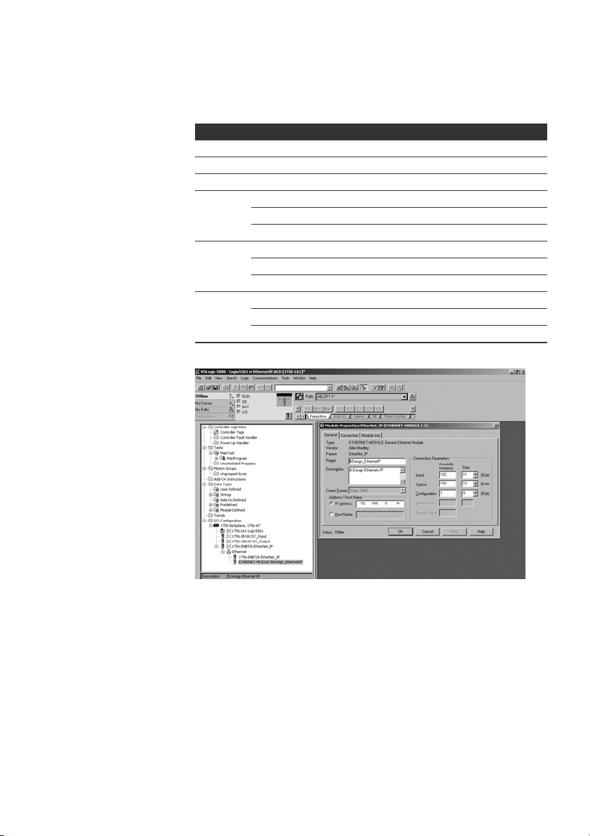
5. Tragen Sie in den Feldern der Registerkarte „General“ die entsprechenden Werte
ein:
Parameter Wert
Name: gemäß Projekt
Comm Format: „Data - SINT“
IP Address: gemäß Projekt
Input:
Assembly Instance: 102
Size: 11 (8-bit)
Output:
Assembly Instance: 100
Size: 10 (8-bit)
Configuration:
Assembly Instance: 1
Size: 0 (8-bit)
Abb. 12: Dialogfenster Module Properties: EtherNet_IP
6. Klicken Sie auf die Registerkarte „Connection“.
7. Tragen Sie im Feld „Requested Packet Interval (RPI)“ einen Wert von ≥ 10 ms ein
und bestätigen Sie mit „OK“.
Das konfigurierte Gerät erscheint unterhalb des Zweiges „Ethernet“ in der
Baumstruktur.
Sie können die Konfiguration überprüfen, indem Sie den Verbindungsstatus „Go
Online“ auswählen. Mögliche Konfigurationsfehler werden durch ein gelbes
Ausrufezeichen in der Baumstruktur angezeigt.

AVENTICS | EtherNet/IP™ | R412012728–BDL–001–AC 29
Inbetriebnahme und Bedienung
7.3.2 Ein- und Ausgänge konfigurieren
Die Ein- bzw. Ausgänge können, wie im folgenden Beispiel gezeigt, konfiguriert
werden.
1. Doppelklicken Sie im Programm RSLogix5000 in der Baumstruktur unter
„Controller Logix5561“auf den Zweig „Controller Tags“.
Im rechten Fensterbereich erscheinen verschiedene Menügruppen. Die
Menügruppe mit dem in der Konfiguration hinterlegten Namen (im Beispiel
„BDesign“) stellt die Ventileinheit B-Design EthernetIP dar.
2. Klappen Sie die Menügruppe „BDesign:O“ auf, indem Sie auf das „+“-Zeichen
klicken.
3. Klappen Sie die Menügruppe „BDesign:O Data“ auf, indem Sie auf das „+“-Zeichen
klicken.
Sie sehen das folgende Fenster:
Abb. 13: Fensterbereich Controller Tags
Sobald Sie die aufgelisteten Bytes (z. B. „BDesign:O.Data[0]“) mit einem Klick auf das
„+“-Zeichen aufklappen, werden die entsprechenden Bits angezeigt.
Input- und Diagnosedaten können Sie einsehen, wenn Sie die Menügruppe „BDesign:I“
aufklappen.
Beispiel:
BDesign:I.Data[6] (Module Diagnostics)
Bit Function
0 none <value = 0>
1 none <value = 0>
2Supply voltage for outputs 1-8
3 Supply voltage for outputs 9-16
4 Supply voltage for outputs 17-32
5 Electrical supply voltage for external modules
6 none <value = 0>
7 none <value = 0>
Deutsch
30 AVENTICS | EtherNet/IP™ | R412012728–BDL–001–AC
Inbetriebnahme und Bedienung
7.4 Test und Diagnose an den Modulen
7.4.1 Diagnoseanzeige am Buskoppler ablesen
Die LEDs auf der Frontplatte des Buskopplers geben die in Tab. 17 aufgeführten
Meldungen wieder.
O Überprüfen Sie vor der Inbetriebnahme und während des Betriebs regelmäßig die
Buskopplerfunktionen durch Ablesen der Diagnoseanzeigen.
LED Signal Beschreibung
Supply
(U
Q1/UQ2
U
L
Diagnosis grün keine Diagnosemeldung
COMM ohne Funktion
Connected grün „Unconnected!“ oder „Class1/3 Connection“ aufgebaut
Link physikalischer Ethernet Link aufgebaut
7.4.2 Sensoren am Input-Modul überprüfen
Für Kontrollzwecke steht auf dem Eingangsmodul für jeden Eingang eine LED zur
Verfügung. Sie leuchtet auf, wenn der Signalpegel „high“ ist.
O Überprüfen Sie vor der Inbetriebnahme die Funktionsfähigkeit und
Wirkungsweise der Sensoren durch Ablesen der LEDs.
grün Logikversorgung vorhanden
)
rot Überlast Geber- oder Ventilversorgung
grün Logikspannung vorhanden
aus keine Logikspannung vorhanden (U
rot Diagnosemeldung liegt vor
rot bei Class 1/3 Connection: SPS im STOP
Ventilversorgung U
(Sammeldiagnose)
Unterspannung (U
bei Class 1/3 Connection: SPS im RUN-Mode
Q1/UQ2
Q1/UQ2
in Ordnung
< 18,5 V)
<16V)
L
Abb. 14: LED-Anzeigen am Input-Modul M8 (links) und M12 (rechts)
LED Farbe Bedeutung
Eingang gelb Signalpegel High-Zustand

AVENTICS | EtherNet/IP™ | R412012728–BDL–001–AC 31
O
O
O
O
O
O
O
O
OO
Inbetriebnahme und Bedienung
7.4.3 Aktoren am Output-Modul überprüfen
O Überprüfen Sie vor der Inbetriebnahme die Funktionsfähigkeit und
Wirkungsweise der Aktoren mit Hilfe der LED-Anzeigen am Output-Modul.
Abb. 15: LED-Anzeigen am Output-Modul M8 (links) und M12 (rechts)
Tabelle 17: Bedeutung der LED-Anzeigen am Output-Modul
LED Farbe Bedeutung
U
Q1
U
Q2
O0 bis O7 aus zugehöriger Ausgang LOW-Pegel
grün Lastversorgung UQ1 vorhanden
rot Diagnose: Überlast/Kurzschluss auf angesteuertem
Ausgang O0, O1, O2 oder O3
aus Lastversorgung U
Q1 nicht vorhanden (z. B. NOT-AUS)
grün Lastversorgung UQ2 vorhanden
rot Diagnose: Überlast/Kurzschluss auf angesteuertem
Ausgang O4, O5, O6 oder O7
aus Lastversorgung U
nicht vorhanden (z. B. NOT-AUS)
Q2
gelb zugehöriger Ausgang HIGH-Pegel
Deutsch

32 AVENTICS | EtherNet/IP™ | R412012728–BDL–001–AC
Inbetriebnahme und Bedienung
7.5 Buskoppler in Betrieb nehmen
Bevor Sie das System in Betrieb nehmen, müssen Sie folgende Arbeiten durchgeführt
und abgeschlossen haben:
W Sie haben den Ventilträger und den Buskoppler montiert (siehe „Ventilsystem mit
Buskoppler montieren“ auf Seite 13).
W Sie haben den Buskoppler angeschlossen (siehe „Buskoppler elektrisch
anschließen“ auf Seite 14).
W Sie haben die Voreinstellungen und die Konfiguration durchgeführt (siehe
„Voreinstellungen vornehmen“ auf Seite 20 und „Buskoppler konfigurieren“ auf
Seite 24).
W Sie haben den Busmaster so konfiguriert, dass die Ventile und die Input-Module
richtig angesteuert werden.
W Sie haben den Diagnosetest der Input-/Output-Module durchgeführt (siehe „Test
und Diagnose an den Modulen“ auf Seite 30).
Die Inbetriebnahme und Bedienung darf nur von einer Elektro- oder
Pneumatikfachkraft oder von einer unterwiesenen Person unter der Leitung und
Aufsicht einer Fachkraft durchgeführt werden (siehe „Qualifikation des
Personals“ auf Seite 7).
VORSICHT
Unkontrollierte Bewegungen der Aktoren beim Einschalten der Pneumatik
Es besteht Verletzungsgefahr, wenn sich das System in einem undefinierten
Zustand befindet und wenn die Handhilfsbetätigungen nicht auf Position „0“
stehen.
O
Bringen Sie das System in einen definierten Zustand, bevor Sie es einschalten!
O Stellen Sie alle Handhilfsbetätigungen auf Position „0“.
O Stellen Sie sicher, dass sich keine Person innerhalb des Gefahrenbereichs
befindet, wenn Sie den Druck einschalten.
O Beachten Sie auch die entsprechenden Anweisungen und Warnhinweise der
Betriebsanleitung Ihres VS.
1. Schalten Sie die Betriebsspannung ein.
2. Überprüfen Sie die LED-Anzeigen an allen Modulen.
3. Schalten Sie die Druckluftversorgung ein.

AVENTICS | EtherNet/IP™ | R412012728–BDL–001–AC 33
Demontage und Austausch
8 Demontage und Austausch
Sie können je nach Bedarf den Buskoppler austauschen oder weitere/andere Input-/
Output-Module und Modulerweiterungen anbauen.
Die Gewährleistung von AVENTICS gilt nur für die ausgelieferte Konfiguration
und Erweiterungen, die bei der Konfiguration berücksichtigt wurden. Nach
einem Umbau, der über diese Erweiterungen hinausgeht, erlischt die
Gewährleistung.
8.1 Buskoppler austauschen
Beachten Sie Abb. 16 auf Seite 34.
VORSICHT
Anliegende elektrische Spannung und hoher Druck
Verletzungsgefahr durch elektrischen Schlag und plötzlichen Druckabbau.
O Schalten Sie das System drucklos und spannungsfrei, bevor Sie Module
austauschen.
1.
Trennen Sie die elektrischen Anschlüsse vom Buskoppler (4).
2. Lösen Sie die Endplatte (2) und, falls vorhanden, alle Input-/Output-Module links
vom Buskoppler (je 2 Innensechskantschrauben DIN 912 – M4 (1),
Schlüsselweite 3) und ziehen Sie diese von den Zugankern (5) ab.
3. Ziehen Sie den Buskoppler (4) von den Zugankern (5) ab.
4. Schieben Sie den neuen Buskoppler (4) auf die Zuganker (5) auf.
5. Stellen Sie sicher, dass
–die Zuganker (5) vollständig eingeschraubt sind und
–die Dichtungen (3) richtig eingelegt sind.
6. Schieben Sie zuerst die Input-/Output-Module, falls vorhanden, in der
ursprünglichen Reihenfolge und dann die Endplatte (2) links wieder auf die
Zuganker (5) und schrauben Sie diese an (je 2 Innensechskantschrauben
DIN 912 – M4 (1), Schlüsselweite 3).
Anzugsdrehmoment: 2,5 bis 3,0 Nm.
7. Führen Sie alle Voreinstellungen am neuen Buskoppler (4) durch (siehe
„Voreinstellungen vornehmen“ auf Seite 20).
8. Stellen Sie die Anschlüsse wieder her.
9. Überprüfen Sie die Konfiguration und passen Sie diese gegebenenfalls an (siehe
„Buskoppler konfigurieren“ auf Seite 24).
Deutsch

34 AVENTICS | EtherNet/IP™ | R412012728–BDL–001–AC
4
1
2
3
3
6
5
Demontage und Austausch
Abb. 16: Buskoppler austauschen, Beispiel
1 Innensechskantschrauben 4 Buskoppler
2 Endplatte links 5 Zuganker
3 Dichtung 6 Endplatte links mit Anschlüssen
8.2 Input-/Output-Modul(e) anbauen
Das Ventilsystem kann um Input- und Output-Module erweitert werden. Beachten Sie
Abb. 17 auf Seite 35.
VORSICHT
Anliegende elektrische Spannung und hoher Druck
Verletzungsgefahr durch elektrischen Schlag und plötzlichen Druckabbau.
O Schalten Sie das System drucklos und spannungsfrei, bevor Sie Module
austauschen.
Es dürfen insgesamt maximal 6 Module (Input- oder Output-Module) an einem
Ventilsystem montiert sein. Beachten Sie die zulässige Strombelastung!
1.
Lösen Sie die Endplatte links (2) vom Buskoppler (7) oder vom letzten Input-Modul
5
)/Output-Modul (4) des Ventilsystems (2 Innensechskantschrauben DIN 912 –
(
M4 (
2. Schrauben Sie die Zuganker (6) für Input-Module (5)/Output-Module (4) auf die
vorhandenen Zuganker (6) auf (2 Stück je Input-Modul (5)/Output-Modul (4)).
– Stellen Sie sicher, dass die Zuganker (6) vollständig eingeschraubt sind!
1
), Schlüsselweite 3) und ziehen Sie diese von den Zugankern (6) ab.

AVENTICS | EtherNet/IP™ | R412012728–BDL–001–AC 35
6
6
2
3
3
3
4
5
1
7
Demontage und Austausch
3. Schieben Sie das (weitere) Input-Modul (5)/Output-Modul (4) auf die Zuganker (6)
auf.
– Stellen Sie sicher, dass die Dichtungen (3) richtig eingelegt und die Kontakte
richtig gesteckt sind!
4. Schrauben Sie nach dem letzten Input-Modul (5) oder Output-Modul (4) die
Endplatte links (2) wieder an (2 Innensechskantschrauben DIN 912 – M4 (1),
Schlüsselweite 3).
Anzugsdrehmoment: 2,5 bis 3 Nm.
5. Stellen Sie die Anschlüsse her (siehe „Logik- und Lastversorgung des
Buskopplers anschließen“ auf Seite 15).
VORSICHT
Offenliegende Ein-/Ausgänge
Gefahr von Stromschlag bei Berührung, Kurzschluss und Schädigung des
Systems.
O
Verschließen Sie immer nicht benutzte Eingänge bzw. Ausgänge mit
Verschlusskappen (siehe „Ersatzteile und Zubehör“ auf Seite 37), um die
Schutzart IP65 einzuhalten.
6. Passen Sie die Konfiguration an (siehe „Buskoppler konfigurieren“ auf Seite 24).
Abb. 17: Input-/Output-Modul anbauen, Beispiel
1 Innensechskantschrauben 5 Input-Modul
2 Endplatte links 6 Zuganker
3 Dichtung 7 Buskoppler
4 Output-Modul
Deutsch

36 AVENTICS | EtherNet/IP™ | R412012728–BDL–001–AC
Pflege und Wartung
9 Pflege und Wartung
VORSICHT
Anliegende elektrische Spannung und hoher Druck
Verletzungsgefahr durch elektrischen Schlag und plötzlichen Druckabbau.
O Schalten Sie das System vor der Durchführung von Pflege- und
Wartungsarbeiten drucklos und spannungsfrei.
9.1 Module pflegen
ACHTUNG
Beschädigung der Gehäuseoberfläche durch Lösemittel und aggressive
Reinigungsmittel!
Die Oberflächen und Dichtungen können durch Lösemittel oder aggressive
Reinigungsmittel beschädigt werden.
O Verwenden Sie niemals Lösemittel oder aggressive Reinigungsmittel!
O Reinigen Sie das Gerät regelmäßig mit einem feuchten Lappen. Verwenden Sie
dazu nur Wasser oder ein mildes Reinigungsmittel.
9.2 Module warten
Der Buskoppler und die I/O-Module des VS sind wartungsfrei.
O Beachten Sie die Wartungsintervalle und Vorgaben der Gesamtanlage.
10 Technische Daten
10.1 Kenngrößen
Allgemein
Schutzart nach EN 60 529 / IEC 529 IP65 im montierten Zustand
Umgebungstemperatur ϑ
Elektromagnetische Verträglichkeit
Störaussendung EN 61000-6-4
Störfestigkeit EN 61000-6-2
U
0 °C bis +50 °C ohne Betauung

AVENTICS | EtherNet/IP™ | R412012728–BDL–001–AC 37
Ersatzteile und Zubehör
10.2 Buskoppler
Elektrik
Betriebsspannung Logik U
Betriebsspannung Last
U
, U
Q1
Q2
L
Schutzkleinspannung (SELV/PELV) nach EC 364-4-41,
24 V DC (+20 %/–15 %)
24 V DC (±10 %),
Restwelligkeit 0,5 %
10.3 Input-Module 8fach, RMV04-8DI_M8 und RMV04-
8DI_M12
Elektrik
Eingänge DIN EN 61131-2 8 digitale Eingänge, Typ 3,
Summenstrom der 24-V-Sensorversorgung für alle Eingangsmodule auf 0,7 A
begrenzt
Eingangsverzögerung 0 – 1 3 ms
Eingangsverzögerung 1 – 0 3 ms
Zweidraht-Näherungsschalter mit einem
Ruhestrom von max. 2,5 mA anschließbar
10.4 Output-Module 8fach, RMV04-8DO_M8 und RMV04-
8DO_M12
Elektrik
Ausgänge DIN EN 61131-2 8 digitale Ausgänge
Ausgangsspannung Nennwert 24 V
Ausgangsstrom Nennwert 0,5 A
Überlastschutz Abschaltung bei 0,6 bis 1,2 A
Leitungslänge für M8- und
M12-Anschluss
Spannungsversorgung
und U
U
Q1
Q2
Aus thermischen Gründen dürfen die Ausgänge
nicht längere Zeit über Nennstrom belastet werden.
Spannungsabfall bei H-Signal ≤ 1,5 V
Autom. Wiederanlauf bei reduzierter Last
max. 30 m
Nennwert 24 V
(+20 %/-15 %)
Deutsch
11 Ersatzteile und Zubehör
Buskoppler mit Feldbusprotokoll EtherNet/IP™
Zubehör
M12x1 Schutzkappe R419800769
Endplatte für Buskoppler
1)
Lieferung inkl. 2 Zuganker, Dichtung und Handbuch
2)
Lieferung inkl. 2 Befestigungsschrauben und 1 Dichtung
2)
1)
Bestellnummer
R412012755
R412003490

38 AVENTICS | EtherNet/IP™ | R412012728–BDL–001–AC
Entsorgung
11.1 Input-/Output-Modul 8fach, 8DI/8DO
Input-Modul 8fach (8 x M8)
Input-Modul 8fach (4 x M12)
Output-Modul 8fach (8 x M8)
Output-Modul 8fach (4 x M12)
Zubehör
Steckverbinder gerade, mit selbstsicherndem
Schraubverschluss, M8x1, 3-polig
1)
1)
1)
1)
Bestellcode Bestellnummer
8DI_M8 R412003489
8DI_M12 R412008040
8DO_M8 R412005968
8DO_M12 R412005968
Kabellänge 2 m 894 620 360 2
Kabellänge 5 m 894 620 361 2
Kabellänge 10 m894 620 362 2
Schutzkappe M8x1 für Eingänge (LE = 25
Stück)
Schutzkappe M12x1 für Eingänge (LE = 25 Stück) 182 331 200 1
Y-Verteiler M12 mit selbstsicherndem Schraubverschluss M12,
5-polig, 2 x Kabeldose M12, 1 x Kabelstecker M12
1)
Lieferung inkl. 2 Zuganker und 1 Dichtung
R412003493
894 100 239 2
11.2 Power-Stecker für Buskoppler und Output-Modul
Bestellnumme
Steckverbinder für
Spannungsversorgung,
Buchse M12x1, 4-polig
für Leitungs-Ø 4-8 mm, A-codiert
Steckverbinder für Input-/Output-Module M12x1 Stecker,
o
180
(X10, POWER) 894 105 432 4
o
90
(X10, POWER) 894 105 442 4
gerade
M12x1 Stecker,
gewinkelt
M12x1 Duo-Stecker
für Leitungs-Ø 3 mm
oder 5 mm
1 834 484 222
1 834 484 223
1 834 484 246
12 Entsorgung
Entsorgen Sie das Gerät nach den Bestimmungen Ihres Landes.
r

AVENTICS | EtherNet/IP™ | R412012728–BDL–001–AC 39
Stichwortverzeichnis
13 Stichwortverzeichnis
W A
Abkürzungen 6
W B
Beschriftung
Buskoppler 13
Input-/Output-Module 13
Buskoppler
Ersatzteile, Zubehör 37
technische Daten 37
Buskoppler
austauschen 33
Bussystem
konfigurieren 24
W D
Diagnoseanzeige,
Buskoppler 30
W E
Elektrischer Anschluss
Buskoppler 15
FE 19
Input-/Output-Module 17
Logik und
Lastversorgung 15
Schirmung 15
Entsorgung 38
W G
Gebrauch
bestimmungsgemäß 7
nicht
bestimmungsgemäß 7
W I
Inbetriebnahme
Diagnoseanzeige 30
Inbetriebnahme 32
Test/Diagnose 30
Voreinstellungen 20
Input-/Output-Module
anbauen 34
Beschreibung 11
Ersatzteile, Zubehör 38
Input-Modul, technische
Daten 37
W K
Kenngrößen 36
Komponenten
Buskoppler 10
Input-Module 11
Output-Module 12
Konfiguration
Buskoppler 24
W M
Montage
elektrische
Anschlüsse 14
FE-Anschluss 19
I/O-Module 8-fach
anschließen 17
Montagemöglichkeiten 1
3
W N
Normen 5, 8
Deutsch

40 AVENTICS | EtherNet/IP™ | R412012728–BDL–001–AC
Stichwortverzeichnis
W O
Output-Modul, technische
Daten 37
W Q
Qualilfikation, Personal 7
W S
Sicherheitshinweise
allgemein 7
bei der Montage 8
bei Inbetriebnahme und
Betrieb 8
Reinigung 8
Spannungsversorgung
Anschlusskabel 18
Steckverbindungen
X10 (POWER) 15
W T
Test und Diagnose
Buskoppler 30
Input-Modul 30
Output-Modul 31
W V
Ventilversorgung
zuordnen 20
Voreinstellungen
Ventilversorgung
zuordnen 20

AVENTICS | EtherNet/IP™ | R412012728–BDL–001–AC 41
Contents
1 About This Documentation ............................................... 5
1.1 Required and supplementary documentation....................... 5
1.2 Presentation of information ........................................................5
1.2.1 Notes on Safety ............................................................................. 5
1.2.2 Symbols ........................................................................................... 6
1.3 Abbreviations used ........................................................................6
2 Notes on Safety .................................................................. 6
2.1 About this chapter..........................................................................6
2.2 Intended use.....................................................................................7
2.3 Improper use ...................................................................................7
2.4 Personnel qualifications...............................................................7
2.5 General safety instructions .........................................................7
3 Applications ....................................................................... 8
4 Delivery contents ............................................................... 8
5 Device Description ............................................................. 9
5.1 Device overview of the valve system and modules .............9
5.2 Device components......................................................................10
5.2.1 Bus couplers ................................................................................ 10
5.2.2 Input/output modules ............................................................... 11
5.2.3 Input modules .............................................................................. 11
5.2.4 Output modules ........................................................................... 12
6 Assembly .......................................................................... 13
6.1 Assembling the valve system with bus coupler .................13
6.2 Labeling the module....................................................................13
6.3 Connecting the bus coupler electrically ................................14
6.3.1 General notes on connecting the bus coupler ................... 14
6.3.2 Connecting the bus coupler ..................................................... 15
6.3.3 Connecting the bus coupler logic and load supply ........... 15
6.3.4 Connecting the 8x input/output modules ............................ 17
6.3.5 Connecting the output module load supply ........................ 18
6.3.6 FE connection .............................................................................. 19
English

42 AVENTICS | EtherNet/IP™ | R412012728–BDL–001–AC
7 Commissioning and Operation ....................................... 20
7.1 Making settings .............................................................................20
7.1.1 Assigning the valve supply ...................................................... 20
7.2 Configuring the bus coupler......................................................24
7.2.1 Configuring the bus system .................................................... 24
7.2.2 Saving the address list ............................................................. 26
7.2.3 Change the IP address. ............................................................. 26
7.2.4 Dynamic or static IP address .................................................. 27
7.3 EIP.....................................................................................................27
7.3.1 Configuring the fieldbus module ........................................... 27
7.3.2 Configuring inputs and outputs .............................................. 29
7.4 Testing and diagnosis on the modules..................................30
7.4.1 Reading the bus coupler diagnostic display ...................... 30
7.4.2 Check sensors on the input module ..................................... 30
7.4.3 Check actuators on the output module ................................ 31
7.5 Commissioning the bus coupler ..............................................32
8 Disassembly and Exchange ............................................ 33
8.1 Exchange the bus coupler..........................................................33
8.2 Mounting input/output module(s)............................................34
9 Care and Maintenance .................................................... 36
9.1 Servicing the modules ................................................................36
9.2 Maintaining the modules............................................................36
10 Technical Data ................................................................. 36
10.1 Characteristics ..............................................................................36
10.2 Bus coupler ....................................................................................37
10.3 8x input modules, RMV04-8DI_M8 and
RMV04-8DI_M12 ...........................................................................37
10.4 8x output modules, RMV04-8DO_M8 and
RMV04-8DO_M12..........................................................................37
11 Spare parts and accessories ......................................... 37
11.1 8x input/output module, 8DI/8DO............................................38
11.2 Power plug for bus coupler and output module .................38
12 Disposal ............................................................................ 38
13 Index ................................................................................. 39

AVENTICS | EtherNet/IP™ | R412012728–BDL–001–AC 43
About This Documentation
1 About This Documentation
These instructions contain important information on the safe and appropriate
assembly, operation, and maintenance of the bus coupler and how to remedy simple
malfunctions yourself.
O Read this documentation completely, especially chapter 2 “Notes on Safety” on
page 44, before working with the bus coupler.
1.1 Required and supplementary documentation
O Only commission the product once you have obtained the following
documentation and understood and complied with its contents.
Table 1: Required and supplementary documentation
Title Document number Document type
Documentation of the valve system
HF04 D-SUB
Documentation of the valve system
HF03-LG
Documentation of the valve system
CD01/02-PI
Documentation of the B-design
stand-alone module extension
System documentation
Further information on the components can be found in the online catalog at
www.aventics.com/pneumatics-catalog.
R412015493 Instructions
R412008233 Instructions
R412012449 Instructions
R412008961 Instructions
1.2 Presentation of information
To allow you to begin working with the product quickly and safely, uniform safety
instructions, symbols, terms, and abbreviations are used in this documentation.
For better understanding, these are explained in the following sections.
1.2.1 Notes on Safety
In this documentation, there are safety instructions before the steps whenever there
is a risk of personal injury or damage to equipment. The measures described to avoid
these hazards must be observed.
Safety instructions are set out as follows:
SIGNAL WORD
Hazard type and source
Consequences
O Precautions
W Safety sign: draws attention to the risk
W Signal word: identifies the degree of hazard
W Hazard type and source: identifies the hazard type and source
W Consequences: describes what occurs when the safety instructions are not
complied with
W Precautions: states how the hazard can be avoided
English

44 AVENTICS | EtherNet/IP™ | R412012728–BDL–001–AC
Notes on Safety
Table 2: Hazard classes according to ANSI Z 535.6-2006
Safety sign, signal word Meaning
Indicates a hazardous situation which,
CAUTION
NOTICE
if not avoided, could result in minor or
moderate injury.
Indicates that damage may be inflicted on
the product or the environment.
1.2.2 Symbols
The following symbols indicate information that is not relevant for safety but that
helps in comprehending the documentation.
Table 3: Meaning of the symbols
Symbol Meaning
If this information is disregarded, the product cannot be used
or operated optimally.
O Individual, independent action
1.
2.
3.
Numbered steps:
The numbers indicate sequential steps.
1.3 Abbreviations used
Table 4: Abbreviations used
Abbreviation Meaning
VS Valve system
EIP EtherNet/IP™
EDS Device master data
2 Notes on Safety
2.1 About this chapter
The product has been manufactured according to the accepted rules of current
technology. Even so, there is risk of injury and damage to equipment if the following
chapter and safety instructions of this documentation are not followed.
O Read these instructions completely before working with the product.
O Keep this documentation in a location where it is accessible to all users
at all times.
O Always include the documentation when you pass the product on to third parties.

AVENTICS | EtherNet/IP™ | R412012728–BDL–001–AC 45
Notes on Safety
2.2 Intended use
O The Bus coupler is only intended for industrial applications.
O The pressure regulator may only be used within the limits listed in the technical
data.
Intended use includes having read and understood this documentation, especially the
chapter “Notes on Safety”.
2.3 Improper use
Any use other than that described under Intended use is improper and is not
permitted.
The installation or use of unsuitable products in safety-relevant applications can
result in unanticipated operating states in the application that can lead to personal
injury or damage to equipment. Therefore, only use a product in safety-relevant
applications if such use is specifically stated and permitted in the product
documentation. AVENTICS GmbH is not liable for any damages resulting from
improper use. The user alone bears the risks of improper use of the product.
It is considered improper use when the Bus coupler
W
are used for any application not stated in these instructions or
W if it is used under operating conditions that deviate from those described in these
instructions.
2.4 Personnel qualifications
The work described in this documentation requires basic electrical and pneumatic
knowledge, as well as knowledge of the appropriate technical terms. In order to
ensure safe use, these activities may therefore only be carried out by qualified
technical personnel or an instructed person under the direction and supervision
of qualified personnel.
Qualified personnel are those who can recognize possible hazards and institute the
appropriate safety measures, due to their professional training, knowledge, and
experience, as well as their understanding of the relevant regulations pertaining
to the work to be done. Qualified personnel must observe the rules relevant to the
subject area.
2.5 General safety instructions
W Observe the regulations for accident prevention and environmental protection
in the country where the product is used and at the workplace.
W Do not modify or convert the device.
W
Only use the device within the performance range provided in the technical data.
W Do not place any mechanical loads on the device under any circumstances. Do not
place loose objects on it.
W
This device may only be used for industrial applications (class A). An individual license
must be obtained from the authorities or an inspection center for systems that are
to be used in a residential area (residential, business, and commercial areas). In
Germany, these individual licenses are issued by the Regulating Agency for
Telecommunications and Post (Regulierungsbehörde für Telekommunikation und
Post, RegTP).
W Ensure that the power supply is within the stipulated tolerance for the modules.
W Observe the safety notes in the operating instructions for your valve system.
English

46 AVENTICS | EtherNet/IP™ | R412012728–BDL–001–AC
Applications
W
A 24 V power pack supplies all components with electricity. The power pack must be
fitted with a safe isolation in accordance with EN 60742, VDE 0551 classification.
This ensures that the electric circuits comply with SELV/PELV electric circuits in
accordance with IEC 60364-4-41.
W Switch off the operating voltage before connecting or disconnecting plugs.
W
On installation
During commissioning
During operation
During cleaning
The warranty only applies to the delivered configuration. The warranty will not apply
if the product is incorrectly assembled.
W Make sure the relevant system component is not under pressure or voltage befor e
assembly or disassembly. Ensure that the system is prevented from power
restoration during assembly work.
W Ground the modules and valve system. Observe the following standards when
installing the system:
– DIN EN 50178, classification VDE 0160
– VDE 0100
W Installation may only be performed in a voltage-free and pressure-free state and
only by a qualified technician. In order to avoid accidents caused by dangerous
movements of the actuators, electrical commissioning is to be carried out only in
a pressure-free state.
W Do not put the system into operation before it is completely assembled as well
as correctly wired and configured, and after it has been properly tested.
W The device is subject to the restrictions in the IP 65 protection class. Before
commissioning, make sure that all the connection seals and plugs are leaktight
to prevent fluids and foreign bodies from penetrating the device.
W Make sure that there is a sufficient exchange of air or enough cooling if your valve
system has any of the following:
– Full equipment status
– Continuously loaded solenoid valves
W Never use aggressive solvents or detergents. Only clean the device using
a slightly damp cloth. Only use water and, if necessary, a mild detergent.
3 Applications
The bus coupler is used to electrically control valves via the EtherNet/IP™ field bus
system. In addition, input/output modules allow electrical input and output signals to
be connected via the valve system's bus connection.
The bus coupler is only intended for use as a slave in an EtherNet/IP™ bus system in
accordance with EN 50170 Part 2.
4 Delivery contents
The following is included in the delivery contents of a configured valve system:
W 1 valve system according to configuration and order
W 1 set of operating instructions for the valve system
W 1 set of operating instructions for the bus coupler
The following is included in the delivery contents of a bus coupler parts kit:
W
1 bus coupler with seal and two tie rods
W 1 set of operating instructions
The VS is individually configured. You can find the exact configuration in the
AVENTICS Internet configurator under your order number.

AVENTICS | EtherNet/IP™ | R412012728–BDL–001–AC 47
1
2
3
4
6
7
5
Device Description
5 Device Description
The bus coupler makes it possible to control the VS via an EtherNet/IP™ field bus
system. In addition to connections for data lines and power supplies, the bus coupler
also enables you to set various bus parameters and permits diagnosis via LEDs and
the EtherNet/IP™ protocol. The following overview outlines the entire valve system
and its components. The VS itself is described in its own operating instructions.
5.1 Device overview of the valve system and modules
The valve system consists of the following parts as illustrated in fig. 1 (depending on
the order):
Fig. 1: Bus coupler device overview with I/O modules and valve terminal (sample configuration)
1 End plate left
2 Output module
3 Bus coupler, type B-design
4 B-Design stand-alone module extension
1)
Up to 6 modules (input or output modules) can be connected in any combination (e.g. 3 input and 3 output modules).
2)
With separate operating instructions.
3)
Up to 3 modules (module extensions) can be integrated in any combination.
1)
or input module
1)
2)3)
5 FE connection
6 Valve terminal
7 Alternative FE connection using the screw from (5)
English
2)

48 AVENTICS | EtherNet/IP™ | R412012728–BDL–001–AC
1
2
3
4
5
6
7
Device Description
5.2 Device components
5.2.1 Bus couplers
Fig. 2: Bus coupler overview
1 LED displays for diagnostic messages
2 Bus slave label
3 X71 (optional service interface (RS232))
4
X72 (BUS) connection to control valves and the I/O modules
5 X10 (POWER) connection to supply voltage to the valve solenoids, logic and inputs
6 Screw cap B for S4, S5, S6 sliding switches
(valve assignment to power supply)
7 Screw cap A for rotary switches S1, S2 (no function)
and DIP switch S3 (no function)
Number of valves that can
Diagnosis
be controlled
The bus coupler is only intended for use as a slave in an EtherNet/IP™ bus system
based on transmission standard IEEE 802.3.
The module is connected to a switch/hub via a cable that is compliant with the
EtherNet/IP™ specification or directly connected to a controller.
The logic and valve control power supplies are monitored. If they exceed or fall below
a set limit, an error signal will be generated and confirmed with the diagnostic LED and
the diagnostic information.
Up to 16 double or 32 single solenoid valves or a suitable combination of double and single
solenoid valves can be connected. In each case, up to 32 valve coils can be controlled.

Number of connectable
2
3
1
2
3
1
modules
AVENTICS | EtherNet/IP™ | R412012728–BDL–001–AC 49
Device Description
5.2.2 Input/output modules
Input/output modules with releasable plug connections allow electrical input and
output signals to be output via the valve system's bus connection.
Input as well as output modules can be connected to the valve system with bus coupler
in any combination not exceeding 6 modules in total. Any order may be used.
O Make sure to stay within the load limits.
The bus coupler supplies the inputs for the input modules. The maximum total current
for all inputs is 0.7 A.
The output module is supplied via an M12 connection, with one power supply each for
4 outputs (see tab. 13 on page 57).
5.2.3 Input modules
The input modules used to connect electric sensor signals are available in
two versions:
W 8x M8 (RMV04-8DI_M8) or
W 4x M12, double-assigned (RMV04-8DI_M12)
Fig. 3: 8x input module: RMV04-8DI_M8 (left) and RMV04-8DI_M12 (right)
1 Label
2 RMV04-8DI_M8: 8 inputs, 8DI_M8
RMV04-8DI_M12: 4 inputs, 8DI_M12, double-assigned
3 LED (yellow, status) for each input
English

50 AVENTICS | EtherNet/IP™ | R412012728–BDL–001–AC
1
2
3
4
6
5
1
2
3
45
6
Device Description
5.2.4 Output modules
The output modules used to connect the actuators are available in two versions:
W 8x M8 (RMV04-8DO_M8) or
W 4x M12, double-assigned (RMV04-8DO_M12)
Fig. 4: 8x output module: RMV04-8DO_M8 (left) and RMV04-8DO_M12 (right)
1 Label
2 LED (yellow, status) for each output
3 Two-color LED for load supply U
4 Load supply connection via M12 plug
5 RMV04-8DO_M8: 8 outputs, 8DO_M8
RMV04-8DO_M12: 4 outputs, 8DO_M12, double-assigned
6 Two-color LED for load supply U
Q2
Q1

Bus coupler
Input/output modules
AVENTICS | EtherNet/IP™ | R412012728–BDL–001–AC 51
Assembly
6 Assembly
6.1 Assembling the valve system with bus coupler
You will receive your individually configured valve system completely fitted with all
components:
W Valve terminal
W Bus coupler
W Up to six I/O modules (if needed)
W Up to three module extensions (if needed)
The operating instructions accompanying the VS describe in full how to assemble
the entire valve system. Any mounting orientation may be used with the VS. The
dimensions of the complete VS vary according to module equipment.
6.2 Labeling the module
O Inscribe the address provided/used for the bus coupler on the bus coupler in the
BTN field.
O Label the connections directly on the labels of the input/output modules.
The markings on the connections indicate which labels are assigned to the
connections.
Fig. 5: Labels on the bus coupler (CMS-B-BEIP), input module (8DI_M8), and output
module (8DO_M8) (examples)
English

52 AVENTICS | EtherNet/IP™ | R412012728–BDL–001–AC
Assembly
6.3 Connecting the bus coupler electrically
CAUTION
Applied electric voltage
Danger of injury from electric shock
O Make sure the relevant system component is not under voltage or pressure
before electrically connecting modules to the valve terminal.
NOTICE
Faulty wiring
Faulty wiring can lead to malfunctions as well as damage to the network.
O Unless otherwise stipulated, comply with the directive Network Infrastructure
for EtherNet/IP™ Publication Number: PUB00035R0.
O Only a cable that meets the fieldbus sp ecifications as well as the connection speed
and length requirements should be used.
O In order to assure both the protection class and the required strain relief, the
cable and plug assembly must be done professionally and in accordance with the
assembly instructions.
NOTICE
Current flow in shield due to differences in potential
Compensating currents caused by differences in potential must not flow over the
shield of the bus cable, as this will remove the shielding, which could damage the
line and connected bus coupler.
O If necessary, connect the measuring points for the system using
a separate line.
6.3.1 General notes on connecting the bus coupler
Use pre-assembled plug connections to connect the modules.
O Observe the pin assignment in tab. 5 if you do not use pre-assembled plug
connections and cables.

2
1
43
5
2
3
4
1
BUS X72
1
2
AVENTICS | EtherNet/IP™ | R412012728–BDL–001–AC 53
Assembly
Table 5: X71 pin assignment (RS232), M12, 5-pin
Pin Signal Meaning
1 nc Not Connected
2 nc Not Connected
3RXD Received data
4 GND Reference potential to 0 V
5 TXD Transmission data
Table 6: X72 (BUS) assignment, M12, D-coded
Pin Signal Meaning
1 TD+ Transmit pos.
2RD+ Receive pos.
3TD- Transmit neg.
4RD- Receive neg.
1 TD+ Transmit pos.
The connection technology and plug assignment comply with the specifications
in the technical guidelines Network Infrastructure for EtherNet/IP™ Publication
Number: PUB00035R0.
6.3.2 Connecting the bus coupler
1. Set up the correct pin assignment (see tab. 6 on page 53) on th e plug co nnections
if you do not use pre-assembled cables.
2. Connect the incoming bus connection to X72 (1) and connect the module with
a hub or switch if further participants are to be connected.
3. Provide the X71 plug (2) with a cover cap.
4. Connect the shield on both sides of the bus cable directly to the plug housing
(EMC housing) if self-assembled cables and plugs with metal housing are used.
This protects data lines from terminal interference. Ensure that the plug housing
is securely fitted to the bus coupler housing.
6.3.3 Connecting the bus coupler logic and load supply
Power is supplied to the valves and the bus coupler via the X10 (POWER) plug.
When connecting the logic and load supply of the bus coupler, ensure pin assignment
according to tab. 7.
POW ER
X10
2
1
43
Table 7: Assignment of the X10 (POWER) plug, M12, A-coded
Pin X10 Assignment
1U
2U
3 OV Ground for U
Power supply for bus coupler logic and sensor supply
L
for digital input modules
First valve power supply
Q1
and U
L, UQ1
Q2
4UQ2Second valve power supply
English

54 AVENTICS | EtherNet/IP™ | R412012728–BDL–001–AC
Assembly
W UL, UQ1 and UQ2 are galvanically connected to one another.
W Groups of valves can be supplied with power via the U
W The S4, S5, and S6 sliding switches are used to assign the valve groups
(4 or 8 valves) (see “Assigning the valve supply” on page 58). It is therefore
possible to switch off the valves before or after an emergency OFF.
The power supply cable must fulfill the following requirements:
W
Cable socket: 4-pin, A-coded without center hole
W Cable cross section: > 0.5 mm2 per wire
W Length: Max. 20 m
Table 8: Power consumption on X10 (POWER) on bus coupler
Signal Assignment Total current
U
L
U
Q1
U
Q2
A standard power pack can supply all system components with 24 V.
Logic supply and input Max. 1 A
Valves Max. 1 A
Valves Max. 1 A
CAUTION
Dangerous voltages
A power pack without safe isolation may lead to dangerous voltages in the event
of a malfunction. Injuries from electric shock and system damage may be the
consequences.
O Only use a power pack with safe isolation according to EN60747, VDE 0551
classification! The corresponding electrical circuits are thus SELV/PELV
circuits in accordance with IEC 60364-4-41.
and UQ2 valve supplies.
Q1
To connect the bus coupler load supply:
1. Set up the correct pin assignment (see tab. 7 on page 53) on th e plug co nnections
if you do not use pre-assembled cables.
2. Connect the bus coupler operating voltages using the socket coupling
(see “Spare parts and accessories” on page 75).
3.
Check the operating voltage specifications using the electrical characteristics
and comply with them (see chapter “Technical Data” on page 74).
4. Provide power according to tab. 8, page 54. Select the cable cross-section
according to the cable length and occurring currents.

AVENTICS | EtherNet/IP™ | R412012728–BDL–001–AC 55
4
31
I0…I7
2
3
4
1
5
6.3.4 Connecting the 8x input/output modules
CAUTION
Freely accessible conductive parts
Risk of electric shock on contact!
O
When connecting peripheral devices (I/O interface), observe the requirements
to protect against accidental contact in accordance with EN 50178, classification
VDE 0160.
Assembly
Input module
Output module
1. Wire the inputs according to tab. 9 (DI8_M8) or tab. 10 (DI8_M12).
2. Connect the electrical inputs/outputs to the I/O modules with M8 or M12 coupling
plugs (accessories).
3. To ensure the IP65 protection class, close unused sockets with M8 or M12
protective caps (accessories).
The total current for all sensor supplies (pin 1) on one valve system must not
exceed 0.7 A.
Table 9: Input assignment for 8x input module, DI8_M8, M8x1 socket
Pin Signal Assignment
1SENSOR+ Sensor supply +
3 SENSOR– Reference potential
4I0 to I7 Sensor signal
Housing Connected to shield potential
Table 10: Input assignment for 8x input module, DI8_M12, M12x1 socket
Pin Signal Assignment
1SENSOR+
2 I1, I3, I5 or I7 Sensor signal
3 SENSOR– GND reference potential
4 I0, I2, I4 or I6 Sensor signal
5 NC Not assigned
Housing Connected to shield potential
1. Wire the outputs according to tab. 11 (DO8_M8) or tab. 12 (DO8_M12).
2. Connect the electrical inputs/outputs to the I/O modules with M8 or M12
coupling plugs (accessories).
3. To ensure the IP65 protection class, close unused sockets with M8 or M12
protective caps (accessories).
24 V sensor supply
English

56 AVENTICS | EtherNet/IP™ | R412012728–BDL–001–AC
4
31
O0…O7
2
3
4
1
5
Assembly
Table 11: Output assignment for 8x output module, DO8_M8, M8x1 socket
Pin Signal Assignment
1 Free Not assigned
4Ox Ox output signal
3 GND GND actuator reference
Housing Connected to shield potential
Table 12: Output assignment for 8x output module, DO8_M12, M12x1 socket
Pin Signal Assignment
1 NC Not assigned
2 O1, O3, O5 or O7 Output signal
3 GND Reference potential
4 O0, O2, O4, or O6 Output signal
5 NC Not assigned
Housing Connected to shield potential
NOTICE
Total current is too high
Every output is supplied with a continuous current of max. 0.5 A. Current loads
over 0.5 A per output can damage the system.
O Make sure that the current load of 0.5 A per output is not exceeded.
(nominal voltage 24 V)
6.3.5 Connecting the output module load supply
Each output module has its own M12 connection for the load supply. Each of the
4 outputs are supplied via the load supply. The U
isolated.
The connection cable for the output module load supply must meet the following
requirements:
W Cable socket: M12x1, 4-pin, A-coded without center hole
(to ensure correct plug-in connection)
W Cable cross section: >
W Length: Max. 20 m
1. Set up the correct pin assignment (see tab. 13) on the plug connections
if you do not use pre-assembled cables.
2. Connect the load supply using the M12 plug.
0.5 mm2 per wire
and UQ2 voltages are galvanically
Q1

AVENTICS | EtherNet/IP™ | R412012728–BDL–001–AC 57
2
1
43
POW ER
X10
2
1
Assembly
Table 13: Load supply assignment for 8x output module, DO8, M12x1, A-coded
Pin X10 Assignment
10V_U
2 24V_U
30V_U
4 24V_U
Q2
Q1
GND reference for power supply 2
24 V supply voltage 1 for outputs O0 to O3
Q1
GND reference for power supply 1
24 V supply voltage 2 for outputs O4 to O7
Q2
6.3.6 FE connection
O To discharge EMC interferences, connect the FE connection (2) on the left end
plate to the functional grounding via a low-impedance line.
Recommended cable cross-section: 10 mm
2
CAUTION
For module extensions (optional): insufficient grounding
If module extensions are used, grounding on the FE connection (2) is insufficient
due to the plastic housing for the module extension.
O
If using module extensions,
extension to the functional grounding via a low-impedance line.
O With an HF04-/HF04XF valve block, connect the FE connection (1) on the valve
block to the functional grounding via a low-impedance line.
also
connect the FE connection for each module
English

58 AVENTICS | EtherNet/IP™ | R412012728–BDL–001–AC
B
A
Commissioning and Operation
7 Commissioning and Operation
7.1 Making settings
The following presettings have to be made:
W Assigning the valve supply
7.1.1 Assigning the valve supply
The S4, S5, and S6 switches for assigning the valve supply are located beneath PG
fitting B (see fig. 6). The following is assigned to each switch:
W 4 double subbases for double solenoid valves (with solenoids 12 and 14) or
W 8 double subbases for single solenoid valves (with solenoid 14).
S6
S5
S4
U
Q1UQ2
Fig. 6: S4, S5, S6 switches for assigning valve supply voltages (U
This switch allows valves to be assigned in groups to supply voltages U
When delivered, all valves are assigned to the U
Table 14: Assignment of the S4, S5, and S6 switches
Switches Byte
S4 0 1 – 4 1 – 8
S5 1 5 – 8 9 – 16
S6 2, 3 9 – 16 17 – 32
Double subbases for double
solenoid valves
(solenoids 12, 14)
voltage.
Q1
Double subbases for single
Q1
solenoid valves
(solenoid 14)
NOTICE
Voltage at switches
Switches can be damaged if voltage is applied to them during operation.
O
Always operate switches in a voltage-free state!
, UQ2)
Q1
and UQ2.

AVENTICS | EtherNet/IP™ | R412012728–BDL–001–AC 59
Commissioning and Operation
How to assign the valve supply:
1. Open the lower screw cap B (see fig. 6 on page 58).
2. Using the S4, S5, and S6 switches, assign each valve group to one of the two
supply voltages U
Below you will find examples for the assignment of the S4, S5, and S6 switches and
for supplying assembled valves in tab. 15 on page 60 (examples 1 to 3) and tab. 16 on
page 61 (examples 4 to 6). The following example combinations are listed there:
1)
Examples
Example 1 Double subbases for double
Example 2 Double subbases for double
Example 3 Double subbases for double
Example 4 Double subbases for single
Example 5 Double subbases for double
Example 6 Double subbases for double
1)
These examples only apply if there are no module extensions. You can also arrange other
combinations based on your requirements.
2)
From an electrical connection viewpoint, the double subbases for double solenoid valves must
come first and then those for single solenoid valves.
3)
The maximum number of solenoids for all subbases is 32.
or UQ2 (see fig. 6 und tab. 14 on page 58).
Q1
Double subbases used2)
3)
solenoid valves
solenoid valves
solenoid valves
solenoid valves
solenoid valves
Combined with
Double subbases for single
solenoid valves
solenoid valves
Combined with
Double subbases for single
solenoid valves
Valve equipment
Double solenoid valves
Single solenoid valves
Single and double
solenoid valves
Single solenoid valves
Double solenoid valves
Single solenoid valves
Single and double
solenoid valves
Single solenoid valves
English
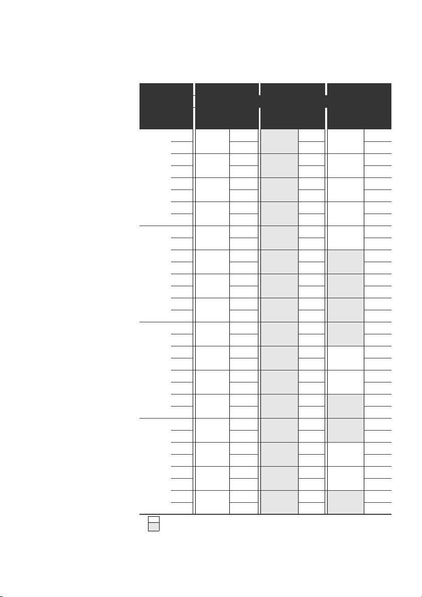
60 AVENTICS | EtherNet/IP™ | R412012728–BDL–001–AC
Commissioning and Operation
Table 15: Examples1) for assignment of switches and valve supply
Example 1 Example 2 Example 3
Double subbase for double solenoid valves
Address
Valve
position
Byte
Switches
S4 0 A0.0 1 14
A0.1 12 – 12
A0.2 2 14
A0.3 12 – 12
A0.4 3 14
A0.5 12 – 12
A0.6 4 14
A0.7 12 – 12
S5 1 A1.0 5 14
A1.1 12 – 12
A1.2 6 14
A1.3 12 – –
A1.4 7 14
A1.5 12 – –
A1.6 8 14
A1.7 12 – –
S6 2 A2.0 9 14
A2.1 12 – –
A2.2 10 14
A2.3 12 – 12
A2.4 11 14
A2.5 12 – 12
A2.6 12 14
A2.7 12 – –
S6 3 A3.0 13 14
A3.1 12 – –
A3.2 14 14
A3.3 12 – 12
A3.4 15 14
A3.5 12 – 12
A3.6 16 14
A3.7 12 – –
1)
White fields indicate valve positions with double solenoid valves.
Fields highlighted in gray indicate valve positions with single solenoid valves.
Sol.
1)
LED
Valve
position
Sol.
2)
LED
Valve
position
Sol.
2)
LED
114114
214214
314314
414414
514514
614614
714714
814814
914914
10 14 10 14
11 14 11 14
12 14 12 14
13 14 914
14 14 10 14
15 14 11 14
16 14 12 14
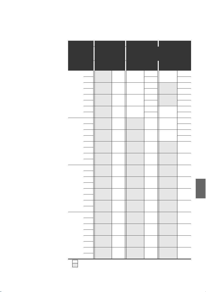
AVENTICS | EtherNet/IP™ | R412012728–BDL–001–AC 61
Commissioning and Operation
Table 16: Examples1) for assignment of switches and valve supply
Example 4 Example 5 Example 6
Double subbase
for single solenoid
Byte
Switches
Address
S4 0 A0.0
A0.1
A0.2
A0.3
A0.4
A0.5
A0.6
A0.7
S5 1 A1.0
A1.1
A1.2
A1.3
A1.4
A1.5
A1.6
A1.7
S6 2 A2.0
A2.1
A2.2
A2.3
A2.4
A2.5
A2.6
A2.7
S6 3 A3.0
A3.1
A3.2
A3.3
A3.4
A3.5
A3.6
A3.7
1)
White fields indicate valve positions with double solenoid valves.
Fields highlighted in gray indicate valve positions with single solenoid valves.
valves
Valve
1)
position
1141 14 114
214 12 12
3142 14 214
414 12 –
5143 14 314
614 12 –
7144 14 414
814 12 12
914514 514
10 14 614 12
11 14 714614
12 14 814 12
13 14 914714
14 14 10 14 814
15 14 11 14 914
16 14 12 14 10 14
17 14 13 14 11 14
18 14 14 14 12 14
19 14 15 14 13 14
20 14 16 14 14 14
21 14 17 14 15 14
22 14 18 14 16 14
23 14 19 14 17 14
24 14 20 14 18 14
25 14 21 14 19 14
26 14 22 14 20 14
27 14 23 14 21 14
28 14 24 14 22 14
29 14 25 14 23 14
30 14 26 14 24 14
31 14 27 14 25 14
32 14 28 14 26 14
Double subbase for single solenoid and
double solenoid valves
Sol.
LED
Valve
position
Sol.
2)
LED
Valve
position
Sol.
2)
LED
English

62 AVENTICS | EtherNet/IP™ | R412012728–BDL–001–AC
Commissioning and Operation
7.2 Configuring the bus coupler
The description in this section refers to the software BOOTP/DHCP Server, Version
2.3.2.0 of Rockwell Automation Inc. The software also contains online documentation
which has to be observed during operation.
The configuration steps laid out in this section are superior to the settings on the bus
coupler which have already been described (see “Making settings” on page 58) and are
a part of the entire system's bus master configuration.
The work described here may only be carried out by qualified electronics
personnel and in compliance with the operator's documentation on configuring
the bus master, as well as applicable technical standards, directives, and safety
regulations.
Before starting configuration, the following steps must have been carried out and
completed on the bus coupler:
W You have assembled the bus coupler and valve terminal
(see “Assembly” on page 51).
W You have connected the bus coupler
(see “Connecting the bus coupler electrically” on page 52).
W You have carried out the presettings (see “Making settings” on page 58).
The configuration may also be carried out using other configuration software,
but the described parameters and settings must be adhered to.
7.2.1 Configuring the bus system
EtherNet/IP™ stands for “Ethernet Industrial Protocol”. To avoid the problems of
a factory-set static IP address, the bus unit is set by default to address assignment using
the DHCP protocol. This is why it is also subject to specifications and limitations when
assigning IP addresses (RFC: 791 INTERNET PROTOCOL; DARPA INTERNET PROGRAM
PROTOCOL SPECIFICATION September 1981). To avoid the problems of a factory-set
static IP address, the bus unit is set by default to address assignment using the
DHCP protocol.
A dynamic or static IP address can then be assigned using the appropriate tool.
Before you start to configure the bus system, consult your network administrator on how
to configure the network. Ask for the values for the subnet mask, gateway, primary DNS,
secondary DNS, and domain name.
To configure the bus system:
1. Start the BOOTP/DHCP server program.
When the program is started for the first time, the network settings must be
adjusted (steps 2 to 4).
2.
In the menu bar, click “Tools” > “Network Settings”.
3. Enter the values for “subnet mask”, “gateway”, “primary DNS”, “secondary DNS”
and “domain name”.
4. Click “OK”.

AVENTICS | EtherNet/IP™ | R412012728–BDL–001–AC 63
Commissioning and Operation
Fig. 7: BOOTP/DHCP server, network settings dialog
The bus coupler sends a DHCP query with its individual hardware address
(MAC address). A line appears in the “Request History” window.
Example: “13:57:39 DHCP 00:04:F3:00:1C:40”
5. Right click on this line.
6. Click “Add to Relation List”.
The “New Entry” window opens.
7. Enter the IP address and confirm with “OK”.
Fig. 8: BOOTP/DHCP server, new entry dialog
The IP address is taken over in the relation list and transferred during the next
query to the respective module. A line appears in the “Request History” window.
Example: “14:00:32 DHCP 00:04:F3:00:1C:40 192.168.0.10”
English
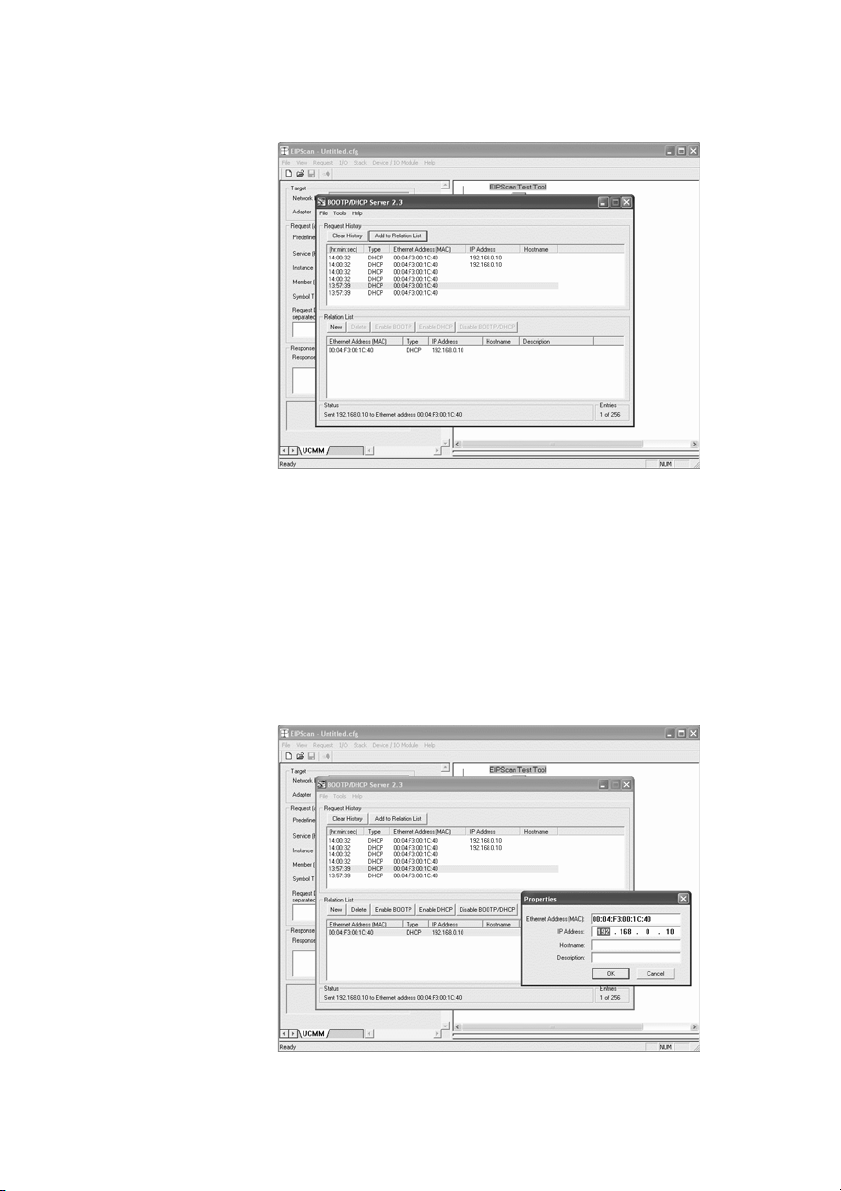
64 AVENTICS | EtherNet/IP™ | R412012728–BDL–001–AC
Commissioning and Operation
Fig. 9: BOOTP/DHCP server, relation list dialog
7.2.2 Saving the address list
You can save the list with “File” > “Save As” so you do not have to manually assign an
IP address to each participant after every program start.
You can load the list with “File” > “Open“ after the next program start.
7.2.3 Change the IP address.
The specified IP address can be changed at any time:
1. Right click on the module in the relation list.
2. Click “Properties”.
3. Enter a new IP address and click “OK”.
The new IP address will be taken over after the next power reset.
Fig. 10: BOOTP/DHCP server, properties dialog

AVENTICS | EtherNet/IP™ | R412012728–BDL–001–AC 65
Commissioning and Operation
7.2.4 Dynamic or static IP address
You can change the currently assigned IP address to a static IP address by clicking the
“Disable BOOTP/DHCP” button. A BOOTP/DHCP server will no longer be needed for
this device during the next system start. If the module is entered in the relation list
and highlighted with a right click, you can reactivate the automatic address
assignment by clicking the “Enable DHCP” button.
7.3 EIP
7.3.1 Configuring the fieldbus module
To be able to address the module from a controller, the module must first be
configured.
In the following example, configuration of a Logix5000 is explained.
1. Start the program RSLogix5000 and the current project.
“Offline” must be selected in the menu as the connection status.
2. Expand the “I/O Configuration” folder in the tree structure and right-click
the “Ethernet” branch.
3. Select “New Module”.
4. Click “ETHERNET-MODULE - Generic Ethernet Module” and confirm with “OK”.
Fig. 11: Select Module dialog window
English

66 AVENTICS | EtherNet/IP™ | R412012728–BDL–001–AC
Commissioning and Operation
5. In the “General” tab, enter the corresponding values in the fields.
Parameter Value
Name: As per project
Comm format: “Data - SINT”
IP Address: As per project
Input:
Assembly Instance: 102
Size: 11 (8-bit)
Output:
Assembly Instance: 100
Size: 10 (8-bit)
Configuration:
Assembly Instance: 1
Size: 0 (8-bit)
Fig. 12: Module Properties: EtherNet_IP dialog window
6. Click the “Connection” tab.
7. In the “Requested Packet Interval (RPI)” field, enter a value ≥ 10 ms and confirm
with “OK”.
The configured device appears under the “Ethernet” branch in the tree structure.
You can check the configuration by selecting the connection status “Go Online”. Any
configuration errors are indicated by means of a yellow exclamation point in the
tree structure.

AVENTICS | EtherNet/IP™ | R412012728–BDL–001–AC 67
Commissioning and Operation
7.3.2 Configuring inputs and outputs
The inputs and outputs can be configured as shown in the following example.
1. In the program RSLogix5000, double click the branch “Controller Tags” under
“Controller Logix5561” in the tree structure.
Different menu groups appear in the right area of the window. The menu group
with the name stored in the configuration (in the example “BDesign”) represents
the valve unit B-Design EthernetIP.
2. Expand the menu group “BDesign:O” by clicking the “+” symbol.
3. Expand the menu group “BDesign:O Data” by clicking the “+” symbol.
The following window appears:
Fig. 13: Controller Tags window area
As soon as you expand the listed bytes (e.g. “BDesign:O.Data[0]”) by clicking the
“+” symbol, the corresponding bits are displayed.
You can view input and diagnostic data by expanding the menu group “BDesign:I”.
Example:
BDesign:I.Data[6] (Module Diagnostics)
Bit Function
0 none <value = 0>
1 none <value = 0>
2Supply voltage for outputs 1-8
3 Supply voltage for outputs 9-16
4 Supply voltage for outputs 17-32
5 Electrical supply voltage for external modules
6 none <value = 0>
7 none <value = 0>
English

68 AVENTICS | EtherNet/IP™ | R412012728–BDL–001–AC
Commissioning and Operation
7.4 Testing and diagnosis on the modules
7.4.1 Reading the bus coupler diagnostic display
The LEDs on the front panel of the bus coupler show the messages from tab. 17.
O Before commissioning and during operation, regularly check bus coupler
functions by reading the diagnostic displays.
LED Signal Description
Supply
(U
Q1/UQ2
U
L
Diagnosis Green No diagnostic message
COMM No function
Connected Green “Unconnected!” or “Class1/3 connection” established
Link Physical Ethernet link established
7.4.2 Check sensors on the input module
There is one LED per input on the input module for monitoring purposes. The LED
lights up if the signal level is high.
O Before commissioning the system, check the sensor function and method of
operation by reading the LEDs.
Green Logic supply available
)
Red Sensor or valve supply overload (group diagnosis)
Green Logic voltage available
Off No logic voltage available (U
Red Diagnostic message present
Red For Class 1/3 connection: PLC in STOP
Valve supply UQ1/UQ2 OK
Low voltage (U
For Class 1/3 connection: PLC in RUN mode
Q1/UQ2
< 18.5 V)
<16V)
L
Fig. 14: LED displays on the M8 input module (left) and M12 (right)
LED Color Meaning
Input Yellow High signal level mode

AVENTICS | EtherNet/IP™ | R412012728–BDL–001–AC 69
O
O
O
O
O
O
O
O
OO
Commissioning and Operation
7.4.3 Check actuators on the output module
O Before commissioning, check the actuator function and the method of operation
using the LED displays on the output module.
Fig. 15: LED displays on the M8 output module (left) and M12 (right)
Table 17: Meaning of the LED displays on the output module
LED Color Meaning
U
Q1
U
Q2
O0 to O7 Off Corresponding LOW level output
Green Load supply UQ1 available
Red Diagnosis: Overload/short circuit of controlled output O0,
O1, O2, or O3
Off Load supply U
Q1 not available (e.g. emergency OFF)
Green Load supply UQ2 available
Red Diagnosis: Overload/short circuit of controlled output O4,
O5, O6, or O7
Off Load supply U
not available (e.g. emergency OFF)
Q2
Yellow Corresponding HIGH level output
English

70 AVENTICS | EtherNet/IP™ | R412012728–BDL–001–AC
Commissioning and Operation
7.5 Commissioning the bus coupler
Before commissioning the system, the following steps must have been carried out
and completed:
W You have assembled the valve terminal and the bus coupler
(see “Assembling the valve system with bus coupler” on page 51).
W You have connected the bus coupler (see “Connec ting the bus coupler electrically”
on page 52).
W You have made the presettings and configured the system (see “Making settings”
on page 58 and “Configuring the bus coupler” on page 62).
W You have configured the bus master so that it controls the valves and the input
module correctly.
W You have carried out the diagnostic test on the input/output modules
(see “Testing and diagnosis on the modules” on page 68).
Commissioning may only be carried out by qualified electrical or pneumatic
personnel or an instructed person under the direction and supervision
of qualified personnel (see “Personnel qualifications” on page 45).
CAUTION
Risk of uncontrolled actuator movements when the pneumatics are switched on
Danger of injury if the system is in an undefined state and the manual overrides
are not set to position “0”.
O
Put the system in a defined state before switching it on.
O Set all manual overrides to position “0”.
O Make sure that no personnel are within the hazardous zone when the pressure
is switched on.
O Also observe the applicable instructions and safety information in the
VS operating instructions.
1. Switch on the operating voltage.
2. Check the LED displays on all modules.
3. Switch on the compressed air supply.

AVENTICS | EtherNet/IP™ | R412012728–BDL–001–AC 71
Disassembly and Exchange
8 Disassembly and Exchange
You can either exchange the bus coupler or connect additional input/output modules
and module extensions as needed.
The AVENTICS warranty only applies to the delivered configuration and
extensions taken into account in the configuration. The warranty no longer
applies after a conversion that exceeds these extensions.
8.1 Exchange the bus coupler
See fig. 16 on page 72.
CAUTION
Applied electric voltage and high pressure!
Danger of injury from electric shock and sudden pressure drops.
O Make sure the system is not under pressure or voltage before you exchange
the modules.
1.
Disconnect the electrical connections from the bus coupler (4).
2. Unscrew the end plate (2) and (if applicable) all input/output modules to the left
of the bus coupler (each with 2 DIN 912 - M4 hexagonal socket-head screws (1),
wrench size 3) and remove from the tie rods (5).
3. Remove bus coupler (4) from the tie rods (5).
4. Push the new bus coupler (4) onto the tie rods (5).
5. Make sure that
–the tie rods (5) have been completely screwed in and
– the seals (3) have been inserted correctly.
6. Push the input/output modules (if applicable) in the original order and then the left
end plate (2) onto the tie rods (5) and screw into place (each with 2 DIN 912 – M4
hexagonal socket-head screws (1), wrench size 3).
Tightening torque: 2.5 to 3.0 Nm.
7. Make all the presettings on the new bus coupler (4)
(see “Making settings” on page 58).
8. Reestablish the connections.
9. Check the configuration and adjust it if necessary
(see “Configuring the bus coupler” on page 62).
English

72 AVENTICS | EtherNet/IP™ | R412012728–BDL–001–AC
4
1
2
3
3
6
5
Disassembly and Exchange
Fig. 16: Exchanging the bus coupler, example
1 Hexagonal socket-head screws 4 Bus coupler
2 End plate left 5 Tie rod
3 Seal 6 Left end plate with connections
8.2 Mounting input/output module(s)
Input and output modules can be added to the valve system. See fig. 17 on page 73.
CAUTION
Applied electric voltage and high pressure!
Danger of injury from electric shock and sudden pressure drops.
O Make sure the system is not under pressure or voltage before you exchange
the modules.
A maximum of 6 modules (input or output) may be mounted on one valve
system. Observe the permissible current load!
1.
Unscrew the left end plate (2) from the bus coupler (7) or from the last input (5)
or output module (
screws (1), wrench size 3) and remove it from the tie rods (
2. Screw the tie rods (6) for the input (5) or output module s (4) on the existing tie rods
(6) (2 per input (5) or output module (4)).
– Ensure that the tie rods (6) are flush with the surface!
4
) of the valve system (2 DIN 912 – M4 hexagonal socket-head
6
).

AVENTICS | EtherNet/IP™ | R412012728–BDL–001–AC 73
6
6
2
3
3
3
4
5
1
7
Disassembly and Exchange
3. Attach the (additional) input (5) or output module (4) to the tie rods (6).
– Make sure the seals (3) have been correctly inserted and that the contacts
have been properly connected.
4. Retighten the left end plate (2) after the last input module (5) or output module (4)
(2 DIN 912 – M4 hexagonal socket-head screws (1), wrench size 3).
Tightening torque: 2.5 to 3 Nm.
5. Establish the pneumatic connections (see “Connecting the bus coupler logic and
load supply” on page 53).
CAUTION
Open inputs/outputs
Danger of electric shocks caused by contact, short circuits, or damage to
the system.
O
Always close unused inputs or outputs with protective caps (see “Spare parts
and accessories” on page 75) to comply with the IP65 protection class.
6. Adjust the configuration (see “Configuring the bus coupler” on page 62).
Fig. 17: Mounting input/output module(s), example
1 Hexagonal socket-head screws 5 Input module
2 End plate left 6 Tie rod
3 Seal 7 Bus coupler
4 Output module
English

74 AVENTICS | EtherNet/IP™ | R412012728–BDL–001–AC
Care and Maintenance
9 Care and Maintenance
CAUTION
Applied electric voltage and high pressure!
Danger of injury from electric shocks and sudden pressure drops.
O Make sure the system is not pressurized or connected to power before
carrying out any service or maintenance work.
9.1 Servicing the modules
NOTICE
Damage to the housing surface caused by solvents and aggressive detergents!
The surfaces and seals could be damaged by solvents or aggressive
cleaning agents.
O Never use solvents or aggressive detergents.
O Regularly clean the device with a damp cloth. Only use water or a mild
cleaning agent.
9.2 Maintaining the modules
The bus coupler and I/O modules for the VS are maintenance-free.
O Comply with the maintenance intervals and specifications for the entire system.
10 Technical Data
10.1 Characteristics
General
Degree of protection according to
EN 60 529/IEC 529
Ambient temperature ϑ
Electromagnetic compatibility
Interference emission EN 61000-6-4
Interference immunity EN 61000-6-2
U
0°C to +50°C, without condensation
IP 65 when assembled

AVENTICS | EtherNet/IP™ | R412012728–BDL–001–AC 75
Spare parts and accessories
10.2 Bus coupler
Electrical
Logic operating voltage U
Load operating voltage
U
, U
Q1
Q2
L
Protective extra-low voltage (SELV/PELV)
24 V DC (+20%/–15%)
24 V DC (±10%),
according to EC 364-4-41,
residual ripple 0.5%
10.3 8x input modules, RMV04-8DI_M8 and
RMV04-8DI_M12
Electrical
Inputs DIN EN 61131-2 8 digital inputs, type 3,
Total current of 24 V sensor supply for all input modules limited to 0.7 A.
Input delay 0 – 1 3 ms
Input delay 1 – 0 3 ms
two-wire proximity switch with a quiescent
current of max. 2.5 mA can be connected
10.4 8x output modules, RMV04-8DO_M8 and
RMV04-8DO_M12
Electrics
Outputs DIN EN 61131-2 8 digital outputs
Output voltage Nominal value 24 V
Output current Nominal value 0.5 A
Overload protection Switches off at 0.6 to 1.2 A
Line length for M8
and M12 connection
Power supply
and U
U
Q1
Q2
For thermal reasons, the outputs may not be
loaded with anything above the nominal current
H signal voltage drop ≤ 1.5 V
for long periods.
Autom. start-up when load is reduced
Max. 30 m
Nominal value 24 V
(+20 %/-15 %)
English
11 Spare parts and accessories
Bus coupler with field bus protocol EtherNet/IP™
Accessories
M12x1 protective cap R419800769
End plate for bus coupler
1)
Delivery incl. 2 tie rods, seal and manual
2)
Delivery incl. 2 mounting screws and 1 seal
2)
1)
Order number
R412012755
R412003490

76 AVENTICS | EtherNet/IP™ | R412012728–BDL–001–AC
Disposal
11.1 8x input/output module, 8DI/8DO
8x input module (8x M8)
8x input module (4x M12)
8x output module (8x M8)
8x output module (4x M12)
Accessories
Straight plug connector, with self-clinching
screw, M8x1, 3-pin
M8x1 protective cap for inputs (delivery unit = 25 pieces)
M12x1 protective cap for inputs (delivery unit = 25 pieces) 182 331 200 1
M12 Y-distributor with M12 self-clinching screw, 5-pin, 2x M12
cable socket, 1x M12 cable plug
1)
Delivery incl. 2 tie rods and 1 seal
1)
1)
1)
1)
11.2 Power plug for bus coupler and output module
Plug connector for voltage supply,
M12×1 socket, 4-pin for cable Ø 4-8 mm,
A-coded
Plug connector for input/output modules M12x1 plug, straight 1 834 484 222
Order code Order number
8DI_M8 R412003489
8DI_M12 R412008040
8DO_M8 R412005968
8DO_M12 R412005968
Cable length
2m
Cable length
5m
Cable length
10 m
o
180
(X10, POWER) 894 105 432 4
o
90
(X10, POWER) 894 105 442 4
M12x1 plug, angled 1 834 484 223
M12x1 dual plug
for cable Ø 3 mm
or 5 mm
894 620 360 2
894 620 361 2
894 620 362 2
R412003493
894 100 239 2
Order number
1 834 484 246
12 Disposal
Dispose of the device in accordance with the currently applicable regulations in
your country.

AVENTICS | EtherNet/IP™ | R412012728–BDL–001–AC 77
13 Index
Index
W A
Abbreviations 6
Assembly
Connecting the 8x I/O
module 17
Electrical connections 14
Mounting options 13
Assembly, FE
connection 19
Assigning the valve
supply 20
W B
Bus coupler
Spare parts,
Accessories 37
Technical data 37
W C
Characteristics 36
Commissioning
Diagnostic display 30
presettings 20
Testing/diagnosis 30
Commissioning,
commissioning 32
Components
Bus coupler 10
Input modules 11
Output modules 12
Configuration
Bus coupler 24
Configuring the bus
system 24
W D
Diagnostic display, Bus
coupler 30
Disposal 38
W E
Electrical connection
Bus coupler 15
FE 19
Input/output modules 17
logic and load supply 15
Electrical connection,
shielding 15
Exchange the bus
coupler 33
W I
Input module technical
data 37
Input/output modules
Assembly 34
Description 11
Spare parts,
accessories 38
W L
Labeling
Bus coupler 13
Input/output modules 13
W O
Output module technical
data 37
W P
Plug connection
English

78 AVENTICS | EtherNet/IP™ | R412012728–BDL–001–AC
Index
X10 (POWER) 15
Power supply
Connection cable 18
Presettings
Assigning the valve
supply 20
W Q
Qualifications and
personnel 7
W S
Safety instructions
Cleaning 8
During assembly 8
During commissioning
and operation 8
General 7
Standards 5, 8
W T
Test and diagnosis
Bus coupler 30
Testing and diagnosis
Input module 30
Output module 31
W U
Use
improper 7
intended 7

AVENTICS | EtherNet/IP™ | R412012728–BDL–001–AC 79
Sommaire
1 A propos de cette documentation .................................... 7
1.1 Documentations nécessaires et complémentaires .............7
1.2 Présentation des informations...................................................7
1.2.1 Consignes de sécurité ................................................................. 7
1.2.2 Symboles ........................................................................................ 8
1.3 Abréviations utilisées....................................................................8
2 Consignes de sécurité ....................................................... 8
2.1 A propos de ce chapitre................................................................8
2.2 Utilisation conforme ......................................................................9
2.3 Utilisation non conforme..............................................................9
2.4 Qualification du personnel...........................................................9
2.5 Consignes générales de sécurité...............................................9
3 Domaines d’application .................................................. 10
4 Fourniture ........................................................................ 10
5 Description de l’appareil ................................................ 11
5.1 Vue d’ensemble de l’îlot de distribution
et des modules..............................................................................11
5.2 Composants ...................................................................................12
5.2.1 Coupleur de bus .......................................................................... 12
5.2.2 Modules d’entrée / de sortie ................................................... 13
5.2.3 Modules d’entrée ........................................................................ 13
5.2.4 Modules de sortie ....................................................................... 14
6 Montage ............................................................................ 15
6.1 Montage de l’îlot de distribution avec coupleur de bus ....15
6.2 Marquage des modules ..............................................................15
6.3 Raccordement électrique du coupleur de bus ....................16
6.3.1 Remarques générales concernant le raccordement du
coupleur de bus .......................................................................... 16
6.3.2 Raccordement du coupleur de bus ....................................... 17
6.3.3 Raccordement de l’alimentation des circuits logiques et
des distributeurs du coupleur de bus .................................. 17
6.3.4 Raccordement des modules d’entrée / de sortie 8x ....... 19
6.3.5 Raccordement de l’alimentation des distributeurs du
module
de sortie ........................................................................................ 20
6.3.6 Raccord FE ................................................................................... 21
Français

80 AVENTICS | EtherNet/IP™ | R412012728–BDL–001–AC
7 Mise en service et utilisation ......................................... 22
7.1 Définition des paramétrages préalables...............................22
7.1.1 Affectation de l’alimentation du distributeur ..................... 22
7.2 Configuration du coupleur de bus...........................................26
7.2.1 Configuration du système bus ................................................ 26
7.2.2 Enregistrement de la liste d’adresses ................................. 28
7.2.3 Modification de l’adresse IP .................................................... 28
7.2.4 Adresse IP statique ou dynamique ....................................... 29
7.3 EIP.....................................................................................................29
7.3.1 Configuration du module bus ................................................. 29
7.3.2 Configuration des entrées et sorties .................................... 31
7.4 Test et diagnostic sur les modules .........................................32
7.4.1 Lecture de l’affichage de diagnostics sur
le coupleur de bus ...................................................................... 32
7.4.2 Vérification des capteurs sur le module d’entrée ............ 32
7.4.3 Vérification des actionneurs sur le module de sortie .... 33
7.5 Mise en service du coupleur de bus .......................................34
8 Démontage et remplacement ......................................... 35
8.1 Remplacement du coupleur de bus........................................35
8.2 Ajout de module(s) d’entrée / de sortie.................................36
9 Entretien et maintenance ............................................... 38
9.1 Entretien des modules................................................................38
9.2 Maintenance des modules.........................................................38
10 Données techniques ........................................................ 38
10.1 Caractéristiques............................................................................38
10.2 Coupleur de bus............................................................................39
10.3 Modules d’entrée 8x, RMV04-8DI_M8 et
RMV04-8DI_M12 ...........................................................................39
10.4 Modules de sortie 8x, RMV04-8DO_M8 et
RMV04-8DO_M12..........................................................................39
11 Pièces de rechange et accessoires ............................... 39
11.1 Modul d’entrée / de sortie 8x, 8DI/8DO..................................40
11.2 Connecteur pour coupleur de bus et module
de sortie...........................................................................................40
12 Elimination des déchets ................................................. 40
13 Index ................................................................................. 41

AVENTICS | EtherNet/IP™ | R412012728–BDL–001–AC 81
A propos de cette documentation
1 A propos de cette documentation
Ce mode d’emploi contient des informations importantes pour installer, utiliser et
entretenir le coupleur de bus de manière sûre et conforme, ainsi que pour pouvoir
éliminer soi-même de simples interférences.
O Lire entièrement cette documentation et en particulier le chapitre 2 « Consignes
de sécurité » à la page 82 avant de travailler avec le coupleur de bus.
1.1 Documentations nécessaires et complémentaires
O Ne mettre le produit en service qu’en possession des documentations suivantes
et qu’après les avoir comprises et observées :
Tableau 1 : Documentations nécessaires et complémentaires
Désignation
Documentation de l’îlot de distribution
HF04 D-SUB
Documentation de l’îlot de distribution
HF03-LG
Documentation de l’îlot de distribution
CD01/02-PI
Documentation de l’extension de module
forme B, Stand Alone
Documentation de l’installation
Pour de plus amples informations concernant les composants, consulter le catalogue
en ligne d’AVENTICS sur le site www.aventics.com/pneumatics-catalog
Numéro du
document
R412015493 Instructions
R412008233 Instructions
R412012449 Instructions
R412008961 Instructions
Type de
document
1.2 Présentation des informations
Afin de pouvoir travailler rapidement et en toute sécurité avec ce produit, cette
documentation contient des consignes de sécurité, symboles, termes et abréviations
standardisés. Ces derniers sont expliqués dans les paragraphes suivants.
1.2.1 Consignes de sécurité
Dans la présente documentation, des consignes de sécurité figurent devant les
instructions dont l’exécution recèle un risque de dommages corporels ou matériels.
Les mesures décrites pour éviter des dangers doivent être respectées.
Les consignes de sécurité sont structurées comme suit :
MOT-CLE
Type et source de danger
Conséquences en cas de non-respect
O Mesure préventive contre le danger
W Signal de danger : attire l’attention sur un danger
W Mot-clé : précise la gravité du danger
W Type et source de danger : désigne le type et la source du danger
W Conséquences : décrit les conséquences en cas de non-respect
W Remède : indique comment contourner le danger
Français

82 AVENTICS | EtherNet/IP™ | R412012728–BDL–001–AC
Consignes de sécurité
Tableau 2 : Classes de dangers selon la norme ANSI Z535.6-2006
Signal de danger, mot-clé Signification
Signale une situation dangereuse susceptible
ATTENTION
REMARQUE
d’entraîner des blessures légères à modérées
si le danger n’est pas évité.
Dommages matériels : le produit ou son
environnement peuvent être endommagés.
1.2.2 Symboles
Les symboles suivants signalent des consignes qui ne relèvent pas de la sécurité
mais améliorent néanmoins l’intelligibilité de la documentation.
Tableau 3 : Signification des symboles
Symbole Signification
En cas de non-respect de cette information, le produit ne livrera pas
sa performance optimale.
O Action isolée et indépendante
1.
2.
3.
Consignes numérotées :
Les chiffres indiquent l’ordre des différentes actions.
1.3 Abréviations utilisées
Tableau 4 : Abréviations utilisées
Abréviation Signification
VS Ilot de distribution
EIP Ethernet/IP™
EDS Données de base de l’appareil
2 Consignes de sécurité
2.1 A propos de ce chapitre
Le produit a été fabriqué selon les règles techniques généralement reconnues.
Des dommages matériels et corporels peuvent néanmoins survenir si ce chapitre
de même que les consignes de sécurité ne sont pas respectés.
O Lire la présente documentation attentivement et complètement avant d’utiliser
le produit.
O Conserver cette documentation de sorte que tous les utilisateurs puissent
y accéder à tout moment.
O Toujours transmettre le produit à de tierces personnes accompagné des
documentations nécessaires.

AVENTICS | EtherNet/IP™ | R412012728–BDL–001–AC 83
Consignes de sécurité
2.2 Utilisation conforme
O Employer le coupleur de bus uniquement dans le domaine industriel.
O Respecter les limites de puissance indiquées dans les données techniques.
L’utilisation conforme inclut le fait d’avoir lu et compris cette documentation dans son
intégralité et en particulier le chapitre « Consignes de sécurité ».
2.3 Utilisation non conforme
Toute autre utilisation que celle décrite au chapitre « Utilisation conforme » est
non conforme et par conséquent interdite.
En cas de pose ou d’utilisation de produits inadaptés dans des applications qui
relèvent de la sécurité, des états d’exploitation incontrôlés peuvent survenir dans ces
applications et entraîner des dommages corporels et/ou matériels. Par conséquent,
utiliser des produits dans des applications qui relèvent de la sécurité uniquement
lorsque ces applications sont expressément spécifiées et autorisées dans la
documentation. AVENTICS GmbH décline toute responsabilité en cas de dommages
résultant d’une utilisation non conforme. Toute utilisation non conforme est aux
risques et périls de l’utilisateur.
Une utilisation non conforme du coupleur de bus correspond
W
à une utilisation en dehors des domaines d’application cités dans ce mode d’emploi
W une utilisation déviant des conditions de fonctionnement décrites dans ce mode
d’emploi.
2.4 Qualification du personnel
Les opérations décrites dans cette documentation exigent des connaissances
électriques et pneumatiques de base, ainsi que la connaissance des termes
techniques qui y sont liés. Afin d’assurer une utilisation en toute sécurité, ces travaux
ne doivent par conséquent être effectués que par des professionnels spécialement
formés ou par une personne instruite et sous la direction d’un spécialiste.
Une personne spécialisée est capable de juger des travaux qui lui sont confiés, de
reconnaître d’éventuels dangers et de prendre les mesures de sécurité adéquates
grâce à sa formation spécialisée, ses connaissances et expériences, ainsi qu’à ses
connaissances des directives correspondantes. Elle doit respecter les règles
spécifiques correspondantes.
2.5 Consignes générales de sécurité
W Respecter les consignes de prévention d’accidents et de protection de
l’environnement dans le pays d’utilisation et au poste de travail.
W En règle générale, ne pas modifier ni transformer l’appareil.
W
Utiliser l’appareil uniquement dans le champ de travail indiqué dans les données
techniques.
W Ne surcharger en aucun cas l’appareil de manière mécanique. Ne jamais
y déposer d’objets.
W
Utiliser cet appareil uniquement dans le domaine industriel (classe A). Pour les
installations devant être utilisées dans les espaces de séjour (habitations, bureaux
et sites de production), demander une autorisation individuelle auprès d’une
administration ou d’un office de contrôle. En Allemagne, de telles régulations sont
délivrées par la Regulierungsbehörde für Telekommunikation und Post
(administration de régulation des Postes et Télécommunications, RegTP).
W S’assurer que l’alimentation électrique se situe dans la plage de tolérance
indiquée pour les modules.
W Respecter les consignes de sécurité figurant dans le mode d’emploi de l’îlot
de distribution.
Français

84 AVENTICS | EtherNet/IP™ | R412012728–BDL–001–AC
Domaines d’application
W
Tous les composants sont alimentés par un bloc d’alimentation à 24 V. Le bloc
d’alimentation doit être équipé d’une mise hors service de sécurité conformément
à la norme EN 60742, classification VDE 0551. Les composants de circuit
correspondants sont donc valables en tant que composants de circuit SELV /
PELV selon CEI 60364-4-41.
W Débrancher la tension de service avant de brancher ou débrancher des
connecteurs.
W
Lors du montage
Lors de la mise en service
Lors du fonctionnement
Lors du nettoyage
La garantie est uniquement valable pour la configuration livrée. Elle n’est plus valable
en cas de montage incorrect.
W Mettre la partie concernée de l’installation hors tension et hors pression avant de
monter l’appareil ou de le démonter. Veiller à protéger l’installation contre toute
remise en marche pendant les travaux de montage.
W Mettre les modules et l’îlot de distribution à la terre. Lors de l’installation du
système, respecter les normes suivantes :
– DIN EN 50178, classification VDE 0160
– VDE 0100
W L’installation ne doit avoir lieu qu’en l’absence de toute tension et de toute
pression et n’être effectuée que par un personnel qualifié et expérimenté.
N’effectuer la mise en service électrique qu’en l’absence de toute pression
afin d’éviter tout mouvement dangereux des actionneurs.
W Ne mettre le système en service que lorsqu’il est complètement monté,
correctement câblé et configuré, et après l’avoir testé.
W L’appareil est soumis à l’indice de protection IP 65. Avant la mise en service,
s’assurer que tous les joints et bouchons des raccords enfichables sont étanches,
afin d’éviter que des liquides ou des corps solides ne pénètrent dans l’appareil.
W Assurer une aération ou un refroidissement suffisant lorsque l’îlot de distribution
présente les caractéristiques suivantes :
– Equipement complet
– Sollicitation continue des bobines
W Ne jamais utiliser des solvants ou des détergents agressifs. Nettoyer l’appareil
uniquement avec un chiffon légèrement humide. Pour cela, utiliser exclusivement
de l’eau et éventuellement un détergent doux.
3 Domaines d’application
Le coupleur de bus sert à la commande électrique des distributeurs via le système
bus Ethernet/IP™. Les modules d’entrée / de sortie offrent en outre la possibilité
de relier des signaux électriques d’entrée et de sortie par la connexion bus de l’îlot
de distribution.
Le coupleur de bus est exclusivement destiné à fonctionner en tant qu’esclave dans
un système bus Ethernet/IP™ selon la norme EN 50170, partie 2.
4 Fourniture
La fourniture d’un îlot de distribution configuré comprend :
W 1 îlot de distribution conformément à la configuration et à la commande
W 1 mode d’emploi de l’îlot de distribution
W 1 mode d’emploi du coupleur de bus
La fourniture d’un jeu de pièces pour un coupleur de bus comprend :
W
1 coupleur de bus avec joint et deux tirants
W 1 mode d’emploi
Le VS est configuré individuellement. La configuration exacte peut être affichée
à l’aide du numéro de référence dans le configurateur Internet d’AVENTICS.
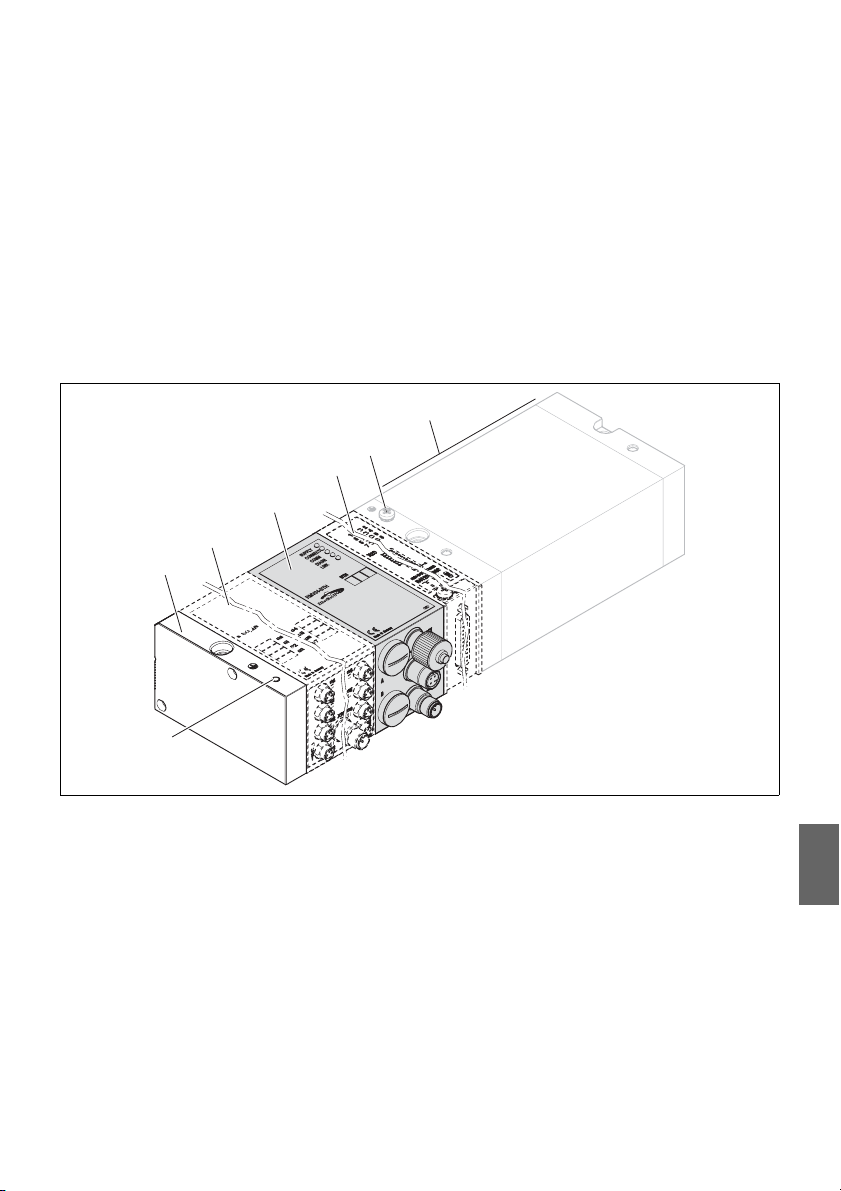
AVENTICS | EtherNet/IP™ | R412012728–BDL–001–AC 85
1
2
3
4
6
7
5
Description de l’appareil
5 Description de l’appareil
Le coupleur de bus permet de commander le VS par le biais d’un système bus
Ethernet/IP™. Outre le raccordement des lignes de transmission et des alimentations
électriques, le coupleur de bus permet le réglage de différents paramètres de bus
ainsi que le diagnostic via des LED et le protocole Ethernet/IP™.
La vue d’ensemble suivante offre un aperçu de l’îlot de distribution et de ses
composants. Le VS lui-même est décrit dans un mode d’emploi à part.
5.1 Vue d’ensemble de l’îlot de distribution
et des modules
Selon la commande, l’îlot de distribution est constitué des composants représentés
à la fig. 1 :
Fig. 1 : Vue d’ensemble du coupleur de bus avec modules E/S et porte-distributeurs (exemple de configuration)
1 Plaque terminale à gauche
2 Module de sortie
3 Coupleur de bus, type design B
4 Extension de module, design B, Stand Alone
1)
2)
3)
Jusqu’à 6 modules max. (modules d’entrée ou de sortie) peuvent être raccordés de manière indifférente
(par ex. 3 modules d’entrée et 3 modules de sortie).
Mode d’emploi à part
Jusqu’à 3 modules (extensions de module) peuvent être intégrés de manière indifférente.
1)
ou module d’entrée
1)
2)3)
5 Raccord FE
6 Porte-distributeurs
7 Raccord FE alternatif en déplaçant la vis de (5)
2)
Français

86 AVENTICS | EtherNet/IP™ | R412012728–BDL–001–AC
1
2
3
4
5
6
7
Description de l’appareil
5.2 Composants
5.2.1 Coupleur de bus
Fig. 2 : Vue d’ensemble du coupleur de bus
1 Affichages DEL pour notifications de diagnostic
2 Case d’inscription BTN
3 X71 (interface de service optionnelle (RS232))
4
Connexion X72 (BUS) destinée à la commande des distributeurs et des modules E/S
5 Connexion X10 (POWER) pour l’alimentation électrique des bobines de distributeurs, du circuit logique et des entrées
6 Capuchon de protection B pour commutateurs à coulisse S4, S5, S6
(assignation des distributeurs pour la tension d’alimentation)
7 Capuchon de protection A pour commutateurs rotatifs S1 et S2 (sans fonction)
et commutateur DIP S3 (sans fonction)
Nombre de distributeurs
pouvant être commandés
Diagnostic
Le coupleur de bus est exclusivement destiné à fonctionner en tant qu’esclave dans
un système bus Ethernet/IP™ basé sur le profil standard de transmission IEEE 802.3.
Le mod ule s e rac cord e à un cont acte ur ou directement à une commande par un câble
conforme aux spécifications Ethernet/IP™.
Les tensions d’alimentation pour les circuits logiques et la commande de distributeur
sont surveillées. Si les limites ne sont pas atteintes ou si elles sont dépassées, un signal
d’erreur est alors généré et signalé grâce à une LED de diagnostic et à l’information
de diagnostic.
Il est possible de commander au maximum 16 distributeurs bistables ou 32 distributeurs
monostables ou une combinaison correspondante de distributeurs bistables et
monostables. Dans tous les cas, un maximum de 32 bobines de distributeurs peut
être commandé.

Nombre de modules
2
3
1
2
3
1
pouvant être raccordés
AVENTICS | EtherNet/IP™ | R412012728–BDL–001–AC 87
Description de l’appareil
5.2.2 Modules d’entrée / de sortie
Grâce aux raccords enfichables amovibles, les modules d’entrée / de sortie offrent la
possibilité d’émettre des signaux électriques d’entrée et de sortie par la connexion
bus de l’îlot de distribution.
Des modules d’entrée et de sortie peuvent être branchés de manière indifférente à l’îlot
de distribution avec coupleur de bus – en tout 6 modules max. L’ordre ici n’a aucune
importance.
O Veiller à respecter les limites de charge !
Le coupleur de bus alimente les entrées des modules d’entrée. La somme des
intensités maximale pour toutes les entrées est de 0,7 A.
Le module de sortie est alimenté par un connecteur M12 avec une alimentation
électrique chacune pour 4 sorties (voir tableau 13 à la page 95).
5.2.3 Modules d’entrée
Les modules d’entrée destinés à la connexion des signaux électriques de capteurs
sont disponibles en deux versions.
W 8 x M8 (RMV04-8DI_M8) ou
W 4 x M12, double affectation (RMV04-8DI_M12)
Fig. 3 : Module d’entrée 8x : RMV04-8DI_M8 (à gauche) et RMV04-8DI_M12 (à droite)
1 Case d’inscription
2 RMV04-8DI_M8 : 8 entrées, 8DI_M8
RMV04-8DI_M12 : 4 entrées, 8DI_M12, double affectation
3 Affichage DEL (jaune, état) par entrée
Français

88 AVENTICS | EtherNet/IP™ | R412012728–BDL–001–AC
1
2
3
4
6
5
1
2
3
45
6
Description de l’appareil
5.2.4 Modules de sortie
Les modules de sortie destinés à la connexion des actionneurs sont disponibles en
deux versions :
W 8 x M8 (RMV04-8DO_M8) ou
W 4 x M12, double affectation (RMV04-8DO_M12)
Fig. 4 : Module de sortie 8x : RMV04-8DO_M8 (à gauche) et RMV04-8DO_M12 (à droite)
1 Case d’inscription
2 Affichage DEL (jaune, état) par sortie
3 Affichage DEL bicolore, alimentation des distributeurs U
4 Raccordement d’alimentation des distributeurs via connecteur M12
5 RMV04-8DO_M8 : 8 sorties, 8DO_M8
RMV04-8DO_M12 : 4 sorties, 8DO_M12, double affectation
6 Affichage DEL bicolore, alimentation des distributeurs U
Q2
Q1

Coupleur de bus
Modules d’entrée / de sortie
AVENTICS | EtherNet/IP™ | R412012728–BDL–001–AC 89
Montage
6 Montage
6.1 Montage de l’îlot de distribution avec coupleur
de bus
L’îlot de distribution est livré individuellement configuré, complètement vissé avec
tous les composants :
W Porte-distributeurs
W Coupleur de bus
W Jusqu’à six modules E/S, le cas échéant
W Jusqu’à trois extensions de module, le cas échéant
Le montage de l’ensemble de l’îlot de distribution est décrit dans le manuel
d’utilisation fourni avec le VS. La position de montage du VS monté est indifférente.
Les dimensions du VS complet varient en fonction de l’équipement en modules.
6.2 Marquage des modules
O Inscrire l’adresse prévue / utilisée pour le coupleur de bus dans le champ BTN sur
le coupleur de bus.
O Inscrire les raccordements directement sur les cases d’inscription des modules
d’entrées / de sortie.
L’affectation des champs d’inscription aux raccordements est donnée par la
description des raccordements.
Fig. 5 : Cases d’inscription sur le coupleur de bus (CMS-B-BEIP), module d’entrée
(8DI_M8) et module de sortie (8DO_M8), exemples
Français

90 AVENTICS | EtherNet/IP™ | R412012728–BDL–001–AC
Montage
6.3 Raccordement électrique du coupleur de bus
ATTENTION
Tension électrique présente
Risque de blessure par décharge électrique.
O Toujours mettre la partie concernée de l’installation hors tension et hors
pression, avant de procéder au raccordement électrique des modules sur le
porte-distributeurs.
REMARQUE
Câblage erroné
Un câblage erroné ou défectueux provoque des dysfonctionnements ou des
dommages au réseau.
O Respecter – sauf indication contraire – la directive Network Infrastructure for
Ethernet/IP™ Publication Number: PUB00035R0.
O Veiller à utiliser uniquement des câbles correspondant aux spécifications bus
et répondant aux exigences de vitesse et de longueur de la connexion.
O Monter les câbles et connecteurs selon les instructions de montage, afin
d’assurer l’indice de protection et la décharge de traction.
REMARQUE
Courant électrique dans le blindage dû à des différences de potentiel
Aucun courant compensateur, dû à des différences de potentiel, ne doit passer via
le blindage du câble bus, car le blindage est ainsi supprimé et les câbles ainsi que
le coupleur de bus branché peuvent être endommagés.
O
Relier, le cas échéant, les points de mesure de l’installation par un câble séparé.
6.3.1 Remarques générales concernant le raccordement du coupleur de bus
Pour raccorder les modules, utiliser des raccords enfichables et des câbles
confectionnés.
O Lors de l’utilisation de raccords enfichables et de câbles non confectionnés,
respecter l’affectation des broches représentée dans le tableau 5.
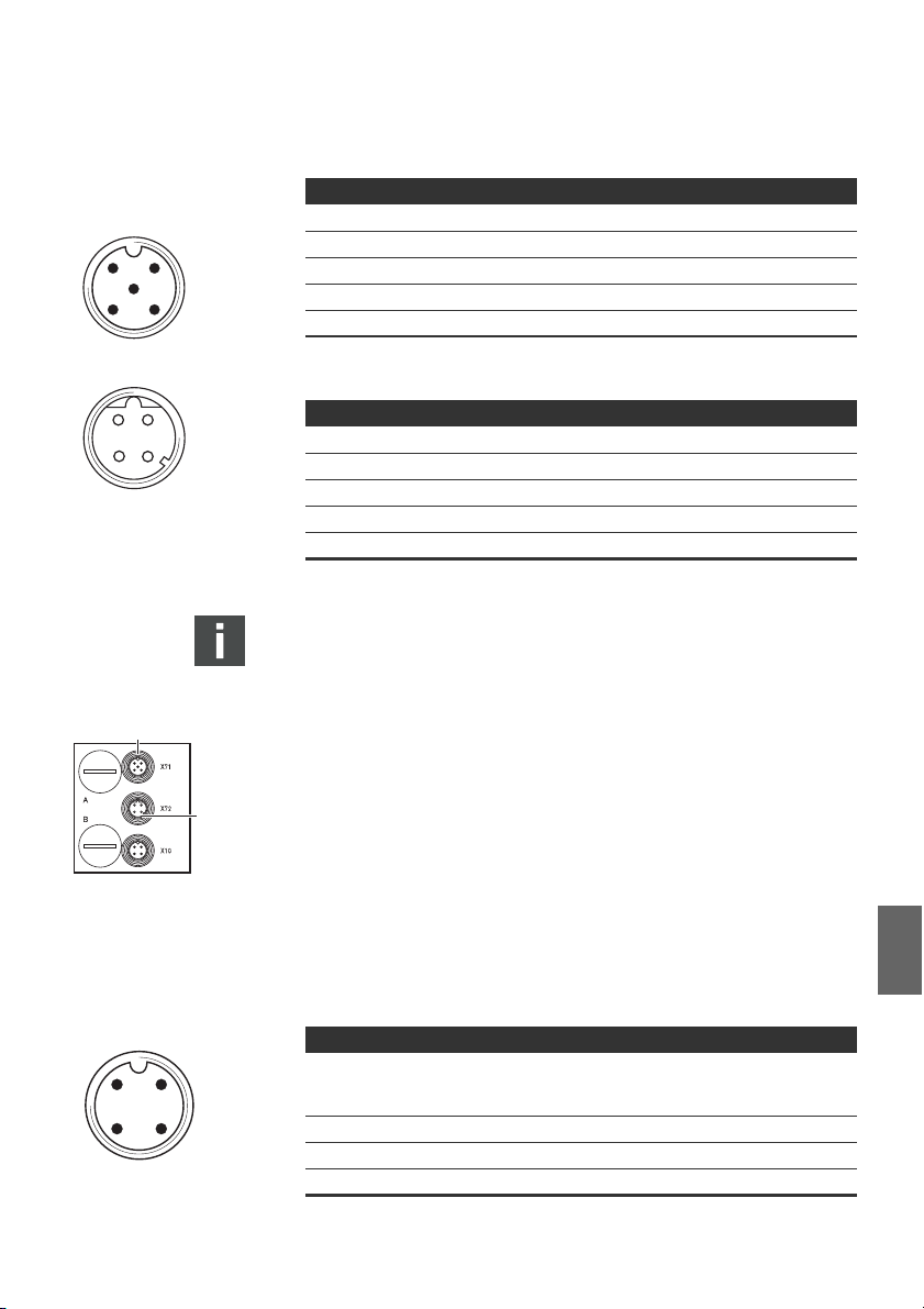
2
1
43
5
2
3
4
1
BUS X72
1
2
AVENTICS | EtherNet/IP™ | R412012728–BDL–001–AC 91
Montage
Tableau 5 : Affectation des broches X71 (RS232), M12, à 5 pôles
Broche Signal Signification
1 nc Non raccordée
2 nc Non raccordée
3 RXD Données de réception
4 GND Potentiel de référence à 0 V
5 TXD Données d’émission
Tableau 6 : Affectation X72 (BUS), M12, codage D
Broche Signal Signification
1 TD+ Transmit pos.
2RD+ Receive pos.
3TD- Transmit neg.
4RD- Receive neg.
1 TD+ Transmit pos.
La connectique et l’affectation des connecteurs correspondent aux directives
de la directive technique Network Infrastructure for Ethernet/IP™ Publication
Number: PUB00035R0.
6.3.2 Raccordement du coupleur de bus
1. En cas d’utilisation de câbles non confectionnés, effectuer l’affectation correcte
des broches (voir le tableau 6 à la page 91) des raccords enfichables.
2. Raccorder le câble bus arrivant à X72 (1) et relier le module à un hub ou à un
switch si d’autres participants doivent être raccordés.
3. Recouvrir la prise X71 (2) d’un capuchon de protection.
4. En cas d’utilisation de câbles non confectionnés et de connecteurs avec boîtier
métallique, raccorder le blindage directement sur le boîtier du connecteur (boîtier
CEM) aux deux côtés du câble bus. Cela permet de protéger les câbles de données
contre les parasites.
6.3.3 Raccordement de l’alimentation des circuits logiques et des distributeurs du coupleur de bus
Les distributeurs et le coupleur de bus sont alimentés par le connecteur
Lors du raccordement de l’alimentation du circuit logique et des distributeurs du
coupleur de bus, respecter l’affectation des broches représentée dans le tableau 7.
POW ER
X10
2
1
43
Tableau 7 : Affectation du connecteur X10 (POWER), M12, codage A
Broche X10 Affectation
1U
Alimentation électrique du circuit logique du coupleur
L
de bus et alimentation du capteur des modules d’entrée
numériques
2U
3 OV Masse pour U
Première alimentation électrique des distributeurs
Q1
et U
L, UQ1
Q2
4UQ2Deuxième alimentation électrique des distributeurs
X10 (POWER)
.
Français
92 AVENTICS | EtherNet/IP™ | R412012728–BDL–001–AC
Montage
W UL, UQ1 et UQ2 sont reliés entre eux de façon galvanique.
W Il est possible d’alimenter les distributeurs par l’alimentation de distributeurs
U
et U
de façon groupée.
Q1
W L’affectation des groupes de distributeurs (4 ou 8 distributeurs) s’effectue par
Le câble pour l’alimentation des distributeurs doit répondre aux exigences suivantes :
W
W Section de câble : chaque fil > 0,5 mm2
W Longueur : max. 20 m
Tableau 8 : Puissance absorbée à X10 (POWER) sur le coupleur de bus
Signal Affectation Courant cumulé
U
U
U
L’alimentation 24 V peut s’effectuer par un bloc d’alimentation commun.
Q2
l’intermédiaire des commutateurs à coulisse S4, S5 et S6 (voir « Affectation de
l’alimentation du distributeur » à la page 96). Ainsi par exemple, une déconnexion
avant ou après l’ARRET D’URGENCE est possible.
Douille de câble : 4 pôles, codage A sans trou central
L
Q1
Q2
Circuit logique et entrées max. 1 A
Distributeurs max. 1 A
Distributeurs max. 1 A
ATTENTION
Tensions dangereuses
Un bloc d’alimentation dont la séparation n’est pas sûre peut provoquer, en cas de
défaut, des tensions dangereuses. Il peut en résulter des blessures par décharge
électrique et un endommagement du système.
O Utiliser uniquement un bloc d’alimentation équipé d’une mise hors service de
sécurité conforme à EN 60747, classification VDE 0551 ! Les composants de
circuit correspondants sont donc valables en tant que composants de circuit
SELV / PELV selon CEI 60364-4-41.
Pour raccorder l’alimentation des distributeurs du coupleur de bus, procéder
comme suit :
1. En cas d’utilisation de câbles non confectionnés, effectuer l’affectation correcte
des broches (voir le tableau 7 à la page 91) des raccords enfichables.
2. Raccorder les tensions de service au coupleur de bus à l’aide du raccord
enfichable (voir « Pièces de rechange et accessoires » à la page 113).
3.
Contrôler et respecter les spécifications des tensions de service en fonction des
caractéristiques électriques (voir chapitre « Données techniques » à la page 112).
4. Préparer les câbles conformément au tableau 8, page 92. Sélectionner les
sections de câble en fonction des longueurs de câble et des courants émergents.

AVENTICS | EtherNet/IP™ | R412012728–BDL–001–AC 93
4
31
I0…I7
2
3
4
1
5
6.3.4 Raccordement des modules d’entrée / de sortie 8x
ATTENTION
Pièces conductrices de courant librement accessibles
Danger de décharge électrique par contact !
O
Lors du raccordement de la périphérie (interface E/S), respecter les exigences
de la protection contre les contacts conformément à la norme EN50178,
classification VDE0160.
Montage
Module d’entrée
1. Câbler les entrées conformément au tableau 9 (DI8_M8) ou au tableau 10
(DI8_M12).
2. Raccorder les entrées / sorties électriques au modules E/S à l’aide de
connecteurs M8 ou M12 (accessoires).
3. Fermer les prises non occupées avec le capuchon de protection M8 ou M12
(accessoires) afin de garantir l’indice de protection IP 65.
La somme des intensités de toutes les alimentations de capteur (broche 1)
à un îlot de distribution ne doit pas dépasser 0,7 A.
Tableau 9 : Affectation des entrées pour le module d’entrée 8x, DI8_M8,
Broche Signal Affectation
1 CAPTEUR+ Alimentation des capteurs +
3 CAPTEUR– Potentiel de référence
4 I0 à I7 Signal capteur
Boîtier Situé sur le potentiel de blindage
Tableau 10 : Affectation des entrées pour le module d’entrée 8x, DI8_M12,
Broche Signal Affectation
1CAPTEUR+
2 I1, I3, I5 ou I7 Signal capteur
3 CAPTEUR– Potentiel de référence GND
4 I0, I2, I4 ou I6 Signal capteur
5 nc Non affectée
Boîtier Situé sur le potentiel de blindage
douille M8x1
douille M12x1
Alimentation capteur + 24 V
Français
Module de sortie
1. Câbler les sorties conformément au tableau 11 (DO8_M8) ou au tableau 12
(DO8_M12).
2. Raccorder les entrées / sorties électriques au modules E/S à l’aide de
connecteurs M8 ou M12 (accessoires).
3. Fermer les prises non occupées avec le capuchon de protection M8 ou M12
(accessoires) afin de garantir l’indice de protection IP65.

94 AVENTICS | EtherNet/IP™ | R412012728–BDL–001–AC
4
31
O0…O7
2
3
4
1
5
Montage
Tableau 11 : Affectation des sorties pour le module de sortie 8x, DO8_M8,
Broche Signal Affectation
1 Libre Non affectée
4 Ox Signal de sortie Ox
3 GND Référence GND de l’actionneur
Boîtier Situé sur le potentiel de blindage
Tableau 12 : Affectation des sorties pour le module de sortie 8x, DO8_M12,
Broche Signal Affectation
1 nc Non affectée
2 O1, O3, O5 ou O7 Signal de sortie
3 GND Potentiel de référence
4 O0, O2, O4 ou O6 Signal de sortie
5 nc Non affectée
Boîtier Situé sur le potentiel de blindage
douille M8x1
(tension nominale 24 V)
douille M12x1
REMARQUE
Somme des intensités trop élevée
Chaque sortie est prévue pour un courant permanent de maximum 0,5 A.
Des charges électriques supérieures à 0,5 A par sortie peuvent endommager
le système.
O Veiller à ce que la charge électrique ne soit pas supérieure à 0,5 A par sortie.
6.3.5 Raccordement de l’alimentation des distributeurs du module de sortie
Chaque module de sortie possède un raccordement M12 propre pour l’alimentation
des distributeurs. Quatre sorties sont à chaque fois alimentées via une tension de
décharge. Les tensions U
Le câble de connexion pour l’alimentation des distributeurs doit répondre aux
exigences suivantes :
W Douille de câble : M12×1, à 4 pôles, codage A sans trou central (protection contre
l’inversion de polarité)
W Section de câble : chaque fil >
W Longueur : max. 20 m
1. En cas d’utilisation de câbles non confectionnés, effectuer l’affectation correcte
des broches (voir le tableau 13) des raccords enfichables.
2. Raccorder l’alimentation des distributeurs à l’aide du connecteur M12.
et UQ2 sont séparées l’une de l’autre galvaniquement.
Q1
0,5 mm2

AVENTICS | EtherNet/IP™ | R412012728–BDL–001–AC 95
2
1
43
POW ER
X10
2
1
Montage
Tableau 13 : Affectation de l’alimentation des distributeurs pour le module de sortie 8x,
Broche X10 Affectation
10V_U
224V_U
30V_U
424V_U
DO8, M12x1, codage A
Q2
Q1
Référence GND pour la tension d’alimentation 2
Tension d’alimentation 1 24 V pour sorties O0 à O3
Q1
Référence GND pour la tension d’alimentation 1
Tension d’alimentation 2 24 V pour sorties O4 à O7
Q2
6.3.6 Raccord FE
O Pour dissiper les interférences CEM, relier le raccord FE (2) à la mise à la terre sur
la plaque terminale gauche par un circuit à basse impédance. Section de câble
conseillée : 10 mm
2
ATTENTION
En cas d’extensions de module (optionnelles) : mise à la terre incomplète
En cas d’utilisation d’extensions de module, la mise à la terre du raccord FE (2)
est insuffisante en raison du boîtier en plastique de ces extensions.
O
En cas d’utilisation d’extensions de module, relier le raccord FE de chaque
extension de module
impédance.
O Pour dissiper les interférences CEM concernant les blocs de distributeurs HF04/
HF04XF, relier le raccord FE (1) au bloc de distributeurs à la mise à la terre par un
câble à basse impédance.
en complément
à la mise à la terre via un câble de basse
Français

96 AVENTICS | EtherNet/IP™ | R412012728–BDL–001–AC
B
A
Mise en service et utilisation
7 Mise en service et utilisation
7.1 Définition des paramétrages préalables
Effectuer les paramétrages préalables suivants :
W Affectation de l’alimentation du distributeur
7.1.1 Affectation de l’alimentation du distributeur
Les commutateurs S4, S5 et S6 destinés à l’affectation de l’alimentation des
distributeurs se trouvent sous le vissage B (voir fig. 6). A chaque commutateur
sont affectées :
W 4 embases doubles pour distributeurs bistables (avec bobines 12 et 14) ou
W 8 embases doubles pour distributeurs monostables (avec bobine 14).
S6
S5
S4
U
Q1UQ2
Fig. 6 : Commutateurs S4, S5, S6 destinés à l’affectation des tensions
Ces commutateurs permettent d’affecter les distributeurs par groupes aux tensions
d’alimentation U
Tous les distributeurs sont affectés à la tension U
Tableau 14 : Affectation des commutateurs S4, S5 et S6
d’alimentation des distributeurs (U
et UQ2.
Q1
Commutateur Octet
S4 0 1 – 4 1 – 8
S5 1 5 – 8 9 – 16
S6 2, 3 09 – 16 17 – 32
Embases doubles pour
distributeurs bistables
(bobines 12 et 14)
Q1
, UQ2)
Q1
à leur livraison.
Embases doubles pour
distributeurs monostables
(bobine 14)
REMARQUE
Tension aux commutateurs
Les commutateurs peuvent être endommagés, lorsqu’une tension est présente
lors de leur utilisation.
O
Actionner les commutateurs uniquement lorsqu’ils sont hors tension !

AVENTICS | EtherNet/IP™ | R412012728–BDL–001–AC 97
Mise en service et utilisation
Pour affecter l’alimentation des distributeurs :
1. Ouvrir le capuchon fileté inférieur B (voir fig. 6 à la page 96).
2. A l’aide des commutateurs S4, S5 et S6, attribuer à chaque groupe
de distributeurs une des deux tensions d’alimentation U
(voir fig. 6 et tableau 14 à la page 96).
Ci-après sont présentés des exemples pour l’affectation des commutateurs S4, S5
et S6 et de l’alimentation de distributeurs montés, dans le tableau 15 à la page 98
(exemples 1 à 3) et le tableau 16 à la page 99 (exemples 4 à 6). Les combinaisons
suivantes y sont représentées :
Exemples
1)
Embases doubles utilisées2)
3)
Exemple 1 Embases doubles pour
distributeurs bistables
Exemple 2 Embases doubles pour
distributeurs bistables
Exemple 3 Embases doubles pour
distributeurs bistables
Exemple 4 Embases doubles pour
distributeurs monostables
Exemple 5 Embases doubles pour
distributeurs bistables
combiné avec
Embases doubles pour
distributeurs monostables
Exemple 6 Embases doubles pour
distributeurs bistables
combiné avec
Embases doubles pour
distributeurs monostables
1)
Ces exemples ne sont valables que lorsqu’aucune extension de module n’est installée.
Suivant les exigences, il est également possible de sélectionner d’autres combinaisons.
2)
D’un point de vue électrique, il faut d’abord disposer les embases doubles pour les
distributeurs bistables, puis ensuite celles pour les distributeurs monostables.
3)
Le nombre de bobines maximal pour toutes les embases est de 32.
ou UQ2
Q1
Equipement des
distributeurs
Distributeurs bistables
Distributeurs
monostables
Distributeurs monostables
et bistables
Distributeurs
monostables
Distributeurs bistables
Distributeurs
monostables
Distributeurs monostables
et bistables
Distributeurs monostables
Français

98 AVENTICS | EtherNet/IP™ | R412012728–BDL–001–AC
Mise en service et utilisation
Tableau 15 : Exemples1) pour l’affectation de commutateurs et l’alimentation
des distributeurs
Exemple 1 Exemple 2 Exemple 3
Embase double pour distributeurs bistables
Octet
Adresse
Empl.
distrib.
Bobine
1)
LED
Empl.
distrib.
Bobine
2)
LED
Empl.
distrib.
2)
Commutateur
S4 0 A0.0 1 14
114114
A0.1 12 – 12
A0.2 2 14
214214
A0.3 12 – 12
A0.4 3 14
314314
A0.5 12 – 12
A0.6 4 14
414414
A0.7 12 – 12
S5 1 A1.0 5 14
514514
A1.1 12 – 12
A1.2 6 14
614614
A1.3 12 – –
A1.4 7 14
714714
A1.5 12 – –
A1.6 8 14
814814
A1.7 12 – –
S6 2 A2.0 9 14
914914
A2.1 12 – –
A2.2 10 14
10 14 10 14
A2.3 12 – 12
A2.4 11 14
11 14 11 14
A2.5 12 – 12
A2.6 12 14
12 14 12 14
A2.7 12 – –
S6 3 A3.0 13 14
13 14 914
A3.1 12 – –
A3.2 14 14
14 14 10 14
A3.3 12 – 12
A3.4 15 14
15 14 11 14
A3.5 12 – 12
A3.6 16 14
16 14 12 14
A3.7 12 – –
1)
Les champs blancs signalent des emplacements de distributeurs avec distributeurs bistables.
Les champs grisés signalent des emplacements de distributeurs avec distributeurs
monostables.
Bobine
LED

AVENTICS | EtherNet/IP™ | R412012728–BDL–001–AC 99
Mise en service et utilisation
Tableau 16 : Exemples1) pour l’affectation de commutateurs et l’alimentation
des distributeurs
Exemple 4 Exemple 5 Exemple 6
Embase double pour
distributeurs
monostables
Octet
Commutateur
S4 0 A0.0
S5 1 A1.0
S6 2 A2.0
S6 3 A3.0
1)
Les champs à fond blanc signalent des emplacements de distributeurs avec distributeurs
bistables.
Les champs grisés signalent des emplacements de distributeurs avec distributeurs
monostables.
A0.1
A0.2
A0.3
A0.4
A0.5
A0.6
A0.7
A1.1
A1.2
A1.3
A1.4
A1.5
A1.6
A1.7
A2.1
A2.2
A2.3
A2.4
A2.5
A2.6
A2.7
A3.1
A3.2
A3.3
A3.4
A3.5
A3.6
A3.7
Adresse
Empl.
distrib.
Bobine
1)
LED
114114114
214 12 12
314214214
414 12 –
514314314
614 12 –
714414414
814 12 12
914514514
10 14 614 12
11 14 714614
12 14 814 12
13 14 914714
14 14 10 14 814
15 14 11 14 914
16 14 12 14 10 14
17 14 13 14 11 14
18 14 14 14 12 14
19 14 15 14 13 14
20 14 16 14 14 14
21 14 17 14 15 14
22 14 18 14 16 14
23 14 19 14 17 14
24 14 20 14 18 14
25 14 21 14 19 14
26 14 22 14 20 14
27 14 23 14 21 14
28 14 24 14 22 14
29 14 25 14 23 14
30 14 26 14 24 14
31 14 27 14 25 14
32 14 28 14 26 14
Embase double pour distributeurs
monostables et bistables
Empl.
distrib.
Bobine
2)
LED
Empl.
distrib.
2)
Bobine
LED
Français

100 AVENTICS | EtherNet/IP™ | R412012728–BDL–001–AC
Mise en service et utilisation
7.2 Configuration du coupleur de bus
La description contenue dans ce chapitre se réfère au logiciel BOOTP/DHCP Server,
version 2.3.2.0, de Rockwell Automation Inc. Ce logiciel contient également une
documentation online à prendre en compte lors de la commande.
Les étapes de configuration présentées dans ce chapitre prévalent sur les
paramétrages déjà décrits effectués sur le coupleur de bus (voir « Définition des
paramétrages préalables » à la page 96) et constituent une partie de la configuration
maître bus de l’ensemble du système.
Les travaux décrits ne doivent être effectués que par un personnel spécialisé en
électronique et en respectant la documentation de l’exploitant concernant la
configuration du maître bus ainsi qu’en respectant les normes techniques en
vigueur, les directives et les consignes de sécurité.
Avant la configuration, il faut avoir effectué et clôturé les travaux suivants sur le
coupleur de bus :
W Monte r le coupleur de bus et le porte-distributeurs (voir « Montage » à la page 89).
W Raccorder le coupleur de bus
(voir « Raccordement électrique du coupleur de bus » à la page 90).
W Effectuer les paramétrages préalables
(voir « Définition des paramétrages préalables » à la page 96).
La configuration peut également être effectuée avec un autre logiciel de
configuration en tenant compte des paramètres et réglages décrits.
7.2.1 Configuration du système bus
Ethernet/IP™ est l’abréviation de « Ethernet Industrial Protocol ». Il s’agit d’un système
bus ouvert basé sur le profil standard IEEE 802.3 et reconnaissant la famille répandue
de protocoles TCP/IP. Pour cette raison, il est également régi par les directives et
restraintes lors de l’attribution d’adresses IP (RFC : 791 INTERNET PROTOCOL ; DARPA
INTERNET PROGRAM PROTOCOL SPECIFICATION September 1981). Afin d’éviter les
problèmes d’une adresse IP statique en usine, l’unité de bus est réglée de série sur
l’attribution de l’adresse au moyen du protocole DHCP.
Avec des outils adaptés, il est possible d’assigner une adresse IP dynamique ou
statique.
Avant de commencer la configuration du système bus, consultez votre administrateur
de réseau pour savoir comment configurer votre réseau. Faites la demande des valeurs
pour Subnet Mask, Gateway, Primary DNS, Secondary DNS et Domain Name.
Pour configurer le système bus :
1. Démarrer le programme BOOTP/DHCP Server.
Les paramètres de réseau doivent être définis au premier lancement
(étapes 2 à 4).
2.
Dans la barre de menus, cliquer sur "Tools" > "Network Settings".
3. Saisir les valeurs pour "Subnet Mask", "Gateway", "Primary DNS",
"Secondary DNS" et "Domain Name".
4. Cliquer sur "OK".
 Loading...