

Page 1

Betriebsanleitung | Operating instructions | Notice d’instruction |
Istruzioni per l’uso | Instrucciones de servicio | Bruksanvisning
Buskoppler mit Linkstruktur DDL
Bus coupler with link structure DDL
Coupleur de bus avec structure de liens DDL
Accoppiatore bus con struttura di collegamenti DDL
Acoplador de bus con estructura de enlace DDL
Fältbussnod med länkstruktur DDL
PROFINET
R412013605/2017-06, Replaces: 05.2014, DE/EN/FR/IT/ES/SV
DeutschEnglishFrançaisItalianoEspañolSvenska
Page 2

Page 3

AVENTICS | PROFINET | R412013605–BAL–001–AC 3
Inhalt
Inhalt
1 Zu dieser Dokumentation ......................................................... 5
1.1 Gültigkeit der Dokumentation..............................................................5
1.2 Erforderliche und ergänzende Dokumentationen ........................5
1.3 Darstellung von Informationen ...........................................................6
1.3.1 Sicherheitshinweise ............................................................................. 6
1.3.2 Symbole ................................................................................................... 7
1.3.3 Abkürzungen .......................................................................................... 7
2 Sicherheitshinweise ................................................................. 7
2.1 Zu diesem Kapitel....................................................................................7
2.2 Bestimmungsgemäße Verwendung ..................................................8
2.3 Nicht bestimmungsgemäße Verwendung .......................................8
2.4 Qualifikation des Personals .................................................................8
2.5 Allgemeine Sicherheitshinweise ........................................................9
2.6 Produkt- und technologieabhängige Sicherheitshinweise...... 10
3 Lieferumfang ........................................................................... 11
4 Zu diesem Produkt .................................................................. 11
4.1 Leistungsbeschreibung...................................................................... 11
4.2 Gerätebeschreibung............................................................................ 12
4.3 Identifikation des Produkts ............................................................... 12
5 Montage .................................................................................... 13
5.1 Produkt montieren............................................................................... 13
5.1.1 Abmessungen ..................................................................................... 14
5.2 Elektrisch anschließen ....................................................................... 14
5.2.1 DDL und Buskoppler anschließen ................................................. 14
5.2.2 Versorgungsspannung anschließen ............................................. 15
6 Inbetriebnahme ....................................................................... 16
6.1 Erstmalige Inbetriebnahme .............................................................. 17
6.1.1 Voreinstellungen vornehmen ......................................................... 17
6.2 PROFINET-Schnittstelle starten ...................................................... 18
6.3 VS mit Buskoppler in Betrieb nehmen .......................................... 18
6.3.1 Hochlaufverhalten ............................................................................. 19
7 Im Betrieb ................................................................................. 20
7.1 Diagnose ................................................................................................. 20
7.1.1 LED-Diagnose ...................................................................................... 20
7.1.2 Software-Diagnose ............................................................................ 20
8 Demontage und Austausch .................................................... 21
8.1 Buskoppler demontieren ................................................................... 21
9 Entsorgung ............................................................................... 21
10 Instandhaltung und Instandsetzung ...................................... 21
10.1 Reinigung und Pflege .......................................................................... 21
10.2 Wartung................................................................................................... 22
11 Fehlersuche und Fehlerbehebung ........................................ 22
Deutsch
Page 4

4 AVENTICS | PROFINET | R412013605–BAL–001–AC
Inhalt
12 Technische Daten .................................................................... 23
13 Anhang ..................................................................................... 24
13.1 PROFINET-Konfiguration....................................................................24
13.2 DDL-Teilnehmer – Parameter.......................................................... 24
13.3 PROFINET Diagnose Alarme ............................................................. 24
13.4 Datenleitung DDL .................................................................................25
13.5 Software-Diagnose..............................................................................25
13.6 PROFINET – Unterstützte Funktionen............................................ 26
14 Stichwortverzeichnis .............................................................. 27
Page 5

AVENTICS | PROFINET | R412013605–BAL–001–AC 5
Zu dieser Dokumentation
1 Zu dieser Dokumentation
1.1 Gültigkeit der Dokumentation
Diese Dokumentation enthält wichtige Informationen, um das Produkt
sicher und sachgerecht zu montieren, zu bedienen, zu warten und
einfache Störungen selbst zu beseitigen.
O Lesen Sie beide Anleitungen vollständig und insbesondere das
Kapitel „Sicherheitshinweise“, bevor Sie mit dem Produkt arbeiten.
1.2 Erforderliche und ergänzende Dokumentationen
O Nehmen Sie das Produkt erst in Betrieb, wenn Ihnen folgende
Dokumentationen vorliegen und Sie diese verstanden und beachtet
haben.
Tabelle 1: Erforderliche und ergänzende Dokumentationen
Tite l Dokumentnummer Dokumentart
DDL-Systembeschreibung R499050030 Betriebsanleitung
Anlagendokumentation
Weitere Angaben zu Komponenten entnehmen Sie dem Online-Katalog
unter www.aventics.com/pneumatics-catalog.
Deutsch
Page 6

6 AVENTICS | PROFINET | R412013605–BAL–001–AC
Zu dieser Dokumentation
1.3 Darstellung von Informationen
Damit Sie mit dieser Dokumentation schnell und sicher mit Ihrem
Produkt arbeiten können, werden einheitliche Sicherheitshinweise,
Symbole, Begriffe und Abkürzungen verwendet. Zum besseren
Verständnis sind diese in den folgenden Abschnitten erklärt.
1.3.1 Sicherheitshinweise
In dieser Dokumentation stehen Sicherheitshinweise vor einer
Handlungsabfolge, bei der die Gefahr von Personen- oder Sachschäden
besteht. Die beschriebenen Maßnahmen zur Gefahrenabwehr müssen
eingehalten werden.
Warnhinweise sind wie folgt aufgebaut:
Art und Quelle der Gefahr
Folgen bei Nichtbeachtung
O Maßnahme zur Gefahrenabwehr
W Warnzeichen: macht auf die Gefahr aufmerksam
W Signalwort: gibt die Schwere der Gefahr an
W Art der Gefahr: benennt die Art oder Quelle der Gefahr
W Folgen: beschreibt die Folgen bei Nichtbeachtung
W Abwehr: gibt an, wie man die Gefahr umgehen kann
SIGNALWORT
Tabelle 2: Gefahrenklassen nach ANSI Z535.6-2006
Warnzeichen, Signalwort Bedeutung
Kennzeichnet eine gefährliche Situation,
in der Tod oder schwere Körperverletzung
GEFAHR
WARNUNG
VORSICHT
ACHTUNG
eintreten werden, wenn sie nicht
vermieden wird
Kennzeichnet eine gefährliche Situation,
in der Tod oder schwere Körperverletzung
eintreten können, wenn sie nicht
vermieden wird
Kennzeichnet eine gefährliche Situation,
in der leichte bis mittelschwere
Körperverletzungen eintreten können,
wenn sie nicht vermieden wird
Sachschäden: Das Produkt oder die
Umgebung können beschädigt werden.
Page 7

AVENTICS | PROFINET | R412013605–BAL–001–AC 7
Sicherheitshinweise
1.3.2 Symbole
Die folgenden Symbole kennzeichnen Hinweise, die nicht
sicherheitsrelevant sind, jedoch die Verständlichkeit der
Dokumentation erhöhen.
Tabelle 3: Bedeutung der Symbole
Symbol Bedeutung
Wenn diese Information nicht beachtet wird, kann das Produkt
nicht optimal genutzt bzw. betrieben werden.
O
1.
2.
3.
Einzelner, unabhängiger Handlungsschritt.
Nummerierte Handlungsanweisung:
Die Ziffern geben an, dass die Handlungsschritte aufeinander
folgen.
1.3.3 Abkürzungen
In dieser Dokumentation werden folgende Abkürzungen verwendet:
Tabelle 4: Abkürzungen
Abkürzung Bedeutung
VS Ventilsystem
DDL Drive & Diagnostic Link
FE Funktionserde (Functional Earth)
2 Sicherheitshinweise
2.1 Zu diesem Kapitel
Das Produkt wurde gemäß den allgemein anerkannten Regeln der
Technik hergestellt. Trotzdem besteht die Gefahr von Personen- und
Sachschäden, wenn Sie dieses Kapitel und die Sicherheitshinweise in
dieser Dokumentation nicht beachten.
O Lesen Sie diese Dokumentation gründlich und vollständig, bevor Sie
mit dem Produkt arbeiten.
O Bewahren Sie die Dokumentation so auf, dass sie jederzeit für alle
Benutzer zugänglich ist.
O Geben Sie das Produkt an Dritte stets zusammen mit der
erforderlichen Dokumentation weiter.
Deutsch
Page 8

8 AVENTICS | PROFINET | R412013605–BAL–001–AC
Sicherheitshinweise
2.2 Bestimmungsgemäße Verwendung
Bei dem Produkt handelt es sich um eine elektrische
Anlagenkomponente.
Sie dürfen das Produkt wie folgt einsetzen:
O ausschließlich im industriellen Bereich.
O unter Einhaltung der in den technischen Daten genannten
Leistungsgrenzen.
Das Produkt ist für den professionellen Gebrauch und nicht für die
private Verwendung bestimmt.
Die bestimmungsgemäße Verwendung schließt auch ein, dass Sie diese
Anleitung, insbesondere das Kapitel „Sicherheitshinweise“, und die
Anleitung DDL-Systembeschreibung R499050030 gelesen und
verstanden haben.
2.3 Nicht bestimmungsgemäße Verwendung
Jeder andere Gebrauch als in der bestimmungsgemäßen Verwendung
beschrieben ist nicht bestimmungsgemäß und deshalb unzulässig.
Wenn ungeeignete Produkte in sicherheitsrelevanten Anwendungen
eingebaut oder verwendet werden, können unbeabsichtigte
Betriebszustände in der Anwendung auftreten, die Personen- und/oder
Sachschäden verursachen können. Setzen Sie daher ein Produkt nur
dann in sicherheitsrelevanten Anwendungen ein, wenn diese
Verwendung ausdrücklich in der Dokumentation des Produkts
spezifiziert und erlaubt ist. Beispielsweise in Ex-Schutz Bereichen oder
in sicherheitsbezogenen Teilen einer Steuerung (funktionale
Sicherheit).
Für Schäden bei nicht bestimmungsgemäßer Verwendung übernimmt
die AVENTICS GmbH keine Haftung. Die Risiken bei nicht
bestimmungsgemäßer Verwendung liegen allein beim Benutzer.
Zur nicht bestimmungsgemäßen Verwendung des Produkts gehört:
W außerhalb der Anwendungsgebiete verwenden, die in dieser
Anleitung genannt werden.
W unter Betriebsbedingungen verwenden, die von den in dieser
Anleitung oder in der DDL-Systembeschreibung (R499050030)
beschriebenen abweichen.
2.4 Qualifikation des Personals
Die in dieser Dokumentation beschriebenen Tätigkeiten erfordern
grundlegende Kenntnisse der Elektrik und Pneumatik sowie Kenntnisse
der zugehörigen Fachbegriffe. Um die sichere Verwendung zu
gewährleisten, dürfen diese Tätigkeiten daher nur von einer
Page 9

AVENTICS | PROFINET | R412013605–BAL–001–AC 9
Sicherheitshinweise
entsprechenden Fachkraft oder einer unterwiesenen Person unter
Leitung einer Fachkraft durchgeführt werden.
Eine Fachkraft ist, wer aufgrund seiner fachlichen Ausbildung, seiner
Kenntnisse und Erfahrungen sowie seiner Kenntnisse der
einschlägigen Bestimmungen die ihm übertragenen Arbeiten
beurteilen, mögliche Gefahren erkennen und geeignete
Sicherheitsmaßnahmen treffen kann. Eine Fachkraft muss die
einschlägigen fachspezifischen Regeln einhalten.
2.5 Allgemeine Sicherheitshinweise
Allgemeine Hinweise W Beachten Sie die gültigen Vorschriften zur Unfallverhütung und
zum Umweltschutz.
W Beachten Sie die Sicherheitsvorschriften und -bestimmungen des
Landes, in dem das Produkt eingesetzt/angewendet wird.
W Verwenden Sie AVENTICS-Produkte nur in technisch
einwandfreiem Zustand.
W Beachten Sie alle Hinweise auf dem Produkt.
W Personen, die AVENTICS-Produkte montieren, bedienen,
demontieren oder warten dürfen nicht unter dem Einfluss von
Alkohol, sonstigen Drogen oder Medikamenten, die die
Reaktionsfähigkeit beeinflussen, stehen.
W Verwenden Sie nur vom Hersteller zugelassene Zubehör- und
Ersatzteile, um Personengefährdungen wegen nicht geeigneter
Ersatzteile auszuschließen.
W Halten Sie die in der Produktdokumentation angegebenen
technischen Daten und Umgebungsbedingungen ein.
W Wenn in sicherheitsrelevanten Anwendungen ungeeignete
Produkte eingebaut oder verwendet werden, können
unbeabsichtigte Betriebszustände in der Anwendung auftreten, die
Personen- und/oder Sachschäden verursachen können. Setzen Sie
daher ein Produkt nur dann in sicherheitsrelevante Anwendungen
ein, wenn diese Verwendung ausdrücklich in der Dokumentation
des Produkts spezifiziert und erlaubt ist.
W Sie dürfen das Produkt erst dann in Betrieb nehmen, wenn
festgestellt wurde, dass das Endprodukt (beispielsweise eine
Maschine oder Anlage), in das die AVENTICS-Produkte eingebaut
sind, den länderspezifischen Bestimmungen,
Sicherheitsvorschriften und Normen der Anwendung entspricht.
W Sie dürfen das Gerät grundsätzlich nicht verändern oder umbauen.
W Verwenden Sie das Gerät ausschließlich im Leistungsbereich, der
in den technischen Daten angegeben ist.
W Belasten Sie das Gerät unter keinen Umständen mechanisch.
Stellen Sie keine Gegenstände darauf ab.
W Die Gewährleistung gilt nur bei bestimmungsgemäßer
Verwendung.
W Beachten Sie weiterführende Sicherheitshinweise in der
Betriebsanleitung.
Deutsch
Page 10

10 AVENTICS | PROFINET | R412013605–BAL–001–AC
Sicherheitshinweise
Transport und Lagerung W Der einwandfreie und sichere Betrieb der Geräte setzt einen
Bei der Reinigung W Reinigen Sie das Gerät ausschließlich mit einem leicht feuchten
sachgemäßen Transport, fachgerechte Lagerung, Aufstellung und
Montage voraus.
Tuch. Verwenden Sie dazu ausschließlich Wasser und ggf. ein
mildes Reinigungsmittel.
2.6 Produkt- und technologieabhängige Sicherheitshinweise
Vor der Montage W Der Buskoppler (elektrostatisch gefährdete Bauelemente) darf nur
Bei der Montage W Montieren Sie den Buskoppler immer auf eine Montageplatte oder
durch geschultes Personal geöffnet werden.
W Schalten Sie immer den relevanten Anlagenteil drucklos und
spannungsfrei, bevor Sie das Gerät montieren bzw. Stecker
anschließen oder ziehen. Sichern Sie die Anlage gegen
Wiedereinschalten.
W Die Versorgungsspannung muss aus einem Netzteil mit sicherer
Trennung nach DIN EN 60742, Klassifikation VDE 0551 erfolgen.
Achten Sie bei den Geräten auf eine der Beschreibung gemäße
externe Absicherung.
W Die Gewährleistung erlischt bei fehlerhafter Montage.
in einem Schaltschrank.
W Beachten Sie die Einbaulage laut der Betriebsanleitung.
W Verlegen Sie die Leitungen so, dass niemand darüber stolpern
kann.
W Wenn das Gerät nicht ordnungsgemäß befestigt ist, können andere
Anlagenteile durch unkontrollierte Bewegungen des Geräts
beschädigt werden. Stellen Sie sicher, dass das Gerät sicher
befestigt ist.
W Erden Sie die Geräte je nach Landesvorschrift.
W Verwenden Sie nur Leitungen, die in den Betriebsanleitungen oder
Angebotszeichnungen angegeben sind.
Inbetriebnahme W Die Installation/Montage und Inbetriebnahme des Gerätes darf nur
Im Betrieb W Beachten Sie weiterführende Sicherheitshinweise in der
im spannungsfreien und drucklosen Zustand und nur durch
geschultes und entsprechend qualifiziertes Fachpersonal erfolgen.
W Nehmen Sie das Gerät nur in Betrieb, wenn es komplett montiert,
korrekt verdrahtet und getestet wurde.
W Schalten Sie die Betriebsspannung aus, bevor Sie Stecker
verbinden oder trennen, um Schäden an der Elektrik zu vermeiden.
Betriebsanleitung.
Page 11

AVENTICS | PROFINET | R412013605–BAL–001–AC 11
Lieferumfang
3Lieferumfang
Im Lieferumfang sind enthalten:
W 1 Buskoppler PROFINET DDL (R412013399)
W 1 Betriebsanleitung (R412013605)
4 Zu diesem Produkt
4.1 Leistungsbeschreibung
Der Buskoppler dient zur Anbindung des DDL-Systems an den Feldbus
PROFINET.
Der Buskoppler kommuniziert mit dem Feldbussystem und kontrolliert
den DDL (Drive & Diagnostic Link).
Der Buskoppler ist ausschließlich für den Betrieb als Device an einem
Bussystem PROFINET bestimmt.
Der Buskoppler ist ein modulares EA-Gerät („Modular IO Device“)
entsprechend der PROFINET-Spezifikation.
Der Buskoppler verbindet die lokalen EA-Geräte mit dem PROFINETNetzwerk. Im Datenmodell sind diese EA-Geräte modular an den
Buskoppler angeschlossen.
Dabei funktioniert der Buskoppler wie eine Schnittstelle zwischen dem
PROFINET-Netzwerk und den lokalen DDL-Teilnehmern.
Deutsch
Page 12

12 AVENTICS | PROFINET | R412013605–BAL–001–AC
X7E1
X7E2
XPD
X1S
SF
BF
DDL PROFINET
1
6
2
3
4
1
5
Zu diesem Produkt
4.2 Gerätebeschreibung
Abb. 1: Buskoppler
1 PROFINET-LEDs
2 X7E2: PROFINET IN
3 X7E1: PROFINET OUT
5 X1S: M12 -Spannungsversorgung
(Einbaustecker X1S Power Supply)
6 S1/S2
4 XPD: DDL-Verbindung
4.3 Identifikation des Produkts
Beachten Sie die Produktangaben auf dem Produkt und der
Verpackung.
Page 13

AVENTICS | PROFINET | R412013605–BAL–001–AC 13
Montage
5Montage
VORSICHT
Verletzungsgefahr durch Montage unter Druck oder Spannung!
Die Montage unter Druck oder anliegender elektrischer Spannung
kann zu Verletzungen führen und das Produkt oder Anlagenteile
beschädigen.
O Schalten Sie den relevanten Anlagenteil drucklos und
spannungsfrei, bevor Sie das Produkt montieren.
O Sichern Sie die Anlage gegen Wiedereinschalten.
5.1 Produkt montieren
VORSICHT
Verletzungsgefahr durch fehlerhafte Montage!
Fehlerhafte Montage kann zu unkontrollierten Bewegungen des
Produkts oder der Anlage führen.
O Stellen Sie sicher, dass der Buskoppler korrekt befestigt ist.
O Stellen Sie sicher, dass das Gerät sicher und mit den richtigen
Anzugsmomenten befestigt ist.
Deutsch
1. Lassen Sie den Buskoppler vor dem Einbau einige Stunden
akklimatisieren, da sich sonst im Gehäuse Kondenswasser
niederschlagen kann.
2. Schalten Sie den relevanten Anlagenteil spannungsfrei und
drucklos.
3. Entfernen Sie die vier Befestigungsschrauben.
4. Setzen Sie den Buskoppler an der gewünschten Stelle auf die
Montageplatte (beliebig)/Schaltschrank (seitlich) auf.
5. Ziehen Sie die vier Befestigungsschrauben M5 an
(Anzugsmoment: 6 Nm).
Page 14

14 AVENTICS | PROFINET | R412013605–BAL–001–AC
10
21,4
30
34,5
1515
5,5
6060
3,5
120
40,6
60,3
79,8
84,5
106,5
1) 2) 3) 4)
49,5
140
120,5
13
45
50
BFBFSFSF
DDL PROFINETDDL PROFINET
Montage
5.1.1 Abmessungen
Abb. 2: Buskoppler, Abmessungen
5.2 Elektrisch anschließen
5.2.1 DDL und Buskoppler anschließen
Die elektrischen Anschlüsse des Buskopplers werden über
verschraubte Rundsteckverbinder M12x1 hergestellt.
O Verbinden Sie die Anschlüsse mit dem Buskoppler.
Page 15

AVENTICS | PROFINET | R412013605–BAL–001–AC 15
1
X7E1
X7E2
XPD
X1S
2
3
4
2
1
43
PO WE R
X1S
Montage
ACHTUNG
Sachschaden durch eindringende Flüssigkeiten und Fremdkörper!
Flüssigkeiten und Fremdkörper können durch fehlende Dichtungen
und Verschlüsse in die Steckverbindungen eindringen und das
Produkt oder Anlagenteile beschädigen.
O Verwenden Sie Rundsteckverbindungen der Schutzklasse IP65
oder besser.
O Stellen Sie sicher, dass die Dichtungen im Stecker vorhanden
sind und nicht beschädigt sind.
O Verschließen Sie alle nicht benutzten Steckverbinder mit
Verschlusskappen (Blindsteckern).
O Stellen Sie vor der Inbetriebnahme sicher, dass alle Stecker
richtig angeschlossen sind.
Eine Funktionserde wird über den Anschluss X1S angeschlossen
(siehe Tab. 5).
5.2.2 Versorgungsspannung anschließen
Über den Einbaustecker X1S POWER SUPPLY (4) werden die
Ventilspulen mit Spannung versorgt.
Tabelle 5: Pinbelegung X1S
Kontakt Pinbelegung
1)
Pin 1
2)
Pin 2
Pin 3 0 V (max. 4 A)
Pin 4 FE (Funktionserde)
1)
Über X1S, Pin 1 werden die Elektronik des Buskopplers und die Elektronik aller über
das DDL angeschlossenen I/O-Module und Initiatoren versorgt (bei Modulen ohne
externe Spannungseinspeisung).
2)
Über X1S, Pin 2 muss bei Verwendung von Modulen ohne externe
Spannungsversorgung die Schaltspannung für die angeschlossenen Ventile
eingespeist werden.
24 V Elektronik
24 V Ventile
Deutsch
Durch die getrennte Einspeisung der Versorgungsspannungen
über Pin 1 und Pin 2 ist es in einer NOT-AUS-Situation möglich, nur
die Ventile abzuschalten, während die SPS, die seriellen
Schnittstellen und die Initiatoren in Betrieb bleiben. Ein Abschalten
der Versorgungsspannung für die serielle Schnittstelle kann bei
der SPS den Zustand STOP bewirken.
Page 16

16 AVENTICS | PROFINET | R412013605–BAL–001–AC
Inbetriebnahme
Sachschaden durch Montage oder Demontage unter anliegender
Spannung/Last!
Unkontrolliertes Trennen und Verbinden unter Spannung/Last kann
das Produkt oder Anlagenteile beschädigen.
O Schalten Sie vor dem Verbinden oder Trennen der
Steckverbinder die relevanten Anlagenteile spannungsfrei.
W Verwenden Sie nur 4-polige M12-Anschlussbuchsen, bei denen
Pin 5 verschlossen ist, um eine Vertauschung mit anderen
Anschlüssen auszuschließen.
W Achten Sie darauf, dass der Anschlussquerschnitt größtmöglich
gewählt wird, aber mindestens 0,55 mm² betragt.
W Sichern Sie beide Versorgungsspannungen mit externen 3-A-T-
Sicherungen.
– Die anliegende Versorgungsspannung wird durch eine grüne LED
(5 V) angezeigt: Die LED leuchtet grün, sobald die
Elektronikspannung >18 V ist (siehe auch Tabelle 8 „Übersicht
der PROFINET-LED-Anzeigen“).
– Der maximal zugelassene Strom in der 0-V-Leitung ist auf 4 A
durch den Steckverbinder beschränkt.
– Die 24-V-Versorgungen müssen aus einem gemeinsamen
Netzteil bzw. mit gemeinsamer 0-V-Verbindung erfolgen. Es
muss sich um ein Netzteil mit sicherer Trennung nach
DIN EN 60742, Klassifikation VDE 0551 handeln.
ACHTUNG
6 Inbetriebnahme
Der Buskoppler darf nur in Verbindung mit der Gesamtanlage, in die er
eingebaut ist, in Betrieb genommen werden.
O Wenden Sie sich an den Anlagenhersteller, wenn Sie den
Buskoppler in Betrieb nehmen wollen.
Page 17
AVENTICS | PROFINET | R412013605–BAL–001–AC 17
1
ON ONAPEMs APEMs
234 12345
S2.1-S2.5S1.1-S1.4
S1
S2
Abb. 3: Dip-Schalter S2
Inbetriebnahme
6.1 Erstmalige Inbetriebnahme
ACHTUNG
Sachschäden durch unkontrollierte Bewegungen des Geräts!
Durch unkontrollierte Bewegungen kann der Buskoppler und andere
Anlagenteile beschädigt werden.
O Führen Sie die Inbetriebnahme des Buskopplers nur im
drucklosen Zustand durch.
6.1.1 Voreinstellungen vornehmen
Folgende Voraussetzungen müssen erfüllt sein:
W Die Übertragungsrate muss eingestellt sein (an allen DDL-Modulen
gleich).
W Die Adressierungsbedingungen des DDL (Drive & Diagnostic Link)
müssen erfüllt sein.
W Die DDL-Konfiguration muss eingestellt und geprüft sein.
W Der Abschlusswiderstand hinter dem letzten DDL-Teilnehmer
muss angeschlossen sein.
DDL-Adresse einstellen
Am Buskoppler muss keine DDL-Adresse eingestellt werden.
Zur korrekten Funktion des DDL (Drive & Diagnostic Link) müssen
folgende Adressierungsbedingungen erfüllt sein:
W DDL-Adresse zwischen 1-14, bei 1 beginnend, ohne Lücken,
Adresse nicht doppelt vergeben
DDL-Adresse 0: siehe DDL-Systembeschreibung (R499050030).
Deutsch
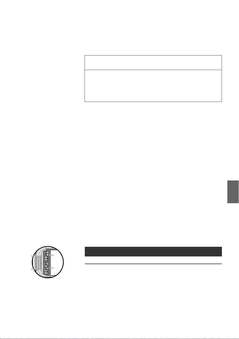
Übertragungsrate (DDL-Modus) einstellen
Die Übertragungsrate des DDL wird mit dem 5-poligen Dip-Schalter S2
auf der Vorderseite festgelegt. Alle DDL-Teilnehmer müssen auf die
gleiche Übertragungsrate eingestellt werden.
Tabelle 6: DDL-Baudrate
Schalter Bit Open On
S2 (5 bit) 5 DDL 125 kBaud DDL 250 kBaud (default)
Die Übertragungsrate kann wie folgt eingestellt werden:
1. Öffnen Sie die Abdeckung des Dip-Schalters S2.
2. Bringen Sie den Dip-Schalter S2.5 in die gewünschte Position
(siehe auch Abb. 3 „Dip-Schalter S2“).
3. Schließen Sie die Abdeckung des Dip-Schalters S2.
Buskoppler konfigurieren
Siehe „DDL-Teilnehmer – Parameter“ auf Seite 24.
Page 18

18 AVENTICS | PROFINET | R412013605–BAL–001–AC
2
1
434
3
4
3
5
2
1
5
2
1
5
BUS IN
X7E1
BUS O UT
X7E2
Inbetriebnahme
6.2 PROFINET-Schnittstelle starten
Der Anschluss an das Bussystem wird über die Datenstecker M12, 5polig, D-codiert ausgeführt. Die physikalische Reihenfolge der Geräte in
einem PROFINET-System kann beliebig gewählt werden. Die
Anschlüsse X7E1, PROFINET (2) und X7E2, PROFINET (1), siehe
Abbildung auf Seite 15, sind daher vertauschbar und können nur
außerhalb des Betriebs konfiguriert werden.
Tabelle 7: Pinbelegung, Datenstecker M12, D-codiert
Kontakt Pinbelegung
Pin 1 TD +
Pin 2 RD +
Pin 3 TD Pin 4 RD Pin 5 nicht belegt
6.3 VS mit Buskoppler in Betrieb nehmen
Bevor Sie das System in Betrieb nehmen, müssen Sie folgende Arbeiten
durchgeführt und abgeschlossen haben:
W Sie haben das Ventilsystem und den Buskoppler montiert.
W Sie haben den Buskoppler angeschlossen (siehe „Elektrisch
anschließen“ auf Seite 14).
W Sie haben die Voreinstellungen und die Konfiguration durchgeführt
(siehe „Voreinstellungen vornehmen“ auf Seite 17).
W Sie haben den Busmaster so konfiguriert, dass die Ventile richtig
angesteuert werden.
Die Inbetriebnahme und Bedienung darf nur von einer Elektrooder Pneumatikfachkraft oder von einer unterwiesenen Person
unter der Leitung und Aufsicht einer Fachkraft erfolgen (siehe
„Qualifikation des Personals“ auf Seite 8).
Page 19

AVENTICS | PROFINET | R412013605–BAL–001–AC 19
Inbetriebnahme
VORSICHT
Unkontrollierte Bewegungen der Aktoren beim Einschalten der
Pneumatik!
Es besteht Verletzungsgefahr, wenn sich das System in einem
undefinierten Zustand befindet.
O Bringen Sie das System in einen definierten Zustand, bevor Sie
es einschalten!
O Stellen Sie sicher, dass sich keine Person innerhalb des
Gefahrenbereichs befindet, wenn Sie die Druckluftversorgung
einschalten.
O Beachten Sie auch die entsprechenden Anweisungen und
Warnhinweise der Betriebsanleitung Ihres VS.
1. Schalten Sie die Betriebsspannung ein.
2. Überprüfen Sie die LED-Anzeigen an allen Modulen.
3. Schalten Sie die Druckluftversorgung ein.
6.3.1 Hochlaufverhalten
Das Hochlaufverfahren läuft wie folgt ab:
1. Der Buskoppler startet automatisch die Kommunikation mit den
DDL-Modulen und stellt fest, welche Module vorhanden sind.
Gleichzeitig teilt der PROFINET Controller dem Buskoppler die in
der Steuerung hinterlegte Konfiguration mit.
2. Der Buskoppler überprüft die Konfiguration und gibt ggf. folgende
Fehler zurück:
– DDL Adresslücke
– kein DDL Modul angeschlossen
– weniger DDL Module angeschlossen als konfiguriert
– mehr DDL Module angeschlossen als konfiguriert
3. Wenn ein Fehler erkannt wird, wartet der Buskoppler 5 Sekunden
und startet die DDL-Kommunikation erneut. Der Anwender kann
währenddessen den Adressfehler beheben (siehe auch „ DDLAdresse einstellen“ auf Seite 17). Die DDL LED bleibt im Fehlerfall
rot. Ohne Fehler geht die LED aus (siehe auch „DDL-Teilnehmer –
Parameter“ auf Seite 24). Der Buskoppler benutzt die erste gültige
Konfiguration. Nachfolgende Änderungen werden erst nach einem
Neustart übernommen.
4. Mit diesen Informationen werden die Slots und Subslots für
PROFINET erstellt. Danach wartet der Buskoppler auf die
Parameter vom PROFINET Controller.
5. Anschließend starten der Buskoppler und PROFINET-Controller den
zyklischen Datenaustausch.
6. Im Falle eines Abbruchs auf PROFINET-Seite läuft der Buskoppler
anschließend wieder an, solange sich die Parameter nicht geändert
haben, da der DDL Stack nur einmal mit Parameterübertragung
gestartet wird. Im Falle der Änderung der Parametrierung ist der
Buskoppler also auf jeden Fall neu zu starten.
Deutsch
Page 20
20 AVENTICS | PROFINET | R412013605–BAL–001–AC
BFBFSFSF
Im Betrieb
7Im Betrieb
Beachten Sie folgende Punkte für den Betrieb:
W Ändern Sie Schalter und Konfiguration nicht im laufenden Betrieb.
Geänderte Einstellungen werden erst gültig, wenn die Geräte
erneut eingeschaltet werden.
W Beachten Sie, dass über den Schirm keine durch
Potentialunterschiede bedingten Ausgleichsströme fließen dürfen.
7.1 Diagnose
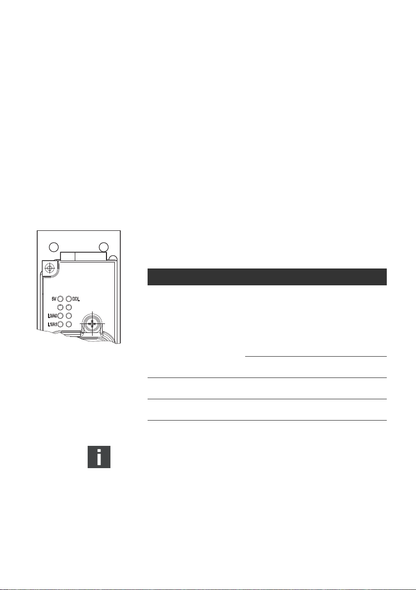
7.1.1 LED-Diagnose
Auf der Gehäuseoberseite zeigen Leuchtdioden (LED) den Zustand der
PROFINET-Schnittstelle und der Spannungsversorgung an (siehe auch
„Versorgungsspannung anschließen“).
Tabelle 8: Übersicht der PROFINET-LED-Anzeigen
Label links Label rechts Bedeutung
5 V grün DDL rot
SF rot BF rot SF: System Failure (Fehler System)
LINK0 grün LINK0/ACT0: leuchtet wenn ein Link besteht,
LINK1 grün LINK0/ACT1: leuchtet wenn ein Link besteht,
5 V: leuchtet, wenn Versorgungsspannung >18 V
DDL:
W Leuchtet bei Konfigurationsfehler
(Adresse, Baudrate,
Abschlusswiderstand)
W Leuchtet bei Initialisierung und blinkt
nach erfolgreicher Initialisierung
W Aus bei DDL-Kommunikation
BF: Bus Failure (Fehler Buskoppler)
blinkt beim Senden und Empfangen von Daten
blinkt beim Senden und Empfangen von Daten
Die Spannungsversorgung für Ventile wird am Buskoppler nicht
überwacht.
7.1.2 Software-Diagnose
Der Buskoppler stellt Diagnosedaten zur Verfügung:
Detaillierte Informationen zum Diagnoseaufbau der einzelnen DDLTeilnehmer kann der Beschreibung der jeweiligen DDL-Teilnehmer
entnommen werden (siehe auch „Software-Diagnose“ auf Seite 25).
Page 21

AVENTICS | PROFINET | R412013605–BAL–001–AC 21
Demontage und Austausch
8 Demontage und Austausch
8.1 Buskoppler demontieren
ACHTUNG
Sachschaden bei anliegender Spannung!
Unkontrolliertes Trennen von der Spannung kann das Produkt oder
Anlagenteile beschädigen.
O Schalten Sie den relevanten Anlagenteil spannungsfrei, bevor
Sie das Gerät demontieren bzw. Stecker abziehen.
1. Schalten Sie die 24-V-DC-Elektronik- und Ventilversorgung ab.
2. Entfernen Sie die angeschlossenen Stecker.
3. Lösen Sie den Buskoppler von der Arbeitsfläche.
4. Entfernen Sie den Buskoppler.
9Entsorgung
Entsorgen Sie das Produkt nach den Bestimmungen Ihres Landes.
10 Instandhaltung und Instandsetzung
10.1 Reinigung und Pflege
ACHTUNG
Beschädigung der Oberfläche durch Lösemittel und aggressive
Reinigungsmittel!
Die Oberflächen und Dichtungen können durch Lösemittel oder
aggressive Reinigungsmittel beschädigt werden.
O Verwenden Sie niemals Lösemittel oder aggressive
Reinigungsmittel.
O Reinigen Sie das Gerät ausschließlich mit einem leicht feuchten
Tuch. Verwenden Sie dazu nur Wasser und ggf. ein mildes
Reinigungsmittel.
O Überprüfen Sie, ob alle Dichtungen und Verschlüsse der
Steckverbindungen fest sitzen, damit bei der Reinigung keine
Feuchtigkeit in den Buskoppler eindringen kann.
Deutsch
Page 22

22 AVENTICS | PROFINET | R412013605–BAL–001–AC
Fehlersuche und Fehlerbehebung
10.2 Wartung
Der Buskoppler ist wartungsfrei. Unter aggressiven
Umgebungsbedingungen können jedoch die Dichtungen des
Buskopplers schneller altern. Defekte Dichtungen führen zu
pneumatischen Leckagen und zum Verlust der Schutzklasse IP65.
O Überprüfen Sie regelmäßig, ob die Dichtungen am Buskoppler
einwandfrei sind. Legen Sie die Wartungsintervalle je nach Ihren
Umgebungsbedingungen fest und tragen Sie diese in den
anlagenspezifischen Wartungsplan ein.
O Beachten Sie die anlagenspezifischen Wartungsintervalle.
11 Fehlersuche und Fehlerbehebung
Störung mögliche Ursache Abhilfe
LED 5V leuchtet nicht Keine Spannung vorhanden Spannungsversorgung am Buskoppler
Buskoppler defekt Buskoppler austauschen.
Falsch konfektioniertes oder defektes
Kabel
LED L1/A1 bzw. L2/A2 leuchtet
nicht
LED DDL leuchtet dauerhaft Fehlerhafte DDL Konfiguration Kontrolle der Baudrate, lückenlose
LED SF leuchtet Diagnose ist eingeschaltet und es liegt
LED BF leuchtet Konfiguration stimmt nicht mit der
Es besteht keine physische Verbindung
zwischen PROFINET Controller und
Buskoppler.
eine Diagnose an.
angeschlossenen Hardware überein.
prüfen.
Geprüfte Kabel verwenden.
Ethernetkabel und PROFINET-Anschlüsse
überprüfen.
Adressierung 1 - x, Abschlusswiderstand
vorhanden.
Diagnose an den Teilnehmern
kontrollieren.
Konfiguration der Hardware angleichen.
Falls andere Fehler auftreten, wenden Sie sich bitte an eine der
Kontaktadressen, die Sie unter www.aventics.com/contact finden.
Page 23

AVENTICS | PROFINET | R412013605–BAL–001–AC 23
Technische Daten
12 Technische Daten
Allgemeine Daten
Abmessungen (Breite x Höhe x Tiefe) 50 mm x 120,5 mm x 106,5 mm
Gewicht ca. 425 g
Lagerbedingung < 80 % RH
relative Luftfeuchtigkeit 0 – 95 %
Schutzart nach EN 60529/IEC 529 IP65 (nur in montiertem Zustand und mit allen montierten Steckern/mit
Versorgungsspannung Sensorspannung 24 V DC (20 %)
Zulässige Oberwelligkeit 5 %
Einbaulage beliebig
Absicherung der Spannung Ventile
extern
Absicherung der Spannung
Elektronik extern
Achtung: Maximaler Strom in der 0-VLeitung
Spannungsabfall intern 0,8 V
Strombedarf Elektronik 90 mA
Stromversorgung für Initiatoren max. 3 A pro DDL-Strang
Stromversorgung für Ventile max. 3 A pro DDL-Strang
Hochlaufzeit nach Einschalten der
Versorgungsspannung
Thermischer Anwendungsbereich +5 °C bis +50 °C
Lagertemperatur -20 °C bis +70 °C
Berücksichtigte Normen und
Richtlinien
verschlossenen Leitungsdosen)
Ventilspannung 24 V DC (10 %)
Die Versorgungsspannung muss aus einem Netzteil mit sicherer Trennung
erfolgen.
3A T
3A T
max. 4 A
2s
2004/108/EG „Elektromagnetische Verträglichkeit“ (EMV-Richtlinie)
DIN EN 61000-6-2 „Elektromagnetische Verträglichkeit“ (Störfestigkeit
Industriebereich)
DIN EN 61000-6-4 „Elektromagnetische Verträglichkeit“ (Störaussendung
Industriebereich)
DIN EN 60204-1 „Sicherheit von Maschinen - Elektrische Ausrüstung von
Maschinen - Teil 1: Allgemeine Anforderungen“
Deutsch
Page 24

24 AVENTICS | PROFINET | R412013605–BAL–001–AC
Anhang
13 Anhang
13.1 PROFINET-Konfiguration
Für die SPS-Konfigurations-Software, z. B. S7 Simatic Manager, sind
ggf. die GSDML-Dateien für den Buskoppler sowie jedes verwendete
DDL-Modul notwendig.
Diese Datei kann unter www.aventics.com/mediadirectory
heruntergeladen werden.
Das Datenmodell für den PROFINET DDL Buskoppler ist durch
verschiedene Module beschrieben. Jedes Modul (Nr. 1 bis max. 14)
repräsentiert ein DDL-Modul und enthält je ein Submodul für Input
(Nr. 1), Output (Nr. 2) und Diagnose (Nr. 3). Diagnose-Alarme und
Parameter sind dabei jeweils dem Diagnose-Submodul zugeordnet.
Zusätzlich enthält Modul 0 die PROFINET-spezifischen Submodule für
DAP, Device und beide Ports. Submodul 1 (Device) enthält 4 Byte
Buskoppler-Diagnosedaten (Lifesign, Fehlerbits und
Anwesenheitsliste).
Da es mit einigen PROFINET-CPUs Kompatibilitätsprobleme gibt, lassen
sich die 4 Byte Buskoppler-Diagnosedaten auch über einen 15.
Teilnehmer (DDL Master Diagnosis) abrufen. Dieser Teilnehmer lässt
sich nur in Slot 15 positionieren.
Vor der eigentlichen Inbetriebnahme muss dem Buskoppler über
Ethernet (DCP) ein Gerätename zugewiesen werden, damit der
PROFINET-Controller eine Verbindung öffnen kann. Dieser
Gerätename wird im Flash-Speicher gespeichert. Im
Auslieferungszustand ist dieser Gerätename leer, wie es vom
PROFINET-Standard vorgesehen ist.
Damit der Name vergeben werden kann, muss am Buskoppler eine
korrekte DDL-Konfiguration angeschlossen sein, so dass die DDLLED blinkt.
13.2 DDL-Teilnehmer – Parameter
Die Parameterbeschreibungen der einzelnen DDL-Teilnehmer sind den
entsprechenden Betriebsanleitung zu entnehmen.
13.3 PROFINET Diagnose Alarme
Der Buskoppler ermöglicht es, Störungen an den PROFINET Controller
zu melden. Es wird „Extended Channel Diagnosis“ benutzt.
Page 25

AVENTICS | PROFINET | R412013605–BAL–001–AC 25
Anhang
Alarme vom Buskoppler werden auf Slot0, Subslot1 ausgegeben. Diese
können sein:
W DDL Adresslücke
W kein DDL Modul angeschlossen
W weniger DDL Module angeschlossen als konfiguriert
W mehr DDL Module angeschlossen als konfiguriert
Außer bei der Meldung „keine DDL Module“ wird jeweils die
Anwesenheitsliste als zusätzlicher Parameter mit übertragen.
Zusätzlich wird das StdDiag-Byte von jedem angeschlossenen DDLModul überwacht und ggf. die Meldung:
W DDL Modul- StdDiag mit dem StdDiag-Byte als Parameter
übertragen. Alle diese Fehlermeldungen können gleichzeitig
anliegen und werden jeweils gelöscht, wenn der Fehler behoben ist.
13.4 Datenleitung DDL
Der Ausgang des DDL ist auf allen Leitungen kurzschlussfest. Jedoch
können DDL-Teilnehmer beschädigt werden, wenn 24 V an den
Signalleitungen DDL H und DDL L anliegen.
Aus diesem Grund wird empfohlen, vorkonfektionierte Kabel zu
verwenden. Die Belegung der DDL-Anschlüsse ist in der DDLSystembeschreibung (R499050030) beschrieben.
Der DDL-Abschlussstecker wird benötigt, falls das Modul der letzte bzw.
einzige Teilnehmer eines DDL-Strangs ist. Damit ist ein definierter
Leitungsabschluss gewährleistet und das Modul erfüllt die Schutzart IP65.
13.5 Software-Diagnose
Deutsch
Der Buskoppler stellt Diagnosedaten zur Verfügung:
Detaillierte Informationen zum Diagnoseaufbau der einzelnen DDLTeilnehmer kann der Beschreibung der jeweiligen DDL-Teilnehmer
entnommen werden.
Das Weiterleiten der Diagnose an die SPS kann mit dem Dip-Schalter
S1.1 unterbunden werden.
S1.1 auf 0 Die Diagnosedaten werden nicht an die SPS gesendet (default).
S1.1 auf 1 Die Diagnosedaten werden an die SPS gesendet.
Warnungen werden selbstständig gelöscht, sobald die Ursache
behoben ist. Es kann immer nur eine Meldung dargestellt werden.
Bei Änderungen am DDL wird empfohlen, immer einen
Spannungsreset durchzuführen.
Page 26

26 AVENTICS | PROFINET | R412013605–BAL–001–AC
Anhang
13.6 PROFINET – Unterstützte Funktionen
Tabelle 9: Unterstützte und eingeschränkte PROFINET-Funktionen
Unterstützte Protokolle RTC – Real time Cyclic Protocol, Class 1
Maximale Datenmenge der zyklischen Eingangsdaten 16 bytes
Maximale Datenmenge der zyklischen Ausgangsdaten 16 bytes
Maximale Zeichenanzahl der Slot-Adresse 255
Maximale Zeichenanzahl der Subslot-Adresse 10
Alarmtypen Process Alarm, Diagnostic Alarm, Return of SubModule, Plug
Verwendete Protokolle (Teilmenge) UDP, IP, ARP, ICMP (Ping)
Topologie-Erkennung LLDP, SNMP V1, MIB2, Physical Device
VLAN- und Datenpriorisierung
Minimale Zykluszeit 1 ms
Konformität Class A
Baudrate 100 Mbit/s
Netzwerkprotokoll Ethernet II, IEEE 802.3
Nicht unterstützt RT over UDP
RTA – Real time Acyclic Protocol
DCP – Discovery and Configuration Protocol
CL-RPC – Connectionless Remote Procedure Call
LLDP – Link Layer Discovery Protocol
SNMP – Simple Network Management Protocol
Alarm, Pull Alarm
IRT “flex” (synchronized RT Class 2)
Fast Start Up
Media redundancy
Supervisor AR
Shared Device not supported
Multicast communication
DHCP
Page 27

AVENTICS | PROFINET | R412013605–BAL–001–AC 27
14 Stichwortverzeichnis
Stichwortverzeichnis
W A
Abkürzungen
Abmessungen 14
Anschließen
Versorgungsspannung
W D
Datenleitung DDL
DDL-Adresse 17
DDL-Baudrate 17
DDL-Modus 17
DDL-Teilnehmer –
Parameter
Dokumentation,
zusätzliche
W E
Elektrisch anschließen
W H
Hochlaufverhalten
W L
LED-Diagnose
Leistungsbeschreibung 11
7
24
5
20
25
19
14
15
W Q
Qualifikation des Personals
W V
Versorgungsspannung
Ventilspule
Verwendung
bestimmungsgemäß
nicht
bestimmungsgemäß
Voreinstellungen 17
15
8
8
8
Deutsch
W M
Montage
Versorgungsspannung
anschließen
W P
PROFINET Diagnose
Alarme
PROFINET Unterstützte
Funktionen
PROFINET-Konfiguration 24
PROFINET-Schnittstelle 18
15
24
26
Page 28

28 AVENTICS | PROFINET | R412013605–BAL–001–AC
Stichwortverzeichnis
Page 29

AVENTICS | PROFINET | R412013605–BAL–001–AC 29
Contents
Contents
1 About This Documentation ..................................................... 31
1.1 Documentation validity....................................................................... 31
1.2 Required and supplementary documentation ............................ 31
1.3 Presentation of information.............................................................. 31
1.3.1 Safety instructions ............................................................................. 31
1.3.2 Symbols ................................................................................................ 32
1.3.3 Abbreviations used ............................................................................ 32
2 For your safety ........................................................................ 33
2.1 About this chapter................................................................................ 33
2.2 Intended use .......................................................................................... 33
2.3 Improper use ......................................................................................... 33
2.4 Personnel qualifications.....................................................................34
2.5 General safety instructions ...............................................................34
2.6 Safety instructions related to the product and technology..... 35
3 Delivery Contents .................................................................... 35
4 About this Product ................................................................... 36
4.1 Performance specifications ..............................................................36
4.2 Product description ............................................................................. 36
4.3 Product identification.......................................................................... 37
5 Assembly .................................................................................. 37
5.1 Assembling the product..................................................................... 37
5.1.1 Dimensions .......................................................................................... 38
5.2 Electrical connection........................................................................... 39
5.2.1 Connecting the DDL and bus coupler ........................................... 39
5.2.2 Connecting the supply voltage ....................................................... 39
6 Commissioning ........................................................................ 41
6.1 Commissioning for the first time.....................................................41
6.1.1 Making presettings ............................................................................ 41
6.2 Starting the PROFINET interface..................................................... 42
6.3 Commissioning the VS with bus coupler ...................................... 42
6.3.1 Start-up procedure ............................................................................ 43
7 During operation ..................................................................... 44
7.1 Diagnosis ................................................................................................ 44
7.1.1 LED diagnosis ...................................................................................... 44
7.1.2 Software diagnosis ............................................................................ 44
8 Disassembly and Exchange ................................................... 45
8.1 Disassembling the bus coupler ....................................................... 45
9 Disposal .................................................................................... 45
10 Service and Repairs ................................................................ 45
10.1 Cleaning and servicing ....................................................................... 45
10.2 Maintenance........................................................................................... 46
11 Troubleshooting ...................................................................... 46
English
Page 30

30 AVENTICS | PROFINET | R412013605–BAL–001–AC
Contents
12 Technical Data ......................................................................... 47
13 Appendix .................................................................................. 48
13.1 PROFINET configuration..................................................................... 48
13.2 DDL participant parameters ............................................................. 48
13.3 PROFINET diagnosis alarms............................................................. 48
13.4 DDL data line .........................................................................................49
13.5 Software diagnosis..............................................................................49
13.6 PROFINET supported functions........................................................50
14 Index ......................................................................................... 51
Page 31

AVENTICS | PROFINET | R412013605–BAL–001–AC 31
About This Documentation
1 About This Documentation
1.1 Documentation validity
This documentation contains important information on the safe and
appropriate assembly, operation, and maintenance of the bus coupler
and how to remedy simple malfunctions yourself.
O Read this documentation completely, especially chapter “For your
safety”, before working with the bus coupler.
1.2 Required and supplementary documentation
O Only commission the product once you have obtained the following
documentation and understood and complied with its contents.
Table 1: Required and supplementary documentation
Titl e Document number Document type
DDL system description R499050030 Instructions
System documentation
Further information on the components can be found in the online
catalog at www.aventics.com/pneumatics-catalog.
1.3 Presentation of information
To allow you to begin working with the product quickly and safely,
uniform safety instructions, symbols, terms, and abbreviations are used
in this documentation. For better understanding, these are explained in
the following sections.
1.3.1 Safety instructions
This documentation contains safety instructions before any steps that
involve a risk of personal injury or damage to property. The measures
described to avoid these hazards must be observed.
Safety instructions are set out as follows:
English
Page 32

32 AVENTICS | PROFINET | R412013605–BAL–001–AC
About This Documentation
Hazard type and source
Consequences
O Precautions
W Safety sign: draws attention to the risk
W Signal word: identifies the degree of hazard
W Hazard type and source: identifies the hazard type and source
W Consequences: describes what occurs when the safety instructions
are not complied with
W Precautions: states how the hazard can be avoided
Table 2: Hazard classes according to ANSI Z535.6-2006
Safety sign, signal word Meaning
CAUTION
NOTICE
1.3.2 Symbols
SIGNAL WORD
Indicates a hazardous situation which,
if not avoided, could result in minor or
moderate injuries.
Indicates damage: the product or the
environment may be damaged.
The following symbols indicate information that is not relevant for
safety but that assists in comprehending the documentation.
Table 3: Meaning of the symbols
Symbol Meaning
If this information is disregarded, the product cannot be used or
operated optimally.
O
1.
2.
3.
Individual, independent action
Numbered steps:
The numbers indicate sequential steps.
1.3.3 Abbreviations used
This documentation uses the following abbreviations:
Table 4: Abbreviations
Abbreviation Meaning
VS Valve system
DDL Drive & Diagnostic Link
FE Functional Earth
Page 33

AVENTICS | PROFINET | R412013605–BAL–001–AC 33
For your safety
2For your safety
2.1 About this chapter
The product has been manufactured according to the accepted rules of
safety and current technology. There is, however, still a danger of
personal injury or damage to equipment if the following general safety
instructions and the warnings before the steps contained in these
instructions are not complied with.
O
Read these instructions completely before working with the product.
O Keep these instructions in a location where they are accessible to
all users at all times.
O Always include the operating instructions when you pass the bus
coupler on to third parties.
2.2 Intended use
The product is an electropneumatic system component.
The product may be used as follows:
O only for industrial applications.
O only within the performance range provided in the technical data
The product is intended for professional use only.
Intended use includes having read and understood this documentation,
especially the chapter “For your safety”, and the DDL system description
R499050030.
2.3 Improper use
Any use other than that described under Intended use is improper and
is not permitted.
The installation or use of unsuitable products in safety-relevant
applications can result in unanticipated operating states in the
application that can lead to personal injury or damage to equipment.
Therefore, only use a product in safety-relevant applications if such use
is specifically stated and permitted in the product documentation. For
example, in areas with explosion protection or in safety-related
components of control systems (functional safety).
AVENTICS GmbH is not liable for any damages resulting from improper
use. The user alone bears the risks of improper use of the product.
Improper use of the bus coupler includes:
W use for any application not described in these instructions.
W use under operating conditions not described in these instructions
or in the DDL system description (R499050030).
English
Page 34

34 AVENTICS | PROFINET | R412013605–BAL–001–AC
For your safety
2.4 Personnel qualifications
Assembly, disassembly, commissioning, and operation require basic
electrical and pneumatic knowledge, as well as knowledge of the
appropriate technical terms. Assembly, disassembly, commissioning,
and operation may therefore only be carried out by qualified electrical
or pneumatic personnel or an instructed person under the direction and
supervision of qualified personnel.
Qualified personnel are those who can recognize possible hazards and
institute the appropriate safety measures due to their professional
training, knowledge, and experience, as well as their understanding of
the relevant conditions pertaining to the work to be done. Qualified
personnel must observe the rules relevant to the subject area.
2.5 General safety instructions
General instructions W Observe the regulations for accident prevention and environmental
Transport and storage W A problem-free and safe operation of the devices requires proper
protection.
W Observe the safety instructions and regulations of the country in
which the product is used or operated.
W Only use AVENTICS products that are in perfect working order.
W Follow all the instructions on the product.
W Persons who assemble, operate, disassemble, or maintain
AVENTICS products must not consume any alcohol, drugs, or
pharmaceuticals that may affect their ability to respond.
W To avoid injuries due to unsuitable spare parts, only use accessories
and spare parts approved by the manufacturer.
W Comply with the technical data and ambient conditions listed in the
product documentation.
W If unsuitable products are installed or used in safetyrelevant
applications, this may result in unintended system operating states
that may lead to injuries and/or equipment damage. Therefore, only
use a product in safety-relevant applications if such use is
specifically stated and permitted in the product documentation.
W
You may only commission the product if you have determined that the
end product (such as a machine or system) in which the AVENTICS
products are installed meets the country-specific provisions, safety
regulations, and standards for the specific application.
W Do not change or modify the device.
W Only use the device within the performance range provided in the
technical data.
W Do not place any mechanical loads on the device under any
circumstances. Do not place any loose objects on it.
W The warranty only applies when the product is used as intended.
W Observe related safety notes in the operating instructions.
transport, correct storage, installation and assembly.
Page 35

AVENTICS | PROFINET | R412013605–BAL–001–AC 35
Delivery Contents
During cleaning W Only clean the device using a slightly damp cloth. Only use water
and, if necessary, a mild detergent.
2.6 Safety instructions related to the product and technology
Before assembly W The bus coupler (electrostatically endangered components) may
On installation W Always assemble the bus coupler on a mounting plate or in a
only be opened by trained personnel.
W Make sure the relevant system component is not under pressure or
voltage before assembling or when connecting and disconnecting
plugs. Protect the system against being switched on.
W Only use a power pack with safe isolation in accordance with
DIN EN 60742, classification VDE 0551 for the power supply. Please
pay attention to external fuses that comply with this description.
W The warranty will not apply if the product is incorrectly assembled.
control cabinet.
W Observe the installation position described in the operating
instructions.
W Lay the cables so that no one can trip over them.
W Other system parts may be damaged by uncontrolled device
movements if it has not been properly mounted. Make sure that the
device is securely fastened.
W Ground the devices according to national regulations.
W Only use cables indicated in the operating instructions or quotation
drawings.
Commissioning W Installation/assembly and commissioning of the device may only be
carried out in a voltage-free and pressure-free state by trained and
qualified specialists.
W Only put the device into operation if it has been completely
assembled, correctly wired and tested.
W Before connecting or disconnecting the plugs, switch off the
operating voltage to prevent damage to the electrical system.
During operation W Observe related safety notes in the operating instructions.
3 Delivery Contents
The following is included in the delivery contents:
W 1 bus coupler PROFINET DDL (R412013399)
W 1 assembly and maintenance instructions (R412013605)
English
Page 36

36 AVENTICS | PROFINET | R412013605–BAL–001–AC
X7E1
X7E2
XPD
X1S
SF
BF
DDL PROFINET
1
6
2
3
4
1
5
About this Product
4 About this Product
4.1 Performance specifications
The bus coupler is used to connect the DDL system to a PROFINET field bus.
The bus coupler communicates with the field bus system and monitors
the DDL (Drive and Diagnostic Link).
The bus coupler is designed only for use as a device on a PROFINET bus
system.
The bus coupler is a modular I/O device that conforms to PROFINET
specifications.
The bus coupler connects the local I/O devices with the PROFINET
network. In the data model, these I/O devices are modularly connected
to the bus coupler.
The bus coupler functions as an interface between the PROFINET
network and the local DDL participants.
4.2 Product description
Fig. 1: Bus coupler
1 PROFINET LEDs
2 X7E2: PROFINET IN
3 X7E1: PROFINET OUT
4 XPD: DDL connection
5 X1S: M12 power supply
(integrated X1S power supply plug)
6 S1/S2
Page 37

AVENTICS | PROFINET | R412013605–BAL–001–AC 37
Assembly
4.3 Product identification
Comply with the product information on the product and the packaging.
5 Assembly
CAUTION
Danger of injury if assembled under pressure or voltage!
Assembling when under pressure or electrical voltage can lead to
injuries and damage to the product or system components.
O Make sure that the relevant system part is not under voltage or
pressure before you assemble the product.
O Protect the system against being switched on.
5.1 Assembling the product
CAUTION
Danger of injury if assembled incorrectly!
Incorrect assembly can lead to uncontrolled product or system
movements.
O Make sure that the bus coupler is correctly fastened.
O Make sure that the device is securely fastened with the correct
tightening torque.
1. Let the bus coupler acclimate itself for several hours before
installation; otherwise water may condense in the housing.
2. Make sure the relevant system part is not under voltage or
pressure.
3. Remove the four mounting screws.
4. Set the bus coupler in the desired position on the mounting plate
(any) or control cabinet (on the side).
5. Tighten the four M5 mounting screws (tightening torque: 6 Nm).
English
Page 38

38 AVENTICS | PROFINET | R412013605–BAL–001–AC
10
21,4
30
34,5
1515
5,5
6060
3,5
120
40,6
60,3
79,8
84,5
106,5
1) 2) 3) 4)
49,5
140
120,5
13
45
50
BFBFSFSF
DDL PROFINETDDL PROFINET
Assembly
5.1.1 Dimensions
Fig. 2: Bus coupler, dimensions
Page 39

AVENTICS | PROFINET | R412013605–BAL–001–AC 39
1
X7E1
X7E2
XPD
X1S
2
3
4
2
1
43
PO WE R
X1S
Assembly
5.2 Electrical connection
5.2.1 Connecting the DDL and bus coupler
The electrical connections of the bus coupler are established using
threaded M12x1 round plug connectors.
O Attach the connectors to the bus coupler.
NOTICE
Material damage due to penetration of liquids and foreign objects!
Liquids and foreign objects could penetrate the plug connections if
seals and plugs are missing and cause damage to the product or
system components.
O Use round plug connectors with the IP 65 protection class
or better.
O Make sure that the seals are integrated in the plug
and not damaged.
O Close all unused plug connectors with protective caps/blanking
plugs.
O Make sure that all plugs are correctly connected
before commissioning.
A functional ground is connected via the X1S connection (see Tab. 5).
5.2.2 Connecting the supply voltage
The valve solenoids are provided with power via the integrated
X1S POWER SUPPLY (4) plug.
Table 5: X1S pin assignment
Contact Pin assignment
1)
Pin 1
2)
Pin 2
Pin3 0V (max. 4A)
Pin 4 Functional ground
1)
The electronics of the bus coupler and the electronics of all I/O modules and initiators
connected through the DDL are supplied via X1S, Pin 1 (for modules without external
voltage supply).
2)
When using modules without an external voltage supply, the switching voltage for the
connected valves must be supplied via X1S, Pin 2.
24 V electronics
24 V valves
English
Page 40

40 AVENTICS | PROFINET | R412013605–BAL–001–AC
Assembly
The separate supply voltages via Pin 1 and Pin 2 make it possible
to switch off only the valves in an emergency OFF situation, while
the PLC, serial interfaces and initiators remain in operation.
Shutting off the power supply for the serial interface can cause the
PLC to STOP.
Damage can occur if the device is assembled or disassembled
under voltage/load!
Inadvertently connecting and disconnecting the product or system
parts under voltage/load can cause damage.
O Make sure that all relevant system parts are not under voltage
before inserting or disconnecting plug connectors.
W Only use 4-pin M12 connection sockets where pin 5 is closed, in
order to rule out confusion with other connections.
W Make sure that the largest connection cross-section possible is
selected, at least 0.55 mm².
W Secure both supply voltages with external 3-A-T fuses.
– The applied supply voltage is indicated by a green LED (5 V):
The LED illuminates as soon as the electronics voltage > 18 V
(see also table 8 “Overview of PROFINET LED displays”).
– The maximum permissible current in the 0 V line is limited to 4 A
by the plug connector.
– Only use a shared power pack or a shared 0 V connection for the 24 V
power supply. The power pack must be one with safe isolation in
accordance with DIN EN 60742, classification VDE 0551.
NOTICE
Page 41

AVENTICS | PROFINET | R412013605–BAL–001–AC 41
Commissioning
6 Commissioning
The bus coupler may only be commissioned with the entire system in
which it is installed.
O Contact the system manufacturer if you want to commission the
bus coupler.
6.1 Commissioning for the first time
NOTICE
Damage due to uncontrolled device movements!
The bus coupler and other system parts may be damaged by
uncontrolled device movements.
O Commissioning of the bus coupler may only be carried out in a
pressure-free state.
6.1.1 Making presettings
The following prerequisites must be fulfilled:
W The transfer rate must be set the same for all DDL modules.
W The addressing conditions of the DDL (Drive & Diagnostic Link) must
be fulfilled.
W The DDL configuration must be set and tested.
W The terminating resistor after the last DDL participant must be
connected.
Setting the DDL address
No DDL address has to be set on the bus coupler
For the DDL (Drive & Diagnostic Link) to function properly, the following
addressing conditions must be fulfilled:
W DDL address from 1-14, starting at 1, without gaps, no address
assigned twice
DDL address 0: see DDL system description (R499050030).
Setting the transfer rate (DDL mode)
The DDL transfer rate is determined with the 5-pin S2 DIP switch on the
front side. All DDL participants must be set to the same transfer rate.
English
Page 42

42 AVENTICS | PROFINET | R412013605–BAL–001–AC
Fig. 3: S2 DIP switch
2
1
434
3
4
3
5
2
1
5
2
1
5
BUS IN
X7E1
BUS O UT
X7E2
Commissioning
Table 6: DDL baud rate
ON ONAPEMs APEMs
1
S2.1-S2.5S1.1-S1.4
234 12345
S1
S2
Switch Bit Open On
S2 (5 bits) 5 DDL 125 k-baud DDL 250 k-baud (default)
The transfer rate can be set as follows:
1. Open the cover of the S2 DIP switch.
2. Move the S2.5 DIP switch to the desired position
(see also Fig. 3: S2 DIP switch).
3. Close the cover of the S2 DIP switch.
Configuring the bus coupler
See “DDL participant parameters” on page 48.
6.2 Starting the PROFINET interface
The bus system is connected using M12, 5-pin, D-coded data plugs. The
physical sequence of the devices in a PROFILNET system can be chosen
arbitrarily. The X7E1, PROFINET (2) and X7E2, PROFINET (1)
connections (see figure on page 39) are therefore interchangeable and
may only be configured when not in operation.
Table 7: Pin assignment, M12 data plug, D-coded
Contact Pin assignment
Pin 1 TD +
Pin 2 RD +
Pin 3 TD Pin 4 RD Pin 5 Not connected
6.3 Commissioning the VS with bus coupler
Before commissioning the system, the following steps must have been
carried out and completed:
W You have assembled the valve system and the bus coupler.
W You have connected the bus coupler
(see “Electrical connection” on page 39).
W You have made the settings and configured the system
(see “Making presettings” on page 41).
W You have configured the bus master so that it actuates the valves
correctly.
Commissioning may only be carried out by qualified electrical or
pneumatic personnel or an instructed person under the direction
and supervision of qualified personnel (see “Personnel
qualifications” on page 34).
Page 43

AVENTICS | PROFINET | R412013605–BAL–001–AC 43
Commissioning
CAUTION
Risk of uncontrolled actuator movements when the pneumatics are
switched on!
There is a danger of personnel injury if the system is in an undefined
state.
O Put the system in a defined state before switching it on.
O Make sure that no personnel are within the hazardous zone
when the compressed air supply is switched on.
O Also observe the applicable instructions and safety information
in the VS operating instructions.
1. Switch on the operating voltage.
2. Check the LED displays on all modules.
3. Switch on the compressed air supply.
6.3.1 Start-up procedure
The start-up procedure is as follows:
1. The bus coupler automatically starts the communication with the
DDL modules and determines which modules are present. At the
same time, the PROFINET controller informs the bus coupler of the
configuration saved in the controller.
2. The bus coupler checks the configuration and returns the following
error messages where necessary:
– DDL bus address gap
– No DDL modules connected
– Fewer DDL modules connected than configured
– More DDL modules connected than configured
3. If an error is recognized, the bus coupler waits 5 seconds and
restarts the DDL communication.
The user can then resolve the address error (see also “ Setting the
DDL address” on page 41). The DDL LED stays red in the event of an
error. If the error has been resolved, the LED extinguishes (see also
“DDL participant parameters” on page 48). The bus coupler uses the
first valid configuration. Any subsequent changes only take effect
once the system has been restarted.
4. This information is used to created slots and subslots for PROFINET.
The bus coupler then waits for the parameters from the PROFINET
controller.
5. The bus coupler and PROFINET controller then both start the
cyclical exchange of data.
6. In the event of an abort by PROFINET, the bus coupler then starts up
again as long as the parameters remain unchanged, as the DDL
stack is only started once with the transfer of parameters. In the
event of changes to the parameters, the bus coupler must be
restarted.
English
Page 44

44 AVENTICS | PROFINET | R412013605–BAL–001–AC
BFBFSFSF
During operation
7 During operation
Observe the following points for operation:
W Do not change the switch and configuration during operation.
Changed settings only take effect after the devices have been
switched on again.
W Please note that compensating currents caused by differences in
potential must not flow via the shielding.
7.1 Diagnosis
7.1.1 LED diagnosis
On top of the housing, light emitting diodes (LEDs) indicate the status of
the PROFINET interface and the power supply (see also “Connecting the
supply voltage”).
Table 8: Overview of PROFINET LED displays
Label left Label right Meaning
5V green DDL red
SF red BF red SF: System Failure
LINK0 green
LINK1green
5 V: illuminates if supply voltage is > 18 V
DDL:
W Illuminates for configuration errors
(address, baud rate, terminating resistor)
W Illuminates during initialization and
flashes after successful initialization
W OFF during DDL communication
BF: Bus Failure (bus coupler error)
LINK0/ACT0: illuminated if a link exists, flashes,
flashes when sending and receiving data
LINK0/ACT1: illuminated if a link exists, flashes,
flashes when sending and receiving data
The power supply for valves is not monitored at the bus coupler.
7.1.2 Software diagnosis
The bus coupler provides diagnostic data:
Detailed information on the diagnosis structure of the individual DDL
participants can be found in the descriptions of the respective DDL
participants (see also “Software diagnosis” on page 49).
Page 45

AVENTICS | PROFINET | R412013605–BAL–001–AC 45
Disassembly and Exchange
8 Disassembly and Exchange
8.1 Disassembling the bus coupler
NOTICE
Damage can occur if the device is under voltage!
Inadvertently disconnecting the voltage can damage the product or
system parts.
O Make sure the relevant system component is not under voltage
before disassembling the device or when disconnecting plugs.
1. Switch off the 24 V DC electronics power supply and valve supply.
2. Remove the connected plugs.
3. Loosen the bus coupler from the work surface.
4. Remove the bus coupler.
9Disposal
Dispose of the product in accordance with the currently applicable
regulations in your country.
10 Service and Repairs
10.1 Cleaning and servicing
NOTICE
Damage to the surface caused by solvents and aggressive
detergents!
The surfaces and seals could be damaged by solvents or aggressive
cleaning agents.
O Never use solvents or strong detergents.
O Only clean the device using a slightly damp cloth. Only use water
to do this and, if necessary, a mild detergent.
O Check that all seals and plugs for the plug connections are firmly
fitted so that no humidity can penetrate the bus coupler during
cleaning.
English
Page 46

46 AVENTICS | PROFINET | R412013605–BAL–001–AC
Troubleshooting
10.2 Maintenance
The bus coupler is maintenance-free. However, the seals of the bus
coupler may age faster under aggressive ambient conditions. Defective
seals will lead to pneumatics leaks and non-compliance with the IP 65
protection class.
O Regularly check that the seals on the bus coupler are in perfect
order. Establish the maintenance intervals according to your
ambient conditions and enter them in the system-dependent
maintenance plan.
O Observe the system-specific maintenance intervals.
11 Troubleshooting
Malfunctioning Possible cause Remedy
LED 5 V not illuminated No voltage available Check the power supply to the bus coupler
Defective bus coupler Exchange the bus coupler
Incorrectly assembled or defective cable Use tested cables.
LED L1/A1 or L2/A2 not
illuminated
LED DDL is permanently
illuminated
SF LED illuminated Diagnosis is switched on and there is a
BF LED illuminated Configuration does not match the
There is no physical connection between
the PROFINET Controller and bus coupler.
Faulty DDL configuration
diagnosis.
connected hardware.
Check the Ethernet cable and PROFINET
connections.
Check the baud rate, consecutive addressing
1-x, terminating resistor present.
Check diagnosis on the participants.
Adjust hardware configuration.
If any other errors occur, please contact one of the addresses found
under www.aventics.com/contact.
Page 47

AVENTICS | PROFINET | R412013605–BAL–001–AC 47
12 Technical Data
General data
Dimensions (width x height x depth) 50 mm x 120.5 mm x 106.5 mm
Weight Approx. 425 g
Storage conditions < 80 % RH
Relative humidity 0 – 95 %
Protection class according to
EN 60529/IEC529
Supply voltage 24 V DC sensor voltage (±20 %)
Permissible ripple 5 %
Mounting orientation Any
Fuse for voltage: external valves 3 A T
Fuse for voltage: external electronics 3 A T
Warning: maximum current in the 0 V
line
Internal voltage drop 0.8 V
Current requirement for electronics 90 mA
Power supply for initiators Max. 3 A per DDL line
Power supply for valves Max. 3 A per DDL line
Start-up time after switching on the
supply voltage
Temperature range +5 °C to +50 °C
Storage temperature -20 °C to +70 °C
Standards and directives
complied with
IP 65 (only when assembled and with all plugs mounted and electrical
connectors closed)
24 V DC valve voltage (±10 %)
For the supply voltage, only use a power pack with safe isolation.
Max. 4 A
2s
2004/108/EG “Electromagnetic compatibility” (The EMC Directive)
DIN EN 61000-6-2 “Electromagnetic compatibility”
(Immunity for industrial environments)
DIN EN 61000-6-4 “Electromagnetic compatibility”
(Emmission standard for industrial environments)
DIN EN 60204-1 “Safety of machinery - Electrical equipment of machines Part 1: General requirements”
Technical Data
English
Page 48

48 AVENTICS | PROFINET | R412013605–BAL–001–AC
Appendix
13 Appendix
13.1 PROFINET configuration
For the PLC configuration software, e.g. S7 Simatic Manager, the GSDML
files are required for the bus coupler, as well as each DDL module used.
This file is not included in the delivery contents and can be
requested from www.aventics.com/mediadirectory
The data model for the PROFINET DDL bus coupler is described by
means of various modules. Each module (no. 1 to max. 14) represents a
DDL module and each contains a submodule for input (no. 1), output
(no. 2) and diagnosis (no. 3). Diagnosis alarms and parameters are
allocated to the respective diagnosis submodule.
In addition, module 0 contains the PROFINET-specific submodules for
DAP, device and both ports. Submodule 1 (device) contains 4 bytes of
bus coupler diagnosis data (lifesign, error bits and presence list).
In view of the fact that there are compatibility issues with a number of
PROFINET CPUs, the 4 bytes of bus coupler diagnosis data can also be
invoked using a 15th participant (DDL master diagnosis). This
participant can only be placed in slot 15.
Before start-up, the bus coupler must be assigned a device name
via Ethernet (DCP) so that the PROFINET controller can establish a
connection. This device name is saved in the flash drive. The device
name is empty when delivered, as is stipulated in the PROFINET
standards.
So that the name can be assigned, a correct DDL configuration must
be connected to the bus coupler, indicated by a flashing DDL LED.
13.2 DDL participant parameters
The parameter descriptions of the individual DDL participants can be
found in the respective operating instructions.
13.3 PROFINET diagnosis alarms
The bus coupler provides a mechanism through which errors can be
reported to the PROFINET controller. Extended channel diagnosis is used.
Bus coupler alarms are displayed on slot 0, subslot 1. These include:
W DDL bus address gap
W No DDL modules connected
W Fewer DDL modules connected than configured
W More DDL modules connected than configured
Page 49

AVENTICS | PROFINET | R412013605–BAL–001–AC 49
Appendix
With the exception of the message “no DDL modules”, the presence list
is transmitted as an additional parameter.
In addition, the StdDiag byte is monitored by each connected DDL
module and the message:
W DDL module – StdDiag
Transmitted as a parameter with the StdDiag byte. All of these error
reports may occur at the same time and are deleted once the
respective error has been resolved.
13.4 DDL data line
The output of the DDL is short-circuit-resistant on all lines. However,
DDL participants can be damaged if 24 V is applied to the DDL H and
DDL L signal lines.
For this reason, it is recommended to use preassembled cables. The
assignments for DDL connections are described in the DDL system
description (R499050030).
The DDL termination plug is needed if the module is the last or only
participant of a DDL line. This ensures a defined line termination, and the
module complies with the IP 65 protection class.
13.5 Software diagnosis
The bus coupler provides diagnostic data:
Detailed information on the structures for diagnosis of the individual
DDL participants can be found in the descriptions of the respective DDL
participants.
Transmitting the diagnosis to the PLC can be inhibited by using the S1.1
DIP switch.
S1.1 to 0 The diagnostic data will not be sent to the PLC (default).
S1.1 to 1 The diagnostic data will be sent to the PLC.
English
The warnings will be deleted automatically as soon as the cause has
been eliminated. Only one message can be displayed.
When making changes at the DDL, it is recommended to always
conduct a voltage reset.
Page 50

50 AVENTICS | PROFINET | R412013605–BAL–001–AC
Appendix
13.6 PROFINET supported functions
Table 9: Supported and limited PROFINET functions
Supported protocols RTC – Real time Cyclic Protocol, Class 1
Maximum length of cyclic input data 16 bytes
Maximum length of cyclic output data 16 bytes
Maximum slot address 255
Maximum subslot address 10
Alarm types Process Alarm, Diagnostic Alarm, Return of SubModule,
Used protocols (subset) UDP, IP, ARP, ICMP (Ping)
Topology recognition LLDP, SNMP V1, MIB2, Physical Device
VLAN- and priority tagging
Minimum cycle time 1 ms
Conformity Class A
Baud rate 100 Mbit/s
Network protocol Ethernet II, IEEE 802.3
Not supported RT over UDP
RTA – Real time Acyclic Protocol
DCP – Discovery and Configuration Protocol
CL-RPC – Connectionless Remote Procedure Call
LLDP – Link Layer Discovery Protocol
SNMP – Simple Network Management Protocol
Plug Alarm, Pull Alarm
IRT “flex” (synchronized RT Class 2)
Fast Start Up
Media redundancy
Supervisor AR
Shared Device not supported
Multicast communication
DHCP
Page 51

AVENTICS | PROFINET | R412013605–BAL–001–AC 51
14 Index
Index
W A
Abbreviations
Additional documents 31
Assembly
connect supply voltage
W C
Connect
supply voltage
W D
DDL address
DDL baud rate 42
DDL data line 49
DDL mode 41
DDL participant
parameters
Dimensioned drawing 50
Dimensions 38
W E
Electrical connection
W L
LED diagnosis
W P
Performance
specifications
Personnel qualifications 34
Presettings 41
PROFINET configuration 48
PROFINET diagnosis
alarms
PROFINET interfaces 42
32
39
41
48
44
36
48
39
39
W U
Use
Improper
Intended 33
33
English
W S
Start-up procedure
Supply voltage
valve coil
43
39
Page 52

52 AVENTICS | PROFINET | R412013605–BAL–001–AC
Index
Page 53

AVENTICS | PROFINET | R412013605–BAL–001–AC 53
Sommaire
Sommaire
1 A propos de cette documentation .......................................... 55
1.1 Validité de la documentation ............................................................ 55
1.2 Documentations nécessaires et complémentaires .................. 55
1.3 Présentation des informations.........................................................56
1.3.1 Consignes de sécurité ....................................................................... 56
1.3.2 Symboles .............................................................................................. 57
1.3.3 Abréviations ......................................................................................... 57
2 Consignes de sécurité ............................................................. 57
2.1 A propos de ce chapitre ..................................................................... 57
2.2 Utilisation conforme............................................................................58
2.3 Utilisation non conforme.................................................................... 58
2.4 Qualification du personnel................................................................. 58
2.5 Consignes générales de sécurité .................................................... 59
2.6 Consignes de sécurité selon le produit et la technique............60
3 Fourniture ................................................................................ 61
4 A propos de ce produit ............................................................ 61
4.1 Description des performances......................................................... 61
4.2 Description du produit ........................................................................ 62
4.3 Identification du produit .....................................................................62
5 Montage .................................................................................... 63
5.1 Montage du produit.............................................................................. 63
5.1.1 Dimensions .......................................................................................... 64
5.2 Raccordement électrique .................................................................. 65
5.2.1 Raccordement du DDL et du coupleur de bus ........................... 65
5.2.2 Raccordement de la tension d’alimentation .............................. 65
6 Mise en service ........................................................................ 67
6.1 Première mise en service.................................................................. 67
6.1.1 Définition des paramétrages préalables .................................... 67
6.2 Démarrage de l’interface PROFINET.............................................. 68
6.3 Mise en service d’un système de distributeurs
avec coupleur de bus .......................................................................... 68
6.3.1 Montée en puissance ........................................................................ 69
7 Fonctionnement ....................................................................... 70
7.1 Diagnostic............................................................................................... 70
7.1.1 Diagnostic par LED ............................................................................ 70
7.1.2 Diagnostic par logiciel ...................................................................... 71
8 Démontage et remplacement ................................................ 71
8.1 Démontage du coupleur de bus....................................................... 71
9 Elimination ............................................................................... 71
10 Entretien et maintenance ....................................................... 72
10.1 Nettoyage et entretien ........................................................................ 72
10.2 Maintenance........................................................................................... 72
Français
Page 54

54 AVENTICS | PROFINET | R412013605–BAL–001–AC
Sommaire
11 Recherche et élimination de défauts .................................... 73
12 Données technique .................................................................. 74
13 Annexe ...................................................................................... 75
13.1 Configuration PROFINET .................................................................... 75
13.2 Participants DDL – Paramètres ....................................................... 75
13.3 Alarmes de diagnostic PROFINET ................................................... 76
13.4 Ligne de données DDL........................................................................76
13.5 Diagnostic par logiciel.........................................................................76
13.6 Fonctions PROFINET reconnues...................................................... 77
14 Index ......................................................................................... 78
Page 55

AVENTICS | PROFINET | R412013605–BAL–001–AC 55
A propos de cette documentation
1 A propos de cette documentation
1.1 Validité de la documentation
Cette documentation contient des informations importantes pour
installer, utiliser et entretenir le coupleur de bus de manière sûre et
conforme, ainsi que pour pouvoir éliminer soi-même de simples
interférences.
O Lire entièrement cette documentation et en particulier le chapitre
« Consignes de sécurité », avant de travailler avec le coupleur de
bus.
1.2 Documentations nécessaires et complémentaires
O Ne mettre le produit en service qu’en possession des
documentations suivantes et qu’après les avoir comprises et
observées.
Tableau 1 : Documentations nécessaires et complémentaires
Titr e Numéro du document Type de document
Description du système DDL R499050030 Instructions
Documentation de l’installation
Pour de plus amples informations concernant les composants,
consulter le catalogue de produits en ligne d’AVENTICS sur le site
www.aventics.com/pneumatics-catalog.
Français
Page 56

56 AVENTICS | PROFINET | R412013605–BAL–001–AC
A propos de cette documentation
1.3 Présentation des informations
Afin de pouvoir travailler rapidement et en toute sécurité avec ce
produit, cette documentation contient des consignes de sécurité,
symboles, termes et abréviations standardisés. Ces derniers sont
expliqués dans les paragraphes suivants.
1.3.1 Consignes de sécurité
Dans la présente documentation, des consignes de sécurité figurent
devant les instructions dont l’exécution recèle un risque de dommages
corporels ou matériels. Les mesures décrites pour éviter des dangers
doivent être respectées.
Les consignes de sécurité sont structurées comme suit :
Type et source de danger
Conséquences en cas de non-respect
O Mesure préventive contre le danger
W Signal de danger : attire l’attention sur un danger
W Mot-clé : précise la gravité du danger
W Type et source de danger : désigne le type et la source du danger
W Conséquences : décrit les conséquences en cas de nonrespect
W Remède : indique comment contourner le danger
MOT-CLE
Tableau 2 : Classes de dangers selon la norme ANSI Z535.6-2006
Signal de danger, mot-clé Signification
Signale une situation dangereuse susceptible
ATTENTION
REMARQUE
d’entraîner des blessures légères à modérées
si le danger n’est pas évité.
Dommages matériels : le produit ou son
environnement peuvent être endommagés.
Page 57

AVENTICS | PROFINET | R412013605–BAL–001–AC 57
Consignes de sécurité
1.3.2 Symboles
Les symboles suivants signalent des consignes qui ne relèvent pas de
la sécurité mais améliorent néanmoins l’intelligibilité de la
documentation.
Tableau 3 : Signification des symboles
Symbole Signification
En cas de non-respect de cette information, le produit ne livrera
pas sa performance optimale.
O
1.
Action isolée et indépendante
Consignes numérotées :
2.
3.
Les chiffres indiquent l’ordre des différentes actions.
1.3.3 Abréviations
Cette documentation emploie les abréviations suivantes :
Tableau 4 : Abréviations
Abréviation Signification
VS Système de distributeurs
DDL Drive & Diagnostic Link
FE Functional Earth (mise à la terre)
2 Consignes de sécurité
2.1 A propos de ce chapitre
Le produit a été fabriqué selon les règles techniques généralement
reconnues. Des dommages matériels et corporels peuvent néanmoins
survenir si ce chapitre de même que les consignes de sécurité ne sont
pas respectés.
O Lire la présente documentation attentivement et complètement
avant d’utiliser le produit.
O Conserver cette documentation de sorte que tous les utilisateurs
puissent y accéder à tout moment.
O Toujours transmettre le produit à de tierces personnes
accompagné des documentations nécessaires.
Français
Page 58

58 AVENTICS | PROFINET | R412013605–BAL–001–AC
Consignes de sécurité
2.2 Utilisation conforme
Ce produit est un composant d’installation électropneumatique.
Le produit peut être utilisé comme suit :
O Uniquement dans le domaine industriel.
O Uniquement dans le champ de travail indiqué dans les données
techniques.
Le produit est destiné à un usage dans le domaine professionnel et non
privé.
L’utilisation conforme inclut le fait d’avoir lu et compris cette documentation
dans son intégralité et en particulier le chapitre
et le mode d’emploi Description du système DDL R499050030.
2.3 Utilisation non conforme
Toute autre utilisation que celle décrite au chapitre « Utilisation
conforme » est non conforme et par conséquent interdite. En cas de
pose ou d’utilisation de produits inadaptés dans des applications qui
relèvent de la sécurité, des états d’exploitation incontrôlés peuvent
survenir dans ces applications et entraîner des dommages corporels
et/ou matériels. Par conséquent, utiliser des produits dans des
applications qui relèvent de la sécurité uniquement lorsque ces
applications sont expressément spécifiées et autorisées dans la
documentation. Par exemple, dans les zones de protection contre les
explosions ou dans les pièces de sécurité d’une commande (sécurité
fonctionnelle).
AVENTICS GmbH décline toute responsabilité en cas de dommages
résultant d’une utilisation non conforme. Toute utilisation non conforme
est aux risques et périls de l’utilisateur.
Comptent parmi les utilisations non conformes du produit :
W L’utilisation en dehors des domaines d’application cités dans ce
mode d’emploi
W Toute utilisation déviant des conditions de fonctionnement décrites
dans ce mode d’emploi ou dans la Description du système DDL
(R499050030).
« Consignes de sécurité »
,
2.4 Qualification du personnel
Les opérations décrites dans cette documentation exigent des
connaissances électriques et pneumatiques de base, ainsi que la
connaissance des termes techniques qui y sont liés. Afin d’assurer une
utilisation en toute sécurité, ces travaux ne doivent par conséquent être
effectués que par des professionnels spécialement formés ou par une
personne instruite et sous la direction d’un spécialiste. Une personne
spécialisée est capable de juger des travaux qui lui sont confiés, de
reconnaître d’éventuels dangers et de prendre les mesures de sécurité
Page 59

AVENTICS | PROFINET | R412013605–BAL–001–AC 59
Consignes de sécurité
adéquates grâce à sa formation spécialisée, ses connaissances et
expériences, ainsi qu’à ses connaissances des directives correspondantes.
Elle doit respecter les règles spécifiques correspondantes.
2.5 Consignes générales de sécurité
Consignes générales W Respecter les consignes de prévention d’accidents et de protection
de l’environnement applicables.
W Respecter les prescriptions et dispositions de sécurité en vigueur
dans le pays d’utilisation / d’application du produit.
W Utiliser les produits AVENTICS exclusivement lorsque leur état
technique est irréprochable.
W Respecter toutes les consignes concernant le produit.
W Les personnes montant, commandant, démontant ou entretenant
des produits AVENTICS, ne doivent pas être sous l’emprise d’alcool,
de drogues ou de médicaments divers pouvant altérer leur temps
de réaction.
W Utiliser exclusivement les accessoires et pièces de rechange
agréés par le constructeur afin de ne pas mettre en danger les
personnes du fait de pièces de rechange non appropriées.
W Respecter les données techniques ainsi que les conditions
ambiantes spécifiées dans la documentation du produit.
W
En cas de pose ou d’utilisation de produits inappropriés dans des
applications qui relèvent de la sécurité, des états de fonctionnement
incontrôlés peuvent survenir dans ces applications et entraîner des
dommages corporels et/ou matériels. Par conséquent, utiliser des
produits dans des applications qui relèvent de la sécurité uniquement
lorsque ces applications sont expressément spécifiées et autorisées
dans la documentation.
W Il n’est admis de mettre le produit en service que lorsqu’il a été
constaté que le produit final (par exemple une machine ou une
installation) dans lequel les produits AVENTICS sont utilisés
satisfait bien aux dispositions du pays d’utilisation, prescriptions de
sécurité et normes de l’application.
W En règle générale, ne pas modifier ni transformer l’appareil.
W Utiliser l’appareil uniquement dans le champ de travail indiqué
dans les données techniques.
W Ne surcharger en aucun cas l’appareil de manière mécanique.
Ne jamais y déposer d’objets.
W La garantie n’est applicable qu’en cas d’utilisation conforme.
W Observer les consignes de sécurité supplémentaires dans le mode
d’emploi.
Français
Transport et stockage W Le fonctionnement sûr et fiable des appareils dépend d’un
Lors du nettoyage W Nettoyer l’appareil uniquement avec un chiffon légèrement humide.
transport approprié ainsi que d’un stockage, d’une disposition et
d’un montage corrects.
Pour ce faire, utiliser exclusivement de l’eau et éventuellement un
détergent doux.
Page 60

60 AVENTICS | PROFINET | R412013605–BAL–001–AC
Consignes de sécurité
2.6 Consignes de sécurité selon le produit et la technique
Avant le montage
Lors du montage W Toujours monter le coupleur de bus sur une plaque de montage ou
Mise en service W L’installation / le montage et la mise en service de l’appareil ne
W
Le coupleur de bus (éléments de construction exposés à un danger
électrostatique) ne doivent être ouverts que par un personnel formé.
W La partie pertinente de l’installation doit être sans pression et sans
tension avant de monter l’appareil ou de le brancher ou débrancher.
Prendre des mesures de précaution, afin d’éviter le rallumage de
l’installation.
W La tension d’alimentation doit provenir d’un bloc d’alimentation
doté d’une mise hors service de sécurité conformément à la norme
DIN EN 60742, classification VDE 0551. En ce qui concerne les
appareils, veiller à une protection externe conforme à la
description.
W La garantie n’est plus valable lors d’un montage incorrect.
dans une armoire de commande.
W Respecter la position de montage figurant dans le mode d’emploi.
W Poser les câbles de telle façon que personne ne puisse trébucher.
W Lorsque l’appareil n’est pas fixé de façon conforme, d’autres
composants de l’installation peuvent être endommagés par des
mouvements incontrôlés de l’appareil. S’assurer de la fixation
correcte de l’appareil.
W Relier les appareils à la terre selon la législation nationale.
W N’utiliser que des câbles précisés dans les modes d’emploi ou les
plans de l’offre.
doivent avoir lieu qu’en l’absence de toute tension et de toute
pression et ne doivent être effectués que par un personnel qualifié
et expérimenté.
W Ne mettre l’appareil en service que s’il est complètement monté,
correctement câblé et après l’avoir testé.
W Couper la tension de service avant de brancher ou de débrancher
les raccords enfichables afin d’éviter tout endommagement du
système électrique.
Fonctionnement W Observer les consignes de sécurité supplémentaires dans le mode
d’emploi.
Page 61

AVENTICS | PROFINET | R412013605–BAL–001–AC 61
Fourniture
3Fourniture
Compris dans la fourniture :
W 1 coupleur de bus PROFINET DDL (R412013399)
W 1 mode d’emploi (R412013605)
4 A propos de ce produit
4.1 Description des performances
Le coupleur de bus DDL PROFINET est destiné à la liaison du système
DDL au bus de terrain PROFINET.
Le coupleur de bus communique avec le système bus et contrôle le DDL
(Drive & Diagnostic Link).
Le coupleur de bus est exclusivement destiné à fonctionner en tant que
dispositif dans un système bus PROFINET.
Le coupleur de bus est un appareil E/S modulaire (Modular IO Device)
conforme à la spécification PROFINET.
Le coupleur de bus DDL PROFINET relie les appareils E/S locaux au
réseau PROFINET. Dans le modèle de données, ces appareils E/S sont
raccordés de façon modulaire au coupleur de bus.
En cours de fonctionnement, le coupleur de bus agit telle une interface
entre le réseau PROFINET et les participants DDL locaux.
Français
Page 62

62 AVENTICS | PROFINET | R412013605–BAL–001–AC
X7E1
X7E2
XPD
X1S
SF
BF
DDL PROFINET
1
6
2
3
4
1
5
A propos de ce produit
4.2 Description du produit
Fig. 1 : Coupleur de bus
1 PROFINET-LED
2 X7E2: PROFINET IN
3 X7E1: PROFINET OUT
5 X1S: alimentation en tension M12
(connecteur X1S Power Supply)
6 S1/S2
4 XPD: liaison DDL
4.3 Identification du produit
Les indications relatives au produit figurant sur celui-ci et sur
l’emballage doivent être respectées.
Page 63

AVENTICS | PROFINET | R412013605–BAL–001–AC 63
Montage
5Montage
ATTENTION
Risque de blessures en cas de montage sous pression ou sous
tension !
Le montage sous pression ou sous tension électrique en présence
peut provoquer des blessures et endommager le produit ou les
parties de l’installation.
O Mettre la partie pertinente de l’installation hors pression et hors
tension avant de monter le produit.
O Prendre des mesures de précaution, afin d’éviter le rallumage
de l’installation.
5.1 Montage du produit
ATTENTION
Risque de blessures en cas de montage impropre !
Un montage inadéquat peut engendrer des mouvements incontrôlés
du produit ou du dispositif.
O S’assurer de la fixation correcte du coupleur de bus.
O S’assurer que l’appareil est correctement fixé et que ses
couples de serrage sont adéquats.
1. Avant son montage, il faut que le coupleur de bus s’acclimate
pendant quelques heures, sans quoi de l’eau de condensation
pourrait se former dans le boîtier.
2. Mettre la partie pertinente de l’installation hors tension et hors
pression.
3. Retirer les quatre vis de fixation.
4.
Positionner le coupleur de bus à l’endroit souhaité de la plaque de
montage (position indifférente) / armoire de commande (sur le côté).
5. Serrer les quatre vis de fixation M5 (couple de serrage 6 Nm).
Français
Page 64

64 AVENTICS | PROFINET | R412013605–BAL–001–AC
10
21,4
30
34,5
1515
5,5
6060
3,5
120
40,6
60,3
79,8
84,5
106,5
1) 2) 3) 4)
49,5
140
120,5
13
45
50
BFBFSFSF
DDL PROFINETDDL PROFINET
Montage
5.1.1 Dimensions
Fig. 2 : Coupleur de bus, dimensions
Page 65

AVENTICS | PROFINET | R412013605–BAL–001–AC 65
1
X7E1
X7E2
XPD
X1S
2
3
4
2
1
43
PO WE R
X1S
Montage
5.2 Raccordement électrique
5.2.1 Raccordement du DDL et du coupleur de bus
Les raccords électriques du coupleur de bus se font via des connecteurs
ronds vissés M12x1.
O Connecter les raccords au coupleur de bus.
REMARQUE
Dommage matériel dû à l’infiltration de liquides et de corps solides !
Des liquides et corps solides peuvent s’infiltrer dans les raccords
enfichables en raison de joints et obturations manquants et
endommager le produit ou des composants de l’installation.
O Utiliser des connecteurs ronds avec l’indice de protection IP 65
ou supérieur.
O S’assurer que les joints sont présents dans le connecteur et
qu’ils ne sont pas endommagés.
O Obturer tous les connecteurs non utilisés à l’aide de capuchons
de protection / fausses fiches.
O S’assurer avant la mise en service que tous les connecteurs
sont raccordés correctement.
Une mise à la terre doit avoir lieu par le raccord X1S (voir Tab. 5).
5.2.2 Raccordement de la tension d’alimentation
Les bobines de distributeurs sont alimentées en tension par
l’intermédiaire du connecteur incorporé X1S POWER SUPPLY (4).
Tableau 5 : Affectation des broches, X1S
Contact Affectation des broches
1)
Broche 1
2)
Broche 2
Broche 3 0 V (max. 4 A)
Broche 4 FE (mise à la terre)
1)
L’électronique du coupleur de bus, l’électronique de tous les modules E/S raccordés
via le DDL et les commutateurs capacitifs sont alimentés par le biais du connecteur
X1S, broche 1 (pour les modules sans alimentation en tension externe).
2)
En cas d’utilisation de modules sans alimentation en tension externe, la tension de
commutation pour les distributeurs raccordés doit être alimentée par le biais du
connecteur X1S, broche 2.
Electronique 24 V
Distributeurs 24 V
Français
Page 66

66 AVENTICS | PROFINET | R412013605–BAL–001–AC
Montage
Lors d’un arrêt d’urgence, l’alimentation séparée des tensions
d’alimentation par les broches 1 et 2 permet de débrancher
seulement les distributeurs alors que l’API, les interfaces sérielles
et les commutateurs capacitifs continuent à fonctionner. Un
débranchement de la tension d’alimentation pour l’interface
sérielle peut provoquer l’état d’arrêt STOP de l’API.
Dommage matériel dû à un montage ou un démontage effectué en
présence d’une tension / charge !
Une séparation ou une liaison incontrôlée en présence d’une tension /
charge peut endommager le produit ou des composants de l’installation.
O Avant de séparer ou de relier les raccords enfichables, mettre
toutes les parties pertinentes de l’installation hors tension.
W N’utiliser que des douilles de raccordement M12 à 4 pôles, dont la
broche 5 est obturée, afin d’exclure toute méprise avec d’autres
raccordements.
W Veiller à choisir la plus grande section de raccordement possible,
mais avec une section minimale de 0,55 mm².
W Sécuriser les deux tensions d’alimentation à l’aide de protections
externes 3A-T.
REMARQUE
– La tension d’alimentation présente est signalisée par une LED
verte (5 V) : la LED s’allume en vert dès que la tension électrique
est >18 V (voir également le tableau 8 « Vue d’ensemble des
affichages LED PROFINET ».
– Le courant maximal autorisé dans la conduite 0 V est limité à 4 A
lors de son passage à travers le connecteur.
– Les alimentations de 24 V doivent provenir d’un bloc
d’alimentation commun ou d’une connexion 0 V commune. Il faut
que le bloc d’alimentation soit doté d’une mise hors service de
sécurité selon DIN EN 60742, classification VDE 0551.
Page 67

AVENTICS | PROFINET | R412013605–BAL–001–AC 67
Mise en service
6Mise en service
Le coupleur de bus doit uniquement être mis en service en combinaison
avec l’installation globale sur laquelle il est monté.
O Si le coupleur de bus doit être mis en service, s’adresser au
fabricant de l’installation.
6.1 Première mise en service
REMARQUE
Dommages matériels dus à des mouvements incontrôlés de
l’appareil !
Des mouvements incontrôlés peuvent endommager le coupleur de
bus et d’autres composants de l’installation.
O Ne procéder à la mise en service du coupleur de bus qu’hors
pression.
6.1.1 Définition des paramétrages préalables
Les conditions suivantes doivent être réunies :
W Le débit de transfert doit être réglé (de manière identique pour tous
les modules DDL).
W Les conditions d’adressage du DDL (Drive & Diagnostic Link) doivent
être réunies.
W La configuration DDL doit être réglée et vérifiée.
W La résistance de terminaison placée après le dernier participant
DDL doit être raccordée.
Réglage de l’adresse DDL
Il n’est pas nécessaire de procéder au réglage de l’adresse DDL sur le
coupleur de bus.
Pour que le DDL (Drive & Diagnostic Link) fonctionne correctement, les
conditions d’adressage suivantes doivent être remplies :
W Adresse DDL entre 1 et 14, en commençant par 1, sans espaces
vides, l’adresse ne peut pas être attribuée deux fois
Adresse DDL 0 : voir description du système DDL (R499050030).
Réglage du débit de transfert (mode DDL)
Le débit de transfert du DDL est déterminé à l’aide du commutateur DIP
S2 à 5 pôles sur le devant de l’appareil. Tous les participants DDL
doivent être réglés sur le même débit de transfert.
Français
Page 68

68 AVENTICS | PROFINET | R412013605–BAL–001–AC
Fig. 3 : Commutateur
DIP S2
2
1
434
3
4
3
5
2
1
5
2
1
5
BUS IN
X7E1
BUS O UT
X7E2
Mise en service
Tableau 6 : Débit en baud DDL
ON ONAPEMs APEMs
S2.1-S2.5S1.1-S1.4
1
234 12345
S1
S2
Commutateur Bit Open On
S2 (5 bit) 5 DDL 125 kBaud DDL 250 kBaud (par déf.)
Le débit de transfert peut être réglé comme suit :
1. Ouvrir le cache du commutateur DIP S2.
2. Mettre le commutateur DIP S2.5 dans la position souhaitée
(voir également Fig. 3 « Commutateur DIP S2 »).
3. Fermer le cache du commutateur DIP S2.
Configuration du coupleur de bus
Voir « Participants DDL – Paramètres » à la page 75.
6.2 Démarrage de l’interface PROFINET
Le raccordement au système bus a lieu par le connecteur de donné
M12, à 5 pôles-, codage D. D. Dans un système PROFINET, l’ordre
physique des appareils est indifférent. Par conséquent, les
raccordements X7E1, PROFINET (2) et X7E2, PROFINET (1), voir Fig. à
la page 65, sont interchangeables et ne peuvent être configurés qu’en
cours de fonctionnement.
Tableau 7 : Affectation des broches, connecteur de données M12 à codage D
Contact Affectation des broches
Broche 1 TD +
Broche 2 RD +
Broche 3 TD Broche 4 RD Broche 5 Non affecté
6.3 Mise en service d’un système de distributeurs avec coupleur de bus
Avant de mettre le système en service, effectuer et clôturer les travaux
suivants :
W Le système de distributeurs et le coupleur de bus ont été montés.
W Le coupleur de bus a été monté (voir « Raccordement électrique »
à la page 65).
W Les paramétrages préalables et la configuration ont été effectués
(voir « Définition des paramétrages préalables » à la page 67).
W Le maître bus a été configuré de telle sorte que les distributeurs
soient correctement commandés.
Page 69

AVENTICS | PROFINET | R412013605–BAL–001–AC 69
Mise en service
La mise en service et l’utilisation ne peuvent être effectuées que
par un personnel spécialisé en électronique ou pneumatique ou
par une personne instruite et sous la direction et surveillance
d’une personne qualifiée (voir « Qualification du personnel » à la
page 58).
ATTENTION
Mouvements incontrôlés des actionneurs lors de la mise en
marche de la pneumatique !
Un risque de blessure est présent si le système se trouve dans un
état indéfini.
O Mettre le système dans un état défini avant de le mettre en
marche !
O S’assurer que personne ne se trouve dans la zone de danger
quand l’alimentation en pression est mise.
O Egalement respecter les indications et consignes de sécurité
correspondantes du mode d’emploi du VS.
1. Brancher la tension de service.
2. Contrôler les affichages LED sur tous les modules.
3. Mettre l’alimentation de pression en marche
6.3.1 Montée en puissance
La montée en puissance se déroule comme suit :
1. Le coupleur de bus entame automatiquement la communication
avec les esclaves DDL et détermine le nombre de modules
présents. Parallèlement, le contrôleur PROFINET communique la
configuration de la commande au coupleur de bus.
2. Le coupleur de bus vérifie la configuration et renvoie, le cas
échéant, les erreurs suivantes :
– Espace vide dans l’adresse DDL
– Aucun module DDL raccordé
– Nombre de modules DDL raccordés inférieur à celui configuré
– Nombre de modules DDL raccordés supérieur à celui configuré
3. Si une erreur est détectée, le coupleur de bus attend 5 secondes
avant de redémarrer la communication DDL. L’utilisateur a pendant
ce temps la possibilité de remédier à l’erreur d’adresse (voir
également « Réglage de l’adresse DDL » à la page 67). En cas
d’erreur, la LED DDL reste allumée en rouge. En l’absence d’erreur,
la LED s’éteint (voir également « Participants DDL – Paramètres » à
la page 75).
Le coupleur de bus utilise la première configuration valable.
Les modifications suivantes ne sont appliquées qu’après un
redémarrage.
4. Ces informations permettent de créer des modules et sous-
modules PROFINET. Ensuite, le coupleur de bus attend les
paramètres du contrôleur PROFINET.
Français
Page 70

70 AVENTICS | PROFINET | R412013605–BAL–001–AC
BFBFSFSF
Fonctionnement
5. Enfin, le coupleur de bus et le contrôleur PROFINET démarrent
simultanément l’échange de données cyclique.
6. En cas d’interruption du côté du PROFINET, le coupleur de bus
redémarre, pour autant que les paramètres sont identiques, car la
pile DDL ne peut démarrer qu’une fois par transmission des
paramètres. Par conséquent, en cas de modification du
paramétrage, il faut redémarrer el coupleur de bus quoi qu’il arrive.
7 Fonctionnement
Lors du fonctionnement, observer les points suivants :
W Ne pas modifier les commutateurs ni la configuration en cours de
fonctionnement. Les modifications des réglages ne seront
appliquées qu’après le redémarrage des appareils.
W Noter qu’aucun courant compensateur ne doit passer via le
blindage dû à des différences de potentiel.
7.1 Diagnostic
7.1.1 Diagnostic par LED
Sur le dessus du boîtier, des LED (diodes électroluminescentes)
affichent l’état de l’interface PROFINET et de l’alimentation en tension
(voir également « Raccordement de la tension d’alimentation »).
Tableau 8 : Vue d’ensemble des affichages LED PROFINET
Intitulé gauche Intitulé droit Signification
5 V Verte DDL Rouge
SF Rouge BF Rouge SF : System Failure (erreur système)
LINK0 Verte LINK0/ACT0 : s’allume en présence d’un lien,
LINK1 Verte LINK0/ACT1 : s’allume en présence d’un lien,
5 V : s’allume lorsque la tension d’alimentation
est >18 V
DDL:
W S’allume en cas d’erreur de
configuration (adresse, débit en baud,
résistance de terminaison)
W S’allume lors de l’initialisation et clignote
après une initialisation réussie
W Eteinte lors de la communication DDL
BF : Bus Failure (erreur coupleur de bus)
clignote lors de l’émission et de la réception
de données
clignote lors de l’émission et de la réception
de données
Page 71

AVENTICS | PROFINET | R412013605–BAL–001–AC 71
Démontage et remplacement
L’alimentation électrique des distributeurs n’est pas surveillée
dans le coupleur de bus.
7.1.2 Diagnostic par logiciel
Le coupleur de bus met des données de diagnostic à disposition :
Pour des informations détaillées concernant le diagnostic des différents
participants DDL, se reporter à la description du participant DDL
concerné (voir également « Diagnostic par logiciel » à la page 76).
8 Démontage et remplacement
8.1 Démontage du coupleur de bus
REMARQUE
Dommages matériels en cas de tension !
Le débranchement incontrôlé de la tension peut endommager le
produit ou des composants de l’installation.
O Veiller à ce que la partie importante de l’installation soit hors
tension avant de démonter l’appareil ou de le débrancher.
1. Couper l’alimentation électrique 24 V CC ainsi que celle des
distributeurs.
2. Enlever les connecteurs raccordés.
3. Détacher le coupleur de bus de la surface de travail.
4. Retirer le coupleur de bus.
9 Elimination
Eliminer le produit selon les directives du pays concerné
Français
Page 72

72 AVENTICS | PROFINET | R412013605–BAL–001–AC
Entretien et maintenance
10 Entretien et maintenance
10.1 Nettoyage et entretien
Endommagement de la surface dû à des solvants et des produits
d’entretien agressifs !
Les surfaces et les joints peuvent être endommagés par des solvants
ou des détergents agressifs.
O Ne jamais utiliser de solvants ni de détergents agressifs.
O Nettoyer l’appareil uniquement avec un chiffon légèrement
humide. Pour cela, utiliser exclusivement de l’eau et
éventuellement un détergent doux.
O Vérifier si tous les joints et bouchons des raccords instantanés sont
bien fixés pour éviter que de l’humidité ne s’infiltre dans le coupleur
de bus lors du nettoyage.
10.2 Maintenance
REMARQUE
Le coupleur de bus ne nécessite aucun entretien. Les joints du coupleur
de bus peuvent néanmoins s’user plus rapidement en cas de conditions
ambiantes agressives. Des joints défectueux entraînent des fuites
pneumatiques et la perte de l’indice de protection IP 65.
O Vérifier régulièrement si les joints du coupleur de bus sont en bon
état. Fixer les intervalles de maintenance en fonction des conditions
ambiantes et les inscrire dans le planning de maintenance
spécifique à l’installation.
O Respecter les intervalles de maintenance spécifiques à
l’installation.
Page 73

AVENTICS | PROFINET | R412013605–BAL–001–AC 73
Recherche et élimination de défauts
11 Recherche et élimination de défauts
Défaillance Cause possible Remède
La LED 5V ne s’allume pas. Absence de tension Vérifier l’alimentation en tension du
Le coupleur de bus est défectueux. Remplacer le coupleur de bus.
Câble mal confectionné ou défectueux. Utiliser des câbles contrôlés.
La LED L1/A1 ou L2/A2
ne s’allume pas.
La LED DDL reste allumée. Configuration DDL incorrecte. Contrôler le débit en baud, l’adresse sans
La LED SF est allumée Le diagnostic est enclenché
La LED BF est allumée. La configuration ne coïncide pas
Aucune liaison physique n’est
disponible entre le contrôleur
PROFINET et le coupleur de bus.
et un diagnostic est présent.
avec le matériel raccordé
Si d’autres erreurs surviennent, s’adresser à l’un des contacts figurant
sur le site www.aventics.com/contact.
coupleur de bus.
Vérifier le câble Ethernet et les raccords
PROFINET.
espaces 1 - x, la présence d’une résistance
de terminaison.
Contrôler le diagnostic des participants.
Adapter la configuration par rapport au
matériel.
Français
Page 74

74 AVENTICS | PROFINET | R412013605–BAL–001–AC
Données technique
12 Données technique
Données générales
Dimensions
(largeur x hauteur x profondeur)
Poids ca. 425 g
Condition de stockage < 80 % RH
Humidité de l’air relative 0 – 95 % 0 – 95 %
Indice de protection selon la norme
EN 60529 / IEC529
Tension d’alimentation Tension de capteur 24 V DC (20 %)
Ondulation autorisée 5 %
Position de montage Indifférente
Protection de la tension,
distributeurs, externe
Protection de la tension électronique,
externe
Attention : courant maximal dans le
câble 0 V
Chute de tension interne 0,8 V
Besoin en courant de l’électronique 90 mA
Alimentation en courant pour
commutateurs capacitifs
Alimentation électrique pour
distributeurs
Période initiale après branchement
de la tension
Domaine d’application thermique De +5 °C à +50 °C
Température de stockage De -20 °C à +70 °C
Normes et directives prises en
compte
50 mm x 120,5 mm x 106,5 mm
IP 65 (uniquement à l’état monté et muni de tous les connecteurs / avec tous les
connecteurs fermés)
Tension de distributeur 24 V DC (10 %)
La tension d’alimentation doit être fournie par un bloc d’alimentation doté d’une
mise hors service de sécurité.
3A T
3A T
Max. 4 A
Max. 3 A per ligne DDL
Max. 3 A per ligne DDL
2s
2004/108/CE « Compatibilité électromagnétique » (directive CEM)
DIN EN 61000-6-2 « Compatibilité électromagnétique »
(résistance aux parasites en zone industrielle)
DIN EN 61000-6-4 « Compatibilité électromagnétique »
(émission parasite en zone industrielle)
DIN EN 60204-1 « Sécurité des machines – Equipement électrique des
machines – Partie 1 : Règles générales »
Page 75

AVENTICS | PROFINET | R412013605–BAL–001–AC 75
Annexe
13 Annexe
13.1 Configuration PROFINET
Pour les logiciels de configuration API, par. exemple S7 Simatic
Manager, les fichiers GSDML pour le coupleur de bus ainsi que chaque
module DDL utilisé peuvent, le cas échéant, être nécessaires.
Ce fichier peut être téléchargé sur Internet à l’adresse
www.aventics.com/mediadirectory.
Le modèle de données pour le coupleur de bus DDL PROFINET est défini
par différents modules. Chaque module (n° 1 à 14 max.) représente un
module DDL et contient trois sous-modules (n° 1), Output (n° 2) et
diagnostic (n° 3). Ce faisant, les alarme s de diagnostic et les paramètres
sont affectés au sous-module de diagnostic.
De plus, le module 0 contient les sous-modules spécifiques à PROFINET
pour DAP, Device et les deux ports. Le sous-module 1 (Device)
comprend 4 Bytes de données de diagnostic pour le coupleur de bus
(Lifesign, bits d’erreur et liste de présence).
Dû à des problèmes de compatibilité avec certains processeurs
PROFINET, il est également possible d’appeler les 4 Bytes de diagnostic
coupleur de bus à l’aide d’un 15ème participant (maître DDL diagnostic).
Ce participant ne peut être positionné que dans le module 15.
Avant la véritable mise en service, un nom d’appareil doit être
attribué au coupleur de bus par Ethernet (DCP), afin que le
contrôleur PROFINET puisse établir une liaison. Ce nom d’appareil
est enregistré dans la mémoire flash. A l’état de livraison, ce nom
d’appareil est vide, comme prévu par le standard PROFINET. Afin de
pouvoir attribuer un nom, une configuration DDL correcte doit être
raccordée sur le coupleur de bus, de sorte que la LED DDL clignote.
13.2 Participants DDL – Paramètres
Pour la description des paramètres de chaque participant DDL, se
reporter aux modes d’emploi respectifs.
Français
Page 76

76 AVENTICS | PROFINET | R412013605–BAL–001–AC
Annexe
13.3 Alarmes de diagnostic PROFINET
Le coupleur de bus offre un mécanisme permettant de signaler au
contrôleur PROFINET les dysfonctionnements. Pour cela, on utilise le
diagnostic de canal étendu (Extended Channel Diagnosis).
Les alarmes du coupleur sont transmises au module 0 et au sousmodule 1. Ces alarmes sont :
W Espace vide dans l’adresse DDL
W Aucun module DDL raccordé
W Nombre de modules DDL raccordés inférieur à celui configuré
W Nombre de modules DDL raccordés supérieur à celui configuré
A l’exception du message « Aucun module DDL », chaque message est
envoyé avec la liste de présence en tant que paramètre supplémentaire.
De plus, le byte du diagnostic standard est surveillé par chaque module
DDL raccordé et, le cas échéant, le message suivant apparaît :
W Module DDL - StdDiag Transmettre avec le byte de diagnostic
standard en tant que paramètre. Tous ces messages d’erreur
peuvent survenir au même moment et sont supprimés dès
l’élimination de l’erreur.
13.4 Ligne de données DDL
La so rt ie d u D DL est , p ou r to us le s câbles, résistante aux courts-circu its.
Néanmoins, les participants DDL peuvent être endommagés lors d’une
présence de 24 V sur les conduites de signaux DDL H et DDL L.
C’est pourquoi il est recommandé d’utiliser des câbles préconfectionnés. L’affectation des raccords DDL est décrite dans la
description du système DDL (R499050030).
Le connecteur terminal DDL est nécessaire lorsque le module est le dernier,
voire le seul participant, de la ligne DDL. Une terminaison de câble définie
est ainsi garantie et le module est conforme à l’indice de protection IP 65.
13.5 Diagnostic par logiciel
Le coupleur de bus met des données de diagnostic à disposition :
Pour des informations détaillées concernant le diagnostic des différents
participants DDL, se reporter à la description du participant DDL concerné.
Le commutateur DIP S1.1 peut empêcher la transmission du diagnostic
au API.
S1.1 sur 0
S1.1 sur 1 Les données de diagnostic sont envoyées à l’API.
Les données de diagnostic ne sont pas envoyées au API (par défaut).
Page 77

AVENTICS | PROFINET | R412013605–BAL–001–AC 77
Les avertissements sont supprimés automatiquement dès que la cause
est résolue. Seul un avertissement peut être affiché à la fois.
Lors de modifications opérées sur le DDL, il est toujours
recommandé d’effectuer une réinitialisation de la tension.
13.6 Fonctions PROFINET reconnues
Tableau 9 : Fonctions PROFINET reconnues et restreintes
Annexe
Protocoles soutenus RTC – Real time Cyclic Protocol, Class 1
RTA – Real time Acyclic Protocol
DCP – Discovery and Configuration Protocol
CL-RPC – Connectionless Remote Procedure Call
LLDP – Link Layer Discovery Protocol
SNMP – Simple Network Management Protocol
Volume maximal des données d’entrée cycliques 16 Bytes
Volume maximal des données de sortie cycliques 16 Bytes
Nombre maximal de signes pour l’adresse slot 255
Nombre maximal de signes pour l’adressse subslot 10
Types d’alarme Process Alarm, Diagnostic Alarm, Return of SubModule,
Plug Alarm, Pull Alarm
Protocoles utilisés (inclus) UDP, IP, ARP, ICMP (Ping)
Reconnaissance de la typologie LLDP, SNMP V1, MIB2, Physical Device
Balisage des données et du VLAN
Temps minimum du cycle 1 ms
Conformité Class A
Débit en bauds 100 Mbit/s
Couche transport de données Ethernet II, IEEE 802.3
N’est pas soutenu RT over UDP
IRT « flex » (synchronized RT Class 2)
Fast Start Up
Media redundancy
Supervisor AR
Shared Device not supported
Multicast communication
DHCP
Français
Page 78

78 AVENTICS | PROFINET | R412013605–BAL–001–AC
Index
14 Index
W A
Abréviations
Adresse DDL 67
Alarmes de diagnostic
PROFINET
W C
Configuration PROFINET
W D
Débit en baud DDL
Description des
performances
Diagnostic par LED 70
Dimensions 64
Documentation
supplémentaire
W I
Interface PROFINET
W L
Ligne de données DDL
W M
Mode DDL
Montage
raccordement de la tension
d’alimentation
Montée en puissance 69
57
76
61
67
55
65
67
68
76
75
W R
Raccordement
tension d’alimentation
Raccordement électrique 65
W T
Tension d’alimentation
bobine de distributeur
W U
Utilisation
Conforme
Non conforme 58
58
65
65
W P
Paramétrages préalables
Participants DDL –
Paramètres
Plan coté 77
W Q
Qualification du
personnel
75
58
67
Page 79

AVENTICS | PROFINET | R412013605–BAL–001–AC 79
Indice
Indice
1 Sulla presente documentazione ............................................ 81
1.1 Sulla presente documentazione...................................................... 81
1.2 Documentazione necessaria e complementare ........................ 81
1.3 Rappresentazione delle informazioni ............................................ 81
1.3.1 Indicazioni di sicurezza .................................................................... 81
1.3.2 Simboli .................................................................................................. 82
1.3.3 Abbreviazioni ....................................................................................... 82
2 Indicazioni di sicurezza .......................................................... 83
2.1 Sul presente capitolo .......................................................................... 83
2.2 Utilizzo a norma.................................................................................... 83
2.3 Utilizzo non a norma ........................................................................... 83
2.4 Qualifica del personale.......................................................................84
2.5 Avvertenze di sicurezza generali .................................................... 84
2.6 Avvertenze di sicurezza sul prodotto e sulla tecnologia................ 85
3 Fornitura .................................................................................. 86
4 Descrizione del prodotto ........................................................ 86
4.1 Descrizione delle prestazioni ........................................................... 86
4.2 Descrizione del prodotto.................................................................... 87
4.3 Identificazione del prodotto...............................................................87
5 Montaggio ................................................................................. 88
5.1 Montaggio del prodotto.......................................................................88
5.1.1 Dimensioni ........................................................................................... 89
5.2 Collegamentoelettrico......................................................................... 89
5.2.1 Collegamento del DDL e dell'accoppiatore bus ........................ 89
5.2.2 Collegamento della tensione di alimentazione ......................... 90
6 Messa in funzione .................................................................... 91
6.1 Prima messa in funzione ...................................................................91
6.1.1 Esecuzione delle preimpostazioni ................................................ 92
6.2 Avvio dell’interfaccia PROFINET ...................................................... 93
6.3 Messa in funzione del sistema di valvole
con accoppiatore bus.......................................................................... 93
6.3.1 Sequenza di avvio .............................................................................. 94
7 Durante il funzionamento ....................................................... 95
7.1 Diagnosi................................................................................................... 95
7.1.1 Diagnosi tramite LED ........................................................................ 95
7.1.2 Diagnosi tramite software ............................................................... 95
8 Smontaggio e sostituzione ..................................................... 96
8.1 Smontaggio accoppiatore bus..........................................................96
9 Smaltimento ............................................................................ 96
10 Riparazione e manutenzione ................................................. 96
10.1 Pulizia e cura......................................................................................... 96
10.2 Manutenzione ........................................................................................ 97
Italiano
Page 80

80 AVENTICS | PROFINET | R412013605–BAL–001–AC
Indice
11 Ricerca e risoluzione errori ................................................... 97
12 Dati tecnici ................................................................................ 98
13 Appendice ................................................................................ 99
13.1 Configurazione PROFINET ................................................................. 99
13.2 Partecipanti DDL – Parametri .......................................................... 99
13.3 Allarmi diagnosi PROFINET.............................................................100
13.4 Linea dati DDL .....................................................................................100
13.5 Diagnosi tramite software...............................................................100
13.6 PROFINET – Funzioni supportate ..................................................101
14 Indice analitico ...................................................................... 102
Page 81

AVENTICS | PROFINET | R412013605–BAL–001–AC 81
Sulla presente documentazione
1 Sulla presente documentazione
1.1 Sulla presente documentazione
La presente documentazione contiene importanti informazioni per
installare il prodotto in modo sicuro e corretto, metterlo in funzione,
azionarlo, per sottoporlo a manutenzione e per riparare
autonomamente piccoli guasti.
O Leggere questa documentazione in ogni sua parte e in particolare il
capitolo “Indicazioni di sicurezza”, prima di adoperare il prodotto.
1.2 Documentazione necessaria e
complementare
O Mettere in funzione il prodotto soltanto se si dispone della seguente
documentazione e dopo aver compreso e seguito le indicazioni.
Tabella 1: Documentazione necessaria e complementare
Tito lo
Descrizione del sistema DDL R499050030 Istruzioni per l’uso
Documentazione dell’impianto
Numero della
documentazione
Tipo di
documentazione
Per ulteriori indicazioni sui componenti, consultare il catalogo online di
aventics all’indirizzo
www.aventics.com/pneumatics-catalog.
1.3 Rappresentazione delle informazioni
Per consentire un impiego rapido e sicuro del prodotto, all’interno della
presente documentazione vengono utilizzati avvertenze di sicurezza,
simboli, termini e abbreviazioni unitari. Per una migliore comprensione
questi sono illustrati nei seguenti paragrafi.
1.3.1 Indicazioni di sicurezza
Nella presente documentazione determinate sequenze operative sono
contrassegnate da indicazioni di sicurezza, indicanti un rischio di lesioni
a persone o danni a cose. Le misure descritte per la prevenzione di
pericoli devono essere rispettate.
Le indicazioni di sicurezza sono strutturate come segue:
Italiano
Page 82

82 AVENTICS | PROFINET | R412013605–BAL–001–AC
Sulla presente documentazione
PAROLA DI SEGNALAZIONE
Tipo e fonte del pericolo
Conseguenze della non osservanza
O Misure di prevenzione dei pericoli
W Simbolo di avvertenza: richiama l’attenzione sul pericolo
W Parola di segnalazione: indica la gravità del pericolo
W Tipo e fonte del pericolo: indica il tipo e la fonte di pericolo
W Conseguenze: descrive le conseguenze della non osservanza
W Protezione: indica come evitare il pericolo
Tabella 2: Classi di pericolo secondo ANSI Z535.6-2006
Segnale di avvertimento, parola di segnalazione Significato
Indica una situazione pericolosa che, se non evitata, può
ATTENZIONE
NOTA
1.3.2 Simboli
provocare lesioni medie o leggere
Danni materiali: il prodotto o l’ambiente circostante
possono essere danneggiati.
I seguenti simboli indicano note non rilevanti per la sicurezza, ma che
aumentano comunque la comprensione della documentazione.
Tabella 3: Significato dei simboli
Simbolo Significato
In caso di inosservanza di questa informazione il prodotto non
può essere utilizzato in modo ottimale.
O
1.
2.
3.
Fase operativa unica, indipendente
Sequenza numerata:
Le cifre indicano che le fasi si susseguono in sequenza.
1.3.3 Abbreviazioni
In questa documentazione vengono utilizzate le seguenti abbreviazioni:
Tabella 4: Abbreviazioni
Abbreviazione Significato
VS Sistema valvole
DDL Drive & Diagnostic Link
FE Messa a terra funzionale (Functional Earth)
Page 83

AVENTICS | PROFINET | R412013605–BAL–001–AC 83
Indicazioni di sicurezza
2 Indicazioni di sicurezza
2.1 Sul presente capitolo
Il prodotto è stato realizzato in base alle regole della tecnica generalmente
riconosciute. Ciononostante sussiste il pericolo di lesioni personali e danni
materiali, qualora non vengano rispettate le indicazioni di questo capitolo
e le indicazioni di sicurezza contenute nella presente documentazione.
O Leggere la presente documentazione attentamente e
completamente prima di utilizzare il prodotto.
O Conservare la documentazione in modo che sia sempre accessibile
a tutti gli utenti.
O Cedere il prodotto a terzi sempre unitamente alle documentazioni
necessarie.
2.2 Utilizzo a norma
Il prodotto è un componente di impianto elettropneumatico.
Impiegare il prodotto come segue:
O esclusivamente in ambienti industriali.
O esclusivamente nel campo di potenza riportato nei dati tecnici.
Il prodotto è studiato per un uso professionale e non per un uso privato.
L’uso a norma comprende anche la lettura e la comprensione di questa
documentazione ed in particolar modo del capitolo “Indicazioni di
sicurezza”, e delle istruzioni Descrizione del sistema DDL R499050030.
2.3 Utilizzo non a norma
Non è consentito ogni altro uso diverso dall’uso a norma descritto. Se
nelle applicazioni rilevanti per la sicurezza vengono installati o
impiegati prodotti non adatti, possono attivarsi stati d’esercizio
involontari che possono provocare danni a persone e/o cose. Attivare un
prodotto rilevante per la sicurezza solo se questo impiego è specificato
e autorizzato espressamente nella documentazione del prodotto. Per
esempio nelle zone a protezione antideflagrante o nelle parti correlate
alla sicurezza di una centralina di comando (sicurezza funzionale).
In caso di danni per uso non a norma decade qualsiasi responsabilità di
AVENTICS GmbH. I rischi in caso di uso non a norma sono interamente
a carico dell’utente.
Per uso non a norma del prodotto si intende:
W
l’uso al di fuori degli ambiti d’applicazione riportati in queste istruzioni,
W l’uso in condizioni di funzionamento che deviano da quelle riportate
in queste istruzioni o dalla Descrizione del sistema DDL
(R499050030).
Italiano
Page 84

84 AVENTICS | PROFINET | R412013605–BAL–001–AC
Indicazioni di sicurezza
2.4 Qualifica del personale
Le attività descritte nella presente documentazione richiedono
conoscenze di base in ambito elettrico e pneumatico e conoscenze dei
termini specifici appartenenti a questi campi. Per garantire la sicurezza
operativa, queste attività devono essere eseguite esclusivamente da
personale specializzato o da persone istruite sotto la guida di personale
specializzato. Per personale specializzato si intendono coloro i quali,
grazie alla propria formazione professionale, alle proprie conoscenze
ed esperienze e alle conoscenze delle disposizioni vigenti, sono in grado
di valutare i lavori commissionati, individuare i possibili pericoli e
adottare le misure di sicurezza adeguate. Il personale specializzato
deve rispettare le norme in vigore specifiche del settore.
2.5 Avvertenze di sicurezza generali
Avvertenze generali W Osservare le prescrizioni antinfortunistiche e di protezione
ambientale in vigore.
W Osservare le disposizioni e prescrizioni di sicurezza del paese in cui
viene utilizzato il prodotto.
W Utilizzare i prodotti AVENTICS esclusivamente in condizioni
tecniche perfette.
W Osservare tutte le note sul prodotto.
W Le persone che si occupano del montaggio, del funzionamento,
dello smontaggio o della manutenzione dei prodotti AVENTICS non
devono essere sotto effetto di alcool, droga o farmaci che alterano
la capacità di reazione.
W Utilizzare solo accessori e ricambi autorizzati dal produttore per
escludere pericoli per le persone derivanti dall’impiego di ricambi
non adatti.
W Rispettare i dati tecnici e le condizioni ambientali riportati nella
documentazione del prodotto.
W Se nelle applicazioni rilevanti per la sicurezza vengono installati o
impiegati prodotti non adatti, possono attivarsi stati d’esercizio
involontari che possono provocare danni a persone e/o cose.
Impiegare il prodotto in applicazioni rilevanti per la sicurezza solo
se questo impiego è specificato e autorizzato espressamente nella
documentazione del prodotto.
W
Mettere in funzione il prodotto solo dopo aver stabilito che il prodotto
finale (per esempio una macchina o un impianto) in cui i prodotti
AVENTICS sono installati corrisponde alle disposizioni nazionali
vigenti, alle disposizioni sulla sicurezza e alle norme dell’applicazione.
W
Non è consentito in generale modificare o trasformare l’apparecchio.
W Impiegare l’apparecchio esclusivamente nel campo di potenza
riportato nei dati tecnici.
W Non sottoporre in nessun caso l’apparecchio a sollecitazioni
meccaniche. Non appoggiarvi mai nessun oggetto.
W La garanzia è valida soltanto in caso di uso a norma.
W
Rispettare le ulteriori avvertenze di sicurezza nelle istruzioni per l’uso.
Page 85

AVENTICS | PROFINET | R412013605–BAL–001–AC 85
Indicazioni di sicurezza
Trasporto e stoccaggio W Un funzionamento senza problemi e sicuro dell’apparecchio
Durante la pulizia W Pulire l’apparecchio esclusivamente con un panno leggermente
presuppone un trasporto a norma e un magazzinaggio,
un’installazione ed un montaggio a regola d’arte.
umido. Usare a tale scopo esclusivamente acqua ed eventualmente
un detergente delicato.
2.6 Avvertenze di sicurezza sul prodotto e sulla
tecnologia
Prima del montaggio W L‘accoppiatore bus (componenti a rischio elettrostatico) devono
Durante il montaggio W Montare sempre l‘accoppiatore bus su una piastra di montaggio o
essere aperti soltanto da personale qualificato.
W
Togliere sempre l’alimentazione elettrica e pneumatica della parte
rilevante dell’impianto prima di montare l’apparecchio o collegare o
scollegare i connettori. Proteggere l’impianto da una riaccensione.
W La tensione di alimentazione deve provenire da un alimentatore con
separazione sicura secondo la norma DIN EN 60742, classificazione
VDE 0551. Assicurarsi che l’apparecchio disponga di un fusibile
esterno rispondente alla descrizione.
W La garanzia decade in caso di montaggio errato.
in un armadio elettrico.
W
Rispettare la posizione di montaggio indicata nelle istruzioni per l’uso.
W Disporre i cavi in modo tale che nessuno ci inciampi.
W Se l’apparecchio non è fissato in modo conforme, altri componenti
dell’impianto potrebbero essere danneggiati da movimenti
incontrollati dell’apparecchio. Assicurarsi che l’apparecchio sia
fissato saldamente.
W Collegare a terra l’apparecchio nel rispetto delle norme nazionali.
W Servirsi esclusivamente di cavi indicati nelle istruzioni per l’uso o
nei disegni di offerta.
Messa in funzione W L’installazione/montaggio e la messa in funzione dell’apparecchio
Durante il funzionamento
devono essere eseguite soltanto dopo aver tolto l’alimentazione
elettrica e pneumatica e solo da personale qualificato e
debitamente addestrato.
W Mettere in funzione l’apparecchio solo dopo averlo correttamente
montato, cablato e debitamente provato.
W Per evitare danni ai componenti elettrici, prima di inserire o
disinserire una spina, interrompere la tensione di esercizio.
W
Rispettare le ulteriori avvertenze di sicurezza nelle istruzioni per l’uso.
Italiano
Page 86

86 AVENTICS | PROFINET | R412013605–BAL–001–AC
Fornitura
3Fornitura
Sono compresi nella fornitura:
W 1 accoppiatore bus DDL PROFINET (R412013399)
W 1 istruzioni per l’uso (R412013605)
4 Descrizione del prodotto
4.1 Descrizione delle prestazioni
L'accoppiatore bus serve a collegare il sistema al bus di campo PROFINET.
L'accoppiatore bus comunica con il sistema di bus di campo e controlla
il DDL (Drive & Diagnostic Link).
L'accoppiatore bus è indicato esclusivamente per il funzionamento
come device in un sistema bus PROFINET.
L'accoppiatore bus è un dispositivo di IO modulare (“Modular IO Device”)
conforme alla specifica PROFINET.
L'accoppiatore bus collega i dispositivi di IO locali con la rete PROFINET.
Nel modello dati questi dispositivi di IO sono collegati all'accoppiatore
bus in maniera modulare.
L'accoppiatore bus funge da interfaccia fra la rete PROFINET e i
partecipanti DDL locali.
Page 87

AVENTICS | PROFINET | R412013605–BAL–001–AC 87
X7E1
X7E2
XPD
X1S
SF
BF
DDL PROFINET
1
6
2
3
4
1
5
4.2 Descrizione del prodotto
Fig. 1: Accoppiatore bus
1
PROFINET-LEDs
2
X7E2: PROFINET IN
3
X7E1: PROFINET OUT
4
XPD: connessione DDL
5
X1S: M12 -alimentazione di
tensione (connettore integrato
X1S Power Supply)
6
S1/S2
Descrizione del prodotto
4.3 Identificazione del prodotto
Leggere attentamente le indicazioni relative al prodotto riportate sul
prodotto stesso e sull’imballaggio.
Italiano
Page 88

88 AVENTICS | PROFINET | R412013605–BAL–001–AC
Montaggio
5 Montaggio
Pericolo di lesione dovuto al montaggio in pressione o in tensione
elettrica!
Il montaggio in pressione o in tensione elettrica può provocare lesioni
e danneggiare il prodotto o parti dell’impianto.
O Togliere l’alimentazione elettrica e pneumatica della parte
dell’impianto rilevante prima di montare il prodotto.
O Proteggere l’impianto da una riaccensione
5.1 Montaggio del prodotto
Pericolo di lesione dovuto a montaggio scorretto!
Un montaggio scorretto può determinare movimenti incontrollati del
prodotto o dell’impianto.
O Assicurarsi che l'accoppiatore bus sia fissato correttamente.
O Assicurarsi che l’apparecchio sia fissato saldamente e con le
coppie di serraggio corrette.
ATTENZIONE
ATTENZIONE
1. Prima di procedere al montaggio, lasciare ambientare
l'accoppiatore bus per alcune ore, poiché nel corpo può depositarsi
acqua di condensa.
2. Togliere l’alimentazione elettrica e pneumatica della parte rilevante
dell’impianto
3. Rimuovere le quattro viti di fissaggio.
4. Posizionare l'accoppiatore bus nel punto desiderato sulla piastra di
montaggio (qualsiasi pos.)/sull'armadio elettrico (in pos. laterale).
5. Serrare le quattro viti di fissaggio M5 (coppia di serraggio: 6 Nm).
Page 89

AVENTICS | PROFINET | R412013605–BAL–001–AC 89
10
21,4
30
34,5
1515
5,5
6060
3,5
120
40,6
60,3
79,8
84,5
106,5
1) 2) 3) 4)
49,5
140
120,5
13
45
50
BFBFSFSF
DDL PROFINETDDL PROFINET
Montaggio
5.1.1 Dimensioni
Fig. 2: Accoppiatore bus, dimensioni
5.2 Collegamentoelettrico
5.2.1 Collegamento del DDL e dell'accoppiatore bus
I collegamenti elettrici dell'accoppiatore bus vengono realizzati
mediante connettori circolari a vite M12x1.
O Collegare i connettori all'accoppiatore bus.
Italiano
Page 90

90 AVENTICS | PROFINET | R412013605–BAL–001–AC
1
X7E1
X7E2
XPD
X1S
2
3
4
2
1
43
PO WE R
X1S
Montaggio
Danni alle cose dovuti a penetrazione di liquidi e corpi estranei!
L’assenza di guarnizioni e tappi può favorire la penetrazione nei
connettori di liquidi e corpi estranei che danneggiano il prodotto o
parti dell’impianto.
O Utilizzare connettori circolari con classe di protezione IP 65 o
superiore.
O Assicurarsi che nel connettore siano presenti le guarnizioni e
che non siano danneggiate.
O Chiudere tutti i connettori non utilizzati con tappi di chiusura
(spine cieche).
O Prima della messa in funzione assicurarsi che tutti i connettori
siano collegati correttamente.
Una messa a terra funzionale deve essere collegata al connettore
X1S (vedi Tab. 5).
5.2.2 Collegamento della tensione di alimentazione
L’alimentazione di tensione delle bobine delle valvole avviene tramite il
connettore integrato X1S POWER SUPPLY (4).
Tabella 5: Occupazione X1S
Contatto Occupazione pin
1)
Pin 1
2)
Pin 2
Pin 3 0 V (max. 4 A)
Pin 4 FE (messa a terra funzionale)
1)
Tramite X1S, pin 1, vengono alimentati la parte elettronica dell'accoppiatore bus e di
tutti i moduli di IO e gli iniziatori (nei moduli senza alimentazione di tensione esterna)
2)
2)Tramite X1S, pin 2, deve essere applicata la tensione di inserzione per le valvole
collegate se vengono utilizzati moduli privi di alimentazione di tensione esterna.
Elettronica 24 V
Valvole 24V
NOTA
Grazie all’alimentazione separata delle tensioni di alimentazione
attraverso i pin 1 e 2, in caso di arresto di emergenza è possibile
disconnettere le valvole mantenendo in funzione i PLC, le
interfacce seriali e gli iniziatori. Un’interruzione della tensione di
alimentazione per l’interfaccia seriale può provocare lo stato STOP
nel PLC.
Page 91

AVENTICS | PROFINET | R412013605–BAL–001–AC 91
Messa in funzione
NOTA
Danni alle cose dovuti a montaggio o smontaggio sotto tensione/
carico!
Il distacco e il collegamento incontrollato sotto tensione/carico può
danneggiare il prodotto o parti dell’impianto.
O Prima di collegare o scollegare i connettori togliere
l’alimentazione elettrica di tutte le parti rilevanti dell’impianto.
W Utilizzare soltanto boccole M12 a 4 poli con il pin 5 chiuso per
escludere una confusione con altri raccordi.
W Scegliere la massima sezione di collegamento possibile, comunque
non inferiore a 0,55 mm².
W Proteggere entrambe le tensioni di alimentazione con fusibili
esterni 3-A-T.
– La tensione di alimentazione applicata viene indicata da un LED
verde (5 V): il LED si illumina di verde non appena la tensione della
parte elettronica supera i 18 V (vedi anche Tab. 8 “Panoramica
indicazioni dei LED PROFINET”).
– La corrente massima ammessa nella linea a 0 V limitata a 4 A dal
connettore.
– Le alimentazioni 24 V devono provenire da un alimentatore
comune o con un collegamento comune a 0 V. L’alimentatore
deve essere del tipo con separazione sicura secondo la norma
DIN EN 60742, classificazione VDE 0551.
6 Messa in funzione
L'accoppiatore bus deve essere messo in funzione soltanto insieme
all’intero impianto nel quale è stato montato.
O Rivolgersi al costruttore dell’impianto per mettere in funzione
l'accoppiatore bus.
6.1 Prima messa in funzione
NOTA
Danni alle cose dovuti a movimenti incontrollati dell’apparecchio!
L'accoppiatore bus e altri componenti dell’impianto potrebbero
essere danneggiati da movimenti incontrollati dell’apparecchio.
O Effettuare la messa in funzione dell'accoppiatore bus soltanto
con l’impianto privo di pressione.
Italiano
Page 92

92 AVENTICS | PROFINET | R412013605–BAL–001–AC
1
ON ONAPEMs APEMs
234 12345
S2.1-S2.5S1.1-S1.4
S1
S2
Fig. 3: Selettore Dip S2
Messa in funzione
6.1.1 Esecuzione delle preimpostazioni
Devono essere soddisfatti i seguenti requisiti:
W La velocità di trasmissione deve essere stata impostata (uguale su
tutti i moduli DDL);
W Le condizioni di indirizzamento del DDL (Drive & Diagnostic Link)
devono essere soddisfatte;
W La configurazione DDL deve essere stata impostata e testata;
W La resistenza di terminazione dietro l’ultimo DDL deve essere
collegata.
Indirizzamento DDL
Sull'accoppiatore bus non deve essere impostato nessun indirizzo DDL.
Per un funzionamento corretto del DDL (Drive & Diagnostic Link) devono
essere soddisfatte le seguenti condizioni di indirizzamento:
W Indirizzo DDL compreso tra 1 e 14, a partire da 1, senza salti nella
numerazione o indirizzi doppi
Indirizzo DDL 0:vedi Descrizione del sistema DDL (R499050030).
Impostazione della velocità di trasmissione (modalità DDL)
La velocità di trasmissione del DDL viene impostata con il selettore DIP
a 5 poli S2 sul lato anteriore. Tutti i partecipanti di DDL devono essere
impostati sulla stessa velocità di trasmissione.
Tabella 6: Baudrate DDL
Interruttore Bit Open On
S2 (5 bit) 5 DDL 125 kBaud DDL 250 kBaud (default)
La velocità di trasmissione può essere impostata nel modo seguente:
1. Aprire la copertura del selettore DIP S2.
2. Portare il selettore DIP S2.5 nella posizione desiderata (vedi anche
Fig. 3 “Selettore Dip S2”).
3. Chiudere la copertura del selettore DIP S2.
Configurazione dell'accoppiatore bus
Vedi “Partecipanti DDL – Parametri” a pagina 99.
Page 93

AVENTICS | PROFINET | R412013605–BAL–001–AC 93
2
1
434
3
4
3
5
2
1
5
2
1
5
BUS IN
X7E1
BUS O UT
X7E2
Messa in funzione
6.2 Avvio dell’interfaccia PROFINET
Il collegamento al sistema bus viene effettuato tramite i connettori a 5
poli M12 con codifica D. In un sistema PROFINET la sequenza fisica
degli apparecchi può essere scelta a piacimento. Quindi gli attacchi
X7E1, PROFINET (2) e X7E2, PROFINET (1) sono intercambiabili e non
possono essere configurati solo quando l'apparecchio non è in funzione,
vedi figura a pagina 90.
Tabella 7: Occupazione pin, connettore dati M12, con codifica D
Contatto Occupazione pin
Pin 1 TD +
Pin 2 RD +
Pin 3 TD Pin 4 RD Pin 5 non occupato
6.3 Messa in funzione del sistema di valvole con
accoppiatore bus
Prima di mettere in funzione il sistema, intraprendere e portare a
termine i seguenti lavori:
W Montaggio del sistema di valvole e dell'accoppiatore bus.
W Collegamento dell'accoppiatore bus (vedi “Collegamentoelettrico”
a pagina 89).
W Esecuzione delle preimpostazioni e configurazione
(vedi “Esecuzione delle preimpostazioni” a pagina 92).
W Configurazione del bus master tale da poter pilotare correttamente
le valvole.
La messa in funzione e il comando devono essere eseguiti solo da
parte di personale specializzato in materia elettrica e pneumatica o
da una persona istruita sotto la guida e la sorveglianza di
personale qualificato (vedi “Qualifica del personale” a pagina 84).
ATTENZIONE
Movimenti incontrollati degli attuatori all’azionamento degli
elementi pneumatici!
Se il sistema si trova in uno stato non definito esiste pericolo di lesione.
O Prima di azionare il sistema portarlo in uno stato definito!
O Assicurarsi che nessuno si trovi nella zona di pericolo al
momento del collegamento dell’alimentazione pneumatica.
O Rispettare le indicazioni e le avvertenze di sicurezza
corrispondenti riportate nelle istruzioni per l’uso del sistema di
valvole.
Italiano
Page 94

94 AVENTICS | PROFINET | R412013605–BAL–001–AC
Messa in funzione
1. Collegare la tensione di esercizio.
2. Controllare gli indicatori LED di tutti i moduli.
3. Collegare l’alimentazione pneumatica.
6.3.1 Sequenza di avvio
La sequenza di avvio si svolge nel modo seguente:
1. L'accoppiatore bus avvia automaticamente la comunicazione con i
moduli DDL rilevandone la presenza. Contemporaneamente il
controller PROFINET comunica all'accoppiatore bus la
configurazione impostata.
2. L'accoppiatore bus controlla la configurazione ed eventualmente
notifica i seguenti errori:
– DDL bus address gap
– Nessun modulo DDL collegato
– Meno moduli DDL collegati che configurati
– Più moduli DDL collegati che configurati
3. Se viene riconosciuto un errore, l'accoppiatore bus attende
5 secondi e riavvia la comunicazione DDL. Durante questo periodo
di tempo l'utente può eliminare l'errore d'indirizzo (vedi anche
“ Indirizzamento DDL” a pagina 92). In caso di errore , il LED DDL
rimane di colore rosso. In assenza di errori il LED si spegne (vedi
anche “Partecipanti DDL – Parametri” a pagina 99). L'accoppiatore
bus utilizza la prima configurazione valida. Le successive modifiche
vengono applicate solo dopo un riavvio.
4. Con queste informazioni vengono creati gli slot e subslot per
PROFINET. Poi, l'accoppiatore bus attende i parametri dal controller
PROFINET.
5. Subito dopo l'accoppiatore bus e il controller PROFINET avviano in
parallelo lo scambio ciclico dei dati.
6. In caso di interruzione sul PROFINET, l'accoppiatore bus ora si
riavvia se i parametri non sono stati modificati, poiché lo Stack DDL
viene avviato una sola volta con la trasmissione dei parametri. Se
viene effettuata una modifica nella parametrizzazione,
l'accoppiatore bus deve essere riavviato in ogni caso.
Page 95

AVENTICS | PROFINET | R412013605–BAL–001–AC 95
BFBFSFSF
Durante il funzionamento
7 Durante il funzionamento
Rispettare i seguenti punti per il funzionamento:
W Non modificare gli interruttori e la configurazione durante il
funzionamento. Le impostazioni modificate vengono applicate solo
dopo la riaccensione dell’apparecchio.
W Tenere presente che attraverso lo schermo non devono passare
correnti di compensazione dovute a differenze di potenziale.
7.1 Diagnosi
7.1.1 Diagnosi tramite LED
Sul lato superiore del corpo alcuni diodi luminosi (LED) indicano lo stato
dell’interfaccia PROFINET e dell’alimentazione di tensione (vedi anche
“Collegamento della tensione di alimentazione”).
Tabella 8: Panoramica indicazioni dei LED PROFINET
Label sinistro Label destro Significato
5 V verde DDL rosso
SF rosso BF rosso SF: System Failure (errore di sistema)
LINK0 verde LINK0/ACT0: si illumina se sussiste un
LINK1 verde LINK0/ACT1: si illumina se sussiste un
5 V: si accende quando la tensione di
alimentazione è >18 V
DDL:
W si accende in caso di errori di
configurazione (indirizzo, baudrate,
resistenza di terminazione)
W si accende durante l’inizializzazione e
lampeggia quando si è conclusa con
successo
W spento durante la comunicazione DDL
BF: Bus Failure (errore dell'accoppiatore bus)
collegamento, lampeggia durante la
trasmissione e la ricezione di dati
collegamento, lampeggia durante la
trasmissione e la ricezione di dati
L’alimentazione di tensione delle valvole non viene monitorata
sull'accoppiatore bus.
Italiano
7.1.2 Diagnosi tramite software
L'accoppiatore bus mette a disposizione dati per la diagnosi:
Per informazioni dettagliate sulla struttura della diagnosi dei singoli
partecipanti DDL, consultare la descrizione dei rispettivi apparecchi
(vedi anche “Diagnosi tramite software” a pagina 100).
Page 96

96 AVENTICS | PROFINET | R412013605–BAL–001–AC
Smontaggio e sostituzione
8 Smontaggio e sostituzione
8.1 Smontaggio accoppiatore bus
Rischio di danno alle cose per apparecchiature sotto tensione!
Il distacco incontrollato della tensione può danneggiare il prodotto o
parti dell’impianto.
O Togliere l’alimentazione elettrica dalla parte rilevante
dell’impianto prima di smontare l’apparecchio o scollegare i
connettori.
1. Disattivare l’alimentazione dell’elettronica 24 V CC e delle valvole.
2. Rimuovere i connettori connessi.
3. Staccare l‘accoppiatore bus dalla superficie di lavoro.
4. Rimuovere l'accoppiatore bus.
9Smaltimento
NOTA
Smaltire il prodotto nel rispetto delle norme vigenti nel proprio paese.
10 Riparazione e manutenzione
10.1 Pulizia e cura
NOTA
Danni alla superficie dovuti a solventi e detergenti aggressivi!
Le superfici e le guarnizioni possono essere danneggiate da solventi
e detergenti aggressivi.
O Non usare mai solventi o detergenti aggressivi.
O Pulire l’apparecchio esclusivamente con un panno leggermente
inumidito. A tale scopo utilizzare esclusivamente acqua e
eventualmente un detergente delicato.
O Controllare che tutte le guarnizioni e i tappi dei raccordi ad innesto
siano fissi, in modo tale che durante la pulizia non penetri umidità
nell'accoppiatore bus.
Page 97

AVENTICS | PROFINET | R412013605–BAL–001–AC 97
Ricerca e risoluzione errori
10.2 Manutenzione
L'accoppiatore bus non ha bisogno di manutenzione. Tuttavia in
condizioni ambientali aggressive le guarnizioni dell'accoppiatore bus
possono essere soggette ad un invecchiamento più veloce. Guarnizioni
rotte comportano perdite pneumatiche e la perdita della classe di
protezione IP 65.
O Controllare periodicamente che le guarnizioni sull'accoppiatore bus
siano intatte. Stabilire gli intervalli di manutenzione a seconda delle
condizioni ambientali e annotarli nel piano di manutenzione
specifico dell’impianto.
O Rispettare gli intervalli di manutenzione specifici dell’impianto.
11 Ricerca e risoluzione errori
Disturbo Causa possibile Soluzione
Il LED 5V non si illumina Tensione assente Verificare l’alimentazione di tensione
Accoppiatore bus difettoso Sostituire l‘accoppiatore bus
Cavo mal confezionato o difettoso Utilizzare cavi testati.
Il LED L1/A1 o L2/A2
non si illumina
Il LED DDL è continuamente
acceso
LED SF acceso La diagnosi è attivata ed è presente una
LED BF acceso La configurazione non corrisponde
Nessun collegamento fisico tra il
controller PROFINET e l'accoppiatore bus.
Configurazione DDL errata Controllo del baudrate, indirizzamento
diagnosi.
all’hardware collegato.
sull'accoppiatore bus.
Controllare il cavo Ethernet e gli attacchi
PROFINET.
senza salti nella numerazione 1 - x,
resistenza di terminazione presente.
Controllare la diagnosi sui partecipanti.
Modificare la configurazione dell’hardware.
Se si verificano altri errori, rivolgersi a uno degli indirizzi di contatto
riportati alla pagina www.aventics.com/contact.
Italiano
Page 98

98 AVENTICS | PROFINET | R412013605–BAL–001–AC
Dati tecnici
12 Dati tecnici
Allgemeine Daten
Dimensioni (larghezza x altezza x
profondità)
peso ca. 425 g
Condizioni di magazzinaggio < 80 % UR
Umidità relativa dell’aria 0 – 95 %
Tipo di protezione secondo
EN 60529/IEC 529
Tensione di alimentazione Tensione dei sensori 24 V DC (20 %)
Distorsione armonica consentita 5 %
Posizione di montaggio a piacere
Fusibile esterno valvole 3 A T
Fusibile esterno elettronica 3 A T
Attenzione: corrente massima nel
cavo da 0 V
Caduta di tensione interna 0,8 V
Assorbimento di corrente
dell’elettronica
Alimentazione di corrente per gli
iniziatori
Alimentazione di corrente per valvole max. 3 A per linea DDL
Tempo di avvio dopo il collegamento
della tensione di alimentazione
Campo di applicazione termico +5 °C a +50 °C
Temperatura di magazzinaggio -20 °C a +70 °C
Norme e direttive rispettate Compatibilità elettromagnetica direttiva 2004/108/CE (EMC)
50 mm x 120,5 mm x 106,5 mm
IP 65 (solo allo stato montato e con tutti i connettori montati/le prese chiuse)
Tensione delle valvole 24 V DC (10 %)
La tensione di alimentazione deve provenire da un alimentatore con
separazione sicura
max. 4 A
90 mA
max. 3 A per linea DDL
2s
DIN EN 61000-6-2 “Compatibilità elettromagnetica”
(immunità per ambienti industriali)
DIN EN 61000-6-4 “Compatibilità elettromagnetica”
(emissione di disturbo per ambienti industriali)
DIN EN 60204-1 “Sicurezza del macchinario. Equipaggiamento elettrico delle
macchine. Parte 1: Regole generali”
Page 99

AVENTICS | PROFINET | R412013605–BAL–001–AC 99
Appendice
13 Appendice
13.1 Configurazione PROFINET
Per il software di configurazione, ad. es. S7 Simatic Manager, sono
eventualmente necessari i file GSDML per l'accoppiatore bus e per
ciascun modulo DDL utilizzato.
Questo file può essere scaricato da Internet all’indirizzo
www.aventics.com/mediadirectory
Il modello dati per l'accoppiatore bus PROFINET DDL è sovrascritto da
diversi modelli. Ogni modulo (da 1 a max. 14) rappresenta un modulo
DDL e contiene un submodulo per Input (n. 1), Output (n. 2) e diagnosi
(n. 3). Gli allarmi diagnosi e i parametri sono assegnati rispettivamente
al submodulo diagnosi.
Inoltre, il modulo 0 contiene i submoduli specifici PROFINET per DAP,
Device ed entrambe le porte. Il submodulo 1 (Device) contiene la
diagnosi accoppiatore bus a 4 byte (lifesign, bit di errore e lista
presenze).
Dato che con alcune CPU PROFINET vi sono problemi di compatibilità, i
dati di diagnosi dell’accoppiatore bus a 4 byte possono essere
richiamati anche tramite un 15° partecipante (diagnosi Master DDL).
Questo partecipante può essere posizionato solo nello slot 15.
Prima dell’effettiva messa in funzione, all'accoppiatore bus deve
essere assegnato un nome dispositivo tramite Ethernet (DCP),
affinché il controller PROFINET possa aprire un collegamento.
Questo nome dispositivo viene salvato nella memoria Flash. Alla
fornitura questo nome non è assegnato, come previsto dalla
standard PROFINET. Per poter assegnare il nome, all'accoppiatore
bus deve essere collegata una configurazione DDL corretta, in
modo che il LED DDL lampeggi.
13.2 Partecipanti DDL – Parametri
Per le descrizioni dei parametri dei singoli partecipanti DDL, consultare
le rispettive istruzioni per l’uso.
Italiano
Page 100

100 AVENTICS | PROFINET | R412013605–BAL–001–AC
Appendice
13.3 Allarmi diagnosi PROFINET
L'accoppiatore bus consente la segnalazione dei guasti al controller
PROFINET. Viene utilizzato “Extended Channel Diagnosis”.
Gli allarmi dell'accoppiatore bus vengono emessi su Slot0, Subslot1.
Possono essere:
W DDL bus address gap
W Nessun modulo DDL collegato
W Meno moduli DDL collegati che configurati
W Più moduli DDL collegati che configurati
Ad eccezione del messaggio “Nessun modulo DDL”, come parametro
supplementare viene trasmessa anche la lista presenze.
Inoltre, viene monitorato il byte StdDiag di ogni modulo DDL collegato ed
eventualmente compare il messaggio:
W Trasmettere modulo DDL - StdDiag come parametro insieme al
byte StdDiag. Tutti questi messaggi d’errore possono essere
presenti contemporaneamente e vengono eliminati quando viene
rimosso l’errore corrispondente.
13.4 Linea dati DDL
L’uscita del DDL è protetta da cortocircuito su tutte le linee. Tuttavia i
partecipanti DDL possono essere danneggiati se vengono applicati 24 V
alle linee di segnale DDL H e DDL L.
Per questo motivo si consiglia di utilizzare cavi preconfezionati.
L’occupazione dei collegamenti DDL è illustrata nella descrizione del
sistema DDL (R499050030).
Il connettore terminale DDL è necessario se il modulo è l’ultimo o l’unico
partecipante di una linea DDL. In questo modo è garantita una terminazione
della linea definita e il modulo soddisfa il tipo di protezione IP 65.
13.5 Diagnosi tramite software
L'accoppiatore bus mette a disposizione dati per la diagnosi:
Per informazioni dettagliate sulla struttura della diagnosi per i singoli
partecipanti DDL, consultare la descrizione dei relativi partecipanti DDL.
L’inoltro della diagnosi al PLC può essere disattivato con il selettore DIP
S1.1.
S1.1 su 0 I dati di diagnosi non vengono inviati al PLC (default).
S1.1 su 1 I dati di diagnosi vengono inviati al PLC.
Gli avvisi vengono eliminati automaticamente una volta risolta la causa.
È possibile visualizzare un solo messaggio per volta.
 Loading...