

AVENTICS Instrucciones de servicio: Módulo de bus BDC, B-Design, DeviceNet, Notice d’instruction: Module de bus BDC, B-Design, DeviceNet, Istruzioni per l'uso: Modulo bus BDC, B-Design, DeviceNet, Bus Module BDC, B-Design, DeviceNet, Betriebsanleitung: Busmodul BDC, B-Design, DeviceNet Manuals & Guides [it]
...
Betriebsanleitung | Operating instructions | Mode d’emploi | Istruzioni per l'uso |
Instrucciones de servicio | Bruksanvisning |
Buskoppler BDC, B-Design
Bus coupler for BDC, B-Design
Coupleur de bus pour BDC, design B
Accoppiatore bus per BDC, design B
Acoplador de bus para BDC, diseña B
Fältbussnod för BDC, B-Design
DeviceNet
R412009416/07.2014, Replaces: 11.2013, DE/EN/FR/IT/ES/SV
DeutschEnglishFrançaisItalianoEspañolSvenska


AVENTICS | DeviceNet | R412009416–BDL–001–AC 3
Inhalt
Inhalt
1 Zu dieser Dokumentation ............................................. 5
1.1 Gültigkeit der Dokumentation................................................5
1.2 Erforderliche und ergänzende Dokumentationen...........5
1.2.1 Berücksichtigte Normen ....................................................... 5
1.3 Darstellung von Informationen ............................................. 6
1.3.1 Sicherheitshinweise ............................................................... 6
1.3.2 Symbole ..................................................................................... 7
1.3.3 Abkürzungen ............................................................................ 7
2 Sicherheitshinweise ..................................................... 8
2.1 Zu diesem Kapitel......................................................................8
2.2 Bestimmungsgemäße Verwendung .................................... 8
2.3 Nicht bestimmungsgemäße Verwendung ......................... 9
2.4 Qualifikation des Personals....................................................9
2.5 Allgemeine Sicherheitshinweise ........................................10
3 Einsatzbereiche ........................................................... 12
4 Lieferumfang ............................................................... 13
5 Gerätebeschreibung ................................................... 13
5.1 Gesamtübersicht Ventilsystem...........................................14
5.2 Gerätekomponenten...............................................................15
5.2.1 Buskoppler .............................................................................. 15
6 Montage ........................................................................ 17
6.1 Buskoppler am Ventilsystem montieren..........................17
6.1.1 Abmessungen ......................................................................... 17
6.2 Module beschriften .................................................................18
6.3 Buskoppler elektrisch anschließen ...................................18
6.3.1 Allgemeine Hinweise zum Anschluss des Buskopplers . 19
6.3.2 Buskoppler als Zwischenstation anschließen .............. 20
6.3.3 Buskoppler als letzte Station anschließen .................... 21
6.3.4 Logik- und Lastversorgung Buskoppler anschließen 21
6.3.5 FE-Anschluss .......................................................................... 23
7 Inbetriebnahme und Bedienung ................................ 24
7.1 Voreinstellungen vornehmen ..............................................24
7.1.1 Baudrate einstellen ............................................................... 24
7.1.2 Adresse am Buskoppler einstellen .................................. 25
7.1.3 Diagnosemeldungen einstellen ......................................... 26
Deutsch

4 AVENTICS | DeviceNet | R412009416–BDL–001–AC
Inhalt
7.1.4 Umschalten der Toleranzpegel
der Ventilversorgung U
7.1.5 Ventilversorgung auswählen ............................................. 27
7.2 Bussystem konfigurieren......................................................32
7.3 Test und Diagnose an den Modulen...................................33
7.3.1 Diagnoseanzeige am Buskoppler ablesen .................... 33
7.4 VS mit Buskoppler in Betrieb nehmen..............................34
8 Demontage und Austausch ........................................ 36
8.1 Buskoppler austauschen ......................................................36
9 Pflege und Wartung .................................................... 38
9.1 Module pflegen.........................................................................38
9.2 Module warten..........................................................................38
10 Technische Daten ........................................................ 39
10.1 Kenngrößen...............................................................................39
10.2 Buskoppler ................................................................................39
11 Ersatzteile und Zubehör ............................................. 40
11.1 Buskoppler ................................................................................40
11.2 Power-Stecker für Buskoppler ...........................................40
12 Entsorgung .................................................................. 40
13 Anhang
Angaben zur Busmaster-konfiguration mit DeviceNet . 41
13.1 Electronic Data Sheet (EDS) .................................................41
13.2 Betriebsverhalten....................................................................41
13.2.1 Anlaufverhalten ..................................................................... 41
13.3 DeviceNet Objects....................................................................42
13.3.1 Identity Object (Class 0x01) ................................................ 42
13.3.2 Message Router Object (Class 0x02) ............................... 43
13.3.3 DeviceNet Object (Class 0x03) ........................................... 43
13.3.4 Assembly Object (Class 0x04) ........................................... 44
13.3.5 Connection Object (Class 0x05) ......................................... 46
13.3.6 Discrete Output Point (Class 0x09) ................................... 48
13.4 Herstellerspezifische Objekte..............................................49
13.4.1 I/O Data Object (Class 0x64) ............................................... 49
13.4.2 Status Object (Class 0x65) .................................................. 50
13.4.3 Module Control Object (Class 0x66) ................................. 53
13.4.4 Module Control Register (MCR) ......................................... 53
13.5 SPS-Adresszuordnung ..........................................................56
14 Stichwortverzeichnis .................................................. 59
und U
Q1
................................... 27
Q2

AVENTICS | DeviceNet | R412009416–BDL–001–AC 5
Zu dieser Dokumentation
1 Zu dieser Dokumentation
1.1 Gültigkeit der Dokumentation
Diese Dokumentation enthält wichtige Informationen, um das
Produkt sicher und sachgerecht zu montieren, zu bedienen, zu
warten und einfache Störungen selbst zu beseitigen.
O Lesen Sie diese Dokumentation vollständig und
insbesondere das Kapitel „Sicherheitshinweise“, bevor Sie
mit dem Produkt arbeiten.
1.2 Erforderliche und ergänzende
Dokumentationen
O Nehmen Sie das Produkt erst in Betrieb, wenn Ihnen
folgende Dokumentationen vorliegen und Sie diese
verstanden und beachtet haben.
Tabelle 1: Erforderliche und ergänzende Dokumentationen
Tite l Dokumentnummer Dokumentart
VS HF03 LG R412008233 Betriebsanleitung
VS HF04 R412015493 Betriebsanleitung
1.2.1 Berücksichtigte Normen
Wir erklären, dass diese Produkte mit den folgenden Normen
oder normativen Dokumenten übereinstimmen:
W Störaussendung EN 61000-6-4
W Störfestigkeit EN 61000-6-2
Deutsch
6 AVENTICS | DeviceNet | R412009416–BDL–001–AC
Zu dieser Dokumentation
1.3 Darstellung von Informationen
Damit Sie mit dieser Dokumentation schnell und sicher mit
Ihrem Produkt arbeiten können, werden einheitliche
Sicherheitshinweise, Symbole, Begriffe und Abkürzungen
verwendet. Zum besseren Verständnis sind diese in den
folgenden Abschnitten erklärt.
1.3.1 Sicherheitshinweise
In dieser Dokumentation stehen Sicherheitshinweise vor einer
Handlungsabfolge, bei der die Gefahr von Personen- oder
Sachschäden besteht. Die beschriebenen Maßnahmen zur
Gefahrenabwehr müssen eingehalten werden.
Sicherheitshinweise sind wie folgt aufgebaut:
SIGNALWORT
Art und Quelle der Gefahr
Folgen bei Nichtbeachtung
O Maßnahme zur Gefahrenabwehr
W Warnzeichen: macht auf die Gefahr aufmerksam
W Signalwort: gibt die Schwere der Gefahr an
W Art und Quelle der Gefahr: benennt die Art und Quelle der
Gefahr
W Folgen: beschreibt die Folgen bei Nichtbeachtung
W Abwehr: gibt an, wie man die Gefahr umgehen kann
Tabelle 2: Gefahrenklassen nach ANSI Z535.6-2006
Warnzeichen, Signalwort Bedeutung
Kennzeichnet eine gefährliche
Situation, in der leichte bis
VORSICHT
ACHTUNG
mittelschwere Körperverletzungen
eintreten können, wenn sie nicht
vermieden wird
Sachschäden: Das Produkt oder die
Umgebung können beschädigt
werden.

AVENTICS | DeviceNet | R412009416–BDL–001–AC 7
Zu dieser Dokumentation
1.3.2 Symbole
Die folgenden Symbole kennzeichnen Hinweise, die nicht
sicherheitsrelevant sind, jedoch die Verständlichkeit der
Dokumentation erhöhen.
Tab elle 3: Bedeu tung der Symbole
Symbol Bedeutung
Wenn diese Information nicht beachtet wird, kann das
Produkt nicht optimal genutzt bzw. betrieben werden.
O
1.
2.
3.
einzelner, unabhängiger Handlungsschritt
nummerierte Handlungsanweisung:
Die Ziffern geben an, dass die Handlungsschritte
aufeinander folgen.
1.3.3 Abkürzungen
In dieser Dokumentation werden folgende Abkürzungen
verwendet:
Tabelle 4: Abkürzungen
Abkürzung Bedeutung
VS Ventilsystem
EP-Endplatte Endplatte mit elektrischen und pneumatischen
P-Endplatte Endplatte mit pneumatischen Anschlüssen
Anschlüssen
Deutsch

8 AVENTICS | DeviceNet | R412009416–BDL–001–AC
Sicherheitshinweise
2 Sicherheitshinweise
2.1 Zu diesem Kapitel
Das Produkt wurde gemäß den allgemein anerkannten Regeln
der Technik hergestellt. Trotzdem besteht die Gefahr von
Personen- und Sachschäden, wenn Sie dieses Kapitel und die
Sicherheitshinweise in dieser Dokumentation nicht beachten.
O Lesen Sie diese Dokumentation gründlich und vollständig,
bevor Sie mit dem Produkt arbeiten.
O Bewahren Sie die Dokumentation so auf, dass sie jederzeit
für alle Benutzer zugänglich ist.
O Geben Sie das Produkt an Dritte stets zusammen mit den
erforderlichen Dokumentationen weiter.
2.2 Bestimmungsgemäße Verwendung
Bei dem Produkt handelt es sich um ein elektropneumatisches
Modul.
Sie dürfen das Produkt wie folgt einsetzen:
W ausschließlich im industriellen Bereich ein.
W Halten Sie die in den technischen Daten genannten
Leistungsgrenzen ein.
Das Produkt ist für den professionellen Gebrauch und nicht für
die private Verwendung bestimmt.
Die bestimmungsgemäße Verwendung schließt auch ein, dass
Sie diese Dokumentation und insbesondere das Kapitel
„Sicherheitshinweise“ vollständig gelesen und verstanden
haben.

AVENTICS | DeviceNet | R412009416–BDL–001–AC 9
Sicherheitshinweise
2.3 Nicht bestimmungsgemäße Verwendung
Jeder andere Gebrauch als in der bestimmungsgemäßen
Verwendung beschrieben ist nicht bestimmungsgemäß und
deshalb unzulässig.
Wenn ungeeignete Produkte in sicherheitsrelevanten
Anwendungen eingebaut oder verwendet werden, können
unbeabsichtigte Betriebszustände in der Anwendung auftreten,
die Personen- und/oder Sachschäden verursachen können.
Setzen Sie daher ein Produkt nur dann in sicherheitsrelevanten
Anwendungen ein, wenn diese Verwendung ausdrücklich in der
Dokumentation des Produkts spezifiziert und erlaubt ist.
Beispielsweise in Ex-Schutz Bereichen oder in
sicherheitsbezogenen Teilen einer Steuerung (funktionale
Sicherheit).
Für Schäden bei nicht bestimmungsgemäßer Verwendung
übernimmt die AVENTICS GmbH keine Haftung. Die Risiken bei
nicht bestimmungsgemäßer Verwendung liegen allein beim
Benutzer.
Zur nicht bestimmungsgemäßen Verwendung des Produkts
gehört:
W außerhalb der Anwendungsgebiete verwenden, die in dieser
Anleitung genannt werden,
W unter Betriebsbedingungen verwenden, die von den in
dieser Anleitung beschriebenen abweichen.
Deutsch
2.4 Qualifikation des Personals
Die in dieser Dokumentation beschriebenen Tätigkeiten erfordern
grundlegende Kenntnisse der Elektrik und Pneumatik sowie
Kenntnisse der zugehörigen Fachbegriffe. Um die sichere
Verwendung zu gewährleisten, dürfen diese Tätigkeiten daher nur
von einer entsprechenden Fachkraft oder einer unterwiesenen
Person unter Leitung einer Fachkraft durchgeführt werden.
Eine Fachkraft ist, wer aufgrund seiner fachlichen Ausbildung,
seiner Kenntnisse und Erfahrungen sowie seiner Kenntnisse
der einschlägigen Bestimmungen die ihm übertragenen

10 AVENTICS | DeviceNet | R412009416–BDL–001–AC
Sicherheitshinweise
Arbeiten beurteilen, mögliche Gefahren erkennen und
geeignete Sicherheitsmaßnahmen treffen kann. Eine Fachkraft
muss die einschlägigen fachspezifischen Regeln einhalten.
2.5 Allgemeine Sicherheitshinweise
W Beachten Sie die gültigen Vorschriften zur Unfallverhütung
und zum Umweltschutz.
W
Beachten Sie die Sicherheitsvorschriften und -bestimmungen
des Landes, in dem das Produkt eingesetzt/angewendet wird.
W Verwenden Sie AVENTICS-Produkte nur in technisch
einwandfreiem Zustand.
W Beachten Sie alle Hinweise auf dem Produkt.
W Personen, die AVENTICS-Produkte montieren, bedienen,
demontieren oder warten dürfen nicht unter dem Einfluss
von Alkohol, sonstigen Drogen oder Medikamenten, die die
Reaktionsfähigkeit beeinflussen, stehen.
W Verwenden Sie nur vom Hersteller zugelassene Zubehör-
und Ersatzteile, um Personengefährdungen wegen nicht
geeigneter Ersatzteile auszuschließen.
W Halten Sie die in der Produktdokumentation angegebenen
technischen Daten und Umgebungsbedingungen ein.
W Wenn in sicherheitsrelevanten Anwendungen ungeeignete
Produkte eingebaut oder verwendet werden, können
unbeabsichtigte Betriebszustände in der Anwendung
auftreten, die Personen- und/oder Sachschäden
verursachen können. Setzen Sie daher ein Produkt nur dann
in sicherheitsrelevante Anwendungen ein, wenn diese
Verwendung ausdrücklich in der Dokumentation des
Produkts spezifiziert und erlaubt ist.
W Sie dürfen das Produkt erst dann in Betrieb nehmen, wenn
festgestellt wurde, dass das Endprodukt (beispielsweise
eine Maschine oder Anlage), in das die AVENTICS-Produkte
eingebaut sind, den länderspezifischen Bestimmungen,
Sicherheitsvorschriften und Normen der Anwendung
entspricht.
W Sie dürfen das Gerät grundsätzlich nicht verändern oder
umbauen.

AVENTICS | DeviceNet | R412009416–BDL–001–AC 11
Sicherheitshinweise
W Verwenden Sie das Gerät ausschließlich im
Leistungsbereich, der in den technischen Daten angegeben
ist.
W Belasten Sie das Gerät unter keinen Umständen
mechanisch. Stellen Sie keine Gegenstände darauf ab.
W Sie dürfen dieses Gerät nur im industriellen Bereich
einsetzen (Klasse A). Für den Einsatz im Wohnbereich
(Wohn-, Geschäfts- und Gewerbebereich) ist eine
Einzelgenehmigung bei einer Behörde oder Prüfstelle
einzuholen. In Deutschland werden solche
Einzelgenehmigungen von der Regulierungsbehörde für
Telekommunikation und Post (RegTP) erteilt.
W Stellen Sie sicher, dass die Spannungsversorgung
innerhalb der angegebenen Toleranz der Module liegt.
W Alle Komponenten werden aus einem 24-V-Netzteil
versorgt. Das Netzteil muss mit einer sicheren Trennung
nach EN 60742, Klassifikation VDE 0551 ausgerüstet sein.
Damit gelten die entsprechenden Stromkreise als SELV/
PELV-Stromkreise nach IEC 60364-4-41.
W Schalten Sie die Betriebsspannung aus, bevor Sie Stecker
verbinden oder trennen.
Bei der Montage W Die Gewährleistung gilt nur für die ausgelieferte
Konfiguration.
W Die Gewährleistung erlischt bei fehlerhafter Montage.
W
Schalten Sie immer den betreffenden Anlagenteil
spannungsfrei und drucklos, bevor Sie das Gerät montieren
oder demontieren. Sorgen Sie dafür, dass die Anlage während
der Montagearbeiten gegen Wiederanschalten gesichert ist.
W Erden Sie die Module und das Ventilsystem. Beachten Sie
die folgenden Normen bei der Installation des Systems:
– DIN EN 50178, Klassifikation VDE 0160
– VDE 0100
Deutsch

12 AVENTICS | DeviceNet | R412009416–BDL–001–AC
Einsatzbereiche
Bei der Inbetriebnahme W Die Installation darf nur in spannungsfreiem und
drucklosem Zustand und nur durch geschultes
Fachpersonal erfolgen. Führen Sie die elektrische
Inbetriebnahme nur in drucklosem Zustand durch, um
gefährliche Bewegungen der Aktoren zu vermeiden.
W Nehmen Sie das System nur in Betrieb, wenn es komplett
montiert, korrekt verdrahtet und konfiguriert ist und
nachdem Sie es getestet haben.
W Das Gerät unterliegt der Schutzklasse IP65. Stellen Sie vor
der Inbetriebnahme sicher, dass alle Dichtungen und
Verschlüsse der Steckerverbindungen dicht sind, um zu
verhindern, dass Flüssigkeiten und Fremdkörper in das
Gerät eindringen können.
W
Während des Betriebs
Bei der Reinigung W Verwenden Sie niemals Lösemittel oder aggressive
Sorgen Sie für genügend Luftaustausch bzw. für ausreichend
Kühlung, wenn Ihr Ventilsystem Folgendes aufweist:
– volle Bestückung
– Dauerbelastung der Magnetspulen
Reinigungsmittel. Reinigen Sie das Gerät ausschließlich mit
einem leicht feuchten Tuch. Verwenden Sie dazu
ausschließlich Wasser und ggf. ein mildes Reinigungsmittel.
3 Einsatzbereiche
Der Buskoppler dient zur elektrischen Ansteuerung der Ventile
über das DeviceNet-Feldbussystem.
W Der Buskoppler ist ausschließlich für den Betrieb als Slave
an einem Bussystem DeviceNet nach EN 50325-2 bestimmt.

AVENTICS | DeviceNet | R412009416–BDL–001–AC 13
Lieferumfang
4 Lieferumfang
Im Lieferumfang eines konfigurierten Ventilsystems sind
enthalten:
W 1 Ventilsystem gemäß Konfiguration und Bestellung
W 1 Betriebsanleitung zum Ventilsystem
W 1 Betriebsanleitung zum Buskoppler
Im Lieferumfang eines Buskoppler-Teilesatzes sind enthalten:
W 1 Buskoppler mit Dichtung und 2 Befestigungsschrauben
W 1 Betriebsanleitung zum Buskoppler
Das VS wird individuell konfiguriert. Die genaue
Konfiguration können Sie sich mit Ihrer Bestellnummer im
Internet-Konfigurator von AVENTICS anzeigen lassen
(www.aventics.com).
5 Gerätebeschreibung
Der Buskoppler ermöglicht die Ansteuerung des VS über ein
DeviceNet-Feldbussystem. Neben dem Anschluss von
Datenleitungen und Spannungsversorgungen ermöglicht der
Buskoppler die Einstellung verschiedener Parameter sowie die
Diagnose über LEDs. Eine detaillierte Beschreibung des
Buskopplers finden Sie im Kapitel „Gerätekomponenten“ ab
Seite 15.
Die nachfolgende Gesamtübersicht gibt einen Überblick über
das gesamte Ventilsystem und seine Komponenten. Das VS
selbst wird in einer eigenen Betriebsanleitung (auf Anfrage
erhältlich) beschrieben.
Deutsch
14 AVENTICS | DeviceNet | R412009416–BDL–001–AC
1
2
3
Gerätebeschreibung
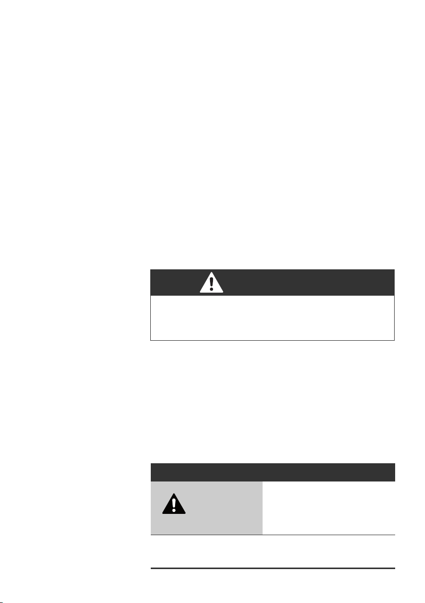
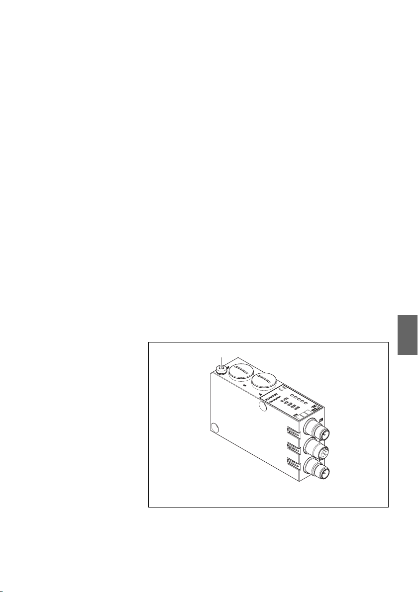
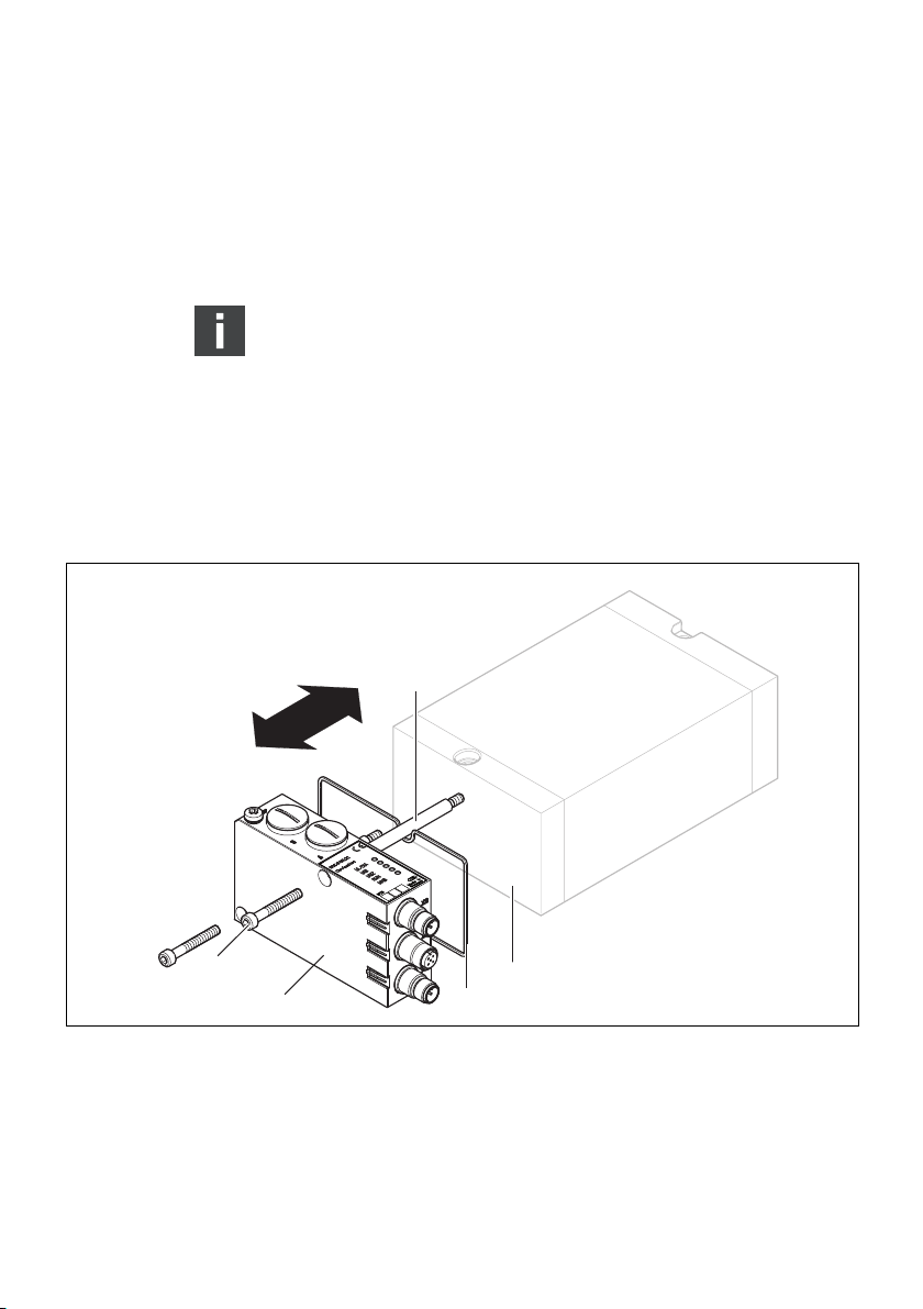
5.1 Gesamtübersicht Ventilsystem
Das Ventilsystem setzt sich, je nach Bestellumfang, aus den in
Abb. 1 dargestellten Komponenten zusammen:
Abb. 1: Gesamtübersicht: Beispielkonfiguration Buskoppler mit montiertem VS
1 DeviceNet-Buskoppler, B-Design
2 EP-Endplatte VS
1)
3 Ventilträger
1)
Mit eigener Betriebsanleitung
VS
AVENTICS | DeviceNet | R412009416–BDL–001–AC 15
3
7
8
4
5
6
9
1
2
Gerätebeschreibung
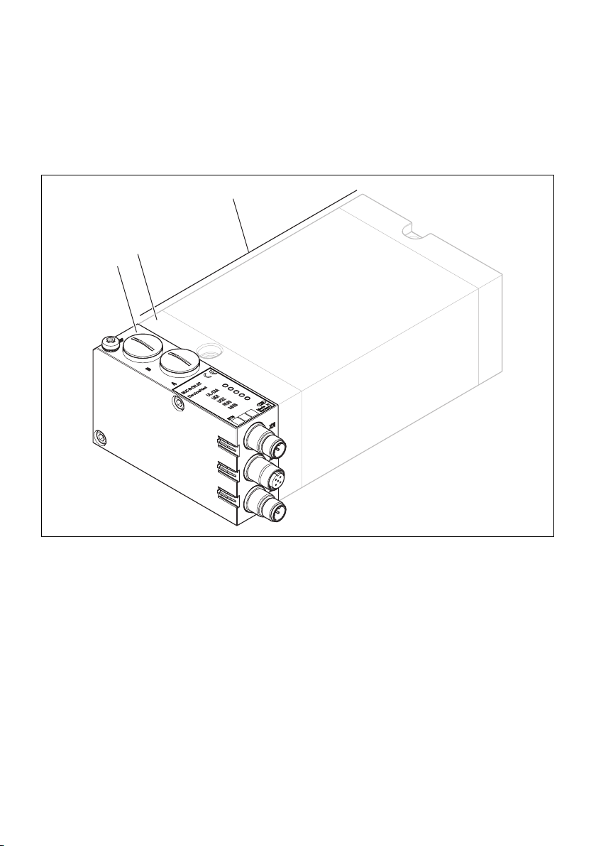
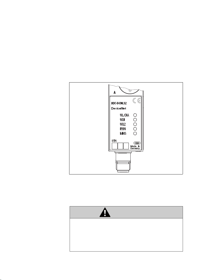
5.2 Gerätekomponenten
5.2.1 Buskoppler
Abb. 2: Übersicht zum Buskoppler
1 LED-Anzeigen für Diagnosemeldungen
2 BTN-Beschriftungsfeld
3 X71-Anschluss (BUS IN) für den Buskoppler zur Ansteuerung der Ventile
4
X72-Anschluss (BUS OUT) für den Buskoppler zur Ansteuerung weiterer DeviceNet-Slaves
5 X10-Anschluss (POWER) zur Spannungsversorgung der Ventilspulen
6 Schraubkappe A 0,6 + 0,2 Nm: Drehschalter S1, S2 (Einstellung Stationsadresse) und DIP-
Schalter S3 (Mode-Einstellung)
7
Schraubkappe B 0,6 + 0,2 Nm: Schiebeschalter S4 (Ventilzuordnung zur Versorgungsspannung)
8 FE-Anschluss 4 + 0,5 Nm
1)
9 Tasche für Einsteckschilder (siehe „Ersatzteile und Zubehör“ auf Seite 40
1)
Steckerbelegung siehe Seite 19 und Seite 21
Deutsch
1)

16 AVENTICS | DeviceNet | R412009416–BDL–001–AC
Gerätebeschreibung
Der Buskoppler ist ausschließlich für den Betrieb als
Teilnehmer an einem DeviceNet-Bus bestimmt.
DeviceNet-Adresse Die Adresse des Buskopplers wird über die beiden Drehschalter
S1 und S2 eingestellt.
Baudrate Die max. Baudrate beträgt 500 kBaud.
Diagnose Die Versorgungsspannungen für die Logik und die Ventil-
ansteuerung werden überwacht. Wenn die eingestellte
Schwelle der Ventilversorgungen unterschritten wird, wird ein
Diagnosesignal erzeugt und mittels Diagnose-LED und
Diagnoseinformation gemeldet.
Anzahl
ansteuerbarer
Ven til e
OSI Das Modell der DeviceNet-Kommunikation orientiert sich am
CAN Die unteren Schichten des Basic Reference Model basieren auf
DeviceNet Alle Vorgaben und Richtlinien zu DeviceNet sind den
Zertifizierung Das Gerät ist nach den Richtlinien des Conformance Test A19
Der Buskoppler verfügt über 32 Ventilausgänge. Damit ist die
Anzahl der max. ansteuerbaren Ventilspulen begrenzt.
Es können 16 beidseitig betätigte oder 32 einseitig betätigte
Ventile auf diese Weise angesteuert werden. Es ist auch eine
Kombination der Ventile möglich.
ISO/OSI Basic Reference Model.
Referenz:
W ISO 7498, 1984, Information Processing Systems – Open
System Interconnection – Basic Reference Model
CAN.
Spezifikationen der ODVA zu entnehmen.
von der ODVA zertifiziert.
Referenz:
W The CIP Network Library, Volume 1, Common Industrial
Protocol (CIP), Edition 3.3, November 2007
W The CIP Network Library, Volume 3, DeviceNet Adaption of
CIP, Edition 1.5, November 2007

AVENTICS | DeviceNet | R412009416–BDL–001–AC 17
135
A + 33
B + 33
33
Montage
6Montage
6.1 Buskoppler am Ventilsystem montieren
Sie erhalten Ihr individuell konfiguriertes Ventilsystem komplett
verschraubt mit allen Komponenten:
W Ventilträger
W Buskoppler
Die Montage des gesamten Ventilsystems ist in der
beiliegenden Betriebsanleitung für das VS ausführlich
beschrieben. Die Einbaulage des montierten VS ist beliebig.
Die Abmessungen des kompletten VS variieren je nach
Modulbestückung (siehe Abb. 3).
6.1.1 Abmessungen
Deutsch
Abb. 3: Maßzeichnung Ventilträger mit Buskoppler
Die Maße A und B sind abhängig vom verwendeten Ventilblock.
18 AVENTICS | DeviceNet | R412009416–BDL–001–AC
Montage
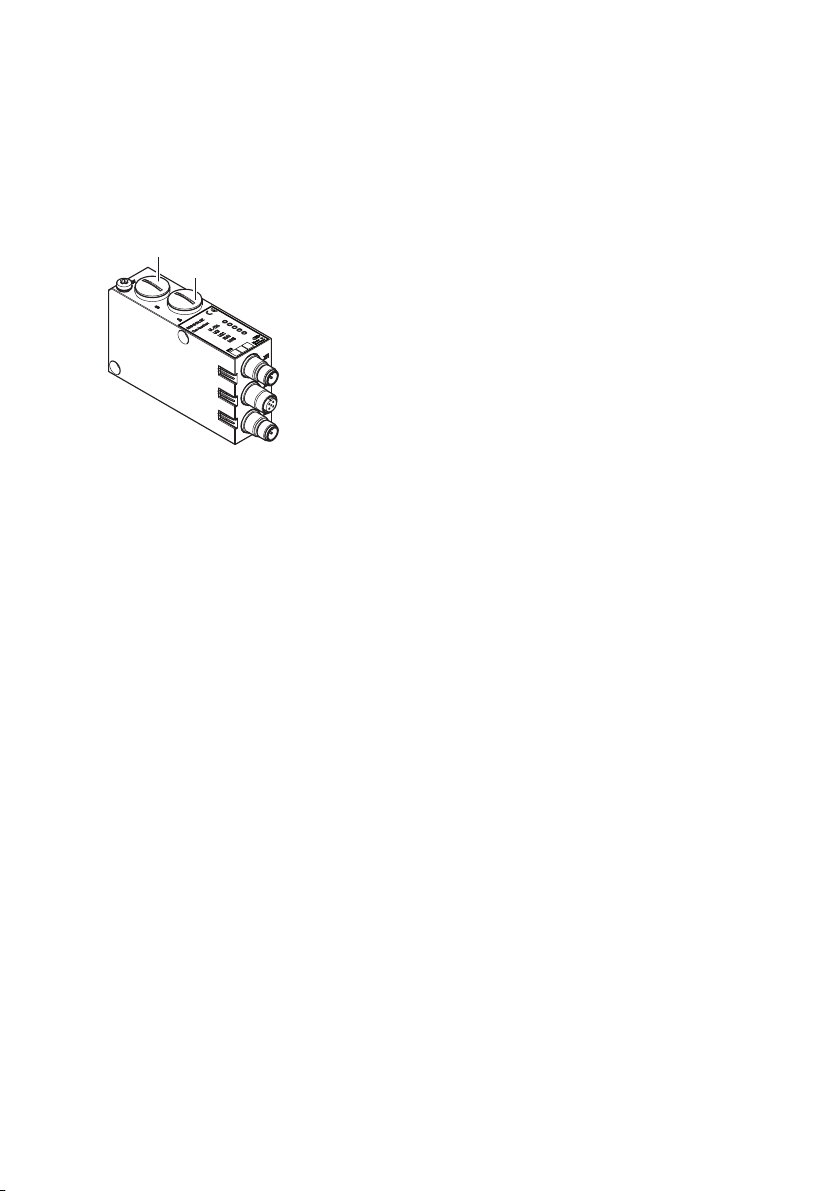
6.2 Module beschriften
Buskoppler O Beschriften Sie die für den Buskoppler vorgesehene/
verwendete Adresse am Buskoppler im Feld BTN.
Für die Kennzeichnung der Steckanschlüsse sind im Gehäuse
Einstecktaschen für Beschriftungsschilder (siehe „Ersatzteile
und Zubehör“ auf Seite 40) vorhanden.
Abb. 4: Beschriftungsfelder am Buskoppler
6.3 Buskoppler elektrisch anschließen
VORSICHT
Anliegende elektrische Spannung
Verletzungsgefahr durch elektrischen Schlag.
O Schalten Sie immer den betreffenden Anlagenteil
spannungsfrei und drucklos, bevor Sie am Ventilträger
Module elektrisch anschließen.

AVENTICS | DeviceNet | R412009416–BDL–001–AC 19
Montage
ACHTUNG
Falsche Verkabelung
Eine falsche oder fehlerhafte Verkabelung führt zu
Fehlfunktionen und zur Beschädigung des Bussystems.
O Halten Sie – sofern nicht anders angegeben – die
Aufbaurichtlinien der ODVA ein.
O Verwenden Sie nur Kabel, die den Spezifikationen des
Feldbusses sowie den Anforderungen bzgl.
Geschwindigkeit und Länge der Verbindung entsprechen.
O Montieren Sie Kabel und Stecker fachgerecht, damit
Schutzart, Schirmung und Zugentlastung gewährleistet
sind.
ACHTUNG
Stromfluss durch Potenzialunterschiede am Schirm
Über den Schirm des DeviceNet-Kabels dürfen
Potenzialunterschiede bedingten Ausgleichsströme fließen, da
dadurch die Schirmung aufgehoben wird und die Leitung sowie
der angeschlossene Buskoppler beschädigt werden können.
O Verbinden Sie gegebenenfalls die Massepunkte der
Anlage über eine separate Leitung mit ausreichendem
Querschnitt.
keine
durch
Deutsch
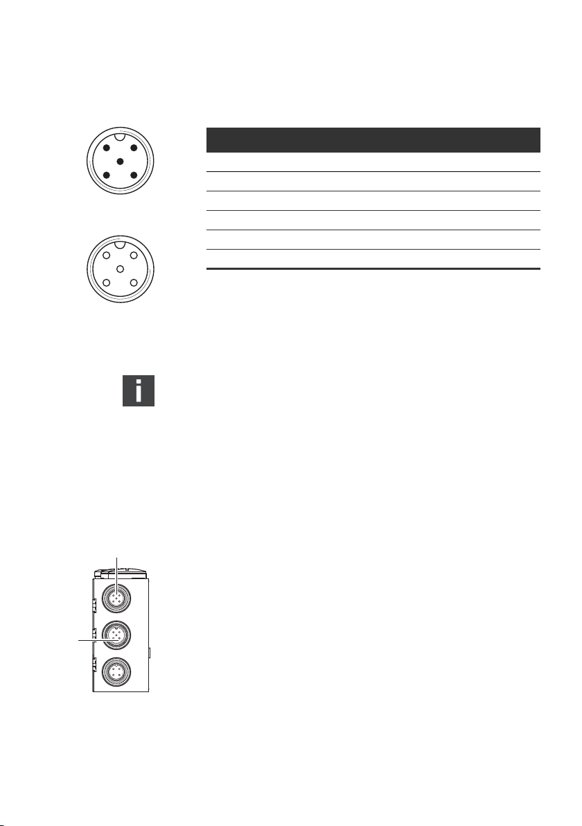
6.3.1 Allgemeine Hinweise zum Anschluss des
Buskopplers
Benutzen Sie für das Anschließen der Module konfektionierte
Steckverbindungen und Kabel.
O Verwenden Sie A-codierte Stecker für DeviceNet.
O Beachten Sie die in Tab. 5 dargestellte Pin-Belegung, wenn
Sie keine konfektionierten Steckverbindungen und Kabel
verwenden.
20 AVENTICS | DeviceNet | R412009416–BDL–001–AC
2
1
43
5
BUS IN
X71
2
3
4
1
5
X72
BUS OUT
Montage
Tabelle 5: Belegung X71 (BUS IN) und X72 (BUS OUT), M12, A-codiert
DeviceNet
Pin Signal Bedeutung
1 Drain Schirm über RC auf FE gelegt (intern)
1) 2)
2V+
1) 2)
3V-
24 V Busversorgung
Ground / 0V / GND-Busversorgung
4 CAN_H CAN_H bus linie (dominant high)
5 CAN_L CAN_L bus linie (dominant low)
Gehäuse Schirm- bzw. Funktionserde
1)
Die Versorgung des Buskopplers erfolgt über X10. Alle Leitungen sind
durchgeschleift. Der Buszustand von V+ und V- wird intern überprüft.
2)
Bei fehlender Belegung von V+ und V- leuchtet die LED-Fehleranzeige auf und
das Gerät bleibt im Initalisierungszustand. Achten Sie darauf, dass V+ und Vam Busstecker belegt sind.
Anschlusstechnik und Steckerbelegung entsprechen den
technischen Richtlinie der ODVA.
Bei Verwendung eines Kabels mit Beilauflitze kann diese
zusätzlich am Pin 1 der Busstecker (X71/X72) angeschlossen
werden.
6.3.2 Buskoppler als Zwischenstation anschließen
1
Seite 20) Ihrer Steckerverbindungen her, wenn Sie keine
konfektionierte Leitung verwenden.
1. Stellen Sie die korrekte Pin-Belegung (siehe Tab. 5 auf
X71
2
X72
X10
2. Schließen Sie die ankommende Busleitung an X71 (1) an.
3. Verbinden Sie die abgehende Busleitung über den Ausgang
X72 (2) mit dem nächsten Modul.
4. Schließen Sie den Schirm an beiden Seiten des Buskabels
direkt an das Steckergehäuse (EMV-Gehäuse) an, wenn Sie
nicht konfektionierte Kabel und Stecker mit Metallgehäuse
verwenden. So schützen Sie die Datenleitungen gegen
Störungseinkopplungen.
Stellen Sie sicher, dass das Steckergehäuse fest mit dem
Buskoppler-Gehäuse verbunden ist.
AVENTICS | DeviceNet | R412009416–BDL–001–AC 21
X71
X72
X10
1
2
2
1
43
POWER
X10
Montage
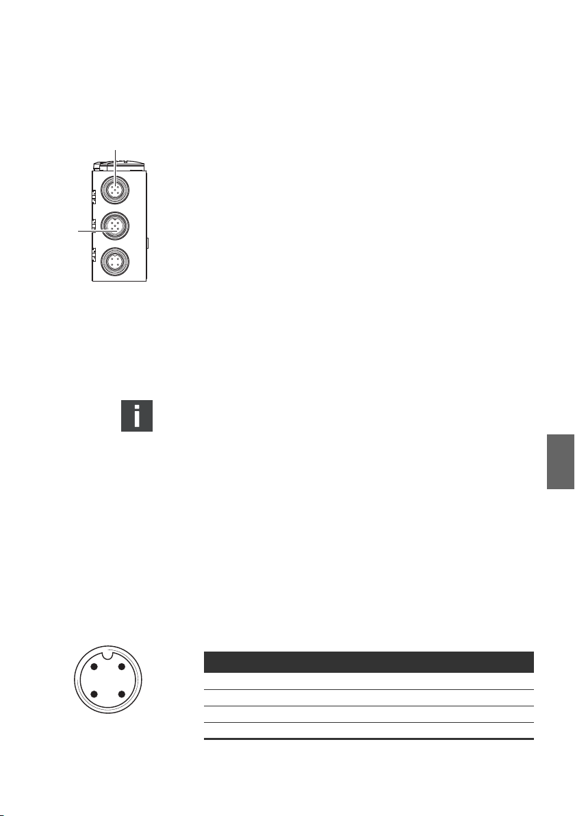
6.3.3 Buskoppler als letzte Station anschließen
1. Stellen Sie die korrekte Pin-Belegung (siehe Tab. 5 auf
Seite 20) Ihrer Steckerverbindungen her, wenn Sie keine
konfektionierte Leitung verwenden.
2. Schließen Sie die ankommende Busleitung an X71 (1) an.
3. Versehen Sie die Gerätedose X72 (BUS OUT) mit einem
DeviceNet-Abschlussstecker (siehe Kapitel „Ersatzteile und
Zubehör“ auf Seite 40).
4. Schließen Sie den Schirm an beiden Seiten des Buskabels
direkt an das Steckergehäuse (EMV-Gehäuse) an, wenn Sie
nicht konfektionierte Kabel und Stecker mit Metallgehäuse
verwenden. So schützen Sie die Datenleitungen gegen
Störungseinkopplungen. Stellen Sie sicher, dass das
Steckergehäuse fest mit dem Buskopplergehäuse
verbunden ist.
Zur Vermeidung von Ausgleichsströmen über den Schirm
des Buskopplers ist zwischen den Geräten einer Potentialausgleichsleitung von mindestens 10 mm
2
erforderlich.
6.3.4 Logik- und Lastversorgung Buskoppler
Deutsch
anschließen
Über den Gerätestecker X10 (POWER) werden die Ventile und
der Buskoppler versorgt.
Wenn Sie die Logik- und Lastversorgung des Buskopplers
anschließen, müssen Sie die in Tab. 6 dargestellte Pin-Belegung
sicherstellen.
Tabelle 6: Belegung des Gerätesteckers X10 (POWER), M12, A-codiert
Pin X10 Belegung
1)
Beide Versorgungsspannungen (Pin2, Pin4) müssen mit einer externen
Sicherung (3A, F) abgesichert werden.
DeviceNet
1U
2U
3 OV Masse für UL, UQ1 und U
4UQ2Spannungsversorgung Ventile1)
Spannungsversorgung Buskoppler-Logik
L
Spannungsversorgung Ventile1)
Q1
Q2
22 AVENTICS | DeviceNet | R412009416–BDL–001–AC
Montage
, UQ1 und UQ2 sind galvanisch miteinander verbunden.
W U
L
W Über die Ventilversorgung U
byteweise (entspricht je 4 beidseitig betätigten Ventilen oder
8 einseitig betätigten Ventilen) abgeschaltet werden.
W Die Zuordnung der Ventilgruppen (4 oder 8 Ventile) erfolgt
über die Schiebeschalter S4 (siehe „Ventilversorgung
auswählen“ auf Seite 27). Dadurch ist z. B. eine separate
Abschaltung möglich.
Das Kabel für die Lastversorgung muss folgende
Anforderungen erfüllen:
W Kabelbuchse: 4-polig, A-codiert ohne Mittelloch
W Leitungsquerschnitt an Gesamtstrom und Leitungslänge
anpassen: je Ader ≥ 0,5 mm
W Länge: max. 20 m
Tabelle 7: Stromaufnahme an X10 (POWER) am Buskoppler
Signal Belegung Gesamtstrom
U
U
U
Logik max. 0,5 A
L
Ventile max. 3 A
Q1
Ventile max. 3 A
Q2
Q1
2
und U
können die Ventile
Q2
VORSICHT
Gefährliche Spannungen
Ein Netzteil mit nicht sicherer Trennung kann im Fehlerfall zu
gefährlichen Spannungen führen. Verletzungen durch
Stromschlag und Schädigung des Systems können die Folgen
sein.
O Verwenden Sie nur ein Netzteil mit einer sicheren
Trennung nach EN 60747, Klassifikation VDE 0551! Damit
gelten die entsprechenden Stromkreise als SELV/PELVStromkreise nach IEC 60364-4-41.
AVENTICS | DeviceNet | R412009416–BDL–001–AC 23
Montage
So schließen Sie die Lastversorgung des Buskopplers an:
1. Stellen Sie die korrekte Pin-Belegung (siehe Tab. 6 auf
Seite 21) Ihrer Steckerverbindungen her, wenn Sie keine
konfektionierte Anschlussleitung verwenden.
2. Schließen Sie mit dem Steckerverbinder (siehe „Ersatzteile
und Zubehör“ auf Seite 40) die Betriebsspannungen an den
Buskoppler an.
3. Kontrollieren Sie die Spezifikationen der
Betriebsspannungen anhand der elektrischen Kenngrößen
und halten Sie diese ein (siehe Kapitel „Technische Daten“
auf Seite 39).
4. Stellen Sie die Leistungen gemäß Tab. 7, Seite 22 bereit.
Wählen Sie die Kabelquerschnitte entsprechend der
Kabellänge und der auftretenden Ströme.
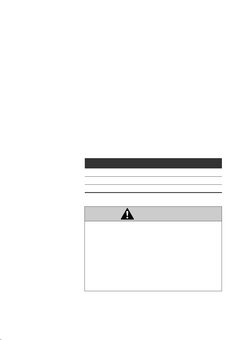
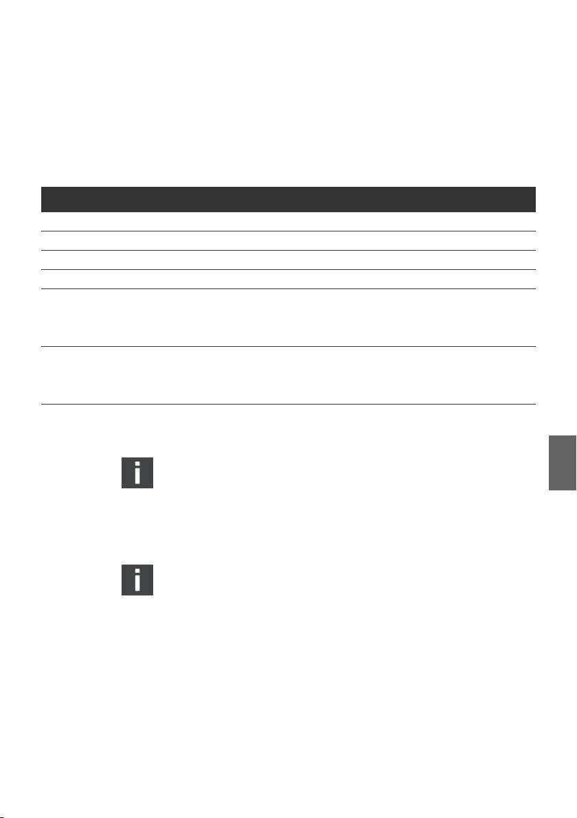
6.3.5 FE-Anschluss
Erdung am Buskoppler O Verbinden Sie zur Ableitung von EMV-Störungen den FE-
Anschluss (1) am Buskoppler über eine niederimpedante
Leitung mit der Funktionserde.
Empfohlener Kabelquerschnitt: 10 mm
1
2
Deutsch
Abb. 5: FE-Anschluss am Buskoppler (1)
24 AVENTICS | DeviceNet | R412009416–BDL–001–AC
A
B
Inbetriebnahme und Bedienung
7 Inbetriebnahme und Bedienung
7.1 Voreinstellungen vornehmen
Folgende Voreinstellungen müssen Sie durchführen:
W Adresse am Buskoppler einstellen
W Ventilversorgung auswählen
W Baudrate einstellen
W Diagnosemeldungen einstellen
Alle diese Einstellungen erfolgen über die Schalter unter den
beiden Verschraubungen A und B.
Gehen Sie bei allen Voreinstellungen wie folgt vor:
1. Drehen Sie die entsprechenden Verschraubungen ab.
2. Nehmen Sie die entsprechende Einstellung wie nachfolgend
beschrieben vor.
3.
Drehen Sie die Verschraubungen wieder ein (0,6 + 0,2 Nm).
Achten Sie hierbei auf den korrekten Sitz der Dichtungsringe.
7.1.1 Baudrate einstellen
Die Baudrate wird am Schalter S3 eingestellt (siehe Tab. 8 auf
Seite 25). Er befindet sich unter der Verschraubung A.
1. Öffnen Sie die Verschraubung A.
2. Stellen Sie die Baudrate (Übertragungsrate) mit dem
Schalter S3.1 bis S3.3 gemäß den Angaben aus Tab. 8 auf
Seite 25 ein.
Auslieferungszustand: 125 kBaud
AVENTICS | DeviceNet | R412009416–BDL–001–AC 25
0
9
8
7
6
5
4
3
2
1
0
9
8
7
6
5
4
3
2
1
S1
S2
S3
Inbetriebnahme und Bedienung
Tabelle 8: S3, Schalterbelegung zur Baudrateneinstellung
Baudrate max. Leitungslänge S3.3 S3.2 S3.1
reserviert ON ON ON
reserviert ON ON OFF
reserviert ON OFF ON
reserviert ON OFF OFF
reserviert OFF ON ON
500 kbit/s 100 m OFF ON OFF
250 kbit/s 250 m OFF OFF ON
1)
125 kbit/s
1)
Default-Einstellung
500 m OFF OFF OFF
7.1.2 Adresse am Buskoppler einstellen
Die Stationsadresse wird mit Hilfe der beiden Schalter S1 und
S2 (siehe Abb. 6) eingestellt.
Deutsch
Abb. 6: Adressschalter S1, S2 und Mode-Schalter S3 am Buskoppler
Die beiden Drehschalter S1 und S2 für die Stationsadresse des
Ventilsystems im DeviceNet befinden sich unter der
Verschraubung A.
O
Vergeben Sie mit S1 und S2 (siehe Abb. 6) die
Stationsadresse von 0 bis 63 frei (die Maximale MAC-ID ist 63):
– S1: Einerstellen von 0 bis 9
– S2: Zehnerstellen von 0 bis 9
– S1 + S2 = Stationsadresse
Auslieferungszustand: MAC-ID = 63

26 AVENTICS | DeviceNet | R412009416–BDL–001–AC
Inbetriebnahme und Bedienung
7.1.3 Diagnosemeldungen einstellen
Der Mode-Schalter S3 für die Einstellung der
Diagnosemeldungen befindet sich unter der
PG-Verschraubung A (siehe Abb. 6 auf Seite 25).
Der Auslieferungszustand ist DeviceNet-konform.
Die Diagnose ist deaktiviert (S3.5 auf OFF).
O Aktivieren oder deaktivieren Sie mit dem Schalter S3.5 die
Diagnosemeldung an den Master.
Die geänderte Schalterstellung wird erst nach einem
erneuten „Power-on“ aktiviert.
Diese Einstellung kann auch über das Module Control
Object zugewiesen werden. Bei Zuweisung über das
Module Control Object wird die Stellung von 3.5
wirkungslos. Änderungen über das Module Control Object
werden erst nach einem STOPP/START wirksam.
Auch bei ausgeschalteter Diagnosemeldung an den Master
werden anstehende Diagnosen auf den LEDs angezeigt.
Tabelle 9: S3, Überwachungsschwelle für Ventilspannung festlegen
Bit Schalterstellung Funktion
3.1 OFF (default) / ON Baudrate (siehe Tab. 8 auf Seite 25)
3.2 OFF (default) / ON Baudrate (siehe Tab. 8 auf Seite 25)
3.3 OFF (default) / ON Baudrate (siehe Tab. 8 auf Seite 25)
3.4 OFF (default)
ON
3.5 OFF (default)
ON
3.6 OFF (default) / ON NC
3.7 OFF (default) / ON NC
3.8 OFF (default) / ON NC
Schwelle für U
Schwelle für U
Diagnosemeldung deaktiviert
Diagnosemeldung aktiviert
und UQ2 ist 21,6V (10%)
Q1
und UQ2 ist 20,4V (15%)
Q1

AVENTICS | DeviceNet | R412009416–BDL–001–AC 27
4321
DCBA
S4.4
S4.1
1*
2*
* Schalterstellung
Inbetriebnahme und Bedienung
7.1.4 Umschalten der Toleranzpegel der
Ventilversorgung U
Für unterschiedliche Ventilserien kann die Schwelle 20,4 V und
21,6 V angepasst werden (siehe Tab. 9 auf Seite 26). Im
Auslieferungszustand ist die Schwelle auf 21,6 V (10 %)
eingestellt (S3.4 auf OFF). Sinkt die Versorgungsspannung für
die Ventilsteuerung unter diese Schwelle, wird eine
Diagnosemeldung erzeugt.
und U
Q1
Q2
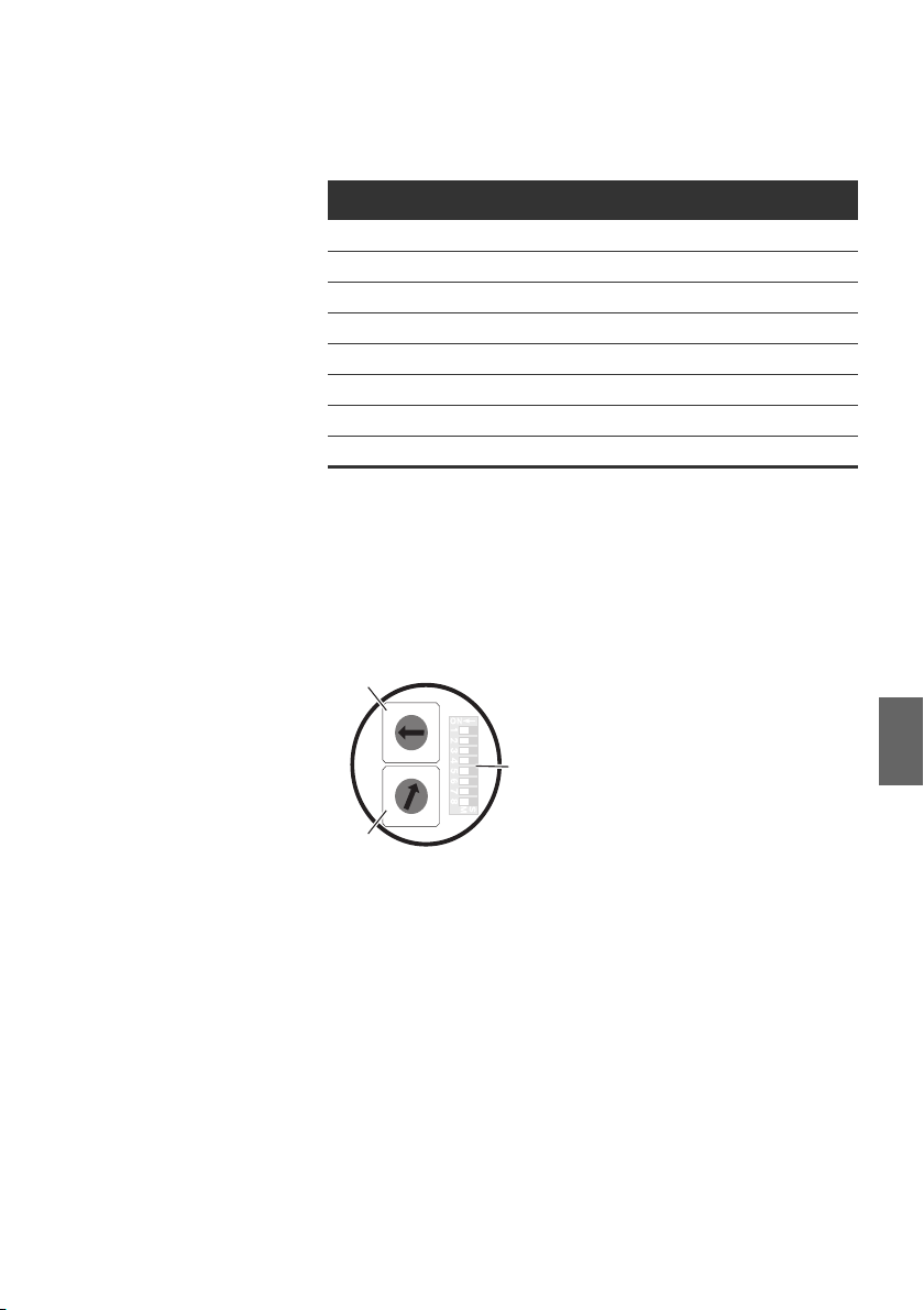
7.1.5 Ventilversorgung auswählen
Mit dem Schiebeschalter S4 (unter Verschraubung B) kann die
Ventilspannungsversorgung blockweise ausgewählt werden.
Es kann zwischen den Spannungen U
externen Versorgung von X10 umgeschaltet werden.
und UQ2 aus der
Q1
Alle Schalter befinden sich im Auslieferungszustand in der
Deutsch
Stellung 1.
ACHTUNG
Spannung an Schaltern
Schalter können beschädigt werden, wenn bei ihrer Bedienung
eine Spannung anliegt.
O Betätigen Sie die Schalter nur in spannungsfreiem
Zustand!
O Wählen Sie die Schalterstellung von S4 gemäß
nachfolgender Tabelle.

28 AVENTICS | DeviceNet | R412009416–BDL–001–AC
Inbetriebnahme und Bedienung
Tabelle 10: Zuordnung der Schalter S4
Schieber Funktion Schalterstellung 1 Schalterstellung 2
4.1 Spannungsversorgung
Ansteuerbyte 1
4.2 Spannungsversorgung
Ansteuerbyte 2
4.3 Spannungsversorgung
Ansteuerbyte 3
4.4 Spannungsversorgung
Ansteuerbyte 4
U
(externe Versorgung,
(externe Versorgung,
(externe Versorgung,
(externe Versorgung,
Q1
PIN 2, weiß)
U
Q1
PIN 2, weiß)
U
Q1
PIN 2, weiß)
U
Q1
PIN 2, weiß)
U
(externe Versorgung,
(externe Versorgung,
(externe Versorgung,
(externe Versorgung,
Q2
PIN 4, schwarz)
UQ2
PIN 4, schwarz)
UQ2
PIN 4, schwarz)
UQ2
PIN 4, schwarz)
ACHTUNG
Spannung an Schaltern
Schalter können beschädigt werden, wenn bei ihrer Bedienung
eine Spannung anliegt.
O
Betätigen Sie die Schalter nur in spannungsfreiem Zustand!
So ordnen Sie die Ventilversorgung zu:
1.
Öffnen Sie die SchraubkappeB (siehe Abbildung auf Seite 24).
2. Ordnen Sie mit Hilfe des Schalters S4 jeder Ventilgruppe
eine der beiden Versorgungsspannungen U
oder UQ2 zu
Q1
(siehe Abbildung auf Seite 27 und 10).
AVENTICS | DeviceNet | R412009416–BDL–001–AC 29
Inbetriebnahme und Bedienung
Für die Zuordnung des Schalters S4 und der Versorgung
montierter Ventile finden Sie die Beispiele für 32 Ventilspulen in
den Tab. 11 und Tab. 12 auf den Seiten 30 und 31 (jeweils
Beispiele 1 bis 3/Beispiele 4 bis 6). Darin sind folgende
Beispielkombinationen aufgeführt:
Beispiele
Beispiel 1 Anschlussplatten für beidseitig betätigte Ventile beidseitig betätigte Ventile
Beispiel 2 Anschlussplatten für beidseitig betätigte Ventile einseitig betätigte Ventile
Beispiel 3 Anschlussplatten für beidseitig betätigte Ventile ein- und beidseitig betätigte Ventile
Beispiel 4 Anschlussplatten für einseitig betätigte Ventile einseitig betätigte Ventile
Beispiel 5 Anschlussplatten für beidseitig betätigte Ventile beidseitig betätigte Ventile
Beispiel 6 Anschlussplatten für beidseitig betätigte Ventile ein- und beidseitig betätigte Ventile
1)
1)
Verwendete Anschlussplatten Ventilbestückung
kombiniert mit
Anschlussplatten für einseitig betätigte Ventile einseitig betätigte Ventile
kombiniert mit
Anschlussplatten für einseitig betätigte Ventile einseitig betätigte Ventile
Entsprechend Ihren Anforderungen können Sie auch andere Kombinationen wählen.
Von der elektrischen Anschlussseite aus betrachtet
müssen zuerst die Anschlussplatten für beidseitig betätigte
Ventile und danach die für einseitig betätigte Ventile
angeordnet werden. Die maximale Spulenzahl bezogen auf
alle Anschlussplatten beträgt 32.
Die Zuordnung von Schaltern und Ventilversorgungen
ändert sich beim Einsatz von Modulerweiterungen (siehe
Betriebsanleitung R412008961). Dies gilt auch für die
folgenden Beispiele in Tab. 11 und Tab. 12.
Deutsch

30 AVENTICS | DeviceNet | R412009416–BDL–001–AC
Inbetriebnahme und Bedienung
Tabelle 11: Beispiele für die Zuordnung von Schaltern und Ventilversorgung, 32 Ventilspulen
Beispiel 1 Beispiel 2 Beispiel 3
Anschlussplatte für beidseitig betätigte Ventile
Byte
Schalter
S4.1 0 A0.0
A0.1 12 – 12
A0.2
A0.3 12 – 12
A0.4
A0.5 12 – 12
A0.6
A0.7 12 – 12
S4.2 1 A1.0
A1.1 12 – 12
A1.2
A1.3 12 – –
A1.4
A1.5 12 – –
A1.6
A1.7 12 – –
S4.3 2 A2.0
A2.1 12 –
A2.2
A2.3 12 – 12
A2.4
A2.5 12 – 12
A2.6
A2.7 12 – –
Ven til-
Adresse
platz
1
2
3
4
5
6
7
8
9
10
11
12
1)
Spule LED
14
14
14
14
14
14
14
14
14
14
14
14
S4.4 3 A3.0 13 14
A3.1 12 – –
A3.2 14 14
A3.3 12 – 12
A3.4 15 14
A3.5 12 – 12
A3.6 16 14
A3.7 12 – –
1)
Weiße Felder kennzeichnen Ventilplätze mit beidseitig betätigten Ventilen.
Grau unterlegte Felder kennzeichnen Ventilplätze mit einseitig betätigten Ventilen.
Ven til platz
1
2
3
4
5
6
7
8
9
10
11
12
13
14
15
16
1)
Spule LED
14
14
14
14
14
14
14
14
14
14
14
14
14
14
14
14
Ven tilplatz
1
2
3
4
5
6
7
8
9
10
11
12
13
14
15
16
1)
Spule LED
14
14
14
14
14
14
14
14
14
14
14
14
14
14
14
14

AVENTICS | DeviceNet | R412009416–BDL–001–AC 31
Inbetriebnahme und Bedienung
Tabelle 12: Beispiele für die Zuordnung von Schaltern und Ventilversorgung, 32 Ventilspulen
Beispiel 4 Beispiel 5 Beispiel 6
Anschlussplatte für
einseitig betätigte Ventile
Byte
Schalter
S4.1 0 A0.0
A0.1
A0.2
A0.3
A0.4
A0.5
A0.6
A0.7
S4.2 1 A1.0
A1.1
A1.2
A1.3
A1.4
A1.5
A1.6
A1.7
S4.3 2 A2.0
A2.1
A2.2
A2.3
A2.4
A2.5
A2.6
A2.7
S4.4 3 A3.0
A3.1
A3.2
A3.3
A3.4
A3.5
A3.6
A3.7
1)
Weiße Felder kennzeichnen Ventilplätze mit beidseitig betätigten Ventilen.
Grau unterlegte Felder kennzeichnen Ventilplätze mit einseitig betätigten Ventilen.
Ven til-
Adresse
platz
1)
Spule LED
114
214 12 12
314
414 12 –
514
614 12 –
714
814 12 12
914514
10 14 614 12
11 14 714
12 14 814 12
13 14 914714
14 14 10 14 814
15 14 11 14 914
16 14 12 14 10 14
17 14 13 14 11 14
18 14 14 14 12 14
19 14 15 14 13 14
20 14 16 14 14 14
21 14 17 14 15 14
22 14 18 14 16 14
23 14 19 14 17 14
24 14 20 14 18 14
25 14 21 14 19 14
26 14 22 14 20 14
27 14 23 14 21 14
28 14 24 14 22 14
29 14 25 14 23 14
30 14 26 14 24 14
31 14 27 14 25 14
32 14 28 14 26 14
Anschlussplatte für ein- und beidseitig betätigte
Ven tile
Ven til -
platz
1
2
3
4
1)
Spule LED
14
14
14
14
Ven tilplatz
1
2
3
4
1)
5
6
Spule LED
14
14
14
14
14
14
Deutsch

32 AVENTICS | DeviceNet | R412009416–BDL–001–AC
Inbetriebnahme und Bedienung
7.2 Bussystem konfigurieren
Die in diesem Abschnitt dargestellten Konfigurierungsschritte
sind den bereits beschriebenen Einstellungen am Buskoppler
(siehe „Voreinstellungen vornehmen“ auf Seite 24)
übergeordnet und Teil der Busmasterkonfiguration des
Gesamtsystems.
Die beschriebenen Arbeiten dürfen nur von einer Elektronikfachkraft und unter Beachtung der Dokumentation des
Betreibers zur Konfiguration des Busmasters sowie der
geltenden technischen Normen, Richtlinien und
Sicherheitsvorschriften durchgeführt werden.
Vor der Konfiguration müssen Sie folgende Arbeiten am
Buskoppler durchgeführt und abgeschlossen haben:
W Sie haben den Buskoppler und den Ventilträger montiert
(siehe „Montage“ auf Seite 17).
W
Sie haben den Buskoppler angeschlossen (siehe „Buskoppler
elektrisch anschließen“ auf Seite 18).
W Sie haben die Voreinstellungen vorgenommen
(siehe „Voreinstellungen vornehmen“ auf Seite 24).
ACHTUNG
Konfigurationsfehler
Ein fehlerhaft konfigurierter Buskoppler kann zu
Fehlfunktionen im System führen und eine Schädigung des
Systems zur Folge haben.
O Die Konfiguration darf daher nur von einer
Elektronikfachkraft durchgeführt werden!
O Konfigurieren Sie das Bussystem gemäß Ihren
Systemanforderungen, den Vorgaben des Herstellers und
allen geltenden technischen Normen, Richtlinien und
Sicherheitsvorschriften. Beachten Sie dabei die
Dokumentation des Betreibers zur Konfiguration
des Busmasters.

AVENTICS | DeviceNet | R412009416–BDL–001–AC 33
Inbetriebnahme und Bedienung
Das Betriebsverhalten, die relevanten Objekte und Parameter
zur Konfiguration des Buskopplers, mögliche Einstellungen als
Beispiele sowie der Funktionsumfang sind im Kapitel „Anhang
Angaben zur Busmaster-konfiguration mit DeviceNet“ ab
Seite 41 aufgeführt.
7.3 Test und Diagnose an den Modulen
7.3.1 Diagnoseanzeige am Buskoppler ablesen
Die LEDs auf der Frontplatte des Buskopplers geben die in
Tab. 13 aufgeführten Meldungen wieder.
O Überprüfen Sie vor Inbetriebnahme und während des
Betriebs regelmäßig die Buskopplerfunktionen durch
Ablesen der Diagnoseanzeigen.
Tabelle 13: Bedeutung der Diagnose-LEDs am Buskoppler
LED Signal Beschreibung
/DIA grün Logikversorgung vorhanden
U
L
rot Überlast Geberversorgung (Sammeldiagnose)
aus keine Logikversorgung vorhanden
U
Q1
U
Q2
grün Ventilversorgung UQ1 in Ordnung
rot Unterspannung (12 V < U
aus Ventilversorgung U
< 21,6 V/20,4 V (S3.4))
Q1
< 12 V
Q1
grün Ventilversorgung UQ2 in Ordnung
rot Unterspannung (12 V < U
aus Ventilversorgung U
< 21,6 V/20,4 V (S3.4))
Q2
< 12 V
Q2
RUN grün Initialisierung beendet (Operativer Zustand).
RUN
+UL
RUN
+MNS
UL
RUN blinkt grün
+MNS aus
grün
aus
blinkt rot
blinkt grün
Initialisierung nach Power-on
2)
Busversorung (V+/V-) fehlt, Gerät bleibt im Initialisierungszusstand
4)
3)
Unzulässige Mac-ID (>63) oder Duplicate Mac-ID-Fehler
MNS rot
1) Diese Anzeige erfolgt nur, solange der überlastete Ausgang angesteuert bzw. der max. Summenstrom der
Geberversorgung überschritten wird.
2) Blinkfrequenz 1 0,5 s an / 0,5 s aus
3) Blinkfrequenz 2 0,125 s an / 0,125 s aus
4) Blinkfrequenz 3 0,8 s an / 0,2 s aus
1)
Deutsch

34 AVENTICS | DeviceNet | R412009416–BDL–001–AC
Inbetriebnahme und Bedienung
Die Funktion der MNS LED entspricht den Vorgaben der ODVA
(siehe Spec.: "The CIP NETWORKS LIBRARAY Volume Three:
DeviceNet™ Adaptation of CIPEdition 1.5, November 2007")
7.4 VS mit Buskoppler in Betrieb nehmen
Bevor Sie das System in Betrieb nehmen, müssen Sie folgende
Arbeiten durchgeführt und abgeschlossen haben:
W Sie haben den Ventilträger und den Buskoppler montiert
(siehe „Buskoppler am Ventilsystem montieren“ auf
Seite 17).
W Sie haben den Buskoppler angeschlossen (siehe
„Buskoppler elektrisch anschließen“ auf Seite 18).
W Sie haben die Voreinstellungen und die Konfiguration
durchgeführt (siehe „Voreinstellungen vornehmen“ auf
Seite 24).
W Sie haben den Busmaster so konfiguriert, dass die Ventile
richtig angesteuert werden.
Die Inbetriebnahme und Bedienung darf nur von einer
Elektro- oder Pneumatikfachkraft oder von einer
unterwiesenen Person unter der Leitung und Aufsicht einer
Fachkraft erfolgen (siehe „Qualifikation des Personals“ auf
Seite 9).

AVENTICS | DeviceNet | R412009416–BDL–001–AC 35
Inbetriebnahme und Bedienung
VORSICHT
Unkontrollierte Bewegungen der Aktoren beim Einschalten
der Pneumatik
Es besteht Verletzungsgefahr, wenn sich das System in einem
undefinierten Zustand befindet und wenn die
Handhilfsbetätigungen auf Position „1“ stehen.
O Bringen Sie das System in einen definierten Zustand,
bevor Sie es einschalten!
O Stellen Sie alle Handhilfstbetätigungen auf Position „0“.
O Stellen Sie sicher, dass sich keine Person innerhalb des
Gefahrenbereichs befindet, wenn Sie die
Druckluftversorgung einschalten.
O Beachten Sie auch die entsprechenden Anweisungen und
Warnhinweise der Betriebsanleitung Ihres VS.
1. Schalten Sie die Betriebsspannung ein.
2. Überprüfen Sie die LED-Anzeigen an allen Modulen.
3. Schalten Sie die Druckluftversorgung ein.
Deutsch
36 AVENTICS | DeviceNet | R412009416–BDL–001–AC
Demontage und Austausch
8 Demontage und Austausch
Sie können den Buskoppler je nach Bedarf austauschen.
Die Gewährleistung von AVENTICS gilt nur für die
ausgelieferte Konfiguration und Erweiterungen, die bei der
Konfiguration berücksichtigt wurden. Nach einem Umbau,
der über diese Erweiterungen hinausgeht, erlischt die
Gewährleistung.
8.1 Buskoppler austauschen
4
1
2
Abb. 7: Buskoppler an einem VS austauschen
1 Innensechskantschrauben M5x35, 3 + 0,5 Nm 4 Zuganker
2 Buskoppler 5 EP-Endplatte VS
3 Dichtung
5
3
AVENTICS | DeviceNet | R412009416–BDL–001–AC 37
Demontage und Austausch
VORSICHT
Anliegende elektrische Spannung und hoher Druck
Verletzungsgefahr durch elektrischen Schlag und plötzlichen
Druckabbau.
O Schalten Sie das System drucklos und spannungsfrei.
O Beachten Sie beim Umgang mit ESD-empfindlichen
Baugruppen die vorgeschriebenen
Vorsichtsmaßnahmen.
So tauschen Sie das Modul aus:
1.
Trennen Sie die elektrischen Anschlüsse vom Buskoppler (4).
2. Lösen Sie den Buskoppler (2)
(je 2 Innensechskantschrauben DIN 912 – M4 (1),
Schlüsselweite 3).
3. Ziehen Sie den Buskoppler (2) von der EP-Endplatte (4) ab.
4. Schieben Sie den neuen Buskoppler (4) auf die EP-Endplatte
(4) auf.
5. Stellen Sie sicher, dass die Dichtung (3) richtig eingelegt ist.
6. Schrauben Sie den Buskoppler (2) an
(je 2 Innensechskantschrauben DIN 912 – M4 (1),
Schlüsselweite 3). Anzugsdrehmoment: 3,0 + 0,5 Nm.
7. Führen Sie alle Voreinstellungen am neuen Buskoppler (4)
durch (siehe „Voreinstellungen vornehmen“ auf Seite 24).
8. Stellen Sie die Anschlüsse wieder her.
9. Überprüfen Sie die Konfiguration und passen Sie diese
gegebenenfalls an (siehe „Bussystem konfigurieren“ auf
Seite 32).
Deutsch

38 AVENTICS | DeviceNet | R412009416–BDL–001–AC
Pflege und Wartung
9 Pflege und Wartung
VORSICHT
Anliegende elektrische Spannung und hoher Druck
Verletzungsgefahr durch elektrischen Schlag und plötzlichen
Druckabbau.
O Schalten Sie das System vor der Durchführung von
Pflege- und Wartungsarbeiten drucklos und
spannungsfrei.
9.1 Module pflegen
ACHTUNG
Beschädigung der Gehäuseoberfläche durch Lösemittel und
aggressive Reinigungsmittel!
Die Oberflächen und Dichtungen können durch Lösemittel oder
aggressive Reinigungsmittel beschädigt werden.
O Verwenden Sie niemals Lösemittel oder aggressive
Reinigungsmittel!
O Reinigen Sie das Gerät regelmäßig mit einem feuchten
Lappen. Verwenden Sie dazu nur Wasser oder ein mildes
Reinigungsmittel.
9.2 Module warten
Die Buskoppler des VS sind wartungsfrei.
O Beachten Sie die Wartungsintervalle und Vorgaben der
Gesamtanlage.

AVENTICS | DeviceNet | R412009416–BDL–001–AC 39
Technische Daten
10 Technische Daten
10.1 Kenngrößen
Allgemein
Schutzart nach EN 60 529 /
IEC 529 IP65 im montierten Zustand
Umgebungstemperatur
W Betrieb
W Lagerung
Elektromagnetische Verträglichkeit
Störfestigkeit EN 61000-6-2
Störaussendung EN 61000-6-4
U
10.2 Buskoppler
0C bis +50°C ohne Betauung
–20°C bis +70°C
Elektrik
Betriebsspannung
W Logik
–U
L
–I
L
–Absicherung der Logikspannung 500 mAF
W Last U
Leitungslänge der Spannungsversorgung max. 20 m
Maximaler Strom in der 0-V-Leitung 4 A
Spannungsabfall intern 0,6 V
Max. Ausgangsstrom je Ventilausgang 100 mA
Anzahl der Ausgänge max. 32
Anzahl der Ausgangsbytes fest 4 Byte Ausgang und 0 Byte Eingang
Hochlaufzeit ca. 1 s
, U
Q1
Q2
–Absicherung der Spannungsversorgung 2 x 3,0 AF
Schutzkleinspannung (SELV/PELV) nach IEC 60364-4-41
24 V DC (+20%/–15 %)
50 mA
24 V DC (10%/15%)
Restwelligkeit 0,5%
Deutsch

40 AVENTICS | DeviceNet | R412009416–BDL–001–AC
Ersatzteile und Zubehör
11 Ersatzteile und Zubehör
11.1 Buskoppler
Bestellnummer
VS-Buskoppler für DeviceNet mit Ansteuerung für 32 Ventilspulen
Zubehör
Satz: Dichtung, 2 Schrauben M5, 1 Schraube FE R412008885
10x Verschlussschraube metrisch R412008886
5x Karten-Einsteckschilder R412008887
DeviceNet-Abschlussstecker 8941054264
Datenstecker
DeviceNet
M12x1 Schutzkappe 1823312001
1)
Lieferung inkl. 2 Innensechskantschrauben, Dichtung und Handbuch
Dateneingangsstecker,
Buchse M12x1, 5-polig gerade,
A-codiert, Leitungs-Ø 6 – 8 mm
Datenausgangsstecker,
Stift M12x1, 5-polig gerade,
A-codiert, Leitungs-Ø 6 – 8 mm
1)
R412008539
8942051602
8942051612
11.2 Power-Stecker für Buskoppler
Steckverbinder für Spannungsversorgung,
Kupplung M12x1, 4-polig für Leitungs-Ø 4 – 8 mm,
A-codiert
12 Entsorgung
Entsorgen Sie das Gerät nach den Bestimmungen des
Verwenderlandes.
Bestellnummer
180° (X10, POWER) 8941054324
90° (X10, POWER) 8941054424

AVENTICS | DeviceNet | R412009416–BDL–001–AC 41
Anhang Angaben zur Busmaster-konfiguration mit DeviceNet
13 Anhang
Angaben zur Busmasterkonfiguration mit DeviceNet
13.1 Electronic Data Sheet (EDS)
Das Electronic Data Sheet EDS ist eine vom ODVA spezifizierte
ASCII-Datei, in der die Objekte/Leistungsmerkmale eines
DeviceNet-Geräts beschrieben sind. Für den Buskoppler gibt es
diese Datei mit dem Dateinamen BDC-B-DN_32.EDS.
Diese Datei kann unter www.aventics.com/mediadirectory
heruntergeladen werden.
13.2 Betriebsverhalten
Das Verhalten der Busanschaltung ist von den CAN- und DeviceNetEigenschaften sowie von der E/A-Konfiguration abhängig.
Der Buskoppler unterstützt als „Group 2 Only Server“ den
„Predefined Master Slave Connection Set“ nach „The CIP Networks
Library Volume 3, DeviceNet Adaptation of CIP, Edition 1.5“.
Deutsch
13.2.1 Anlaufverhalten
Verhalten nach Power-on Nach dem Einschalten der Baugruppe (Anlegen der 24-V-
Logikversorgung) werden die Hardwarekomponenten getestet.
Ist der Startup-Test erfolgreich durchlaufen und die
Busspannung vorhanden, wird der Buskoppler gemäß den
Voreinstellungen an den Dreh- und DIP-Schaltern initialisiert.
Die Initialisierungsphase wird durch einen „Duplicate MAC-ID
Check“ gemäß DeviceNet-Spezifikation abgeschlossen. Dabei
wird geprüft, ob sich ein zweiter Teilnehmer mit der gleichen
MAC-ID am Bus befindet.
Anschließend kann der Teilnehmer von einem DeviceNetMaster initialisiert werden.

42 AVENTICS | DeviceNet | R412009416–BDL–001–AC
Anhang Angaben zur Busmaster-konfiguration mit DeviceNet
13.3 DeviceNet Objects
13.3.1 Identity Object (Class 0x01)
Tabelle 14: Class and Instance Attributes – Identity Object
Object
Class
0x01 0x00 0x01 Revision des Identity Objects
0x01 0x01 0x01 Vendor ID
Object
Instance
Object
Attribute
0x02 Product Type
0x03 Product Code
0x04 Revision
0x05 Status
0x06 Serial Number
0x07 Product Name
Objektbeschreibung
0x11F (hex)
AVENTICS GmbH
0x07 (hex) General Purpose
Discrete I/O
0x1F (hex)
des Buskopplers BCD-B-DN_32
Summierter Gerätestatus
(Bitcodierung gemäß DeviceNetSpezifikation)
In Verbindung mit der Vendor ID
eindeutige Serien-Nr.
BDC-B-DN_32 DeviceNet Slave
Tabelle 15: Common Services – Identity Object
Service Code Service Name
0x05 Reset (siehe unten)
0x0E Get Attribute Single
Durch den Service Class 0x01, Instance 0x01, Attribute
0x00 für Reset Service wird das Gerät zurückgesetzt.
Alle Kommunikationsverbindungen werden abgebrochen.
Die Einstellungen an den Dreh- und DIP-Schaltern (MAC-ID,
Baudrate, Diagnose) werden neu eingelesen, die Baugruppe
wird neu initialisiert.

AVENTICS | DeviceNet | R412009416–BDL–001–AC 43
Anhang Angaben zur Busmaster-konfiguration mit DeviceNet
13.3.2 Message Router Object (Class 0x02)
– Class and Instance Attributes:
Zu diesem Objekt werden keine Attribute unterstützt.
–Common Services:
Zu diesem Objekt werden keine Dienste unterstützt.
13.3.3 DeviceNet Object (Class 0x03)
Tabelle 16: Class and Instance Attributes – DeviceNet Object
Object
Class
0x03 0x00 0x01 Revision
0x03 0x01 0x01 MAC ID
Object
Instance
Object
Attribute
0x02 Baud Rate
0x03 BOI
0x04 Bus-Off Counter
0x05 Allocation Information
0x06 MAC ID Switch Changed
Objektbeschreibung
des DeviceNet Objects
des angesprochenen Teilnehmers
Kennung der eingestellten
Baudrate:
0x00 125 kbit/s
0x01 250 kbit/s
0x02 500 kbit/s
Behandlung des Bus-Off Interrupt:
0x00 CAN-Controller läuft in den
Bus-Off-/Reset-State und
verbleibt dort (Default).
0x01 CAN-Controller wird
zurückgesetzt und versucht
erneuten Kommunikationsaufbau.
Anzahl der Bus-Off-Ereignisse
Informationen über die aktiven
Verbindungen des Predefined
Master/Slave Connection Set
0x00: Seit dem Einschalten/Reset
nicht geändert
0x01: Seit dem Einschalten/Reset
geändert
Deutsch

44 AVENTICS | DeviceNet | R412009416–BDL–001–AC
Anhang Angaben zur Busmaster-konfiguration mit DeviceNet
Tabelle 16: Class and Instance Attributes – DeviceNet Object (Forts.)
Object
Class
Tabelle 17: Common Services – DeviceNet Object
Service Code Service Name
0x0E Get Attribute Single
Tabelle 18: Object Specific Services – DeviceNet Object
Service Code Service Name
0x4B Allocate Master/Slave Connection Set
0x4C Release Master/Slave Connection Set
Object
Instance
Object
Attribute
0x07 Baud Rate Switch Changed
0x08 MAC ID Switch Value
0x09 Baud Rate Switch Value
Objektbeschreibung
0x00: Seit dem Einschalten/Reset
nicht geändert
0x01: Seit dem Einschalten/Reset
geändert
siehe dazu Kapitel „Adresse am
Buskoppler einstellen“ auf
Seite 25
13.3.4 Assembly Object (Class 0x04)
Tabelle 19: Class and Instance Attributes – Assembly Object
Object
Class
0x04 0x00 0x01 Revision
0x04 0x03 Assembly Object 1
Object
Instance
0x04 1 Byte
Object
Attribute
Objektbeschreibung
des Assembly Objects
Daten der zu sendenden Objekte
(Producing Data Bytes) mit der
Länge/Anzahl:

AVENTICS | DeviceNet | R412009416–BDL–001–AC 45
Anhang Angaben zur Busmaster-konfiguration mit DeviceNet
Tabelle 19: Class and Instance Attributes – Assembly Object
Object
Class
0x04 0x03 Assembly Object 2
Tabelle 20: Common Services – Assembly Object
Service Code Service Name
0x0E Get Attribute Single
0x10 Set Attribute Single
Object
Instance
0x24 4 Byte
Object
Attribute
Objektbeschreibung
Daten der zu empfangenden
Objekte (Consuming Data Bytes)
mit der Länge/Anzahl:
Das Assembly Object wird automatisch entsprechend den
Eigenschaften des Buskopplers konfiguriert. Dabei wird per
Default das I/O Data Object fest in das Assembly Object
gemappt.
Die Baugruppe BDC-B-DN_32 hat:
W 4 Byte Ausgänge (Consuming Data Bytes),
W keine Eingänge (Producing Data Bytes).
Es besteht jedoch die Möglichkeit, die Diagnosedaten hinter die
Eingangsdaten ins Assembly Object zu mappen (Einstellung im
Module Control Register MCR). In diesem Fall beträgt die Anzahl
der Producing Data Bytes = 1 Byte.
Class 0x04, Instance 0x04, Attribute 0x03
Diagnosedaten auslesen (wenn sie hinter die
Eingangsdaten ins Assembly Object gemappt sind)
Deutsch

46 AVENTICS | DeviceNet | R412009416–BDL–001–AC
Anhang Angaben zur Busmaster-konfiguration mit DeviceNet
13.3.5 Connection Object (Class 0x05)
Tabelle 21: Class and Instance Attributes – Connection Object
Object
Class
0x05 0x00 0x01 Revision
0x05 X
Object
Instance
(siehe
Seite 47)
Object
Attribute
0x01 State
0x02 Instance Type
0x03 TransportClass_trigger
0x04 Produced_Connection_ID
0x05 Consumed_Connection_ID
0x06 Initial_Comm_Characteristics
0x07 Produced_Connection_Size
0x08 Consumed_Connection_Size
0x09 Expected_Packet_Rate
Objektbeschreibung
des Connection Objects
Status der Verbindung
Art der Verbindung
(entweder I/O oder Messaging)
definiert das Verhalten der
Verbindung
(CAN Identifier) der
produzierenden Verbindung
(CAN Identifier) der
konsumierenden Verbindung
definiert die Message-Gruppe(n)
dieser Verbindung (produzierend
und konsumierend)
maximale Anzahl Byte, die über
diese Verbindung gesendet
werden können
maximale Anzahl Byte, die über
diese Verbindung empfangen
werden können
definiert die Zeiten für Inactivity
und Watchdog dieser Verbindung

AVENTICS | DeviceNet | R412009416–BDL–001–AC 47
Anhang Angaben zur Busmaster-konfiguration mit DeviceNet
Tabelle 21: Class and Instance Attributes – Connection Object (Forts.)
Object
Class
0x05 X
Object
Instance
(siehe
Seite 47)
Object
Attribute
0x0C Watchdog_Timeout_action
0x0D Produced_Connection_Path_
0x0E Produced_Connection_Path
0x0F Consumed_Connection_Path_
0x10 Consumed_Connection_Path
Objektbeschreibung
definiert, wie die Inactivity- und
Watchdog-Ereignisse zu
behandeln sind
Length
Anzahl Byte im Attribut
Produced_Connection_Path
spezifiziert das/die
Applikationsobjekt(e), dessen/
deren Daten über diese
Verbindung gesendet werden
Length
Anzahl Byte im Attribut
Consumed_Connection_Path
spezifiziert das/die
Applikationsobjekt(e), dessen/
deren Daten über diese
Verbindung empfangen werden
X ist wie folgt definiert:
Deutsch
X Ver bin dun gsty p
0x01 Explicit Messaging Connection
0x02 Poll I/O Connection
0x03 Bit Strobe I/O Connection
0x04 COS / Cyclic I/O Connection
0x05 reserviert
Tabelle 22: Class Services – Connection Object
Service Code Service Name
0x08 Create

48 AVENTICS | DeviceNet | R412009416–BDL–001–AC
Anhang Angaben zur Busmaster-konfiguration mit DeviceNet
Tabelle 23: Common Services – Connection Object
Service Code Service Name
0x0D Apply Attribute
0x0E Get Attribute Single
0x10 Set Attribute Single
13.3.6 Discrete Output Point (Class 0x09)
Tabelle 24: Class and Instance Attributes – Discrete Input Point
Object
Class
0x09 0x00 0x01 Revision
0x09 0x01 + i 0x03 Output Point Value
Tabelle 25: Common Services – Discrete Input Point
Service Code Service Name
0x0E Get Attribute Single
0x10 Set Attribute Single
Object
Instance
Object
Attribute
0x02 Max Instance
Objektbeschreibung
des DeviceNet Object
maximale Anzahl der Instanzen
dieses Objekts
Ausgangsdaten als einzelne Bits
i = 0...n Ausgangsdatenbits
Max Instance Der Wert des Attributs „Max Instance“ gibt die Anzahl der
Ausgangspunkte wieder. Dieser Wert ist immer ein Vielfaches
von 8 (n x 8 Punkte). Der Buskoppler hat 32 Bit Ventilausgänge:
Max Instance = 0x20 (hex)

AVENTICS | DeviceNet | R412009416–BDL–001–AC 49
Anhang Angaben zur Busmaster-konfiguration mit DeviceNet
13.4 Herstellerspezifische Objekte
13.4.1 I/O Data Object (Class 0x64)
Tabelle 26: Class and Instance Attributes – I/O Data Object
Object
Class
0x64 0x00 1 Revision
0x64 0x01 0x64 Number of Inputs
0x64 0x03 0x64 + i Output Data (Byte)
0x64 0x05 0x64 + i Output Data (Word)
Object
Instance
Object
Attribute
2 Max Instance
0x65 Number of Outputs
0x67 Output Data
Objektbeschreibung
des I/O Data Object
maximale Anzahl der Instanzen
des I/O Data Object
Anzahl Eingangsbyte
Anzahl Ausgangsbyte
Ausgangsdaten als gesamter
Stream
Ausgangsdaten als einzelnes Byte,
bei 32 Bit Ausgängen:
i = 0...3 –> Byte 0...3 der
Ausgangsdaten
Ausgangsdaten als einzelnes
Wort, bei 32 Bit Ausgängen:
i = 0...1 –> Word 0...1 der
Ausgangsdaten
Deutsch
Tabelle 27: Common Services – I/O Data Object
Service Code Service Name
0x0E Get Attribute Single
0x10 Set Attribute Single
Das I/O Data Object ist per Default fest in das Assembly Object
gemappt.

50 AVENTICS | DeviceNet | R412009416–BDL–001–AC
Anhang Angaben zur Busmaster-konfiguration mit DeviceNet
13.4.2 Status Object (Class 0x65)
Tabelle 28: Class and Instance Attributes – Status Object
Object
Class
0x65 0x00 0x01 Revision
0x65 0x01 0x64 Manufacturer Status Register
0x65 0x02 0x64 Diagnostic Data Length
Object
Instance
Object
Attribute
0x02 Max Instance
0x65 Module Serial Number
0x65 Diagnostic Status
0x66...
...0x6D
0x6E Diagnostic Data
Objektbeschreibung
des Status Object
maximale Anzahl der Instanzen
des Status Object
Status des Systems,
siehe Tab. 29 auf Seite 50
individuelle Seriennummer des
Buskopplers
Länge der Diagnosedaten
(siehe unten: Diagnostic Data)
Diagnosestatus 1 Byte
reserviert
Diagnosedaten: 1 Byte,
siehe Tab. 31 auf Seite 52
Tabelle 29: Common Services – Status Object
Service Code Service Name
0x0E Get Attribute Single

AVENTICS | DeviceNet | R412009416–BDL–001–AC 51
Anhang Angaben zur Busmaster-konfiguration mit DeviceNet
Tabelle 30: Manufacturer Status Register Class 0x65 Inst. 0x01
MSB LSB
Bit15Bit
0 kein fataler Fehler vorhanden
1 fataler Fehler vorhanden
14...2
Attr. 0x65
Bit1Bit
0 nicht ins Assembly Object gemappt
1 hinter die Eingangsdaten ins Assembly
Default-Wert: 0x0003
0
Default-Konfiguration der Diagnose
0nicht aktiv
1aktiv
Diagnosedaten
Object gemappt
reserviert
Fataler Fehler
Diagnostic Data Length Enthält die Länge der aktuellen Diagnosedaten. Beim
Buskoppler ist dies die Länge:
W 0x00 Byte, wenn Diagnose nicht aktiv
W 0x01 Byte, wenn Diagnose aktiv
Deutsch

52 AVENTICS | DeviceNet | R412009416–BDL–001–AC
Anhang Angaben zur Busmaster-konfiguration mit DeviceNet
Diagnostic Status W 0x00 keine Diagnose aktiv
W 0x01 Diagnose steht an (Sammeldiagnose-Flag)
Diagnostic Data Class
0x65 Inst. 0x02 Attr. 0x6E
Das Objekt Diagnostic Data kann hinter die Eingangsdaten ins
Assembly Object gemappt werden. Als Diagnosefilter fungieren
die Objekte Parameter Data und Device Parameter Data.
Tabelle 31: Diagnostic Data Class 0x65 Inst. 0x02 Attr. 0x6E
MSB LSB
Bit7Bit6Bit5Bit4Bit3Bit2Bit1Bit
0 keine Diagnose
1 Unterspannung
0 keine Diagnose
1 Lastversorgung UQ1
0 keine Diagnose
1 Lastversorgung UQ2
0
0 keine Diagnose
1 Überlast Ventiltreiber
(Sammeldiagnose)
0 keine Diagnose
1 Unterspannung
Lastversorgung U
Lastversorgung U
fehlt
fehlt
Q1
Q2
0 0 0 unbenutzt (fest auf 0)

AVENTICS | DeviceNet | R412009416–BDL–001–AC 53
Anhang Angaben zur Busmaster-konfiguration mit DeviceNet
13.4.3 Module Control Object (Class 0x66)
Tabelle 32: Class and Instance Attributes – Module Control Object
Object
Class
0x66 0x00 0x01 Revision
0x66 0x01 0x64 Module Control Register (MCR)
0x66 0x02 0x64 Parameter Data Length
Object
Instance
Object
Attribute
0x02 Max Instance
0x65 Parameter Data
0x66 Device Parameter Data
Objektbeschreibung
des Module Control Object
maximale Anzahl der Instanzen
des Module Control Object
steuert das Verhalten des
Buskopplers, siehe Tab. 34 auf
Seite 54
Länge der Parameterdaten
(siehe unten)
identisch mit Device Parameter
Data
Diagnose kann (selektiv) zu- und
abgeschaltet werden, siehe
Tab. 35 auf Seite 56
Deutsch
Tabelle 33: Common Services – Module Control Object
Service Code Service Name
0x0E Get Attribute Single
0x10 Set Attribute Single
13.4.4 Module Control Register (MCR)
Über das 16 Bit breite Module Control Register kann das
Verhalten des Buskopplers verändert werden.
Der Default-Wert des Registers (nach Power-on) ist abhängig
von der Stellung des DIP-Schalters S3.5 (siehe
„Diagnosemeldungen einstellen“ auf Seite 26):
– S3.5 = OFF Default-Wert: 0x0000
– S3.5 = ON Default-Wert: 0x0002
54 AVENTICS | DeviceNet | R412009416–BDL–001–AC
Anhang Angaben zur Busmaster-konfiguration mit DeviceNet
Tabelle 34: Module Control Register Class 0x66 Inst. 0x01 Attr. 0x64
MSB LSB
Bit
15...6
0 0 reserviert
Bit5Bit4Bit3Bit2Bit1Bit
0 0 alle Ausgänge = „0“
0 1 Last state
1 x reserviert
0 0 alle Ausgänge = „0“
01 Last state
1 x reserviert
0
DefaultKonfiguration der
Diagnose
0 aktuelle
Konfiguration
beibehalten
1 Default-
Konfiguration
aktivieren
Diagnosedaten
(siehe unten)
0 nicht ins Assembly
Object mappen
1 hinter die
Eingangsdaten ins
Assembly Object
mappen
Verhalten bei Run
-> Idle
Verhalten bei Run
-> Fault

AVENTICS | DeviceNet | R412009416–BDL–001–AC 55
Anhang Angaben zur Busmaster-konfiguration mit DeviceNet
Bit 1 des Module Control Register hat Einfluss auf die E/AKonfiguration des Buskopplers. Dementsprechend muss der
Slave vom DeviceNet-Master mit 0 oder 1 Byte Eingängen
konfiguriert werden:
W MCR Bit 1 = 0
Der Slave muss vom DeviceNet-Master konfiguriert werden
mit:
– 4 Byte Ausgänge
– 0 Byte Eingänge
W MCR Bit 1 = 1
Der Slave muss vom DeviceNet-Master konfiguriert werden
mit:
– 4 Byte Ausgänge
– 1 Byte Eingänge
Parameter Data Length Liefert die Länge der Parameterdaten. Bei der Busanschaltung
ist dies die Länge = 0x01 Byte.
Parameter Data,
Device Parameter Data
Beide haben die gleiche Funktion und sind identisch.
W Hiermit kann eine Parametrierung in das Modul
geschrieben und so die Diagnose aktiviert oder deaktiviert
werden.
W In umgekehrter Richtung ist ein Auslesen der eingestellten
Parametrierung möglich.
Deutsch
Der Default-Wert dieser Parametrierungsdaten (nach Poweron) ist von der Stellung des DIP-Schalters S3.5 abhängig (siehe
„Diagnosemeldungen einstellen“ auf Seite 26):
S3.5 = OFF Default-Wert: 0x00
S3.5 = ON Default-Wert: 0x3F
Damit das Umschalten von eingeschalteter zu
ausgeschalteter (oder umgekehrt) Diagnose während des
Betriebs wirksam wird, muss das Modul gestoppt und
anschließend wieder gestartet werden. Es ändert sich die
gesendete Datenlänge. Dies muss somit auch in der
Steuerung angepasst werden.

56 AVENTICS | DeviceNet | R412009416–BDL–001–AC
Anhang Angaben zur Busmaster-konfiguration mit DeviceNet
Tabelle 35: Device Parameter Data Class 0x66 Inst. 0x02 Attr. 0x66
MSB LSB
Bit7Bit6Bit5Bit4Bit3Bit2Bit1Bit
0 Diagnose gesperrt
1 Diagnose freigegeben
0 Diagnose gesperrt
1 Diagnose freigegeben
0 Diagnose gesperrt
1 Diagnose freigegeben
0
Überlast Ventiltreiber
(Sammelbit)
0 Diagnose gesperrt
1 Diagnose freigegeben
Unterspannung
Lastversorgung U
Q1
0 Diagnose gesperrt
1 Diagnose freigegeben
Unterspannung
Lastversorgung U
Lastversorgung U
fehlt (NOT-Aus)
Lastversorgung U
fehlt (NOT-Aus)
Q2
Q1
Q2
0 0 0 reserviert (fest auf 0)
13.5 SPS-Adresszuordnung
Die zentralen SPS-Adressen werden den dezentralen
Ausgängen über einen DeviceNet-Konfigurator zugeordnet. In
Tab. 36 auf Seite 57 sehen Sie die Adressbelegung für einen
Ventilträger für die Ventilplätze 1 bis 16.

AVENTICS | DeviceNet | R412009416–BDL–001–AC 57
Anhang Angaben zur Busmaster-konfiguration mit DeviceNet
Tabelle 36: Adressbelegung auf einem Ventilträger von Byte 0 bis 3
Ven tilpl atz Spule/LED Byte Adresse
114
12 A0.1
214 A0.2
12 A0.3
314 A0.4
12 A0.5
414 A0.6
12 A0.7
514
12 A1.1
614 A1.2
12 A1.3
714 A1.4
12 A1.5
814 A1.6
12 A1.7
914
12 A2.1
10 14 A2.2
12 A2.3
11 14 A2.4
12 A2.5
12 14 A2.6
12 A2.7
13 14
12 A3.1
14 14 A3.2
12 A3.3
15 14 A3.4
12 A3.5
16 14 A3.6
12 A3.7
0A0.0
1A1.0
2A2.0
3A3.0
Deutsch
Einspulige Ventile nutzen nur die Spule 14.
Die Zuordnung von Schaltern und Ventilversorgungen
ändert sich beim Einsatz von Modulerweiterungen (siehe
Betriebsanleitung R412008961).

58 AVENTICS | DeviceNet | R412009416–BDL–001–AC
Anhang Angaben zur Busmaster-konfiguration mit DeviceNet

AVENTICS | DeviceNet | R412009416–BDL–001–AC 59
Stichwortverzeichnis
14 Stichwortverzeichnis
W A
Abkürzungen 7
W B
Baudrate einstellen 24, 26
Beschriftung
Buskoppler 18
Buskoppler
Aufbau 15
Ersatzteile, Zubehör 40
Stationsadresse
einstellen 25
Technische Daten 39
Buskoppler
austauschen 36
W D
DeviceNet
Objects 42
Diagnose
einstellen 26
Diagnoseanzeige,
Buskoppler 33
W E
Electronic Data Sheet,
(EDS) 41
Elektrischer Anschluss
Buskoppler als
letzte Station 21
Buskoppler als
Zwischenstation 20
FE 23
Logik und
Lastversorgung 21
Schirmung 20
Entsorgung 40
Ersatzteile 40
W G
Gebrauch
bestimmungsgemäß 8
nicht
bestimmungsgemäß 9
W I
Inbetriebnahme
Diagnoseanzeige 33
Inbetriebnahme 34
Voreinstellungen 24
W K
Kenngrößen 39
Komponenten
Buskoppler 15
W M
Mode-Schalter 26
Montage
FE-Anschluss 23
Montagemöglichkeiten 17
W N
Node-ID einstellen 25
Normen 5, 11
W O
Objects
DeviceNet 42
herstellerspezifisch 49
Deutsch

60 AVENTICS | DeviceNet | R412009416–BDL–001–AC
Stichwortverzeichnis
W Q
Qualifikation, Personal 9
W S
Schalter
S1-4 27
Schaltpläne 19
Sicherheitshinweise
allgemein 10
Reinigung 12
SPS-Adressen,
Zuordnung 56
Steckverbindungen
X10 (POWER) 21
W T
Test und Diagnose
Buskoppler 33
W V
Ventilversorgung
auswählen 27
Voreinstellungen
Baudrate einstellen 24, 26
Diagnose 26
Diagnosemeldungen
einstellen 26
Stationsadresse 25
W W
Warnhinweise,
Definitionen 6
W Z
Zubehör 40

AVENTICS | DeviceNet | R412009416–BDL–001–AC 61
Contents
Contents
1 About this document ................................................... 63
1.1 Documentation validity..........................................................63
1.2 Required and supplementary documentation................63
1.2.1 Standards complied with .................................................... 63
1.3 Presentation of information.................................................64
1.3.1 Safety instructions ................................................................ 64
1.3.2 Symbols ................................................................................... 65
1.3.3 Abbreviations .......................................................................... 65
2 For your safety ............................................................ 65
2.1 About this chapter...................................................................65
2.2 Intended use..............................................................................66
2.3 Improper use ............................................................................66
2.4 Personnel qualifications........................................................67
2.5 General safety instructions..................................................67
3 Applications ................................................................. 69
4 Delivery contents ........................................................ 70
5 Device description ...................................................... 70
5.1 Total overview of the valve system....................................71
5.2 Device components.................................................................72
5.2.1 Bus coupler ............................................................................. 72
6 Assembly ..................................................................... 74
6.1 Assembling the valve system with the bus coupler.....74
6.1.1 Dimensions .............................................................................. 74
6.2 Labeling the module...............................................................75
6.3 Connecting the bus coupler electrically ...........................75
6.3.1 General notes on connecting the bus coupler .............. 76
6.3.2 Connecting the bus coupler as an intermediate station . 77
6.3.3 Connecting the bus coupler as a final station .............. 78
6.3.4 Connecting the bus coupler logic and load supply ...... 78
6.3.5 FE connection ......................................................................... 80
7 Commissioning and Operation .................................. 81
7.1 Making presettings .................................................................81
7.1.1 Setting the baud rate ............................................................ 81
7.1.2 Setting the bus coupler address ....................................... 82
7.1.3 Setting diagnostic messages ............................................. 83
English

62 AVENTICS | DeviceNet | R412009416–BDL–001–AC
Contents
7.1.4 Switching the tolerance level for valve supply
U
and U
Q1
............................................................................. 84
Q2
7.1.5 Selecting the valve supply .................................................. 84
7.2 Configuring the bus system .................................................89
7.3 Testing and diagnosis on the modules.............................90
7.3.1 Reading the diagnostic display on the bus coupler .... 90
7.4 Commissioning the VS with bus coupler .........................91
8 Disassembly and Exchange ....................................... 93
8.1 Exchanging the bus coupler.................................................93
9 Care and Maintenance ................................................ 95
9.1 Servicing the modules...........................................................95
9.2 Maintaining the modules.......................................................95
10 Technical Data ............................................................. 96
10.1 Characteristics .........................................................................96
10.2 Bus coupler ...............................................................................96
11 Spare parts and accessories ..................................... 97
11.1 Bus coupler ...............................................................................97
11.2 Power plug for bus couplers................................................97
12 Disposal ....................................................................... 97
13 Appendix
Information on the bus master configuration
with DeviceNet ............................................................. 98
13.1 Electronic Data Sheet (EDS) .................................................98
13.2 Operating behavior .................................................................98
13.2.1 Start-up behavior .................................................................. 98
13.3 DeviceNet Objects....................................................................99
13.3.1 Identity object (Class 0x01) ................................................. 99
13.3.2 Message router object (class 0x02) .............................. 100
13.3.3 DeviceNet Object (Class 0x03) ........................................ 100
13.3.4 Assembly object (class 0x04) ......................................... 101
13.3.5 Connection object (class 0x05) ....................................... 103
13.3.6 Discrete Output Point (Class 0x09) ................................ 105
13.4 Manufacturer-specific objects.......................................... 106
13.4.1 I/O Data Object (Class 0x64) ............................................ 106
13.4.2 Status object (class 0x65) ................................................ 107
13.4.3 Module control object (class 0x66) ............................... 110
13.4.4 Module Control Register (MCR) ...................................... 110
13.5 PLC address assignment ...................................................113
14 Index ........................................................................... 117

AVENTICS | DeviceNet | R412009416–BDL–001–AC 63
About this document
1 About this document
1.1 Documentation validity
This documentation contains important information on the safe
and appropriate assembly, operation, and maintenance of the
bus coupler and how to remedy simple malfunctions yourself.
O Read this documentation completely, especially the chapter
“For your safety” before working with the product.
1.2 Required and supplementary
documentation
O Only commission the product once you have obtained the
following documentation and understood and complied with
its contents.
Table 1: Required and supplementary documentation
Titl e Document number Document type
VS HF03 LG R412008233 Operating instructions
VS HF04 R412015493 Operating instructions
1.2.1 Standards complied with
We hereby declare that this product complies with the following
standards or normative documents:
W EN 61000-6-4 Generic Emission Standard
W EN 61000-6-2 Generic Immunity Standard
English
64 AVENTICS | DeviceNet | R412009416–BDL–001–AC
About this document
1.3 Presentation of information
To allow you to begin working with the product quickly and
safely, uniform safety instructions, symbols, terms, and
abbreviations are used in this documentation. For better
understanding, these are explained in the following sections.
1.3.1 Safety instructions
This documentation contains safety instructions before any
steps that involve a risk of personal injury or damage to
property. The measures described to avoid these hazards must
be observed.
Safety instructions are set out as follows:
SIGNAL WORD
Hazard type and source
Consequences
O Precautions
W Warning symbol: draws attention to the hazard
W Signal word: identifies the degree of hazard
W Hazard type and source: identifies the hazard type and
source
W Consequences: describes what occurs when the safety
instructions are not complied with
W Precautions: states how the hazard can be avoided
Table 2: Hazard classes according to ANSI Z535.6-2006
Safety sign, signal word Meaning
Indicates a hazardous situation
CAUTION
NOTICE
which, if not avoided, could result in
minor or moderate injury.
Indicates that damage may be
inflicted on the product or the
environment.

AVENTICS | DeviceNet | R412009416–BDL–001–AC 65
For your safety
1.3.2 Symbols
The following symbols indicate information that is not relevant
for safety but that assists in comprehending the documentation.
Table 3: Meaning of the symbols
Symbol Meaning
If this information is disregarded, the product cannot be
used or operated optimally.
O
1.
Individual, independent action
Numbered steps:
2.
3.
The numbers indicate sequential steps.
1.3.3 Abbreviations
This documentation uses the following abbreviations:
Table 4: Abbreviations
Abbreviation Meaning
VS Valve system
EP end plate End plate with electrical and pneumatic connections
P end plate End plate with pneumatic connection
2 For your safety
2.1 About this chapter
The product has been manufactured according to the accepted
rules of current technology. Even so, there is risk of injury and
damage to equipment if the following chapter and safety
instructions of this documentation are not followed.
English

66 AVENTICS | DeviceNet | R412009416–BDL–001–AC
For your safety
O Read these instructions completely before working with the
product.
O Keep this documentation in a location where it is accessible
to all users at all times.
O Always include the documentation when you pass the
product on to third parties.
2.2 Intended use
The product is an electropneumatic system component.
The product may be used as follows:
W only for industrial applications.
W only within the performance range provided in the technical
data
The product is intended for professional use only.
Intended use includes having read and understood this
documentation, especially the chapter “For your safety”.
2.3 Improper use
Any use other than that described under Intended use is
improper and is not permitted.
If unsuitable products are installed or used in safety-relevant
applications, this may result in unintended system operating states
that could lead to injuries and/or equipment damage. Therefore,
only use a product in safety-relevant applications if such use is
specifically stated and permitted in the product documentation. For
example, in areas with explosion protection or in safety-related
components of control systems (functional safety).
AVENTICS GmbH is not liable for any damages resulting from
improper use. The user alone bears the risks of improper use of
the product.
Improper use of the product includes:
W is used for any application not named in these instructions,
W is used under operating conditions that deviate from those
described in these instructions.

AVENTICS | DeviceNet | R412009416–BDL–001–AC 67
For your safety
2.4 Personnel qualifications
The work described in this documentation requires basic
electrical and pneumatic knowledge, as well as knowledge of the
appropriate technical terms. In order to ensure safe use, these
activities may therefore only be carried out by qualified technical
personnel or an instructed person under the direction and
supervision of qualified personnel.
Qualified personnel are those who can recognize possible
hazards and institute the appropriate safety measures, due to
their professional training, knowledge, and experience, as well
as their understanding of the relevant regulations pertaining to
the work to be done. Qualified personnel must observe the rules
relevant to the subject area.
2.5 General safety instructions
W Observe the regulations for accident prevention and
environmental protection.
W Observe the safety instructions and regulations of the
country in which the product is used or operated.
W Only use AVENTICS products that are in perfect working
order.
W Follow all the instructions on the product.
W Persons who assemble, operate, disassemble, or maintain
AVENTICS products must not consume any alcohol, drugs,
or pharmaceuticals that may affect their ability to respond.
W To avoid injuries due to unsuitable spare parts, only use
accessories and spare parts approved by the manufacturer.
W Comply with the technical data and ambient conditions
listed in the product documentation.
W If unsuitable products are installed or used in safety-
relevant applications, this may result in unintended system
operating states that may lead to injuries and/or equipment
damage. Therefore, only use a product in safety-relevant
applications if such use is specifically stated and permitted
in the product documentation.
English

68 AVENTICS | DeviceNet | R412009416–BDL–001–AC
For your safety
W You may only commission the product if you have
determined that the end product (such as a machine or
system) in which the AVENTICS products are installed
meets the country-specific provisions, safety regulations,
and standards for the specific application.
W Do not change or modify the device.
W Only use the device within the performance range provided
in the technical data.
W Do not place any mechanical loads on the device under any
circumstances. Do not place any loose objects on it.
W This device may only be used for industrial applications
(class A). An individual license must be obtained from the
authorities or an inspection center for systems that are to be
used in a residential area (residential, business, and
commercial areas). In Germany, these individual licenses
are issued by the Regulating Agency for
Telecommunications and Post (Regulierungsbehörde für
Telekommunikation und Post, Reg TP).
W Ensure that the power supply is within the stipulated
tolerance for the modules.
W A 24 V power pack supplies all components with electricity.
The power pack must be fitted with a safe isolation in
accordance with EN 60742, VDE 0551 classification. The
corresponding electrical circuits are thus SELV/PELV
circuits in accordance with IEC 60364-4-41.
W Switch off the operating voltage before connecting or
removing the plugs.
During assembly W The warranty only applies to the delivered configuration.
W The warranty will not apply if the product is incorrectly
assembled.
W
Always make sure the relevant system component is not
under pressure or voltage before assembly or disassembly.
Ensure that the system is prevented from power restoration
during assembly work.
W Ground the modules and valve system. Observe the
following standards when installing the system:
– DIN EN 50178, classification VDE 0160
– VDE 0100

AVENTICS | DeviceNet | R412009416–BDL–001–AC 69
Applications
During commissioning W Installation may only be performed in a voltage-free and
pressure-free state and only by a qualified technician. In
order to avoid accidents caused by dangerous movements
of the actuators, electrical commissioning may only be
carried out in a pressure-free state.
W Do not put the system into operation before it is completely
assembled as well as correctly wired and configured, and
after it has been tested.
W The device is subject to the restrictions of the IP 65
protection class. Before commissioning, make sure that all
the connection seals and plugs are leaktight to prevent
fluids and foreign bodies from penetrating the device.
W
During operation
During cleaning W Never use solvents or strong detergents. Only clean the
Make sure that there is a sufficient exchange of air or enough
cooling if your valve system has any of the following:
– Full equipment status
– Continuously loaded solenoid coils
device using a slightly damp cloth. Only use water and, if
necessary, a mild detergent.
3 Applications
The bus coupler is used to control valves via the DeviceNet field
bus system.
W The bus coupler is designed only for use as a slave on a
DeviceNet bus system in accordance with EN 50325-2.
English

70 AVENTICS | DeviceNet | R412009416–BDL–001–AC
Delivery contents
4 Delivery contents
The following is included in the delivery contents of a configured
valve system:
W 1 valve system according to configuration and order
W 1 valve system operating instructions
W 1 operating instructions for the bus coupler
The following is included in the delivery contents of a bus
coupler parts kit:
W 1 bus coupler with seal and 2 mounting screws
W 1 operating instructions for the bus coupler
The valve system is individually configured. You can find the
exact configuration in the AVENTICS Internet configurator
(www.aventics.com) under your order number.
5 Device description
The bus coupler makes it possible to control the VS via a
DeviceNet field bus system. In addition to connections for data
lines and power supplies, the bus coupler also enables you to
set various parameters, and permits diagnosis via LEDs. A
detailed description of the bus coupler can be found in the
chapter “Device components” from page 72.
The following overview outlines the entire valve system and its
components. The VS proper is described in separate operating
instructions (available on request).

AVENTICS | DeviceNet | R412009416–BDL–001–AC 71
1
2
3
Device description
5.1 Total overview of the valve system
The valve system consists of the following parts as illustrated in
Fig. 1 (depending on the order):
Fig. 1: Overview: bus coupler sample configuration with assembled VS
1 DeviceNet bus coupler, type B-design
2 VS EP end plate
3 VS valve terminal
1)
With their own operating instructions.
1)
English

72 AVENTICS | DeviceNet | R412009416–BDL–001–AC
3
7
8
4
5
6
9
1
2
Device description
5.2 Device components
5.2.1 Bus coupler
Fig. 2: Bus coupler overview
1 LED displays for diagnostic messages
2 Bus slave label
3 X71 (BUS IN) connection for the bus coupler to control the valves
4
X72 (BUS OUT) connection for the bus coupler to control further DeviceNet slaves
5 X10 (POWER) connection to supply power to the valve solenoids
6 Screw cap A 0.6 + 0.2 Nm: S1, S2 rotary switches (to set the station address) and S3 DIP
switch (mode setting)
7
Screw cap A 0.6 + 0.2 Nm: S1, S2 rotary switches (to set the station address) and S3 DIP switch
(mode setting)
1)
8 FE connection 4+ 0.5 Nm
9 Pocket for slide-in labels (see “Spare parts and accessories” on page 97)
1)
For plug assignment, see pages 76 and 78.
1)

AVENTICS | DeviceNet | R412009416–BDL–001–AC 73
Device description
The bus coupler is designed only for use as a participant on a
DeviceNet bus.
DeviceNet address The address of the bus coupler is set using the S1 and S2 rotary
switches.
Baud rate The max. baud rate is 500 kBaud.
Diagnosis The supply voltages for the logic and valve control are
monitored. If the valve supply voltages fall below a set limit, a
diagnostic signal will be generated and reported via the
diagnostic LED and the diagnostic information.
Number of valves that
can be controlled
The bus coupler is equipped with 32 valve outputs. The
maximum number of controllable valve solenouds is thus
limited.
Either 16 double or 32 single solenoid valves can be controlled
in this manner. The valves can also be combined.
OSI The DeviceNet communication model is adapted to the ISO/OSI
Basic Reference Model.
Reference:
W ISO 7498, 1984, Information Processing Systems – Open
System Interconnection – Basic Reference Model
CAN The lower levels of the Basic Reference Model are based on
CAN.
DeviceNet All DeviceNet standards and guidelines can be found in the
ODVA specifications.
Certification The device is certified by ODVA according to the specifications
of the Conformance Test A19.
Reference:
W The CIP Network Library, Volume 1, Common Industrial
Protocol (CIP), Edition 3.3, November 2007
W The CIP Network Library, Volume 3, DeviceNet Adaption of
CIP, Edition 1.5, November 2007
English

74 AVENTICS | DeviceNet | R412009416–BDL–001–AC
135
A + 33
B + 33
33
Assembly
6 Assembly
6.1 Assembling the valve system with the bus
coupler
You will receive your individually configured valve system
completely fitted with all components:
W Valve terminal
W Bus coupler
The operating instructions accompanying the VS describe in full
how to assemble the entire valve system. Any mounting
orientation may be used with the VS. The dimensions of the
complete VS vary according to module equipment (see Fig. 3).
6.1.1 Dimensions
Fig. 3:
Dimensioned drawing for the valve terminal with the bus coupler
Dimensions A and B depend on the valve block used.

AVENTICS | DeviceNet | R412009416–BDL–001–AC 75
Assembly
6.2 Labeling the module
Bus coupler O Inscribe the address provided/used for the bus coupler on
the bus coupler in the BTN field.
Slide-in pockets for labels to identify the push-in fittings are
located on the housing (see “Spare parts and accessories” on
page 97).
Fig. 4: Label areas on the bus coupler
6.3 Connecting the bus coupler electrically
CAUTION
Applied voltage
Danger of injury from electric shocks.
O Make sure the relevant system component is not under
voltage or pressure before electrically connecting
modules to the valve terminal.
English

76 AVENTICS | DeviceNet | R412009416–BDL–001–AC
Assembly
Faulty wiring
Faulty wiring can lead to malfunctions as well as damage to the
bus system.
O Unless otherwise stipulated, comply with the ODVA
construction and design directives.
O Only a cable that meets the field bus specifications as
well as the connection speed and length requirements
should be used.
O In order to assure the protection class, shielding, and the
required strain relief, the cable and plug assembly
should be done professionally.
Current flow in shield due to differences in potential
Compensating currents caused by differences in potential must
not flow through the shield of the DeviceNet cable, as this will
cancel the shielding, which could damage the line and
connected bus coupler.
O If necessary, connect the grounding points for the system
using a separate line with an adequate cross-section.
NOTICE
NOTICE
6.3.1 General notes on connecting the bus coupler
Use pre-assembled plug connections and cables to connect the
modules.
O Use A-coded plugs for DeviceNet.
O Observe the pin assignment in Tab. 5 if you do not use pre-
assembled plug connections and cables.
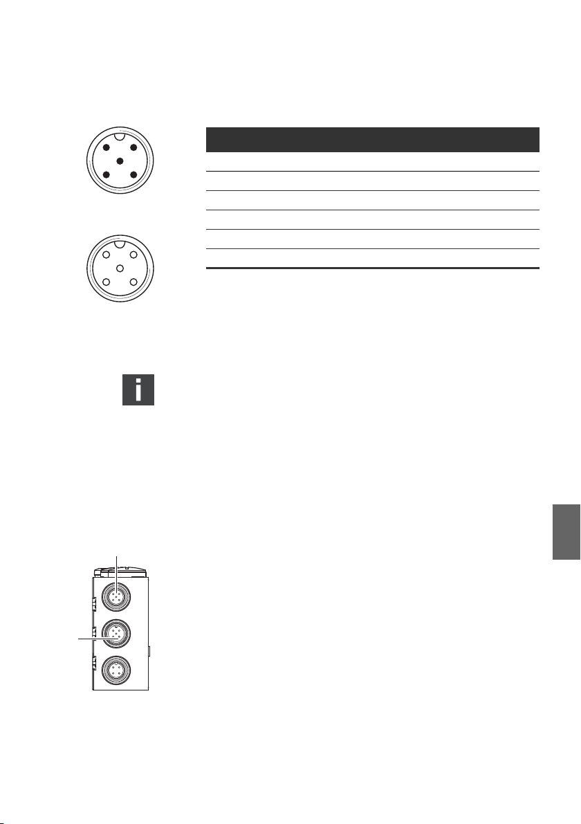
AVENTICS | DeviceNet | R412009416–BDL–001–AC 77
2
1
43
5
BUS IN
X71
2
3
4
1
5
X72
BUS OUT
Assembly
Table 5: Assignment X71 (BUS IN) and X72 (BUS OUT), M12,
A-coded DeviceNet
Pin Signal Meaning
1 Drain Shield via RC on FE (internally)
1) 2)
2V+
1) 2)
3V-
24 V bus supply
Ground / 0 V / GND bus supply
4 CAN_H CAN_H bus line (dominant high)
5 CAN_L CAN_L bus line (dominant low)
Housing Shield or functional grounding
1)
The bus coupler is supplied with power via X10. All lines are looped through.
The bus status of V+ and V- is checked internally.
2)
If V+ and V- have been incorrectly assigned, the LED will display a fault and the
device will stay in initialization status. Make sure that V+ and V- are assigned
on the bus plug.
The connection technology and plug assignment comply
with the ODVA technical directives.
When using a cable with a filler cord, this can be additionally
connected to pin 1 on the bus plug (X71/X72).
6.3.2 Connecting the bus coupler as an intermediate
station
1
the plug connections if you do not use pre-assembled
1. Set up the correct pin assignment (see Tab. 5 on page 77) on
English
cables.
X71
2
X72
X10
2. Connect the incoming bus connection to X71 (1).
3. Connect the outgoing bus cable with the next module using
the X72 output (2).
4. Connect the shield on both sides of the bus cable directly to
the plug housing (EMC housing) if non-pre-assembled
cables and plugs with metal housing are used. This protects
data lines from terminal interferences. Ensure that the plug
housing is securely fitted to the bus coupler housing.
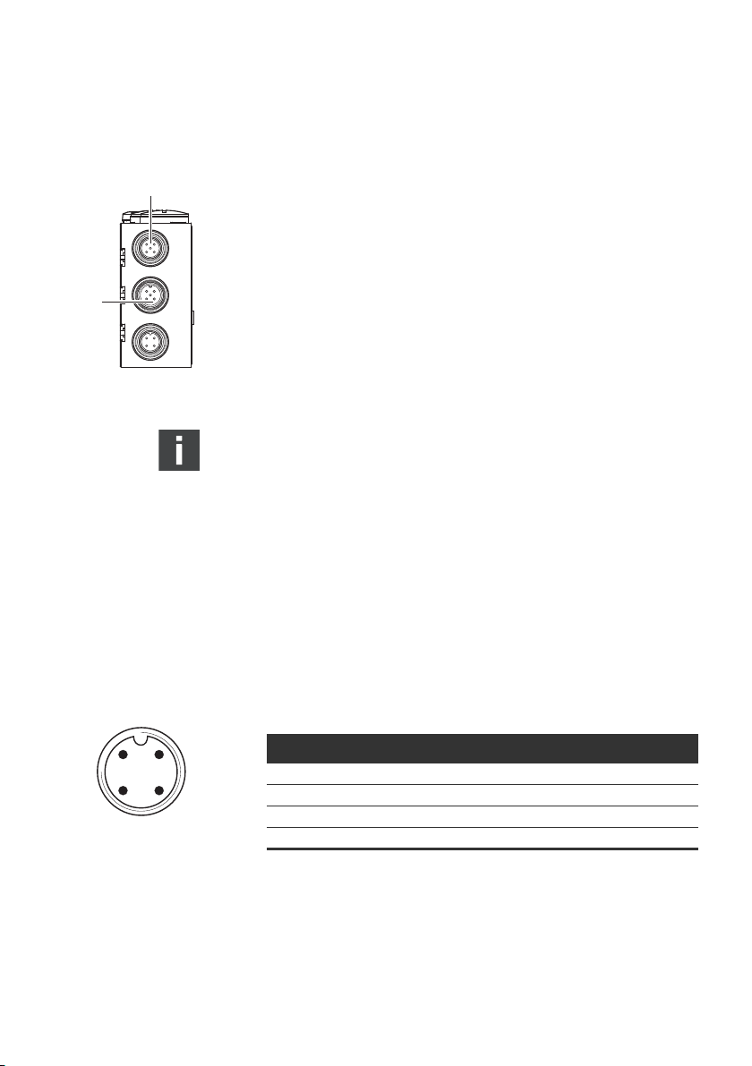
78 AVENTICS | DeviceNet | R412009416–BDL–001–AC
X71
X72
X10
1
2
2
1
43
POWER
X10
Assembly
6.3.3 Connecting the bus coupler as a final station
1.
Set up the correct pin assignment (see Tab. 5 on page 77) on
the plug connections if you do not use pre-assembled cables.
2. Connect the incoming bus connection to X71 (1).
3. Cover the X 72 (BUS OUT) socket with a DeviceNet end plug
(see chapter “Spare parts and accessories” on page 97).
4. Connect the shield on both sides of the bus cable directly to
the plug housing (EMC housing) if non-pre-assembled
cables and plugs with metal housing are used. This protects
data lines from terminal interferences. Ensure that the plug
housing is securely fitted to the bus coupler housing.
A potential equalization line of at least 10 mm2 is needed
between the devices to avoid compensating currents from
flowing over the shield of the bus coupler.
6.3.4 Connecting the bus coupler logic and load
supply
Power is supplied to the valves and the bus coupler via the X10
(POWER) plug.
When connecting the logic and load supply of the bus coupler,
ensure pin assignment according to Tab. 6.
Table 6: Assignment of the X10 (POWER) plug, M 12, A-coded
Pin X10 Assignment
1)
Both supply voltages (pin 2, pin 4) must be protected by an external fuse (3A, F).
DeviceNet
1U
2U
3OV Ground for UL, UQ1 and U
4UQ2Valve power supply1)
Bus coupler logic power supply
L
Valve power supply
Q1
1)
Q2
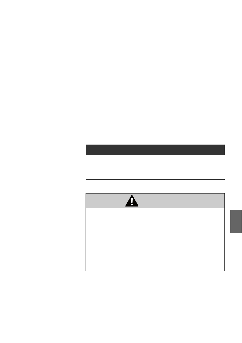
AVENTICS | DeviceNet | R412009416–BDL–001–AC 79
Assembly
W UL, UQ1 and UQ2 are galvanically connected to one another.
W With the U
and UQ2 valve supplies, the valves can be
Q1
switched off byte by byte (each byte represents 4 double or
8 single solenoid valves).
W The S4 sliding switches are used to assign the valve groups
(4 or 8 valves) (see "Selecting the valve supply" on page 84).
This enables e.g. a separate switch-off.
The power supply cable must fulfil the following requirements:
W Cable socket: 4-pin, A-coded without center hole
W Adjust the line cross-section to the total current and line
2
length: > 0.5 mm
per wire
W Length: Max. 20 m
Table 7: Power consumption on X10 (POWER) on bus coupler
Signal Assignment Tot al current
U
U
U
Logic Max. 0.5 A
L
Valves Max. 3 A
Q1
Valves Max. 3 A
Q2
CAUTION
Dangerous voltages
A power pack without safe isolation may lead to dangerous
voltages in the case of a fault. This may damage the system
and cause injuries arising from electric shock.
O Only use a power pack with safe isolation according to
EN 60747, VDE 0551 classification! This ensures that the
electric circuits comply with SELV/PELV electric circuits
in accordance with IEC 60364-4-41.
English
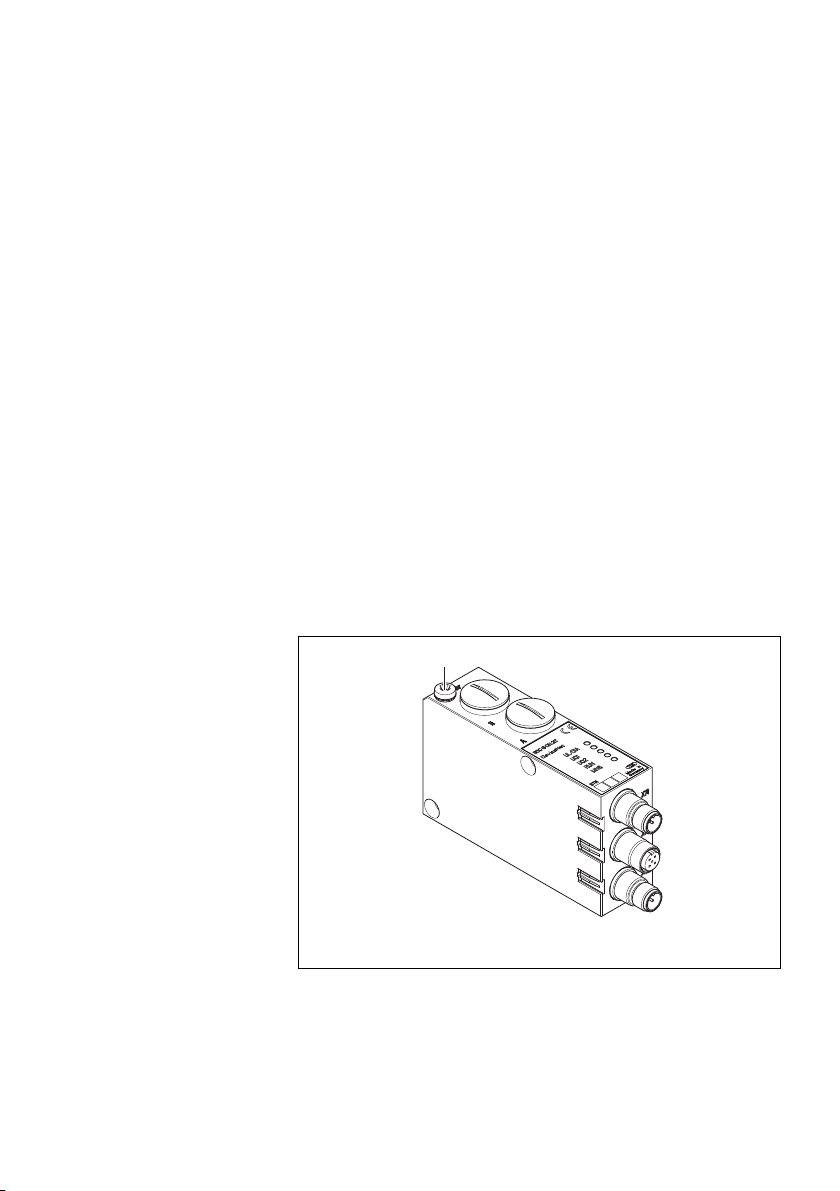
80 AVENTICS | DeviceNet | R412009416–BDL–001–AC
1
Assembly
To connect the bus coupler load supply:
1. Set up the correct pin assignment (see Tab. 6 on page 78) on
the plug connections if you do not use pre-assembled
cables.
2. Connect the bus coupler operating voltages using the plug
connector (see “Spare parts and accessories” on page 97).
3. Check the operating voltage specifications using the
electrical characteristics and comply with them (see chapter
“Technical Data” on page 96).
4. Provide power according to Tab. 7, page 79. Select the cable
cross-section according to the cable length and occurring
currents.
6.3.5 FE connection
Grounding on
the bus coupler
O To discharge EMC interferences, connect the FE connection
(1) on the bus coupler via a low-impedance line with the
functional earth.
2
Recommended cable cross-section: 10 mm
Fig. 5: FE connection on the bus coupler (1)
.

AVENTICS | DeviceNet | R412009416–BDL–001–AC 81
A
B
Commissioning and Operation
7 Commissioning and Operation
7.1 Making presettings
The following presettings have to be made:
W Setting the bus coupler address
W Selecting the valve supply
W Setting the baud rate
W Setting diagnostic messages
All of these settings are made using the switch beneath fittings
A and B.
Proceed as follows for all of the presettings:
1. Remove the corresponding fittings.
2. Adjust the corresponding setting as described below.
3.
Screw the fittings back in (0.6 + 0.2 Nm). Pay attention that the
sealing rings are positioned correctly.
7.1.1 Setting the baud rate
The baud rate is set at switch S3 (see Tab. 8 on page 82). It is
located under fitting A.
1. Open fitting A.
2. Set the baud rate (transfer rate) with the S3.1 to S3.3
switches in accordance with the information listed in Tab. 8
on page 82.
Default: 125 kBaud
English

82 AVENTICS | DeviceNet | R412009416–BDL–001–AC
0
9
8
7
6
5
4
3
2
1
0
9
8
7
6
5
4
3
2
1
S1
S2
S3
Commissioning and Operation
Table 8: S3, Switch assignments for baud rate setting
Baud rate Max. line length S3.3 S3.2 S3.1
Reserved ON ON ON
Reserved ON ON OFF
Reserved ON OFF ON
Reserved ON OFF OFF
Reserved OFF ON ON
500 kbit/s 100 m OFF ON OFF
250 kbit/s 250 m OFF OFF ON
1)
125 kbit/s
1)
Default settings
500 m OFF OFF OFF
7.1.2 Setting the bus coupler address
The station address is set using the S1 and S2 switches
(see Fig. 6).
Fig. 6:
S1, S2 address switches and S3 mode switch on the bus coupler
Both S1 and S2 rotary switches for the valve system station
address in the DeviceNet are located beneath fitting A.
O
Assign the station address freely from 0 to 63 with S1 and S2
(see Fig. 6) (the maximum MAC ID is 63):
– S1: Unit digits from 0 to 9
– S2: Tens digits from 0 to 9
– S1 + S2 = station address
Default: MAC ID = 63

AVENTICS | DeviceNet | R412009416–BDL–001–AC 83
Commissioning and Operation
7.1.3 Setting diagnostic messages
The S3 mode switch used to set the diagnostic messages is
located under the PG fitting A (see Fig. 6 on page 82).
The system is DeviceNet-conform on delivery. Diagnosis is
deactivated (S3.5 set to OFF).
O Activate or deactivate the diagnostic message to the master
with the S3.5 switch.
The modified switch position will only be activated after a
new “power on”.
This setting can also be assigned using the Module Control
Object. If assigned via the Module Control Object, the
position of S3.5 will become ineffective. Changes via the
Module Control Object only become effective after a STOP/
START.
The queued diagnoses are shown on the LEDs even if the
diagnostic message is turned off on the master.
Table 9: S3, defining the monitoring threshold for valve voltage
Bit Switch setting Function
3.1 OFF (default) / ON Baud rate (see Tab. 8 on page 82)
3.2 OFF (default)/ON Baud rate (see Tab. 8 on page 82)
3.3 OFF (default)/ON Baud rate (see Tab. 8 on page 82)
3.4 OFF (default)
ON
3.5 OFF (default)
ON
3.6 OFF (default)/ON NC
3.7 OFF (default)/ON NC
3.8 OFF (default)/ON NC
Threshold for U
Threshold for U
Diagnostic message deactivated
Diagnostic message activated
and UQ2 is 21.6V (10%)
Q1
and UQ2 is 20.4V (15%)
Q1
English
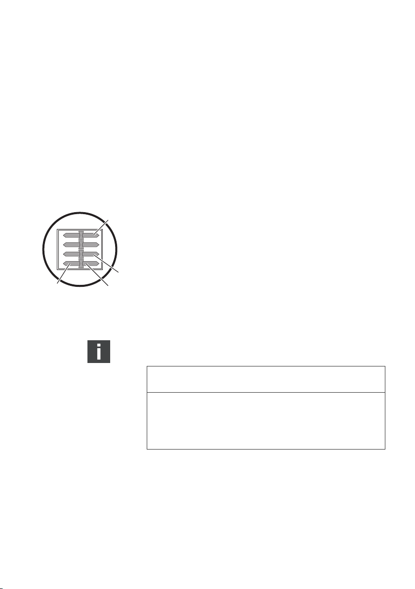
84 AVENTICS | DeviceNet | R412009416–BDL–001–AC
4321
DCBA
S4.4
S4.1
1*
2*
* Switch position
Commissioning and Operation
7.1.4 Switching the tolerance level for valve supply
U
and U
Q1
Q2
The threshold 20.4 V/21.6 V can be adjusted for different valve
series (see Tab. 9 on page 83). In the delivery condition, the
threshold is set to 21.6 V (10 %) (S 3.4 set to OFF). If the supply
voltage for the valve control drops below this threshold, a
diagnostic message will be generated.
7.1.5 Selecting the valve supply
The valve power supply can be selected block-wise with the S4
sliding switch (under fitting B). It is possible to switch between
and UQ2 voltages from the external X10 supply.
the U
Q1
When delivered, all switches are set to position 1.
NOTICE
Voltage at switches
Switches can be damaged if voltage is applied during
operation.
O Always operate switches in a voltage-free state!
O Always operate switches in a voltage-free state!

Table 10: Assignment of the S4 switches
Slider
plate
4.1 Power supply control
4.2 Power supply control
4.3 Power supply control
4.4 Power supply control
Function Switch position 1 Switch position 2
byte 1
byte 2
byte 3
byte 4
Voltage at switches
Switches can be damaged if voltage is applied during
operation.
O
How to assign the valve supply:
1.
Open screw cap B (see figure on page 81).
2. Using the S4 sliding switch, assign one of the two supply
voltages UQ1 or UQ2 to each valve group (see figure on
page 84 and 10).
AVENTICS | DeviceNet | R412009416–BDL–001–AC 85
Commissioning and Operation
(external supply,
U
Q1
PIN 2, white)
U
(external supply,
Q1
PIN 2, white)
U
(external supply,
Q1
PIN 2, white)
U
(external supply,
Q1
PIN 2, white)
UQ2 (external supply,
PIN 4, black)
U
(external supply,
Q2
PIN 4, black)
UQ2 (external supply,
PIN 4, black)
UQ2 (external supply,
PIN 4, black)
NOTICE
Always operate switches in a voltage-free state!
English

86 AVENTICS | DeviceNet | R412009416–BDL–001–AC
Commissioning and Operation
Examples for assignment of switch S4 and the supply of
assembled valves for 32 valve solenoids can be found in Tab. 11
and Tab. 12 on pages 87 and 88 (examples 1 to 3/examples 4
to 6, respectively). The following example combinations are
listed there:
Examples
Example 1 Subbases for double solenoid valves Double solenoid valves
Example 2 Subbases for double solenoid valves Single solenoid valves
Example 3 Subbases for double solenoid valves Single and double solenoid valves
Example 4 Subbases for single solenoid valves Single solenoid valves
Example 5 Subbases for double solenoid valves Double solenoid valves
Example 6 Subbases for double solenoid valves Single and double solenoid valves
1)
Other combinations may be selected in accordance with your requirements.
1)
Subbases used Valve equipment
combined with
Subbases for single solenoid valves Single solenoid valves
combined with
Subbases for single solenoid valves Single solenoid valves
From an electrical connection viewpoint, the subbases for
double solenoid valves must come first and then those for
single solenoid valves. The maximum number of solenoids
for all subbases is 32.
The assignment of switches and valve supplies changes if
module expansions are used (see operating instructions
R412008961). This also applies to the following examples in
Tab. 11 and Tab. 12).

AVENTICS | DeviceNet | R412009416–BDL–001–AC 87
Commissioning and Operation
Table 11: Examples for assignment of switches and valve supply, 32 valve coils
Example 1 Example 2 Example 3
Subbase for double solenoid valves
Address
Valve
position
1
2
3
4
5
6
7
8
9
10
11
12
Sol. LED
1)
14
14
14
14
14
14
14
14
14
14
14
14
Byte
Switches
S4.1 0 A0.0
A0.1 12 – 12
A0.2
A0.3 12 – 12
A0.4
A0.5 12 – 12
A0.6
A0.7 12 – 12
S4.2 1 A1.0
A1.1 12 – 12
A1.2
A1.3 12 – –
A1.4
A1.5 12 – –
A1.6
A1.7 12 – –
S4.3 2 A2.0
A2.1 12 –
A2.2
A2.3 12 – 12
A2.4
A2.5 12 – 12
A2.6
A2.7 12 – –
S4.4 3 A3.0 13 14
A3.1 12 – –
A3.2 14 14
A3.3 12 – 12
A3.4 15 14
A3.5 12 – 12
A3.6 16 14
A3.7 12 – –
1)
White fields indicate valve positions with double solenoid valves.
Fields highlighted in gray indicate valve positions with single solenoid valves.
Valve
position
1
2
3
4
5
6
7
8
9
10
11
12
13
14
15
16
Sol. LED
1)
14
14
14
14
14
14
14
14
14
14
14
14
14
14
14
14
Valve
position
1
2
3
4
5
6
7
8
9
10
11
12
13
14
15
16
Sol. LED
1)
14
14
14
14
14
14
14
14
14
14
14
English
14
14
14
14
14

88 AVENTICS | DeviceNet | R412009416–BDL–001–AC
Commissioning and Operation
Table 12: Examples for assignment of switches and valve supply, 32 valve coils
Example 4 Example 5 Example 6
Subbase for single
solenoid valves
Byte
Switches
S4.1 0 A0.0
A0.1
A0.2
A0.3
A0.4
A0.5
A0.6
A0.7
S4.2 1 A1.0
A1.1
A1.2
A1.3
A1.4
A1.5
A1.6
A1.7
S4.3 2 A2.0
A2.1
A2.2
A2.3
A2.4
A2.5
A2.6
A2.7
S4.4 3 A3.0
A3.1
A3.2
A3.3
A3.4
A3.5
A3.6
A3.7
1)
White fields indicate valve positions with double solenoid valves.
Fields highlighted in gray indicate valve positions with single solenoid valves.
Address
Valve
position
Sol. LED
1)
114
214 12 12
314
414 12 –
514
614 12 –
714
814 12 12
914514
10 14 614 12
11 14 714
12 14 814 12
13 14 914714
14 14 10 14 814
15 14 11 14 914
16 14 12 14 10 14
17 14 13 14 11 14
18 14 14 14 12 14
19 14 15 14 13 14
20 14 16 14 14 14
21 14 17 14 15 14
22 14 18 14 16 14
23 14 19 14 17 14
24 14 20 14 18 14
25 14 21 14 19 14
26 14 22 14 20 14
27 14 23 14 21 14
28 14 24 14 22 14
29 14 25 14 23 14
30 14 26 14 24 14
31 14 27 14 25 14
32 14 28 14 26 14
Subbase for single and double solenoid valves
Valve
position
1
2
3
4
Sol. LED
1)
14
14
14
14
Valve
position
1
2
3
4
5
6
Sol. LED
1)
14
14
14
14
14
14

AVENTICS | DeviceNet | R412009416–BDL–001–AC 89
Commissioning and Operation
7.2 Configuring the bus system
The configuration steps laid out in this section are superior to
the settings on the bus coupler which have already been
described (see "Making presettings" on page 81) and are a part
of the entire system's bus master configuration.
The work described here may only be carried out by qualified
electronics personnel and in compliance with the operator's
documentation on configuring the bus master, as well as
applicable technical standards, directives, and safety
regulations.
Before starting configuration, the following steps must have
been carried out and completed on the bus coupler:
W You have assembled the bus coupler and valve terminals
(see "Assembly" on page 74).
W
You have connected the bus coupler (see "Connecting the bus
coupler electrically" on page 75).
W You have carried out the presettings (see "Making
presettings" on page 81).
NOTICE
Configuration error
An incorrectly configured bus coupler will lead to malfunctions
in the system and may damage the system.
O The configuration may only be carried out by qualified
electronics personnel!
O Configure the bus system in accordance with your system
requirements, the manufacturer’s specifications, and all
valid technical standards, directives, and safety regulations.
Take the operator’s documentation on configuring the bus
master into account.
The operating behavior, relevant objects and parameters to
configure the bus coupler, possible setting examples, and scope
of function are listed in the chapter "Appendix Information on
the bus master configuration with DeviceNet" from page 98.
English
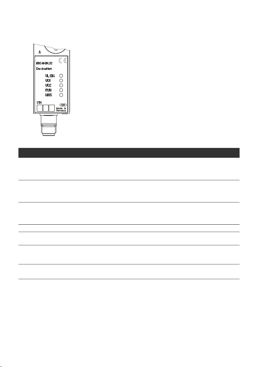
90 AVENTICS | DeviceNet | R412009416–BDL–001–AC
Commissioning and Operation
7.3 Testing and diagnosis on the modules
7.3.1 Reading the diagnostic display on the bus
coupler
The LEDs on the front panel of the bus coupler show the
messages from Tab. 13.
O Before commissioning and during operation, regularly
check bus coupler functions by reading the diagnostic
displays.
Table 13: Definitions for diagnostic LEDs on the bus coupler
LED Signal Description
/DIA Green Logic supply available
U
L
Red Sensor supply overload (group diagnosis)
Off No logic supply available
U
Q1
U
Q2
Green Valve supply UQ1 OK
Red Low voltage (12 V < U
Off Valve supply U
< 12 V
Q1
Green Valve supply UQ2 OK
Red Low voltage (12 V < U
Off Valve supply U
< 12 V
Q2
< 21.6 V/20.4 V (S3.4))
Q1
< 21.6 V/20.4 V (S3.4))
Q2
RUN Green Initialization completed (operative status).
RUN
+UL
RUN
+MNS
UL
RUN Flashes green
+MNS off
Green
Off
Flashes red
Flashes green
Initialization after power on
Bus power supply (V+/V-) missing, device remains in initialization
2)
status
4)
3)
Inadmissible Mac ID ( >63) or duplicate Mac ID error
MNS Red
1) This display appears only as long as the overloaded output is controlled or as long as the total current of the sensor
supply is exceeded.
2) Flashing frequency 1 0.5 s on/0.5 s off
3) Flashing frequency 2 0.125 s on/0.125 s off
4) Flashing frequency 3 0.8 s on/0.2 s off
1)

AVENTICS | DeviceNet | R412009416–BDL–001–AC 91
Commissioning and Operation
The function of the MNS LED corresponds to the ODVA
specification (see Spec.: "The CIP NETWORKS LIBRARY Volume
Three: DeviceNet
Adaptation of CIP Edition 1.5, November 2007")
7.4 Commissioning the VS with bus coupler
Before commissioning the system, the following steps must
have been carried out and completed:
W You have assembled the valve terminal and the bus coupler
(see “Assembling the valve system with the bus coupler” on
page 74).
W You have connected the bus coupler (see “Connecting the
bus coupler electrically” on page 75).
W You have made the settings and configured the system (see
“Making presettings” on page 81).
W You have configured the bus master so that it actuates the
valves correctly.
Commissioning and operation may only be carried out by
qualified electrical or pneumatic personnel or an instructed
person under the direction and supervision of qualified
personnel (see “Personnel qualifications” on page 67).
English

92 AVENTICS | DeviceNet | R412009416–BDL–001–AC
Commissioning and Operation
CAUTION
Uncontrolled actuator movements when the pneumatics are
switched on
Danger of injury if the system is in an undefined state and the
manual overrides are set to position “1”.
O Put the system in a defined state before switching it on.
O Set all manual overrides to position "0".
O Make sure that no personnel are within the hazardous
zone when the compressed air supply is switched on.
O Also observe the applicable instructions and safety
information in the VS operating instructions.
1. Switch on the operating voltage.
2. Check the LED displays on all modules.
3. Switch on the compressed air supply.
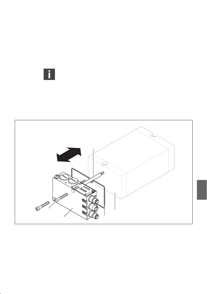
AVENTICS | DeviceNet | R412009416–BDL–001–AC 93
Disassembly and Exchange
8 Disassembly and Exchange
You can exchange the bus coupler, if needed.
The AVENTICS warranty only applies to the delivered
configuration and extensions taken into account in the
configuration. The warranty no longer applies after a
conversion that exceeds these extensions.
8.1 Exchanging the bus coupler
4
1
2
Fig. 7: Exchanging the bus coupler on a VS
1 M5x35 hexagon socket head screws, 3 + 0.5 Nm 4 Tie rod
2 Bus coupler 5 VS EP end plate
3 Seal
5
3
English

94 AVENTICS | DeviceNet | R412009416–BDL–001–AC
Disassembly and Exchange
CAUTION
Applied voltage and high pressure!
Danger of injury from electric shocks and sudden pressure
drops.
O Make sure that the system is not under voltage or
pressure.
O Observe the stipulated precautionary measures when
working with ESD-sensitive assemblies.
To exchange the module:
1.
Disconnect the electrical connections from the bus coupler
4
).
(
2. Loosen the bus coupler (2) (2 hexagon socket head screws
DIN 912 – M4 (1), wrench size 3).
3. Remove the bus coupler (2) from the EP end plate (4).
4. Push the new bus coupler (4) onto the EP end plate (4).
5. Make sure that the seal (3) is fitted correctly.
6. Screw down the bus coupler (2) (2 hexagon socket head
screws DIN 912 – M4 (1) each, wrench size 3). Tightening
torque 3.0 + 0.5 Nm.
7. Make all the presettings on the new bus coupler (4)
(see “Making presettings” on page 81).
8. Reestablish the connections.
9. Check the configuration and adjust it if necessary
(see “Configuring the bus system” on page 89).
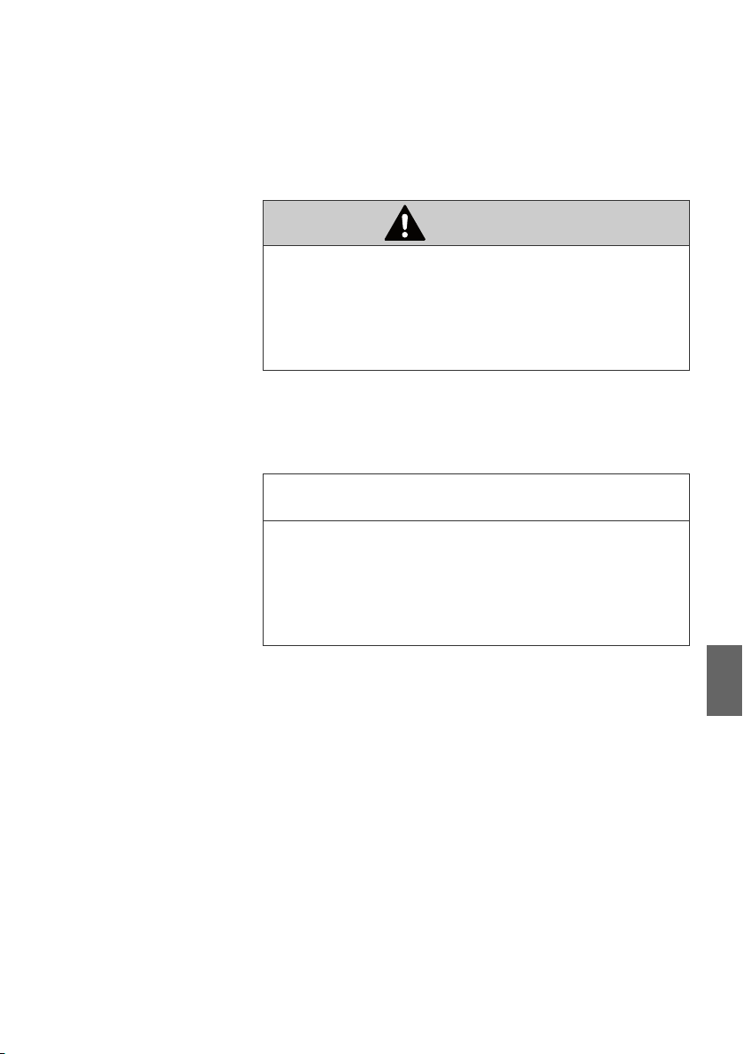
AVENTICS | DeviceNet | R412009416–BDL–001–AC 95
Care and Maintenance
9 Care and Maintenance
CAUTION
Applied voltage and high pressure!
Danger of injury from electric shocks and sudden pressure
drops.
O Make sure the system is not under pressure or voltage
before carrying out any service or maintenance work.
9.1 Servicing the modules
NOTICE
Damage to the housing surface caused by solvents and
aggressive detergents!
The surfaces and seals could be damaged by aggressive
solvents and cleaning agents.
O Never use solvents or strong detergents!
O Regularly clean the device with a damp cloth. Use only water
or a mild detergent.
9.2 Maintaining the modules
The bus couplers of the VS are maintenance-free.
O Comply with the maintenance intervals and specifications
for the entire system.
English

96 AVENTICS | DeviceNet | R412009416–BDL–001–AC
Technical Data
10 Technical Data
10.1 Characteristics
General
Protection class according to
EN 60 529/IEC 529 IP65 when assembled
Ambient temperature
W Operation
W Storage
Electromagnetic compatibility
Interference immunity EN 61000-6-2
Interference emission EN 61000-6-4
U
0 °C to +50 °C, without condensation
–20 °C to +70 °C
10.2 Bus coupler
Electrics
Operating voltage
W Logic
–U
L
–I
L
–Fuse protection for logic voltage 500 mAF
W Load U
–Fuse protection for the power supply 2x 3.0 AF
Cable length for power supply Max. 20 m
Maximum current in the 0 V line 4 A
Internal voltage drop 0.6 V
Max. output current per valve output 100 mA
Number of outputs Max. 32
Number of output bytes Fixed 4 byte output and 0 byte input
Run-up time Approx. 1 s
, U
Q1
Q2
according to IEC 60364-4-41, residual ripple 0.5 %
Protective extra-low voltage (SELV/PELV)
24 V DC (+20 %/–15 %)
50 mA
24 V DC (10 %/15 %)

AVENTICS | DeviceNet | R412009416–BDL–001–AC 97
Spare parts and accessories
11 Spare parts and accessories
11.1 Bus coupler
Order number
VS bus coupler for DeviceNet with control for 32 valve solenoids
Accessories
Set: Seal, 2 screws M5, 1 screw FE R412008885
10x metric blanking screws R412008886
5x slide-in card labels R412008887
DeviceNet end plug 8941054264
DeviceNet data plug Data input plug,
M12x1 protective cap 1823312001
1)
Delivery incl. 2 hexagonal socket-head screws, seal and manual
M12x1 socket, 5-pin straight,
A-coded, cable Ø 6–8 mm
Data output plug,
M12x1 pin, 5-pin straight,
A-coded, cable Ø 6–8 mm
1)
R412008539
8942051602
8942051612
11.2 Power plug for bus couplers
Plug connector for power supply,
M12x1 coupling, 4-pin for cable Ø 4–8 mm,
A-coded
12 Disposal
Dispose of the device in accordance with the currently
applicable regulations in your country.
English
Order number
180° (X10, POWER) 8941054324
90° (X10, POWER) 8941054424

98 AVENTICS | DeviceNet | R412009416–BDL–001–AC
Appendix Information on the bus master configuration with DeviceNet
13 Appendix
Information on the bus master
configuration with DeviceNet
13.1 Electronic Data Sheet (EDS)
The EDS Electronic Data Sheet is an ASCII file specified by ODVA
that describes the objects/performance data of the DeviceNet.
This file exists for the bus coupler and is called BDC-B-DN_32.EDS.
The EDS file can be downloaded from the Internet:
www.aventics.com/mediadirectory
13.2 Operating behavior
The behavior of the bus connection depends on the CAN and
DeviceNet characteristics as well as the I/O configuration.
As a "Group 2 Only Server", the bus coupler supports the
"Predefined Master Slave Connection Set" according to "The CIP
Networks Library Volume 3, DeviceNet Adaptation of CIP,
Edition 1.5".
13.2.1 Start-up behavior
Behavior after power on After the assembly has been switched on (connecting the 24 V
logics supply), the hardware components are tested.
If the start-up test has been successfully completed and bus
voltage is available, the bus coupler is initialized according to
the presettings on the rotary and DIP switches.
A “Duplicate MAC ID Check” in accordance with the DeviceNet
specification is carried out at the end of the initialization stage
to check if there is a second participant with the same MAC ID
on the bus.
The participant can then be initialized by a DeviceNet master.

AVENTICS | DeviceNet | R412009416–BDL–001–AC 99
Appendix Information on the bus master configuration with DeviceNet
13.3 DeviceNet Objects
13.3.1 Identity object (Class 0x01)
Table 14: Class and instance attributes – identity object
Object
class
0x01 0x00 0x01 Revision of the identity object
0x01 0x01 0x01 Vendor ID
Object
instance
Object
attribute
0x02 Product type
0x03 Product code
0x04 Revision
0x05 Status
0x06 Serial Number
0x07 Product name
Object description
0x11F (hex)
AVENTICS GmbH
0x07 (hex) general purpose
discrete I/O
0x1F (hex)
of the bus coupler BCD-B-DN_32
Summed device status
(bit coding in accordance with the
DeviceNet specifications)
Clear serial number in conjunction
with the vendor ID
BDC-B-DN_32 DeviceNet Slave
English
Table 15: Common services – identity object
Service code Service name
0x05 Reset (see below)
0x0E Get attribute single
The class 0x01, instance 0x01, attribute 0x00 for reset
service resets the device. All communication connections
are terminated. The settings on the rotary and DIP switches
(MAC ID, baud rate, diagnosis) are read in again and the
assembly is re-initialized.

100 AVENTICS | DeviceNet | R412009416–BDL–001–AC
Appendix Information on the bus master configuration with DeviceNet
13.3.2 Message router object (class 0x02)
– Class and instance attributes:
No attributes are supported for this object.
– Common services:
No services are supported for this object.
13.3.3 DeviceNet Object (Class 0x03)
Table 16: Class and instance attributes – DeviceNet object
Object
class
0x03 0x00 0x01 Revision
0x03 0x01 0x01 MAC ID
Object
instance
Object
attribute
0x02 Baud rate
0x03 BOI
0x04 Bus off counter
0x05 Allocation information
0x06 MAC ID switch changed
Object description
of the DeviceNet object
of the addressed participant
Identification of the set baud rate:
0x00 125 kbit/s
0x01 250 kbit/s
0x02 500 kbit/s
Handling of the bus off interrupt:
0x00 CAN controller goes into the
bus off/reset state and remains
there (default).
0x01 CAN controller is reset and
tries to restart communication.
Number of bus off events
Information on the active
connections of the predefined
master/slave connection set
0x00: Not changed since switch
on/reset
0x01: Changed since switch on/
reset
 Loading...