

AVENTICS BDC Module, B-Design, with EtherCAT, Operating instructions, Instrucciones de servicio: Módulo BDC, Diseño B, con EtherCAT, Istruzioni per l'uso: Modulo BDC, B-Design, con EtherCAT, Betriebsanleitung: BDC-Modul, B-Design, mit EtherCAT, Mode d’emploi: Module BDC, B-Design, avec EtherCAT Manuals & Guides [es]
...
Betriebsanleitung | Operating instructions | Mode d’emploi |
Istruzioni per l'uso | Instrucciones de servicio | Bruksanvisning
Buskoppler für BDC, B-Design
Bus coupler for BDC, B-Design
Coupleur de bus pour BDC, design B
Accoppiatore bus per BDC, design B
Acoplador de bus para BDC, diseño B
Fältbussnod för BDC, B-Design
EtherCAT
R412012792/07.2014,
Replaces: 10.2009, DE/EN/FR/IT/ES/SV
DeutschEnglishFrançaisItalianoEspañolSvenska


AVENTICS | EtherCAT | R412012792–BDL–001–AB 3
Inhalt
Inhalt
1 Zu dieser Dokumentation ............................... 5
1.1 Gültigkeit der Dokumentation...............................5
1.2 Erforderliche und ergänzende
Dokumentationen .....................................................5
1.3 Darstellung von Informationen ............................ 5
1.3.1 Sicherheitshinweise .............................................. 6
1.3.2 Symbole ..................................................................... 6
1.3.3 Abkürzungen ............................................................ 7
2 Sicherheitshinweise ....................................... 8
2.1 Zu diesem Kapitel.....................................................8
2.2 Bestimmungsgemäße Verwendung ................... 8
2.3 Nicht bestimmungsgemäße Verwendung ........8
2.4 Qualifikation des Personals................................... 9
2.5 Allgemeine Sicherheitshinweise .......................10
2.6 Produkt- und technologieabhängige
Sicherheitshinweise ..............................................11
3 Einsatzbereiche ............................................. 12
4 Lieferumfang ................................................. 13
5 Gerätebeschreibung ..................................... 13
5.1 Gesamtübersicht Ventilsystem..........................14
5.2 Gerätekomponenten..............................................15
5.2.1 Buskoppler ............................................................. 15
6 Montage .......................................................... 16
6.1 Buskoppler am VS montieren.............................16
6.1.1 Abmessungen ........................................................ 17
6.2 Module beschriften ................................................18
6.3 Buskoppler elektrisch anschließen...................19
6.3.1 Allgemeine Hinweise zum Anschluss des
Buskopplers ........................................................... 20
6.3.2 Buskoppler als Zwischenstation
anschließen ............................................................ 21
6.3.3 Buskoppler als letzte Station anschließen ... 21
6.3.4 Logik- und Lastversorgung des Buskopplers
anschließen ............................................................ 22
6.3.5 FE-Anschluss ......................................................... 24
Deutsch

4 AVENTICS | EtherCAT | R412012792–BDL–001–AB
Inhalt
7 Inbetriebnahme und Bedienung .................. 25
7.1 Voreinstellungen vornehmen.............................. 25
7.1.1 Diagnosemeldungen einstellen ........................ 25
7.1.2 Umschalten der Toleranzpegel der
Ventilversorgung U
7.1.3 Ventilversorgung auswählen ............................ 27
7.2 Buskoppler konfigurieren .................................... 32
7.3 Test und Diagnose am Buskoppler ...................33
7.3.1 Diagnoseanzeige am Buskoppler ablesen .... 33
7.4 Buskoppler in Betrieb nehmen........................... 35
8 Demontage und Austausch .......................... 36
8.1 Buskoppler austauschen......................................36
9 Pflege und Wartung ...................................... 38
9.1 Module pflegen........................................................38
9.2 Buskoppler warten.................................................38
10 Technische Daten .......................................... 39
10.1 Kenngrößen..............................................................39
10.2 Buskoppler................................................................39
11 Ersatzteile und Zubehör ............................... 40
11.1 Buskoppler................................................................40
11.2 Power-Stecker für Buskoppler........................... 40
12 Entsorgung .................................................... 40
13 Anhang ........................................................... 41
13.1 Angaben zur Busmasterkonfiguration
mit EtherCAT............................................................41
13.2 Betriebsverhalten...................................................41
13.3 Anlaufverhalten.......................................................41
13.4 Konfigurationsdatei................................................42
14 Stichwortverzeichnis .................................... 43
Q1
und U
.......................... 27
Q2

AVENTICS | EtherCAT | R412012792–BDL–001–AB 5
Zu dieser Dokumentation
1 Zu dieser Dokumentation
1.1 Gültigkeit der Dokumentation
Diese Dokumentation enthält wichtige Informationen, um
das Produkt sicher und sachgerecht zu montieren, zu
bedienen, zu warten und einfache Störungen selbst zu
beseitigen.
O Lesen Sie diese Dokumentation vollständig und
insbesondere das Kapitel „Sicherheitshinweise“,
bevor Sie mit dem Produkt arbeiten.
1.2 Erforderliche und ergänzende
Dokumentationen
O Nehmen Sie das Produkt erst in Betrieb, wenn Ihnen
folgende Dokumentationen vorliegen und Sie diese
verstanden und beachtet haben.
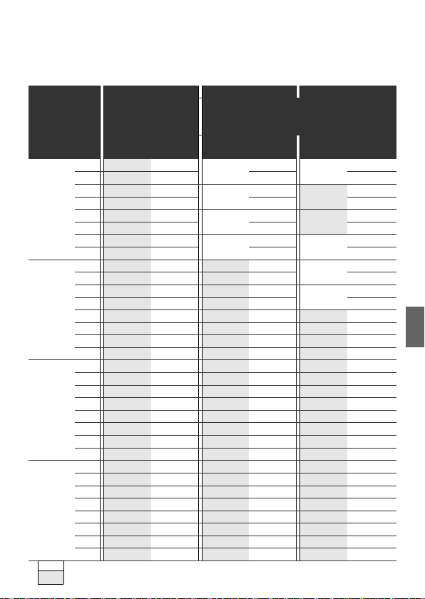
Tabelle 1: Erforderliche und ergänzende Dokumentationen
Titel Dokumentnummer Dokumentart
Dokumentation des Ventilsystems
HF03 LG
Dokumentation des Ventilsystems
HF04 D-SUB
Anlagendokumentation
R412008233 Anleitung
R412015493 Anleitung
Weitere Angaben zu Komponenten entnehmen Sie dem
Online- Katalog unter
www.aventics.com/pneumatics-catalog.
1.3 Darstellung von Informationen
Damit Sie mit dieser Dokumentation schnell und sicher
mit Ihrem Produkt arbeiten können, werden einheitliche
Sicherheitshinweise, Symbole, Begriffe und Abkürzungen
verwendet. Zum besseren Verständnis sind diese in den
folgenden Abschnitten erklärt.
Deutsch

6 AVENTICS | EtherCAT | R412012792–BDL–001–AB
Zu dieser Dokumentation
1.3.1 Sicherheitshinweise
In dieser Dokumentation stehen Sicherheitshinweise vor
einer Handlungsabfolge, bei der die Gefahr von
Personen- oder Sachschäden besteht. Die beschriebenen
Maßnahmen zur Gefahrenabwehr müssen eingehalten
werden.
Sicherheitshinweise sind wie folgt aufgebaut:
SIGNALWORT
Art und Quelle der Gefahr
Folgen bei Nichtbeachtung
O Maßnahme zur Gefahrenabwehr
W Warnzeichen: macht auf die Gefahr aufmerksam
W Signalwort: gibt die Schwere der Gefahr an
W Art und Quelle der Gefahr: benennt die Art und Quelle
der Gefahr
W Folgen: beschreibt die Folgen bei Nichtbeachtung
W Abwehr: gibt an, wie man die Gefahr umgehen kann
Tabelle 2: Gefahrenklassen nach ANSI Z535.6-2006
Warnzeichen, Signalwort Bedeutung
Kennzeichnet eine gefährliche Situation, in der
VORSICHT
ACHTUNG
leichte bis mittelschwere Körperverletzungen
eintreten können, wenn sie nicht vermieden wird
Sachschäden: Das Produkt oder die Umgebung
können beschädigt werden.
1.3.2 Symbole
Die folgenden Symbole kennzeichnen Hinweise, die nicht
sicherheitsrelevant sind, jedoch die Verständlichkeit der
Dokumentation erhöhen.
AVENTICS | EtherCAT | R412012792–BDL–001–AB 7
Tabelle 3: Bedeutung der Symbole
Symbol Bedeutung
Wenn diese Information nicht beachtet
wird, kann das Produkt nicht optimal
genutzt bzw. betrieben werden.
O einzelner, unabhängiger Handlungsschritt
1.
2.
3.
nummerierte Handlungsanweisung:
Die Ziffern geben an, dass die
Handlungsschritte aufeinander folgen.
Zu dieser Dokumentation
1.3.3 Abkürzungen
In dieser Dokumentation werden folgende Abkürzungen
verwendet:
Tabelle 4: Abkürzungen
Bezeichnung Bedeutung
BTN Busteilnehmer-Nummer
CAT5e Übertragungskabel mit der (Kategorie 5e)
FE Funktionserde
EMV Elektromagnetische Verträglichkeit
EP-Endplatte Endplatte mit elektrischen und pneumatischen Anschlüssen
ESD Electro Static Discharge (Elektrostatische Entladung)
ETG EtherCAT Technology Group
GPI General Purpose Input
GPIO General Purpose Input Output
GPO General Purpose Output
INIT Mode Initialisierungsmodus
P-Endplatte Endplatte mit pneumatischen Anschlüssen
SELV/PELV Kleinschutzspannung
S/STP Screened/Shielded Twisted Pair
UDP/IP User Datagram Protocol/Internet Protocol
VS Ventilsystem
Deutsch

8 AVENTICS | EtherCAT | R412012792–BDL–001–AB
Sicherheitshinweise
2 Sicherheitshinweise
2.1 Zu diesem Kapitel
Das Produkt wurde gemäß den allgemein anerkannten
Regeln der Technik hergestellt. Trotzdem besteht die
Gefahr von Personen- und Sachschäden, wenn Sie dieses
Kapitel und die Sicherheitshinweise in dieser
Dokumentation nicht beachten.
O Lesen Sie diese Dokumentation gründlich und
vollständig, bevor Sie mit dem Produkt arbeiten.
O Bewahren Sie die Dokumentation so auf, dass sie
jederzeit für alle Benutzer zugänglich ist.
O Geben Sie das Produkt an Dritte stets zusammen mit
den erforderlichen Dokumentationen weiter.
2.2 Bestimmungsgemäße
Ver wend ung
Bei dem Produkt handelt es sich um eine
elektropneumatische Anlagenkomponente.
Sie dürfen das Produkt wie folgt einsetzen:
W ausschließlich im industriellen Bereich.
W unter Einhaltung der in den technischen Daten
genannten Leistungsgrenzen.
Das Produkt ist für den professionellen Gebrauch und
nicht für die private Verwendung bestimmt.
Die bestimmungsgemäße Verwendung schließt auch ein,
dass Sie diese Dokumentation und insbesondere das
Kapitel „Sicherheitshinweise“ vollständig gelesen und
verstanden haben.
2.3 Nicht bestimmungsgemäße
Ver wend ung
Jeder andere Gebrauch als in der bestimmungsgemäßen
Verwendung beschrieben ist nicht bestimmungsgemäß
und deshalb unzulässig.
Wenn ungeeignete Produkte in sicherheitsrelevanten
Anwendungen eingebaut oder verwendet werden,
können unbeabsichtigte Betriebszustände in der
Anwendung auftreten, die Personen- und/oder
Sachschäden verursachen können. Setzen Sie daher ein

AVENTICS | EtherCAT | R412012792–BDL–001–AB 9
Sicherheitshinweise
Produkt nur dann in sicherheitsrelevanten Anwendungen
ein, wenn diese Verwendung ausdrücklich in der
Dokumentation des Produkts spezifiziert und erlaubt ist.
Beispielsweise in Ex-Schutz Bereichen oder in
sicherheitsbezogenen Teilen einer Steuerung
(funktionale Sicherheit).
Für Schäden bei nicht bestimmungsgemäßer
Verwendung übernimmt die AVENTICS GmbH keine
Haftung. Die Risiken bei nicht bestimmungsgemäßer
Verwendung liegen allein beim Benutzer.
Zur nicht bestimmungsgemäßen Verwendung des
Produkts gehört:
W die Verwendung außerhalb der Anwendungsgebiete,
die in dieser Anleitung genannt werden,
W die Verwendung unter Betriebsbedingungen, die von
den in dieser Anleitung beschriebenen abweichen.
2.4 Qualifikation des Personals
Die in dieser Dokumentation beschriebenen Tätigkeiten
erfordern grundlegende Kenntnisse der Elektrik und
Pneumatik sowie Kenntnisse der zugehörigen
Fachbegriffe. Um die sichere Verwendung zu
gewährleisten, dürfen diese Tätigkeiten daher nur von
einer entsprechenden Fachkraft oder einer
unterwiesenen Person unter Leitung einer Fachkraft
durchgeführt werden.
Eine Fachkraft ist, wer aufgrund seiner fachlichen
Ausbildung, seiner Kenntnisse und Erfahrungen sowie
seiner Kenntnisse der einschlägigen Bestimmungen die
ihm übertragenen Arbeiten beurteilen, mögliche
Gefahren erkennen und geeignete
Sicherheitsmaßnahmen treffen kann. Eine Fachkraft
muss die einschlägigen fachspezifischen Regeln
einhalten.
Deutsch

10 AVENTICS | EtherCAT | R412012792–BDL–001–AB
Sicherheitshinweise
2.5 Allgemeine Sicherheitshinweise
W Beachten Sie die gültigen Vorschriften zur
Unfallverhütung und zum Umweltschutz.
W Beachten Sie die Sicherheitsvorschriften und -
bestimmungen des Landes, in dem das Produkt
eingesetzt/angewendet wird.
W Verwenden Sie AVENTICS-Produkte nur in technisch
einwandfreiem Zustand.
W Beachten Sie alle Hinweise auf dem Produkt.
W Personen, die AVENTICS-Produkte montieren,
bedienen, demontieren oder warten dürfen nicht
unter dem Einfluss von Alkohol, sonstigen Drogen
oder Medikamenten, die die Reaktionsfähigkeit
beeinflussen, stehen.
W Verwenden Sie nur vom Hersteller zugelassene
Zubehör- und Ersatzteile, um Personengefährdungen
wegen nicht geeigneter Ersatzteile auszuschließen.
W Halten Sie die in der Produktdokumentation
angegebenen technischen Daten und
Umgebungsbedingungen ein.
W Wenn in sicherheitsrelevanten Anwendungen
ungeeignete Produkte eingebaut oder verwendet
werden, können unbeabsichtigte Betriebszustände in
der Anwendung auftreten, die Personen- und/oder
Sachschäden verursachen können. Setzen Sie daher
ein Produkt nur dann in sicherheitsrelevante
Anwendungen ein, wenn diese Verwendung
ausdrücklich in der Dokumentation des Produkts
spezifiziert und erlaubt ist.
W Sie dürfen das Produkt erst dann in Betrieb nehmen,
wenn festgestellt wurde, dass das Endprodukt
(beispielsweise eine Maschine oder Anlage), in das
die AVENTICS-Produkte eingebaut sind, den
länderspezifischen Bestimmungen,
Sicherheitsvorschriften und Normen der Anwendung
entspricht.

AVENTICS | EtherCAT | R412012792–BDL–001–AB 11
Sicherheitshinweise
2.6 Produkt- und
technologieabhängige
Sicherheitshinweise
W Sie dürfen das Gerät grundsätzlich nicht verändern
oder umbauen.
W Verwenden Sie das Gerät ausschließlich im
Leistungsbereich, der in den technischen Daten
angegeben ist.
W
Belasten Sie das Gerät unter keinen Umständen
mechanisch. Stellen Sie keine Gegenstände darauf ab.
W Sie dürfen dieses Gerät nur im industriellen Bereich
einsetzen (Klasse A). Für den Einsatz im Wohnbereich
(Wohn-, Geschäfts- und Gewerbebereich) ist eine
Einzelgenehmigung bei einer Behörde oder Prüfstelle
einzuholen. In Deutschland werden solche
Einzelgenehmigungen von der Regulierungsbehörde
für Telekommunikation und Post (RegTP) erteilt.
W
Stellen Sie sicher, dass die Spannungsversorgung
innerhalb der angegebenen Toleranz der Module liegt.
W Beachten Sie die Sicherheitshinweise der
Betriebsanleitung Ihres Ventilsystems.
W Alle Komponenten werden aus einem 24-V-Netzteil
versorgt. Das Netzteil muss mit einer sicheren
Trennung nach EN 60742, Klassifikation VDE 0551
ausgerüstet sein. Damit gelten die entsprechenden
Stromkreise als SELV/PELV-Stromkreise nach
IEC 60364-4-41.
W Schalten Sie die Betriebsspannung aus, bevor Sie
Bei der Montage W Schalten Sie immer den betreffenden Anlagenteil
Stecker verbinden oder trennen.
spannungsfrei und drucklos, bevor Sie das Gerät
montieren oder demontieren. Sorgen Sie dafür, dass
die Anlage während der Montagearbeiten gegen
Wiederanschalten gesichert ist.
W Erden Sie die Module und das Ventilsystem. Beachten
Sie die folgenden Normen bei der Installation des
Systems:
– DIN EN 50178, Klassifikation VDE 0160
– VDE 0100
Deutsch

12 AVENTICS | EtherCAT | R412012792–BDL–001–AB
Einsatzbereiche
W
Bei der
Inbetriebnahme
Während des Betriebs W Sorgen Sie für genügend Luftaustausch bzw. für
Bei der Reinigung W Verwenden Sie niemals Lösemittel oder aggressive
Die Installation darf nur in spannungsfreiem und
drucklosem Zustand und nur durch geschultes
Fachpersonal erfolgen. Führen Sie die elektrische
Inbetriebnahme nur in drucklosem Zustand durch, um
gefährliche Bewegungen der Aktoren zu vermeiden.
W Nehmen Sie das System nur in Betrieb, wenn es
komplett montiert, korrekt verdrahtet und
konfiguriert ist und nachdem Sie es getestet haben.
W Das Gerät unterliegt der Schutzklasse IP65. Stellen
Sie vor der Inbetriebnahme sicher, dass alle
Dichtungen und Verschlüsse der
Steckerverbindungen dicht sind, um zu verhindern,
dass Flüssigkeiten und Fremdkörper in das Gerät
eindringen können.
ausreichend Kühlung, wenn Ihr Ventilsystem
Folgendes aufweist:
–volle Bestückung
– Dauerbelastung der Magnetspulen
Reinigungsmittel. Reinigen Sie das Gerät
ausschließlich mit einem leicht feuchten Tuch.
Verwenden Sie dazu ausschließlich Wasser und ggf.
ein mildes Reinigungsmittel.
3 Einsatzbereiche
Der Buskoppler dient zur elektrischen Ansteuerung der
Ventile über die Echtzeit-Ethernet-Technologie EtherCAT.
Der Buskoppler ist ausschließlich für den Betrieb als
Slave an einem EtherCAT-Strang nach IEC 61158/61784
bestimmt.

AVENTICS | EtherCAT | R412012792–BDL–001–AB 13
Lieferumfang
4 Lieferumfang
Im Lieferumfang eines konfigurierten Ventilsystems sind
enthalten:
W 1 Ventilsystem gemäß Konfiguration und Bestellung
W 1 Betriebsanleitung zum Ventilsystem
W 1 Betriebsanleitung zum Buskoppler
Im Lieferumfang eines Buskoppler-Teilesatzes sind
enthalten:
W 1 Buskoppler mit Dichtung und
2 Befestigungsschrauben
W 1 Betriebsanleitung zum Buskoppler
Das VS wird individuell konfiguriert. Die genaue
Konfiguration können Sie sich mit Ihrer
Bestellnummer im Internet-Konfigurator von
AVENTICS anzeigen lassen.
5 Gerätebeschreibung
Der Buskoppler ermöglicht die Ansteuerung des VS über
die Echtzeit-Ethernet-Technologie EtherCAT. Neben dem
Anschluss von Datenleitungen und
Spannungsversorgungen ermöglicht der Buskoppler die
Einstellung verschiedener Parameter sowie die Diagnose
über LEDs. Eine detaillierte Beschreibung des
Buskopplers finden Sie im Kapitel „Gerätekomponenten“
ab Seite 15.
Die nachfolgende Gesamtübersicht gibt einen Überblick
über das gesamte Ventilsystem und seine Komponenten.
Das VS selbst wird in einer eigenen Betriebsanleitung
beschrieben.
Deutsch

14 AVENTICS | EtherCAT | R412012792–BDL–001–AB
Gerätebeschreibung
5.1 Gesamtübersicht Ventilsystem
Das Ventilsystem setzt sich, je nach Bestellumfang, aus
den in Abb. 1 dargestellten Komponenten zusammen:
3
2
1
4
Abb. 1: Gesamtübersicht: Beispielkonfiguration Buskoppler mit montiertem VS
1 Buskoppler, Typ B-Design
2 EP-Endplatte VS
3 Ventilträger
4 FE-Anschluss
1)
Mit eigener Betriebsanleitung
1)

AVENTICS | EtherCAT | R412012792–BDL–001–AB 15
2
1
3
7
4
5
6
8
9
9
Gerätebeschreibung
5.2 Gerätekomponenten
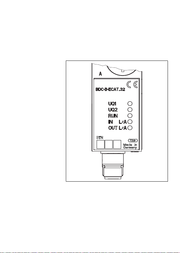
5.2.1 Buskoppler
Abb. 2: Übersicht über den Buskoppler
1 LED-Anzeigen für Diagnosemeldungen
2 BTN-Beschriftungsfeld
3 X71 (BUS IN) Anschluss für den Buskoppler zur Ansteuerung der Ventile
4 X72 (BUS OUT) Anschluss für den Buskoppler
5 X10 (POWER) Anschluss zur Spannungsversorgung der Elektronik und der
Ventilspulen
6 Schraubkappe A: DIP-Schalter S1 (Diagnose-Einstellungen)
7 Schraubkappe B: Schiebeschalter S2 (Ventilzuordnung und Versorgungsspannung)
8 FE-Anschluss
9 Tasche für Einsteckschilder (siehe „Ersatzteile und Zubehör“ auf Seite 40)
1)
Steckerbelegung siehe Seite 20 und Seite 22
1)
Deutsch
1)

16 AVENTICS | EtherCAT | R412012792–BDL–001–AB
Montage
Der Buskoppler ist ausschließlich für den Betrieb als
EtherCAT-Adresse Zur Einstellung der EtherCAT-Adresse ist kein Schalter
Übertragungsrate Die Übertragungsrate beträgt 100 MBits/s vollduplex.
Diagnose Die Versorgungsspannungen für die Logik und die Ventil-
Anzahl ansteuerbarer
Ven til e
EtherCAT Alle Vorgaben und Richtlinien zu EtherCAT sind den
Zertifizierung Das Gerät ist nach den Vorgaben der ETG zertifiziert.
Teilnehmer an einem EtherCAT-Bussegment bestimmt.
vorgesehen.
Der Buskoppler unterstützt die automatische
Adressvergabe der EtherCAT-Adresse.
ansteuerung werden überwacht. Wenn die eingestellte
Schwelle der Ventilversorgungen unterschritten wird,
wird ein Diagnosesignal erzeugt und mittels DiagnoseLED und Diagnoseinformation gemeldet.
Der Buskoppler verfügt über 32 Ventilausgänge. Damit ist
die Anzahl der max. ansteuerbaren Ventilspulen begrenzt.
Es können 16 beidseitig betätigte oder 32 einseitig
betätigte Ventile auf diese Weise angesteuert werden. Es
ist auch eine Kombination der Ventile möglich.
Spezifikationen der EtherCAT Technology Group (ETG) zu
entnehmen. Der Buskoppler unterstützt EtherCAT
Release 2.2.0.0. Der Einsatz von Switches oder Routern
ist im EtherCAT-Netzwerk zulässig. EtherCAT unterstützt
Broadcast, Multicast und Querkommunikation zwischen
Slaves. UDP/IP-Datagramme sind ebenfalls möglich.
Der Buskoppler besitzt zwei Anschlüsse Ethernet Twisted
Pair nach 802.3u.
6 Montage
6.1 Buskoppler am VS montieren
Sie erhalten Ihr individuell konfiguriertes Ventilsystem
komplett verschraubt mit allen Komponenten:
W Ventilträger
W Buskoppler
Die Montage des gesamten Ventilsystems ist in der
beiliegenden Betriebsanleitung für das VS ausführlich
beschrieben. Die Einbaulage des montierten VS ist
beliebig. Die Abmessungen des kompletten VS variieren
je nach Modulbestückung (siehe Abb. 3).

AVENTICS | EtherCAT | R412012792–BDL–001–AB 17
135
A + 33
B + 33
933
6.1.1 Abmessungen
Abb. 3: Maßzeichnung Ventilsystem (Buskoppler und Ventile)
Die Maße A und B sind abhängig vom verwendeten
Ventilblock.
Montage
Deutsch
18 AVENTICS | EtherCAT | R412012792–BDL–001–AB
Montage
6.2 Module beschriften
Buskoppler O Beschriften Sie die für den Buskoppler vorgesehene/
verwendete Adresse am Buskoppler im Feld BTN.
Für die Kennzeichnung der Steckanschlüsse sind im
Gehäuse Einstecktaschen für Beschriftungsschilder
(siehe „Ersatzteile und Zubehör“ auf Seite 40) vorhanden.
Abb. 4: Beschriftungsfelder am Buskoppler

AVENTICS | EtherCAT | R412012792–BDL–001–AB 19
Montage
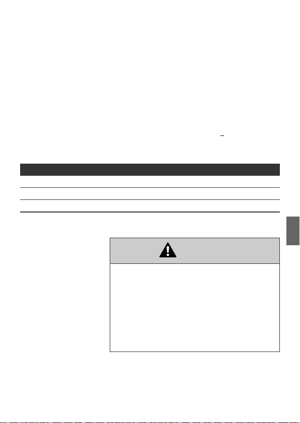
6.3 Buskoppler elektrisch anschließen
VORSICHT
Anliegende elektrische Spannung
Verletzungsgefahr durch elektrischen Schlag.
O Schalten Sie immer den betreffenden Anlagenteil
spannungsfrei und drucklos, bevor Sie am
Ventilträger Module elektrisch anschließen.
ACHTUNG
Falsche Verkabelung
Eine falsche oder fehlerhafte Verkabelung führt zu
Fehlfunktionen und zur Beschädigung Bussystems.
O Halten Sie – sofern nicht anders angegeben – die
Aufbaurichtlinien der EtherCAT Technology Group
(ETG) ein.
O Verwenden Sie nur Kabel, die den Spezifikationen
des Ethernet sowie den Anforderungen bzgl.
Geschwindigkeit und Länge der Verbindung
entsprechen.
O Montieren Sie Kabel und Stecker fachgerecht, damit
Schutzart, Schirmung und Zugentlastung
gewährleistet sind.
Deutsch

20 AVENTICS | EtherCAT | R412012792–BDL–001–AB
Montage
ACHTUNG
Stromfluss durch Potenzialunterschiede am Schirm
Über den Schirm des EtherCAT-Kabels dürfen
durch Potenzialunterschiede bedingten
Ausgleichsströme fließen, da dadurch die Schirmung
aufgehoben wird und die Leitung sowie der
angeschlossene Buskoppler beschädigt werden können.
O Verbinden Sie gegebenenfalls die Massepunkte der
Anlage über eine separate Leitung.
6.3.1 Allgemeine Hinweise zum Anschluss des
Buskopplers
Benutzen Sie für das Anschließen der Module
konfektionierte Steckerverbindungen und Kabel.
O Verwenden Sie D-codierte M12-Stecker für den
Buskoppler.
O Beachten Sie die in Tabelle 5 dargestellte Pin-
Belegung, wenn Sie keine konfektionierten
Steckerverbindungen und Kabel verwenden.
BUS IN
X71
1
1
5
5
434
BUS OUT
X72
1
5
4
2
2
3
2
3
Tabelle 5: Belegung X71 (BUS IN) und X72 (BUS OUT),
M12, D-codiert
Pin Signal Bedeutung
1 TD+ Transmit pos.
2RD+ Receive pos.
3 TD– Transmit neg.
4RD– Receive neg.
5
Gehäuse Schirm- bzw. Funktionserde
X71/ X72: Kommunikationsanschluss
keine
Anschlusstechnik und Steckerbelegung entsprechen
den Vorgaben der technischen Richtlinie.

AVENTICS | EtherCAT | R412012792–BDL–001–AB 21
X71
X72
X10
1
2
X71
X72
X10
1
2
Montage
6.3.2 Buskoppler als Zwischenstation
anschließen
1. Stellen Sie die korrekte Pin-Belegung Ihrer
Steckerverbindungen her, wenn Sie keine
konfektionierte Leitung verwenden (siehe Tabelle 5
auf Seite 20).
2. Schließen Sie die ankommende Busleitung an den
Stecker X71 (BUS IN) an (1).
3. Schließen Sie die abgehende Busleitung an den
Stecker X72 (BUS OUT) an (2).
Das EtherCAT Kabel muss mindestens die
Anforderungen der Kategorie CAT5e erfüllen und
sollte ein doppelt abgeschirmtes Kabel sein (S/STP),
mit einer maximalen Länge von 100 m.
4. Schließen Sie den Schirm an beiden Seiten des
Buskabels direkt an das Steckergehäuse (EMVGehäuse) an, wenn Sie nicht konfektionierte Kabel
und Stecker mit Metallgehäuse verwenden. So
schützen Sie die Datenleitungen gegen
Störungseinkopplungen.
Stellen Sie sicher, dass das Steckergehäuse fest mit
dem Buskopplergehäuse verbunden ist.
Deutsch
6.3.3 Buskoppler als letzte Station anschließen
1. Stellen Sie die korrekte Pin-Belegung (siehe Tabelle 5
auf Seite 20) Ihrer Steckerverbindungen her, wenn
Sie keine konfektionierte Leitung verwenden.
2. Schließen Sie die ankommende Busleitung an den
Stecker X71 (BUS IN) an (1).
3. Versehen Sie die nicht verwendete Gerätedose (2) mit
einer Schutzkappe M12, um den IP-Schutz zu
gewährleisten (siehe Kapitel „Ersatzteile und
Zubehör“ auf Seite 40).
4.
Schließen Sie den Schirm an beiden Seiten des
Buskabels direkt an das Steckergehäuse (EMVGehäuse) an, wenn Sie nichtkonfektionierte Kabel und
Stecker mit Metallgehäuse verwenden. So schützen
Sie die Datenleitungen gegen Störungseinkopplungen.

22 AVENTICS | EtherCAT | R412012792–BDL–001–AB
Montage
Stellen Sie sicher, dass das Steckergehäuse fest mit
dem Buskopplergehäuse verbunden ist.
Ausgleichströme:
Zur Vermeidung von Ausgleichsströmen über den
Schirm des Buskopplers ist zwischen den Geräten
eine Potenzialausgleichsleitung von mindestens
2
erforderlich.
10 mm
Buskabel:
Das EtherCAT-Kabel muss mindestens die
Anforderungen der Kategorie CAT5e erfüllen und
sollte ein doppelt abgeschirmtes Kabel sein (S/STP),
mit einer maximalen Länge von 100 m.
6.3.4 Logik- und Lastversorgung des
Buskopplers anschließen
Über den Gerätestecker X10 (POWER) werden die Ventile
und der Buskoppler versorgt.
Wenn Sie die Logik- und Lastversorgung des Buskopplers
anschließen, müssen Sie die in Tabelle 6 dargestellte PinBelegung sicherstellen.
Tabelle 6: Belegung des Gerätesteckers X10 (POWER),
M12, A-codiert
Pin X10 Belegung
1U
Spannungsversorgung Buskoppler-Logik
L
2UQ1Spannungsversorgung Ventile2)
3 OV Masse für U
4UQ2Spannungsversorgung Ventile2)
1)
Versorgungsspannung (Pin1) muss mit einer externen
Sicherung (500 mA, F) abgesichert werden.
2)
Beide Versorgungsspannungen (Pin2, Pin4) müssen jeweils mit
einer externen Sicherung (3 A, F) abgesichert werden.
2
POWER
X10
1
43
L, UQ1
und U
1)
Q2
W UL, UQ1 und UQ2 sind galvanisch miteinander
verbunden.
W Über die Ventilversorgung U
Ventile byteweise (entspricht je 4 beidseitig
Q1
und U
können die
Q2
AVENTICS | EtherCAT | R412012792–BDL–001–AB 23
betätigten Ventilen oder 8 einseitig betätigten
Ventilen) abgeschaltet werden.
W Die Zuordnung der Ventilgruppen (4 oder 8 Ventile)
erfolgt über die Schiebeschalter S2 (siehe
„Ventilversorgung auswählen“ auf Seite 27). Dadurch
ist z. B. eine separate Abschaltung möglich.
Das Kabel für die Lastversorgung muss folgende
Anforderungen erfüllen:
W Kabelbuchse: 4-polig, A-codiert ohne Mittelloch
W Leitungsquerschnitt an Gesamtstrom und
Leitungslänge anpassen: je Ader >
W Länge: max. 20 m
Tabelle 7: Stromaufnahme an X10 (POWER) am Buskoppler
Signal Belegung Gesamtstrom
U
L
U
Q1
U
Q2
1)
Der Summenstrom in der 0-V-Leitung darf 4 A nicht überschreiten.
Logik, Eingänge max. 0,5 A
Ventile max. 3 A
Ventile max. 3 A
1)
1)
VORSICHT
Gefährliche Spannungen
Ein Netzteil mit nicht sicherer Trennung kann im
Fehlerfall zu gefährlichen Spannungen führen.
Verletzungen durch Stromschlag und Schädigung des
Systems können die Folgen sein.
O Verwenden Sie nur ein Netzteil mit einer sicheren
Trennung nach EN 60747, Klassifikation VDE 0551!
Damit gelten die entsprechenden Stromkreise als
SELV/PELV-Stromkreise nach IEC 60364-4-41.
Montage
0,5 mm2
Deutsch
So schließen Sie die Lastversorgung des Buskopplers an:
1.
Stellen Sie die korrekte Pin-Belegung (siehe Tabelle 6
auf Seite 22) Ihrer Steckerverbindungen her, wenn Sie
keine konfektionierte Anschlussleitung verwenden.

24 AVENTICS | EtherCAT | R412012792–BDL–001–AB
1
Montage
2. Schließen Sie mit dem Steckerverbinder (siehe
„Ersatzteile und Zubehör“ auf Seite 40) die
Betriebsspannungen an den Buskoppler an.
3. Kontrollieren Sie die Spezifikationen der
Betriebsspannungen anhand der elektrischen
Kenngrößen und halten Sie diese ein (siehe Kapitel
„Technische Daten“ auf Seite 39).
4. Stellen Sie die Leistungen gemäß Tabelle 7 auf
Seite 22 bereit. Wählen Sie die Kabelquerschnitte
entsprechend der Kabellänge und der auftretenden
Ströme.
6.3.5 FE-Anschluss
Erdung am
Buskoppler
O Verbinden Sie zur Ableitung von EMV-Störungen den
FE-Anschluss (1) am Buskoppler über eine
niederimpedante Leitung (mit geringem Widerstand)
mit der Funktionserde (FE).
Empfohlener Kabelquerschnitt: 10 mm
2
Abb. 5: FE-Anschluss am Buskoppler (1)

AVENTICS | EtherCAT | R412012792–BDL–001–AB 25
A
B
S1
S1.1
S1.5
Inbetriebnahme und Bedienung
7 Inbetriebnahme und
Bedienung
7.1 Voreinstellungen vornehmen
Folgende Voreinstellungen müssen Sie durchführen:
W Ventilversorgung auswählen
W Diagnosemeldungen einstellen
Alle diese Einstellungen erfolgen über die Schalter unter
den Verschraubungen A und B.
Gehen Sie bei allen Voreinstellungen wie folgt vor:
1. Drehen Sie die Verschraubung ab.
2. Nehmen Sie die entsprechende Einstellung wie
nachfolgend beschrieben vor.
3. Drehen Sie die Verschraubung wieder ein
(0,6 + 0,2 Nm). Achten Sie hierbei auf den korrekten
Sitz der Dichtungsringe
7.1.1 Diagnosemeldungen einstellen
Der Mode-Schalter S1 für die Einstellung der
Diagnosemeldungen befindet sich unter der
Verschraubung A.
Deutsch
Der Auslieferungszustand ist EtherCAT-konform.
Die Diagnose ist deaktiviert (S1.1 auf OFF).
Die Diagnosemeldungen werden als General Purpose
Inputs (GPI) an die Steuerung übertragen.
O Aktivieren oder deaktivieren Sie die
Diagnosemeldungen der GPI [10-14] mit dem
Schalter S1.1.
Die geänderte Schalterstellung wird erst nach einem
erneuten „Power-on“ aktiviert.
Auch bei ausgeschalteter Diagnosemeldung werden
anstehende Diagnosen auf den LEDs angezeigt.

26 AVENTICS | EtherCAT | R412012792–BDL–001–AB
Inbetriebnahme und Bedienung
Tabelle 8: S1, Überwachungsschwelle für Ventilspannung festlegen
Schalter/
Bit
1.1 OFF
1.2 OFF1): 12,5 V < UQ1 < 21,6 V/20,4 V
1.3 OFF
1.4 OFF
Diagnose Hinweise
1)
: Überlast, Ventiltreiber
ausgeschaltet
2)
ON
: Überlast, Ventiltreiber
eingeschaltet
Diagnosemeldung, wenn ein Ventil
Überlast bzw. Kurzschluss
aufweist. Die Diagnosemeldung ist
nur vorhanden, solange dieses
Ventil angesteuert ist.
Um ein sicheres Schalten der
ausgeschaltet
2)
: 12,5 V < UQ1 < 21,6 V/20,4 V
ON
eingeschaltet
1)
: 12,5 V < UQ2 < 21,6 V/20,4 V
ausgeschaltet
2)
ON
: 12,5 V < UQ2 < 21,6 V/20,4 V
eingeschaltet
1)
: Meldung UQ1 < 12,5 V
ausgeschaltet
2)
ON
: Meldung UQ1 < 12,5 V
Ventile zu gewährleisten, muss die
Schaltspannung 20,4 V bzw. 21,6 V
betragen!
Unterspannung bei den Ventilen
liegt vor, wenn die Spannung UQ
zwischen 12,5 V und 20,4 V/21,6 V
liegt. Die Unterspannungsmeldung
erscheint beim Einschalten nach ca.
10 ms und beim Ausschalten nach
ca. 20 ms. Tritt eine Spannung
kleiner als 12,5 V auf, wird dieses
gesondert gemeldet.
eingeschaltet
1.5 OFF
1)
: Meldung UQ2 < 12,5 V
ausgeschaltet
2)
ON
: Meldung UQ2 < 12,5 V
eingeschaltet
1.6 OFF Service-Schalter (default: OFF)
1.7 OFF
1.8 OFF
1)
deaktiviert
2)
aktiviert
1)
: Schwelle für UQ1 ist 20,4 V Für unterschiedliche Ventilserien
2)
ON
: Schwelle für UQ1 ist 21,6 V
1)
: Schwelle für UQ2 ist 20,4 V
2)
ON
: Schwelle für UQ2 ist 21,6 V
kann die Schwelle 20,4 V/21,6 V
angepasst werden.

AVENTICS | EtherCAT | R412012792–BDL–001–AB 27
4321
DCBA
S2.4
S2.1
2*
1*
* Schalterstellung
Inbetriebnahme und Bedienung
7.1.2 Umschalten der Toleranzpegel der
Ventilversorgung U
Für die unterschiedlichen Ventilserien kann die
Überwachungsschwelle zwischen 20,4 V und 21,6 V
umgeschaltet werden (siehe 8 auf Seite 26). Im
Auslieferungszustand ist die Schwelle auf 21,6 V (10 %)
eingestellt (S1.7/1.8 auf OFF). Sinkt die
Versorgungsspannung für die Ventilansteuerung unter
diese Schwelle, wird eine Diagnosemeldung erzeugt.
Q1
und U
Q2
7.1.3 Ventilversorgung auswählen
Mit dem Schiebeschalter S2 (unter Verschraubung B)
kann die Ventilspannungsversorgung blockweise
ausgewählt werden. Es kann zwischen den Spannungen
und UQ2 aus der externen Versorgung umgeschaltet
U
Q1
werden.
Alle Schalter befinden sich im Auslieferungszustand
in der Stellung 1.
Deutsch
ACHTUNG
Spannung an Schaltern
Schalter können beschädigt werden, wenn bei ihrer
Bedienung eine Spannung anliegt.
O Betätigen Sie die Schalter nur in spannungsfreiem
Zustand!
O Wählen Sie die Schalterstellung von S2 gemäß
nachfolgender Tabelle.

28 AVENTICS | EtherCAT | R412012792–BDL–001–AB
Inbetriebnahme und Bedienung
Tabelle 9: Zuordnung der Schalter S2
Schieber Funktion Schalterstellung 1 Schalterstellung 2
2.1 Spannungsversorgung
Ansteuerbyte 1
2.2 Spannungsversorgung
Ansteuerbyte 2
2.3 Spannungsversorgung
Ansteuerbyte 3
2.4 Spannungsversorgung
Ansteuerbyte 4
U
(externe Versorgung,
Q1
PIN 2, weiß)
U
(externe Versorgung,
Q1
PIN 2, weiß)
U
(externe Versorgung,
Q1
PIN 2, weiß)
U
(externe Versorgung,
Q1
PIN 2, weiß)
U
(externe Versorgung,
Q2
PIN 4, schwarz)
UQ2
(externe Versorgung,
PIN 4, schwarz)
UQ2
(externe Versorgung,
PIN 4, schwarz)
UQ2
(externe Versorgung,
PIN 4, schwarz)
So ordnen Sie die Ventilversorgung zu:
1. Öffnen Sie die Schraubkappe B (siehe Abbildung auf
Seite 25).
2. Ordnen Sie mit Hilfe des Schalters S2 jeder
Ventilgruppe eine der beiden
Versorgungsspannungen U
Abbildung auf Seite 27 und Tabelle 9).
oder UQ2 zu (siehe
Q1
Für die Zuordnung des Schalters S2 und der Versorgung
montierter Ventile finden Sie die Beispiele für
32 Ventilspulen in den Tab. 10 und Tab. 11 auf den Seiten
30 und 31 (jeweils Beispiele 1 bis 3 und Beispiele 4 bis 6).

AVENTICS | EtherCAT | R412012792–BDL–001–AB 29
Inbetriebnahme und Bedienung
Darin sind folgende Beispielkombinationen aufgeführt:
1)
Beispiele
Beispiel 1 Anschlussplatten für beidseitig
Verwendete Anschlussplatten Ventilbestückung
beidseitig betätigte Ventile
betätigte Ventile
Beispiel 2 Anschlussplatten für beidseitig
einseitig betätigte Ventile
betätigte Ventile
Beispiel 3 Anschlussplatten für beidseitig
betätigte Ventile
Beispiel 4 Anschlussplatten für einseitig
ein- und beidseitig betätigte
Ventile
einseitig betätigte Ventile
betätigte Ventile
Beispiel 5 Anschlussplatten für beidseitig
beidseitig betätigte Ventile
betätigte Ventile
kombiniert mit
Anschlussplatten für einseitig
einseitig betätigte Ventile
betätigte Ventile
Beispiel 6 Anschlussplatten für beidseitig
betätigte Ventile
ein- und beidseitig betätigte
Ventile
kombiniert mit
Anschlussplatten für einseitig
einseitig betätigte Ventile
betätigte Ventile
1)
Entsprechend Ihren Anforderungen können Sie auch andere Kombinationen wählen.
Von der elektrischen Anschlussseite aus betrachtet
müssen zuerst die Anschlussplatten für beidseitig
betätigte Ventile und danach die für einseitig
betätigte Ventile angeordnet werden. Die maximale
Spulenzahl bezogen auf alle Anschlussplatten
beträgt 32.
Die Zuordnung von Schaltern und
Ventilversorgungen ändert sich beim Einsatz von
Modulerweiterungen (siehe Betriebssanleitung
R412008961). Dies gilt auch für die folgenden
Beispiele in Tabelle 10 und Tabelle 11.
Deutsch

30 AVENTICS | EtherCAT | R412012792–BDL–001–AB
Inbetriebnahme und Bedienung
Tabelle 10: Beispiele für die Zuordnung von Schaltern und Ventilversorgung,
32 Ventilspulen
Beispiel 1 Beispiel 2 Beispiel 3
Anschlussplatte für beidseitig betätigte Ventile
Ventil-
Byte
Schalter
S2.1 0 A0.0 1 14
Adresse
platz
1)
Spule LED
Ventilplatz
1)
Spule LED
Ventilplatz
1)
114114
A0.1 12 – 12
A0.2 2 14
214214
A0.3 12 – 12
A0.4 3 14
314314
A0.5 12 – 12
A0.6 4 14
414414
A0.7 12 – 12
S2.2 1 A1.0 5 14
514514
A1.1 12 – 12
A1.2 6 14
614614
A1.3 12 – –
A1.4 7 14
714714
A1.5 12 – –
A1.6 8 14
814814
A1.7 12 – –
S2.3 2 A2.0 9 14
914914
A2.1 12 –
A2.2 10 14
10 14 10 14
A2.3 12 – 12
A2.4 11 14
11 14 11 14
A2.5 12 – 12
A2.6 12 14
12 14 12 14
A2.7 12 – –
S2.4 3 A3.0 13 14
13 14 13 14
A3.1 12 – –
A3.2 14 14
14 14 14 14
A3.3 12 – 12
A3.4 15 14
15 14 15 14
A3.5 12 – 12
A3.6 16 14
16 14 16 14
A3.7 12 – –
1)
Weiße Felder kennzeichnen Ventilplätze mit beidseitig betätigten Ventilen.
Grau unterlegte Felder kennzeichnen Ventilplätze mit einseitig betätigten Ventilen.
Spule LED
AVENTICS | EtherCAT | R412012792–BDL–001–AB 31
Inbetriebnahme und Bedienung
Tabelle 11: Beispiele für die Zuordnung von Schaltern und Ventilversorgung,
32 Ventilspulen
Beispiel 4 Beispiel 5 Beispiel 6
Anschlussplatte für
einseitig betätigte
Byte
Schalter
Adresse
S2.1 0 A0.0
A0.1
A0.2
A0.3
A0.4
A0.5
A0.6
A0.7
S2.2 1 A1.0
A1.1
A1.2
A1.3
A1.4
A1.5
A1.6
A1.7
S2.3 2 A2.0
A2.1
A2.2
A2.3
A2.4
A2.5
A2.6
A2.7
S2.4 3 A3.0
A3.1
A3.2
A3.3
A3.4
A3.5
A3.6
A3.7
1)
Weiße Felder kennzeichnen Ventilplätze mit beidseitig betätigten Ventilen.
Grau unterlegte Felder kennzeichnen Ventilplätze mit einseitig betätigten Ventilen.
Ventile
Ventil-
Spule LED
1)
platz
114114114
214 12 12
314214214
414 12 –
514314314
614 12 –
714414414
814 12 12
914514514
10 14 614 12
11 14 714614
12 14 814 12
13 14 914714
14 14 10 14 814
15 14 11 14 914
16 14 12 14 10 14
17 14 13 14 11 14
18 14 14 14 12 14
19 14 15 14 13 14
20 14 16 14 14 14
21 14 17 14 15 14
22 14 18 14 16 14
23 14 19 14 17 14
24 14 20 14 18 14
25 14 21 14 19 14
26 14 22 14 20 14
27 14 23 14 21 14
28 14 24 14 22 14
29 14 25 14 23 14
30 14 26 14 24 14
31 14 27 14 25 14
32 14 28 14 26 14
Anschlussplatte für ein- und beidseitig
betätigte Ventile
Ventilplatz
1)
Spule LED
Ventilplatz
1)
Spule LED
Deutsch

32 AVENTICS | EtherCAT | R412012792–BDL–001–AB
Inbetriebnahme und Bedienung
7.2 Buskoppler konfigurieren
Die in diesem Abschnitt dargestellten
Konfigurierungsschritte sind den bereits beschriebenen
Einstellungen am Buskoppler (siehe „Voreinstellungen
vornehmen“ auf Seite 25) übergeordnet und Teil der
Busmasterkonfiguration des Gesamtsystems.
Die beschriebenen Arbeiten dürfen nur von einer
Elektronikfachkraft und unter Beachtung der
Dokumentation des Betreibers zur Konfiguration des
Busmasters sowie der geltenden technischen
Normen, Richtlinien und Sicherheitsvorschriften
durchgeführt werden.
Vor der Konfiguration müssen Sie folgende Arbeiten am
Buskoppler durchgeführt und abgeschlossen haben:
W Sie haben den Buskoppler und das Ventilträger
montiert (siehe „Montage“ auf Seite 16).
W Sie haben den Buskoppler angeschlossen (siehe
„Buskoppler elektrisch anschließen“ auf Seite 19).
W Sie haben die Voreinstellungen vorgenommen
(siehe „Voreinstellungen vornehmen“ auf Seite 25).
ACHTUNG
Konfigurationsfehler
Ein fehlerhaft konfigurierter Buskoppler kann zu
Fehlfunktionen im System führen und eine Schädigung
des Systems zur Folge haben.
O Die Konfiguration darf daher nur von einer
Elektronikfachkraft durchgeführt werden!
O Konfigurieren Sie das Bussystem gemäß Ihren
Systemanforderungen, den Vorgaben des Herstellers
und allen geltenden technischen Normen, Richtlinien
und Sicherheitsvorschriften. Beachten Sie dabei die
Dokumentation des Betreibers zur Konfiguration
des Busmasters.

AVENTICS | EtherCAT | R412012792–BDL–001–AB 33
Inbetriebnahme und Bedienung
Das Betriebsverhalten, die relevanten Objekte und
Parameter zur Konfiguration des Buskopplers, mögliche
Einstellungen als Beispiele sowie der Funktionsumfang
sind im Kapitel „Anhang Angaben zur
Busmasterkonfiguration mit EtherCAT“ ab Seite 41
aufgeführt.
7.3 Test und Diagnose am
Buskoppler
7.3.1 Diagnoseanzeige am Buskoppler ablesen
Die LEDs auf der Frontplatte des Buskopplers geben die
in Tabelle 12 aufgeführten Meldungen wieder.
O Überprüfen Sie vor Inbetriebnahme und während des
Betriebs regelmäßig die Buskopplerfunktionen durch
Ablesen der Diagnoseanzeigen.
Tabelle 12: Bedeutung der Diagnose-LEDs am Buskoppler
LED Signal Beschreibung
grün Ventilversorgung UQ1 in Ordnung
U
Q1
rot Unterspannung (12 V < U
aus Ventilversorgung U
grün Ventilversorgung UQ2 in Ordnung
U
Q2
rot Unterspannung (12 V < U
aus Ventilversorgung U
RUN grün Operational
grün, blinkt Preoperational
grün, Blitz Safeoperational
grün, schnell
Bootstrap
blinkend
aus INIT
L0/A0grün, schnell
blinkend
Verbindung ("Link") und Datenaustausch ("Activity")
mit Teilnehmer an Stecker X71
grün Verbindung ("Link") zu einem Teilnehmer an Stecker X71
aus
L1/A1grün, schnell
blinkend
keine Verbindung ("Link") zu einem Teilnehmer an Stecker X71
Verbindung ("Link") und Datenaustausch ("Activity")
mit Teilnehmer an Stecker X72
grün Verbindung ("Link") zu einem Teilnehmer an Stecker X72
aus
keine Verbindung ("Link") zu einem Teilnehmer an Stecker X72
< 21,6 V/20,4 V (S3.4))
Q1
< 12 V
Q1
< 21,6 V/20,4 V (S3.4))
Q2
< 12 V
Q2
Deutsch

34 AVENTICS | EtherCAT | R412012792–BDL–001–AB
Inbetriebnahme und Bedienung
Tabelle 13: Bedeutung der General Purpose Inputs (GPI)
GPI [...] Bedeutung der Bits
0 Schalter S1.2 OPEN / CLOSE
1 Schalter S1.3 OPEN / CLOSE
2 Schalter S1.4 OPEN / CLOSE
3 Schalter S1.5 OPEN / CLOSE
4 ON Unterspannung (U
OFF Ventilversorgung U
5 ON Unterspannung (U
OFF Ventilversorgung U
6ONVentilversorgung U
OFF Ventilversorgung U
7ONVentilversorgung U
OFF Ventilversorgung U
< 21,6 V/20,4 V (S1.7))
Q1
in Ordnung
Q1
< 21,6 V/20,4 V (S1.7))
Q2
in Ordnung
Q2
< 12 V
Q1
> 12 V
Q1
< 12 V
Q2
> 12 V
Q2
8 Schalter S1.1 OPEN / CLOSE
9 ON Kurzschluss / OpenLoop Ventilspule
OFF Keine Ventilspulendiagnosemeldung
10 ON Schalter S1.5 CLOSE
und Unterspannung (12 V < U
OFF Ventilversorgung U
Q1
Q2
in Ordnung
11 ON Schalter S1.4 CLOSE
und Unterspannung (12 V < U
OFF Ventilversorgung U
Q1
Q2
in Ordnung
12 ON Schalter S1.3 CLOSE
Q1
Q1
> 12 V
< 12 V
und Ventilversorgung U
OFF Ventilversorgung U
13 ON Schalter S1.2 CLOSE
und Ventilversorgung U
OFF Ventilversorgung U
Q2
Q2
> 12 V
< 12 V
14 ON Schalter S1.1 CLOSE
und Kurzschluss / OpenLoop Ventilspule
OFF Keine Ventilspulendiagnosemeldung
15 GPO [15] OFF (default)
ON Service
< 21,6 V/20,4 V (S1.7))
< 21,6 V/20,4 V (S1.8))

AVENTICS | EtherCAT | R412012792–BDL–001–AB 35
Inbetriebnahme und Bedienung
7.4 Buskoppler in Betrieb nehmen
Bevor Sie das System in Betrieb nehmen, müssen Sie
folgende Arbeiten durchgeführt und abgeschlossen haben:
W Sie haben den Ventilträger und den Buskoppler
montiert (siehe „Buskoppler am VS montieren“ auf
Seite 16).
W Sie haben den Buskoppler angeschlossen (siehe
„Buskoppler elektrisch anschließen“ auf Seite 19).
W Sie haben die Voreinstellungen und die Konfiguration
durchgeführt (siehe „Voreinstellungen vornehmen“
auf Seite 25).
W Sie haben den Busmaster so konfiguriert, dass die
Ventile richtig angesteuert werden.
Die Inbetriebnahme und Bedienung darf nur von
einer Elektro- oder Pneumatikfachkraft oder von
einer unterwiesenen Person unter der Leitung und
Aufsicht einer Fachkraft erfolgen (siehe
„Qualifikation des Personals“ auf Seite 9).
VORSICHT
Unkontrollierte Bewegungen der Aktoren beim
Einschalten der Pneumatik
Es besteht Verletzungsgefahr, wenn sich das System
in einem undefinierten Zustand befindet und wenn die
Handhilfsbetätigungen auf Position „1“ stehen.
O Bringen Sie das System in einen definierten
Zustand, bevor Sie es einschalten!
O
Stellen Sie alle Handhilfsbetätigungen auf Position „0“.
O Stellen Sie sicher, dass sich keine Person innerhalb
des Gefahrenbereichs befindet, wenn Sie die
Druckluftversorgung einschalten.
O
Beachten Sie auch die entsprechenden Anweisungen
und Warnhinweise der Betriebsanleitung Ihres VS.
1. Schalten Sie die Betriebsspannung ein.
2. Überprüfen Sie die LED-Anzeigen an allen Modulen.
3. Schalten Sie die Druckluftversorgung ein.
Deutsch
36 AVENTICS | EtherCAT | R412012792–BDL–001–AB
1
2
3
4
Demontage und Austausch
8 Demontage und Austausch
Sie können je nach Bedarf den Buskoppler austauschen.
Die Gewährleistung von AVENTICS gilt nur für die
ausgelieferte Konfiguration und Erweiterungen, die
bei der Konfiguration berücksichtigt wurden. Nach
einem Umbau, der über diese Erweiterungen
hinausgeht, erlischt die Gewährleistung.
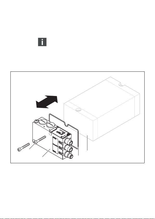
8.1 Buskoppler austauschen
Abb. 6: Buskoppler austauschen, Beispiel
1 Innensechskantschrauben M4x35
2 Buskoppler
3 Dichtung
4 EP-Endplatte VS

AVENTICS | EtherCAT | R412012792–BDL–001–AB 37
Demontage und Austausch
VORSICHT
Anliegende elektrische Spannung und hoher Druck
Verletzungsgefahr durch elektrischen Schlag und
plötzlichen Druckabbau.
O
Schalten Sie das System drucklos und spannungsfrei.
O Beachten Sie beim Umgang mit ESD-empfindlichen
Baugruppen die vorgeschriebenen
Vorsichtsmaßnahmen.
So tauschen Sie den Buskoppler aus:
1. Trennen Sie die elektrischen Anschlüsse vom
Buskoppler (2).
2. Lösen Sie den Buskoppler (2)
(je 2 Innensechskantschrauben DIN 912 – M4 (1),
Schlüsselweite 4).
3. Ziehen Sie den Buskoppler (2) von der EP-Endplatte
(4) ab.
4. Schieben Sie den neuen Buskoppler (2) auf die
EP-Endplatte (4) auf.
5. Stellen Sie sicher, dass die Dichtung (3) richtig
eingelegt ist.
6. Schrauben Sie den Buskoppler (2) an
(je 2 Innensechskantschrauben DIN 912 – M4 (1),
Schlüsselweite 4). Anzugsdrehmoment: 3,0 + 0,5 Nm.
7. Führen Sie alle Voreinstellungen am neuen
Buskoppler (2) durch (siehe „Voreinstellungen
vornehmen“ auf Seite 25).
8. Stellen Sie die Anschlüsse wieder her.
9. Überprüfen Sie die Konfiguration und passen Sie
diese gegebenenfalls an (siehe „Buskoppler
konfigurieren“ auf Seite 32).
Deutsch

38 AVENTICS | EtherCAT | R412012792–BDL–001–AB
Pflege und Wartung
9 Pflege und Wartung
VORSICHT
Anliegende elektrische Spannung und hoher Druck!
Verletzungsgefahr durch elektrischen Schlag und
plötzlichen Druckabbau.
O Schalten Sie das System vor der Durchführung von
Pflege- und Wartungsarbeiten drucklos und
spannungsfrei.
9.1 Module pflegen
ACHTUNG
Beschädigung der Gehäuseoberfläche durch
Lösemittel und aggressive Reinigungsmittel!
Die Oberflächen und Dichtungen können durch
Lösemittel oder aggressive Reinigungsmittel
beschädigt werden.
O Verwenden Sie niemals Lösemittel oder aggressive
Reinigungsmittel!
O Reinigen Sie das Gerät regelmäßig mit einem
feuchten Lappen. Verwenden Sie dazu nur Wasser
oder ein mildes Reinigungsmittel.
9.2 Buskoppler warten
Der Buskoppler ist wartungsfrei.
O Beachten Sie die Wartungsintervalle und Vorgaben
der Gesamtanlage.

AVENTICS | EtherCAT | R412012792–BDL–001–AB 39
Technische Daten
10 Technische Daten
10.1 Kenngrößen
Allgemein
Schutzart nach
EN 60 529 / IEC 529 IP65 im montierten Zustand
Umgebungstemperatur
W Betrieb
W Lagerung
Elektromagnetische Verträglichkeit
Störfestigkeit EN 61000-6-2
Störaussendung EN 61000-6-4
Elektrik
Betriebsspannung
W Logik
–U
L
–I
L
–Absicherung der Logikspannung 500 mAF
W Last U
Leitungslänge der Spannungsversorgung max. 20 m
Maximaler Strom in der 0-V-Leitung 4 A
Spannungsabfall intern 0,6 V
Max. Ausgangsstrom je Ventilausgang 100 mA
Anzahl der Ausgänge 32
Anzahl der Ausgangsbytes
Hochlaufzeit ca. 2 s
, U
Q1
Q2
–Absicherung der Spannungsversorgung
U
10.2 Buskoppler
0 C bis +50 °C ohne Betauung
–20 °C bis +70 °C
24 V DC (+20 %/–15 %)
100 mA
24 V DC (10 %/15 %)
Schutzkleinspannung (SELV/PELV)
nach EC 364-4-41
Restwelligkeit 0,5 %
jeweils 3,0 AF
fest 4 Byte Ausgang und 0 Byte Eingang
Deutsch

40 AVENTICS | EtherCAT | R412012792–BDL–001–AB
Ersatzteile und Zubehör
11 Ersatzteile und Zubehör
11.1 Buskoppler
Bestellnummer
Buskoppler mit Feldbusprotokoll EtherCAT
mit Ansteuerung für 32 Ventilspulen
Zubehör
Satz: Dichtung, 2 Schrauben M4, 1 Schraube FE R412008885
10x Verschlussschraube, metrisch R412008886
5x Karten-Einsteckschilder R412008887
M12x1 Schutzkappe 1823312001
1)
Lieferung inkl. 2 Innensechskantschrauben, Dichtung und Handbuch
1)
R412009573
11.2 Power-Stecker für Buskoppler
Bestellnummer
Steckverbinder für Spannungsversorgung,
Kupplung M12x1, 4-polig für Leitungs-Ø
4 – 8 mm, A-codiert
180° (X10, POWER) 8941054324
90° (X10, POWER) 8941054424
12 Entsorgung
Entsorgen Sie das Gerät nach den Bestimmungen des
Verwenderlandes.

Verhalten nach
Power-on
AVENTICS | EtherCAT | R412012792–BDL–001–AB 41
Anhang
13 Anhang
13.1 Angaben zur
Busmasterkonfiguration
mit EtherCAT
Beim Buskoppler handelt es sich um ein Ausgangsmodul
mit festeingestellten 32 digitalen Ausgängen. Zur
Konfiguration und Administration sind daher nur wenige
Schritte notwendig.
13.2 Betriebsverhalten
Pro Anschaltung können 4 Byte Master-Echtzeit-Daten
(Ausgänge) verarbeitet werden. Zusätzlich werden
Diagnosedaten als General Purpose Inputs (GPI)
übertragen. Die Datenlänge der GPIs und GPOs beträgt
jeweils 2 Byte (16 Bit). Der Buskoppler verfügt über keine
Distributed Clock (DC) Fähigkeiten.
13.3 Anlaufverhalten
Nach dem Einschalten der Baugruppe (Anlegen der 24-VLogikversorgung) werden die Hardwarekomponenten
getestet (Startup-Test).
Ist der Startup-Test erfolgreich durchlaufen und die
Busspannung vorhanden, wird der Buskoppler gemäß
den Voreinstellungen an den Dreh-und DIP-Schaltern
initialisiert.
Die Baugruppe befindet sich nach erfolgreicher
Initialisierung im INIT-Mode, bis der Master die
Kommunikation aufbaut. Sie kann nun von der EtherCATSteuerung in die verschiedenen Modi bis zum Zustand
"Operational" geschaltet werden.
Deutsch

42 AVENTICS | EtherCAT | R412012792–BDL–001–AB
Anhang
13.4 Konfigurationsdatei
Die Datei ist eine von der EtherCAT Technology Group
(ETG) spezifizierte ASCII-Datei im Extensible-MarkupLanguage-Format (XML), in der die Objekte/
Leistungsmerkmale eines EtherCAT-Geräts beschrieben
sind. Für den Buskoppler gibt es diese Datei mit dem
Dateinamen BDC_ECAT32.XML.
Diese kann unter www.aventics.com/mediadirectory
heruntergeladen werden.

AVENTICS | EtherCAT | R412012792–BDL–001–AB 43
14 Stichwortverzeichnis
Stichwortverzeichnis
W A
Abkürzungen 7
W B
Baudrate einstellen 25
Beschriftung
Modul 18
Betriebsverhalten,
Busanschaltung 41
Buskoppler
Aufbau 15
austauschen 36
Ersatzteile, Zubehör 40
in Betrieb nehmen 35, 36
Technische Daten 39
Test und Diagnose 33
Busmasterkonfiguration 41
W D
Diagnose
einstellen 25
Diagnoseanzeige, Buskoppler 33
W E
Elektrischer Anschluss
Buskoppler als letzte Station 21
Buskoppler als
Zwischenstation 21
FE 24
Logik und Lastversorgung 22
Schirmung 21
Entsorgung 40
Ersatzteile 40
W G
Gebrauch
bestimmungsgemäß 8
nicht bestimmungsgemäß 8
W I
Inbetriebnahme
Diagnoseanzeige 33
Voreinstellungen 25
W K
Kenngrößen 39
Komponenten
Buskoppler 15
Konfiguration, Busmaster 41
Konfigurationsdatei 42
W M
Mode-Schalter 25
Montage
FE-Anschluss 24
Montagemöglichkeiten 16
W N
Normen 11
W Q
Qualifikation, Personal 9
W S
Schalter
S2 27
Sicherheitshinweise
allgemein 10
Reinigung 12
Steckerverbindungen
X10 (POWER) 22
W T
Test und Diagnose
Buskoppler 33
W V
Ventilversorgung auswählen 27
Voreinstellungen
Baudrate einstellen 25
Diagnose 25
Diagnosemeldungen einstellen 25
Deutsch

44 AVENTICS | EtherCAT | R412012792–BDL–001–AB
Stichwortverzeichnis
W W
Warnhinweise, Definitionen 6
W Z
Zubehör 40

AVENTICS | EtherCAT | R412012792–BDL–001–AB 45
Contents
Contents
1 About this documentation ............................ 47
1.1 Documentation validity.........................................47
1.2 Required and supplementary documentation ..47
1.3 Presentation of information ................................47
1.3.1 Safety instructions ............................................... 48
1.3.2 Symbols ................................................................... 48
1.3.3 Abbreviations ......................................................... 49
2 Safety instructions ........................................ 50
2.1 About this chapter..................................................50
2.2 Intended use.............................................................50
2.3 Improper use............................................................50
2.4 Personnel qualifications....................................... 51
2.5 General safety instructions ................................. 51
2.6 Safety instructions related to the product
and technology........................................................52
3 Applications ................................................... 53
4 Delivery contents .......................................... 54
5 Device description ......................................... 54
5.1 Total overview of the valve system................... 55
5.2 Device components................................................56
5.2.1 Bus coupler ............................................................ 56
6 Assembly ....................................................... 57
6.1 Assembling the valve system with the
bus coupler...............................................................57
6.1.1 Dimensions ............................................................. 58
6.2 Labeling the module..............................................58
6.3 Connecting the bus coupler electrically..........59
6.3.1 General notes on connecting the
bus coupler ............................................................. 60
6.3.2 Connecting the bus coupler as an
intermediate station ............................................ 61
6.3.3 Connecting the bus coupler as a
final station ............................................................. 62
6.3.4 Connecting the bus coupler logic and
load supply ............................................................. 62
6.3.5 FE connection ........................................................ 64
English

46 AVENTICS | EtherCAT | R412012792–BDL–001–AB
Contents
7 Commissioning and operation ..................... 65
7.1 Making settings.......................................................65
7.1.1 Setting diagnostic messages ............................ 66
7.1.2 Switching the tolerance level for U
U
valve supply .................................................... 68
7.1.3 Selecting the valve supply ................................. 68
7.2 Configuring the bus coupler................................ 74
7.3 Testing and diagnosis on the bus coupler ......75
7.3.1 Reading the diagnostic display on the
7.4 Commissioning the bus coupler ........................77
8 Disassembly/exchange ................................ 78
8.1 Exchanging the bus coupler................................ 79
9 Service and maintenance ............................. 81
9.1 Servicing the modules ..........................................81
9.2 Maintaining the bus coupler................................81
10 Technical data ............................................... 82
10.1 Characteristics ........................................................82
10.2 Bus coupler...............................................................82
11 Spare parts and accessories ....................... 83
11.1 Bus coupler...............................................................83
11.2 Power plug for bus coupler.................................83
12 Disposal .......................................................... 83
13 Appendix ........................................................ 84
13.1 Information on the bus master
13.2 Operating behavior.................................................84
13.3 Start-up behavior ...................................................84
13.4 Configuration file ....................................................84
Q2
bus coupler ............................................................. 75
configuration with EtherCAT ............................... 84
14 Index ............................................................... 85
and
Q1

AVENTICS | EtherCAT | R412012792–BDL–001–AB 47
About this documentation
1 About this documentation
1.1 Documentation validity
This documentation contains important information on
the safe and appropriate assembly, operation, and
maintenance of the bus coupler and how to remedy
simple malfunctions yourself.
O Read this documentation completely, especially
chapter “Safety instructions”, before working with the
bus coupler.
1.2 Required and supplementary
documentation
O Only commission the product once you have obtained
the following documentation and understood and
complied with its contents.
Table 1: Required and supplementary documentation
Title Document number Document type
Documentation of the
valve system HF03 LG
Documentation of the
valve system HF04 D-SUB
System documentation
R412008233 Instructions
R412015493 Instructions
Further information on the components can be found in
the online catalog at
www.aventics.com/pneumatics-catalog.
1.3 Presentation of information
To allow you to begin working with the product quickly
and safely, uniform safety instructions, symbols, terms,
and abbreviations are used in this documentation. For
better understanding, these are explained in the following
sections.
English
48 AVENTICS | EtherCAT | R412012792–BDL–001–AB
About this documentation
1.3.1 Safety instructions
This documentation contains safety instructions before
any steps that involve a risk of personal injury or damage
to property. The measures described to avoid these
hazards must be observed.
Safety instructions are set out as follows:
SIGNAL WORD
Hazard type and source
Consequences
O Precautions
W Safety sign: draws attention to the risk
W Signal word: identifies the degree of hazard
W Hazard type and source: identifies the hazard type
and source
W Consequences: describes what occurs when the
safety instructions are not complied with
W Precautions: states how the hazard can be avoided
Table 2: Hazard classes according to ANSI Z535.6-2006
Safety sign, signal word Meaning
CAUTION
NOTICE
Indicates a hazardous situation which, if not
avoided, could result in minor or moderate injuries.
Indicates damage: the product or the environment
may be damaged.
1.3.2 Symbols
The following symbols indicate information that is not
relevant for safety but that assists in comprehending the
documentation.

AVENTICS | EtherCAT | R412012792–BDL–001–AB 49
Table 3: Meaning of the symbols
Symbol Meaning
If this information is disregarded, the product cannot be used or operated
optimally.
O Individual, independent action
1.
2.
3.
Numbered steps:
The numbers indicate sequential steps.
About this documentation
1.3.3 Abbreviations
This documentation uses the following abbreviations:
Table 4: Abbreviations
Meaning Meaning
BTN Bus slave number
CAT5e Transfer cable with (category 5e)
FE Functional earth
EMC Electromagnetic compatibility
EP end plate End plate with electrical and pneumatic connections
ESD Electrostatic discharge
ETG EtherCAT Technology Group
GPI General Purpose Input
GPIO General Purpose Input Output
GPO General Purpose Output
INIT mode Initialization mode
P end plate End plate with pneumatic connections
SELV/PELV Protective extra-low voltage
S/STP Screened/shielded twisted pair
UDP/IP User Datagram Protocol/Internet Protocol
VS Valve system
English

50 AVENTICS | EtherCAT | R412012792–BDL–001–AB
Safety instructions
2 Safety instructions
2.1 About this chapter
The product has been manufactured according to the
accepted rules of safety and current technology. There is,
however, still a danger of personal injury or damage to
equipment if the following general safety instructions and
the warnings before the steps contained in these
instructions are not complied with.
O Read these instructions completely and carefully
before using the product.
O Keep these instructions in a location where they are
accessible to all users at all times.
O Always include the operating instructions when you
pass the product on to third parties.
2.2 Intended use
The product is an electropneumatic system component.
The product may be used as follows:
W only for industrial applications.
W within the performance limits listed in the technical
data.
The product is intended for professional use only.
Intended use includes having read and understood this
documentation, especially the chapter “Safety
instructions”.
2.3 Improper use
Any use other than that described under Intended use is
improper and is not permitted.
The installation or use of unsuitable products in safetyrelevant applications can result in unanticipated
operating states in the application that can lead to
personal injury or damage to equipment. Therefore, only
use a product in safety-relevant applications if such use
is specifically stated and permitted in the product
documentation. For example, in areas with explosion
protection or in safety-related components of control
systems (functional safety).

AVENTICS | EtherCAT | R412012792–BDL–001–AB 51
Safety instructions
AVENTICS GmbH is not liable for any damages resulting
from improper use. The user alone bears the risks of
improper use of the product.
Improper use of the bus coupler includes:
W use for any application not stated in these
instructions, or
W use under operating conditions that deviate from
those described in these instructions.
2.4 Personnel qualifications
Assembly, disassembly, commissioning, and operation
require basic electrical and pneumatic knowledge, as
well as knowledge of the appropriate technical terms.
Assembly, disassembly, commissioning, and operation
may therefore only be carried out by qualified electrical
or pneumatic personnel or an instructed person under
the direction and supervision of qualified personnel.
Qualified personnel are those who can recognize possible
hazards and institute the appropriate safety measures
due to their professional training, knowledge, and
experience, as well as their understanding of the relevant
conditions pertaining to the work to be done. Qualified
personnel must observe the rules relevant to the subject
area.
2.5 General safety instructions
W Observe the regulations for accident prevention and
environmental protection.
W Observe the safety instructions and regulations of the
country in which the product is used or operated.
W Only use AVENTICS products that are in perfect
working order.
W Follow all the instructions on the product.
W Persons who assemble, operate, disassemble, or
maintain AVENTICS products must not consume any
alcohol, drugs, or pharmaceuticals that may affect
their ability to respond.
W To avoid injuries due to unsuitable spare parts, only
use accessories and spare parts approved by the
manufacturer.
English

52 AVENTICS | EtherCAT | R412012792–BDL–001–AB
Safety instructions
W Comply with the technical data and ambient
conditions listed in the product documentation.
W If unsuitable products are installed or used in safety-
relevant applications, this may result in unintended
system operating states that could lead to injuries
and/or equipment damage. Therefore, only use a
product in safety-relevant applications if such use is
specifically stated and permitted in the product
documentation.
W You may only commission the product if you have
determined that the end product (such as a machine
or system) in which the AVENTICS products are
installed meets the country-specific provisions,
safety regulations, and standards for the specific
application.
2.6 Safety instructions related to the
product and technology
W Do not change or modify the device.
W Only use the device within the performance range
provided in the technical data.
W Do not place any mechanical loads on the device
under any circumstances. Do not place loose objects
on it.
W This device may only be used for industrial
applications (class A). An individual license must be
obtained from the authorities or an inspection center
for systems that are to be used in a residential area
(residential, business, and commercial areas).
W Ensure that the power supply is within the stipulated
tolerance for the modules.
W Observe the safety notes found in your valve system's
operating instructions.
W A 24 V power pack supplies all components with
electricity. The power pack must be fitted with a safe
isolation in accordance with EN 60742, classification
VDE 0551. The corresponding electrical circuits are
thus SELV/PELV circuits in accordance with
IEC 60364-4-41.
W Switch off the operating voltage before connecting or
disconnecting plugs.

AVENTICS | EtherCAT | R412012792–BDL–001–AB 53
Applications
On installation W Always make sure the relevant system component is
not under pressure or voltage before assembly or
disassembly. Ensure that the system is prevented
from power restoration during assembly work.
W Ground the modules and valve system. Observe the
following standards when installing the system:
– DIN EN 50178, VDE 0160 classification
– VDE 0100
On commissioning W Installation may only be performed in a voltage-free
and pressure-free state and only by a qualified
technician. In order to avoid accidents caused by
dangerous movements of the actuators, electrical
commissioning is to be carried out only in a pressure-
free state.
W Do not put the system into operation before it is
completely assembled as well as correctly wired and
configured, and after it has been tested.
W The device is subject to the restrictions in the IP65
protection class. Before commissioning, make sure
that all the connection seals and plugs are leaktight to
prevent fluids and foreign bodies from penetrating
the device.
In service W Make sure that there is a sufficient exchange of air or
enough cooling if your valve system has any of the
following:
– Complete equipment
– Continuously loaded solenoid valves
During cleaning W Never use aggressive solvents or detergents. Only
clean the device using a slightly damp cloth. Only use
water to do this and, if necessary, a mild detergent.
3 Applications
The bus coupler is used to electrically control valves via
the real-time Ethernet technology EtherCAT.
The bus coupler is only intended for use as a slave in an
EtherCAT line in accordance with IEC 61158/61784.
English

54 AVENTICS | EtherCAT | R412012792–BDL–001–AB
Delivery contents
4 Delivery contents
The following is included in the delivery contents of a
configured valve system:
W 1 valve system according to configuration and order
W 1 set of operating instructions for the valve system
W 1 set of operating instructions for the bus coupler
The following is included in the delivery contents of a bus
coupler parts kit:
W 1 bus coupler with seal and 2 mounting screws
W 1 set of operating instructions for the bus coupler
The VS is individually configured. You can find the
exact configuration in the AVENTICS Internet
configurator under your order number.
5 Device description
The bus coupler allows you to control the VS via the realtime Ethernet technology EtherCAT. In addition to
connections for data lines and power supplies, the bus
coupler also enables you to set various parameters, and
permits diagnosis via LEDs. A detailed description of the
bus coupler can be found in the chapter “Device
components” from page 56.
The following overview outlines the entire valve system
and its components. The VS proper is described in
separate operating instructions.

AVENTICS | EtherCAT | R412012792–BDL–001–AB 55
Device description
5.1 Total overview of the valve
system
The valve system consists of the following parts as
illustrated in Fig. 1 (depending on the order):
3
2
1
4
Fig. 1: Overview: bus coupler sample configuration with assembled VS
1 Bus coupler, type B-design
2 VS EP end plate
3 Valve terminal
1)
4 FE connection
1)
With its own operating instructions.
English

56 AVENTICS | EtherCAT | R412012792–BDL–001–AB
2
1
3
7
4
5
6
8
9
9
Device description
5.2 Device components
5.2.1 Bus coupler
Fig. 2: Bus coupler overview
1 LED displays for diagnostic messages
2 Bus slave label
3 X71 (BUS IN) connection for the bus coupler to control the valves
4 X72 connection (BUS OUT) for the bus coupler
5 X10 connection (POWER) to supply power to the electronics and valve coils
6 Screw cap A: DIP switch S1 (diagnosis settings)
7 Screw cap B: Sliding switch S2 (valve assignment and power supply)
8 FE connection
9 Pocket for slide-in labels (see “Spare parts and accessories” on page 83)
1)
For plug assignment, see pages 61 and 63.
1)
1)

AVENTICS | EtherCAT | R412012792–BDL–001–AB 57
The bus coupler is designed only for use as a participant
EtherCAT address A switch is not required to set the EtherCAT address.
Transfe r rate The transfer rate is 100 Mbit/s full duplex.
Diagnosis The supply voltages for the logic and valve control are
Number of valves that
can be controlled
EtherCAT All EtherCAT standards and guidelines can be found in the
Certification The device is certified in accordance with the ETG
in an EtherCat bus segment.
The bus coupler supports automatic address assignment
of the EtherCAT address.
monitored. If the valve supply voltages fall below a set
limit, a diagnostic signal will be generated and reported
via the diagnostic LED and the diagnostic information.
The bus coupler is equipped with 32 valve outputs. This
limits the maximum number of controllable valve
solenoids.
Either 16 double or 32 single solenoid valves can be
controlled in this manner. The valves can also be
combined.
EtherCAT Technology Group (ETG) specifications.
The bus coupler supports EtherCAT release 2.2.0.0.
Use of switches or routers in an EtherCAT network is
permissible. EtherCAT supports broadcast, multicast and
cross communication betwe en slaves. UDP/IP datagrams
are also possible.
The bus coupler has two Ethernet Twisted Pair
connections in accordance with 802.3u.
specifications.
6 Assembly
Assembly
English
6.1 Assembling the valve system
with the bus coupler
You will receive your individually configured valve system
completely fitted with all components:
W Valve terminal
W Bus coupler
The operating instructions accompanying the VS describe
in full how to assemble the entire valve system. Any
mounting orientation may be used with the VS.
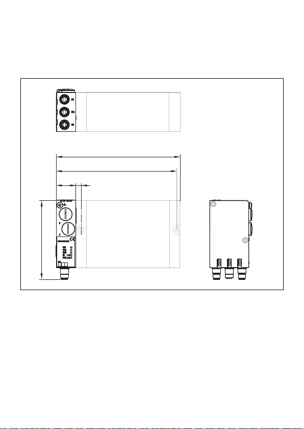
58 AVENTICS | EtherCAT | R412012792–BDL–001–AB
135
A + 33
B + 33
933
Assembly
The dimensions of the complete VS vary according to
module equipment (see Fig. 3).
6.1.1 Dimensions
Fig. 3: Dimensioned drawing of the valve system (bus coupler and valves)
Dimensions A and B depend on the valve block used.
6.2 Labeling the module
Bus coupler O Inscribe the address provided/used for the bus
coupler on the bus coupler in the BTN field.
Slide-in pockets for labels to identify the push-in fittings
are located on the housing (see “Spare parts and
accessories” on page 83).
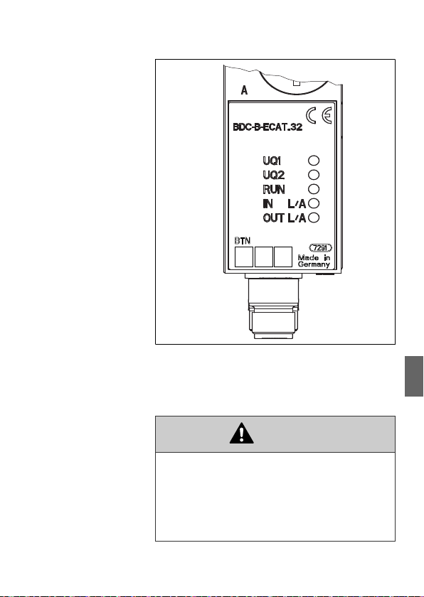
AVENTICS | EtherCAT | R412012792–BDL–001–AB 59
Fig. 4: Label areas on the bus coupler
Assembly
6.3 Connecting the bus coupler
electrically
CAUTION
Applied electric voltage
Danger of injury from electric shock
O Make sure the relevant system component is not
under pressure or connected to power when
electrically connecting modules to the valve
terminal.
English

60 AVENTICS | EtherCAT | R412012792–BDL–001–AB
Assembly
NOTICE
Faulty wiring
Faulty wiring can lead to malfunctions as well as
damage to the bus system.
O Unless otherwise stipulated, comply with the
EtherCAT Technology Group (ETG) construction and
design directives.
O Only use cables that meet the Ethernet
specifications as well as the connection speed and
length requirements.
O In order to assure the protection class, the
shielding, and the required strain relief, the cable
and plug assembly should be done professionally.
NOTICE
Current conduction via differences in potential on the
shield
Compensating currents caused by differences in
potential must not flow through the shield of the
EtherCAT cable, as this will cancel the shielding, which
could damage the line and connected bus coupler.
O If necessary, connect the grounding points for the
system using a separate line.
6.3.1 General notes on connecting the bus
coupler
Use pre-assembled plug connections and cables to
connect the modules.
O Use D-coded M12 plugs for the bus coupler.
O Observe the pin assignment in Tab. 5 if you do not use
pre-assembled plug connections and cables.

AVENTICS | EtherCAT | R412012792–BDL–001–AB 61
2
1
434
3
4
3
5
2
1
5
2
1
5
BUS IN
X71
BUS OUT
X72
X71
X72
X10
1
2
Assembly
Table 5: Assignment X71 (BUS IN) and X72
(BUS OUT), M12, D-coded
Pin Signal Meaning
1 TD+ Transmit pos.
2RD+ Receive pos.
3 TD– Transmit neg.
4RD– Receive neg.
5
Housing Shield or functional grounding
X71/X72: communication connection
The connection technology and plug assignment
comply with the specifications in the technical
directives.
6.3.2 Connecting the bus coupler as an
intermediate station
1. Set up the correct pin assignment (see Tab. 5 on
page 61) on the plug connections if you do not use
pre-assembled cables.
2. Connect the incoming bus connection to the X71
(BUS IN) plug (1).
3. Connect the outgoing bus connection to the X72
(BUS OUT) plug (2).
English
The EtherCAT cable must at least fulfil the
requirements for category CAT5e and should be a
cable with double shielding (S/STP) with a maximum
length of 100 m.
4. Connect the shield on both sides of the bus cable
directly to the plug housing (EMC housing) if non-preassembled cables and plugs with metal housing are
used. This protects data lines from terminal
interference.
Ensure that the plug housing is securely fitted to the
bus coupler housing.
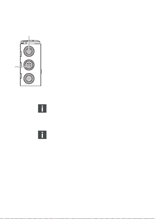
62 AVENTICS | EtherCAT | R412012792–BDL–001–AB
X71
X72
X10
1
2
Assembly
6.3.3 Connecting the bus coupler as a final
station
1. Set up the correct pin assignment (see Tab. 5 on
page 61) on the plug connections if you do not use
pre-assembled cables.
2. Connect the incoming bus connection to the X71
(BUS IN) plug (1).
3. Close the unused socket (2) with an M12 protective
cap to ensure IP protection (see the chapter “Spare
parts and accessories” on page 83).
4. Connect the shield on both sides of the bus cable
directly to the plug housing (EMC housing), if non-preassembled cables and plugs with metal housing are
used. This protects data lines from terminal
interference.
Ensure that the plug housing is securely fitted to the
bus coupler housing.
Equalizing currents:
A potential equalization line of at least 10 mm
needed between the devices to avoid compensating
currents from flowing over the shield of the bus
coupler.
Bus cable:
The EtherCAT cable must at least fulfil the
requirements for category CAT5e and should be a
cable with double shielding (S/STP) with a maximum
length of 100 m.
6.3.4 Connecting the bus coupler logic and load
supply
Power is supplied to the valves and the bus coupler via
the X10 (POWER) plug.
When connecting the logic and load supply of the bus
coupler, ensure pin assignment according to Tab. 6.
2
is
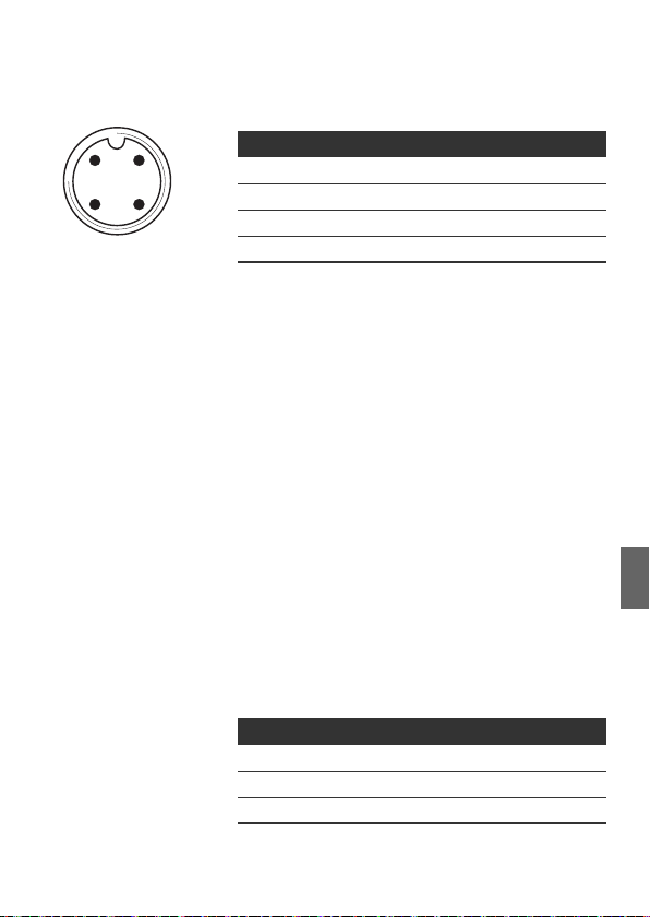
AVENTICS | EtherCAT | R412012792–BDL–001–AB 63
Assembly
2
POWER
X10
Table 6: Assignment of the X10 plug (POWER), M12,
A-coded
Pin X10 Assignment
1
43
1U
Bus coupler logic power supply
L
2UQ1Valve power supply2)
3 OV Ground for U
4UQ2Valve power supply
1)
The power supply (pin 1) must be protected by an external fuse
(500 mA, F).
2)
Both supply voltages (pin 2, pin 4) must each be protected by an
external fuse (3 A, F).
L, UQ1
and U
2).
1)
Q2
W UL, UQ1 and UQ2 are galvanically connected to one
another.
W With the U
switched off byte by byte (each byte represents
and UQ2 valve supplies, the valves can be
Q1
4 double or 8 single solenoid valves).
W The S4 sliding switches are used to assign the valve
groups (8 or 2 valves) (see “Selecting the valve
supply” on page 68). This enables e.g. a separate
switch-off.
The power supply cable must fulfil the following
requirements:
W Cable socket: 4-pin, A-coded without center hole
W Adjust the line cross-section to the total current and
line length: 0.5 mm
2
per wire
English
W Length: Max. 20 m
Table 7: Power consumption on X10 (POWER) on bus
coupler
Signal Assignment Total current
U
L
U
Q1
U
Q2
1)
The total current in the 0 V line may not exceed 4 A.
Logic, inputs Max. 0.5 A
Valves Max. 3 A
Valves Max. 3 A
1)
1)

64 AVENTICS | EtherCAT | R412012792–BDL–001–AB
Assembly
CAUTION
Dangerous voltages
A power pack without safe isolation may lead to
dangerous voltages in the event of a malfunction.
Injuries from electric shock and system damage may
be the consequences.
O Only use a power pack with safe isolation according
to EN 60747, VDE 0551 classification! This ensures
that the electric circuits comply with SELV/PELV
electric circuits in accordance with IEC 60364-4-41.
To connect the bus coupler load supply:
1. Set up the correct pin assignment (see Tab. 6 on
page 63) on the plug connections if you do not use
pre-assembled cables.
2. Connect the bus coupler operating voltages using the
plug connector (see “Spare parts and accessories” on
page 83).
3. Check the operating voltage specifications using the
electrical characteristics and comply with them (see
chapter “Technical data” on page 82).
4. Provide power according to Tab. 7, page 63. Select
the cable cross-section according to the cable length
and occurring currents.
6.3.5 FE connection
Grounding on
the bus coupler
O To discharge EMC interferences, connect the FE
connection (1) on the bus coupler via a lowimpedance line (with low resistance) with the
functional earth (FE).
Recommended cable cross section: 10 mm
2
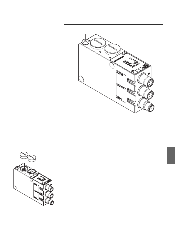
AVENTICS | EtherCAT | R412012792–BDL–001–AB 65
1
A
B
Fig. 5: FE connection on the bus coupler (1)
Commissioning and operation
7 Commissioning and
operation
7.1 Making settings
The following presettings need to be made:
W Selecting the valve supply
W Setting the diagnostic messages
All of these settings are made using the switch beneath
fittings A and B.
Proceed as follows with all presettings:
1. Remove the fitting.
2. Adjust the corresponding setting as described below.
3. Screw the fitting back in (0.6 + 0.2 Nm). Pay attention
that the sealing rings are positioned correctly.
English

66 AVENTICS | EtherCAT | R412012792–BDL–001–AB
S1
S1.1
S1.5
Commissioning and operation
7.1.1 Setting diagnostic messages
The S1 mode switch used to set the diagnostic messages
is located under fitting A.
The system is EtherCAT conform on delivery.
Diagnosis is deactivated (S1.1 set to OFF).
The diagnostic messages are transferred to the
control as General Purpose Inputs (GPI).
O Activate or deactivate the diagnostic messages of the
GPI [10-14] using the switch S1.1.
The modified switch position will only be activated
after a new “power on”.
The queued diagnoses are shown on the LEDs even if the
diagnostic message is turned off.

AVENTICS | EtherCAT | R412012792–BDL–001–AB 67
Commissioning and operation
Table 8: S1, defining the monitoring threshold for valve voltage
Switch/bit Diagnosis Notes
1.1 OFF
1)
: Overload,
valve driver switched off
2)
ON
: Overload,
valve driver switched on
This diagnostic message is
displayed if a valve reports an
overload or short circuit. The
diagnostic message is only
displayed as long as this valve
is actuated.
1.2 OFF1): 12.5 V < UQ1 < 21.6 V/20.4 V
Off
2)
: 12.5 V < UQ1 < 21.6 V/20.4 V
ON
On
1.3 OFF
1)
: 12.5 V < UQ2 < 21.6 V/20.4 V
Off
2)
ON
: 12.5 V < UQ2 < 21.6 V/20.4 V
On
1.4 OFF
1)
: Message UQ1 < 12.5 V
switched off
2)
ON
: Message UQ1 < 12.5 V
In order to ensure safe valve
switching, the switch voltage
must be 20.4 V or 21.6 V!
If the UQ voltage is between
12.5 V and 20.4 V/21.6 V, the
voltage is too low. The low
voltage message appears
approx. 10 ms after being
turned on and approx. 20 ms
after being turned off. If the
voltage is lower than 12.5 V,
this is reported separately.
switched on
1.5 OFF
1)
: Message UQ2 < 12.5 V
switched off
2)
ON
: Message UQ2 < 12.5 V
switched on
1.6 OFF Service switch (default: OFF)
1.7 OFF
1.8 OFF
1)
Deactivated
2)
Activated
1)
: Threshold for UQ1 is 20.4 V The threshold 20.4 V/21.6 V
2)
ON
: Threshold for UQ1 is 21.6 V
1)
: Threshold for UQ2 is 20.4 V
2)
ON
: Threshold for UQ2 is 21.6 V
can be adjusted for different
valve series.
English

68 AVENTICS | EtherCAT | R412012792–BDL–001–AB
4321
DCBA
S2.4
S2 .1
* Switch position
Commissioning and operation
7.1.2 Switching the tolerance level for UQ1 and
valve supply
U
Q2
The monitoring threshold can be switched between
20.4 V and 21.6 V for the various valve series (see Tab. 8
on page 67). On delivery, the threshold is set to 21.6 V
(10%) (S1.7/1.8 set to OFF). If the supply voltage for the
valve control drops below this threshold, a diagnostic
message will be generated.
7.1.3 Selecting the valve supply
The valve power supply can be selected block-wise with
the S2 sliding switch (under fitting B). It is possible to
switch between the U
external supply.
When delivered, all switches are set to position 1.
Q1
NOTICE
Voltage on switches
Switches can be damaged if voltage is applied to them
during operation.
O Always operate switches in a voltage-free state!
and UQ2 voltages from the
O Select the switch position for S2 according to the
following table.

AVENTICS | EtherCAT | R412012792–BDL–001–AB 69
Commissioning and operation
Table 9: S2 switch assignment
Slider Function Switch position 1 Switch position 2
2.1 Power supply control
byte 1
2.2 Power supply control
byte 2
2.3 Power supply control
byte 3
2.4 Power supply control
byte 4
U
(external supply, PIN 2,
Q1
white)
U
(external supply, PIN 2,
Q1
white)
U
(external supply, PIN 2,
Q1
white)
U
(external supply, PIN 2,
Q1
white)
U
(external supply, PIN 4,
Q2
black)
U
(external supply, PIN 4,
Q2
black)
U
(external supply, PIN 4,
Q2
black)
U
(external supply, PIN 4,
Q2
black)
How to assign the valve supply:
1. Open screw cap B (see figure on page 65).
2. Using the S2 sliding switch, assign one of the two
supply voltages U
figure on page 68 and Tab. 9).
or UQ2 to each valve group (see
Q1
English

70 AVENTICS | EtherCAT | R412012792–BDL–001–AB
Commissioning and operation
Examples for assignment of switch S4 and the supply of
assembled valves for 32 valve solenoids can be found in
Tab. 10 and Tab. 11 on pages 71 and 72 (examples 1 to 3/
examples 4 to 6, respectively). The following example
combinations are listed there:
Examples
1)
Subbases used Valve equipment
Example 1 Subbases for double solenoid valves Double solenoid valves
Example 2 Subbases for double solenoid valves Single solenoid valves
Example 3 Subbases for double solenoid valves Single and double solenoid
valves
Example 4 Subbases for single solenoid valves Single solenoid valves
Example 5 Subbases for double solenoid valves Double solenoid valves
combined with
Subbases for single solenoid valves Single solenoid valves
Example 6 Subbases for double solenoid valves Single and double solenoid
valves
combined with
Subbases for single solenoid valves Single solenoid valves
1)
You can also arrange other combinations based on your requirements.
From an electrical connection viewpoint, the
subbases for double solenoid valves must come first
and then those for single solenoid valves. The
maximum number of solenoids for all subbases
is 32.
The assignment of switches and valve supplies
changes if module expansions are used (see
operating instructions R412008961). This also
applies to the following examples in Tab. 10 and
Tab. 11.

AVENTICS | EtherCAT | R412012792–BDL–001–AB 71
Commissioning and operation
Table 10: Examples for assignment of switches and valve supply, 32 valve coils
Example 1 Example 2 Example 3
Subbase for double solenoid valves
Valve
Solenoid
1)
LED
Switches
Byte
position
Address
S2.1 0 A0.0 1 14
Valve
position
Solenoid
1)
LED
Valve
position
1)
Solenoid
LED
1141 14
A0.1 12 – 12
A0.2 2 14
2142 14
A0.3 12 – 12
A0.4 3 14
3143 14
A0.5 12 – 12
A0.6 4 14
4144 14
A0.7 12 – 12
S2.2 1 A1.0 5 14
5145 14
A1.1 12 – 12
A1.2 6 14
614614
A1.3 12 – –
A1.4 7 14
714714
A1.5 12 – –
A1.6 8 14
814814
A1.7 12 – –
S2.3 2 A2.0 9 14
914914
A2.1 12 –
A2.2 10 14
10 14 10 14
A2.3 12 – 12
A2.4 11 14
11 14 11 14
A2.5 12 – 12
A2.6 12 14
12 14 12 14
A2.7 12 – –
English

72 AVENTICS | EtherCAT | R412012792–BDL–001–AB
Commissioning and operation
Table 10: Examples for assignment of switches and valve supply, 32 valve coils
Example 1 Example 2 Example 3
Subbase for double solenoid valves
Valve
Byte
position
Switches
Address
Solenoid
1)
LED
S2.4 3 A3.0 13 14
Valve
position
Solenoid
1)
LED
Valve
position
1)
13 14 13 14
Solenoid
LED
A3.1 12 – –
A3.2 14 14
14 14 14 14
A3.3 12 – 12
A3.4 15 14
15 14 15 14
A3.5 12 – 12
A3.6 16 14
16 14 16 14
A3.7 12 – –
1)
White fields indicate valve positions with double solenoid valves.
Fields highlighted in gray indicate valve positions with single solenoid valves.
Table 11: Examples for assignment of switches and valve supply, 32 valve coils
Example 4 Example 5 Example 6
Byte
Switches
S2.1 0 A0.0
A0.1
A0.2
A0.3
A0.4
A0.5
A0.6
A0.7
Subbase for single
solenoid valves
Valve
Address
position
Solenoid
1)
LED
1141141 14
214 12 12
314214214
414 12 –
514314314
614 12 –
7144144 14
814 12 12
Subbase for single and double solenoid
valves
Valve
position
Solenoid
1)
LED
Valve
position
1)
Solenoid
LED

AVENTICS | EtherCAT | R412012792–BDL–001–AB 73
Commissioning and operation
Table 11: Examples for assignment of switches and valve supply, 32 valve coils
Example 4 Example 5 Example 6
Subbase for single
solenoid valves
Byte
Switches
Address
Valve
position
Solenoid
1)
LED
Subbase for single and double solenoid
valves
Valve
position
Solenoid
1)
LED
Valve
position
1)
Solenoid
LED
S2.2 1 A1.0 9145145 14
A1.1
10 14 614 12
A1.2
11 14 7146 14
A1.3
12 14 814 12
A1.4
13 14 914714
A1.5
14 14 10 14 814
A1.6
15 14 11 14 914
A1.7
16 14 12 14 10 14
S2.3 2 A2.0
S2.4 3 A3.0
1)
White fields indicate valve positions with double solenoid valves.
Fields highlighted in gray indicate valve positions with single solenoid valves.
17 14 13 14 11 14
A2.1
18 14 14 14 12 14
A2.2
19 14 15 14 13 14
A2.3
20 14 16 14 14 14
A2.4
21 14 17 14 15 14
A2.5
22 14 18 14 16 14
A2.6
23 14 19 14 17 14
A2.7
24 14 20 14 18 14
25 14 21 14 19 14
A3.1
26 14 22 14 20 14
A3.2
27 14 23 14 21 14
A3.3
28 14 24 14 22 14
A3.4
29 14 25 14 23 14
A3.5
30 14 26 14 24 14
A3.6
31 14 27 14 25 14
A3.7
32 14 28 14 26 14
English
74 AVENTICS | EtherCAT | R412012792–BDL–001–AB
Commissioning and operation
7.2 Configuring the bus coupler
The configuration steps laid out in this section are
superior to the settings on the bus coupler which have
already been described (see “Making settings” on
page 65) and are a part of the entire system's bus master
configuration.
The work described here may only be carried out by
qualified electronics personnel and in compliance
with the operator's documentation on configuring the
bus master, as well as applicable technical
standards, directives, and safety regulations.
Before starting configuration, the following steps must
have been carried out and completed on the bus coupler:
W You have assembled the bus coupler and valve
terminals (see “Assembly” on page 57).
W You have connected the bus coupler
(see “Connecting the bus coupler electrically” on
page 59).
W You have carried out the presettings
(see “Making settings” on page 65).
NOTICE
Configuration error
An incorrectly configured bus coupler will lead to
malfunctions in the system and may damage the
system.
O The configuration may only be carried out by
qualified electronics personnel!
O Configure the bus system in accordance with your
system requirements, the manufacturer’s
specifications, and all valid technical standards,
directives, and safety regulations. Take the operator’s
documentation on configuring the bus master into
account.
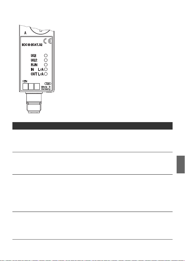
AVENTICS | EtherCAT | R412012792–BDL–001–AB 75
Commissioning and operation
The operating behavior, relevant objects and parameters
to configure the bus coupler, possible setting examples,
and scope of function are listed in the chapter
“Information on the bus master configuration with
EtherCAT” from page 84.
7.3 Testing and diagnosis on the bus
coupler
7.3.1 Reading the diagnostic display on the bus
coupler
The LEDs on the front panel of the bus coupler show the
messages from Tab. 12.
O Before commissioning and during operation,
regularly check bus coupler functions by reading the
diagnostic displays.
Table 12: Definitions for diagnostic LEDs on the bus coupler
LED Signal Description
U
Green Valve supply UQ1 OK
Q1
Red Low voltage (12 V < U
Off Valve supply U
U
Green Valve supply UQ2 OK
Q2
Red Low voltage (12 V < U
Off Valve supply U
RUN Green Operational
Green, flashing Preoperational
Green, occasional flashing Safe operational
Green, flashing quickly Bootstrap
Off INIT
L0/A0 Green, flashing quickly Connection (“link”) and data exchange
(“activity”) with a participant at plug X71
Green Connection (“link”) to a participant at plug X71
Off
No connection (“link”) to a participant at plug X71
< 21.6 V/20.4 V (S3.4))
Q1
< 12 V
Q1
< 21.6 V/20.4 V (S3.4))
Q2
< 12 V
Q2
English

76 AVENTICS | EtherCAT | R412012792–BDL–001–AB
Commissioning and operation
Table 12: Definitions for diagnostic LEDs on the bus coupler
LED Signal Description
L1/A1 Green, flashing quickly Connection (“link”) and data exchange
(“activity”) with a participant at plug X72
Green Connection (“link”) to a participant at plug X72
Off
No connection (“link”) to a participant at plug X72
Table 13: Meaning of the General Purpose Inputs (GPI)
GPI [...] Meaning of the bits
0 Switch S1.2 OPEN/CLOSE
1 Switch S1.3 OPEN/CLOSE
2 Switch S1.4 OPEN/CLOSE
3 Switch S1.5 OPEN/CLOSE
4ONLow voltage (U
OFF Valve supply U
5ONLow voltage (U
OFF Valve supply U
6 ON Valve supply U
OFF Valve supply U
7 ON Valve supply U
OFF Valve supply U
< 21.6 V/20.4 V (S1.7))
Q1
OK
Q1
< 21.6 V/20.4 V (S1.7))
Q2
OK
Q2
< 12 V
Q1
> 12 V
Q1
< 12 V
Q2
> 12 V
Q2
8 Switch S1.1 OPEN/CLOSE
9 ON Short circuit/open loop valve coil
OFF No valve coil diagnostic message
10 ON Switch S1.5 CLOSE
and low voltage (12 V < U
OFF Valve supply U
OK
Q1
< 21.6 V/20.4 V (S1.7))
Q2
11 ON Switch S1.4 CLOSE
and low voltage (12 V < U
OFF Valve supply U
OK
Q1
< 21.6 V/20.4 V (S1.8))
Q2
AVENTICS | EtherCAT | R412012792–BDL–001–AB 77
Table 13: Meaning of the General Purpose Inputs (GPI)
GPI [...] Meaning of the bits
12 ON Switch S1.3 CLOSE
Q1
< 12 V
Q1
> 12 V
and valve supply U
OFF Valve supply U
13 ON Switch S1.2 CLOSE
and valve supply U
OFF Valve supply U
Q2
< 12 V
Q2
> 12 V
14 ON Switch S1.1 CLOSE
and short circuit/open loop valve coil
OFF No valve coil diagnostic message
15 GPO
OFF (default)
[15]
ON service
7.4 Commissioning the bus coupler
Before commissioning the system, the following steps
must have been carried out and completed:
W You have assembled the valve terminal and the bus
coupler (see “Assembling the valve system with the
bus coupler” on page 57).
W You have connected the bus coupler (see “Connecting
the bus coupler electrically” on page 59).
W You have made the settings and configured the
system (see “Making settings” on page 65).
W You have configured the bus master so that it controls
the valves correctly.
Commissioning may only be carried out by qualified
electrical or pneumatic personnel or an instructed
person under the direction and supervision of
qualified personnel
(see “Personnel qualifications” on page 51).
Commissioning and operation
English

78 AVENTICS | EtherCAT | R412012792–BDL–001–AB
Disassembly/exchange
CAUTION
Risk of uncontrolled actuator movements when the
pneumatics are switched on
Danger of injury if the system is in an undefined state
and the manual overrides are set to position “1”.
O Put the system in a defined state before switching it
on.
O Set all manual overrides to position “0”.
O Make sure that no personnel are within the
hazardous zone when the compressed air supply is
switched on.
O Also observe the applicable instructions and safety
information in the VS operating instructions.
1. Switch on the operating voltage.
2. Check the LED displays on all modules.
3. Switch on the compressed air supply.
8 Disassembly/exchange
You can exchange the bus coupler, if needed.
The AVENTICS warranty only applies to the delivered
configuration and extensions taken into account in
the configuration. The warranty no longer applies
after a conversion that exceeds these extensions.
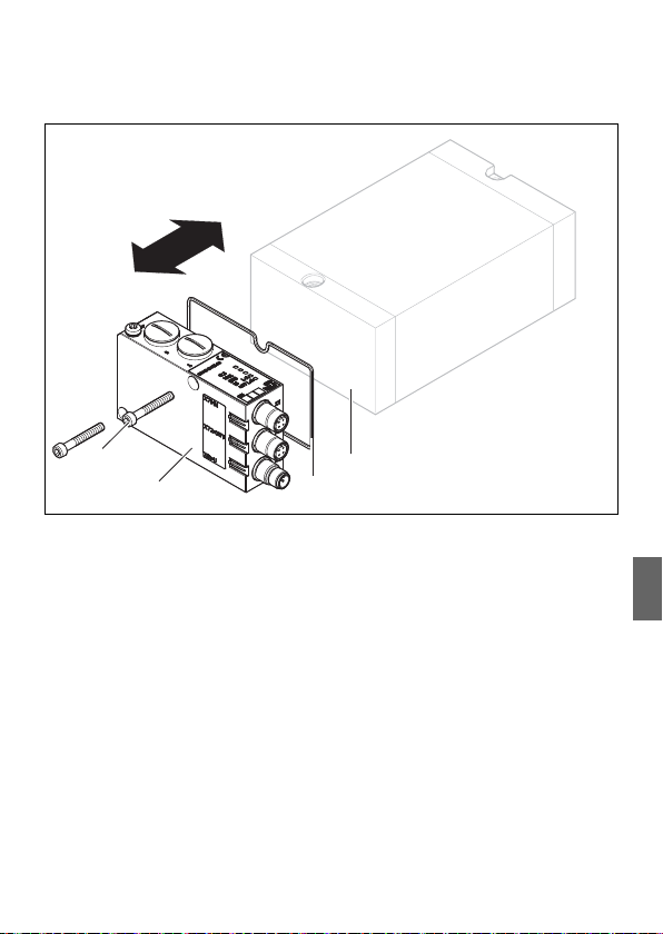
AVENTICS | EtherCAT | R412012792–BDL–001–AB 79
1
2
3
4
8.1 Exchanging the bus coupler
Fig. 6: Exchanging the bus coupler, example
1 Hexagonal socket-head screws M4x35
2 Bus coupler
3 Seal
4 VS EP end plate
Disassembly/exchange
English

80 AVENTICS | EtherCAT | R412012792–BDL–001–AB
Disassembly/exchange
CAUTION
Applied electric voltage and high pressure!
Danger of injury from electric shocks and sudden
pressure drops.
O Turn off the operating voltage and compressed air
supply.
O Observe the stipulated precautionary measures
when working with ESD-sensitive assemblies.
To exchange the bus coupler:
1. Disconnect the electrical connections from the bus
coupler (2).
2. Loosen the bus coupler (2) (2 hexagon socket head
screws DIN 912 – M4 (1), wrench size 4).
3. Remove the bus coupler (2) from the EP end plate (4).
4. Push the new bus coupler (2) onto the EP end
plate (4).
5. Make sure that seal (3) is fitted correctly.
6. Screw down the bus coupler (2) (2 hexagon socket
head screws DIN 912 – M4 (1) each, wrench size 4).
Tightening torque 3.0 + 0.5 Nm.
7. Make all the presettings on the new bus coupler (2)
(see “Making settings” on page 65).
8. Re-establish the electric connections.
9. Check the configuration and adjust it if necessary
(see “Configuring the bus coupler” on page 74).

AVENTICS | EtherCAT | R412012792–BDL–001–AB 81
Service and maintenance
9 Service and maintenance
CAUTION
Applied electric voltage and high pressure!
Danger of injury from electric shocks and sudden
pressure drops.
O Make sure the system is not pressurized or
connected to power before carrying out any service
or maintenance work.
9.1 Servicing the modules
NOTICE
Damage to the surface caused by solvents and
aggressive detergents!
The surfaces and seals could be damaged by
aggressive solvents and cleaning agents.
O Never use solvents or aggressive detergents.
O Regularly clean the device with a damp cloth. Only
use water or a mild cleaning agent.
9.2 Maintaining the bus coupler
The bus coupler is maintenance-free.
O Comply with the maintenance intervals and
specifications for the entire system.
English

82 AVENTICS | EtherCAT | R412012792–BDL–001–AB
Technical data
10 Technical data
10.1 Characteristics
General
Protection class according
to EN 60529/IEC 529 IP65 when assembled
Ambient temperature
W Operation
W Storage
Electromagnetic compatibility
Interference immunity EN 61000-6-2
Interference emission EN 61000-6-4
Electrical
Operating voltage
W Logic
–U
L
–I
L
–Fuse protection for logic voltage 500 mAF
W Load U
Line length for power supply Max. 20 m
Maximum current in the 0 V line 4 A
Internal voltage drop 0.6 V DC
Max. output current per valve output 100 mA
Number of outputs 32
No. of output bytes Fixed, output 4 bytes and input 0 bytes
Start-up time Approx. 2 s
, U
Q1
–Fuse protection for the power supply 3.0 AF each
U
0°C to +50°C, without condensation
–20°C to +70°C
10.2 Bus coupler
24 V DC (+20%/-15%)
100 mA
Q2
24 V DC (10%/15%)
Protective extra-low voltage
(SELV/PELV)
according to EC 364-4-41,
residual ripple 0.5%

AVENTICS | EtherCAT | R412012792–BDL–001–AB 83
Spare parts and accessories
11 Spare parts and
accessories
11.1 Bus coupler
Order number
Bus coupler with fieldbus protocol EtherCAT with control for
32 valve solenoids
Accessories
Set: Seal, 2 screws M4, 1 screw FE R412008885
10x metric blanking screws R412008886
5x slide-in card labels R412008887
M12x1 protective cap 1823312001
1)
Delivery incl. 2 hexagon socket head screws, seal and manual
1)
R412009573
11.2 Power plug for bus coupler
Order number
Plug connector for power supply,
M12x1 coupling, 4-pin for cable Ø 4–8 mm,
A-coded
180° (X10, POWER) 8941054324
90° (X10, POWER) 8941054424
12 Disposal
Dispose of the device in accordance with the currently
applicable regulations in your country.
English

84 AVENTICS | EtherCAT | R412012792–BDL–001–AB
Appendix
13 Appendix
13.1 Information on the bus master
configuration with EtherCAT
The bus coupler is an output module with 32 permanently
set digital outputs. As a result, very few steps are
required for configuration and administration.
13.2 Operating behavior
4 bytes of master real-time data (outputs) can be
processed per switch. In addition, diagnostic data is
transferred as General Purpose Inputs (GPIs). The data
length of the GPIs and GPOs is 2 bytes (16 bits) each.
The bus coupler does not have any distributed clock (DC)
capabilities.
Behavior after poweronThe hardware components are tested (start-up test) after
13.3 Start-up behavior
the module is switched on (connection of the 24 V logic
supply).
If the start-up test has been successfully completed and
bus voltage is available, the bus coupler is initialized
according to the presettings on the rotary and DIP
switches.
After successful initialization, the module is in INIT mode
until the master establishes communication. It can now
be switched by the EtherCAT control into the various
modes until it is “operational”.
13.4 Configuration file
The file is an ASCII file in Extensible Markup Language
format (XML) specified by the EtherCAT Technology Group
(ETG) that describes the objects/performance data for an
EtherCAT device. This file is available under the file name
BDC_ECAT32.XML for the bus coupler.
The file can be downloaded from the Internet at
www.aventics.com/mediadirectory.

14 Index
AVENTICS | EtherCAT | R412012792–BDL–001–AB 85
Index
W A
Abbreviations 49
Accessories 83
Assembly
Assembly options 57
FE connection 64
W B
Bus coupler
Commissioning 77, 78
Construction 56
Exchange 79
Spare parts, Accessories 83
Technical data 82
Testing and diagnosis 75
Bus master configuration 84
W C
Characteristics 82
Commissioning
Commissioning 77
Diagnostic display 75
Presettings 65
Components
Bus coupler 56
Configuration file 84
Configuration, bus master 84
W D
Diagnostic display, bus coupler 75
Diagnostics
Setting 66
Disposal 83
W E
Electrical connection
Bus coupler as final station 62
Bus coupler as intermediate
station 61
FE 64
Logic and load supply 62
Shielding 61
W L
Labelling
Module 58
W M
Mode switch 66
W N
Notes on Safety
Cleaning 53
General 51
W O
Operating behavior, bus
connection 84
W P
Plug connections
X10 (POWER) 62
Presettings
Diagnostics 66
Setting diagnostic messages 67
Setting the baud rate 66
W Q
Qualifications, personnel 51
English

86 AVENTICS | EtherCAT | R412012792–BDL–001–AB
Index
W S
Safety instructions, definitions 48
Selecting the valve supply 68
Setting the baud rate 66
Spare Parts 83
Standards 53
Switch
S2 68
W T
Test and diagnosis
Bus coupler 75
W U
Use
Improper 50
Intended 50

AVENTICS | EtherCAT | R412012792–BDL–001–AB 87
Sommaire
Sommaire
1 A propos de cette documentation ................ 89
1.1 Validité de la documentation...............................89
1.2 Documentations nécessaires et
complémentaires....................................................89
1.3 Présentation des informations ........................... 89
1.3.1 Consignes de sécurité ......................................... 90
1.3.2 Symboles ................................................................ 90
1.3.3 Abréviations ........................................................... 91
2 Consignes de sécurité .................................. 92
2.1 A propos de ce chapitre........................................92
2.2 Utilisation conforme ..............................................92
2.3 Utilisation non conforme......................................93
2.4 Qualification du personnel...................................93
2.5 Consignes générales de sécurité....................... 94
2.6 Consignes de sécurité selon le produit
et la technique.........................................................95
3 Domaines d’application ................................ 96
4 Fourniture ...................................................... 97
5 Description de l’appareil .............................. 97
5.1 Vue d’ensemble du système de distributeurs ..98
5.2 Composants..............................................................99
5.2.1 Coupleur de bus .................................................... 99
6 Montage ........................................................ 101
6.1 Montage du coupleur de bus
sur le système de distributeurs.......................101
6.1.1 Dimensions .......................................................... 101
6.2 Marquage des modules ......................................102
6.3 Raccordement électrique du coupleur de bus103
6.3.1 Remarques générales concernant le
raccordement du coupleur de bus ............... 104
6.3.2 Raccorder le coupleur de bus en tant
que station intermédiaire ................................ 105
6.3.3 Raccordement du coupleur de bus en tant
que dernière station ......................................... 105
6.3.4 Raccordement de l’alimentation
des circuits logiques et des distributeurs
du coupleur de bus ........................................... 106
6.3.5 Raccord FE .......................................................... 108
Français

88 AVENTICS | EtherCAT | R412012792–BDL–001–AB
Sommaire
7 Mise en service et utilisation ..................... 109
7.1 Effectuer les paramétrages préalables .........109
7.1.1 Réglage des notifications de diagnostic ..... 109
7.1.2 Commuter le niveau de tolérance de
l’alimentation des distributeurs U
7.1.3 Sélectionner l’alimentation des distributeurs 111
7.2 Configuration du coupleur de bus...................116
7.3 Test et diagnostic du coupleur de bus...........118
7.3.1 Lecture de l’affichage de diagnostics
sur le coupleur de bus ..................................... 118
7.4 Mise en service du coupleur de bus ...............120
8 Démontage et remplacement .................... 121
8.1 Remplacer le coupleur de bus..........................121
9 Nettoyage et entretien ................................ 123
9.1 Entretien des modules........................................123
9.2 Maintenance du coupleur de bus.....................123
10 Données techniques .................................... 124
10.1 Caractéristiques....................................................124
10.2 Coupleur de bus....................................................124
11 Pièces de rechange et accessoires ........... 125
11.1 Coupleur de bus....................................................125
11.2 Connecteur pour coupleur de bus...................125
12 Elimination des déchets ............................. 125
13 Annexe .......................................................... 126
13.1 Indications concernant la configuration
du maître bus avec EtherCAT ...........................126
13.2 Comportement en service..................................126
13.3 Comportement de mise en route.....................126
13.4 Fichier de configuration......................................126
14 Index ............................................................. 128
et U
111
Q1
Q2

AVENTICS | EtherCAT | R412012792–BDL–001–AB 89
A propos de cette documentation
1 A propos de cette
documentation
1.1 Validité de la documentation
Cette documentation contient des informations
importantes pour installer, utiliser et e ntretenir le produit
de manière sûre et conforme, ainsi que pour pouvoir
éliminer soi-même de simples interférences.
O Lire entièrement cette documentation et en
particulier le chapitre « Consignes de sécurité » avant
de travailler avec le produit.
1.2 Documentations nécessaires et
complémentaires
O Ne mettre le produit en service qu’en possession des
documentations suivantes et qu’après les avoir
comprises et observées :
Tableau 1 : Documentations nécessaires et complémentaires
Désignation Numéro du document Type de document
Documentation du système de
distributeurs HF03-LG
Documentation du système de
distributeurs HF04 D-SUB
Documentation d’installation
R412008233 Instructions
R412015493 Instructions
Pour de plus amples informations concernant les
composants, consulter le catalogue de produits en ligne
d’AVENTICS sur le site
www.aventics.com/pneumatics-catalog.
1.3 Présentation des informations
Afin de pouvoir travailler rapidement et en toute sécurité
avec ce produit, cette documentation contient des
consignes de sécurité, symboles, termes et abréviations
standardisés. Ces derniers sont expliqués dans les
paragraphes suivants.
Français
90 AVENTICS | EtherCAT | R412012792–BDL–001–AB
A propos de cette documentation
1.3.1 Consignes de sécurité
Dans la présente documentation, des consignes de
sécurité figurent devant les instructions dont l’exécution
recèle un risque de dommages corporels ou matériels.
Les mesures décrites pour éviter des dangers doivent
être respectées.
Les consignes de sécurité sont structurées comme suit :
MOT-CLE
Type et source de danger
Conséquences en cas de non-respect
O Mesure préventive contre le danger
W Signe d’alerte : attire l’attention sur un danger
W Mot clé : précise la gravité du danger
W Type et source de danger : désigne le type et la
source du danger
W Conséquences : décrit les conséquences en cas de
non-respect
W Remède : indique comment contourner le danger
Tableau 2 : Classes de dangers selon la norme ANSI Z535.6-2006
Signal de danger, mot-clé Signification
Signale une situation dangereuse susceptible
ATTENTION
REMARQUE
d’entraîner des blessures légères à modérées si le
danger n’est pas évité.
Dommages matériels : le produit ou son
environnement peuvent être endommagés.
1.3.2 Symboles
Les symboles suivants signalent des consignes qui ne
relèvent pas de la sécurité mais améliorent néanmoins
l’intelligibilité de la documentation.

AVENTICS | EtherCAT | R412012792–BDL–001–AB 91
Tableau 3 : Signification des symboles
Symbole Signification
En cas de non-respect de cette
information, le produit ne livrera pas sa
performance optimale.
O Action isolée et indépendante
1.
2.
3.
Consignes numérotées :
Les chiffres indiquent l’ordre des
différentes actions.
A propos de cette documentation
1.3.3 Abréviations
Cette documentation emploie les abréviations suivantes :
Tableau 4 : Abréviations
Abréviation Signification
BTN Numéro d’usager du bus
CAT5e Câble de transmission de (catégorie 5e)
FE Mise à la terre
CEM Compatibilité électromagnétique
Embase terminale EP
ESD Décharge électrostatique
ETG EtherCAT Technology Group
GPI General Purpose Input
GPIO General Purpose Input Output
GPO General Purpose Output
INIT Mode Mode initialisation
Embase terminale P Embase terminale avec raccordements pneumatiques
SELV/PELV Basse tension de sécurité
S/STP Screened/Shielded Twisted Pair
UDP/IP User Datagram Protocol/Internet Protocol
VS Système de distributeurs
Embase terminale avec raccords électriques et pneumatiques
Français

92 AVENTICS | EtherCAT | R412012792–BDL–001–AB
Consignes de sécurité
2 Consignes de sécurité
2.1 A propos de ce chapitre
Le produit a été fabriqué selon les règles techniques
généralement reconnues. Des dommages matériels et
corporels peuvent néanmoins survenir si ce chapitre de
même que les consignes de sécurité ne sont pas
respectés.
O Lire la présente documentation attentivement et
complètement avant d’utiliser le produit.
O Conserver cette documentation de sorte que tous les
utilisateurs puissent y accéder à tout moment.
O Toujours transmettre le produit à de tierces
personnes accompagné des documentations
nécessaires.
2.2 Utilisation conforme
Ce produit est un composant d’installation
électropneumatique.
Le produit peut être utilisé comme suit :
W Uniquement dans le domaine industriel.
W Dans le respect des limites de puissance indiquées
dans les données techniques.
Le produit est destiné à un usage dans le domaine
professionnel et non privé.
L’utilisation conforme inclut le fait d’avoir lu et compris
cette documentation dans son intégralité et en particulier
le chapitre « Consignes de sécurité ».

AVENTICS | EtherCAT | R412012792–BDL–001–AB 93
Consignes de sécurité
2.3 Utilisation non conforme
Toute autre utilisation que celle décrite au chapitre
« Utilisation conforme » est non conforme et par
conséquent interdite.
En cas de pose ou d’utilisation de produits inadapt és dans
des applications qui relèvent de la sécurité, des états
d’exploitation incontrôlés peuvent survenir dans ces
applications et entraîner des dommages corporels et/ou
matériels. Par conséquent, utiliser des produits dans des
applications qui relèvent de la sécurité uniquement
lorsque ces applications sont expressément spécifiées et
autorisées dans la documentation. Par exemple, dans les
zones de protection contre les explosions ou dans les
pièces de sécurité d’une commande (sécurité
fonctionnelle).
AVENTICS GmbH décline toute responsabilité en cas de
dommages résultant d’une utilisation non conforme.
Toute utilisation non conforme est aux risques et périls de
l’utilisateur.
Une utilisation non conforme du coupleur de bus
correspond :
W à une utilisation en dehors des domaines
d’application cités dans ce mode d’emploi.
W à une utilisation déviant des conditions de
fonctionnement décrites dans ce mode d’emploi.
2.4 Qualification du personnel
Les opérations décrites dans cette documentation
exigent des connaissances électriques et pneumatiques
de base, ainsi que la connaissance des termes techniques
qui y sont liés. Afin d’assurer une utilisation en toute
sécurité, ces travaux ne doivent par conséquent être
effectués que par des professionnels spécialement
formés ou par une personne instruite et sous la direction
d’un spécialiste.
Une personne spécialisée est capable de juger des
travaux qui lui sont confiés, de reconnaître d’éventuels
dangers et de prendre les mesures de sécurité adéquates
grâce à sa formation spécialisée, ses connaissances et
expériences, ainsi qu’à ses connaissances des directives
correspondantes. Elle doit respecter les règles
spécifiques correspondantes.
Français

94 AVENTICS | EtherCAT | R412012792–BDL–001–AB
Consignes de sécurité
2.5 Consignes générales de sécurité
W Respecter les consignes de prévention d’accidents et
de protection de l’environnement applicables.
W Respecter les prescriptions et dispositions de
sécurité en vigueur dans le pays d’utilisation /
d’application du produit.
W Utiliser les produits AVENTICS exclusivement lorsque
leur état technique est irréprochable.
W Respecter toutes les consignes concernant le produit.
W Les personnes montant, commandant, démontant ou
entretenant des produits AVENTICS, ne doivent pas
être sous l’emprise d’alcool, de drogues ou de
médicaments divers pouvant altérer leur temps de
réaction.
W Utiliser exclusivement les accessoires et pièces de
rechange agréés par le constructeur afin de ne pas
mettre en danger les personnes du fait de pièces de
rechange non appropriées.
W Respecter les données techniques ainsi que les
conditions ambiantes spécifiées dans la
documentation du produit.
W En cas de pose ou d’utilisation de produits
inappropriés dans des applications qui relèvent de la
sécurité, des états de fonctionnement incontrôlés
peuvent survenir dans ces applications et entraîner
des dommages corporels et/ou matériels. Par
conséquent, utiliser des produits dans des
applications qui relèvent de la sécurité uniquement
lorsque ces applications sont expressément
spécifiées et autorisées dans la documentation.
W Il n’est admis de mettre le produit en service que
lorsqu’il a été constaté que le produit final
(par exemple une machine ou une installation) dans
lequel les produits AVENTICS sont utilisés satisfait
bien aux dispositions du pays d’utilisation,
prescriptions de sécurité et normes de l’application.

AVENTICS | EtherCAT | R412012792–BDL–001–AB 95
Consignes de sécurité
2.6 Consignes de sécurité selon le
produit et la technique
W En règle générale ne pas modifier ni transformer
l’appareil.
W Utiliser l’appareil uniquement dans le champ de
travail indiqué dans les données techniques.
W Ne surcharger en aucun cas l’appareil de manière
mécanique. Ne jamais y déposer d’objets.
W
Utiliser cet appareil uniquement dans le domaine
industriel (classe A). Pour les installations devant être
utilisées dans les espaces de séjour (habitations,
bureaux et sites de production), demander une
autorisation individuelle auprès d’une administration
ou d’un office de contrôle. En Allemagne, de telles
régulations sont délivrées par la Regulierungsbehörde
für Telekommunikation und Post (administration de
régulation des Postes et Télécommunications, RegTP).
W S’assurer que l’alimentation en tension se situe dans
la plage de tolérance indiquée pour les modules.
W Respecter les consignes de sécurité reprises dans le
mode d’emploi du système de distributeurs.
W Tous les composants sont alimentés par un bloc
d’alimentation à 24 V. Le bloc d’alimentation doit être
équipé d’une mise hors service de sécurité
conformément à la norme EN 60742, classification
VDE 0551. Les composants de circuit correspondants
sont donc valables en tant que composants de circuit
SELV/PELV selon IEC 60364-4-41.
W Débrancher la tension de service avant de brancher
Lors du montage W Toujours mettre la partie concernée de l’installation
ou débrancher des connecteurs.
hors tension et hors pression avant de monter
l’appareil ou de le démonter. Veiller à protéger
l’installation contre une remise en marche pendant
les travaux de montage.
W Mettre les modules et le système de distributeurs à la
terre. Lors de l’installation du système, respecter les
normes suivantes :
– DIN EN 50178, classification VDE 0160
– VDE 0100
Français

96 AVENTICS | EtherCAT | R412012792–BDL–001–AB
Domaines d’application
Lors de la
mise en service
Lors du
fonctionnement
Lors du nettoyage W Ne jamais utiliser de solvants ni de détergents
W L’installation ne doit avoir lieu qu’en l’absence de
toute tension et de toute pression et n’être effectuée
que par du personnel qualifié et expérimenté.
N’effectuer la mise en service électrique qu’en
l’absence de toute pression afin d’éviter tout
mouvement dangereux des actionneurs.
W Ne mettre le système en service que lorsqu’il est
complètement monté, correctement câblé et
configuré, et après l’avoir testé.
W L’appareil est soumis à l’indice de protection IP 65.
Avant la mise en service, s’assurer que tous les joints
et bouchons des raccords enfichables soient
étanches, afin d’éviter que des liquides et des corps
solides puissent pénétrer dans l’appareil.
W Assurer une aération ou un refroidissement suffisant
lorsque le système de distributeurs présente les
caractéristiques suivantes :
– équipement complet
– sollicitation continue des bobines
agressifs. Nettoyer l’appareil uniquement avec un
chiffon légèrement humide. Pour cela, utiliser
exclusivement de l’eau et éventuellement un
détergent doux.
3 Domaines d’application
Le coupleur de bus sert à la commande électrique des
distributeurs via la technologie Ethernet EtherCAT en
temps réel.
Il est exclusivement prévu pour fonctionner en tant
qu’esclave dans une ligne EtherCAT selon IEC 61158/
61784.

AVENTICS | EtherCAT | R412012792–BDL–001–AB 97
Fourniture
4 Fourniture
La fourniture d’un système de distributeurs configuré
comprend :
W 1 système de distributeurs conformément à la
configuration et à la commande
W 1 mode d’emploi du système de distributeurs
W 1 mode d’emploi du coupleur de bus
La fourniture d’un jeu de pièces pour un coupleur de bus
comprend :
W 1 coupleur de bus avec joint et 2 vis de fixation
W 1 mode d’emploi du coupleur de bus
Le VS est configuré individuellement. La
configuration exacte peut être affichée à l’aide du
numéro de référence dans le configurateur Internet
d’AVENTICS.
5 Description de l’appareil
Le coupleur de bus permet de commander le VS par le
biais de la technologie Ethernet EtherCAT en temps réel.
Outre le raccord des lignes de données et des
alimentations en tension, le coupleur de bus permet le
réglage de différents paramètres ainsi que le diagnostic
par le biais de LED. Pour une description plus détaillée du
coupleur de bus, consulter le chapitre « Composants » à
la page 99.
La vue d’ensemble suivante offre un aperçu du système
de distributeurs et de ses composants. Le VS lui-même
est décrit dans un propre mode d’emploi.
Français

98 AVENTICS | EtherCAT | R412012792–BDL–001–AB
Description de l’appareil
5.1 Vue d’ensemble du système de
distributeurs
Selon la commande, le système de distributeurs est
constitué des composants représentés à la fig. 1 :
3
2
1
4
Fig. 1 : Vue d’ensemble : exemple de configuration de coupleur de bus avec VS monté
1 Coupleur de bus, type design B
2 Embase terminale EP VS
3 Porte-distributeurs
4 Raccord FE
1)
Avec mode d’emploi propre
1)

AVENTICS | EtherCAT | R412012792–BDL–001–AB 99
2
1
3
7
4
5
6
8
9
9
Description de l’appareil
5.2 Composants
5.2.1 Coupleur de bus
Fig. 2 : Vue d’ensemble du coupleur de bus
1 Affichages LED pour notifications de diagnostic
2 Case d’inscription BTN
3 Raccord X71 (BUS IN) pour le coupleur de bus pour la commande des distributeurs
4 Raccord X72 (BUS OUT) pour le coupleur de bus
5 Raccord X10 (POWER) pour l’alimentation en tension du système électro nique et des
bobines de distributeur
6 Capuchon de protection A : commutateur DIP S1 (réglages pour diagnostic)
7 Capuchon de protection B : commutateur à coulisse S2
(assignation des distributeurs et tension d’alimentation)
8 Raccord FE
9 Poche pour les étiquettes à insérer (voir « Pièces de rechange et accessoires »
à la page 125)
1)
Pour l’affectation des connecteurs, voir page 104 et 106
1)
1)
Français

100 AVENTICS | EtherCAT | R412012792–BDL–001–AB
Description de l’appareil
Le coupleur de bus est exclusivement destiné au
fonctionnement en tant que participant d’un segment bus
Adresse EtherCAT Aucun interrupteur n’est prévu pour le réglage de
Débit de transmission Le débit de transmission s’élève à 100 MBits/s duplex
Diagnostic Les tensions d’alimentation pour les circuits logiques et
Nombre de
distributeurs pouvant
être commandés
EtherCAT Pour toutes les consignes et directives EtherCAT, se
Certification L’appareil est certifié selon les directives de l’ETG.
EtherCAT.
l’adresse EtherCAT.
Le coupleur de bus reconnaît l’attribution automatique de
l’adresse EtherCAT.
intégral.
la commande des distributeurs sont surveillés. Si les
limites des alimentations du distributeur ne sont pas
atteintes, un signal de diagnostic est alors généré et
signalé grâce à une LED de diagnostic et à l’information
de diagnostic.
Le coupleur de bus dispose de 32 sorties de distributeur.
Le nombre maximum de bobines pouvant être
commandées est ainsi limité.
16 distributeurs bistables ou 32 distributeurs
monostables peuvent être pilotés de cette manière. Une
combinaison des distributeurs est également possible.
reporter aux spécifications de l’EtherCAT Technology
Group (ETG).
Le coupleur de bus reconnaît la version EtherCAT 2.2.0.0.
L’utilisation de switches ou de routeurs dans un réseau
EtherCAT est autorisée. EtherCAT reconnaît Broadcast,
Multicast et assiste la communication transversale entre
esclaves. Des datagrammes UDP / IP sont également
possibles.
Le coupleur de bus possède deux raccords Ethernet
Twisted Pair selon 802.3u.
 Loading...