

Page 1
Product Overview
Engineering Information
Screws
Ball and roller screws are key components to build electric actuators. They transfer rotary movements of the motor into linear movements. Their
efficiency and their load and speed capabilities have a very big influence on the performance of electric actuators.
Emerson builds AVENTICS electric actuators with precision screw solutions that fulfill the most demanding applications in terms of efficiency, precision,
durability and value. All screws are made of high-strength materials with specific heat-treatment.
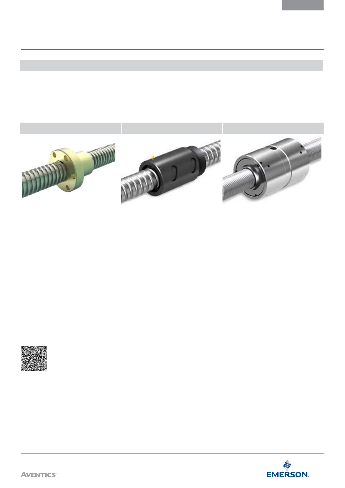
Lead Screw Precision Rolled Ball Screws Roller Screws
Introduction
These screws transmit torque into linear motion
through direct sliding friction.
A typical assembly consists of a steel screw and
plastic nut. Some of the electric actuators are
equipped with lead screws with a relatively high
friction coefficient that makes them well suited
for self-locking application.
Lead screw actuators accommodate high static
force, withstand excessive vibration, operate
quietly, and represent cost-effective solutions.
Catalog Pages
To select a series SPRA actuator, click
here
Ball screw assemblies provide high performance
solutions suitable for a wide range of
applications where high loads, precision driving,
durability and value are prerequisites.
Standard lead precision is G9, according to ISO
286-2:1988. Production meets G7 lead precision
for screw shaft nominal diameter starting from
20 mm. On request, Emerson can deliver ball
screws with G5 lead precision, according to ISO
3408-3:2006, defined for positioning screws,
and matching the lead precision of G5 ground
ball screws.
Roller screws offer a performance level far
beyond the capabilities of ball screws. Planetary
roller screws are well suited for heavy loads,
high duty, high rotational speed, high linear
speed, high acceleration and rigidity, and for
operation in harsh environments.
For very high precision applications,
recirculating roller screws with a very fine lead
of thread allow high positioning accuracy,
repeatability and exceptional rigidity.
or scan the QR code below to get to the catalog pages.
Visit our website at Emerson.com/AVENTICS
1
Page 2

Product Overview
Introduction
Engineering Information
The AVENTICS MotionFinder is a free online actuator and accessory selection tool. This calculation tool will give
recommendations to select components of a linear servo axis (motor, linear unit and accessories) based on the
application data. Based on the requirements and operating conditions of the user, the program will transform them
into performance requirements.
The user can insert the main information about the working cycle, describing each step as absolute movement,
weight and inertia of the mass to be moved. Based on that, the program will provide simple graphs that show the
required position, speed and acceleration over time.
Consequently, the program suggests a list of possible solutions that fulfill the user needs in terms of perfomance
and lifetime. For each solution, the graphs are updated to show the requirements vs. the real performance of the
selection.
2
Visit our website at Emerson.com/AVENTICS
Page 3

Engineering Information
Simplified Calculation Process
Calculation
By following the described flow (diagram 1), the user can
select the right linear unit and motor that fulfill the
application needs. Each of these steps is described in the
following pages, with the related calculation formulas to be
used and a real example. The main factors to be considered
from the application are the equivalent dynamic axial load,
acting on the actuator, the travel distance to be achieved
and the desired speed during the working cycles.
Diagram 1
Calculate the equivalent
dynamic axial load
of the application F
Calculate the service
life distance L
the actuator
10dist
m
of
From these values, user can then define the right actuator
size and the required motor performances, in terms of
torque and rotating speed. Finally, it’s then possible to
define the desired type of motor adapters, to match the
possible dimensional constrains or to get a reduction ratio
between the motor and the linear unit. If further assistance
is needed, please contact Emerson to get complete
technical support.
Draw the point L
on the lifetime graph.
Start with the smallest
linear unit size
Is the point under
the curve?
Make a gearbox
and motor selection
10dist
; Fm
Repeat the step with the
next bigger linear unit size
Visit our website at Emerson.com/AVENTICS
3
Page 4

3
General Calculation Formula
Load
Load
Calculation
How to Calculate the
Equivalent Dynamic Axial
Load Fm of the Application.
Engineering Information
In most of the applications, the magnitude of the load
fluctuates over the travelling distance. The service life of
the linear unit depends on the load acting on it. To simplify
the calculation we calculate the equivalent dynamic axial
load over a full motion cycle Fm which has the same
influence on the linear unit’s service life as the actual
fluctuating load.
3
3
F
x s1 + F
Fm= = 570 N
1
F
1
S
1
S
F
2
2
3
x s2 + F
2
s
+ s2 + s
1
3
3
3
F
3
S
3
x s3 + ...
Stroke
or
Example to calculate the equivalent dynamic axial
load
F1 = 700 N, s1 = 200 mm
F2 = 500 N, s2 = 0 mm
F3 = 300 N, s3 = 200 mm
3
Fm= = 570 N
7003 x 200 + 5003 x 0 + 3003 x 200
200 + 0 + 200
or
300 + 1 400
Fm=
3
= 566 N
F
Fm=
min
+ 2F
max
where:
F
max
F
min
Stroke
Fm: Equivalent dynamic axial load in N
F1, F2… Fn: Load exerted over a segment of travelled
distance sn
S1, S2… Sn: Travelling distance over which the load Fn
is exerted
4
Visit our website at Emerson.com/AVENTICS
Page 5

Fm [N]
Engineering Information
How to Calculate the
Lifetime Distance L
10dist
General Calculation Formula
Calculation
The service life distance L
is defined as the life in km
10di st
that 90% of a sufficiently large group of apparently identical
actuators can be expected to attain or exceed.
x 3,6
S
=
= s
cycle ncycles
cycle tL
t
cycle
L
10di st
L
10dist
where:
L
: Lifetime distance in km
10di st
S
: Distance travelled per motion cycle in m
cycle
(both directions)
t
: Time per motion cycle in s
cycle
(from one motion cycle to the next)
tL: Required lifetime in hours
n
: Number of cycles (in 1000)
cycles
Example to select a linear unit
Select the linear unit
Equivalent dynamic axial load Fm = 570 N
Lifetime distance L
2 200
2 000
1 800
1 600
1 400
1 200
1 000
800
600
400
200
0
0 2 000 4 000 6 000 8 000 10 000
SPRA-BN-040
CASM–40–BN CASM–40–BS
= 1987 km
10di st
Operating point below
SPRA-BN-040
the CASM-40-BN curve
Expected service life
L
10dist
SPRA-BS-040
Lifetime [km]
Total distance travelled per motion cycle: s
Total time per motion cycle: t
cycle
= 20 s
= 0,4 m
cycle
Required lifetime: tL = 5 years × 230 days/year × 24 hours/
day = 27600 hours
n
= 3 cycles/minute × 60 minutes × 24 hours × 230 days
cycles
× 5 years / 1000 = 4968 k
0,4 x 27 000 x 3,6
= = 1 987 km
10dist
20
= 0,4 × 4968 = 1987 km
L
10di st
L
cycles
The operating point is below the SPRA-BN-040 curve. It is
the smallest linear unit which fulfills the requirements. The
expected service life is almost 6500 km.
Visit our website at Emerson.com/AVENTICS
5
Page 6

Motor Selection
Load
Calculation
How to Calculate the
Thermal Load of the Motor F
Engineering Information
th
To calculate the mean motor torque, we first need to
calculate the thermal load Fth over the motor running time.
Please note that the use of a motor brake during pause
time will reduce the needed power of the motor.
2
Fth=
2
F
1
x t1 + F
2
x t2 + F
2
t
+ t2 + t
1
2
3
3
x t3
Fth: Equivalent thermal load of the application
F1 ,F2… Fn: Load exerted over a time (percentage of
full motion cycle time t
cycle
)
t1 ,t2… tn: Time over which the load Fn is exerted
F
1
F
2
F
F
max
F
m
3
Example
F1 = 700 N, t1 = 2 s
F2 = 500 N, t2 = 15 s (No travelling distance, but to hold a
load of 500 N in position)
F3 = 300 N, t3 = 3 s
If no brake is engaged
2
Fth= = 500 N
If a brake is engaged during the period t2 to hold the load
(F2 = 0 for the motor)
Fth= = 250 N
7002 x 2 + 5002 x 15 + 3002 x 3
1 + 15 + 3
2
7002 x 2 + (02 x 15) + 3002 x 3
1 + 15 + 3
t
1
t
2
Timet
3
6
Visit our website at Emerson.com/AVENTICS
Page 7

Engineering Information
How to Select a Motor
Motor Selection
Calculation
If using a motor of your choice, the force capabilities of the
linear units have to be converted into motor torque
specifications for the motor. The minimum required
continuous torque and the maximum torque of the motor
need to be calculated. This could either be done by
considering screw leads and friction or by a simplified
calculation using information about the linear unit’s
maximum input torque to get the maximum force.
Calculation of the required continuous torque of the
motor
M
MAc=
where
MAc: Required continuous torque of the motor in Nm
M
Fth: Equivalent thermal load of the application in N
F
max
max Fth
F
max
: Maximum input torque of the linear unit in Nm
max
: Maximum dynamic axial force of the linear unit in N
where
M
: Required maximum torque of the motor in Nm
Amax
T
: Maximum input torque of the linear unit in Nm
Umax
F
: Maximum dynamic axial load of the application in N
Amax
F
: Maximum dynamic axial force of the linear unit in N
Umax
M
Amax
3,64 x 700
=
1550
= 1,64 Nm
In our example, the continuous torque of the motor should
be higher than 0,59 Nm (if using the brake) while the
maximum torque must exceed 1,64 Nm to move the load of
700 N.
This calculation is valid for inline adapters and parallel
adapters with a belt, where the gear ratio equals 1 and the
efficiency is close to 100%.
The rotational speed is directly linked to the linear speed.
Divide the linear speed by the screw lead to obtain the
rotational speed. The relation of torque and force is a
constant factor: To get the torque, take the force * M
max
/ F
max
Example (if using the brake)
3,64 x 250
MAc= = 0,59 Nm
1550
Calculation of the maximum required torque of the
motor
T
Amax
=
Umax FAmax
F
Umax
M
Please Note
The dynamic torque of the motor may vary with
the speed. Please make sure that your motor is
able to reach the needed speed, acceleration
and max. torque for your application.
Visit our website at Emerson.com/AVENTICS
7
Page 8

Calculation Examples
Calculation
Dosage of Liquids with SPRA Electric Actuators
Technical Requirements
Stroke: s = 100 mm
Mounting position: horizontal
Push force: F1 = 250 N
Pull force: F2 = 50 N
Cycles: 90 cycles per minute
Working time: 16 hours per day
Lifetime: 2 years (520 days)
Engineering Information
valves
valves
outlet
inlet
outlet
pump
head
liquid
Actuator
suction
Actuator pulls
piston out
pistonseal
Actuator pushes
piston in
discharge
8
Visit our website at Emerson.com/AVENTICS
Page 9

Fm [N]
Engineering Information
Load
Selection of the Linear Unit
Calculation Examples
Calculation
Calculate the equivalent dynamic axial load Fm of
the application
3
3
3
F
s1 + F
1
Fm=
2
s
+ s2 + s3
1
where
F
1
F
2
S
1
S
2
Fm = Equivalent dynamic axial load in N
F1, F2… Fn = Load exerted over a segment of travelled
distance sn
s1, s2… sn = Travelling distance over which the load
F
3
Fm= = 199 N
2503 x 100 + 503 x 100
is exerted
n
100 + 100
s2 + F
3
s3 + ...
3
F
3
S
3
Stroke
Select the linear unit
Equivalent dynamic axial load Fm = 199 N
Lifetime distance L
700
600
500
400
300
200
100
0
0 2 000 4 000 6 000 8 000 10 000
SPRA-BN- 032 SPRA-BS- 032
CASM–32–BN CASM–32–BS
The operating point is below the dashed line. The
SPRA-BN-032 is the smallest linear unit for this application
which fulfills the requirements.
Selected linear unit: SPRA-BN-032 with 100 mm stroke.
The expected service life is > 10000 km
= 8985,6 km
10di st
Operating point
199 N/8985 km
Lifetime [km]
Calculate the service life distance L
L
= s
10di st
where:
L
10di st
S
= Distance travelled per motion cycle in m (both
cycle
directions)
n
cycles
Distance travelled per motion cycle:
s
= extend 100 mm + retract 100 mm = 0,2 m
cycle
Number of cycles n
× 520 days = 44928 k
L
= 0,2 × 44928 = 8 985,6 km
10di st
× n
cycles
cycles
= Lifetime distance in km
= Number of cycles (in 1000 cycles)
= 90 cycles × 60 minutes × 16 hours
cycles
cycles
10di st
Speed check
To move 200 mm within 0,667 seconds (90 cycles per minute), we need a speed of at
least 200 mm/0,667 s = 300 mm/s.
The SPRA-BN-032 can do 500 mm/s.
Visit our website at Emerson.com/AVENTICS
9
Page 10

Calculation Examples
Load
Calculation
Selection of the Motor
Engineering Information
Calculation of the thermal load of the motor F
2
2
2
Fth=
F
t1 + F
1
F
1
t
1
t2 + F
2
t
+ t2 + t3
1
F
2
t
2
2
t3 + ...
3
F
max
F
m
F
3
Timet
3
th
where:
Fth: Equivalent thermal load of the application
F1 ,F2… Fn: Load exerted over a time (percentage of
full motion cycle time t
t1 ,t2… tn: Time over which the load Fn is exerted
cycle
)
2
Fth= = 180 N
2502 x 0,333 + 502 x 0,333
0,333 + 0,333
What if we would move with maximum speed and engage
the brake during the pause time? The maximum speed is
500 mm/s. We could do the 100 mm stroke within 0,2
seconds (acceleration and deceleration disregarded).
2
Fth= = 140 N
2502 x 0,2 + 502 x 0,2 + 0² x 0,267
0,2 + 0,2 + 0,267
In some cases, a smaller (cheaper) motor can be used if we
are using a brake.
10
Visit our website at Emerson.com/AVENTICS
Page 11

Engineering Information
To realize all the advantages of
electromechanical actuators, the
approach to system redesign must
be different from the commonly
adopted one. As pneumatic,
hydraulic and electromechanical
cylinders have unique features, there
needs to be a change in thinking
when it’s time to replace one with
the other.
In fact, it’s important to understand
the different mechanical and
electrical specifications along with
the required budget, as there are
always multiple ways to replace one
application. This requires more time
to analyze and study but it’s the only
way to make an effective product
selection that can save a lot of
money at the end.
There are some common mistakes
that designers can make when
replacing a fluid powered cylinder
with a electromechanical one that
may lead to oversized systems. To
avoid them, it’s important to
consider the following:
Fluid Power Replacement Advices
Define the real force
requirement
In many applications, the real work
load and related required push and
pull forces are not known, as it’s
quite easy with fluid power to
oversize the system by using higher
pressures or bigger cylinder
diameters. This can lead to an
oversize of the actuator screw and
motor that significantly increases the
cost. Instead, by calculating the real
force in the application, it’s possible
to select an optimized solution that
delivers the required performance at
the right price.
Calculation
Evaluate the duty cycle in
operation
While duty cycle can have a minor
impact on fluid powered systems, in
actuators it can determine the type
of technology required and therefore
the related system complexity and
cost. If the application is done from
time to time (e.g. 1 minute operating
– 4 minutes standing still), it’s
possible to use lead screw that can
deliver the required power much
cheaper than equivalent ball screws.
Visit our website at Emerson.com/AVENTICS
11
Page 12

Fluid Power Replacement Advices
Calculation
Engineering Information
Analyze the mechanical
layout
Hydraulics can deliver more power in
a smaller package than
electromechanical actuators. In case
of leveraged connections (e.g. scissor
mechanism), it’s quite common to
have an unfavorable situation where
the high forces are exerted over a
very short stroke. By slightly revising
the mechanical layout, it may be
possible to have more favorable
leverages that spread the load over a
longer stroke, requiring less peak
output power and then a smaller
ac tuator.
Define the required motion
accuracy
Depending on the application, it may
be needed to perform a simple
motion from one position to another
and back or to have fine control of
the speed and acceleration in
multiple positions. With
electromechanical actuators, the
simple DC and asynchronous AC
motors can perform basic
movements in an ON/OFF control
mode while with a servo motor, it’s
possible to achieve complete control
in operation with the use of a motion
controller. Moreover, depending on
the positioning accuracy required,
it’s possible to select a simple
trapezoidal screw with axial play or a
recirculating pre-loaded roller screw
for the ultimate positioning precision
and repeatability, down to microns.
The cost and control complexity rises
linearly allowing a direct selection
tailored to real application needs.
Emerson has extensive expertise in
sizing electromechanical solutions
for different types of industries and
applications. A dedicated team of
Application Engineers are available
to support customers in defining the
right solution, and advising on the
best choice based on theoretical
calculation and field expertise.
Visit Emerson.com/AVENTICS
to easily select and size your
actuator and to get in contact
with our experts.
12
Visit our website at Emerson.com/AVENTICS
Page 13

Engineering Information
Glossary and Symbols Description
Glossary
A
Absolute movement
Acceleration
Accuracy
Actuator
Ambient temperature
Angular contact
ball bearing
Anodized
Axial load
Backlash
Ball bearing
Ball screw
Bearing
Brushless DC motor
Bushing
A move referenced from a fixed absolute zero position.
The change in velocity as a function of time, going from a lower speed to a higher speed.
An absolute measurement defining the difference between expected and actual position.
An actuator is a device that is responsible for moving or controlling a mechanism or system also known as c ylinder,
electromechanical cylinder or linear actuator.
The temperature of the cooling medium, usually air, immediately surrounding the actuator or another device.
Angular contact ball bearings have raceways in the inner and outer rings that are displaced relative to each other in the
direction of the bearing axis. This means that they are designed to accommodate combined loads, i.e. simultaneously
acting radial and axial loads.
Protective treatment for aluminium that involves subjec ting the metal to electrolytic action in a chemical bath, to create a
protective film of aluminium oxide with a very smooth finish.
Load where the force is acting along the axis of ac tuator (bearing) in any direction.
B
also known as axial play, is the distance that the push tube can travel while changing the force direction, when the actuator
body attachment is fixed and the input shaf t is not rotating.
It’s calculated by summing the backlash of the different components of the kinematic chain as screw, bearings and
anti-rotation (for the linear unit), plus coupling and gearbox (for the complete actuator). This value is valid for new
actuators.
A support device which allows a smooth low friction motion bet ween two surfaces loaded against each other with balls as
rolling elements.
A screw assembly which uses a ball nut which contains one or more circuits of recirculating steel balls which roll between
the nut and the screw.
A support device which allows a smooth low friction motion bet ween two surfaces loaded against each other.
Synchronous motor t ype that are powered by a DC electric supply through an inverter that produce an AC signal to drive
the motor.
A cylindrical sleeve inserted into a machine part to reduce friction between moving parts.
Congurator (product)
Continuous torque
Current
Cycle
Cycle time
Cylinder
C
Name given to the software that uses the configuration string to build-up a specific actuator from an existing list of
components and options.
Is the torque that the motor is able to provide continuously with no limitation in time.
The flow of charge through a conductor.
A complete motion of an actuator from the start position via intermediate positions and back to the start position
Time for one complete motion cycle, from the start of the cycle until the start of the next cycle
A mechanical device which produces a linear force to achieve a reciprocating linear motion. There three common types:
pneumatic, hydraulic and electromechanical (or electric). The first two use the power of compressed media (gas or liquid)
while the latter uses a mechanical device (screw) to transform the rotational input movement of a motor into a linear one.
Visit our website at Emerson.com/AVENTICS
13
Page 14

Glossary and Symbols Description
Glossary
Engineering Information
D
Deceleration
Duty cycle
Dynamic load rating
Efciency
Electric actuator
Electromechanical
cylinder
Electrode
Equivalent dynamic
axial load
Foot mount
Force
Friction
Gear ratio
Hall effect sensor
Holding force
Humidity (relative)
Inertia
The change in velocity as a function of time, going from a higher speed to a lower speed.
The ratio of motor on time and total cycle time within a given cycle of operation (considered under normal ambient
working conditions).
Constant that is used to calculate the ser vice life of a screw drive. The value for the dynamic load rating represents the load
under which 90% of a suf ficient large number of identical screw drives can achieve a service life of one million revolutions.
E
Ratio of output power versus input power.
A self-contained system which converts rotary motion (from a motor) to linear motion.
A self-contained system which converts rotary motion (from a motor) to linear motion.
The part of a resistance welding gun that facilitates the high voltage current path to the parts being welded.
Load of constant magnitude over a full motion cycle which has the same influence on the linear unit’s service life as the
actual fluctuating load.
F
Mounting plates, at tached to front and end of a cylinder, to mount the cylinder in parallel to a flat sur face.
The action of one body on another which tends to change the state of motion of that body. Typically described in terms of
magnitude, direction and point of application.
The resistance to motion of two surfaces that are in direct contact.
G
This relates to the transmission and conversion of movements, linear and rotary speeds, forces and torques in a geared
mechanism. The gear ratio (also known as reduction ratio) is the ratio between the input and output variable, e.g. the ratio
of input speed to output speed.
H
A magnetically controlled transistor switch controlling DC power. It has no moving parts and theoretically unlimited
contact life.
Maximum external force that can be applied to a stopped actuator, without causing any linear movement.
It is usually given by the holding torque of an electromechanical brake applied on the motor.
A ratio that indicates the amount of water vapor in the air. It is usually expressed as a percentage. At any temperature, it is
the amount of water vapor in the air, divided by the amount that would be present at saturation.
I
Proper ty of an object that resists a change in motion. It is dependent on the mass and shape of the object. The greater an
object’s mass, the greater its inertia and the more force is necessar y to accelerate and decelerate it.
K
Keyway
Lead
Lead screw
Lifetime
Limit switch
Linear speed
Max. linear speed
Load
14
An axially-located groove in the length of a shaft along which a key may be located.
L
Describes the axial distance a nut is moving on a screw at one full rotation of either the screw or the nut.
A screw which uses a threaded screw design (e.g. with trapezoidal shaped thread) with sliding surfaces between the screw
and nut.
Service life in km that 90% of a sufficiently large group of apparently identical c ylinders can be expec ted to reach or
exceed.
A switch that is actuated by some part of motion of a machine or equipment to alter the electrical circuit associated with it.
The linear speed is the change in position as a function of time.
Maximum linear speed, a linear unit or a cylinder can reach without damaging the mechanical system. Limiting factors can
be the recirculating system of the balls or rollers, or the heat dissipation when using lead screws, or others. If the motor of
the cylinder could turn faster, it needs to be limited.
A mass or weight of an application acting on the in axial direction on the push tube.
Visit our website at Emerson.com/AVENTICS
Page 15

Engineering Information
Glossary and Symbols Description
Glossary
M
Mass
Moment
Motion prole
Motor
O-ring
Overheating
Peak force
Peak torque
PLC
(programmable
logic controller)
Positioning
accuracy
Power
Proximity sensor
The quantity of matter that an object contains.
Rotational forces applied to a linear axis, typically expressed as yaw, pitch and roll.
A method of describing a move operation in terms of time, position and velocity. Typically, velocity is characterized as a
function of time or distance which results in a triangular or trapezoidal profile.
A device which converts electrical energy into mechanical energy.
O
A ring of synthetic rubber with a circular cross-section, used as a gasket or seal.
The heat in a system is mostly dissipated into the surrounding air. Dissipation can be accelerated by various
forms of ventilation. In case the dissipation level is lower than the heat generation, overheating takes place.
P
The peak force is the maximum force an actuator can push or pull for a short time (peak), without being
mechanically damaged or overheating.
The peak force is the maximum torque a motor can provide for pull for a short time (peak), without being
mechanically damaged or overheating.
An industrial digital computer that is used to control machines and processes by continuously monitoring analog and
digital inputs and making decisions based on customer programs.
Is the maximum deviation between the actual position and the target position, as defined in VDI/DGQ 3441 norms.
How much work is done in a specific amount of time.
A device for sensing a position of an actuator or application. Proximity sensors supply either a sourcing or sinking signal to
a device such as a programmable logic controller.
R
Radial load
Repeatability
Resolver
RMS
Rod cylinder
Roller screw
Screw assembly
Service life
Servomotor
Spur gear
Static axial force
Stiffness
Stroke length
Load where the force is acting perpendicular to the axis of the actuator.
The ability of a positioning system to return to an exac t location during operation (from the same direction with the same
load and speed).
A feedback device consisting of a stator and rotor that provides position and velocity information to the drive
for motor commutation.
The root mean square is the square root of a mean square value.
A cylinder using a rod attached to its piston to transmit force.
A screw assembly which uses a roller nut which contains guided steel rollers which are rotating around their own axis and
around the screw (planetary rollers).
S
Device which conver ts rotary motion into linear motion.
The nominal life is expressed by the number of revolutions (or number of operating hours at constant rotary
speed) that will be at tained or exceeded by 90% of a sufficiently large number of identical screw drives before
the firsts signs of material fatigue become evident.
A motor which is used in closed loop systems where feedback is used to control motor velocity, position or torque.
Is a gear or a system of gearing having radial teeth parallel to the axle.
Maximum axial force which can be applied on a linear unit only if it is not moving.
Is the rigidity of an object, representing its resistance to deformation from an applied force.
The linear distance that the push tube of a cylinder can extend or retract.
Visit our website at Emerson.com/AVENTICS
15
Page 16

Glossary and Symbols Description
Glossary
The thermal load describes the force which the actuator can permanently move without overheating. The
Thermal load
Torque
thermal load is calculated by a formula in respect of changing load conditions over different time phases of a
full motion cycle.
A measure of angular force which produces rotational motion.
Engineering Information
T
U
Units (metric)
Volt
Watt
Weight
A decimal system of weights and measures based on the kilogram and meter.
V
Difference in electrical potential bet ween two points.
W
A unit of power or a rate of doing work. The power dissipated by a one-ohm resistor with one ampere of current is one
watt.
Force of gravity acting on a body. Determined by multiplying the mass of the object by the acceleration due to gravity.
16
Visit our website at Emerson.com/AVENTICS
Page 17

Engineering Information
a m/s
a
max
C kN
D %
D
unit
d
screw
η
η
lu
F N
F
Amax
F
c
F
c0
F
cont
F
Hold
F
m
F
max
F
ma xL10
F
max0
F
p
F
p0
F
peak
2
Acceleration
2
m/s
Max. acceleration
Dynamic load
capacity
Duty cycle of the
cylinder
Duty cycle of the
%
linear unit
mm
Screw diameter
%
Efciency
Efciency of the
%
linear unit
Force (cylinder)
or load
(application)
Maximum
dynamic axial
N
load of the
application
Continuous force
N
at max speed
Continuous force
N
at zero speed
Continuous force
curve
Holding force of
kN
the brake
Equivalent
N
dynamic
axial load
Maximum
N
dynamic axial
force
Maximum
N
dynamic axial
force
Max. static axial
N
force
N
Peak force
Peak force at zero
N
speed
Peak force curve
The change in velocity as a function of time, going from a lower speed to a higher speed.
The maximum allowed change in velocit y as a function of time from a lower speed to a higher speed. Exceeding
this value can cause damages.
Constant that is used to calculate the ser vice life of a ball or roller screw. The value for the dynamic load rating
represents the load under which 90% of a sufficient large number of identical screws can achieve a service life of
one million revolutions.
The ratio of active time at full load and total cycle time within a given cycle of operation.
The ratio of active time and total cycle time within a given cycle of operation.
Describes the outer diameter of the screw shaft.
Ratio of output power versus input power.
Ratio of output power versus input power of the linear unit.
The action of one body on another which tends to change the state of motion of that body. Typically described
in terms of magnitude, direction and point of application.
The force is related to the capability of the cylinder while the load is related to the mass or weight of an
application acting on the axial direction on the push tube.
Maximum axial push or pull load which is needed to fulfill the specifications of the application.
The continuous force at max speed describes the force the cylinder can permanently move at maximum allowed
linear speed, without overheating.
The continuous force at zero speed describes the force the cylinder can permanently hold without overheating
and without using a brake.
A curve that represents the continuous force an actuator can permanently move at maximum allowed linear
speed, without overheating.
Describes the maximum axial load the engaged brake (optional motor brake) can hold if the motor is disabled.
This value must not exceed the maximum axial force of the cylinder.
Load of constant magnitude over a full motion cycle which has the same influence on the linear unit’s service life
as the actual fluctuating load.
The maximum dynamic axial force describes the maximum force an electric actuator can deliver during
movements without damaging parts. The acceleration/ deceleration of masses need to be considered.
Maximum dynamic axial force usable to apply the theoretical lifetime calculation (L10).
Maximum axial force which can be applied on a linear unit only if it is not moving.
The peak force describes the maximum force the cylinder can push or pull for a short time, without being
mechanically destroyed or by overheating. The length of the peak is depending on the temperature of the
system when the peak is initiated.
The peak force at zero speed is the maximum force the cylinder can hold for a short time without using a brake.
A curve that represents the continuous force an actuator can push or pull for a short time, without being
mechanically destroyed or by overheating. The length of the peak is depending on the temperature of the
system when the peak is initiated.
Glossary and Symbols Description
Symbols Description
A
C
D
E
F
Visit our website at Emerson.com/AVENTICS
17
Page 18

Glossary and Symbols Description
Symbols Description
Describes the factor between the number of revolutions of the input of the gear divided by the number of
i #
I A
I
A
peak
IP
10
J
kgm
10
J
brake
kgm
10
J
lu
kgm
L
km
10 dis t
m kg
Δm kg
m
kg
arot0
m
kg
brake
m
kg
lu
M Nm
M
Nm
Ac
M
Nm
Amax
M
Nm
max
Gear reduction
Nominal current
Peak current
Degree of
protection
–4
Inertia
2
–4
Inertia of the
2
brake
–4
Inertia of the
2
linear unit
Lifetime distance
Weight
Weight
difference
Weight of the
antirotation
device
Weight of the
brake
Weight of the
linear unit
Torque
Required
continuous
torque
Required
maximum
torque of the
motor
Maximum torque
revolutions of the output of the gear. A gear reduction 2 means that the output of the gear (linear unit side) is
turning with half speed compared to the input of the gear (motor side). Using a gear reduction enables for using
smaller motors with less torque to bring higher force but with lower speed.
Is the nominal current consumption of the motor.
Is the maximum current consumption of the motor for a short period of time.
International protection (also ingress protection) describes the protection of a product with two digits. The first
digit describes the protection against dust, the second against water. The higher the value the better the
protection.
Proper ty of an object that resists a change in motion. It is dependent on the mass and shape of the object. The
greater an object’s mass, the greater its inertia and the more force is necessar y to accelerate and decelerate.
As an electric actuator is available in different lengths, the inertia is typically given for stroke 0, followed by an
inertia indication ΔJ for each additional 100 mm.
Proper ty of an object that resists a change in motion. It is dependent on the mass and shape of the object. The
greater an object’s mass, the greater its inertia and the more force is necessar y to accelerate and decelerate. As
the brake is t ypically an option, this value has to be added to the Inertia of the electric actuator .
Proper ty of an object that resists a change in motion. It is dependent on the mass and shape of the object.
The greater an object’s mass, the greater its inertia and the more force is necessary to accelerate and
decelerate. As the linear unit is available in different lengths, the inertia is typically given for stroke 0, followed
by an inertia indication ΔJ for each additional 100 mm.
Service life in km that 90% of a sufficiently large group of apparently identical c ylinders can be expec ted to reach
or exceed.
Force of gravity acting on a body. Determined by multiplying the mass of the object by the acceleration due to
gravit y.
As elec tric actuators are available in different lengths, the weight is typically given for stroke 0, followed by a
weight indication Δm for each additional 100 mm.
The weight of the optional anti-rotation device has to be added to the weight of the cylinder.
The weight of the optional brake has to be added to the weight of the cylinder.
As the linear unit is available in different lengths, the weight is typically given for stroke 0, followed by a weight
indication Δm for each additional 100 mm.
A measure of angular force applied to a linear axis to produce rotational motion.
A measure of continuous angular force (torque) a motor has to deliver without overheating.
Maximum angular force (torque) of a motor which is required that the cylinder is able to push or pull the
maximum load of the application.
The maximum torque is the upper limitation of the torque. Exceeding this value can cause damages of related
parts.
Engineering Information
I
J
L
M
18
Visit our website at Emerson.com/AVENTICS
Page 19

Engineering Information
n
#
1/min
Number of c ycles
Max. rotational
speed
cycles
n
max
The number of motion c ycles a cylinder has to have without damage during the expected life of the application.
Describes the maximum allowed number of full rotations of an axis. E xceeding this value can cause damages.
Glossary and Symbols Description
Symbols Description
N
P
P W
p
mm
screw
R Ω
s mm
s
mm
0
s
mm
backlash
s
m
cycle
s
mm
max
t s
t
s
cycle
t
h
L
T Nm
T
°C
ambient
Nominal power
Screw lead
Resistance
Stroke
Internal over
stroke
Backlash
Distance
travelled per
motion cycle
Maximum stroke
Time
Cycle time
Required lifetime
in hours
Torque
Ambient
temperature
Nominal power of the motor, given by multiplying the nominal voltage and the nominal current.
Describes the axial distance a nut is moving on a screw at one full rotation of either the screw or the nut.
R
The opposition to the flow of charge through a conductor.
S
The linear distance that the push tube of a cylinder can extend or retract.
Additional stroke which is not part of the specified stroke length of the cylinder. It is used to prevent the screw
nut touching the mechanical end stops when moving over the full specif ied stroke.
Axial play that the cylinder push tube has without turning the screw. It’s equivalent with the mechanical axial
play of the inner parts of the c ylinder.
Travelled distance of a push tube for a full motion cycle, from the start to the next start in both directions.
The maximum stroke describes the mechanical limitation which a cylinder can extend or retract. Limiting
factors are side loads (buckling), speed (wobbling of the screw inside), limitations in the manufacturing process
and others.
T
Time in seconds which is needed for a certain activity.
Time for one complete motion cycle, from the start of the cycle until the start of the next cycle.
The lifetime of a cylinder in hours which is required to serve an application without damage during the expected
life of the application.
A measure of angular force applied to a linear axis to produce rotational motion.
Temperature of the environment around the object.
U
U V
v mm/s
v
mm/s
max
Nominal voltage
Linear speed
Max. linear speed
Is the supply voltage required by the electric motor.
V
The linear speed is the change in position as a function of time.
Maximum linear speed, a linear unit or a cylinder can reach without damaging the mechanical system. Limiting
factors can be the recirculating system of the balls or rollers, or the heat dissipation when using lead screws, or
others. If the motor of the cylinder could turn faster, it needs to be limited.
Visit our website at Emerson.com/AVENTICS
19
 Loading...