

Page 1

Betriebsanleitung | Operating instructions | Mode d’emploi |
Istruzioni per l’uso | Instrucciones de servicio | Bruksanvisning
Durchflusssensor
Flow rate sensor
Débitmètre
Flussometro
Sensor de medición de caudal
Flödessensor
AF2
R412026496/2019-07, Replaces: -, DE/EN/FR/IT/ES/SV
Page 2

2
1/1
1/2
AVENTICS | AF2 | R412026496–BAL–001–AA | Deutsch 1
Deutsch
1 Zu dieser Dokumentation
Diese Anleitung enthält wichtige Informationen, um den Durchflusssensor sicher und
sachgerecht zu montieren, zu bedienen, zu warten und einfache Störungen selbst zu beseitigen.
O Lesen Sie diese Anleitung vollständig und insbesondere das Kapitel 2 „Sicherheitshinweise“,
bevor Sie mit dem Durchflusssensor arbeiten.
Berücksichtigte Normen
Wir erklären, dass dieses Produkt mit den folgenden Normen oder normativen Dokumenten
übereinstimmt:
W Konform zur EMV-Richtlinie 2014/30/EU
W Störaussendung und -festigkeit EN 61326-2-3
Erforderliche und ergänzende Dokumentationen
O Technische Daten und Abmessungen laut Online-Katalog
O Beachten Sie auch die Anleitungen der übrigen Anlagenkomponenten
(z.B.Wartungseinheiten SerieAS).
O Beachten Sie die Anlagendokumentation des Anlagenherstellers.
O Beachten Sie außerdem allgemein gültige, gesetzliche und sonstige verbindliche
Regelungen der europäischen bzw. nationalen Gesetzgebung sowie die in Ihrem Land
gültigen Vorschriften zur Unfallverhütung und zum Umweltschutz.
Darstellung von Informationen
Warnhinweise
In dieser Anleitung stehen Warnhinweise vor einer Handlungsanweisung, bei der die Gefahr von
Personen- oder Sachschäden besteht. Die beschriebenen Maßnahmen zur Gefahrenabwehr
müssen eingehalten werden.
Aufbau von Warnhinweisen
SIGNALWORT
Art und Quelle der Gefahr
Folgen bei Nichtbeachtung der Gefahr
O Maßnahmen zur Abwehr der Gefahr
Bedeutung der Signalwörter
WARNUNG
Kennzeichnet eine gefährliche Situation, in der Tod oder schwere Körperverletzung eintreten
können, wenn sie nicht vermieden wird.
VORSICHT
Kennzeichnet eine gefährliche Situation, in der leichte bis mittelschwere Körperverletzungen
eintreten können, wenn sie nicht vermieden wird.
Qualifikation des Personals
Montage, Demontage, Inbetriebnahme und Bedienung des Durchflusssensors erfordern
grundlegende elektrische und pneumatische Kenntnisse sowie Kenntnisse der zugehörigen
Fachbegriffe. Montage, Demontage, Inbetriebnahme und Bedienung dürfen daher nur von einer
Elektro- oder Pneumatikfachkraft oder von einer unterwiesenen Person unter der Leitung und
Aufsicht einer Fachkraft durchgeführt werden.
Eine Fachkraft ist, wer aufgrund seiner fachlichen Ausbildung, seiner Kenntnisse und
Erfahrungen sowie seiner Kenntnisse der einschlägigen Bestimmungen die ihm übertragenen
Arbeiten beurteilen, mögliche Gefahren erkennen un d geeignete Sicherheitsmaßnahmen treffen
kann. Die Fachkraft muss die einschlägigen fachspezifischen Regeln einhalten.
Allgemeine Sicherheitshinweise
W Beachten Sie die Vorschriften zur Sicherheit, z ur Unfallverhütung und zum Umweltschutz im
Verwenderland und am Arbeitsplatz.
W Sie dürfen den Durchflusssensor grundsätzlich nicht verändern oder umbauen. Bei
Nichtbeachten der Hinweise in dieser Anleitung sowie bei Eingriffen in das Gerät entfällt
jegliche Haftung; die Garantie auf Geräte und Zubehörteile erlischt.
W Alle Einstellungen am Durchflusssensor, alle Montage- und Demontagearbeiten sowie die
Inbetriebnahme dürfen nur von geschultem Fachpersonal durchgeführt werden.
W Lösen Sie keine Verbindungskabel und Schläuche bei Systemen, die unter elektrischer
Spannung oder unter Druck stehen!
W Belasten Sie den Durchflusssensor nicht durch Biegung, Torsion oder Schlag.
W Stellen Sie sicher, dass die vorgegebene Luftqualitätsklasse für das Durchflussmedium
eingehalten wird. Verunreinigungen in der Druckluft können das Gerät beschädigen und zu
Messfehlern und Funktionsstörungen führen. In der Folge können unbeabsichtigte Signale
an den Ausgängen zu Personen- oder Sachschäden führen.
W Die Durchflussmessung am Durchflusssensor funktioniert nur korrekt bei Verwendung von
AVENTICS Verbindungskabeln der Serie CON-RD - M12x1 (siehe Online-Katalog).
O Führen Sie die Aderquerschnitte der anwenderseitig zuführenden Versorgungsleitung
gemäß gültigen Normen aus. Beachten Sie in Deutschland folgende Normen:
DIN VDE 0100 (Teil 430) und DIN VDE 0298 (Teil 4) oder DIN VDE 0891 (Teil 1).
O Führen Sie am Gerät angeschlossene Stromkreise als SELV- und PELV-Stromkreise aus
(SELV = Safety Extra Low Voltage = Sicherheitskleinspannung; PELV = geschützte
Sonderniedrigspannung).
Bei Montage und Inbetriebnahme
W Schalten Sie immer den betreffenden Anlagenteil spannungsfrei und drucklos, bevor Sie den
Durchflusssensor montieren oder demontieren.
W Stellen Sie sicher, dass angeschlossene Druckluftleitungen schmutzpartikelfrei sind und
dass keine Flüssigkeiten entlang den angeschlossenen Leitungen in das Gerät eindringen.
W Bauen Sie keine offensichtlich beschädigten Geräte ein und wechseln Sie defekte Geräte
umgehend aus.
W Prüfen Sie, ob der Messbereich des Geräts (siehe „13 Technische Daten“) dem maximalen
Durchfluss am vorgesehenen Einbauort entspricht.
Bei Betrieb und Bedienung
W Wechseln Sie den Durchflusssensor bei auftretenden Störungen sofort aus.
W Stellen Sie sicher, dass zulässige Temperatur und Druck nicht überschritten werden.
W Die Sensor-/Filterkombination darf nicht verändert werden, da sonst die Kalibrierung
hinfällig wird.
Symbole
Wenn diese Information nicht beachtet wird, kann das zu Verschlechterungen im
Betriebsablauf führen.
2 Sicherheitshinweise
Der Durchflusssensor wurde entsprechend dem heutigen Stand der Technik und den
anerkannten sicherheitstechnischen Regeln hergestellt. Trotzdem besteht die Gefahr von
Personen- und Sachschäden, wenn Sie die folgenden allgemeinen Sicherheitshinweise und die
Warnhinweise vor Handlungsanweisungen in dieser Anleitung nicht beachten.
O Lesen Sie daher diese Anleitung gründlich und vollständig, bevor Sie mit dem
Durchflusssensor arbeiten.
O Bewahren Sie die Anleitung so auf, dass sie jederzeit für alle Benutzer zugänglich ist.
O Geben Sie den Durchflusssensor an Dritte stets zusammen mit der Betriebsanleitung weiter.
Bestimmungsgemäße Verwendung
O Verwenden Sie den Durchflusssensor ausschließlich zur Durchflussmessung von Druckluft
(Air), Argon, Helium, Kohlenstoffdioxid (CO2) und gasförmigem Stickstoff (Nitrogen) gemäß
den technischen Angaben im industriellen Bereich.
O Halten Sie die in den technischen Daten genannten Leistungsgrenzen ein.
O Das Gerät ist für den Einbau in Wartungseinheiten der Serien AS oder zur Montage als
Einzelgerät mit Hilfe von Befestigungswinkeln vorgesehen.
Die bestimmungsgemäße Verwendung schließt auch ein, dass Sie diese Anleitung und
insbesondere das Kapitel „Sicherheitshinweise“ vollständig gelesen und verstanden haben.
Nicht bestimmungsgemäße Verwendung
Als nicht bestimmungsgemäße Verwendung gilt, wenn Sie den Durchflusssensor
W in Hydrauliksystemen einsetzen oder mit aggressiven, explosionsfähigen, brennbaren oder
giftigen Gasen oder Flüssigkeiten beaufschlagen,
W mit Veränderungen am Gerät einsetzen,
W für Abrechnungszwecke im geschäftlichen Verkehr, zum Bei spiel die Luftverbrauchszählung
in Versorgungseinrichtungen, einsetzen.
3 Lieferumfang
W 1 Sensorfilterkombination
W 1 Betriebsanleitung
4 Zu diesem Produkt
Der Durchflusssensor ist in zwei Versionen verfügbar:
W IO-Link-Version
W Ethernet-Version
Funktionsprinzip
Der Durchflusssensor verwendet das kalorimetrische Messprinzip. Der Sensor misst den
Kühleffekt des Mediums, das über die beheizte Sonde strömt. Je höher die
Strömungsgeschwindigkeit des Mediums ist, umso höher ist der Kühleffekt der beheizten Sonde.
Der Sensor hat zwei konfigurierbare Schaltausgänge Q1 und Q2 (ausschließlich IO-Link-Version)
für Durchfluss, Druck oder Temperatur.
Darüber hinaus steht am Schaltausgang (Q1) eine IO-Link-Schnittstelle zur Verfügung,
Einsatzbereiche
Der Durchflusssensor ist vor allem geeignet für:
W Messung von Druckluft sowie nicht-korrosiver und nicht-zündfähiger Gase in Maschinen
W Kontrolle des Energievebrauchs von Druckluft an Maschinen und in der Druckverteilung
W Überwachung von Lecks in Druckluftleitungen an Maschinen
W Messung von inerten Gasen bei der Verpackung von Lebensmitteln
Die Abmessungen für den Durchflusssensor finden Sie in den Abbildungen und .
Page 3

4
5/1
5/2
5/1
5/2
1/1
1/267
6
7
6
7
1
AVENTICS | AF2 | R412026496–BAL–001–AA | Deutsch 2
5Montage
VORSICHT
Verletzungsgefahr durch unkontrollierten Betrieb
Steht während der Montage des Durchflusssensors die Anlage unter elektrischer Spannung
und/oder Druck, kann es zu unkontrollierten Reaktionen und in deren Folge zu Verletzungen
oder Beschädigung der Anlage kommen.
O Schalten Sie immer den betreffenden Anlagenteil spannungsfrei und drucklos, bevor Sie
den Durchflusssensor pneumatisch oder elektrisch anschließen.
Einbaubedingungen
W Halten Sie den Montageort leicht zugänglich und frei von Vibrationen.
W Halten Sie einen minimalen Freiraum von 150 mm für die Transmittereinheit des
Durchflusssensors ein.
W Beachten Sie die Umgebungstemperatur (siehe „13 Technische Daten“) und dabei auch die
Wärmeabstrahlung des Messmediums.
W Das Messmedium muss mindestens der Reinheitsklasse 3:4:4 oder besser entsprechen,
gemäß ISO 8573-1:2010.
W Das Messmedium und die Umgebungsluft dürfen nicht kondensieren.
W Montieren Sie in Druckluftnetzwerken den Durchflusssensor nach dem Lufttrockner.
W Installieren Sie bei Fehlen eines Trockners den Durchflusssensor nach dem
Kondensatabscheider und geeigneten Filtern.
Installieren Sie den Durchflusssensor nicht unmittelbar hinter einem Regler/
Filterregler. Es ist ausschließlich die vorgeschriebene Sensor-/Filterkombination zu
nutzen.
Montageoptionen
W Montage mit Befestigungsbügel (W05)
W Montage mit Verblockungssatz (W03)
Das jeweils notwendige Zubehör finden Sie im Online-Katalog unter
https://www.aventics.com/pneumatics-shop
Druckluft anschließen
O Halten Sie die Grenzwerte für Druck und Temperatur ein (siehe „13 Technische Daten“).
O Beachten Sie beim Anschluss die Durchflussrichtung (Eingang links, Ausgang rechts)
1. Richten SIe den Durchflusssensor unter Beachtung der Durchflussrichtung aus und
verbinden Sie den Durchflusssensor mit der Wartungseinheit oder mit dem zur Leitung
passenden Verblockungssatz (siehe
2. Montieren Sie die Gerätekombination oder den Durchflusssensor mit einem
Verblockungssatz oder einem Befestigungswinkel. Achten Sie beim Montieren auf dichte
Verschraubung.
3. Setzen Sie den Leitungsabschnitt anschließend unter Druck und kontrollieren Sie die
Installation auf Dichtigkeit und korrekte Funktion.
Elektroinstallation
Geräteschaden oder unvorhergesehener Betrieb durch Arbeiten unter Spannung
Ein unvorhergesehener Betrieb beim Arbeiten unter Spannung kann zu Verletzungen und zu
einem Geräteschaden führen.
O Schalten Sie das System drucklos und spannungsfrei, bevor Sie folgende Arbeiten
ausführen:
– Verdrahtungsarbeiten
– Verbinden und Trennen von elektrischen Anschlüssen
O Beachten Sie bei Arbeiten in elektrischen Anlagen die geltenden Sicherheitsvorschriften!
O Schalten Sie die Versorgungsspannung für das Gerät erst nach Abschluss der
Anschlussarbeiten und sorgfältiger Prüfung der Verdrahtungsarbeiten ein.
Geräteschaden durch falsche Versorgungsspannung
Eine falsche Versorgungsspannung kann zu einem Geräteschaden führen.
O Betreiben Sie das Gerät nur mit einer geschützten Niederspannung und einer sicheren
elektrischen Isolierung der Schutzklasse III.
oder (W04)
und ).
WARNUNG
VORSICHT
Die Schutzklasse IP67 und/oder IP69 wird für das Gerät nur bei folgenden
Bedingungen erreicht:
W Die aufgesteckte Leitung am M12-Anschluss ist verschraubt.
W Die Abdeckung ist verschraubt (keine Lücke zwischen der oberen Abdeckung und dem
oberen Gehäuse).
W Bei Nichteinhaltung entspricht das Gerät keiner spezifizierten Schutzart IP.
Durchflusssensor elektrisch anschließen
Der Durchflusssensor besitzt auf der Oberseite einen 5-poligen oder 8-poligen M12x1-Anschluss
(siehe , , und ) für die Spannungsversorgung und die Ausgänge.
O Betreiben Sie den Durchflusssensor nur über eine Versorgung mit sicherer
Trennung vom Netz (PELV nach
HD 60364.4.41,
geerdet).
O Benutzen Sie für das Anschließen des Durchflusssensors AVENTICS
Verbindungskabel der Serie CON-RD - M12x1.
O Montieren Sie den Rundsteckverbinder CON-RD - M12x1 sorgfältig, um die Schutzart IP67
sicherzustellen.
Falls der Anschluss nicht verwendet wird, muss er mit einer passenden Kappe abgedeckt
werden, um die Schutzart IP65 des Gehäuses zu erhalten.
O Beachten Sie die Pin-Belegung (siehe Tab. 1 und , Tab. 2 und )
O Der Durchflusssensor (IO-Link) besitzt zwei Schaltausgänge oder eine IO-Link-
Kommunikation oder zwei Analogausgänge. Die Schaltausgänge an den Kontakten 5 und 4
können als Typ NO, NC verwendet und entsprechend verdrahtet werden, siehe
„13 Technische Daten“.
O Verwenden Sie abgeschirmte Kabel, wenn der Durchflusssensor starken
elektromagnetischen Feldern ausgesetzt ist.
O Achten Sie bei Verlängerungsleitungen mit offenem Ende darauf, dass sich blanke
Aderenden nicht berühren (Kurzschlussgefahr bei eingeschalteter Versorgungsspannung!).
O Isolieren Sie die Adern entsprechend gegeneinander.
O Sichern Sie das Gerät mit einer separaten Sicherung am Anfang des zuführenden
Stromkreises ab.
Tab. 1 Pinbelegung, M12-Steckverbinder, 5-polig (nur IO-Link-Version, siehe )
Kontakt
(M12)
1L
2 QA weiß Analoger Stromausgang 4 ... 20 mA
3 M blau Masse, Bezugsmasse für Stromausgang
4C/Q
5Q
Tab. 2 Pinbelegung, M12-Steckverbinder, 8-polig (nur Ethernet-Version, siehe )
Kontakt
(M12)
1 1 weiß/orange TX (+) + POE TxData+
2 2 orange TX (-) + POE TxData -
3 3 weiß/grün RX (+) - POE RxData+
4 6 grün RX (-) - POE RxData-
75weiß/blauPOE+
84blauPOE+
57weiß/braunPOE-
68braunPOE-
So schließen Sie den Durchflusssensor elektrisch an:
O Schrauben Sie den Stecker M12x1 des Verbindungskabels CON-RD auf den Anschluss am
Durchflusssensor ( ).
Nach Einschalten der Versorgungsspannung und Ablauf der Bereitschaftsverzögerung (ca. 1 s)
befindet sich das Gerät im Run-Modus (normaler Arbeitsbetrieb).
Leitung gemäß ihrer Funktion anschließen. Nach Anlegen der Versorgungsspannung zeigt das
Display den aktuellen Messwert an.
EN 60079-14
Kennzeichnung
+
1
/QB gelb Digitaler Ausgang 2 (Schaltausgang) oder
2
RJ45 Aderfarbe Kennzeichnung 10/100 Mbit
DIN VDE 0100-410
). Der Stromkreis muss potentialfrei sein (nicht
Aderfarbe Beschreibung
braun Versorgungsspannung
schwarz Digitaler Ausgang 1 (Schaltausgang) oder
, IEC 60364-4-41,
(skalierbar)
IO-Link Kommunikation
Puls-/Frequenzausgang/analoger Ausgang
4...20mA (skalierbar)
Hinweis zur Verlegung von Datenleitungen
O Verwenden Sie abgeschirmte Datenleitungen mit paarweise verdrillten Adern
(twisted pair).
O Führen Sie ein einwandfreies und vollständiges Schirmungskonzept aus.
O Verlegen und verdrahten Sie Leitungen stets EMV-gerecht, um Störeinflüsse zu
vermeiden, z. B. von Schaltnetzteilen, Motoren, getakteten Reglern und Schützen.
O Verlegen Sie Leitungen nicht über eine längere Strecke parallel mit
Stromversorgungs- und Motorleitungen in Kabelkanälen.
Page 4

3
8/1
9/4
8/1
9/4
8/2
8/3
9/2
9/3
8/3
9/3
8/3
9/4
8/4
9/4
8/4
9/4
AVENTICS | AF2 | R412026496–BAL–001–AA | Deutsch 3
6 Anzeige- und Bedienelemente
Display
Im Normalbetrieb zeigt das Display folgende Werte und Symbole an:
1. Statuszeile
2. Messwerte (Durchfluss, Druck ...)
3. Menüposition
Grundlagen der Bedienung
Der Durchflusssensor besitzt unter dem Display vier Tasten für die Bedienung der
Konfigurationsmenüs, die Auswahl von Funktionen und Werten und das Wechseln der Anzeige.
In der Grundeinstellung wird mit dem ersten Tastendruck immer die Hintergrundbeleuchtung
eingeschaltet.
Die Display-Sprache ist Englisch und kann nicht umgestellt werden.
Konfigurationsmenü
Nach Anschluss der Spannungsversorgung der Ausgänge können Sie den Durchflusssensor für
den Betrieb konfigurieren. Dabei legen Sie unter anderem Details zu Messeinheiten, zur Anzeige
und zu den Ausgängen fest. Anschließend können Sie den Zugriff durch einen Sicherheitscode
schützen (siehe „4-stellige Pin für Bedien- bzw. Manipulationsschutz vergeben“).
Menüstruktur
Eine Übersicht mit den wichtigsten Menüs ist in den Abbildungen bis dargestellt.
Wenn 2 Minuten lang kein Tastendruck erfolgt, wechselt das Display automatisch
zurück zur Standardanzeige mit dem aktuellen Messwert.
7 Parameter eingeben
Siehe auch die Abbildungen bis .
Ethernet- und IO-Link-Version bedienen
O Drücken Sie eine beliebige Pfeiltaste mindestens 2 Sekunden lang, um ins jeweilige Menü zu
gelangen und Einstellungen vorzunehmen.
Display , , ,
Einheiten einstellen
O Wählen Sie im 1. Untermenü Units und im 2. Untermenü MassFlowRate, FlowVelocity,
Volume, VolFlowRate, Mass, Energy, Temperature oder Pressure aus.
Anzeige Screen 1.1 einstellen
O Wählen Sie im Untermenü Pages die Option Disp1Top aus.
Anzeige Screen 1.1 einstellen
O Wählen Sie im Untermenü Pages die Option Disp1Btm aus.
Anzeige Screen 1.2 einstellen
O Wählen Sie im Untermenü Pages die Option Disp2Top aus.
Anzeige Screen 1.2 einstellen
O Wählen Sie im Untermenü Pages die Option Disp2Btm aus.
Anzeige Screen 1.3 einstellen
O Wählen Sie im Untermenü Pages die Option Disp3Top aus.
Anzeige Screen 1.3 einstellen
O Wählen Sie im Untermenü Pages die Option Disp3Btm aus.
Anzeige Screen 2.1, 2.2. und 2.3
O Wählen Sie im Untermenü DispHistory die Anzeigeparameter aus.
Lesbarkeit optimieren
O Stellen Sie im Untermenü Rotation die Anzeige 0°, 90°, 180° oder 270° ein, um eine o ptimale
Lesbarkeit zu gewährleisten.
Zeit für Aktivieren des Bildschirmschoners
O Stellen Sie im Untermenü ScreenSaver die Zeit ein, wann der Bildschirmschoner aktiv wird.
Zeit für Abschalten des Displays
O Stellen Sie im Untermenü AutoOff die Zeit für das Abschalten des Displays ein.
Helligkeit in %
O Stellen Sie im Untermenü Brightness die Helligkeit in Prozent ein.
4-stellige Pin für Bedien- bzw. Manipulationsschutz vergeben
O Vergeben Sie im Untermenü
Display Pin eine 4-stellige Pin.
Simulate ,
Durchfluss simulieren
O Simulieren Sie im Untermenü Flow den Durchfluss.
Temperatur simulieren
O Simulieren Sie im Untermenü Temperature die Temperatur.
Druck simulieren
O Simulieren Sie im Untermenü Pressure den Druck.
Measure ,
Messmedium einstellen
O Wählen Sie im Untermenü Flow die Option Medium aus und stellen Sie das Messmedium ein:
–Air
–Argon
–Helium
–CO2
–Nitrogen
Referenznorm/Referenzstandard einstellen
O Wählen Sie im Untermenü Flow die Option RefCond aus und stellen Sie die Referenznorm/
den Referenzstandard ein:
– ISO2533
– ISO1217
– DIN1945-1
– DIN1343
– ISO6358
– ISO8778
– UserDefined (anwendungsspezifisch)
Referenzdruck bei anwendungsspezifischer Einstellung (UserDefined) einstellen
O Wählen Sie im Untermenü Flow die Option RefCond aus und wählen Sie UserDefined
(Referenzdruck anwendungsspezifisch).
Nullpunktverschiebung einstellen
O Wählen Sie im Untermenü Flow die Option 0-FlowOff aus und stellen Sie die
Nullpunktverschiebung ein.
Schleichmengenunterdrückung einstellen
O Wählen Sie im Untermenü Flow die Option 0-FlowCut aus und stellen Sie die
Schleichmengenunterdrückung ein.
Mittelwertsfilter einstellen, um Messwerte an der Anzeige und am Ausgang zu filtern
(glätten)
O Wählen Sie Im Untermenü Flow/Pressure/Temperature die Option Filter aus, um
Messwerte an der Anzeige und am Ausgang zu filtern.
Offset/Nullpunkteverschiebung einstellen
O Wählen Sie im Untermenü Pressure die Option Offset aus, um das Offset/die
Nullpunkteverschiebung einzustellen.
Signalqualität wählen
O Wählen Sie im Untermenü SigQuality zwischen SigQua1, SigQua2, SigQua3 und SigQua4
aus. Alle sind auf 100 %. Signalqualität 1 ist ein Maß für die Robustheit.
History ,
Anzeige/Graph der Messwerte der letzten 60 Minuten wählen
O Wählen Sie im Untermenü 60 min die Anzeige/den Graph der Messwerte der letzten
60 Minuten aus.
Anzeige/Graph der Messwerte der letzten 24 Stunden wählen
O Wählen Sie im Untermenü 24 hour die Anzeige/den Graph der Messwerte der letzten
24 Stunden aus.
Anzeige/Graph der Messwerte der letzten 7 Tage wählen
O Wählen Sie im Untermenü 7days die Anzeige/den Graph der Messwerte der letzten 7 Tage
aus.
Statistics ,
min./mittel/max.-Werte der einzelnen Parameter nach dem letzten Reset
O Zeigen Sie im Untermenü View die max, mean, min values der einzelnen Parameter nach
dem letzten Reset an.
Den Zeitpunkt des letzten Resets anzeigen lassen (read only)
O Zeigen Sie im Untermenü LastReset den Zeitpunkt des letzten Resets an.
Statistikwerte auf 0 zurücksetzen
O Setzen Sie im Untermenü Reset die Statistikwerte auf "0" zurück.
Page 5

8/4
9/4
8/4
9/4
9/1
9/1
9/4
9/1
9/1
9/1
9/2
8/1
8/2
8/1
8/1
8/2
AVENTICS | AF2 | R412026496–BAL–001–AA | Deutsch 4
Counter ,
Zähler anzeigen lassen
O Wählen Sie zwischen den Untermenüs Mass, Volume, Energy, lastReset, um die Zähler
anzuzeigen.
Zähler zurücksetzen
O Wählen Sie das Untermenü Reset, um die Zähler zurückzusetzen.
System ,
Service-Login
O Nehmen Sie im Untermenü Service einen Service-Login für autorisierte Anwender vor.
Auf Werkseinstellung zurücksetzen
O Setzen Sie im Untermenü FactReset das System auf die Werkseinstellung zurück.
Serial Number (read only)
O Lassen Sie im Untermenü SerialNumber die Seriennummer anzeigen.
Device-Tag einstellen
O Stellen Sie Im Untermenü DevTag den Device-Tag ein.
Application-Tag einstellen
O Stellen Sie im Untermenü AppTag den Application-Tag ein.
FWVersion (read only)
O Lassen Sie im Untermenü FWVersion die Firmwareversion anzeigen.
Calibration (read only)
O Lassen Sie im Untermenü Calibration die Firmware-Defaults anzeigen.
BLVersion (read only)
O Lassen sie im Untermenü BLVersion die Bootloadversion anzeigen.
HWVersion (read only)
O Lassen Sie im Untermenü HWVersion die Hardwareversion anzeigen.
Ethernet-Version bedienen
Ethernet
Gilt für alle Durchflusssensoren mit dem Typenschlüssel Durchflusssensor-ASx-AF2-ETH.
Im Folgenden sind empfohlene Einstellungen in den jeweiligen Untermenüs von oben nach unten
aufgeführt, siehe auch die Abbildungen bis .
O Weisen Sie eine statische oder dynamische Adresse zu.
O Weisen Sie im Untermenü DHCP Mode die Adresse zu.
IP-Adresse einstellen
O Stellen Sie im Untermenü IP Address die IP-Adresse ein.
SubNetMask
O Stellen Sie im Untermenü SubNetMask die Subnetmaske ein.
Gateway
O Stellen Sie im Untermenü Gateway die Gatewayadresse ein.
Webserver
Webschnittstelle ein- und ausschalten
O Wählen Sie im Untermenü State zwischen Active und Inactive.
Port einstellen
O Wählen Sie das Untermenü Port, um den Port einzustellen.
Anwenderseitiges Passwort zurücksetzen
O Setzen Sie im Untermenü ResetPW das anwenderseitige Passwort vom Webserver zurück.
OPC UA
Webschnittstelle ein- und ausschalten
O Wählen Sie im Untermenü State zwischen Active und Inactive.
Port einstellen
O Wählen Sie das Untermenü Port und stellen Sie den Port ein.
Username einstellen
O Wählen Sie das Untermenü User und stellen Sie den Username ein.
Passwort vergeben
O Wählen Sie das Untermenü Password und stellen Sie das Passwort ein.
MQTT ,
Webschnittstelle ein- und ausschalten
O Wählen Sie das Untermenü State und stellen Sie Active oder Inactive ein.
Broker
O Wählen Sie das Untermenü Broker, um den Broker einzustellen.
Port einstellen
O Wählen Sie das Untermenü Port, um den Port einzustellen.
Top ic
O Wählen Sie das Untermenü Topic und zeigen Sie die Topics an.
User
O Wählen Sie das Untermenü User und geben Sie den Username für den Broker ein.
Broker-Passwort erstellen
O Wählen Sie das Untermenü Password und geben Sie das Broker-Passwort ein.
Schnittintervall an Broker senden
O Wählen Sie das Untermenü Update und setzen Sie das Intervall entsprechend.
QoS
O Wählen Sie das Untermenü QoS und geben Sie QoS-0, QoS-1 oder QoS-2 ein.
MQTT-Nachricht an den Broker definieren
O Wählen Sie das Untermenü Send, danach wählen Sie einen Menüpunkt aus dem zweiten
Untermenü (Unit bis AppStatistic) und stellen Sie Active oder Inactive ein.
IO-Link-Version bedienen
Gilt für alle Durchflusssensoren mit dem Typenschlüssel Durchflusssensor-ASx-AF2-FLX.
Das Display zeigt das Messwertmenü mit der Default-Einstellung an (kg/h, m/s).
O Drücken Sie eine beliebige Pfeiltaste lange (min. 2 Sekunden) un d wählen Sie dann das Menü
Q1 Menu, Q2 Menu oder Qa Menu.
Im Folgenden sind empfohlene Einstellungen in den jeweiligen Untermenüs von oben nach unten
aufgeführt, siehe auch die Abbildungen bis .
W Im Q1 Menu und Q2 Menu kann der Schaltausgang eingestellt werden.
W Im Qa Menu kann der Analogausgang eingestellt werden.
Q1 Menu
Dieses Menü enthält die Einstellungen des Schaltausgangs 1.
Einstellen der Hysterese oder Fensterfunktion
O Nehmen Sie im Menü Mode die Einstellung des Modus für Hysterese oder Fensterfunktion
mit den zugehörigen Messparametern vor.
Schaltpunkt einstellen
O Stellen Sie im Untermenü SetPoint1 den Schaltpunkt ein.
Rückschaltpunkt/Hysterese bzw. untere Fenstergrenze einstellen
O Stellen Sie im Untermenü SetPoint2 den Rückschaltpunkt/die Hysterese bzw. die untere
Fenstergrenze ein.
Schaltverhalten des Öffners einstellen
O Wählen Sie das Untermenü Polarity und wählen Sie dann zwischen NormallyClosed und
NormallyOpen.
Schaltausgang simulieren
O Wählen Sie das Untermenü Simulate und danach Active, Inactive oder Normal
(Messbetrieb).
PNP/NPN oder Push/Pull (DRV) einstellen
O Wählen Sie das Untermenü DriverType und stellen Sie PNP, NPN oder Push/Pull (DRV) ein.
Q2 Menu ,
Dieses Menü enthält die Einstellungen des Schaltausgangs 2.
Schaltausgang als Frequenz, Puls, Analog oder Schaltausgang einstellen
O Wählen Sie das Untermenü Function und nehmen Sie die entsprechende Einstellung vor.
Modus für Hysterese oder Fensterfunktion einstellen
O Wählen Sie das Untermenü Mode und nehmen Sie die entsprechende Einstellung vor.
Schaltpunkt einstellen
O Stellen Sie im Untermenü SetPoint1 den Schaltpunkt ein.
Rückschaltpunkt/Hysterese bzw. untere Fenstergrenze einstellen
O Stellen Sie im Untermenü SetPoint2 den Rückschaltpunkt/die Hysterese bzw. die untere
Fenstergrenze ein.
Schaltverhalten des Öffners einstellen
O Wählen Sie das Untermenü Polarity und wählen Sie dann zwischen NormallyClosed und
NormallyOpen.
Schaltausgang simulieren
O Wählen Sie das Untermenü Simulate und wählen Sie dann zwischen Active, Inactive und
Normal (Messbetrieb).
PNP/NPN oder Push/Pull einstellen
O Wählen Sie das Untermenü DriverType und stellen Sie PNP, NPN oder Push/Pull (DRV) ein.
Page 6

8/2
AVENTICS | AF2 | R412026496–BAL–001–AA | Deutsch 5
Qa Menu
Dieses Menü enthält die Einstellungen des Analogausgangs.
Stromausgang Messparametern zuordnen
O Ordnen Sie im Untermenü Mode dem Stromausgang die Messparameter wie Durchfluss,
Temperatur oder Druck zu.
Messbereichsendwert zuordnen
O Setzen Sie im Untermenü High den Messbereichsendwert auf 20 mA.
Messbereichsanfang zuordnen
O Setzen Sie Im Untermenü Low den Messbereichsanfang auf 4 mA.
Invertierung des Stromausgangs einstellen
O Stellen Sie im Untermenü Polarity ein, ob der Stromausgang invertiert werden soll.
Verhalten des Stromausgangs bei einem Fehler am Gerät einstellen
O Stellen Sie im Untermenü Fail ein, wie sich der Stromausgang bei einem Fehler verhalten
soll.
Vordefinierten Stromwert einstellen
O Stellen Sie im Untermenü Simulate einen vordefinierten Stromwert ein.
8 Inbetriebnahme und Betrieb
Falls mehr als 2 Minuten keine Eingabe erfolgt, kehrt die Anzeige in den Anzeigemodus
zurück. Noch nicht bestätigte Einstellungen werden nicht übernommen.
Bevor Sie das System in Betrieb nehmen, müssen Sie folgende Arbeiten durchgeführt und
abgeschlossen haben:
W Sie haben den Durchflusssensor vollständig montiert und angeschlossen, unter
Berücksichtigung der Einbaubedingungen (siehe auch „5 Montage“).
W Sie haben die notwendigen Voreinstellungen und die Konfiguration durchgeführt.
WARNUNG
Gefährliche Betriebszustände der Anlage durch falsche Einstellungen am
Durchflusssensor oder Unter-/Überschreiten der Durchflusssensor-Betriebsspannung
Verletzungsgefahr und Beschädigung der Anlage durch unkontrollierte Betriebszustände der
Anlage.
O Nehmen Sie während des Betriebs keine unsachgemäßen Einstellungen am
Durchflusssensor vor. Beachten Sie, dass mit Bestätigen der zuvor gemachten
Einstellungen diese sofort wirksam werden!
O Wechseln Sie defekte Durchflusssensoren sofort aus!
O Trennen Sie den Durchflusssensor während des laufenden Betriebs nicht von seiner
Spannungsquelle!
So nehmen Sie den Durchflusssensor in Betrieb:
1. Legen Sie die Betriebsspannung an.
2. Belüften Sie den Anlagenteil, an dem der Durchflusssensor angeschlossen ist.
3. Der Sensor führt einen Selbsttest durch und ist danach betriebsbereit. Das Messwertmenü
wird angezeigt.
Bei Problemen während der Inbetriebnahme siehe „11 Fehler und Warnmeldungen“.
Der Durchflusssensor besitzt keinen Hauptschalter. Nachdem Sie das Gerät mit dem
Netzteil verbunden haben und das Netzteil mit der Netzspannung verbunden wurde, ist
der Durchflusssensor eingeschaltet und betriebsbereit. Zum Ausschalten können Sie
das Netzteil einfach von der Stromversorgung trennen.
Kurzinbetriebnahme (mit Werkseinstellung)
Die Kurzinbetriebnahme kommt bei Anwendungen unter Referenzbedingungen zum Einsatz,
siehe „Einbaubedingungen“.
Bitte bei der IO-Link Version beachten:
Bei gleichzeitiger Verwendung der Digitalausgänge Q1 und Q2 als IO-Link, Frequenzoder Pulsausgang, mit den Analogausgängen Qa und Q2, kann es zu Einschränkungen
der Genauigkeit der Analogausgänge kommen.
9 Instandhaltung und Instandsetzung
Der Durchflusssensor ist wartungsfrei.
Verwenden Sie zur Reinigung ausschließlich Wasser und gegebenenfalls milde
Reinigungsmittel.
Informationen zur Filterwartung finden Sie in der Filter-Anleitung R412013436 (Filter AS1/AS2/
AS3/AS5).
10 Demontage
VORSICHT
Anlage steht unter hohem Druck
Verletzungsgefahr und Beschädigung der Anlage durch unkontrollierte Betriebzustände der
Anlage.
O Schalten Sie den Anlagenteil, in dem der Durchflusssensor eingebaut ist, immer
spannungsfrei und drucklos, bevor Sie mit der Demontage beginnen.
1. Schalten Sie die Anlage spannungsfrei und drucklos.
2. Lösen und entfernen Sie alle Anschlüsse.
3. Lösen Sie den Durchflusssensor mit Hilfe eines Maulschlüssels vom Druckanschluss
(Gewindeanschluss) oder ziehen Sie den
ab.
Durchflusssensor
geradlinig vom Steckanschluss
11 Fehler und Warnmeldungen
Folgende Fehler und Warnmeldungen können im Durchflusssensor-Display angezeigt werden,
wenn der relevante Fehlerstatus durch eine bestimmte Bedingung hervorgerufen wird.
Es gibt drei Klassifizierungen: Info, Warnung und Fehler.
In der nachstehenden Tabelle sind alle Fehlermeldungen mit Bezugnahme auf das relevante
Fehlerlevel gelistet.
Meldung Klassifizierung Beschreibung
Memory Invalid Fehler Der Speicher des Sensors ist
No MQTT Connection Warnung Keine Verbindung zum MQTT Broker
Simulation active Info Simulation aktiv (Ausgangssignal
Q1/2 Overtemp Warnung Treiber für Schaltausgang Q1/Q2
Q1 Shortcut Warnung Kurzschluss an Q1
Q2 Shortcut Warnung Kurzschluss an Q2
Q2/a Overload Warnung Q2/a: Strom fließt nicht.
Q2/a OverTemp Warnung Q2/a: Übertemperatur des
Q2 PulseConfig Warnung Unplausible Konfiguration des Q2-
Qa Overload Warnung Siehe Q2/a Overload
Qa OverTemp Warnung Siehe Q2/a OverTemp
Flow low Info Info Info: MBE -5%
Flow high Info/Warning Info/Warnung Info: Standard-MBE +5 %
Pressure low Warnung Druck erhöhen
Pressure high Warnung Druck senken
Temperature low Warnung Temperatur auf den spezifizierten
Temperature high Info/Warnung Temperatur auf den spezifizierten
Pressure low/high Error Fehler Prozessdruck außerhalb des
Temperature low/high Error Fehler Temperatur des Prozessmediums
Energy Counter off - Air only Info Medium = Air => Formel für
Voltage low for Q1/2 Info Spannung auf die spezifizierte Größe
Voltage low for Q2/a, Qa Info Spannung auf die spezifizierte Größe
Voltage low for IO-Link Info Spannung auf die spezifizierte Größe
Q1 Config out of Range Info Schaltpunkte außerhalb des
Q2 Config out of Range Info Schaltpunkte außerhalb des
Qa Config out of Range Info Schaltpunkte außerhalb des
Invalid Medium + RefCond Warnung RefCond nur für Luft (Air) gültig
Supply Voltage too low/high! Warnung Spannung auf die spezifizierte Größe
Internal Temperature too low/
high!
beschädigt. Der Durchflusssensor
muss ausgetauscht werden.
möglich.
oder Prozessgröße)
überlastet.
-Leitung nicht angeschlossen?
-Last zu hochohmig?
Ausgangstreibers
-Ideal: Last von 500 Ohm
-Umgebungstemperatur zu hoch?
Pulsausgangs
Warnung: Erweiterter-MBE +5 %
Wert erhöhen (siehe „13 Technische
Daten“).
Wert senken (siehe „13 Technische
Daten“).
zulässigen Druckbereichs
außerhalb des zulässigen
Temperaturbereichs
Energiezähler nur für Luft hinterlegt,
daher keine Funktion
bringen (siehe „13 Technische
Daten“).
bringen (siehe „13 Technische
Daten“).
bringen (siehe „13 Technische
Daten“).
Messbereichs parametriert
Messbereichs parametriert
Messbereichs parametriert
bringen (siehe „13 Technische
Daten“).
Temperatur auf die spezifizierte
Größe bringen (siehe „13 Technische
Daten“).
Page 7

AVENTICS | AF2 | R412026496–BAL–001–AA | Deutsch 6
12 Entsorgung
Entsorgen Sie die Verpackung und verbrauchte Teile gemäß den Bestimmungen des
Verwenderlandes.
13 Technische Daten
Technische Daten
Messprinzip Kalorimetrisch (Durchfluss)
Medium Druck (Luftqualität ISO 8573-1:2010 [3:4:4])
Standard-Messbereich AS2: 5 ... 1060 l/min
Erweiterter Messbereich AS2: 1060 ... 1590 l/min
Anzeigebereich AS2: 0 ... 3180 l/min
4 mA entsprechen AS2: 0 l/min
20 mA entsprechen AS2: 3200 l/min
Prozesstemperatur -20 … +60 °C
Prozessdruck 0 … 16 bar
Kommunikations-Interface IO-Link 1.1 Com3 (ausschließlich IO-Link Version)
Display 128 x 128 Pixel elektronisch drehbares OLED Display
Genauigkeit des Sensorelements
Reproduzierbarkeit ±1,5 % des Messwerts
Ansprechzeit (T90) < 0,3 s
Messgenauigkeit Temperatur ±2 °C
Reproduzierbarkeit Temperatur ±0,5 °C
Druckmessung:
Messgenauigkeit ≤ ±1,5 % des Messbereichs (im Bereich 10 … 30 °C)
Nicht-Linearität ≤ ±0,5 % des Messbereichs
Reproduzierbarkeit ≤ ±0,2 % des Messbereichs
Versorgungsspannung U
V
Leistungsaufnahme < 12 W (@ 24 VDC ohne Ausgangslast)
Initialisierungszeit ≤ 10 s
Schutzklasse III
Anschlussart M12x1 Rundstecker, 5-polig A-kodiert (IO-Link Version);
4)
Ausgangssignal
Ausganglast
Unterer Signalpegel
Oberer Signalpegel
Digitalausgang
Signalspannung HIGH
Signalspannung LOW
Induktive Last
Kapazitive Last
1 x analoger Ausgang 4 ... 20 mA, oder 1 x digitaler
4)
4)
4)
4)
4)
4)
4)
4)
MTTF > 50 Jahre
Pt1200 (Temperatur)
piezoresistiv (Druck)
Helium, Argon, Stickstoff, Kohlendioxid
AS3: 8 ... 1630 l/min
AS5: 22 ... 4326 l/min
AS3: 1630 ... 2445 l/min
AS5: 4326 ... 6490 l/min
AS3: 0 ... 4890 l/min
AS5: 0 ... 12980 l/min
AS3: 0 l/min
AS5: 0 l/min
AS3: 5000 l/min
AS5: 13000 l/min
Ethernet (ausschließlich Ethernet Version) - OPC
UA, MQTT und Webserver
(90° Drehungen) und 4 Tasten
1)
±3 % des Messwerts +0,3 % des StandardMessbereichendwerts
±8 % des Messwerts +1 % des Erweiterten
Messbereichendwerts
2)
17 … 30 VDC
M12x1 Rundstecker, 8-polig X-kodiert (Ethernet Version)
Schaltausgang / Puls-, Frequenzausgang konfigurierbar,
1 x analoger Ausgang 4 … 20 mA oder 1 x digitaler
Schaltausgang (konfigurierbar)
3)
4 .. 20 mA, 500 Ohm, wenn Uv > 15 V
3,5 ... 3,8 mA
20,5 ... 21,5 mA
≤ 100 mA pro Ausgang
> Uv - 2 V
≤ 2 V
1H
100 nF (2,5 nF bei IO-Link)
Prozessanschluss G3/8", G1/2", G1" (entsprechend DIN ISO 228-1)
Medienberührende Teile Edelstahl 1.4305, PA6, Viton®, Aluminium
Gehäusematerial PC+ABS, PA66+PA6I GF50, PC, TPE, Edelstahl 1.4301
Schutzart IP65 und IP67 (IP67 entsprechend EN 60529)
Gewicht G3/8" 1300 g (850 g*)
G1/2" 2050 g (1250 g*)
G1" 2970 g (2300 g*)
*ohne Befestigung
Umgebungstemperatur Betrieb -20 ... +60 °C
Umgebungstemperatur Lager -40 ... +85 °C
Maximale zulässige relative
≤ 90% RF, nicht-kondensierend
Feuchtigkeit
1) Referenzbedingungen nach DIN 1343: atmosphärischer Druck 1,01325 bar abs. Drucklufttemperatur 0 °C
2) Alle Anschlüsse haben Verpolschutz und sind überstromfest. Q1, Q2 sowie Qa sind kurzschlussfest.
3) Konfiguration des digitalen Ausgangs: PNP/NPN/Push-Pull.
4) Ausschließlich IO-Link-Version
Weitere technische Daten finden Sie im Online-Katalog unter
www.aventics.com/pneumatics-catalog
Page 8

Abbildungen: Ansicht variiert je nach Serie.
6
4.
3.
2.
1.
AS2 19 x 1,8
AS2: 0,5 Nm
M3 x 53
AS3: 2,5 Nm
M5 x 68
AS5: 3,0 Nm
M6 x 90
AS3 23 x 2
AS5
=
=
= 37 x 2,3
5/2 W05
D1
AS2-AF2-G038
AS3-AF2-G012
AS5-AF2-G100
15,0
18,6
30,3
163,5
189,5
250,0
34,0
42,5
58,0
31,5
38,5
52,0
65
80
109
62
75
102
104
126
170
G3/8
G1/2
G1
45,5
B1
M12x1
IO-Link
M12
AB A
**)
*)
B
A
A
Ethernet
B
B
B2
35,5
73
D2
H3
H2
H1
D1
14,5
H4
51
18
110
D2 H1 H2 H3 H4 B1 B2
1
1. 2.
3.
b
4.
AS2: 0,5 Nm
M3 x 53
AS3: 2,5 Nm
M5 x 68
AS5: 3,0 Nm
M6 x 90
AS2 19 x 1,8
AS3 23 x 2
AS5
=
=
= 37 x 2,3
a
5/1 W04
5
6
4
3
7
2
8
1
RJ45M12
11
22
33
46
75
84
57
68
87654321
7
4
5
6
3
2
1
2
1
Ethernet
Info
Warn/Err
Eth
Web
MQTT
OPC
Industrial
Info
Warn/Err
Q1
IOLink
Q2/a
Qa
Info active
Warning/Error active
Ethernet
Web server
MQTT
OPC UA
Info active
Warning/Error active
Switch output
IO-Link active
Multi output
Analog output
2
3
3
1.
2.
3.
b
4.
a
AS2 19 x 1,8
AS2 : 0,5 Nm
M3 x 53
AS3 : 2,5 Nm
M5 x 68
AS5 : 3,0 Nm
M6 x 90
AS3 23 x 2
AS5
=
=
= 37 x 2,3
4 W03
Montage mit Befestigungsbügel
Abmessungen Sensorfilterkombination
*) Innengewinde
**) Durchflussrichtung
Display
1 Statuszeile
2 Inhalt
3 Horizontale Position
0[$QVFKOXVVSROLJ$.RGLHUW,2/LQN
Produktübersicht
1 Gerätestecker
(M12 8pol X-Kodiert
(Ethernet-Version))
oder
(M12 5pol A-Kodiert
(IO-Link-Version))
2 Farb-OLED 128x128 Pixel
3 Tasten/Bedientasten
4 Typenschild
5 Kalorimetrische Messzelle
6 Druckmesszelle (0...16 bar)
1
52
3
4
Montage mit Verblockungssatz
Montage mit Verblockungssatz
0[$QVFKOXVVSROLJ;.RGLHUW(WKHUQHW
Page 9

AVENTICS | AF2 | R412026496–BAL–001–AA | Deutsch 7
8/1
14 Menü-Übersicht
IO-Link
Screen 1.1
(Kg/h) Display 1 Top
(m/s) Display 1 Btm (m/s)
Screen 1.2
(m³) Display 2 Top
(m³/h) Display 2 Btm
Screen 1.3
(kg) Display 3 Top
(kWh) Display 3 Btm
Hold for menu
Q1 Menu
Screen 2.1
60 min
Screen 2.2
24h
Screen 2.3
7days
Mode
SetPoint 1
SetPoint 2
Polarity
Simulate
DriverType
FunctionQ2 Menu Switch
Mode
SetPoint 1
SetPoint 2
Polarity
Simulate
DriverType
## # (unit)
abort
## # (unit)
abort
NormallyOpen
NormallyClosed
abort
Normal
Active
Inactive
abort
DRV
PNP
NPN
abort
Frequency
Pulse
Analog
abort
## # (unit)
abort
## # (unit)
abort
NormallyOpen
NormallyClosed
abort
Normal
Active
Inactive
abort
DRV
PNP
NPN
abort
Events
store
store
store
store
store
store
store
store
store
store
store
Status Signal
Info
Signal Quality
Info
Serial No.
Firmware
Switch Hyst Volumetric Flowrate
Switch Hyst Temperature
Switch Hyst Pressure
Switch Window Temperature
Switch Window Pressure
Switch Window Volumetric Flowrate
abort
Switch Hyst Volumetric Flowrate
Switch Hyst Temperature
Switch Hyst Pressure
Switch Window Temperature
Switch Window Pressure
Switch Window Volumetric Flowrate
abort
store
store
Page 10

AVENTICS | AF2 | R412026496–BAL–001–AA | Deutsch 8
8/2
ModeQa Menu
High
Low
Polarity
Fail
Simulate
## # (unit)
abort
## # (unit)
abort
Normal
Inverted
abort
3.5 mA
21.5 mA
abort
SimO
3.5 mA
3.8 mA
4.0 mA
10.0 mA
12.0 mA
18.0 mA
20.0 mA
20.5 mA
21.5 mA
abort
store
store
store
store
store
UnitsDisplay MassFlowRat kg / h
FlowVelocity
Volume m
VolFlowRate
4 ... 20 mA Volumetric Flow Range
4 ... 20 mA Temperature
4 ... 20 mA Pressure
kg / min
g / s
m / s
fps
ft³
L
m
3
ft
3
ft
L / min
L / s
m
Mass kg
Energy kWh
Temperature
Pressure
Pages
°C
°F
bar
psi
Disp1 Top
Disp1 Btm
Disp2 Top
abort
abort
abort
3
abort
3
/ h
/ min
/ s
3
/ min
abort
abort
abort
abort
abort
store
store
store
store
store
store
store
store
store
MassFlowRate
Pressure
Temperature
Energy
Mass
VolumetricFlowRate
Volume
FlowVelocity
Disp2 Btm
Disp3 Top
Disp3 Btm
Disp History
abort
store
Page 11

AVENTICS | AF2 | R412026496–BAL–001–AA | Deutsch 9
8/3
Simulate
Measure
Rotation 0°
ScreenSaver O
AutoOO O
Brightness 40 %
DisplayPin #_#_#_#
Flow
Temperature
Pressure
90°
180°
270°
abort
1 min
2 min
5 min
10 min
30 min
60 min
abort
1 min
2 min
5 min
10 min
30 min
60 min
abort
60 %
80 %
100 %
abort
abort
SimO
0 % ... 100 %
abort
SimO
0 % ... 100 %
abort
SimO
0 % ... 100 %
abort
Temperature
Pressure
SigQuality
store
store
store
store
store
store
store
store
Filter
Oset
Filter
SigQua2 ### %
SigQua3 ### %
SigQua4
OFF
100 ms
200 ms
500 ms
1 s
2 s
5 s
10 s
abort
##.#°[P]
abort
OFF
100 ms
200 ms
500 ms
1 s
2 s
5 s
10 s
abort
### % SigQua1
(read only)
abort
(read only)
abort
(read only)
abort
### %
(read only)
abort
store
store
store
store
store
store
store
MediumFlow
RefPress ## # bar
0-FlowO
0-FlowCut
Filter
Mode Standard
Air
Argon
Helium
CO2
Nitrogen
abort
abort
## #
abort
## ##
abort
OFF
100 ms
200 ms
500 ms
1 s
2 s
5 s
10 s
abort
(read only)
abort
store
store
store
store
store
store
8778OSIRefCond
User Defined
ISO2533
ISO1217
DIN1945-1
DIN1343
ISO6358
abort
store
Page 12

AVENTICS | AF2 | R412026496–BAL–001–AA | Deutsch 10
History
60 min Dynamic charts:
MassFlowRate
Pressure
Temperature
Energy
Mass
VolumetricFlowRate
Volume
FlowVelocity
abort
store
24 hours
7 days
Statistics
View max, mean, min values:
MassFlowRate
Pressure
Temperature
VolumetricFlowRate
FlowVelocity
abort
store
LastReset
(read only)
Reset (action required)
abort
store
Counter
Energy (read only)
LastReset
(read only)
Reset
(action required)
abort
store
Volume (read only)
Mass (read only)
System
Service #_#_#_#
abort
store
FactRes et (action required)
abort
store
SerialNumber
(read only)
DevTag ###
abort
store
AppTag
###
abort
store
FWVersion
(read only)
BLVersion
(read only)
HWVersion
(read only)
8/4
Page 13

AVENTICS | AF2 | R412026496–BAL–001–AA | Deutsch 11
9/1
Menü-Übersicht
Ethernet
Screen 1.1
(Kg/h) Display 1 Top
(m/s) Display 1 Btm (m/s)
Screen 1.2
(m³) Display 2 Top
(m³/h) Display 2 Btm
Screen 1.3
(kg) Display 3 Top
(kWh) Display 3 Btm
Hold for menu
Screen 2.1
60 min
Screen 2.2
24h
Screen 2.3
7days
DHCP ModeEthernet
IP Address
SubNetMask
Gateway
Name ### ### ### ###
StateWebserver
Port
ResetPW
StateOPC UA
Port #####
User # ... #
Password # ... #
StateMQTT Active
Broker
Port
Topic
User
Password
Events
Static IP
DHPC Client
abort
store
### ### ### ###
abort
### ### ### ###
abort
### ### ### ###
abort
abort
Active
Inactive
abort
store
#####
abort
store
(action required)
abort
store
Active
Inactive
abort
store
abort
store
abort
store
abort
store
Inactive
abort
store
### ### ### ###
abort
#####
abort
store
######/#/####
abort
######
abort
store
######
abort
store
store
store
store
store
store
store
Status Signal
Info
Signal Quality
Info
Serial No.
Firmware
Page 14

AVENTICS | AF2 | R412026496–BAL–001–AA | Deutsch 12
9/2
Update ##### ms
abort
store
QoS QoS0
QoS1
QoS2
abort
UnitSend
store
Active
Inactive
abort
MassFlowRate
Active
Inactive
abort
FlowVelocity
Active
Inactive
abort
VolFlowRate
Active
Inactive
abort
Volume
Active
Inactive
abort
Mass
Active
Inactive
abort
Energy
Active
Inactive
abort
Temperature
Active
Inactive
abort
Pressure
Active
Inactive
abort
AdditInfos
Active
Inactive
abort
AdditInfos
Active
Inactive
abort
UnitsDisplay MassFlowRate kg / h
kg / min
g / s
abort
FlowVelocity
m / s
fps
abort
Volume m
3
ft³
L
abort
3
/ h
VolFlowRate
m
3
ft
/ min
3
/ s
ft
L / min
L / s
3
m
/ min
abort
Mass
kg
abort
Energy
kWh
abort
Temperature
°C
°F
abort
store
store
store
store
store
store
store
store
store
store
store
store
store
store
store
store
store
store
Page 15

AVENTICS | AF2 | R412026496–BAL–001–AA | Deutsch 13
9/3
Simulate
Pressure
Rotation 0°
ScreenSaver O
AutoO O
Brightness
DisplayPin
Flow
Temperature
Pressure
90°
180°
270°
abort
10 s
30 s
60 s
abort
10 s
30 s
60 s
abort
40 %
60 %
80 %
100 %
abort
#_#_#_#
abort
SimO
0 % ... 100 %
abort
SimO
0 % ... 100 %
abort
SimO
0 % ... 100 %
abort
bar
psi
abort
store
MassFlowRateDisp Top1Pages
Pressure
Temperature
Disp1 Btm
Disp2 Top
Disp2 Btm
Disp3 Top
Disp3 Btm
Disp History
store
1 s
2 s
5 s
store
1 s
2 s
5 s
store
store
store
store
store
store
Energy
Mass
VolumetricFlowRate
Volum e
FlowVelocity
abort
store
Page 16

AVENTICS | AF2 | R412026496–BAL–001–AA | Deutsch 14
Measure MediumFlow
Air
Argon
Helium
CO2
Nitrogen
abort
store
8778OSIdnoCfeR
User Defined
ISO2533
ISO1217
DIN1945-1
DIN1343
ISO6358
abort
store
0-FlowO
abort
store
0-FlowCut
## #
## ##
abort
store
Filter
OFF
100 ms
200 ms
500 ms
1 s
2 s
5 s
10 s
abort
store
Mode Standard
(read only)
abort
store
Temperature
OFF
100 ms
200 ms
500 ms
1 s
2 s
5 s
10 s
abort
store
Pressure
Filter
Oset
Filter OFF
100 ms
200 ms
500 ms
1 s
2 s
5 s
10 s
abort
store
##.#°[P]
abort
store
SigQuality SigQua1 ### %
(read only)
abort
store
SigQua2
(read only)
abort
store
SigQua3
### %
### %
(read only)
abort
store
SigQua4 ### %
(read only)
abort
store
History 60 min Dynamic charts:
MassFlowRate
Pressure
Temperature
Energy
Mass
VolumetricFlowRate
Volume
FlowVelocity
abort
store
24 hours
7 days
Statistics View max, mean, min values:
MassFlowRate
Pressure
Temperature
VolumetricFlowRate
FlowVelocity
abort
store
LastReset
(read only)
Reset (action required)
abort
store
Counter
Energy (read only)
LastReset
(read only)
Reset (action required)
(action required)
abort
store
Volume (read only)
Mass (read only)
RefPress ## # bar
abort
store
System Service
abort
store
FactReset
abort
store
SerialNumber
(read only)
DevTag
#_#_#_#
###
abort
store
AppTag
###
abort
store
FWVersion
(read only)
BLVersion
(read only)
HWVersion
(read only)
9/4
Page 17

AVENTICS | AF2 | R412026496–BAL–001–AA | English 15
2
1/1
1/2
English
1 About this Documentation
These instructions contain important information on the safe and appropriate assembly,
operation, and maintenance of the Durchflusssensor and how to remedy simple malfunctions
yourself.
O Read this documentation completely, especially chapter 2 “Notes on safety” before working
with the Durchflusssensor.
Standards complied with
We hereby declare that this product complies with the following standards or normative
documents:
W EMC Directive 2014/30/EU
W Emission and Immunity Standard EN 61326-2-3
Required and supplementary documentation
O Technical data and dimensions in accordance with the online catalog.
O Also follow the instructions for the other system components (e.g. AS series maintenance
unit).
O Observe the system documentation from the system manufacturer.
O Please also observe the generally relevant, statutory and other binding regulations of
European and national legislation and the national regulations for accident prevention and
environmental protection in your country.
Presentation of information
Warnings
In this document, there are safety instructions before the steps whenever there is a danger of
personal injury or damage to the equipment. The measures described to avoid these hazards
must be followed.
Structure of warnings
SIGNAL WORD
Hazard type and source
Consequences of non-observance
O Measures to avoid these hazards
Meaning of the signal words
WARNING
Indicates a hazardous situation which, if not avoided, could result in death or serious injury.
CAUTION
Indicates a hazardous situation which, if not avoided,
could result in minor or moderate injuries.
Symbols
Operation may be impaired if this information is disregarded.
2 Notes on safety
The Durchflusssensor has been manufactured according to the accepted rules of safety and
current technology. There is, however, still a danger of personal injury or damage to equipment
if the following general safety instructions and the warnings before the steps contained in these
instructions are not complied with.
O Read these instructions completely before working with the Durchflusssensor.
O Keep these instructions in a location where they are accessible to all users at all times.
O Always include the operating instructions when you pass the Durchflusssensor on to third
parties.
Intended use
O Only use the Durchflusssensor to measure the flow of compressed air (Air), Argon, Helium,
carbon dioxide (CO2) and gaseous nitrogen (Nitrogen) for industrial applications in
accordance with the technical information.
O Use within the limits listed in the technical data.
O The device is designed to be installed in AS series maintenance units or to be fitted as a
stand-alone device using mounting brackets.
Intended use includes having read and understood these instructions, especially chapter “Notes
on safety”.
Improper use
It is considered improper use if the Durchflusssensor
W is used in hydraulic systems or comes into contact with aggressive/explosive/flammable/
poisonous gases or liquids,
W any modifications are made to the device,
W or is used for accounting purposes in business dealings, for example measuring air
consumption in supply equipment.
Personnel qualifications
Assembly, disassembly, commissioning, and operation of the Durchflusssensor require basic
electrical and pneumatic knowledge, as well as knowledge of the appropriate technical terms.
Assembly, disassembly, connection, commissioning, and operation may therefore only be
carried out by qualified electrical or pneumatic personnel or an instructed person under the
direction and supervision of qualified personnel.
Qualified personnel are those who can recognize possible hazards and institute the appropriate
safety measures, due to their professional training, knowledge, and experience, as well as their
understanding of the relevant regulations pertaining to the work to be done. Qualified personnel
must observe the rules relevant to the subject area.
General safety instructions
W Observe the regulations for safety, accident prevention and environmental protection for the
country where the device is used and at the workplace.
W Do not modify or convert the flow rate sensor. The manufacturer can accept no liability
claims if these instructions are not complied with or the device is interfered with; the
warranty for appliances and accessory parts will no longer apply.
W All settings on the flow rate sensor, all assembly and disassembly work, and commissioning
may only be performed by trained personnel.
W Do not loosen any connecting cables or tubing if systems are under voltage or pressure!
W Do not place any deflection, torsion, or impact loads on the flow rate sensor.
W Make sure that the stipulated air quality class for the flow medium is observed. Any
impurities in the compressed air can damage the device and lead to inaccurate
measurements and functional defects. Furthermore, unintended signals may result in
personal injury or damage to equipment.
W Flow measurement in the Durchflusssensor only works properly when AVENTICS connecting
cables (series CON-RD - M12x1) are used (see online catalog).
O Execute the wire cross-sections of the supply cable supplied by the user in accordance with
the applicable standards. Observe the following standards in Germany:
DIN VDE 0100 (Part 430) and DIN VDE 0298 (Part 4), or DIN VDE 0891 (Part 1).
O Implement power circuits connected to the device as SELV and PELV circuits (SELV = Safety
Extra Low Voltage, PELV = Protective Extra Low Voltage).
During assembly and commissioning
W Make sure the relevant system component is not under pressure or voltage before
assembling or disassembling the flow rate sensor.
W Make sure that the connected compressed air lines are free of particles and that no fluids
can penetrate the device through them.
W Do not install any obviously damaged devices and exchange defective devices immediately.
W Check if the device measurement range (see “13 Technical Data”) corresponds to the
maximum flow at the intended installation location.
During operation
W Immediately exchange the Durchflusssensor if any malfunctions occur.
W Make sure that permitted temperature and pressure levels are not exceeded.
W Do not change the sensor/filter combination as this would render calibration obsolete.
3 Scope of delivery
W 1 sensor/filter combination
W 1 set of operating instructions
4 About This Product
The flow rate sensor is available in two versions:
W IO-Link version
W Ethernet version
Principle of operation
The flow rate sensor employs the calorimetric measuring principle. The sensor measures the
cooling effect of the medium flowing over the heated probe. The higher the flow velocity of the
medium, the higher the cooling effect on the heated probe.
The sensor has two configurable switch outputs Q1 and Q2 (only for IO-Link version) for flow,
pressure, or temperature.
In addition, an IO-Link interface is available at the switch output (Q1).
Applications
The flow rate sensor is particularly suitable for:
W Measuring compressed air and non-corrosive and non-ignitable gases in machines
W Monitoring energy consumption of compressed air on machines and in the pressure
distribution system
W Monitoring leaks in compressed air lines on machines
W Measuring inert gases in food packaging
The dimensions for the flow rate sensor can be found in Fig. and .
Page 18

AVENTICS | AF2 | R412026496–BAL–001–AA | English 16
4
5/1
5/2
5/1
5/2
1/1
1/2
6
7
6
7
6
7
1
5Assembly
CAUTION
Danger of injury from uncontrolled operation
If the system is under voltage and/or pressure during assembly of the Durchflusssensor, this
may lead to uncontrolled responses and, as a result, to injuries to personnel or damage to the
system.
O Always make sure the relevant system component is not under pressure or voltage before
connecting pneumatics or electrics for the Durchflusssensor.
Installation Conditions
W Make sure that the assembly location is easy to access and free from vibrations.
W Observe a minimum free space of 150 mm for the transmitter unit of the flow rate sensor.
W Observe the ambient temperature (see “13 Technical Data”) and the heat dissipated by the
measuring medium.
W The measuring medium must at least correspond to purity class 3:4:4 or better, in
accordance with ISO 8573-1:2010.
W The measuring medium and the ambient air must not condensate.
W In compressed air networks, mount the flow rate sensor downstream of the air dryer.
W If there is no dryer, install the flow rate sensor downstream of the condensate separator and
suitable filters.
Do not install the Durchflusssensor directly behind a regulator/filter regulator. Only use
the specified sensor/filter combination.
Assembly options
W Assembly with mounting clip (W05)
W Assembly with block assembly kit (W03)
The required accessories can be found in the online catalog at
https://www.aventics.com/pneumatics-shop
Connecting the compressed air
O Comply with the limits for pressure and temperature (see “13 Technical Data”).
O Observe the flow direction when connecting the device (input left, output right).
1. Install the Durchflusssensor observing the flow direction and connect the Durchflusssensor
to the maintenance unit or to the block assembly kit appropriate for the line (see
and ).
2. Assemble the device combination or the Durchflusssensor with a block assembly kit or a
mounting bracket. Make sure that fitted elements are properly sealed.
3. Next, apply pressure to the section of tubing and check for possible leaks and any functional
defects.
Electrical installation
WARNING
Damage to the device or unexpected operation due to work on the system when under
voltage
Unexpected operation due to work on the system when under voltage can lead to personal
injuries and to damage to the device.
O Make sure the system is not under pressure or voltage before performing the following
tasks:
– Wiring work
– Connecting and disconnecting electrical connections
O Observe the applicable safety regulations when working on electrical systems!
O Only reconnect the supply voltage for the device after completing all connection work and
carefully inspecting the wiring work.
CAUTION
Damage to the device due to incorrect supply voltage
Incorrect supply voltage can lead to damage to the device.
O Only operate the device with protected low voltage and safe electrical isolation in
accordance with protection class III.
or (W04)
Protection class IP67 and/or IP69 for the device is only achieved if the following
conditions are met:
W The line plugged onto the M12 connection is screwed down.
W The cover is screwed down (no gap between the upper cover and the upper housing).
W If these conditions are not met, the device does not comply with any specified IP protection
class.
Connecting the flow rate sensor electrically
The Durchflusssensor has a 5-pin or 8-pin M12x1 connection on the top (see , , , and
) for the power supply and outputs.
O Only operate the Durchflusssensor via a power pack with safe isolation from the
power supply (PELV in acc. with
HD 60364.4.41,
grounded).
O Use AVENTICS connecting cables (series CON-RD - M12x1) to connect the
Durchflusssensor.
O Carefully assemble the CON-RD - M12x1 round plug connector to ensure the IP67 protection
class.
If the connection is not used, it has to be covered with a suitable cap in order to maintain the
IP65 protection class of the housing.
O Observe the pin assignments (see Tab. 1 and , Tab. 2 and ).
O The flow rate sensor (IO-Link) has two switch outputs or one IO-Link communication or two
analog outputs. The switch outputs at contact points 5 and 4 can be used as NO, NC types and
wired accordingly, see “13 Technical Data”.
O Use shielded cables if the Durchflusssensor is exposed to strong electromagnetic fields.
O For extension cables with open ends, make sure that bare wire ends do not touch each
other (danger of short circuit when supply voltage is switched on!).
O Insulate the wires against each other accordingly.
O Protect the device with a separate fuse at the beginning of the supplying power circuit.
Tab. 1 Pin assignment, M12 plug connector, 5-pin (only IO-Link version, see )
Contact
(M12)
1L
2 QA White Analog current output 4 ... 20 mA
3 M Blue Ground, reference ground for current output
4C/Q
5Q
Tab. 2 Pin assignment, M12 plug connector, 8-pin (only Ethernet version, see )
Contact
(M12)
1 1 White/orange TX (+) + POE TxData+
2 2 Orange TX (-) + POE TxData -
3 3 White/green RX (+) - POE RxData+
4 6 Green RX (-) - POE RxData-
75White/bluePOE+
84BluePOE+
57White/brownPOE-
68BrownPOE-
To electrically connect the Durchflusssensor:
O Attach the M12x1 plug of the CON-RD connecting cable to the connection on the flow rate
sensor ( ).
After the supply voltage is switched on and the readiness delay has passed (approx. 1 s), the
device is in the run mode (normal operation).
Connect the line according to its function. After applying the supply voltage, the display shows
the current measured value.
EN 60079-14
Identification Wire color Description
+
1
/QB Yellow Digital output 2 (switch output) or pulse/
2
RJ45 Wire color Identification 10/100 Mbit
DIN VDE 0100-410
). The power circuit must be potential-free (not
Brown Supply voltage
Black Digital output 1 (switch output) or IO-Link
, IEC 60364-4-41,
(scalable)
communication
frequency output/analog output 4 ... 20 mA
(scalable)
Note on routing data lines
O Use shielded data lines with twisted pairs.
O Implement a correct and complete shielding concept.
O Always route and wire lines in accordance with EMC regulations to avoid
interference, e.g. from switching power supplies, motors, timed regulators, and
contactors.
O Do not route lines in cable conduits in parallel with power supply lines and motor
lines over a long distance.
Page 19

AVENTICS | AF2 | R412026496–BAL–001–AA | English 17
3
8/1
9/4
8/1
9/4
8/2
8/3
9/2
9/3
8/3
9/3
8/3
9/4
8/4
9/4
8/4
9/4
6 Display and Operating Elements
Display
During normal operation, the display shows the following values and symbols:
1. Status bar
2. Measured values (flow, pressure, etc.)
3. Menu item
Operating basics
The Durchflusssensor has four buttons below the display which are used to operate the
configuration menu, select functions and values, and to change the display.
In the basic settings, the first press of a button switches on the background light.
The display language is English and this cannot be changed.
Configuration menu
Once the output power supply has been connected, you can configure the Durchflusssensor for
operation. This involves defining details concerning measuring units, the display, and the
outputs, among others. You can then protect access to these settings by using a security code
(see “Assigning a 4-digit pin to protect against operation or manipulation”).
Menu structure
Figures to provide an overview of the most important menus.
If no button is pressed for 2 minutes, the display automatically switches back to the
standard display with the current reading.
7 Entering parameters
See also Fig. to .
Operating the Ethernet and IO-Link versions
O Press any arrow button for at least 2 seconds to go to the corresponding menu and make the
settings.
Display , , ,
Setting units
O Go to the first submenu and select Units, and in the second submenu, select MassFlowRate,
FlowVelocity, Volume, VolFlowRate, Mass, Energy, Temperature, or Pressure.
Setting the Screen 1.1 display
O Go to the Pages submenu and select option Disp1Top.
Setting the Screen 1.1 display
O Go to the Pages submenu and select option Disp1Btm.
Setting the Screen 1.2 display
O Go to the Pages submenu and select option Disp2Top.
Setting the Screen 1.2 display
O Go to the Pages submenu and select option Disp2Btm.
Setting the Screen 1.3 display
O Go to the Pages submenu and select option Disp3Top.
Setting the Screen 1.3 display
O Go to the Pages submenu and select option Disp3Btm.
Screens 2.1, 2.2., and 2.3
O Go to the DispHistory submenu to select the display parameters.
Optimizing readability
O Go to the Rotation submenu and set the display to 0°, 90°, 180°, or 270°, to ensure op timum
readability.
Time setting for screensaver activation
O Go to the ScreenSaver submenu to set the time when the screensaver becomes active.
Time setting for switching off the display
O Go to the AutoOff submenu to set the time for switching off the display.
Brightness in %
O Go to the Brightness submenu to set the brightness level in percent.
Assigning a 4-digit pin to protect against operation or manipulation
O Go to the
Display Pin submenu to assign a 4-digit pin.
Simulate ,
Simulating the flow
O Go to the Flow submenu to simulate the flow.
Simulating the temperature
O Go to the Temperature submenu to simulate the temperature.
Simulating the pressure
O Go to the Pressure submenu to simulate the pressure.
Measure ,
Setting the measuring medium
O Go to the Flow submenu and select the option Medium to set the measuring medium:
–Air
–Argon
–Helium
–CO2
–Nitrogen
Setting the reference conditions/reference standard
O Go to the Flow submenu and select the option RefCond to set the reference conditions/
reference standard:
– ISO2533
– ISO1217
– DIN1945-1
– DIN1343
– ISO6358
– ISO8778
–UserDefined
Setting the reference pressure in the UserDefined setting
O Go to the Flow submenu, select the option RefCond and then select UserDefined (user-
defined reference pressure).
Setting zero offsets
O Go to the Flow submenu and select the option 0-FlowOff to set zero offsets.
Setting the low flow cut-off
O Go to the Flow submenu and select the option 0-FlowOff to set the low flow cut-off.
Setting the mean value filter to filter (smooth) measured values on the display and at the
output
O Go to the Flow/Pressure/Temperature submenu and select option Filter to filter measured
values on the display and at the output.
Setting offsets/zero offsets
O Go to the Pressure submenu and select option Offset to set the offset/zero offset.
Selecting the signal quality
O Go to the SigQuality submenu and select SigQua1, SigQua2, SigQua3, or SigQua4. All are set
to 100%. Signal quality 1 is a measure of robustness.
History ,
Selecting the display/graph showing the measured values for the last 60 minutes
O Go to the 60 min submenu to select the display/graph showing the measured values for the
last 60 minutes.
Selecting the display/graph showing the measured values for the last 24 hours
O Go to the 24 hour submenu to select the display/graph showing the measured values for the
last 24 hours.
Selecting the display/graph showing the measured values for the last 7 days
O Go to the 7days submenu to select the display/graph showing the measured values for the
last 7 days.
Statistics ,
Min./mean/max. values of the individual parameters after the last reset
O Go to the View submenu to view the max, mean, min values of the individual parameters
after the last reset.
Viewing the time of the last reset (read only)
O Go to the LastReset submenu to view the time of the last reset.
Resetting the statistics values to 0
O Go to the Reset submenu to reset the statistics values to "0".
Page 20

AVENTICS | AF2 | R412026496–BAL–001–AA | English 18
8/4
9/4
8/4
9/4
9/1
9/1
9/4
9/1
9/1
9/1
9/2
8/1
8/2
8/1
8/1
8/2
Counter ,
Viewing the counters
O Select from the submenus Mass, Volume, Energy, and lastReset, to view the counters.
Resetting counters
O Select the Reset submenu to reset the counters.
System ,
Service login
O Go to the Service submenu to perform a service login for authorized users.
Resetting to the factory settings
O Go to the FactReset submenu to reset the system to the factory settings.
Serial Number (read only)
O Go to the SerialNumber submenu to view the serial number.
Setting the device tag
O Go to the DevTag submenu to set the device tag.
Setting the application tag
O Go to the AppTag submenu to set the application tag.
FWVersion (read only)
O Go to the FWVersion submenu to view the firmware version.
Calibration (read only)
O Go to the Calibration submenu to view the firmware defaults.
BLVersion (read only)
O Go to the BLVersion submenu to view the bootload version.
HWVersion (read only)
O Go to the HWVersion submenu to view the hardware version.
Operating the Ethernet version
Ethernet
Applies to all flow rate sensors with type code Flow rate sensor ASx-AF2-ETH.
The following section lists the recommended settings in the respective submenus from top to
bottom, see also Fig. to .
O Assign a static or dynamic address.
O Go to the DHCP Mode submenu to assign the address.
Setting the IP address
O Go to the IP Address submenu to set the IP address.
SubNetMask
O Go to the SubNetMask submenu to set the subnet mask.
Gateway
O Go to the Gateway submenu to set the gateway address.
Webserver
Switching the web interface on and off
O Go to the State submenu to switch between Active and Inactive.
Setting the port
O Go to the Port submenu to set the port.
Resetting the user password
O Go to the ResetPW submenu to reset the user password on the web server.
OPC UA
Switching the web interface on and off
O Go to the State submenu to switch between Active and Inactive.
Setting the port
O Go to the Port submenu to set the port.
Setting the user name
O Go to the User submenu to set the user name.
Assigning a new password
O Go to the Password submenu to set the password.
MQTT ,
Switching the web interface on and off
O Go to the State submenu to switch between Active and Inactive.
Broker
O Go to the Broker submenu to set the broker.
Setting the port
O Go to the Port submenu to set the port.
Top ic
O Go to the Topic submenu to view the topics.
User
O Go to the User submenu to set the user name for the broker.
Setting the broker password
O Go to the Password submenu to set the broker password.
Sending the update interval to the broker
O Go to the Update submenu to set the interval.
QoS
O Go to the QoS submenu to enter QoS-0, QoS-1, or QoS-2.
Defining an MQTT message to the broker
O Go to the Send submenu, select a menu item from the second submenu
(Unit to AppStatistic), and select Active or Inactive.
Operating the IO-Link version
Applies to all flow rate sensors with type code Flow rate sensor ASx-AF2-FLX.
The display shows the measured value menu with the default setting (kg/h, m/s).
O Press any arrow button for at least 2 seconds and select Q1 Menu, Q2 Menu, or Qa Menu.
The following section lists the recommended settings in the respective submenus from top to
bottom, see also Fig. to .
W Q1 Menu and Q2 Menu can be used to set the switch output.
W Qa Menu can be used to set the analog output.
Q1 Menu
This menu contains the settings for switch output 1.
Setting the hysteresis or window function
O Go to the Mode menu to set the mode for hysteresis or window function with the associated
measurement parameters.
Setting the switching point
O Go to the SetPoint1 submenu to set the switching point.
Setting the resetting point or lower window limit
O Go to the SetPoint2 submenu to set the resetting point/hysteresis or the lower window limit.
Setting the break contact switching characteristics
O Go to the Polarity submenu and select NormallyClosed or NormallyOpen.
Simulating the switch output
O Go to the Simulate submenu and select Active, Inactive, or Normal (measuring operation).
Setting PNP/NPN or push-pull (DRV)
O Go to the DriverType submenu and set PNP, NPN or push-pull (DRV).
Q2 Menu ,
This menu contains the settings for switch output 2.
Setting the switch output as frequency, pulse, analog, or switch output
O Go to the Function submenu to make the corresponding setting.
Setting the mode for hysteresis or window function
O Go to the Mode submenu to make the corresponding setting.
Setting the switching point
O Go to the SetPoint1 submenu to set the switching point.
Setting the resetting point or lower window limit
O Go to the SetPoint2 submenu to set the resetting point/hysteresis or the lower window limit.
Setting the break contact switching characteristics
O Go to the Polarity submenu and select NormallyClosed or NormallyOpen.
Simulating the switch output
O Go to the Simulate submenu and select Active, Inactive, or Normal (measuring operation).
Setting PNP/NPN or push-pull
O Go to the DriverType submenu and set PNP, NPN or push-pull (DRV).
Page 21

AVENTICS | AF2 | R412026496–BAL–001–AA | English 19
8/2
Qa Menu
This menu contains the settings for the analog output.
Assigning measurement parameters to the current output
O Go to the Mode submenu to assign measurement parameters, such as flow, temperature, or
pressure, to the current output.
Assigning the full scale value (MBE)
O Go to the High submenu and set the full scale value to 20 mA.
Assigning the measurement range start value
O Go to the Low submenu and set the measurement range start value to 4 mA.
Setting the inversion of the current output
O Go to the Polarity submenu to set if the current output should be inverted.
Setting the current output behavior in case of a device failure
O Go to the Fail submenu to set if the behavior of the current output if a failure occurs.
Setting a predefined current value
O Go to the Simulate submenu to set a predefined current value.
8 Commissioning and Operation
If no entry is made for longer than 2 minutes, the display will return to display mode.
Unconfirmed settings will not be taken over.
Before commissioning the system, the following steps must have been carried out and
completed:
W You have fully mounted and connected the Durchflusssensor, in accordance with the
installation conditions (see also “5 Assembly”).
W You have carried out the required pre-settings and configuration.
WARNING
Dangerous system operating states from incorrect settings on the flow rate sensor or if the
maximum/minimum flow rate sensor operating voltage is exceeded
Danger of injury and system damage from uncontrolled system operating states.
O Do not make any improper changes to the Durchflusssensor during operation. Note that
the any settings become immediately effective when they are confirmed!
O Exchange faulty flow rate sensors immediately!
O Do not disconnect the Durchflusssensor from the voltage source during operation!
To commission the flow rate sensor:
1. Apply the operating voltage.
2. Pressurize the system component the Durchflusssensor is connected to.
3. The sensor performs a self-test and is then ready for use. The measured value menu is
displayed.
For problems during commissioning, see “11 Error and Warning Messages”.
The Durchflusssensor does not have a main switch. Once you have connected the device
to the power pack and this has been connected to the mains, the Durchflusssensor is
turned on and ready for use. To turn it off, simply disconnect the power pack from the
power supply.
Short commissioning (with factory setting)
Short commissioning can be used for applications under reference conditions, see “Installation
Conditions”.
Note for the IO-Link version:
If digital outputs Q1 and Q2 are used as IO-Link, frequency, or pulse output,
simultaneously with analog outputs Qa and Q2, the precision of the analog outputs may
be impaired.
9 Service and Repairs
The flow rate sensor is maintenance-free.
Only use water and, if necessary, a mild cleaning agent for cleaning.
Information on filter maintenance can be found in the filter instructions R412013436 (Filter AS1/
AS2/AS3/AS5).
10 Disassembly
CAUTION
System is under high pressure
Danger of injury and system damage from uncontrolled system operating states.
O Make sure that the system component the Durchflusssensor is installed in is not under
pressure or voltage before beginning disassembly.
1. Make sure that the system is not under voltage or pressure.
2. Loosen and remove all connections.
3. Loosen the flow rate sensor from the pressure connection using an open end wrench (thread
connection) or pull the
Durchflusssensor
straight out of the push-in fitting.
11 Error and Warning Messages
The following error and warning messages may appear in the flow rate sensor display if the
relevant error status results from a certain condition.
There are three classifications: info, warning, and error.
The table below lists all error messages with their corresponding error level.
Message Classification Description
Memory Invalid Error The sensor memory is damaged. The
No MQTT Connection Warning No connection possible to MQTT
Simulation active Info Simulation active (output signal or
Q1/2 Overtemp Warning Driver overload for switch output Q1/
Q1 Shortcut Warning Short circuit at Q1
Q2 Shortcut Warning Short circuit at Q2
Q2/a Overload Warning Q2/a: No current flow.
Q2/a OverTemp Warning Q2/a: Excessive output driver
Q2 PulseConfig Warning Implausible configuration of Q2
Qa Overload Warning See Q2/a Overload
Qa OverTemp Warning See Q2/a OverTemp
Flow low Info Info Info: MBE -5%
Flow high Info/Warning Info/Warning Info: Standard MBE +5%
Pressure low Warning Increase pressure
Pressure high Warning Reduce pressure
Temperature low Warning Increase temperature to the
Temperature high Info/Warning Reduce temperature to the specified
Pressure low/high Error Error Process pressure outside
Temperature low/high Error Error Temperature of the process medium
Energy Counter off - Air only Info Medium = Air => Formula for energy
Voltage low for Q1/2 Info Adjust voltage to the specified value
Voltage low for Q2/a, Qa Info Adjust voltage to the specified value
Voltage low for IO-Link Info Adjust voltage to the specified value
Q1 Config out of Range Info Switching points parameterized
Q2 Config out of Range Info Switching points parameterized
Qa Config out of Range Info Switching points parameterized
Invalid Medium + RefCond Warning RefCond only valid for air
Supply Voltage too low/high! Warning Adjust voltage to the specified value
Internal Temperature too low/
high!
flow rate sensor must be replaced.
Broker.
process variable)
Q2.
-Line not connected?
-Load resistance too high?
temperature
-Ideal: load of 500 ohms
-Ambient temperature too high?
pulse output
Warning: Extended MBE +5%
specified value (see “13 Technical
Data”).
value (see “13 Technical Data”).
permissible pressure range
outside the permissible temperature
range
counter only stored for air, therefore
without function
(see “13 Technical Data”).
(see “13 Technical Data”).
(see “13 Technical Data”).
outside the measurement range
outside the measurement range
outside the measurement range
(see “13 Technical Data”).
Adjust temperature to the specified
value (see “13 Technical Data”).
12 Disposal
Dispose of the packaging and used parts in accordance with the regulations of the country whe re
used.
Page 22

AVENTICS | AF2 | R412026496–BAL–001–AA | English 20
13 Technical Data
Technical Data
Measuring principle Calorimetric (flow)
Medium Pressure (air quality acc. to ISO 8573-1:2010 [3:4:4])
Standard measurement range AS2: 5 ... 1060 l/min
Extended measurement range AS2: 1060 ... 1590 l/min
Display range AS2: 0 ... 3180 l/min
4 mA correspond to AS2: 0 l/min
20 mA correspond to AS2: 3200 l/min
Process temperature -20 to +60°C
Process pressure 0 to 16 bar
Communication interface IO-Link 1.1 Com3 (only for IO-Link version)
Display 128 x 128 pixels, electronically rotatable OLED display
Sensor element precision
1)
Reproducibility ±1.5% of the measured value
Response time (T90) < 0.3 s
Temperature measurement
precision
Temperature reproducibility ±0.5°C
Pressure measurement:
Measurement precision ≤ ±1.5% of the measurement range
Non-linearity ≤ ±0.5% of the measurement range
Reproducibility ≤ ±0.2% of the measurement range
2)
Supply voltage U
V
Power consumption < 12 W (@ 24 VDC without output load)
Initialization time ≤ 10 s
Protection class III
Connection type M12x1 round plug, 5-pin A-coded (IO-Link version);
4)
Output signal
Output load
Lower signal level
Upper signal level
Digital output
Signal voltage HIGH
Signal voltage LOW
Inductive load
Capacitive load
1 x a nalog out put 4 ... 20 mA, or 1 x di gital switch out put /
4)
4)
4)
4)
4)
4)
4)
4)
MTTF > 50 years
Pt1200 (temperature)
Piezo-resistive (pressure)
Helium, argon, nitrogen, carbon dioxide
AS3: 8 ... 1630 l/min
AS5: 22 ... 4326 l/min
AS3: 1630 ... 2445 l/min
AS5: 4326 ... 6490 l/min
AS3: 0 ... 4890 l/min
AS5: 0 ... 12980 l/min
AS3: 0 l/min
AS5: 0 l/min
AS3: 5000 l/min
AS5: 13000 l/min
Ethernet (only for Ethernet version) - OPC
UA, MQTT and WebServer
(90° rotations) and 4 buttons
±3% of the measured value +0.3% of the standard
measurement range end value
±8% of the measured value +1% of the extended
measurement range end value
±2°C
(in the range of 10 … 30°C)
17 … 30 VDC
M12x1 round plug, 8-pin X-coded (Ethernet version)
pulse, frequency output configurable, 1 x analog output
4 … 20 mA or 1 x digital switch output (configurable)
4 .. 20 mA, 500 ohms, if Uv > 15 V
3.5 ... 3.8 mA
20.5 ... 21.5 mA
≤ 100 mA per output
> Uv - 2 V
≤ 2 V
1H
100 nF (2.5 nF for IO-Link)
Process connection G3/8", G1/2", G1" (according to DIN ISO 228-1)
Parts that are in contact with the
Stainless steel 1.4305, PA6, Viton®, aluminum
media
Housing material PC+ABS, PA66+PA6I GF50, PC, TPE, stainless steel
1.4301
Protection class IP65 and IP67 (IP67 according to EN 60529)
Weight G3/8" 1300 g (850 g*)
G1/2" 2050 g (1250 g*)
G1" 2970 g (2300 g*)
*Without mounting
Ambient temperature (operation)? -20 ... +60°C
Ambient temperature (storage) -40 ... +85°C
Max. permissible relative humidity ≤ 90% RH, non-condensing
1) Reference conditions according to DIN 1343: Atmospheric pressure 1.01325 bar abs., compressed air
temperature 0°C
2) All connections are protected against reverse polarity and are overcurrent-proof. Q1, Q2, and Qa are short-
circuit-resistant.
3) Configuration of the digital output: PNP/NP N/push-pull.
4) Only IO-Link-version
Further technical data can be found in our online catalog at
www.aventics.com/pneumatics-catalog
3)
Page 23

Figures: View varies according to the series.
D1
AS2-AF2-G038
AS3-AF2-G012
AS5-AF2-G100
15,0
18,6
30,3
163,5
189,5
250,0
34,0
42,5
58,0
31,5
38,5
52,0
65
80
109
62
75
102
104
126
170
G3/8
G1/2
G1
45,5
B1
M12x1
IO-Link
M12
AB A
**)
*)
B
A
A
Ethernet
B
B
B2
35,5
73
D2
H3
H2
H1
D1
14,5
H4
51
18
110
D2 H1 H2 H3 H4 B1 B2
1
4
5
6
3
2
1
2
1
Ethernet
Info
Warn/Err
Eth
Web
MQTT
OPC
Industrial
Info
Warn/Err
Q1
IOLink
Q2/a
Qa
Info active
Warning/Error active
Ethernet
Web server
MQTT
OPC UA
Info active
Warning/Error active
Switch output
IO-Link active
Multi output
Analog output
2
3
3
6
1.
2.
3.
b
4.
a
AS2 19 x 1,8
AS2 : 0,5 Nm
M3 x 53
AS3 : 2,5 Nm
M5 x 68
AS5 : 3,0 Nm
M6 x 90
AS3 23 x 2
AS5
=
=
= 37 x 2,3
4 W03
1. 2.
3.
b
4.
AS2: 0,5 Nm
M3 x 53
AS3: 2,5 Nm
M5 x 68
AS5: 3,0 Nm
M6 x 90
AS2 19 x 1,8
AS3 23 x 2
AS5
=
=
= 37 x 2,3
a
5/1 W04
4.
3.
2.
1.
AS2 19 x 1,8
AS2: 0,5 Nm
M3 x 53
AS3: 2,5 Nm
M5 x 68
AS5: 3,0 Nm
M6 x 90
AS3 23 x 2
AS5
=
=
= 37 x 2,3
5/2 W05
5
6
4
3
7
2
8
1
RJ45M12
11
22
33
46
75
84
57
68
87654321
7
Assembly with mounting clip
Dimensions for sensor/filter combination
*) Internal thread
**) Flow direction
Display
1 Status bar
2 Contents
3 Horizontal position
0[FRQQHFWLRQSLQ$FRGHG,2/LQN
Product overview
1 Plug
(M12 8-pin X-coded
(Ethernet version))
or
(M12 5-pin A-coded
(IO-Link version))
2 Color OLED 128x128 pixels
3 Buttons/control keys
4 Name plate
5 Calorimetric measuring cell
6 Pressure measuring cell (0...16 bar)
1
52
3
4
Assembly with block assembly kit
Assembly with block assembly kit
0[FRQQHFWLRQSLQ;FRGHG(WKHUQHW
Page 24

8/1
AVENTICS | AF2 | R412026496–BAL–001–AA | English 21
14 Menu overview
IO-Link
Screen 1.1
(Kg/h) Display 1 Top
(m/s) Display 1 Btm (m/s)
Screen 1.2
(m³) Display 2 Top
(m³/h) Display 2 Btm
Screen 1.3
(kg) Display 3 Top
(kWh) Display 3 Btm
Hold for menu
Q1 Menu
Screen 2.1
60 min
Screen 2.2
24h
Screen 2.3
7days
Mode
SetPoint 1
SetPoint 2
Polarity
Simulate
DriverType
FunctionQ2 Menu Switch
Mode
SetPoint 1
SetPoint 2
Polarity
Simulate
DriverType
## # (unit)
abort
## # (unit)
abort
NormallyOpen
NormallyClosed
abort
Normal
Active
Inactive
abort
DRV
PNP
NPN
abort
Frequency
Pulse
Analog
abort
## # (unit)
abort
## # (unit)
abort
NormallyOpen
NormallyClosed
abort
Normal
Active
Inactive
abort
DRV
PNP
NPN
abort
Events
store
store
store
store
store
store
store
store
store
store
store
Status Signal
Info
Signal Quality
Info
Serial No.
Firmware
Switch Hyst Volumetric Flowrate
Switch Hyst Temperature
Switch Hyst Pressure
Switch Window Temperature
Switch Window Pressure
Switch Window Volumetric Flowrate
abort
Switch Hyst Volumetric Flowrate
Switch Hyst Temperature
Switch Hyst Pressure
Switch Window Temperature
Switch Window Pressure
Switch Window Volumetric Flowrate
abort
store
store
Page 25

8/2
AVENTICS | AF2 | R412026496–BAL–001–AA | English 22
ModeQa Menu
High
Low
Polarity
Fail
Simulate
## # (unit)
abort
## # (unit)
abort
Normal
Inverted
abort
3.5 mA
21.5 mA
abort
SimO
3.5 mA
3.8 mA
4.0 mA
10.0 mA
12.0 mA
18.0 mA
20.0 mA
20.5 mA
21.5 mA
abort
store
store
store
store
store
UnitsDisplay MassFlowRat kg / h
FlowVelocity
Volume m
VolFlowRate
4 ... 20 mA Volumetric Flow Range
4 ... 20 mA Temperature
4 ... 20 mA Pressure
kg / min
g / s
m / s
fps
ft³
L
m
3
ft
3
ft
L / min
L / s
m
Mass kg
Energy kWh
Temperature
Pressure
Pages
°C
°F
bar
psi
Disp1 Top
Disp1 Btm
Disp2 Top
abort
abort
abort
3
abort
3
/ h
/ min
/ s
3
/ min
abort
abort
abort
abort
abort
store
store
store
store
store
store
store
store
store
MassFlowRate
Pressure
Temperature
Energy
Mass
VolumetricFlowRate
Volume
FlowVelocity
Disp2 Btm
Disp3 Top
Disp3 Btm
Disp History
abort
store
Page 26

8/3
AVENTICS | AF2 | R412026496–BAL–001–AA | English 23
Simulate
Measure
Rotation 0°
ScreenSaver O
AutoOO O
Brightness 40 %
DisplayPin #_#_#_#
Flow
Temperature
Pressure
90°
180°
270°
abort
1 min
2 min
5 min
10 min
30 min
60 min
abort
1 min
2 min
5 min
10 min
30 min
60 min
abort
60 %
80 %
100 %
abort
abort
SimO
0 % ... 100 %
abort
SimO
0 % ... 100 %
abort
SimO
0 % ... 100 %
abort
Temperature
Pressure
SigQuality
store
store
store
store
store
store
store
store
Filter
Oset
Filter
SigQua2 ### %
SigQua3 ### %
SigQua4
OFF
100 ms
200 ms
500 ms
1 s
2 s
5 s
10 s
abort
##.#°[P]
abort
OFF
100 ms
200 ms
500 ms
1 s
2 s
5 s
10 s
abort
### % SigQua1
(read only)
abort
(read only)
abort
(read only)
abort
### %
(read only)
abort
store
store
store
store
store
store
store
MediumFlow
RefPress ## # bar
0-FlowO
0-FlowCut
Filter
Mode Standard
Air
Argon
Helium
CO2
Nitrogen
abort
abort
## #
abort
## ##
abort
OFF
100 ms
200 ms
500 ms
1 s
2 s
5 s
10 s
abort
(read only)
abort
store
store
store
store
store
store
8778OSIRefCond
User Defined
ISO2533
ISO1217
DIN1945-1
DIN1343
ISO6358
abort
store
Page 27

History
60 min Dynamic charts:
MassFlowRate
Pressure
Temperature
Energy
Mass
VolumetricFlowRate
Volume
FlowVelocity
abort
store
24 hours
7 days
Statistics
View max, mean, min values:
MassFlowRate
Pressure
Temperature
VolumetricFlowRate
FlowVelocity
abort
store
LastReset
(read only)
Reset (action required)
abort
store
Counter
Energy (read only)
LastReset
(read only)
Reset
(action required)
abort
store
Volume (read only)
Mass (read only)
System
Service #_#_#_#
abort
store
FactRes et (action required)
abort
store
SerialNumber
(read only)
DevTag ###
abort
store
AppTag
###
abort
store
FWVersion
(read only)
BLVersion
(read only)
HWVersion
(read only)
8/4
AVENTICS | AF2 | R412026496–BAL–001–AA | English 24
Page 28

9/1
AVENTICS | AF2 | R412026496–BAL–001–AA | English 25
Menu overview
Ethernet
Screen 1.1
(Kg/h) Display 1 Top
(m/s) Display 1 Btm (m/s)
Screen 1.2
(m³) Display 2 Top
(m³/h) Display 2 Btm
Screen 1.3
(kg) Display 3 Top
(kWh) Display 3 Btm
Hold for menu
Screen 2.1
60 min
Screen 2.2
24h
Screen 2.3
7days
DHCP ModeEthernet
IP Address
SubNetMask
Gateway
Name ### ### ### ###
StateWebserver
Port
ResetPW
StateOPC UA
Port #####
User # ... #
Password # ... #
StateMQTT Active
Broker
Port
Topic
User
Password
Events
Static IP
DHPC Client
abort
store
### ### ### ###
abort
### ### ### ###
abort
### ### ### ###
abort
abort
Active
Inactive
abort
store
#####
abort
store
(action required)
abort
store
Active
Inactive
abort
store
abort
store
abort
store
abort
store
Inactive
abort
store
### ### ### ###
abort
#####
abort
store
######/#/####
abort
######
abort
store
######
abort
store
store
store
store
store
store
store
Status Signal
Info
Signal Quality
Info
Serial No.
Firmware
Page 29

9/2
AVENTICS | AF2 | R412026496–BAL–001–AA | English 26
Update ##### ms
abort
store
QoS QoS0
QoS1
QoS2
abort
UnitSend
store
Active
Inactive
abort
MassFlowRate
Active
Inactive
abort
FlowVelocity
Active
Inactive
abort
VolFlowRate
Active
Inactive
abort
Volume
Active
Inactive
abort
Mass
Active
Inactive
abort
Energy
Active
Inactive
abort
Temperature
Active
Inactive
abort
Pressure
Active
Inactive
abort
AdditInfos
Active
Inactive
abort
AdditInfos
Active
Inactive
abort
UnitsDisplay MassFlowRate kg / h
kg / min
g / s
abort
FlowVelocity
m / s
fps
abort
Volume m
3
ft³
L
abort
3
/ h
VolFlowRate
m
3
ft
/ min
3
/ s
ft
L / min
L / s
3
m
/ min
abort
Mass
kg
abort
Energy
kWh
abort
Temperature
°C
°F
abort
store
store
store
store
store
store
store
store
store
store
store
store
store
store
store
store
store
store
Page 30

9/3
AVENTICS | AF2 | R412026496–BAL–001–AA | English 27
Simulate
Pressure
Rotation 0°
ScreenSaver O
AutoO O
Brightness
DisplayPin
Flow
Temperature
Pressure
90°
180°
270°
abort
10 s
30 s
60 s
abort
10 s
30 s
60 s
abort
40 %
60 %
80 %
100 %
abort
#_#_#_#
abort
SimO
0 % ... 100 %
abort
SimO
0 % ... 100 %
abort
SimO
0 % ... 100 %
abort
bar
psi
abort
store
MassFlowRateDisp Top1Pages
Pressure
Temperature
Disp1 Btm
Disp2 Top
Disp2 Btm
Disp3 Top
Disp3 Btm
Disp History
store
1 s
2 s
5 s
store
1 s
2 s
5 s
store
store
store
store
store
store
Energy
Mass
VolumetricFlowRate
Volum e
FlowVelocity
abort
store
Page 31

Measure MediumFlow
Air
Argon
Helium
CO2
Nitrogen
abort
store
8778OSIdnoCfeR
User Defined
ISO2533
ISO1217
DIN1945-1
DIN1343
ISO6358
abort
store
0-FlowO
abort
store
0-FlowCut
## #
## ##
abort
store
Filter
OFF
100 ms
200 ms
500 ms
1 s
2 s
5 s
10 s
abort
store
Mode Standard
(read only)
abort
store
Temperature
OFF
100 ms
200 ms
500 ms
1 s
2 s
5 s
10 s
abort
store
Pressure
Filter
Oset
Filter OFF
100 ms
200 ms
500 ms
1 s
2 s
5 s
10 s
abort
store
##.#°[P]
abort
store
SigQuality SigQua1 ### %
(read only)
abort
store
SigQua2
(read only)
abort
store
SigQua3
### %
### %
(read only)
abort
store
SigQua4 ### %
(read only)
abort
store
History 60 min Dynamic charts:
MassFlowRate
Pressure
Temperature
Energy
Mass
VolumetricFlowRate
Volume
FlowVelocity
abort
store
24 hours
7 days
Statistics View max, mean, min values:
MassFlowRate
Pressure
Temperature
VolumetricFlowRate
FlowVelocity
abort
store
LastReset
(read only)
Reset (action required)
abort
store
Counter
Energy (read only)
LastReset
(read only)
Reset (action required)
(action required)
abort
store
Volume (read only)
Mass (read only)
RefPress ## # bar
abort
store
System Service
abort
store
FactReset
abort
store
SerialNumber
(read only)
DevTag
#_#_#_#
###
abort
store
AppTag
###
abort
store
FWVersion
(read only)
BLVersion
(read only)
HWVersion
(read only)
9/4
AVENTICS | AF2 | R412026496–BAL–001–AA | English 28
Page 32

AVENTICS | AF2 | R412026496–BAL–001–AA | Français 29
2
1/1
1/2
Français
1 A propos de cette documentation
Cette notice contient des informations importantes pour installer, utiliser et entretenir le
Durchflusssensor de manière sûre et conforme, ainsi que pour pouvoir éliminer soi-même de
simples défauts.
O Lire entièrement ce mode d’emploi et en particulier le chapitre 2 « Consignes de sécurité »
avant de travailler avec le Durchflusssensor.
Normes prises en compte
Nous déclarons que ce produit est conforme aux normes et aux documents normatifs suivants :
W Conforme à la directive CEM 2014/30/UE
W Résistance et suppression des impulsions parasites EN 61326-2-3
Documentations nécessaires et complémentaires
O Données techniques et dimensions mentionnées dans le catalogue en ligne
O Consulter également les modes d’emploi des autres composants d’installation (par exemple
unités de traitement de l’air, série AS).
O Tenir compte de la documentation d’installation du fabricant de l’installation.
O Observer en outre les dispositions légales ainsi que toute autre réglementation à caractère
obligatoire en vigueur et généralement applicable en Europe ainsi que dans le pays
d’utilisation, de même que les consignes de prévention d’accident et de sauvegarde de
l’environnement valables dans votre pays.
Présentation des informations
Avertissements
Dans ce mode d’emploi, toute instruction dont l’exécution est susceptible d’entraîner des
dommages corporels ou matériels est précédée d’un avertissement. Les mesures décrites pour
éviter des dangers doivent être respectées.
Structure des avertissements
MOT-CLE
Type et source de danger
Conséquences en cas de non-respect du danger
O Mesures pour éviter les dangers
Signification des mots-clés
AVERTISSEMENT
Signale une situation dangereuse susceptible d'entraîner des blessures graves ou mortelles si
le danger n'est pas évité.
ATTENTION
Signale une situation dangereuse susceptible d'entraîner des blessures légères à modérées si
le danger n'est pas évité.
Symboles
Le non-respect de cette information peut altérer le fonctionnement.
2 Consignes de sécurité
Le Durchflusssensor a été fabriqué conformément aux techniques les plus modernes et aux
règles de sécurité technique reconnues. Des dommages matériels ou corporels peuvent
néanmoins survenir si les consignes de sécurité générales suivantes ainsi que les
avertissements précédant les consignes d’utilisation contenus dans le présen t mode d’emploi ne
sont pas respectés.
O Lire entièrement et soigneusement le mode d’emploi avant de travailler avec le
Durchflusssensor.
O Conserver ce mode d’emploi de sorte qu’il soit accessible à tout instant à tous les utilisateurs.
O Transmettre le Durchflusssensor à de tierces personnes toujours avec le mode d’emploi
respectif.
Utilisation conforme
O Utiliser le Durchflusssensor uniquement pour mesurer le débit d’air comprimé (Air), d’argon,
d’hélium, de dioxyde de carbone (CO
indications techniques dans le domaine industriel.
O Respecter les limites de puissance indiquées dans les données techniques.
O Cet appareil a été conçu pour être intégré aux unités de traitement de l’air des séries AS ou
monté en tant qu’appareil individuel à l’aide d’équerres de fixation.
L’utilisation conforme inclut le fait d’avoir lu et compris ce mode d’emploi dans son intégralité et
en particulier le chapitre « Consignes de sécurité ».
Utilisation non conforme
Une utilisation non conforme du Durchflusssensor correspond :
W à une utilisation dans des systèmes hydrauliques ou à l’application de liquides ou de gaz
agressifs, explosibles, combustibles ou toxiques,
W à une utilisation après modification de l’appareil,
W à une utilisation à des fins de décompte professionnel, tel que le décompte de consommation
d’air dans des dispositifs d’alimentation.
) et d’azote (Nitrogen) à l’état gazeux selon les
2
Qualification du personnel
Le montage, le démontage, la mise en service et l’utilisation du Durchflusssensor exigent des
connaissances électriques et pneumatiques fondamentales, ainsi que des connaissances
concernant les termes techniques adéquats. Ces étapes ne doivent donc être effectuées que par
un personnel spécialisé en électrique ou pneumatique ou par une personne instruite et sous la
direction et la surveillance d’une personne qualifiée.
Une personne spécialisée est capable de juger des travaux qui lui sont confiés, de reconnaître
d’éventuels dangers et de prendre les mesures de sécurité adéquates grâce à sa formation
spécialisée, ses connaissances et son expérience, ainsi qu’à ses connaissances des directives
correspondantes. Une personne spécialisée doit respecter les règles spécifiques
correspondantes.
Consignes générales de sécurité
W Respecter les consignes de sécurité, de prévention d’accidents et de protection de
l’environnement dans le pays d’utilisation et au poste de travail.
W En règle générale, ne pas modifier ni transformer le débitmètre. Le constructeur décline
toute responsabilité en cas de non-respect des consignes mentionnées dans ce mode
d’emploi ou de modifications de l’appareil. La garantie applicable pour l’appareil ainsi que
pour les accessoires ne sera plus valable.
W Tous les paramétrages du débitmètre, toutes les opérations de montage et de démontage
ainsi que la mise en service ne peuvent être effectués que par un personnel qualifié et ayant
suivi une formation adéquate.
W Ne détacher en aucun cas ni des câbles de raccordement ni des flexibles tant que les
systèmes sont sous tension électrique ou sous pression !
W Ne pas soumettre le débitmètre à des flexions, torsions ou chocs.
W S’assurer du respect de la classe de qualité de l’air prescrite pour le fluide de débit. La
présence d’impuretés dans l’air comprimé est susceptible d’endommager l’appareil et de
provoquer des erreurs de mesurage ainsi que des dysfonctionnements. Par suite, des
signaux involontaires envoyés aux sorties peuvent entraîner des dommages corporels ou
matériels.
W La mesure de débit sur le Durchflusssensor fonctionne correctement uniquement au moyen
de câbles de connexion AVENTICS de la série CON-RD - M12x1 (voir catalogue en ligne).
O Exécuter les sections de conducteur du câble d’alimentation à fournir par l’utilisateur
conformément aux normes en vigueur. En Allemagne, observer les normes suivantes :
DIN VDE 0100 (partie 430) et DIN VDE 0298 (partie 4) ou DIN VDE 0891 (partie 1).
O Exécuter les circuits électriques raccordés à l’appareil en tant que circuits électriques SELV
et PELV (SELV = Safety Extra Low Voltage = très basse tension de sécurité ; PELV = très
basse tension de protection).
Lors du montage et de la mise en service
W Toujours mettre la partie concernée de l’installation hors tension et hors pression, avant de
monter ou de démonter le débitmètre.
W S’assurer que les conduites d’air comprimé raccordées sont exemptes de saleté et qu’aucun
liquide ne pénètre dans l’appareil le long des conduites raccordées.
W N’installer aucun appareil présentant des dommages visibles et remplacer immédiatement
les appareils défectueux.
W Vérifier que la plage de mesure de l’appareil (voir « 13 Données techniques ») correspond au
débit maximal de l’emplacement de montage prévu.
Lors du fonctionnement et de la commande
W Remplacer immédiatement l’Durchflusssensor dès l’apparition de défaillances.
W S’assurer que la température et la pression autorisées ne sont pas dépassées.
W La combinaison filtre/capteur ne doit pas être modifiée, sous peine d’entraver le calibrage.
3 Fourniture
W 1 combinaison filtre/capteur
W 1 mode d’emploi
4 A propos de ce produit
Le débitmètre est disponible en deux versions :
W Version IO-Link
W Version Ethenet
Principe de fonctionnement
Le débitmètre utilise le principe de mesure calorimétrique. Le capteur mesure l’effet de
refroidissement du fluide qui circule à travers la son de chauffée. Plus la vitesse de débit du fluide
est élevée, plus l’effet de refroidissement de la sonde chauffée est grand.
Le capteur a deux sorties de commutation configurables Q1 et Q2 (version IO-Link uniquement)
pour le débit, la pression ou la température.
En outre, une interface IO-Link est disponible à la sortie de commutation (Q1).
Domaines d’application
Le débitmètre convient en particulier aux tâches suivantes :
W Mesure d’air comprimé et de gaz non corrosifs et ininflammables dans des machines
W Contrôle de la consommation d’énergie par l’air comprimé sur les machines et dans la
répartition de la pression
W Surveillance de fuites dans les conduites d’air comprimé sur les machines
W Mesure de gaz inertes lors de l’emballage de denrées alimentaires
Les dimensions du débitmètre figurent sur les illustrations et .
Page 33

AVENTICS | AF2 | R412026496–BAL–001–AA | Français 30
4
5/1
5/2
5/1
5/2
1/1
1/2
6
7
6
7
6
7
1
5Montage
ATTENTION
Risque de blessures en cas de fonctionnement incontrôlé
Des réactions incontrôlées, et par conséquent des blessures ou des dommages de
l’installation, peuvent survenir si l’installation est sous tension électrique et/ou sous pression
pendant le montage du Durchflusssensor.
O Toujours mettre la partie concernée de l’installation hors tension et hors pression avant
d’effectuer le branchement pneumatique ou électrique du Durchflusssensor.
Conditions de pose
W Maintenir l’emplacement de montage facilement accessible et exempt de vibrations.
W Observer un espace libre minimal de 150 mm pour l’unité de transmission du débitmètre.
W Respecter la température ambiante (voir « 13 Données techniques ») et également la
dissipation de chaleur du fluide de mesure.
W Le fluide de mesure doit au moins correspondre à la classe de pureté 3:4:4 ou supérieure,
selon la norme ISO 8573-1:2010.
W Le fluide de mesure et l’air ambiant ne doivent pas condenser.
W Dans les réseaux à air comprimé, monter le débitmètre en aval du déshumidificateur.
W En l’absence de déshumidificateur, installer le débitmètre en aval du séparateur d’eau
condensée et des filtres appropriés.
Ne pas installer le Durchflusssensor directement derrière un régulateur / filtre
régulateur. Seule la combinaison filtre / capteur prescrite doit être utilisée.
Options de montage
W Montage avec étrier de fixation (W05)
W Montage avec kit de montage en batterie (W03)
Les accessoires correspondants nécessaires sont disponibles dans le catalogue en
ligne sur https://www.aventics.com/pneumatics-shop
Raccordement de l’air comprimé
O Respecter les valeurs limites de pression et de température (voir « 13 Données
techniques »).
O Lors du raccordement, respecter le sens du débit (entrée à gauche, sortie à droite)
1. Orienter le Durchflusssensor en respectant le sens du débit et racc order le Durchflusssensor
à l’unité de traitement de l’air ou au kit de montage en batterie adapté à la co nduite (voir
et ).
2. Monter la combinaison d’appareils ou le Durchflusssensor à l’aide d’un kit de montage en
batterie ou d’une équerre de fixation. Lors du montage, s’assurer de l’étanchéité du vissage.
3. Mettre ensuite la section de conduite sous pression et s’assurer de l’étanchéité et du bon
fonctionnement de l’installation.
Installation électrique
AVERTISSEMENT
Endommagement d’appareils ou fonctionnement imprévu dû à des travaux sous tension
Un fonctionnement imprévu lors de travaux sous tension peut provoquer des blessures et
endommager des appareils.
O Mettre le système hors pression et hors tension avant de réaliser les travaux suivants :
– Travaux de câblage
– Branchement et débranchement de raccords électriques
O En cas de travaux sur des installations électriques, respecter les consignes de sécurité en
vigueur !
O N’enclencher la tension d’alimentation pour l’appareil qu’au terme des travaux de
raccordement et du contrôle minutieux des travaux de câblage.
ATTENTION
Endommagement d’appareils dû à une tension d’alimentation incorrecte
Une tension d’alimentation incorrecte peut endommager des appareils.
O Uniquement exploiter l’appareil avec une basse tension protégée et une isolation
électrique sûre de la classe de protection III.
Remarque concernant la pose de câbles de données
O Utiliser des câbles de données blindés munis de fils torsadés par paire (twisted
pair).
O Exécuter un concept de blindage complet et irréprochable.
O Toujours poser et câbler des lignes selon la CEM afin d’éviter toute interférence,
notamment de blocs d’alimentation à découpage, moteurs, régulateurs cadencés et
contacteurs.
O Ne pas poser de lignes à grande échelle parallèlement aux lignes moteur et
d’alimentation électrique dans des chemins de câbles.
ou (W04)
La classe de protection IP67 et/ou IP69 est atteinte pour l’appareil uniquement
dans les conditions suivantes :
W La ligne connectée au raccord M12 est vissée.
W Le couvercle est vissé (aucun espace entre le couvercle supérieur et le boîtier supérieur).
W En cas de non-respect, l’appareil ne correspond à aucun indice de protection spécifié.
Raccordement électrique du débitmètre
Sur le dessus, le Durchflusssensor est muni d’un raccord M12x1 à 5 ou 8 pôles (voir , ,
et ) pour l’alimentation électrique et les sorties.
O Exploiter le Durchflusssensor uniquement à l’aide d’une alimentation pourvue
d’une mise hors service de sécurité (PELV selon
41, HD 60364.4.41,
potentiel (pas mis à la terre).
O Pour raccorder le Durchflusssensor, utiliser des câbles AV ENTICS de série CON-
RD - M12x1.
O Monter le connecteur rond CON-RD - M12x1 soigneusement afin de garantir l’indice de
protection IP67.
Si ce raccord n’est pas utilisé, il doit être obturé à l’aide d’un capuchon adapté, afin de
conserver l’indice de protection IP65 du boîtier.
O Respecter l’affectation des broches (voir Tab. 1 et , Tab. 2 et ).
O Le débitmètre (IO-Link) possède deux sorties de commutation, une communication IO-Link
ou deux sorties analogiques. Les sorties de commutation aux contacts 5 et 4 peuvent être
utilisées en tant que type NO ou NC et être câblées en conséquence, voir « 13 Données
techniques ».
O Utiliser des câbles blindés si le Durchflusssensor est soumis à des champs
électromagnétiques importants.
O En cas de câbles de prolongation avec extrémité ouverte, veiller à ce que les extrémités
nues de fils ne se touchent pas (risque de court-circuit en cas de tension d’alimentation
enclenchée!).
O Isoler les fils séparément en conséquence.
O Sécuriser l’appareil avec un fusible séparé au début du circuit électrique à alimenter.
Tab. 1 Affectation des broches, raccord instantané M12, à 5 pôles
(version IO-Link uniquement, voir )
Contact
(M12)
1L
2 QA blanc Sortie de courant analogique 4 ... 20 mA
3 M bleu Masse, masse de référence pour sortie de
4C/Q
5Q
Tab. 2 Affectation des broches, raccord instantané M12, à 8 pôles
(version Ethernet uniquement, voir )
Contact
(M12)
1 1 blanc/orange TX (+) + POE TxData+
2 2 orange TX (-) + POE TxData -
3 3 blanc/vert RX (+) - POE RxData+
4 6 vert RX (-) - POE RxData-
7 5 blanc/bleu POE+
84bleuPOE+
57blanc/marronPOE-
68marronPOE-
Pour le raccordement électrique du Durchflusssensor, procéder comme suit :
O Visser le connecteur M12x1 du câble de connexion CON-RD sur le raccord du débitmètre
().
Après la mise en marche de la tension d’alimentation et écoulement du délai d’initialisation
(env. 1 s), l’appareil se trouve en mode de fonctionnement (activité normale).
Raccorder la ligne selon sa fonction. Après la mise sous tension, l’écran affiche la valeur
mesurée actuelle.
EN 60079-14
Marquage Couleur des
+
1
/QB jaune Sortie numérique 2 (sortie de commutation)
2
RJ45 Couleur des
). Le circuit électrique doit être exempt de
fils
marron Tension d’alimentation
noir Sortie numérique 1 (sortie de commutation)
fils
DIN VDE 0100-410
Description
(modulable)
courant
ou communication IO-Link
ou sortie d’impulsion / sortie de fréquence /
sortie analogique 4 ... 20 mA (modulable)
Marquage 10/100 Mbits
, CEI 60364-4-
Page 34

AVENTICS | AF2 | R412026496–BAL–001–AA | Français 31
3
8/1
9/4
8/1
9/4
8/2
8/3
9/2
9/3
8/3
9/3
8/3
9/4
8/4
9/4
8/4
9/4
6 Éléments d’affichage et de commande
Affichage
En exploitation normale, l’écran affiche les valeurs et symboles suivants :
1. Barre d’état
2. Valeurs mesurées (débit, pression, etc.)
3. Position de menu
Principes de commande
En dessous de l’écran, le Durchflusssensor est muni de quatre touches permettant la commande
des menus de configuration, la sélection de fonctions et de valeurs ainsi que le changement
d’affichage.
Selon le paramètre par défaut, la première pression sur une touche déclenche toujours le
rétroéclairage.
La langue de l’écran est l’anglais et ne peut être modifiée.
Menu de configuration
Après raccordement de l’alimentation électrique des sorties, le Durchflusssensor peut être
configuré pour l’exploitation. Ce faisant, il convient de déterminer entre autres les paramètres
d’unités de mesure, d’affichage et de sorties. L’accès peut ensuite être protégé en définissant un
code de sécurité (voir « Affectation d’un PIN à 4 caractères pour la protection contre la
manipulation et la commande »).
Arborescence de menus
Les illustrations à présente une vue d’ensemble des menus principaux.
Si aucune touche n’est pressée pendant 2 minutes, l’écran revient automatiquement à
l’affichage standard avec la valeur mesurée actuelle.
7 Saisie de paramètres
Voir également illustrations à .
Commande des versions Ethernet et IO-Link
O Pour parvenir au menu correspondant et procéder à des réglages, appuyer sur une flèche
quelconque et la maintenir enfoncée pendant au moins 2 secondes.
Display , , ,
Réglage des unités
O Dans le 1er sous-menu, choisir Units (Unités) et, dans le 2nd sous-menu, MassFlowRate
(Débit massique), FlowVelocity (Vitesse de débit), Volume (Volume), VolFlowRate (Débit
volumétrique), Mass (Masse), Energy (Énergie), Temperature (Température) ou Pressure
(Pression).
Réglage de l’affichage Screen 1.1 (Écran 1.1)
O Dans le sous-menu Pages (Pages), sélectionner l’option Disp1Top.
Réglage de l’affichage Screen 1.1 (Écran 1.1)
O Dans le sous-menu Pages (Pages), sélectionner l’option Disp1Btm.
Réglage de l’affichage Screen 1.2 (Écran 1.2)
O Dans le sous-menu Pages (Pages), sélectionner l’option Disp2Top.
Réglage de l’affichage Screen 1.2 (Écran 1.2)
O Dans le sous-menu Pages (Pages), sélectionner l’option Disp2Btm.
Réglage de l’affichage Screen 1.2 (Écran 1.2)
O Dans le sous-menu Pages (Pages), sélectionner l’option Disp3Top.
Réglage de l’affichage Screen 1.2 (Écran 1.2)
O Dans le sous-menu Pages (Pages), sélectionner l’option Disp3Btm.
Réglage des affichages Screen 2.1, 2.2 et 2.3 (Écran 2.1, 2.2 et 2.3)
O Dans le sous-menu DispHistory, sélectionner les paramètres d’affichage.
Optimisation de la lisibilité
O Dans le sous-menu Rotation (Rotation), régler l’affichage 0°, 90°, 180° ou 270° afin de
garantir une lisibilité optimale.
Durée jusqu’à l’activation de l’économiseur d’écran
O Dans le sous-menu ScreenSaver (Économiseur d’écran), régler la durée à partir de laquelle
l’économiseur d’écran doit être activé.
Durée jusqu’à la coupure de l’écran
O Dans le sous-menu AutoOff, régler la durée à partir de laquelle l’écran doit être coupé.
Luminosité en %
O Dans le sous-menu Brightness
Affectation d’un PIN à 4 caractères pour la protection contre la manipulation et la commande
O Dans le sous-menu Display Pin (Affichage PIN), affecter un PIN à 4 caractères.
(Luminosité), régler la luminosité en pourcentage.
Simulate ,
Simulation du débit
O Dans le sous-menu Flow (Débit), simuler le débit.
Simulation de la température
O Dans le sous-menu Temperature (Température), simuler la température.
Simulation de la pression
O Dans le sous-menu Pressure (Pression), simuler la pression.
Measure ,
Réglage du fluide de mesure
O Dans le sous-menu Flow (Débit), sélectionner l’option Medium (Fluide) et régler le fluide de
mesure :
–Air
–Argon
–Hélium
–CO
2
–Azote
Réglage de la norme/ du standard de référence
O Dans le sous-menu Flow (Débit), sélectionner l’option RefCond et régler la norme/le
standard de référence :
– ISO2533
– ISO1217
– DIN1945-1
– DIN1343
– ISO6358
– ISO8778
– UserDefined (spécifique à l’application)
Régler la pression de référence en cas de réglage spécifique à l’application (UserDefined)
O Dans le sous-menu Flow (Débit), sélectionner l’option RefCond et choisir UserDefined
(pression de référence spécifique à l’application).
Réglage du décalage du point zéro
O Dans le sous-menu Flow (Débit), sélectionner l’option 0-FlowOff et régler le décalage du
point zéro.
Réglage de la suppression de l’écoulement de fuite
O Dans le sous-menu Flow (Débit), sélectionner l’option 0-FlowOff et régler la suppression de
l’écoulement de fuite.
Afin de filtrer (lisser) les valeurs mesurées à l’écran et à la sortie, régler les filtres de valeurs
moyennes.
O Dans le sous-menu Flow/Pressure/Temperature (Débit/Pression/Température),
sélectionner l’option Filter (Filtre) afin de filtrer les valeurs mesurées à l’écran et à la sortie.
Réglage de l’offset / du décalage du point zéro
O Dans le sous-menu Pressure (Pression), sélectionner l’option Offset (Offset) afin de régler
l’offset / le décalage du point zéro.
Sélection de la qualité du signal
O Dans le sous-menu SigQuality, choisir entre SigQua1, SigQua2, SigQua3 et SigQua4. Tous
sont réglés sur 100 %. La qualité de signal 1 est un indice de robustesse.
History ,
Sélection de l’affichage/du graphique des valeurs mesurées au cours des 60 dernières
minutes
O Dans le sous-menu 60 min, sélectionner l’affichage/le graphique des valeurs mesurées au
cours des 60 dernières minutes.
Sélection de l’affichage/du graphique des valeurs mesurées au cours des 24 dernières
heures
O Dans le sous-menu 24 hour (24 heures), sélectionner l’affichage/le graphique des valeurs
mesurées au cours des 24 dernières heures.
Sélection de l’affichage/du graphique des valeurs mesurées au cours des 7 derniers jours
O Dans le sous-menu 7days (7 jours), sélectionner l’affichage/le graphique des valeurs
mesurées au cours des 7 derniers jours.
Statistics ,
Valeurs min./moyenne/max. des différents paramètres après la dernière réinitialisation
O Dans le sous-menu View (Vue), afficher les max, mean, min values (Valeurs min./moyenne/
max.) des différents paramètres après la dernière réinitialisation.
Obtenir l’affichage du moment de la dernière réinitialisation (read only)
O Dans le sous-menu LastReset, afficher le moment de la dernière réinitialisation.
Réinitialiser les valeurs statistiques à 0
O Dans le sous-menu Reset (Réinitialisation), réinitialiser les valeurs statistiques à « 0 ».
Page 35

AVENTICS | AF2 | R412026496–BAL–001–AA | Français 32
8/4
9/4
8/4
9/4
9/1
9/1
9/4
9/1
9/1
9/1
9/2
8/1
8/2
8/1
8/1
8/2
Counter ,
Affichage des compteurs
O Pour afficher les compteurs, choisir entre les sous-menus Mass (Masse), Volume (Volume),
Energy (Energie) et lastReset.
Réinitialisation des compteurs
O Afin de réinitialiser les compteurs, sélectionner le sous-menu Reset (Réinitialisation).
System ,
Connexion de service
O Dans le sous-menu Service, procéder à une connexion de service pour les utilisateurs
autorisés.
Réinitialisation au réglage d’usine
O Dans le sous-menu FactReset, réinitialiser le système au réglage d’usine.
Serial Number (read only)
O Dans le sous-menu SerialNumber, afficher le numéro de série.
Réglage de l’identificateur de l’appareil
O Dans le sous-menu DevTag, régler l’identificateur de l’appareil.
Réglage de l’identificateur de l’application
O Dans le sous-menu AppTag, régler l’identificateur de l’application.
FWVersion (read only)
O Dans le sous-menu FWVersion, afficher la version du progiciel.
Calibration (read only)
O Dans le sous-menu Calibration (Calibrage), afficher les réglages par défaut du progiciel.
BLVersion (read only)
O Dans le sous-menu BLVersion, afficher la version du chargeur de démarrage.
HWVersion (read only)
O Dans le sous-menu HWVersion, afficher la version du matériel informatique.
Commande de la version Ethernet
Ethernet
Valable pour tous les débitmètres présentant la désignation Débitmètre-ASx-AF2-ETH.
Les réglages recommandés dans les sous-menus respectifs de haut en bas sont expliqués dans
les chapitres suivants, voir également illustrations à .
O Attribuer une adresse statique ou dynamique.
O Dans le sous-menu DHCP Mode (Mode DHCP), attribuer l’adresse.
Réglage de l’adresse IP
O Dans le sous-menu IP Address (Adresse IP), régler l’adresse IP.
SubNetMask
O Dans le sous-menu SubNetMask (Masque de sous-réseau), régler le masque de sous-
réseau.
Gateway (Passerelle)
O Dans le sous-menu Gateway (Passerelle), régler l’adresse de la passerelle.
Webserver
Activation et désactivation de l’interface Web
O Dans le sous-menu State (État), choisir entre Active (Actif) et Inactive (Inactif).
Réglage du port
O Pour régler le port, sélectionner le sous-menu Port.
Réinitialisation du mot de passe côté utilisateur
O Dans le sous-menu ResetPW, réinitialiser le mot de passe côté utilisateur du serveur Web.
OPC UA
Activation et désactivation de l’interface Web
O Dans le sous-menu State (État), choisir entre Active (Actif) et Inactive (Inactif).
Réglage du port
O Sélectionner le sous-menu Port et régler le port.
Réglage du nom utilisateur
O Sélectionner le sous-menu User (Utilisateur) et régler le nom utilisateur.
Attribution d’un mot de passe
O Sélectionner le sous-menu Password (Mot de passe) et régler le mot de passe.
MQTT ,
Activation et désactivation de l’interface Web
O Sélectionner le sous-menu State (État) et régler Active (Actif) ou Inactive (Inactif).
Broker
O Pour régler le broker, sélectionner le sous-menu Broker.
Réglage du port
O Pour régler le port, sélectionner le sous-menu Port.
Top ic
O Choisir le sous-menu Topic (Thème) et afficher les thèmes.
Utilisateur
O Sélectionner le sous-menu User (Utilisateur) et saisir le nom utilisateur pour le broker.
Création d’un mot de passe broker
O Sélectionner le sous-menu Password (Mot de passe) et saisir le mot de passe pour le broker.
Envoi d’un intervalle de coupure au broker
O Sélectionner le sous-menu Update (mise à jour) et définir l’intervalle en conséquence.
QoS
O Sélectionner le sous-menu QoS et saisir QoS-0, QoS-1 ou QoS-2.
Définition d’un message MQTT au broker
O Sélectionner le sous-menu Send (Envoyer), puis sélectionner un point de menu à partir du
second sous-menu (Unit à AppStatistic) et régler Active (Actif) ou Inactive (Inactif).
Commande de la version IO-Link
Valable pour tous les débitmètres présentant la désignation Débitmètre-ASx-AF2-FLX.
L’écran affiche le menu de valeur mesurée avec le réglage par défaut (kg/h, m/s).
O Appuyer longtemps (min. 2 secondes) sur une flèche que lconque et choisir le menu Q1 Menu
(Menu Q1), Q2 Menu (Menu Q2) ou Qa Menu (Menu Qa).
Les réglages recommandés dans les sous-menus respectifs de haut en bas sont expliqués dans
les chapitres suivants, voir également illustrations à .
W La sortie de commutation peut être réglée dans Q1 Menu (Menu Q1) et Q2 Menu (Menu Q2).
W La sortie analogique peut être réglée dans le Qa Menu (Menu Qa).
Q1 Menu
Ce menu contient les réglages de la sortie de commutation 1.
Réglage de l’hystérèse ou de la fonction de fenêtre
O Dans le menu Mode, procéder au réglage du mode pour l’hystérèse ou la fonction de fenêtre
avec les paramètres de mesure respectifs.
Réglage du point de commutation
O Dans le sous-menu SetPoint1, régler le point de commutation.
Réglage du point de commutation vers un niveau inférieur/de l’hystérèse et/ou de la limite
inférieure de la fenêtre
O Dans le sous-menu SetPoint2, régler le point de commutation vers un niveau inférieur/
l’hystérèse et/ou la limite inférieure de la fenêtre.
Réglage du comportement de commutation du contact de travail
O Sélectionner le sous-menu Polarity (Polarité), puis choisir entre NormallyClosed
(Normalement fermé) et NormallyOpen (Normalement ouvert).
Simulation de la sortie de commutation
O Sélectionner le sous-menu Simulate (Simuler), puis Active (Actif), Inactive (Inactif) ou
Normal (Normal) (mode de mesure).
Réglage du PNP/NPN ou du push/pull (DRV)
O Sélectionner le sous-menu DriverType et régler PNP, NPN ou Push/Pull (DRV).
Q2 Menu ,
Ce menu contient les réglages de la sortie de commutation 2.
Réglage de la sortie de communication en tant que fréquence, impulsion, sortie analogique ou
sortie de communication
O Sélectionner le sous-menu Function (Fonction) et procéder au réglage correspondant.
Réglage du mode pour l’hystérèse ou de la fonction de fenêtre
O Sélectionner le sous-menu Mode et procéder au réglage correspondant.
Réglage du point de commutation
O Dans le sous-menu SetPoint1, régler le point de commutation.
Réglage du point de commutation vers un niveau inférieur/de l’hystérèse et/ou de la limite
inférieure de la fenêtre
O Dans le sous-menu SetPoint2, régler le point de commutation vers un niveau inférieur/
l’hystérèse et/ou la limite inférieure de la fenêtre.
Réglage du comportement de commutation du contact de travail
O Sélectionner le sous-menu Polarity (Polarité), puis choisir entre NormallyClosed
(Normalement fermé) et NormallyOpen (Normalement ouvert).
Simulation de la sortie de commutation
O Sélectionner le sous-menu Simulate (Simuler), puis choisir entre Active (Actif), Inactive
(Inactif) et Normal (Normal) (mode de mesure).
Réglage du PNP/NPN ou du push/pull
O Sélectionner le sous-menu DriverType et régler PNP, NPN ou Push/Pull (DRV).
Page 36

AVENTICS | AF2 | R412026496–BAL–001–AA | Français 33
8/2
Qa Menu
Ce menu contient les réglages de la sortie analogique.
Affectation des paramètres de mesure à la sortie de courant
O Dans le sous-menu Mode, affecter des paramètres de mesure tels que le débit, la
température et la pression à la sortie de courant.
Affectation de la valeur de fin de plage de mesure
O Dans le sous-menu High, régler la valeur de fin de plage de mesure sur 20 mA.
Affectation du début de plage de mesure
O Dans le sous-menu Low, régler la valeur de début de plage de mesure sur 4 mA.
Réglage de l’inversion de la sortie de courant
O Dans le sous-menu Polarity (Polarité), régler, le cas échéant, l’inversion de la sortie de
courant.
Réglage du comportement de la sortie de courant en cas d’erreur
O Dans le sous-menu Fail (Échec), régler le comportement à adopter par la sortie de courant
en cas d’erreur.
Réglage de la valeur de courant prédéfinie
O Dans le sous-menu Simulate (Simuler), régler une valeur de courant prédéfinie.
8 Mise en service et fonctionnement
Si aucune saisie n’a lieu pendant plus de 2 minutes, l’écran se remet en mode
d’affichage. Les réglages non confirmés ne sont pas appliqués.
Avant de mettre le système en service, effectuer et clôturer les travaux suivants :
W Le Durchflusssensor a été entièrement monté et raccordé en tenant compte des conditions
de pose (voir également « 5 Montage »).
W Les réglages préalables nécessaires et la configuration ont été effectués.
AVERTISSEMENT
États de fonctionnement dangereux de l’installation en cas de paramétrages erronés du
débitmètre ou de surtension/sous-tension de la tension de service du débitmètre
Endommagement de l’installation et risque de blessures dus à des états de fonctionnement
incontrôlés de l’installation.
O Ne pas effectuer de paramétrage non conforme sur le Durchflusssensor en cours de
fonctionnement. Tenir compte du fait que les paramétrages effectués au préalable sont
appliqués dès leur confirmation !
O Remplacer immédiatement les débitmètres défectueux !
O Ne jamais débrancher le Durchflusssensor de sa source de tension en cours de
fonctionnement !
Pour mettre le débitmètre en service, procéder comme suit :
1. Appliquer la tension de service.
2. Alimenter en pression la partie de l’installation à laquelle le Durchflusssensor est raccordé.
3. Le capteur effectue un test automatique, puis est opérationnel. Le menu de valeurs
mesurées s’affiche.
En cas de problèmes lors de la mise en service, voir « 11 Messages d’erreur et
d’avertissement ».
Le Durchflusssensor n’est pas pourvu d’un commutateur principal. Après raccordement
de l’appareil à un bloc d’alimentation raccordé à la tension secteur, le Durchflusssensor
est activé et opérationnel. Pour désactiver l’installation, séparer le bloc d’alimentation
de l’alimentation électrique.
Mise en service rapide (avec réglage d’usine)
La mise en service rapide est utilisée pour les applications soumises à des conditions de
référence, voir « Conditions de pose ».
A noter pour la version IO-Link :
En cas d’utilisation simultanée des sorties numériques Q1 et Q2 en tant qu’IO-Link,
sortie de fréquence ou sortie d’impulsion, avec les sorties analogiques Qa et Q2, il est
possible que la précision des sorties analogiques soit restreinte.
9 Entretien et maintenance
Le débitmètre est sans entretien.
Pour le nettoyage, utiliser exclusivement de l’eau et éventuellement un détergent doux.
Des informations sur l’entretien du filtre figurent dans la notice d’instruction R412013436 du
filtre (filtre AS1/AS2/AS3/AS5).
10 Démontage
ATTENTION
L’installation est sous une pression élevée.
Endommagement de l’installation et risque de blessures dus à des états de fonctionnement
incontrôlés de l’installation.
O Toujours mettre hors pression et hors tension la partie de l’installation dans laquelle le
Durchflusssensor est intégré avant de commencer le démontage.
1. Mettre l’installation hors pression et hors tension.
2. Desserrer et enlever tous les raccords.
3. Desserrer le débitmètre du raccord de pression (raccord fileté) à l’aide d’une clé à fourche
ou retirer le
Durchflusssensor
en ligne droite du raccord instantané.
11 Messages d’erreur et d’avertissement
Les messages d’erreur et d’avertissement suivants peuvent s’afficher à l’écran du débitmètre si
une circonstance précise suscite un statut d’erreur.
Il existe trois classifications : info, avertissement et erreur.
Le tableau suivant recense tous les messages d’erreur en tenant compte du niveau d’erreur
pertinent.
Message Classification Description
Memory Invalid
(Mémoire non valide)
No MQTT Connection
(Aucune connexion MQTT)
Simulation active Info Simulation active (signal de sortie ou
Q1/2 Overtemp Avertissement Pilote pour sortie de commutation
Q1 Shortcut Avertissement Court-circuit sur Q1
Q2 Shortcut Avertissement Court-circuit sur Q2
Q2/a Overload Avertissement Q2/a : aucun courant.
Q2/a OverTemp Avertissement Q2/a : surchauffe du pilote de sortie
Q2 PulseConfig Avertissement Configuration non plausible de la
Qa Overload Avertissement Voir Q2/a Overload
Qa OverTemp Avertissement Voir Q2/a OverTemp
Flow low Info (Info bas débit) Info Info : MBE -5 %
Flow high Info/Warning (Info
haut débit/Avertissement)
Pressure low (Basse pression) Avertissement Augmenter la pression
Pressure high (Pression
élevée)
Temperature low (Basse
température)
Temperature high
(Température élevée)
Pressure low/high Error
(Erreur basse pression /
pression élevée)
Temperature low/high Error
(Erreur basse température /
température élevée)
Energy Counter off - Air only
(Compteur énergétique
coupé – Air uniquement)
Voltage low for Q1/2 (Basse
tension pour Q1/2)
Voltage low for Q2/a, Qa
(Basse tension pour Q2/a, Qa)
Voltage low for IO-Link
(Basse tension pour IO-Link)
Q1 Config out of Range (Config
Q1 en dehors de la plage)
Erreur La mémoire du capteur est
endommagée. Le débitmètre doit
être remplacé.
Avertissement Aucune connexion possible au
broker MQTT.
grandeur de processus)
Q1/Q2 surchargé.
-Câble non raccordé ?
-Charge trop élevée en ohm ?
-Idéalement : charge de 500 ohms
-Température ambiante trop
élevée ?
sortie d’impulsion Q2
Info / Avertissement Info : MBE standard +5 %
Avertissement : MBE étendu +5 %
Avertissement Réduire la pression
Avertissement Augmenter la température à la
valeur spécifiée (voir « 13 Données
techniques »).
Info / Avertissement Réduire la température à la valeur
spécifiée (voir « 13 Données
techniques »).
Erreur Pression du processus en dehors de
la plage de pression autorisée
Erreur Température du fluide de processus
en dehors de la plage de
températures autorisée
Info Fluide = Air => Formule pour
compteur énergétique uniquement
enregistrée pour l’air, donc aucune
fonction
Info Amener la tension à la grandeur
spécifiée (voir « 13 Données
techniques »).
Info Amener la tension à la grandeur
spécifiée (voir « 13 Données
techniques »).
Info Amener la tension à la grandeur
spécifiée (voir « 13 Données
techniques »).
Info Points de commutation en dehors de
la plage de mesure paramétrés
Page 37

AVENTICS | AF2 | R412026496–BAL–001–AA | Français 34
Message Classification Description Tension d’alimentation U
Q2 Config out of Range Info Points de commutation en dehors de
la plage de mesure paramétrés
Qa Config out of Range Info Points de commutation en dehors de
la plage de mesure paramétrés
Invalid Medium + RefCond Avertissement RefCond uniquement valable pour
l’air
Supply Voltage too low/high!
(Tension d’alimentation trop
basse / élevée !)
Internal Temperature too low/
high! (Température interne
trop basse / élevée !)
Avertissement Amener la tension à la grandeur
spécifiée (voir « 13 Données
techniques »).
Amener la température à la
grandeur spécifiée (voir « 13
Données techniques »).
12 Élimination
Éliminer l’emballage et les pièces usées selon les directives du pays d’utilisation.
13 Données techniques
Puissance absorbée < 12 W (@ 24 V CC sans charge de sortie)
Temps d’initialisation ≤ 10 s
Classe de protection III
Type de raccordement Connecteur rond M12x1, à 5 pôles, codé A
4)
Signal de sortie
Charge de sortie
1 sortie analogiques 4 ... 20 mA, ou 1 sortie de
4)
Niveau de signal inférieur
Niveau de signal supérieur
Sortie numérique
4)
Tension de signal HIGH
Données techniques
Principe de mesure Calorimétrique (débit)
Pt1200 (température)
Piézorésistif (pression)
Fluide Pression (qualité d’air ISO 8573-1:2010 [3:4:4])
Hélium, argon, azote, dioxyde de carbone
Plage de mesure standard AS2 : 5 ... 1060 l/min
AS3 : 8 ... 1630 l/min
AS5 : 22 ... 4326 l/min
Plage de mesure étendue AS2 : 1060 ... 1590 l/min
Tension de signal LOW
Charge inductive
Charge capacitive
4)
4)
MTTF > 50 ans
Type de raccordement G3/8", G1/2", G1" (conformément à la norme
Pièces en contact avec le fluide Acier inoxydable 1.4305, PA6, Viton®, aluminium
Matériau du boîtier PC+ABS, PA66+PA6I GF50, PC, TPE,
AS3 : 1630 ... 2445 l/min
AS5 : 4326 ... 6490 l/min
Zone d’affichage AS2 : 0 ... 3180 l/min
AS3 : 0 ... 4890 l/min
Indice de protection IP65 et IP67 (IP67 conformément à la norme EN 60529)
Poids G3/8" 1300 g (850 g*)
AS5 : 0 ... 12980 l/min
4 mA correspondent à AS2 : 0 l/min
AS3 : 0 l/min
AS5 : 0 l/min
20 mA correspondent à AS2 : 3200 l/min
AS3 : 5000 l/min
AS5 : 13000 l/min
Température de processus -20 … +60 °C
Pression de processus 0 … 16 bars
Interface de communication IO-Link 1.1 Com3 (version IO-Link uniquement)
Ethernet (version Ethernet uniquement) - OPC
UA, MQTT et serveur Web
Affichage Écran OLED orientable de manière électronique
Température ambiante
fonctionnement
Température ambiante palier -40 ... +85 °C
Humidité relative maximale
autorisée
1) Conditions de référence selon la norme DIN 1343 : pression atmosphérique 1,01325 bar,
température abs. de l’air comprimé 0 °C
2) Tous les raccords sont protégés contre l’inversion de polarité et résistent à la surintensité. Q1, Q2 et Qa
sont résistants aux courts-circuits.
3) Configuration de la sortie numérique : PNP/NPN/push-pull.
4) Version IO-Link uniquement
128 x 128 pixels
Précision de l’élément de
détection capteur
1)
(rotations à 90°) et 4 touches
±3 % de la valeur mesurée +0,3 % de la valeur de fin de
plage de mesure standard
De plus amples données techniques sont disponibles dans notre catalogue en ligne à
l’adresse www.aventics.com/pneumatics-catalog
±8 % de la valeur mesurée +1 % de la valeur de fin de
plage de mesure étendue
Reproductibilité ±1,5 % de la valeur mesurée
Temps de réaction (T90) < 0,3 s
Précision de mesure température ±2 °C
Reproductibilité température ±0,5 °C
Mesure de pression :
Précision de mesure ≤ ±1,5 % de la plage de mesure
(dans la plage 10 … 30 °C)
Non-linéarité ≤ ±0,5 % de la plage de mesure
Reproductibilité ≤ ±0,2 % de la plage de mesure
2)
V
17 … 30 V CC
(version IO-Link) ;
Connecteur rond M12x1, à 8 pôles, codé X
(version Ethernet)
commutation numérique / sortie de fréquence, sortie
d’impulsion configurable, 1 sortie analogique 4 … 20 mA
ou 1 sortie de commutation numérique (configurable)
3)
4 ..20mA, 500ohm, si Uv>15V
4)
4)
3,5...3,8mA
20,5 ... 21,5 mA
≤ 100 mA par sortie
4)
4)
> Uv - 2 V
≤ 2 V
1H
100 nF (2,5 nF pour IO-Link)
DIN ISO 228-1)
acier inoxydable 1.4301
G1/2" 2050 g (1250 g*)
G1" 2970 g (2300 g*)
* Sans fixation
-20 ... +60 °C
≤ 90 % HR, sans condensation
Page 38

Figures : la vue peut varier en fonction de la série.
D1
AS2-AF2-G038
AS3-AF2-G012
AS5-AF2-G100
15,0
18,6
30,3
163,5
189,5
250,0
34,0
42,5
58,0
31,5
38,5
52,0
65
80
109
62
75
102
104
126
170
G3/8
G1/2
G1
45,5
B1
M12x1
IO-Link
M12
AB A
**)
*)
B
A
A
Ethernet
B
B
B2
35,5
73
D2
H3
H2
H1
D1
14,5
H4
51
18
110
D2 H1 H2 H3 H4 B1 B2
1
4
5
6
3
2
1
2
1
Ethernet
Info
Warn/Err
Eth
Web
MQTT
OPC
Industrial
Info
Warn/Err
Q1
IOLink
Q2/a
Qa
Info active
Warning/Error active
Ethernet
Web server
MQTT
OPC UA
Info active
Warning/Error active
Switch output
IO-Link active
Multi output
Analog output
2
3
3
6
1.
2.
3.
b
4.
a
AS2 19 x 1,8
AS2 : 0,5 Nm
M3 x 53
AS3 : 2,5 Nm
M5 x 68
AS5 : 3,0 Nm
M6 x 90
AS3 23 x 2
AS5
=
=
= 37 x 2,3
4 W03
1. 2.
3.
b
4.
AS2: 0,5 Nm
M3 x 53
AS3: 2,5 Nm
M5 x 68
AS5: 3,0 Nm
M6 x 90
AS2 19 x 1,8
AS3 23 x 2
AS5
=
=
= 37 x 2,3
a
5/1 W04
4.
3.
2.
1.
AS2 19 x 1,8
AS2: 0,5 Nm
M3 x 53
AS3: 2,5 Nm
M5 x 68
AS5: 3,0 Nm
M6 x 90
AS3 23 x 2
AS5
=
=
= 37 x 2,3
5/2 W05
5
6
4
3
7
2
8
1
RJ45M12
11
22
33
46
75
84
57
68
87654321
7
Montage avec étrier de fixation
Dimensions combinaison filtre/capteur
* Taraudage
** Sens du débit
Affichage
1 Barre d’état
2 Contenu
3 Position horizontale
5DFFRUG0[j S{OHVFRGp$,2/LQN
Vue d’ensemble des produits
1 Connecteur
(M12, à 8 pôles, codé X
(version Ethernet))
ou
(M12, à 5 pôles, codé A
(version IO-Link))
2 OLED de couleur 128 x 128 pixels
3 Touches/Touches de commande
4 Plaque signalétique
5 Capteur calorimétrique
6 Capteur de pression (0...16 bar)
1
52
3
4
Montage avec kit de montage en batterie
Montage avec kit de montage en batterie
5DFFRUG0[j S{OHVFRGp;(WKHUQHW
Page 39

8/1
AVENTICS | AF2 | R412026496–BAL–001–AA | Français 35
14 Vue d’ensemble du menu
IO-Link
Screen 1.1
(Kg/h) Display 1 Top
(m/s) Display 1 Btm (m/s)
Screen 1.2
(m³) Display 2 Top
(m³/h) Display 2 Btm
Screen 1.3
(kg) Display 3 Top
(kWh) Display 3 Btm
Hold for menu
Q1 Menu
Screen 2.1
60 min
Screen 2.2
24h
Screen 2.3
7days
Mode
SetPoint 1
SetPoint 2
Polarity
Simulate
DriverType
FunctionQ2 Menu Switch
Mode
SetPoint 1
SetPoint 2
Polarity
Simulate
DriverType
## # (unit)
abort
## # (unit)
abort
NormallyOpen
NormallyClosed
abort
Normal
Active
Inactive
abort
DRV
PNP
NPN
abort
Frequency
Pulse
Analog
abort
## # (unit)
abort
## # (unit)
abort
NormallyOpen
NormallyClosed
abort
Normal
Active
Inactive
abort
DRV
PNP
NPN
abort
Events
store
store
store
store
store
store
store
store
store
store
store
Status Signal
Info
Signal Quality
Info
Serial No.
Firmware
Switch Hyst Volumetric Flowrate
Switch Hyst Temperature
Switch Hyst Pressure
Switch Window Temperature
Switch Window Pressure
Switch Window Volumetric Flowrate
abort
Switch Hyst Volumetric Flowrate
Switch Hyst Temperature
Switch Hyst Pressure
Switch Window Temperature
Switch Window Pressure
Switch Window Volumetric Flowrate
abort
store
store
Page 40

8/2
AVENTICS | AF2 | R412026496–BAL–001–AA | Français 36
ModeQa Menu
High
Low
Polarity
Fail
Simulate
## # (unit)
abort
## # (unit)
abort
Normal
Inverted
abort
3.5 mA
21.5 mA
abort
SimO
3.5 mA
3.8 mA
4.0 mA
10.0 mA
12.0 mA
18.0 mA
20.0 mA
20.5 mA
21.5 mA
abort
store
store
store
store
store
UnitsDisplay MassFlowRat kg / h
FlowVelocity
Volume m
VolFlowRate
4 ... 20 mA Volumetric Flow Range
4 ... 20 mA Temperature
4 ... 20 mA Pressure
kg / min
g / s
m / s
fps
ft³
L
m
3
ft
3
ft
L / min
L / s
m
Mass kg
Energy kWh
Temperature
Pressure
Pages
°C
°F
bar
psi
Disp1 Top
Disp1 Btm
Disp2 Top
abort
abort
abort
3
abort
3
/ h
/ min
/ s
3
/ min
abort
abort
abort
abort
abort
store
store
store
store
store
store
store
store
store
MassFlowRate
Pressure
Temperature
Energy
Mass
VolumetricFlowRate
Volume
FlowVelocity
Disp2 Btm
Disp3 Top
Disp3 Btm
Disp History
abort
store
Page 41

8/3
AVENTICS | AF2 | R412026496–BAL–001–AA | Français 37
Simulate
Measure
Rotation 0°
ScreenSaver O
AutoOO O
Brightness 40 %
DisplayPin #_#_#_#
Flow
Temperature
Pressure
90°
180°
270°
abort
1 min
2 min
5 min
10 min
30 min
60 min
abort
1 min
2 min
5 min
10 min
30 min
60 min
abort
60 %
80 %
100 %
abort
abort
SimO
0 % ... 100 %
abort
SimO
0 % ... 100 %
abort
SimO
0 % ... 100 %
abort
Temperature
Pressure
SigQuality
store
store
store
store
store
store
store
store
Filter
Oset
Filter
SigQua2 ### %
SigQua3 ### %
SigQua4
OFF
100 ms
200 ms
500 ms
1 s
2 s
5 s
10 s
abort
##.#°[P]
abort
OFF
100 ms
200 ms
500 ms
1 s
2 s
5 s
10 s
abort
### % SigQua1
(read only)
abort
(read only)
abort
(read only)
abort
### %
(read only)
abort
store
store
store
store
store
store
store
MediumFlow
RefPress ## # bar
0-FlowO
0-FlowCut
Filter
Mode Standard
Air
Argon
Helium
CO2
Nitrogen
abort
abort
## #
abort
## ##
abort
OFF
100 ms
200 ms
500 ms
1 s
2 s
5 s
10 s
abort
(read only)
abort
store
store
store
store
store
store
8778OSIRefCond
User Defined
ISO2533
ISO1217
DIN1945-1
DIN1343
ISO6358
abort
store
Page 42

History
60 min Dynamic charts:
MassFlowRate
Pressure
Temperature
Energy
Mass
VolumetricFlowRate
Volume
FlowVelocity
abort
store
24 hours
7 days
Statistics
View max, mean, min values:
MassFlowRate
Pressure
Temperature
VolumetricFlowRate
FlowVelocity
abort
store
LastReset
(read only)
Reset (action required)
abort
store
Counter
Energy (read only)
LastReset
(read only)
Reset
(action required)
abort
store
Volume (read only)
Mass (read only)
System
Service #_#_#_#
abort
store
FactRes et (action required)
abort
store
SerialNumber
(read only)
DevTag ###
abort
store
AppTag
###
abort
store
FWVersion
(read only)
BLVersion
(read only)
HWVersion
(read only)
8/4
AVENTICS | AF2 | R412026496–BAL–001–AA | Français 38
Page 43

9/1
AVENTICS | AF2 | R412026496–BAL–001–AA | Français 39
Vue d’ensemble du menu
Vue d’ensemble du menu
Ethernet
Ethernet
Screen 1.1
(Kg/h) Display 1 Top
(m/s) Display 1 Btm (m/s)
Screen 1.2
(m³) Display 2 Top
(m³/h) Display 2 Btm
Screen 1.3
(kg) Display 3 Top
(kWh) Display 3 Btm
Hold for menu
Screen 2.1
60 min
Screen 2.2
24h
Screen 2.3
7days
DHCP ModeEthernet
IP Address
SubNetMask
Gateway
Name ### ### ### ###
StateWebserver
Port
ResetPW
StateOPC UA
Port #####
User # ... #
Password # ... #
StateMQTT Active
Broker
Port
Topic
User
Password
Events
Static IP
DHPC Client
abort
store
### ### ### ###
abort
### ### ### ###
abort
### ### ### ###
abort
abort
Active
Inactive
abort
store
#####
abort
store
(action required)
abort
store
Active
Inactive
abort
store
abort
store
abort
store
abort
store
Inactive
abort
store
### ### ### ###
abort
#####
abort
store
######/#/####
abort
######
abort
store
######
abort
store
store
store
store
store
store
store
Status Signal
Info
Signal Quality
Info
Serial No.
Firmware
Page 44

9/2
AVENTICS | AF2 | R412026496–BAL–001–AA | Français 40
Update ##### ms
abort
store
QoS QoS0
QoS1
QoS2
abort
UnitSend
store
Active
Inactive
abort
MassFlowRate
Active
Inactive
abort
FlowVelocity
Active
Inactive
abort
VolFlowRate
Active
Inactive
abort
Volume
Active
Inactive
abort
Mass
Active
Inactive
abort
Energy
Active
Inactive
abort
Temperature
Active
Inactive
abort
Pressure
Active
Inactive
abort
AdditInfos
Active
Inactive
abort
AdditInfos
Active
Inactive
abort
UnitsDisplay MassFlowRate kg / h
kg / min
g / s
abort
FlowVelocity
m / s
fps
abort
Volume m
3
ft³
L
abort
3
/ h
VolFlowRate
m
3
ft
/ min
3
/ s
ft
L / min
L / s
3
m
/ min
abort
Mass
kg
abort
Energy
kWh
abort
Temperature
°C
°F
abort
store
store
store
store
store
store
store
store
store
store
store
store
store
store
store
store
store
store
Page 45

9/3
AVENTICS | AF2 | R412026496–BAL–001–AA | Français 41
Simulate
Pressure
Rotation 0°
ScreenSaver O
AutoO O
Brightness
DisplayPin
Flow
Temperature
Pressure
90°
180°
270°
abort
10 s
30 s
60 s
abort
10 s
30 s
60 s
abort
40 %
60 %
80 %
100 %
abort
#_#_#_#
abort
SimO
0 % ... 100 %
abort
SimO
0 % ... 100 %
abort
SimO
0 % ... 100 %
abort
bar
psi
abort
store
MassFlowRateDisp Top1Pages
Pressure
Temperature
Disp1 Btm
Disp2 Top
Disp2 Btm
Disp3 Top
Disp3 Btm
Disp History
store
1 s
2 s
5 s
store
1 s
2 s
5 s
store
store
store
store
store
store
Energy
Mass
VolumetricFlowRate
Volum e
FlowVelocity
abort
store
Page 46

Measure MediumFlow
Air
Argon
Helium
CO2
Nitrogen
abort
store
8778OSIdnoCfeR
User Defined
ISO2533
ISO1217
DIN1945-1
DIN1343
ISO6358
abort
store
0-FlowO
abort
store
0-FlowCut
## #
## ##
abort
store
Filter
OFF
100 ms
200 ms
500 ms
1 s
2 s
5 s
10 s
abort
store
Mode Standard
(read only)
abort
store
Temperature
OFF
100 ms
200 ms
500 ms
1 s
2 s
5 s
10 s
abort
store
Pressure
Filter
Oset
Filter OFF
100 ms
200 ms
500 ms
1 s
2 s
5 s
10 s
abort
store
##.#°[P]
abort
store
SigQuality SigQua1 ### %
(read only)
abort
store
SigQua2
(read only)
abort
store
SigQua3
### %
### %
(read only)
abort
store
SigQua4 ### %
(read only)
abort
store
History 60 min Dynamic charts:
MassFlowRate
Pressure
Temperature
Energy
Mass
VolumetricFlowRate
Volume
FlowVelocity
abort
store
24 hours
7 days
Statistics View max, mean, min values:
MassFlowRate
Pressure
Temperature
VolumetricFlowRate
FlowVelocity
abort
store
LastReset
(read only)
Reset (action required)
abort
store
Counter
Energy (read only)
LastReset
(read only)
Reset (action required)
(action required)
abort
store
Volume (read only)
Mass (read only)
RefPress ## # bar
abort
store
System Service
abort
store
FactReset
abort
store
SerialNumber
(read only)
DevTag
#_#_#_#
###
abort
store
AppTag
###
abort
store
FWVersion
(read only)
BLVersion
(read only)
HWVersion
(read only)
9/4
AVENTICS | AF2 | R412026496–BAL–001–AA | Français 42
Page 47

AVENTICS | AF2 | R412026496–BAL–001–AA | Italiano 43
2
1/1
1/2
Italiano
1 Sulla presente documentazione
Le istruzioni contengono informazioni importanti per installare, azionare e sottoporre a
manutenzione il Durchflusssensor e per riparare autonomamente piccoli guasti, nel rispetto
delle norme e della sicurezza.
O Leggere questa documentazione in ogni sua parte e in particolare il capitolo 2 “Indicazioni di
sicurezza”, prima di adoperare il Durchflusssensor.
Norme rispettate
Dichiariamo che questo prodotto risponde alle seguenti norme o normative:
W Conformità alla direttiva CEM 2014/30/UE
W Emissione e immunità ai disturbi EN 61326-2-3
Documentazione necessaria e complementare
O Dati tecnici e dimensioni secondo il catalogo online
O Osservare anche le istruzioni degli altri componenti dell’impianto (ad es. gruppo di
trattamento serie AS).
O Osservare la documentazione del produttore dell’impianto.
O Osservare inoltre le norme vigenti e generalmente riconosciute della legislazione europea o
nazionale nonché le norme antinfortunistiche e di tutela dell’ambiente in vigore nel proprio
paese.
Presentazione delle informazioni
Avvertenze di sicurezza
In queste istruzioni le azioni da eseguire sono precedute da avvertenze di sicurezza, se esiste
pericolo di danni a cose o lesioni a persone. Le misure descritte per la prevenzione di pericoli
devono essere rispettate.
Struttura delle avvertenze di sicurezza
PAROLA DI SEGNALAZIONE
Natura e fonte del pericolo
Conseguenze della non osservanza del pericolo
O Misure di protezione dal pericolo
Significato delle parole di segnalazione
AVVERTENZA
Indica una situazione pericolosa che, se non evitata, può provocare lesioni gravi o addirittura la
morte.
ATTENZIONE
Indica una situazione pericolosa che, se non evitata, può provocare lesioni medie o leggere.
Simboli
La non osservanza di questa informazione può portare a peggioramenti nel processo
operativo.
2 Indicazioni di sicurezza
Il Durchflusssensor è stato prodotto in base alla tecnica più attuale ed alle norme di sicurezza
tecnica riconosciute. Nonostante ciò esiste il pericolo di lesioni alle persone e danni alle cose, se
non vengono osservate le istruzioni ed avvertenze di sicurezza generali illustrate di seguito,
prima di intraprendere qualsiasi azione.
O Leggere perciò attentamente queste istruzioni in ogni parte prima di adoperare il
Durchflusssensor.
O Conservare le istruzioni in modo che siano sempre accessibili a tutti gli utenti.
O Consegnare il Durchflusssensor a terzi sempre con le relative istruzioni per l’uso.
Utilizzo a norma
O Utilizzare l’Durchflusssensor esclusivamente per la misurazione della portata dell’aria
compressa (Air), di argon, elio, anidride carbonica (CO2) e azoto gassoso (nitrogeno) in
conformità ai dati tecnici in campo industriale.
O Rispettare i limiti di potenza riportati nei dati tecnici.
O L’apparecchio è destinato ad essere montato in gruppi di trattamento delle serie AS o come
dispositivo singolo mediante l’impiego di squadrette.
L’uso a norma comprende a nche la lettura e la comprensione di queste istruzioni ed i n particolar
modo del capitolo “Indicazioni di sicurezza”.
Utilizzo non a norma
Per utilizzo non a norma si intende l’impiego dell’Durchflusssensor
W in sistemi idraulici o sistemi alimentati con gas o fluidi aggressivi, soggetti a esplosione,
combustibili o velenosi,
W dopo aver apportato modifiche allo stesso,
W a scopo di calcoli in attività commerciali, ad es. per il calcolo del consumo di aria all’interno
di dispositivi di alimentazione.
Qualifica del personale
Il montaggio, lo smontaggio, la messa in funzione ed il comando del Durchflusssensor richiedono
conoscenze basilari elettriche e pneumatiche, nonché conoscenza dei relativi termini tecnici. Il
montaggio, lo smontaggio, la messa in funzione e il comando devono perciò essere eseguiti solo
da personale specializzato in materia elettrica e pneumatica o da una persona istruita sotto la
guida e la sorveglianza di personale qualificato.
Per personale specializzato si intendono coloro i quali, grazie alla propria formazione
professionale, alle proprie conoscenze ed esperienze e alle conoscenze delle disposizioni vigenti,
sono in grado di valutare i lavori commissionati, individuare i possibili pericoli e adottare le
misure di sicurezza adeguate. Il personale specializzato deve rispettare le norme in vigore
specifiche del settore.
Avvertenze di sicurezza generali
W Osservare le prescrizioni antinfortunistiche e di protezione ambientale vigenti nello stato in
cui l’apparecchio viene usato e sul posto di lavoro.
W Non è consentito in generale modificare o trasformare il flussometro. In caso di non
osservanza delle avvertenze in queste istruzioni e di interventi arbitrari eseguiti
sull’apparecchio decade qualsiasi responsabilità e la garanzia di apparecchi e accessori non
è più valida.
W Tutte le impostazioni, i lavori di montaggio e smontaggio e la messa in funzione del
flussometro devono essere eseguiti esclusivamente ad opera di personale tecnico
qualificato.
W Non rimuovere alcun cavo di collegamento e tubo fle ssibile da sistemi sotto tensione elettrica
o pressione!
W Non sottoporre il flussometro a piegamento, torsione o urto.
W Assicurarsi che la classe di qualità dell’aria prescritta per il fluido di flusso venga rispettata.
La presenza di impurità nell’aria compressa può danneggiare l’apparecchio e causare errori
di misurazione e guasti di funzionamento. Di conseguenza segnali involontari in
corrispondenza delle uscite possono causare danni a cose o persone.
W La misurazione della portata con l’Durchflusssensor funziona correttamente solo in caso di
impiego dei cavi di collegamento AVENTICS della serie CON-RD - M12x1 (vedere catalogo
online).
O Realizzare le sezioni dei conduttori del cavo di alimentazione sul lato dell’utente in
conformità alle norme vigenti. In Germania attenersi alle norme seguenti:
DIN VDE 0100 (parte 430) e DIN VDE 0298 (parte 4) o DIN VDE 0891 (parte 1).
O Realizzare i circuiti elettrici collegati all'apparecchio come circuiti elettrici SELV e PELV
(SELV = Safety Extra Low Voltage = bassa tensione di sicurezza; PELV = bassissima
tensione di protezione).
Durante il montaggio e la messa in funzione
W Togliere sempre l’alimentazione elettrica e pneumatica della parte rilevante dell’impianto
prima di montare o smontare il flussometro.
W Assicurarsi che le condutture dell’aria compressa collegate siano pulite e che nessun liquido
penetri nell’apparecchio attraverso queste condutture.
W Non montare alcun apparecchio evidentemente danneggiato e cambiare immediatamente
apparecchi difettosi.
W Controllare se il campo di misurazione dell’apparecchio (ved. “13 Dati tecnici”) corrisponde
alla portata massima nel luogo di montaggio previsto.
Durante l’esercizio ed il comando
W In caso di guasti sostituire immediatamente il Durchflusssensor.
W Assicurarsi che la temperatura e la pressione consentite non vengano superate.
W La combinazione sensore/filtri non deve essere modificata, diversamente si compromette la
calibrazione.
3 Fornitura
W 1 combinazione sensore/filtri
W 1 esemplare delle istruzioni per l’uso
4 Descrizione del prodotto
Il flussometro è disponibile in due versioni:
W Versione IO-Link
W Versione Ethernet
Principio di funzionamento
Il flussometro si avvale del principio di misurazione calorimetrico. Il sensore misura l’effetto di
raffreddamento del fluido che fluisce attraverso la sonda riscaldata. Maggiore è la velocità di
flusso del fluido, maggiore è l’effetto di raffreddamento della sonda riscaldata.
Il sensore dispone di due uscite di commutazione configurabili Q1 e Q2 (solo versione IO-Link)
per portata, pressione o temperatura.
Inoltre, nell’uscita di commutazione (Q1) è disponibile un'interfaccia IO-Link,
Campi di impiego
Il flussometro è indicato in particolare per:
W Misurazione di aria compressa e gas non corrosivi e non esplosivi nelle macchine
W Controllo del consumo di energia dell'aria compressa nelle macchine e nella distribuzione
della pressione
W Monitoraggio di perdite nelle condutture di aria compressa delle macchine
W Misurazione dei gas inerti nel confezionamento di generi alimentari
Le dimensioni per il flussometro sono riportate nelle figure e .
Page 48

AVENTICS | AF2 | R412026496–BAL–001–AA | Italiano 44
4
5/1
5/2
5/1
5/2
1/1
1/2
6
7
6
7
6
7
1
5Montaggio
ATTENZIONE
Pericolo di lesioni dovuto a funzionamento incontrollato
Se durante il montaggio del Durchflusssensor l’impianto si trova sotto tensione elettrica e/o
pressione, possono verificarsi reazioni incontrollate e di conseguenza provocare lesioni o
danni all’impianto.
O Togliere sempre l’alimentazione elettrica e pneumatica della parte rilevante dell’impianto
prima di collegare pneumaticamente o elettricamente il Durchflusssensor.
Condizioni di montaggio
W Fare in modo che il luogo di montaggio sia facilmente accessibile e non soggetto a vibrazioni.
W Mantenere uno spazio libero minimo di 150 mm per l’unità di trasmissione del flussometro.
W Tenere presente la temperatura ambiente (ved. “13 Dati tecnici”) e al tempo stesso la
radiazione termica del mezzo di misurazione.
W Il mezzo di misurazione deve corrispondere minimo alla classe di purezza 3:4:4 o superiore,
in base a ISO 8573-1:2010.
W Il mezzo di misurazione e l’aria ambiente non devono formare condensa.
W Nelle reti dell’aria compressa montare il flussometro a valle del deumidificatore.
W In mancanza di deumidificatore montare il flussometro a valle del separatore di condensa e
di filtri adeguati.
Non installare l'Durchflusssensor direttamente dietro un riduttore/regolatore filtro.
Utilizzare esclusivamente la combinazione di sensore/filtro prevista.
Opzioni di montaggio
W Montaggio con staffa di fissaggio (W05)
W Montaggio con set per il montaggio in batteria (W03)
Gli accessori di volta in volta necessari si trovano nel catalogo online all'indirizzo
https://www.aventics.com/pneumatics-shop
Collegamento dell’aria compressa
O Rispettare i valori limite di pressione e temperatura (ved. “13 Dati tecnici”).
O Durante il collegamento rispettare la direzione del fl usso (ingresso a sinistra, uscita a destra)
1. Allineare l’Durchflusssensor rispettando la direzione del flusso e collegare
l’Durchflusssensor al gruppo di trattamento o al set per il montaggio in batteria adatto al
cavo (ved.
2. Montare la combinazione di dispositivi o l’Durchflusssensor con il set per il montaggio in
batteria o una squadretta. Durante il montaggio assicurarsi di eseguire attacchi a tenuta.
3. Quindi sottoporre a pressione la tubazione e controllare che l’installazione sia a tenuta e
funzioni correttamente.
e ).
Installazione elettrica
AVVERTENZA
Danni all’apparecchio o funzionamento imprevisto durante i lavori sotto tensione
Un funzionamento imprevisto durante l’esecuzione di lavori sotto tensione può causare lesioni
personali o danni all’apparecchio.
O Togliere pressione e tensione al sistema prima di effettuare i seguenti interventi:
– Lavori di cablaggio
– Collegamento e separazione di attacchi elettrici
O Rispettare le norme di sicurezza vigenti per qualsiasi intervento sugli impianti elettrici.
O Reinserire la tensione di alimentazione dell’apparecchio solo dopo aver terminato i lavori
di collegamento e aver eseguito un controllo accurato dei lavori di cablaggio.
ATTENZIONE
Danni all’apparecchio a causa di un'alimentazione di tensione errata
Un’alimentazione di tensione errata può causare danni all’apparecchio.
O Utilizzare l’apparecchio soltanto con una bassa tensione sicura e un isolamento elettrico
sicuro con classe di protezione III.
Nota per la posa delle linee dati
O Utilizzare cavi per la trasmissione dati schermati con fili intrecciati in coppia
(twisted pair).
O Realizzare un sistema di schermatura completo e funzionante.
O Posare e cablare sempre i cavi in conformità alle norme CEM per evitare
interferenze, ad es. da parte di alimentatori switching, motori, riduttori sincronizzati
e contattori.
O Non posare i cavi per un lungo tratto parallelamente ai cavi dell’alimentazione di
corrente e del motore dentro a passacavi.
o (W04)
La classe di protezione IP67 e/o IP69 per l’apparecchio si ottiene solo alle
condizioni seguenti:
W Il cavo innestato sull’attacco M12 è avvitato.
W La copertura è avvitata (non ci sono spazi vuoti tra la copertura superiore e il corpo superiore
dell'apparecchio).
W In caso di inadempienza l’apparecchio non corrisponde più ad alcun tipo di protezione IP
specifico.
Collegamento elettrico del flussometro
L’Durchflusssensor è dotato sul lato superiore di un attacco a 5 o 8 poli M12x1 (ved. , ,
e ) per l’alimentazione di tensione e le uscite.
O Azionare l’Durchflusssensor solo con un’alimentazione dotata di separazione
sicura dalla rete (PELV secondo
HD 60364.4.41,
(senza messa a terra).
O Per il collegamento dell’Durchflusssensor AVENTICS servirsi di cavi di
collegamento della serie CON-RD - M12x1.
O Montare con cura il connettore circolare CON-RD - M12x1 al fine di garantire il tipo di
protezione IP67.
Qualora l’attacco non venga utilizzato, deve essere chiuso con una copertura adatta per
conservare il tipo di protezione IP65 del corpo.
O Rispettare l’occupazione pin (ved. tab. 1 e , tab. 2 e )
O Il flussometro (IO-Link) dispone di due uscite di commutazione o di una comunicazione
IO-Link o di due uscite analogiche. Le uscite di commutazione in corrispondenza dei
contatti 5 e 4 possono essere utilizzate come tipo NO, NC e cablate di conseguenza,
ved. “13 Dati tecnici”.
O Se il Durchflusssensor è sottoposto a forti campi elettromagnetici utilizzare cavi schermati.
O Nel caso dei cavi di prolunga con estremità aperta assicurarsi che i terminali nudi dei
conduttori non si tocchino (pericolo di cortocircuito se la tensione di alimentazione è
inserita!).
O Isolare opportunamente i fili gli uni dagli altri.
O Proteggere l’apparecchio con un fusibile separato all'inizio del circuito elettrico di
alimentazione.
Tab. 1 Occupazione pin, connettore a spina M12, a 5 poli (solo versione IO-Link, ved. )
Contatto
(M12)
1L
2 QA bianco Uscita corrente analogica 4 ... 20 mA
3 M blu Massa, massa di riferimento per uscita di
4C/Q
5Q
Tab. 2 Occupazione pin, connettore a spina M12, a 8 poli (solo versione Ethernet, ved. )
Contatto
(M12)
11bianco/
2 2 arancione TX (-) + POE TxData -
3 3 bianco/verde RX (+) - POE RxData+
4 6 Verde RX (-) - POE RxData-
75bianco/bluPOE+
84bluPOE+
57bianco/
68marronePOE-
Collegare elettricamente il Durchflusssensor nel modo seguente:
O Avvitare il connettore M12x1 del cavo di collegamento CON-RD all’attacco del flussometro
().
Dopo l’attivazione della tensione di alimentazione e il trascorrere del ritardo alla disponibilità
(ca. 1 s) l’apparecchio si trova in modalità Run (modalità operativa normale).
Collegare il cavo in base alla sua funzione. Dopo aver applicato la tensione di alimentazione il
display mostra il valore di misura attuale.
EN 60079-14
Marchio Colore filo Descrizione
+
1
/QB giallo Uscita digitale 2 (uscita di commutazione) o
2
RJ45 Colore filo Marchio 10/100 Mbit
DIN VDE 0100-410
). Il circuito elettrico deve essere a potenziale zero
marrone Tensione di alimentazione
nero Uscita digitale 1 (uscita di commutazione) o
arancione
marrone
, IEC 60364-4-41,
(scalabile)
corrente
comunicazione IO-Link
uscita a impulsi/frequenza/uscita analogica
4 ... 20 mA (scalabile)
TX (+) + POE TxData+
POE-
Page 49

AVENTICS | AF2 | R412026496–BAL–001–AA | Italiano 45
3
8/1
9/4
8/1
9/4
8/2
8/3
9/2
9/3
8/3
9/3
8/3
9/4
8/4
9/4
8/4
9/4
6 Elementi di visualizzazione e comando
Display
In normali condizioni di esercizio il display indica i seguenti valori e simboli:
L1. Riga di stato
L2. Valori di misura (portata, pressione... )
L3. Posizione menu
Fondamenti per il comando
L’Durchflusssensor è dotato sotto il display di quattro tasti per il comando dei menu di
configurazione, la selezione delle funzioni e dei valori e la commutazione della visualizzazione.
Le impostazioni di base prevedono che alla prima pressione del tasto venga sempre attivata la
retroilluminazione.
La lingua del display è l’inglese e non può essere modificata.
Menu di configurazione
Dopo aver collegato l’alimentazione di tensione delle uscite è possibile configurare
l’Durchflusssensor per il funzionamento. Ad esempio è possibile impostare i dettagli relativi alle
unità di misura, alla visualizzazione e alle uscite. Successivamente è possibile proteggere
l’accesso con un codice di sicurezza (ved. “Assegnazione di un pin a 4 cifre per la protezione da
comandi e manomissioni”).
Struttura dei menu
Le figure da a mostrano una panoramica dei principali menu.
Se per 2 minuti non vengono premuti tasti, il display torna automaticamente alla
visualizzazione standard con il valore di misura attuale.
7 Immissione dei parametri
Vedere anche le figure da a .
Utilizzo della versione Ethernet e IO-Link
O Premere un qualunque tasto freccia per minimo 2 secondi per accedere al rispettivo menu e
definire le impostazioni.
Display , , ,
Impostazione delle unità
O Selezionare Units nel 1° sottomenu e MassFlowRate, FlowVelocity, Volume, VolFlowRate,
Mass, Energy, Temperature o Pressure nel 2° sottomenu.
Impostazione della visualizzazione Screen 1.1
O Selezionare nel sottomenu Pages l’opzione Disp1Top.
Impostazione della visualizzazione Screen 1.1
O Selezionare nel sottomenu Pages l’opzione Disp1Btm.
Impostazione della visualizzazione Screen 1.2
O Selezionare nel sottomenu Pages l’opzione Disp2Top.
Impostazione della visualizzazione Screen 1.2
O Selezionare nel sottomenu Pages l’opzione Disp2Btm.
Impostazione della visualizzazione Screen 1.3
O Selezionare nel sottomenu Pages l’opzione Disp3Top.
Impostazione della visualizzazione Screen 1.3
O Selezionare nel sottomenu Pages l’opzione Disp3Btm.
Visualizzazione Screen 2.1, 2.2. e 2.3
O Selezionare nel sottomenu DispHistory i parametri di visualizzazione.
Ottimizzazione della leggibilità
O Impostare nel sottomenu Rotation la visualizzazione 0°, 90°, 180° o 270° per garantire una
leggibilità ottimale.
Tempo di attivazione dello screen saver
O Impostare nel sottomenu ScreenSaver il momento in cui si deve attivare lo screen saver.
Tempo per lo spegnimento del display
O Impostare nel sottomenu AutoOff il tempo per lo spegnimento del display.
Luminosità in %
O Impostare nel sottomenu Brightness la luminosità in percentuale.
Assegnazione di un pin a 4 cifre per la protezione da comandi e manomissioni
O Assegnare nel sottomenu
Display Pin un pin a 4 cifre.
Simulate ,
Simulazione della portata
O Simulare la portata nel sottomenu Flow.
Simulazione della temperatura
O Simulare la temperatura nel sottomenu Temperature.
Simulazione della pressione
O Simulare la pressione nel sottomenu Pressure.
Measure ,
Impostazione del mezzo di misurazione
O Selezionare nel sottomenu Flow l’opzione Medium e impostare il mezzo di misurazione:
–Air
–Argon
–Helium
–CO2
–Nitrogen
Impostazione della norma/dello standard di riferimento
O Selezionare nel sottomenu Flow l’opzione RefCond e impostare la norma/lo standard di
riferimento:
– ISO2533
– ISO1217
– DIN1945-1
– DIN1343
– ISO6358
– ISO8778
– UserDefined (definito dall’utente)
Impostazione della pressione di riferimento con impostazione definita dall'utente
(UserDefined)
O Selezionare nel sottomenu Flow l’opzione RefCond e selezionare UserDefined
(pressione di riferimento definita dall’utente).
Impostazione dell’offset zero
O Selezionare nel sottomenu Flow l’opzione 0-FlowOff e impostare l’offset zero.
Impostazione del taglio bassa portata
O Selezionare nel sottomenu Flow l’opzione 0-FlowCut e impostare il taglio bassa portata.
Impostazione di un filtro del valore medio per filtrare i valori di misura nella visualizzazione e
nell’uscita (livellamento)
O Selezionare nel sottomenu Flow/Pressure/Temperature l’opzione Filter per filtrare i valori
di misura nella visualizzazione e all'uscita.
Impostazione dell'offset/offset zero
O Selezionare nel sottomenu Pressure l’opzione Offset per impostare l’offset/l’offset zero.
Selezione della qualità del segnale
O Scegliere nel sottomenu SigQuality tra SigQua1, SigQua2, SigQua3 o SigQua4. Tutte sono al
100%. La qualità del segnale 1 è una misura per la robustezza.
History ,
Selezione della visualizzazione/del grafico dei valori di misura degli ultimi 60 minuti
O Selezionare nel sottomenu 60 min la visualizzazione/il grafico dei valori di misura degli
ultimi 60 minuti.
Selezione della visualizzazione/del grafico dei valori di misura delle ultime 24 ore
O Selezionare nel sottomenu 24 hour la visualizzazione/il grafico dei valori di misura delle
ultime 24 ore.
Selezione della visualizzazione/del grafico dei valori di misura degli ultimi 7 giorni
O Selezionare nel sottomenu 7days la visualizzazione/il grafico dei valori di misura degli
ultimi 7 giorni.
Statistics ,
Valori min./medio/max. dei singoli parametri dall'ultimo reset
O Visualizzare nel sottomenu View i valori max, mean, min values dei singoli parametri dopo
l’ultimo reset.
Visualizzazione del momento dell’ultimo reset (read only)
O Visualizzare nel sottomenu LastReset il momento dell’ultimo reset.
Azzeramento dei valori statistici
O Resettare i valori statistici a “0” nel sottomenu Reset.
Page 50

AVENTICS | AF2 | R412026496–BAL–001–AA | Italiano 46
8/4
9/4
8/4
9/4
9/1
9/1
9/4
9/1
9/1
9/1
9/2
8/1
8/2
8/1
8/1
8/2
Counter ,
Visualizzazione dei contatori
O Selezionare tra i sottomenu Mass, Volume, Energy, lastReset per visualizzare i contatori.
Ripristino dei contatori
O Selezionare il sottomenu Reset per resettare i contatori.
System ,
Login per l’assistenza
O Nel sottomenu Service predisporre un login per utenti autorizzati del servizio assistenza.
Ripristino delle impostazioni di fabbrica
O Nel sottomenu FactReset resettare il sistema alle impostazioni di fabbrica.
Serial Number (read only)
O Nel sottomenu SerialNumber visualizzare il numero di serie.
Impostazione del tag dispositivo
O Impostare nel sottomenu DevTag il tag dispositivo.
Impostazione del tag applicazione
O Impostare nel sottomenu AppTag il tag applicazione.
FWVersion (read only)
O Nel sottomenu FWVersion visualizzare la versione firmware.
Calibration (read only)
O Visualizzare nel sottomenu Calibration i valori di default del firmware.
BLVersion (read only)
O Visualizzare nel sottomenu BLVersion la versione boot load.
HWVersion (read only)
O Visualizzare nel sottomenu HWVersion la versione hardware.
Utilizzo della versione Ethernet
Ethernet
Vale per tutti i flussometri con descrizione del prodotto flussometro-ASx-AF2-ETH.
Qui di seguito sono riportate le impostazioni consigliate nei rispettivi sottomenu dall’alto verso il
basso; vedere anche le figure da a .
O Assegnare un indirizzo statico o dinamico.
O Assegnare l’indirizzo nel sottomenu DHCP Mode.
Impostazione dell’indirizzo IP
O Impostare l’indirizzo IP nel sottomenu IP Address.
SubNetMask
O Impostare la maschera di sottorete nel sottomenu SubNetMask.
Gateway
O Impostare l’indirizzo gateway nel sottomenu Gateway.
Webserver
Attivazione e disattivazione dell’interfaccia web
O Scegliere nel sottomenu State tra Active e Inactive.
Impostazione della porta
O Selezionare il sottomenu Port per impostare la porta.
Reset della password utente
O Resettare nel sottomenu ResetPW la password utente del Webserver.
OPC UA
Attivazione e disattivazione dell’interfaccia web
O Scegliere nel sottomenu State tra Active e Inactive.
Impostazione della porta
O Selezionare il sottomenu Port e impostare la porta.
Impostazione del nome utente
O Selezionare il sottomenu User e impostare il nome utente.
Assegnazione di una password
O Selezionare il sottomenu Password e impostare la password.
MQTT ,
Attivazione e disattivazione dell’interfaccia web
O Selezionare il sottomenu State e impostare Active o Inactive.
Broker
O Selezionare il sottomenu Broker e impostare il broker.
Impostazione della porta
O Selezionare il sottomenu Port per impostare la porta.
Top ic
O Selezionare il sottomenu Topic e visualizzare gli argomenti.
User
O Selezionare il sottomenu User e immettere il nome utente per il broker.
Impostazione della password per il broker
O Selezionare il sottomenu Password e immettere la password del broker.
Trasmissione dell’intervallo al broker
O Selezionare il sottomenu Update e impostare l’intervallo opportuno.
QoS
O Selezionare il sottomenu QoS e immettere QoS-0, QoS-1 o QoS-2.
Definizione del messaggio MQTT per il broker
O Selezionare prima il sottomenu Send, quindi una voce del secondo sottomenu (da Unit a
AppStatistic) e impostare Active o Inactive.
Utilizzo della versione IO-Link
Vale per tutti i flussometri con descrizione del prodotto flussometro-ASx-AF2-FLX.
Il display mostra il menu dei valori di misura con l’impostazione di default (kg/h, m/s).
O Tenere premuto un qualsiasi tasto a freccia (min. 2 secondi) e selezionare il menu Q1 Menu,
Q2 Menu o Qa Menu.
Qui di seguito sono riportate le impostazioni consigliate nei rispettivi sottomenu dall’alto verso il
basso; vedere anche le figure da a .
W Nei menu Q1Menu e Q2 Menu è possibile impostare l’uscita di commutazione.
W Nel menu Qa Menu è possibile impostare l’uscita analogica.
Q1 Menu
Questo menu contiene le impostazioni dell’uscita di commutazione 1.
Impostazione dell’isteresi o della funzione finestra
O Nel menu Mode definire l’impostazione della modalità per l’isteresi o la funzione finestra con
i rispettivi parametri di misura.
Impostazione del punto di commutazione
O Impostare nel sottomenu SetPoint1 il punto di commutazione.
Punto di reinserzione/isteresi o limite dell’intervallo inferiore
O Impostare nel sottomenu SetPoint2 il punto di reinserzione/l’isteresi o il limite dell'intervallo
inferiore.
Impostazione del comportamento di commutazione del contatto normalmente chiuso
O Selezionare il sottomenu Polarity e scegliere tra NormallyClosed e NormallyOpen.
Simulazione dell’uscita di commutazione
O Selezionare prima il sottomenu Simulate e in seguito Active, Inactive o Normal
(modalità di misurazione).
Impostazione di PNP/NPN o Push/pull (DRV)
O Selezionare il sottomenu DriverType e impostare PNP, NPN o Push/pull (DRV).
Q2 Menu ,
Questo menu contiene le impostazioni dell’uscita di commutazione 2.
Impostazione dell’uscita di commutazione come uscita di frequenza, di impulso,
analogica o di commutazione
O Selezionare il sottomenu Function e definire l’impostazione corrispondente.
Impostazione della modalità per isteresi o funzione finestra
O Selezionare il sottomenu Mode e definire l’impostazione corrispondente.
Impostazione del punto di commutazione
O Impostare nel sottomenu SetPoint1 il punto di commutazione.
Punto di reinserzione/isteresi o limite dell’intervallo inferiore
O Impostare nel sottomenu SetPoint2 il punto di reinserzione/l’isteresi o il limite dell’interval lo
inferiore.
Impostazione del comportamento di commutazione del contatto normalmente chiuso
O Selezionare il sottomenu Polarity e scegliere tra NormallyClosed e NormallyOpen.
Simulazione dell’uscita di commutazione
O Selezionare il sottomenu Simulate e scegliere tra Active, Inactive o Normal
(modalità di misurazione).
Impostazione di PNP/NPN o Push/pull
O Selezionare il sottomenu DriverType e impostare PNP, NPN o Push/pull (DRV).
Page 51
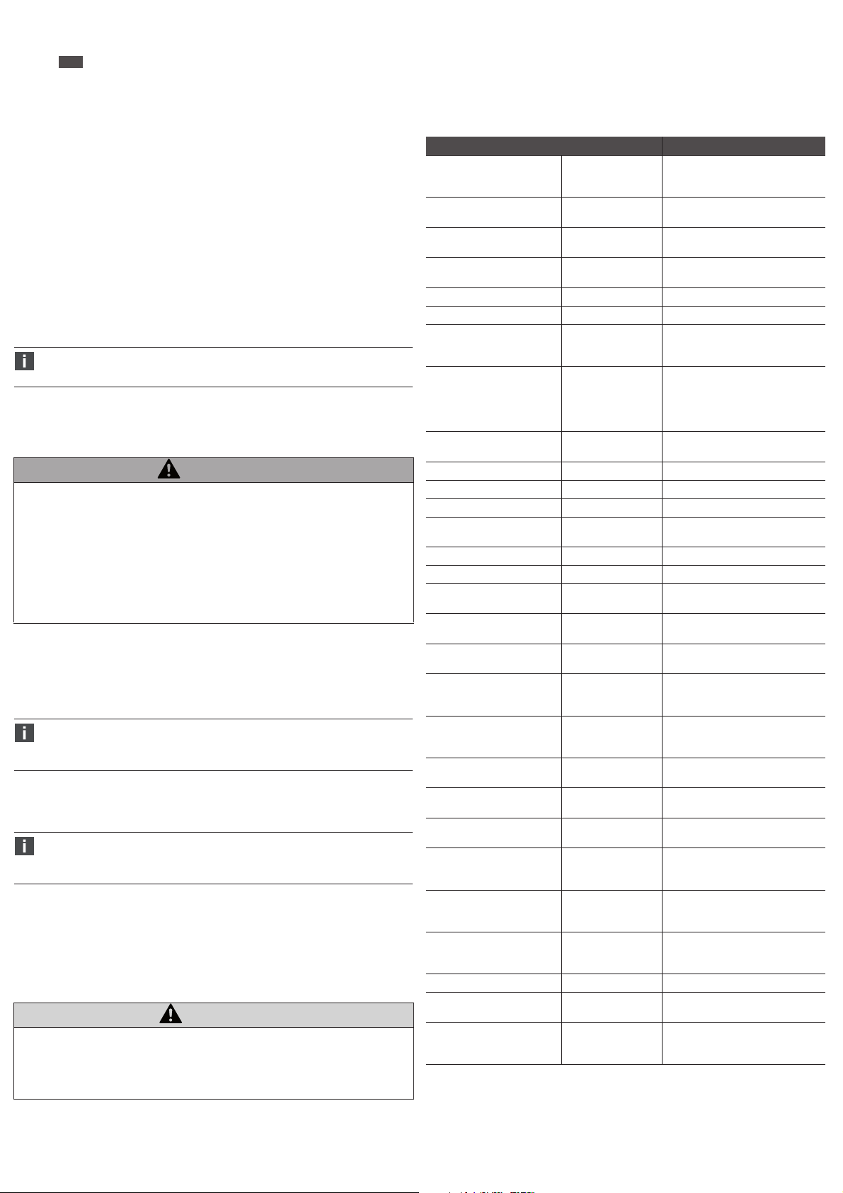
AVENTICS | AF2 | R412026496–BAL–001–AA | Italiano 47
8/2
Qa Menu
Questo menu contiene le impostazioni dell’uscita analogica.
Assegnazione dei parametri di misura all’uscita corrente
O Assegnare nel sottomenu Mode i parametri di misura come portata, temperatura o
pressione all’uscita corrente.
Assegnazione del valore finale del campo di misurazione
O Impostare nel sottomenu High il valore finale del campo di misurazione a 20 mA.
Assegnazione dell’inizio del campo di misurazione
O Impostare nel sottomenu Low l’inizio del campo di misurazione a 4 mA.
Impostazione dell’inversione dell’uscita corrente
O Impostare nel sottomenu Polarity l’inversione o meno dell’uscita corrente.
Impostazione del comportamento dell’uscita corrente i caso di errore nell’apparecchio
O Impostare nel sottomenu Fail il tipo di comportamento dell’uscita corrente in caso di errore.
Impostazione di un valore di corrente predefinito
O Impostare nel sottomenu Simulate un valore di corrente predefinito.
8 Messa in funzione e uso
Se entro 2 minuti non viene eseguita alcuna immissione, il display ritorna al
funzionamento normale. Le impostazioni non ancora confermate non vengono
applicate.
Prima di mettere in funzione il sistema, intraprendere e portare a termine i seguenti lavori:
W Montare e collegare completamente l’Durchflusssensor tenendo conto delle condizioni di
installazione (ved. anche “5 Montaggio”).
W Eseguire le preimpostazioni e la configurazione.
AVVERTENZA
Condizioni di funzionamento dell’impianto pericolose in caso di impostazioni errate del
flussometro o di superamento/mancato raggiungimento della tensione di esercizio del
flussometro
Pericolo di ferimento e di danneggiamento dell’impianto dovuto a condizioni di funzionamento
incontrollate.
O Durante il funzionamento non eseguire alcuna impostazione non idonea sul
Durchflusssensor. Si tenga presente che confermando le impostazioni inserite in
precedenza queste diventano subito effettive!
O Sostituire immediatamente i flussometri guasti!
O Non staccare il Durchflusssensor dal suo alimentatore durante il funzionamento!
Per mettere in funzione il flussometro procedere nel modo seguente:
1. Applicare la tensione di esercizio.
2. Alimentare la parte dell’impianto alla quale è collegato il Durchflusssensor.
3. Il sensore esegue un autotest in seguito al quale è pronto per il funzionamento. Viene
visualizzato il menu del valore di misura.
In c aso di probl emi du rante la mes sa in f unzio ne ved . “11 Messa ggi di errore e avvertim enti” .
L’Durchflusssensor non è dotato di interruttore principale. Dopo aver collegato
l’apparecchio all’alimentatore e l’alimentatore alla tensione di rete, l’Durchflusssensor
è acceso e pronto per l’uso. Per spegnere l’apparecchio basta staccare l’alimentatore
dall’alimentazione di corrente.
Messa in funzione breve (con impostazione di fabbrica)
La messa in funzione breve viene utilizzata per le applicazioni in condizioni di riferimento, ved.
“Condizioni di montaggio”.
Per la versione IO-Link tenere presente quanto segue:
In caso di impiego simultaneo delle uscite digitali Q1 e Q2 come IO-Link, o come uscita
di frequenza o d'impulso, insieme alle uscite analogiche Qa e Q2, potrebbero verificarsi
limitazioni della precisione delle uscite analogiche.
9 Manutenzione e riparazione
Il flussometro è esente da manutenzione.
Per la pulizia usare esclusivamente acqua ed eventualmente un detergente delicato.
Per informazioni sulla manutenzione dei filtri consultare le istruzioni dei filtri R412013436
(filtri AS1/AS2/AS3/AS5).
10 Smontaggio
ATTENZIONE
L’impianto è sottoposto ad alta pressione
Pericolo di ferimento e di danneggiamento dell’impianto dovuto a condizioni di funzionamento
incontrollate.
O Prima di procedere con lo smontaggio, togliere sempre l’alimentazione elettrica e
pneumatica della parte dell’impianto in cui è montato il Durchflusssensor.
1. Togliere l’alimentazione elettrica e pneumatica dell’impianto.
2. Svitare e rimuovere tutti i raccordi.
3. Svitare il flussometro dall’attacco di mandata (attacco filettato) con l’ausilio di una chiave
fissa o estrarre l’
Durchflusssensor
linearmente dal raccordo ad innesto.
11 Messaggi di errore e avvertimenti
Sul display del flussometro possono essere visualizzati i seguenti messaggi di errore e di
avvertimento se lo stato di errore interessato viene richiamato da una determinata condizione.
Esistono tre classificazioni: informazione, avviso ed errore.
Nella tabella seguente sono elencati tutti i messaggi di errore con riferimento al livello di errore
rilevante.
Messaggio Classificazione Descrizione
Memory Invalid Errore La memoria del sensore è
No MQTT Connection Avviso Impossibile stabilire un
Simulation active Info Simulazione attiva (segnale in uscita
Q1/2 Overtemp Avviso Driver per uscita di commutazione
Q1 Shortcut Avviso Cortocircuito in Q1
Q2 Shortcut Avviso Cortocircuito in Q2
Q2/a Overload Avviso Q2/a: la corrente non passa.
Q2/a OverTemp Avviso Q2/a: sovratemperatura del driver di
Q2 PulseConfig Avviso Configurazione non plausibile
Qa Overload Avviso Vedere Q2/a Overload
Qa OverTemp Avviso Vedere Q2/a OverTemp
Flow low Info Info Info: MBE -5%
Flow high info/avviso Info/avviso Info: MBE standard +5 %
Pressure low Avviso Aumentare la pressione
Pressure high Avviso Ridurre la pressione
Temperature low Avviso Aumentare la temperatura al valore
Temperature high Info/avviso Ridurre la temperatura al valore
Pressure low/high Error Errore Pressione di processo al di fuori del
Temperature low/high Error Errore Temperatura del fluido di processo
Energy Counter off - Air only Info Medium = Air => formula per il
Voltage low for Q1/2 Info Portare la tensione alla grandezza
Voltage low for Q2/a, Qa Info Portare la tensione alla grandezza
Voltage low for IO-Link Info Portare la tensione alla grandezza
Q1 Config out of Range Info Punti di commutazione
Q2 Config out of Range Info Punti di commutazione
Qa Config out of Range Info Punti di commutazione
Invalid Medium + RefCond Avviso RefCond valido solo per aria (Air)
Supply Voltage too low/high! Avviso Portare la tensione alla grandezza
Internal Temperature too low/
high!
danneggiata. Il flussometro deve
essere sostituito.
collegamento con MQTT Broker.
o grandezza di processo)
Q1/Q2 sovraccarico.
-Cavo non collegato?
-Impedenza eccessiva del carico?
uscita
-Ideale: carico di 500 ohm
-Temperatura ambiente troppo
elevata?
dell’uscita a impulso Q2
Avviso: MBE ampliato +5 %
specificato (ved. “13 Dati tecnici”).
specificato (ved. “13 Dati tecnici”).
campo di pressione consentito
al di fuori del campo temperatura
consentito
contatore di energia memorizzata
solo per l'aria, perciò non funzionale
specificata (ved. “13 Dati tecnici”).
specificata (ved. “13 Dati tecnici”).
specificata (ved. “13 Dati tecnici”).
parametrizzati al di fuori del campo
di misurazione
parametrizzati al di fuori del campo
di misurazione
parametrizzati al di fuori del campo
di misurazione
specificata (ved. “13 Dati tecnici”).
Portare la temperatura alla
grandezza specificata (ved. “13 Dati
tecnici”).
12 Smaltimento
Smaltire l’imballaggio e le parti usate nel rispetto delle norme vigenti nel paese di utilizzo.
Page 52

AVENTICS | AF2 | R412026496–BAL–001–AA | Italiano 48
13 Dati tecnici
Dati tecnici
Principio di misurazione Calorimetrico (portata)
Fluido Pressione (qualità dell’aria ISO 8573-1:2010 [3:4:4])
Campo di misurazione standard AS2: 5 ... 1060 l/min
Campo di misurazione ampliato AS2: 1060 ... 1590 l/min
Campo di visualizzazione AS2: 0 ... 3180 l/min
4 mA corrispondono a AS2: 0 l/min
20 mA corrispondono a AS2: 3200 l/min
Temperatura di processo -20 … +60 °C
Pressione di processo 0 … 16 bar
Interfaccia di comunicazione IO-Link 1.1 Com3 (solo versione IO-Link)
Display Display OLED da 128 x 128 pixel orientabile
Precisione del sensore
1)
Riproducibilità ±1,5 % del valore di misura
Tempo di reazione (T90) < 0,3 s
Precisione di misurazione
temperatura
Riproducibilità temperatura ±0,5 °C
Misurazione della pressione:
Precisione di misurazione ≤ ±1,5 % del campo di misurazione
Non-linearità ≤ ±0,5 % del campo di misurazione
Riproducibilità ≤ ±0,2 % del campo di misurazione
Tensione di alimentazione U
Potenza assorbita < 12 W (@ 24 VDC senza carico di uscita)
Tempo di inizializzazione ≤ 10 s
Classe di protezione III
Tipo di raccordo Connettore circolare M12x1, a 5 poli codifica A
4)
Segnale in uscita
Carico di uscita
1 uscita analogica 4 ... 20 mA, oppure 1 uscita di
4)
Livello inferiore del segnale
Livello superiore del segnale
Uscita digitale
Tensione di segnale HIGH
Tensione di segnale LOW
Carico induttivo
Carico capacitivo
4)
4)
4)
4)
4)
MTTF > 50 anni
Pt1200 (temperatura)
Piezoresistivo (pressione)
Elio, argon, azoto, biossido di carbonio
AS3: 8 ... 1630 l/min
AS5: 22 ... 4326 l/min
AS3: 1630 ... 2445 l/min
AS5: 4326 ... 6490 l/min
AS3: 0 ... 4890 l/min
AS5: 0 ... 12980 l/min
AS3: 0 l/min
AS5: 0 l/min
AS3: 5000 l/min
AS5: 13000 l/min
Ethernet (solo versione Ethernet) - OPC
UA, MQTT e Webserver
elettronicamente
(Rotazioni a 90°) e 4 tasti
±3 % del campo di misurazione +0,3 % del valore finale
del campo di misurazione standard
±8 % del campo di misurazione +1 % del valore finale del
campo di misurazione ampliato
±2 °C
(nel campo 10 … 30 °C)
2)
17 … 30 VDC
V
(versione IO-Link);
connettore circolare M12x1, a 8 poli codifica X
(versione Ethernet)
commutazione digitale / uscita a impulsi, di frequenza
configurabile, 1 uscita analogica 4 … 20 mA o 1 uscita
digitale (configurabile)
3)
4 .. 20 mA, 500 ohm, se Uv > 15 V
4)
3,5 ... 3,8 mA
4)
20,5 ... 21,5 mA
≤ 100 mA per ciascuna uscita
> Uv - 2 V
≤ 2 V
1H
100 nF (2,5 nF con IO-Link)
Raccordo di processo G3/8", G1/2", G1" (secondo la norma ISO 228-1)
Parti che vengono a contatto con il
Acciaio inox 1.4305, PA6, Viton®, alluminio
mezzo
Materiale corpo PC+ABS, PA66+PA6I GF50, PC, TPE, acciaio inox 1.4301
Tipo di protezione IP65 e IP67 (IP67 secondo la norma EN 60529)
Peso G3/8" 1300 g (850 g*)
G1/2" 2050 g (1250 g*)
G1" 2970 g (2300 g*)
*Senza fissaggio
Temperatura ambiente in
-20 ... +60 °C
funzionamento
Temperatura ambiente di
-40 ... +85 °C
magazzinaggio
Umidità relativa massima
≤ 90% RF, senza condensa
consentita
1) Condizioni di riferimento secondo la norma DIN 1343: pressione atmosferica 1,01325 bar temperatura ass.
aria compressa 0 °C
2) Tutti gli attacchi sono protetti dall’inversione di polarità e sono a prova di sovracorrenti. Q1, Q2 e Qa sono a
prova di cort o circuito.
3) Configurazione dell’uscita digitale: PNP/NPN/Push-pull.
4) Solo versione IO-Link
Per ulteriori dati tecnici consultare il catalogo online all’indirizzo
www.aventics.com/pneumatics-catalog
Page 53

Figure: l’immagine varia in base alla serie.
D1
AS2-AF2-G038
AS3-AF2-G012
AS5-AF2-G100
15,0
18,6
30,3
163,5
189,5
250,0
34,0
42,5
58,0
31,5
38,5
52,0
65
80
109
62
75
102
104
126
170
G3/8
G1/2
G1
45,5
B1
M12x1
IO-Link
M12
AB A
**)
*)
B
A
A
Ethernet
B
B
B2
35,5
73
D2
H3
H2
H1
D1
14,5
H4
51
18
110
D2 H1 H2 H3 H4 B1 B2
1
4
5
6
3
2
1
2
1
Ethernet
Info
Warn/Err
Eth
Web
MQTT
OPC
Industrial
Info
Warn/Err
Q1
IOLink
Q2/a
Qa
Info active
Warning/Error active
Ethernet
Web server
MQTT
OPC UA
Info active
Warning/Error active
Switch output
IO-Link active
Multi output
Analog output
2
3
3
6
1.
2.
3.
b
4.
a
AS2 19 x 1,8
AS2 : 0,5 Nm
M3 x 53
AS3 : 2,5 Nm
M5 x 68
AS5 : 3,0 Nm
M6 x 90
AS3 23 x 2
AS5
=
=
= 37 x 2,3
4 W03
1. 2.
3.
b
4.
AS2: 0,5 Nm
M3 x 53
AS3: 2,5 Nm
M5 x 68
AS5: 3,0 Nm
M6 x 90
AS2 19 x 1,8
AS3 23 x 2
AS5
=
=
= 37 x 2,3
a
5/1 W04
4.
3.
2.
1.
AS2 19 x 1,8
AS2: 0,5 Nm
M3 x 53
AS3: 2,5 Nm
M5 x 68
AS5: 3,0 Nm
M6 x 90
AS3 23 x 2
AS5
=
=
= 37 x 2,3
5/2 W05
5
6
4
3
7
2
8
1
RJ45M12
11
22
33
46
75
84
57
68
87654321
7
Montaggio con staffa di fissaggio
Dimensioni combinazione sensore/filtri
*) Filettatura interna
**) Direzione di flusso
Display
1 Riga di stato
2 Contenuto
3 Posizione orizzontale
$WWDFFR0[SROLFRGLILFD$,2/LQN
Panoramica sul prodotto
1 Connettore dell’apparecchio
(M12 8 poli codifica X
(versione Ethernet))
oppure
(M12 5 poli codifica A
(versione IO-Link))
2 OLED a colori 128x128 pixel
3 Tasti/tasti di comando
4 Targhetta di identificazione
5 Cella di misura calorimetrica
6 Cella di misura della pressione
(0 ... 16 bar)
1
52
3
4
Montaggio con set per il montaggio in batteria
Montaggio con set per il montaggio in batteria
$WWDFFR0[SROLFRGLILFD;(WKHUQHW
Page 54

8/1
AVENTICS | AF2 | R412026496–BAL–001–AA | Italiano 49
14 Panoramica dei menu
Link IO
Screen 1.1
(Kg/h) Display 1 Top
(m/s) Display 1 Btm (m/s)
Screen 1.2
(m³) Display 2 Top
(m³/h) Display 2 Btm
Screen 1.3
(kg) Display 3 Top
(kWh) Display 3 Btm
Hold for menu
Q1 Menu
Screen 2.1
60 min
Screen 2.2
24h
Screen 2.3
7days
Mode
SetPoint 1
SetPoint 2
Polarity
Simulate
DriverType
FunctionQ2 Menu Switch
Mode
SetPoint 1
SetPoint 2
Polarity
Simulate
DriverType
## # (unit)
abort
## # (unit)
abort
NormallyOpen
NormallyClosed
abort
Normal
Active
Inactive
abort
DRV
PNP
NPN
abort
Frequency
Pulse
Analog
abort
## # (unit)
abort
## # (unit)
abort
NormallyOpen
NormallyClosed
abort
Normal
Active
Inactive
abort
DRV
PNP
NPN
abort
Events
store
store
store
store
store
store
store
store
store
store
store
Status Signal
Info
Signal Quality
Info
Serial No.
Firmware
Switch Hyst Volumetric Flowrate
Switch Hyst Temperature
Switch Hyst Pressure
Switch Window Temperature
Switch Window Pressure
Switch Window Volumetric Flowrate
abort
Switch Hyst Volumetric Flowrate
Switch Hyst Temperature
Switch Hyst Pressure
Switch Window Temperature
Switch Window Pressure
Switch Window Volumetric Flowrate
abort
store
store
Page 55

8/2
AVENTICS | AF2 | R412026496–BAL–001–AA | Italiano 50
ModeQa Menu
High
Low
Polarity
Fail
Simulate
## # (unit)
abort
## # (unit)
abort
Normal
Inverted
abort
3.5 mA
21.5 mA
abort
SimO
3.5 mA
3.8 mA
4.0 mA
10.0 mA
12.0 mA
18.0 mA
20.0 mA
20.5 mA
21.5 mA
abort
store
store
store
store
store
UnitsDisplay MassFlowRat kg / h
FlowVelocity
Volume m
VolFlowRate
4 ... 20 mA Volumetric Flow Range
4 ... 20 mA Temperature
4 ... 20 mA Pressure
kg / min
g / s
m / s
fps
ft³
L
m
3
ft
3
ft
L / min
L / s
m
Mass kg
Energy kWh
Temperature
Pressure
Pages
°C
°F
bar
psi
Disp1 Top
Disp1 Btm
Disp2 Top
abort
abort
abort
3
abort
3
/ h
/ min
/ s
3
/ min
abort
abort
abort
abort
abort
store
store
store
store
store
store
store
store
store
MassFlowRate
Pressure
Temperature
Energy
Mass
VolumetricFlowRate
Volume
FlowVelocity
Disp2 Btm
Disp3 Top
Disp3 Btm
Disp History
abort
store
Page 56

8/3
AVENTICS | AF2 | R412026496–BAL–001–AA | Italiano 51
Simulate
Measure
Rotation 0°
ScreenSaver O
AutoOO O
Brightness 40 %
DisplayPin #_#_#_#
Flow
Temperature
Pressure
90°
180°
270°
abort
1 min
2 min
5 min
10 min
30 min
60 min
abort
1 min
2 min
5 min
10 min
30 min
60 min
abort
60 %
80 %
100 %
abort
abort
SimO
0 % ... 100 %
abort
SimO
0 % ... 100 %
abort
SimO
0 % ... 100 %
abort
Temperature
Pressure
SigQuality
store
store
store
store
store
store
store
store
Filter
Oset
Filter
SigQua2 ### %
SigQua3 ### %
SigQua4
OFF
100 ms
200 ms
500 ms
1 s
2 s
5 s
10 s
abort
##.#°[P]
abort
OFF
100 ms
200 ms
500 ms
1 s
2 s
5 s
10 s
abort
### % SigQua1
(read only)
abort
(read only)
abort
(read only)
abort
### %
(read only)
abort
store
store
store
store
store
store
store
MediumFlow
RefPress ## # bar
0-FlowO
0-FlowCut
Filter
Mode Standard
Air
Argon
Helium
CO2
Nitrogen
abort
abort
## #
abort
## ##
abort
OFF
100 ms
200 ms
500 ms
1 s
2 s
5 s
10 s
abort
(read only)
abort
store
store
store
store
store
store
8778OSIRefCond
User Defined
ISO2533
ISO1217
DIN1945-1
DIN1343
ISO6358
abort
store
Page 57

History
60 min Dynamic charts:
MassFlowRate
Pressure
Temperature
Energy
Mass
VolumetricFlowRate
Volume
FlowVelocity
abort
store
24 hours
7 days
Statistics
View max, mean, min values:
MassFlowRate
Pressure
Temperature
VolumetricFlowRate
FlowVelocity
abort
store
LastReset
(read only)
Reset (action required)
abort
store
Counter
Energy (read only)
LastReset
(read only)
Reset
(action required)
abort
store
Volume (read only)
Mass (read only)
System
Service #_#_#_#
abort
store
FactRes et (action required)
abort
store
SerialNumber
(read only)
DevTag ###
abort
store
AppTag
###
abort
store
FWVersion
(read only)
BLVersion
(read only)
HWVersion
(read only)
8/4
AVENTICS | AF2 | R412026496–BAL–001–AA | Italiano 52
Page 58

9/1
AVENTICS | AF2 | R412026496–BAL–001–AA | Italiano 53
Panoramica dei menu
Ethernet
Screen 1.1
(Kg/h) Display 1 Top
(m/s) Display 1 Btm (m/s)
Screen 1.2
(m³) Display 2 Top
(m³/h) Display 2 Btm
Screen 1.3
(kg) Display 3 Top
(kWh) Display 3 Btm
Hold for menu
Screen 2.1
60 min
Screen 2.2
24h
Screen 2.3
7days
DHCP ModeEthernet
IP Address
SubNetMask
Gateway
Name ### ### ### ###
StateWebserver
Port
ResetPW
StateOPC UA
Port #####
User # ... #
Password # ... #
StateMQTT Active
Broker
Port
Topic
User
Password
Events
Static IP
DHPC Client
abort
store
### ### ### ###
abort
### ### ### ###
abort
### ### ### ###
abort
abort
Active
Inactive
abort
store
#####
abort
store
(action required)
abort
store
Active
Inactive
abort
store
abort
store
abort
store
abort
store
Inactive
abort
store
### ### ### ###
abort
#####
abort
store
######/#/####
abort
######
abort
store
######
abort
store
store
store
store
store
store
store
Status Signal
Info
Signal Quality
Info
Serial No.
Firmware
Page 59

9/2
AVENTICS | AF2 | R412026496–BAL–001–AA | Italiano 54
Update ##### ms
abort
store
QoS QoS0
QoS1
QoS2
abort
UnitSend
store
Active
Inactive
abort
MassFlowRate
Active
Inactive
abort
FlowVelocity
Active
Inactive
abort
VolFlowRate
Active
Inactive
abort
Volume
Active
Inactive
abort
Mass
Active
Inactive
abort
Energy
Active
Inactive
abort
Temperature
Active
Inactive
abort
Pressure
Active
Inactive
abort
AdditInfos
Active
Inactive
abort
AdditInfos
Active
Inactive
abort
UnitsDisplay MassFlowRate kg / h
kg / min
g / s
abort
FlowVelocity
m / s
fps
abort
Volume m
3
ft³
L
abort
3
/ h
VolFlowRate
m
3
ft
/ min
3
/ s
ft
L / min
L / s
3
m
/ min
abort
Mass
kg
abort
Energy
kWh
abort
Temperature
°C
°F
abort
store
store
store
store
store
store
store
store
store
store
store
store
store
store
store
store
store
store
Page 60

9/3
AVENTICS | AF2 | R412026496–BAL–001–AA | Italiano 55
Simulate
Pressure
Rotation 0°
ScreenSaver O
AutoO O
Brightness
DisplayPin
Flow
Temperature
Pressure
90°
180°
270°
abort
10 s
30 s
60 s
abort
10 s
30 s
60 s
abort
40 %
60 %
80 %
100 %
abort
#_#_#_#
abort
SimO
0 % ... 100 %
abort
SimO
0 % ... 100 %
abort
SimO
0 % ... 100 %
abort
bar
psi
abort
store
MassFlowRateDisp Top1Pages
Pressure
Temperature
Disp1 Btm
Disp2 Top
Disp2 Btm
Disp3 Top
Disp3 Btm
Disp History
store
1 s
2 s
5 s
store
1 s
2 s
5 s
store
store
store
store
store
store
Energy
Mass
VolumetricFlowRate
Volum e
FlowVelocity
abort
store
Page 61

Measure MediumFlow
Air
Argon
Helium
CO2
Nitrogen
abort
store
8778OSIdnoCfeR
User Defined
ISO2533
ISO1217
DIN1945-1
DIN1343
ISO6358
abort
store
0-FlowO
abort
store
0-FlowCut
## #
## ##
abort
store
Filter
OFF
100 ms
200 ms
500 ms
1 s
2 s
5 s
10 s
abort
store
Mode Standard
(read only)
abort
store
Temperature
OFF
100 ms
200 ms
500 ms
1 s
2 s
5 s
10 s
abort
store
Pressure
Filter
Oset
Filter OFF
100 ms
200 ms
500 ms
1 s
2 s
5 s
10 s
abort
store
##.#°[P]
abort
store
SigQuality SigQua1 ### %
(read only)
abort
store
SigQua2
(read only)
abort
store
SigQua3
### %
### %
(read only)
abort
store
SigQua4 ### %
(read only)
abort
store
History 60 min Dynamic charts:
MassFlowRate
Pressure
Temperature
Energy
Mass
VolumetricFlowRate
Volume
FlowVelocity
abort
store
24 hours
7 days
Statistics View max, mean, min values:
MassFlowRate
Pressure
Temperature
VolumetricFlowRate
FlowVelocity
abort
store
LastReset
(read only)
Reset (action required)
abort
store
Counter
Energy (read only)
LastReset
(read only)
Reset (action required)
(action required)
abort
store
Volume (read only)
Mass (read only)
RefPress ## # bar
abort
store
System Service
abort
store
FactReset
abort
store
SerialNumber
(read only)
DevTag
#_#_#_#
###
abort
store
AppTag
###
abort
store
FWVersion
(read only)
BLVersion
(read only)
HWVersion
(read only)
9/4
AVENTICS | AF2 | R412026496–BAL–001–AA | Italiano 56
Page 62

AVENTICS | AF2 | R412026496–BAL–001–AA | Español 57
2
1/1
1/2
Español
1 Acerca de esta documentación
Estas instrucciones contienen información importante para montar, utilizar, mantener y eliminar
averías sencillas del Durchflusssensor de un modo seguro y apropiado.
O Lea estas instrucciones por completo, especialmente el capítulo 2 “Indicaciones de
seguridad”, antes de trabajar con el Durchflusssensor.
Normas aplicadas
Este producto cumple con las exigencias de las siguientes normas o ensayos normativos:
W Conforme con la Directiva sobre compatibilidad electromagnética 2014/30/UE
W Emisión perturbadora y resistencia contra interferencias EN 61326-2-3
Documentación necesaria y complementaria
O Datos técnicos y dimensiones según el catálogo online
O Tenga en cuenta también las instrucciones de otros componentes de instalación (p. ej.,
unidades de mantenimiento de la serie AS).
O Observe la documentación del fabricante de la instalación.
O Asimismo, tenga en cuenta las normativas y reglamentos aplicables de las legislaciones
europea y nacional, así como las disposiciones vigentes en su país relativas a prevención de
accidentes laborales y protección del medio ambiente.
Presentación de la información
Indicaciones de advertencia
En estas instrucciones, las indicaciones de advertencia se hallan antes de las indicaciones de
manejo que presentan peligro de daños personales o materiales. Se deben respetar las medidas
descritas de protección ante peligros.
Estructura de las indicaciones de advertencia
PALABRA DE ADVERTENCIA
Tipo y fuente de peligro
Consecuencias si se ignora la advertencia de peligro
O Medidas para evitar situaciones de peligro
Significado de las palabras de aviso
ADVERTENCIA
Identifica una situación de peligro con riesgo de lesiones graves, incluso mortales, en caso de
que no se evite.
ATENCIÓN
Identifica una situación de peligro en la que puede existir riesgo de lesiones de carácter leve o
leve-medio en caso de que no se evite.
Símbolos
Si no se tiene en cuenta esta información, puede empeorarse el desarrollo del servicio.
2 Indicaciones de seguridad
El Durchflusssensor ha sido fabricado de acuerdo al estado actual de la técnica y las normas de
seguridad técnica reconocidas. A pesar de ello, existe riesgo de daños personales y materiales
si no se tienen en cuenta las siguientes instrucciones de seguridad ni los avisos de advertencia
ante indicaciones de manejo incluidas en esta documentación.
O Lea estas instrucciones con detenimiento y por completo antes de trabajar con el
Durchflusssensor.
O Guarde estas instrucciones en un lugar al que siempre puedan acceder fácilmente todos los
usuarios.
O Entregue siempre el Durchflusssensor a terceros junto con las instrucciones de servicio.
Utilización conforme a las especificaciones
O Utilice el Durchflusssensor únicamente para medir el caudal de aire comprimido (Air), argón,
helio, dióxido de carbono (CO2) y nitrógeno gaseoso (Nitrogen) conforme a las
especificaciones técnicas aplicables en el ámbito industrial.
O Respete los límites de potencia mencionados en los datos técnicos.
O El aparato está diseñado solo para ser montado en unidades de mantenimiento de la serie
AS o para montaje individual usando escuadras de fijación.
La utilización conforme a las especificaciones también incluye que se hayan leído y entendido
estas instrucciones y, en especial, el capítulo “Indicaciones de seguridad”.
Utilización no conforme a las especificaciones
Se considera una utilización no conforme a las especificaciones aquellos casos en que el
Durchflusssensor:
W se emplea en sistemas hidráulicos o se aplica con líquidos o gases agresivos, explosivos,
inflamables o tóxicos,
W se utiliza con modificaciones en el aparato,
W se emplea para fines de cálculo en tráfico comercial, p. ej., cómputo de aire consumido en
instalaciones de suministro.
Cualificación del personal
Es necesario tener conocimientos básicos de electrónica y neumática, así como de la
terminología especializada pertinente, para realizar el montaje, desmontaje, puesta en servicio
y manejo del Durchflusssensor. Por lo tanto, solamente personal cualificado en electrónica o
neumática o bien otra persona vigilada y controlada por una persona cualificada podrá realizar
el montaje, el desmontaje, la puesta en servicio y su manejo.
Por personal cualificado se entiende una persona que, en virtud de su formación especializada,
sus conocimientos y experiencia, así como su conocimiento acerca de las normas vigentes,
puede evaluar los trabajos que se le han encomendado, detectar potenciales peligros y adoptar
medidas de seguridad adecuadas. El personal cualificado debe respetar las normas en vigor
específicas del sector.
Indicaciones de seguridad generales
W Observe la normativa en materia de seguridad, prevención de accidentes y protección
medioambiental vigente en el país de aplicación y en el puesto de trabajo.
W Como norma general, no está permitido modificar ni transformar el sensor de caudal. En
caso de no tener en cuenta las indicaciones recogidas en estas instrucciones o de realizar
intervenciones en el aparato, desaparece cualquier tipo de responsabilidad y prescribe la
garantía de los aparatos y accesorios.
W Todos los ajustes en el sensor de caudal, todos los trabajos de montaje y desmontaje, así
como la puesta en servicio deben ser efectuados únicamente por personal cualificado.
W No suelte ningún cable de conexión ni mangueras en sistemas que se encuentren bajo
tensión eléctrica o bajo presión.
W No someta el sensor de caudal a cargas derivadas de flexión, torsión o choque.
W Asegúrese de que se respeta la clase de calidad de aire para el medio de caudal. Cualquier
suciedad en el aire comprimido puede dañar el aparato y provocar fallos de medición y de
funcionamiento. Como consecuencia, se pueden transmitir señales no intencionadas a las
salidas que provoquen daños personales y materiales.
W La medición de caudal en el Durchflusssensor solo funciona correctamente si se utilizan
cables de unión AVENTICS de la serie CON-RD - M12x1 (véase el catálogo online).
O Realice los cortes transversales de los conectores de los cables de suministro aferentes del
usuario según las normas vigentes. En Alemania, tenga en cuenta las siguientes normas:
DIN VDE 0100 (parte 430) y DIN VDE 0298 (parte 4) o DIN VDE 0891 (parte 1).
O Ejecute los circuitos eléctricos conectados en el aparato como circuitos eléctricos SELV y
PELV (SELV = Safety Extra Low Voltage = baja tensión de seguridad; PELV = baja tensión
especial protegida).
Durante el montaje y la puesta en servicio
W Desconecte siempre la presión y la conexión con la red eléctrica de la pieza de la instalación
que corresponda antes de montar o desmontar el sensor de caudal.
W Asegúrese de que los conductos de aire comprimido conectados estén libres de partículas
de impurezas y de que no penetre en el aparato ningún líquido a lo largo de los conductos
conectados.
W No monte ningún aparato que presente signos claros de daño y sustituya inmediatamente
los aparatos defectuosos.
W Verifique que el rango de medición del aparato (véase “13 Datos técnicos”) corresponda al
caudal máximo en el lugar de montaje previsto.
Durante el funcionamiento y el manejo
W Si se produce una avería, sustituya el Durchflusssensor de inmediato.
W Asegúrese de que no se sobrepasan los valores admisibles de temperatura y presión.
W La combinación de filtros/sensores no puede modificarse, ya que de lo contrario la
calibración estaría obsoleta.
3 Volumen de suministro
W 1 Combinación de filtros de sensor
W 1 manual de instrucciones de servicio
4 Sobre este producto
El sensor de caudal está disponible en dos versiones:
W Versión IO-Link
W Versión Ethernet
Principio de funcionamiento
El sensor de caudal utiliza el principio de medición calorimétrica. El sensor mide el efecto de
refrigeración del medio que fluye a través de la sonda calentada. Cuanto mayor es la velocidad
de flujo del medio, mayor es el efecto de refrigeración de la sonda calentada.
El sensor tiene dos salidas de conmutación configurables Q1 y Q2 (únicamente en la versión
IO-Link) para el caudal, la presión o la temperatura.
Además, en la salida de conmutación (Q1) hay una interfaz IO-Link disponible
Ámbitos de uso
El sensor de caudal sobre todo es adecuado para:
W La medición de aire comprimido y de gases no corrosivos y no inflamables en máquinas
W Control del consumo energético del aire comprimido en máquinas y en la distribución de
presión
W Control de fugas en los conductos de aire comprimido de máquinas
W Medición de gases inertes en el envasado de alimentos
Encontrará las dimensiones del sensor de caudal en las figuras y .
Page 63

AVENTICS | AF2 | R412026496–BAL–001–AA | Español 58
4
5/1
5/2
5/1
5/2
1/1
1/267
6
7
6
7
1
5Montaje
ATENCIÓN
Peligro de lesiones por un funcionamiento descontrolado
Si durante el montaje del Durchflusssensor la instalación se encuentra bajo tensión eléctrica
y/o presión, esto puede provocar reacciones descontroladas y en consecuencia lesiones o
daños en la instalación.
O Desconecte siempre la tensión y la presión de la parte correspondiente de la instalación
antes de realizar las conexiones eléctricas y neumáticas del Durchflusssensor.
Condiciones de montaje
W Mantenga siempre el lugar de montaje fácilmente accesible y libre de vibraciones.
W Respete un espacio libre mínimo de 150 mm para la unidad del transmisor del sensor de
caudal.
W Tenga en cuenta la temperatura ambiente (véase “13 Datos técnicos”) y también la
irradiación de calor del medio de medición.
W El medio de medición debe corresponder al menos a la clase de pureza 3:4:4 o mejor, según
ISO 8573-1:2010.
W El medio de medición y el aire ambiente no se pueden condensar.
W Monte el sensor de caudal después del secador de aire en las redes de aire comprimido.
W Si no hay secadora, instale el sensor de caudal después del separador de condensado y de
filtros adecuados.
No instale el Durchflusssensor directamente detrás de un regulador/filtro regulador. Se
debe usar exclusivamente la combinación de filtros/sensores descrita.
Opciones de montaje
W Montaje con estribo de fijación (W05)
W Montaje con juego de unión (W03)
Encontrará los accesorios necesarios en el catálogo online en
https://www.aventics.com/pneumatics-shop
Conexión del aire comprimido
O Respete los valores límite de presión y temperatura (véase “13 Datos técnicos”).
O Al realizar la conexión tenga en cuenta la dirección del caudal (entrada izquierda; salida
derecha)
1. Alinee el Durchflusssensor teniendo en cuenta la dirección del caudal y conecte el
Durchflusssensor a la unidad de mantenimiento o al juego de unión adecuado para el
conducto (véase
2. Monte la combinación de aparatos o el Durchflusssensor con el juego de unión o una
escuadra de fijación. Al realizar el montaje asegúrese de que la unión atornillada quede
perfectamente estanca.
3. A continuación, aplique presión a la sección de conducto y verifique que toda la instalación
es estanca y funciona correctamente.
y ).
Instalación eléctrica
Daños en el aparato o funcionamiento imprevisto por trabajos bajo tensión
Un funcionamiento imprevisto durante los trabajos bajo tensión puede provocar lesiones y
daños en el aparato.
O Desconecte la presión y la tensión del sistema antes de ejecutar los siguientes trabajos:
– Trabajos de cableado
– Unión y separación de conexiones eléctricas
O ¡Durante los trabajos en la instalación eléctrica, tenga en cuenta las normativas de
seguridad aplicables!
O Encienda la tensión de alimentación del aparato solamente tras concluir los trabajos de
conexión y comprobar detenidamente los trabajos de cableado.
Daños en el aparato por tensión de alimentación incorrecta
Una tensión de alimentación incorrecta puede provocar daños en el aparato.
O El aparato solo debe funcionar con una baja tensión protegida y un aislamiento eléctrico
seguro de la clase de protección III.
Nota acerca del tendido de cables de datos
O Use cables de datos blindados con conductores trenzados por pares (twisted pair).
O Desarrolle un concepto de apantallado óptimo y completo.
O Tienda y conecte los cables siempre de conformidad con la compatibilidad
electromagnética para evitar perturbaciones, por ejemplo de convertidores CC-CC,
motores, reguladores sincronizados y contactores.
O No tienda los cables en paralelo con cables del motor o de la alimentación de
corriente en canales de cables durante tramos largos.
o (W04)
ADVERTENCIA
ATENCIÓN
Solo se consigue la clase de protección IP67 y/o IP69 para el aparato bajo las
siguientes condiciones:
W El cable enchufado en la conexión M12 está atornillado.
W La cubierta está atornillada (sin hueco entre la cubierta superior y la carcasa superior).
W En caso de incumplimiento, el aparato corresponde a un tipo de protección IP no
especificado.
Conexión eléctrica del sensor de caudal
El Durchflusssensor dispone en la parte superior de una conexión M12x1 de 5 polos u 8 polos
(véase , , y ) para la alimentación de tensión y las salidas.
O Solo está permitido utilizar el Durchflusssensor mediante un suministro de
corriente con un seccionamiento seguro de la red (PELV según
, IEC 60364-4-41, HD 60364.4.41,
410
estar sin potencial (no conectado a tierra).
O Para la conexión del Durchflusssensor, utilice cables de unión AVENTICS de la
serie CON-RD - M12x1.
O Monte el conector por enchufe redondo CON-RD - M12x1 con cuidado para garantizar que se
mantiene el tipo de protección IP 67.
En caso de que no se utilice la conexión, esta se debe cubrir con una tapa adecuada para
conservar el tipo de protección IP 65 de la carcasa.
O Tenga en cuenta la ocupación de pines (véase la Tab. 1 y , Tab. 2 y )
O El sensor de caudal (IO-Link) posee dos salidas de conmutación o una comunicación IO-Link
o dos salidas analógicas. Las salidas de conmutación de los contactos 5 y 4 se pueden utilizar
como tipo NO, NC y cablear según corresponda en cada caso, véase “13 Datos técnicos”.
O Utilice cables blindados si el Durchflusssensor está expuesto a fuertes campos
electromagnéticos.
O En el caso de los alargadores con extremos abiertos, asegúrese de que los extremos de los
conductores desnudos no se tocan (¡peligro de cortocircuito en caso de tensión de
alimentación encendida!).
O Aísle los conductores entre sí de forma correspondiente.
O Asegure el aparato con un fusible separado al inicio del circuito eléctrico aferente.
Tab. 1 asignación de pines, conector por enchufe M12, 5 polos (solo versión IO-Link, véase )
Contacto
(M12)
1L
2 QA blanco Salida de corriente analógica 4 ... 20 mA
3 M azul Masa, masa de referencia para salida de
4C/Q
5Q
Tab. 2 asignación de pines, conector por enchufe M12, 8 polos (solo versión Ethernet, véase )
Contacto
(M12)
11blanco/
2 2 naranja TX (-) + POE TxData -
3 3 blanco/verde RX (+) - POE RxData+
4 6 Verde RX (-) - POE RxData-
75blanco/azulPOE+
84azulPOE+
57blanco/
68marrónPOE-
Así se conecta el Durchflusssensor eléctricamente:
O Enrosque el conector M12x1 del cable de unión CON-RD en la conexión del sensor de caudal
().
Después de conectar la tensión de alimentación y una vez transcurrido el tiempo de espera en
el arranque (aprox. 1 s), el aparato se encuentra en modo de ejecución o modo Run (modo
operativo normal).
Conecte el cable según su función. Tras establecer la tensión de alimentación, la pantalla
muestra el valor de medición actual.
Identificación Color del hilo Descripción
+
1
/QB Amarillo Salida digital 2 (salida de conmutación) o
2
RJ45 Color del hilo Identificación 10/100 Mbit
EN 60079-14
marrón Tensión de alimentación
negro Salida digital 1 (salida de conmutación) o
naranja
marrón
). El circuito eléctrico debe
(escalable)
corriente
comunicación IO-Link
salida de pulso/frecuencia/analógica
4...20mA (escalable)
TX (+) + POE TxData+
POE-
DIN VDE 0100-
Page 64

AVENTICS | AF2 | R412026496–BAL–001–AA | Español 59
3
8/1
9/4
8/1
9/4
8/2
8/3
9/2
9/3
8/3
9/3
8/3
9/4
8/4
9/4
8/4
9/4
6 Elementos de mando e indicación
pantalla
En modo normal, la pantalla muestra los valores y símbolos siguientes:
1. Línea de estado
2. Valores de medición (caudal, presión ...)
3. Posición del menú
Fundamentos de manejo
Debajo de la pantalla, el Durchflusssensor cuenta con cuatro teclas que permiten manejar los
menús de configuración, seleccionar funciones y valores, y cambiar la indicación.
Si está seleccionada la configuración básica, siempre se enciende la iluminación de fondo la
primera vez que se pulsa una tecla.
El idioma de la pantalla es inglés y no se puede modificar.
Menú de configuración
Una vez conectada la alimentación de tensión de las salidas, puede configurar el
Durchflusssensor para el funcionamiento. En este proceso se especifican, entre otros, datos
sobre las unidades de medida, sobre la indicación y sobre las salidas. A continuación, puede
proteger el acceso introduciendo un código de seguridad (véase “Adjudicación de un PIN de 4
dígitos para proteger contra el manejo o la manipulación”).
Estructura de menús
En las figuras hasta se muestra una vista general de los principales menús.
Si durante 2 minutos no se pulsa ninguna tecla, la pantalla cambia automáticamente a
la indicación estándar con el valor de medición actual.
7 Introducción de parámetros
Véanse también las figuras hasta .
Manejo de la versión de Ethernet y IO-Link
O Pulse una tecla de flecha cualquiera durante al menos 2 segundos para acceder al menú
respectivo y realizar ajustes.
Pantalla , , ,
Ajuste de las unidades
O En el 1º submenú, seleccione Units y en el 2º submenú MassFlowRate, FlowVelocity,
Volume, VolFlowRate, Mass, Energy, Temperature o Pressure.
Ajuste de la indicación de Screen 1.1
O En el submenú Pages, seleccione la opción Disp1Top.
Ajuste de la indicación de Screen 1.1
O En el submenú Pages, seleccione la opción Disp1Btm.
Ajuste de la indicación de Screen 1.2
O En el submenú Pages, seleccione la opción Disp2Top.
Ajuste de la indicación de Screen 1.2
O En el submenú Pages, seleccione la opción Disp2Btm.
Ajuste de la indicación de Screen 1.3
O En el submenú Pages, seleccione la opción Disp3Top.
Ajuste de la indicación de Screen 1.3
O En el submenú Pages, seleccione la opción Disp3Btm.
Indicación Screen 2.1, 2.2. y 2.3
O En el submenú DispHistory, ajuste los parámetros de indicación.
Optimización de la legibilidad
O En el submenú Rotation, ajuste la indicación 0°, 90°, 180° o 270° para garantizar una
legibilidad óptima.
Tiempo para la activación del protector de pantalla
O En el submenú ScreenSaver, ajuste el tiempo tras el cual se activa el protector de pantalla.
Tiempo para la desconexión de la pantalla
O En el submenú AutoOff, ajuste el tiempo para la desconexión de la pantalla.
Luminosidad en %
O En el submenú Brightness, ajuste el porcentaje de luminosidad.
Adjudicación de un PIN de 4 dígitos para proteger contra el manejo o la manipulación
En el submenú Display Pin
O
, adjudique un pin de 4 dígitos.
Simulate ,
Simulación de caudal
O Simule el caudal en el submenú Flow.
Simulación de temperatura
O En el submenú Temperature, simule la temperatura.
Simulación de presión
O En el submenú Pressure, simule la presión.
Measure ,
Ajuste del medio de medición
O En el submenú Flow, seleccione la opción Medium y ajuste el medio de medición:
–Air
–Argon
–Helium
–CO2
–Nitrogen
Ajuste de la norma/estándar de referencia
O En el submenú Flow, seleccione la opción RefCond y ajuste la norma de referencia/el
estándar de referencia:
– ISO2533
– ISO1217
– DIN1945-1
– DIN1343
– ISO6358
– ISO8778
– UserDefined (específico del usuario)
Ajuste de la presión de referencia en caso de ajuste específico del usuario (UserDefined)
O En el submenú Flow, seleccione la opción RefCond y seleccione UserDefined (presión de
referencia específica de la aplicación).
Ajuste del desplazamiento del punto cero
O En el submenú Flow, seleccione la opción 0-FlowOff y ajuste el desplazamiento del punto
cero.
Ajuste de la supresión de valores ínfimos
O En el submenú Flow, seleccione la opción 0-FlowCut y ajuste la supresión de valores
ínfimos.
Ajuste el filtro del valor medio para filtrar los valores de medición en la indicación y en la
salida (alisar)
O En el submenú Flow/Pressure/Temperature, seleccione la opción Filter para filtrar los
valores de medición en la indicación y en la salida.
Ajuste del offset/desplazamiento del punto cero
O En el submenú Pressure, seleccione la opción Offset para ajustar el offset/desplazamiento
del punto cero.
Selección de la calidad de la señal
O En el submenú SigQuality, seleccione entre SigQua1, SigQua2, SigQua3 y SigQua4. Todos
están al 100 %. La calidad de señal 1 es una medida de la robustez.
History ,
Selección de la indicación/el gráfico de los valores de medición de los últimos 60 minutos
O En el submenú 60 min, seleccione la indicación/el gráfico de los valores de medición de los
últimos 60 minutos.
Selección de la indicación/el gráfico de los valores de medición de las últimas 24 horas
O En el submenú 24 hour, seleccione la indicación/el gráfico de los valores de medición de las
últimas 24 horas.
Selección de la indicación/el gráfico de los valores de medición de los últimos 7 días
O En el submenú 7days, seleccione la indicación/el gráfico de los valores de medición de los
últimos 7 días.
Statistics ,
Valores mín./medios/máx. de los parámetros individuales tras el último reseteo
O En el submenú View se muestran max, mean, min values para los parámetros individuales
después del último reseteo.
Visualización del momento del último reseteo (read only)
O En el submenú LastReset se muestra el momento del último reseteo.
Restablecimiento de los valores estadísticos a 0
O En el submenú Reset, restablezca los valores estadísticos a “0”.
Page 65

AVENTICS | AF2 | R412026496–BAL–001–AA | Español 60
8/4
9/4
8/4
9/4
9/1
9/1
9/4
9/1
9/1
9/1
9/2
8/1
8/2
8/1
8/1
8/2
Counter ,
Visualización de los contadores
O Seleccione entre los submenús Mass, Volume, Energy, lastReset para visualizar los
contadores.
Restablecimiento de los contadores
O Seleccione el submenú Reset para restablecer los contadores.
System ,
Inicio de sesión del servicio
O En el submenú Service, efectúe un inicio de sesión del servicio para usuarios autorizados.
Restablecimiento al ajuste de fábrica
O En el submenú FactReset, restablezca el sistema al ajuste de fábrica.
Serial Number (read only)
O En el submenú SerialNumber, visualice el número de serie.
Ajuste de Device-Tag
O En el submenú DevTag, configure un Device-Tag.
Ajuste de Application-Tag
O En el submenú AppTag, configure un Application-Tag.
FWVersion (read only)
O En el submenú FWVersion, visualice la versión de firmware.
Calibration (read only)
O En el submenú Calibration, visualice los ajustes por defecto del firmware.
BLVersion (read only)
O En el submenú BLVersion, visualice la versión de Bootload.
HWVersion (read only)
O En el submenú HWVersion, visualice la versión de hardware.
Manejo de la versión de Ethernet
Ethernet
Se aplica para todos los sensores de caudal con la clave de tipo sensor de caudal ASx-AF2-ETH.
A continuación se especifican los ajustes recomendados en los respectivos submenús de arriba
a abajo, véanse también las Figuras hasta .
O Asigne una dirección dinámica o estática.
O En el submenú DHCP Mode, asigne la dirección.
Configuración de la dirección IP
O En el submenú IP Address, asigne la dirección IP.
SubNetMask
O En el submenú SubNetMask, asigne la máscara de subred.
Gateway
O En el submenú Gateway, ajuste la dirección de puerta de enlace.
Webserver
Conexión y desconexión de la interfaz web
O En el submenú State, seleccione entre Active e Inactive.
Configuración del puerto
O Seleccione el submenú Port para configurar el puerto.
Restablecimiento de la contraseña por parte del usuario
O En el submenú ResetPW, restablezca la contraseña de usuario de Webserver.
OPC UA
Conexión y desconexión de la interfaz web
O En el submenú State, seleccione entre Active e Inactive.
Configuración del puerto
O Seleccione el submenú Port y configure el puerto.
Ajuste del nombre de usuario
O Seleccione el submenú User y configure el nombre de usuario.
Adjudicación de la contraseña
O Seleccione el submenú Password y ajuste la contraseña.
MQTT ,
Conexión y desconexión de la interfaz web
O Seleccione el submenú State y configure Active o Inactive.
Broker
O Seleccione el submenú Broker para configurar el broker.
Configuración del puerto
O Seleccione el submenú Port para configurar el puerto.
Top ic
O Seleccione el submenú Topic y muestre los temas.
Usuario
O Seleccione el submenú User e introduzca el nombre de usuario para el broker.
Creación de la contraseña de broker
O Seleccione el submenú Password e introduzca la contraseña de broker.
Envío del intervalo de corte al broker
O Seleccione el submenú Update y establezca el intervalo de forma correspondiente.
QoS
O Seleccione el submenú QoS e introduzca QoS-0, QoS-1 o QoS-2.
Definición del mensaje MQTT al broker
O Seleccione el submenú Send, después seleccione una opción de menú del segundo submenú
(Unit hasta AppStatistic) y configure Active o Inactive.
Manejo de la versión IO-Link
Se aplica para todos los sensores de caudal con la clave de tipo sensor de caudal ASx-AF2-FLX.
La pantalla muestra el menú del valor de medición con el ajuste por defecto (kg/h, m/s).
O Pulse una tecla de flecha cualquiera de forma prolongada (mín. 2 segundos) y después
seleccione el menú Q1 Menu, Q2 Menu o Qa Menu.
A continuación se especifican los ajustes recomendados en los respectivos submenús de arriba
a abajo, véanse también las Figuras hasta .
W En Q1 Menu y Q2 Menu se puede ajustar la salida de conmutación.
W En Qa Menu se puede ajustar la salida analógica.
Q1 Menu
Este menú contiene los ajustes de la salida de conmutación 1.
Ajuste de la histéresis o función de ventana
O En el menú Mode, efectúe el ajuste del modo para la histéresis o la función de ventana con
los parámetros de medición correspondientes.
Ajuste del punto de conmutación
O En el submenú SetPoint1, ajuste el punto de conmutación.
Ajuste del punto de retroceso/histéresis o del límite de ventana inferior
O En el submenú SetPoint2, ajuste el punto de retroceso/la histéresis o el límite de ventana
inferior.
Ajuste del comportamiento de conmutación del contacto de reposo
O Seleccione el submenú Polarity y después elija entre NormallyClosed y NormallyOpen.
Simulación de una salida de conmutación
O Seleccione el submenú Simulate y después Active, Inactive o Normal (modo de medición).
Ajuste de PNP/NPN o Push/Pull (DRV)
O Seleccione el submenú DriverType y ajuste PNP, NPN o Push/Pull (DRV).
Q2 Menu ,
Este menú contiene los ajustes de la salida de conmutación 2.
Ajuste de la salida de conmutación como frecuencia, pulso, analógica o salida de
conmutación
O Seleccione el submenú Function y efectúe el ajuste correspondiente.
Ajuste del modo para histéresis o función de ventana
O Seleccione el submenú Mode y efectúe el ajuste correspondiente.
Ajuste del punto de conmutación
O En el submenú SetPoint1, ajuste el punto de conmutación.
Ajuste del punto de retroceso/histéresis o del límite de ventana inferior
O En el submenú SetPoint2, ajuste el punto de retroceso/la histéresis o el límite de ventana
inferior.
Ajuste del comportamiento de conmutación del contacto de reposo
O Seleccione el submenú Polarity y después elija entre NormallyClosed y NormallyOpen.
Simulación de una salida de conmutación
O Seleccione el submenú Simulate y después elija entre Active, Inactive y Normal (modo de
medición).
Ajuste de PNP/NPN o Push/Pull
O Seleccione el submenú DriverType y ajuste PNP, NPN o Push/Pull (DRV).
Page 66

AVENTICS | AF2 | R412026496–BAL–001–AA | Español 61
8/2
Qa Menu
Este menú contiene los ajustes de la salida analógica.
Asignación de la salida de corriente a los parámetros de medición
O En el submenú Mode, asigne los parámetros de medición, como caudal, temperatura o
presión a la salida de corriente.
Asignación del valor final del rango de medición
O En el submenú High, establezca el valor final del rango de medición en 20 mA.
Asignación del inicio del rango de medición
O En el submenú Low, establezca el inicio del rango de medición en 4 mA.
Ajuste de la inversión de la salida de corriente
O En el submenú Polarity, ajuste si se debe invertir la salida de corriente.
Ajuste del comportamiento de la salida de corriente en caso de un error en el aparato
O En el submenú Fail, ajuste cómo se debe comportar la salida de corriente en caso de un
error.
Ajuste del valor de corriente predefinido
O En el submenú Simulate, ajuste un valor de corriente predefinido.
8 Puesta en servicio y funcionamiento
Si no se introduce nada durante más de 2 minutos, el indicador vuelve al modo de
indicación. Los ajustes aún no confirmados no se aceptarán.
Antes de poner en servicio el sistema, se deben haber realizado y finalizado los siguientes
trabajos:
W Ha montado y conectado completamente el Durchflusssensor teniendo en cuenta las
condiciones de montaje (véase también “5 Montaje”).
W Ha efectuado los ajustes previos necesarios y la configuración.
ADVERTENCIA
Estados de funcionamiento peligrosos de la instalación por ajustes incorrectos en el sensor
de caudal o por sobrepasar o no alcanzar la tensión de servicio del sensor de caudal
Peligro de lesiones y de dañar la instalación a causa de estados de funcionamiento
descontrolados de la instalación.
O No efectúe ajustes indebidos en el Durchflusssensor durante el funcionamiento. Tenga en
cuenta que al confirmar los ajustes efectuados previamente, estos pasarán a tener efecto
de inmediato.
O Sustituya inmediatamente los sensores de caudal averiados.
O No desconecte el Durchflusssensor de su fuente de tensión durante el funcionamiento.
Así se pone en servicio el sensor de caudal:
1. Aplique la tensión de servicio.
2. Presurice la pieza de la instalación en la que está conectado el Durchflusssensor.
3. El sensor realiza una autocomprobación y después está listo para el funcionamiento. Se
muestra el menú del valor de medición.
En caso de problemas durante la puesta en servicio, véase “11 Mensajes de error y de
advertencia”.
El Durchflusssensor no dispone de interruptor principal. Después de haber conectado el
aparato al bloque de alimentación y este a la tensión nominal, el Durchflusssensor está
encendido y operativo. Para apagarlo simplemente se debe desenchufar el bloque de
alimentación de la alimentación de corriente.
Puesta en servicio rápida (con ajustes de fábrica)
La puesta en servicio rápida se usa en aplicaciones bajo condiciones de referencia, véase
“Condiciones de montaje”.
En la versión IO-Link hay que tener en cuenta lo siguiente:
Si se usan simultáneamente salidas digitales Q1 y Q2 como IO-Link, salida de frecuencia
o salida de pulso, con las salidas analógicas Qa y Q2, se pueden dar limitaciones de la
precisión de las salidas analógicas.
9 Mantenimiento y reparación
El sensor de caudal está exento de mantenimiento.
Para la limpieza, utilice exclusivamente agua o, en caso necesario, un detergente suave.
Encontrará información acerca del mantenimiento de los filtros en el manual de los mismos
R412013436 (filtros AS1/AS2/AS3/AS5).
10 Desmontaje
ATENCIÓN
La instalación se encuentra bajo alta presión
Peligro de lesiones y de dañar la instalación a causa de estados de funcionamiento
descontrolados de la instalación.
O Antes de empezar con el desmontaje, desconecte siempre la tensión y la presión de la
parte de la instalación en la que está montado el Durchflusssensor.
1. Desconecte la tensión y la presión de la instalación.
2. Afloje y retire todas las conexiones.
3. Afloje el sensor de caudal de la conexión de presión (orificio roscado) con ayuda de una llave
de boca o retire el
Durchflusssensor
del racor instantáneo en línea recta.
11 Mensajes de error y de advertencia
Se muestran los siguientes errores y mensajes de advertencia en la pantalla del sensor de
caudal cuando el estado de error relevante ha sido causado por una condición determinada.
Hay tres clasificaciones: información, advertencia y error.
En la siguiente tabla se enumeran todos los mensajes de error con referencia al nivel de error
relevante.
Mensaje Clasificación Descripción
Memory Invalid Error El acumulador del sensor está
No MQTT Connection Advertencia No es posible realizar una conexión
Simulation active Información Simulación activa (señal de salida o
Q1/2 Overtemp Advertencia Controlador para la salida de
Q1 Shortcut Advertencia Cortocircuito en Q1
Q2 Shortcut Advertencia Cortocircuito en Q2
Q2/a Overload Advertencia Q2/a: la corriente no fluye.
Q2/a OverTemp Advertencia Q2/a: exceso de temperatura del
Q2 PulseConfig Advertencia Configuración no plausible de la
Qa Overload Advertencia Véase Q2/a Overload
Qa OverTemp Advertencia Véase Q2/a OverTemp
Flow low Info Información Info: MBE -5 %
Flow high Info/Warning Información/
Advertencia
Pressure low Advertencia Aumentar presión
Pressure high Advertencia Disminuir presión
Temperature low Advertencia Aumente la temperatura al valor
Temperature high Información/
Advertencia
Pressure low/high Error Error Presión del proceso fuera del
Temperature low/high Error Error Temperatura del medio del proceso
Energy Counter off - Air only Información Medium = Air => Fórmula para el
Voltage low for Q1/2 Información Aplique la tensión con la magnitud
Voltage low for Q2/a, Qa Información Aplique la tensión con la magnitud
Voltage low for IO-Link Información Aplique la tensión con la magnitud
Q1 Config out of Range Información Puntos de conmutación
Q2 Config out of Range Información Puntos de conmutación
Qa Config out of Range Información Puntos de conmutación
Invalid Medium + RefCond Advertencia RefCond solo válido para aire (Air)
Supply Voltage too low/high! Advertencia Aplique la tensión con la magnitud
Internal Temperature too low/
high!
dañado. Se debe sustituir el sensor
de caudal.
al MQTT Broker.
tamaño del proceso)
conmutación Q1/Q2 sobrecargado.
-¿Cable no conectado?
-¿Carga de ohmiaje demasiado alto?
controlador de salida
-Ideal: Carga de 500 Ohmios
-¿Temperatura ambiente demasiado
alta?
salida de pulso Q2
Información: Estándar -MBE +5 %
Advertencia: -MBE ampliado +5 %
especificado (véase “13 Datos
técnicos”).
Disminuya la temperatura al valor
especificado (véase “13 Datos
técnicos”).
margen de presión admisible
fuera del rango de temperatura
admisible
contador de energía solo registrada
para aire, por tanto sin función
especificada (véase “13 Datos
técnicos”).
especificada (véase “13 Datos
técnicos”).
especificada (véase “13 Datos
técnicos”).
parametrizados fuera del margen de
medición
parametrizados fuera del margen de
medición
parametrizados fuera del margen de
medición
especificada (véase “13 Datos
técnicos”).
Lleve la temperatura a la magnitud
especificada (véase “13 Datos
técnicos”).
Page 67

AVENTICS | AF2 | R412026496–BAL–001–AA | Español 62
12 Eliminación de residuos
Elimine el embalaje y las piezas gastadas de acuerdo con las especificaciones del país en el que
se vaya a utilizar el sistema.
13 Datos técnicos
Datos técnicos
Principio de medición Calorimétrico (caudal)
Fluido Presión (calidad de aire ISO°8573-1:2010 [3:4:4])
Rango de medición estándar AS2: 5 ... 1060 l/min
Rango de medición ampliado AS2: 1060 ... 1590 l/min
Rango de indicación AS2: 0 ... 3180 l/min
Corresponde a 4 mA AS2: 0 l/min
Corresponde a 20 mA AS2: 3200 l/min
Temperatura del proceso -20 … +60 °C
Presión del proceso 0 … 16 bar
Interfaz de comunicación IO-Link 1.1 Com3 (exclusivamente versión IO-Link)
pantalla Pantalla OLED giratoria electrónica de 128 x 128 píxeles
Precisión del elemento sensor
Reproducibilidad ±1,5 % del valor de medición
Tiempo de reacción (T90) < 0,3 s
Precisión de medición de la
temperatura
Reproducibilidad de la
temperatura
Medición de presión:
Precisión de medición ≤ ±1,5 % del rango de medición (en el rango 10 … 30 °C)
Sin linealidad ≤ ±0,5 % del rango de medición
Reproducibilidad ≤ ±0,2 % del rango de medición
Tensión de alimentación U
Consumo de potencia < 12 W (@ 24 VDC sin carga de salida)
Tiempo de inicialización ≤ 10 s
Clase de protección III
Tipo de conexión Conector redondo M12x1, 5 polos codificación A (versión
4)
Señal de salida
Carga de salida
Nivel de señal inferior
Nivel de señal superior
Salida digital
Tensión de señal HIGH
Tensión de señal LOW
Carga inductiva
Carga capacitiva
1 x salida analógica 4 ... 20 mA, o 1 x salida de
4)
4)
4)
4)
4)
4)
4)
4)
MTTF > 50 años
Pt1200 (temperatura)
piezorresistivo (presión)
Helio, argón, nitrógeno, dióxido de carbono
AS3: 8 ... 1630 l/min
AS5: 22 ... 4326 l/min
AS3: 1630 ... 2445 l/min
AS5: 4326 ... 6490 l/min
AS3: 0 ... 4890 l/min
AS5: 0 ... 12980 l/min
AS3: 0 l/min
AS5: 0 l/min
AS3: 5000 l/min
AS5: 13000 l/min
Ethernet (exclusivamente versión Ethernet) - OPC
UA, MQTT y Webserver
(giros de 90°) y 4 teclas
1)
±3 % del valor de medición +0,3 % del valor del rango de
medición estándar
±8 % del valor de medición +1 % del valor del rango de
medición ampliado
±2 °C
±0,5 °C
2)
17 … 30 VDC
V
IO-Link);
conector redondo M12x1, 8 polos codificación X (versión
Ethernet)
conmutación digital / salida de pulso, salida de
frecuencia, configurable, 1 x salida analógica 4 … 20 mA
o 1 x salida de conmutación digital (configurable)
4 .. 20 mA, 500 ohmios, si Uv > 15 V
3,5 ... 3,8 mA
20,5 ... 21,5 mA
≤ 100 mA por salida
> Uv - 2 V
≤ 2 V
1H
100 nF (2,5 nF en IO-Link)
3)
Conexión de proceso G3/8", G1/2", G1" (según DIN ISO 228-1)
Piezas en contacto con el medio Acero inoxidable 1.4305, PA6, Viton®, aluminio
Material de la carcasa PC+ABS, PA66+PA6I GF50, PC, TPE, acero inoxidable
1.4301
Tipo de protección IP65 e IP67 (IP67 según EN 60529)
Peso G3/8" 1300 g (850 g*)
G1/2" 2050 g (1250 g*)
G1" 2970 g (2300 g*)
*sin fijación
Temperatura ambiente de
-20 ... +60°C
funcionamiento
Temperatura ambiente de
-40 ... +85°C
almacenamiento
Máxima humedad relativa
≤ 90% HR, sin condensación
permitida
1) Condiciones de referencia según DIN 1343: presión atmosférica 1,01325 bar fuera de temperatura de aire
comprimido 0 °C
2) Todas las conexiones tienen protección contra las inversiones de polaridad y son resistentes a la
sobrecorriente. Q1, Q2 y Qa son resistentes a cortocircuitos.
3) Configuración de la salida digital: PNP/NPN/Push-Pull.
4) Únicamente versión IO-Link
Puede consultar más datos técnicos en el catálogo online en
www.aventics.com/pneumatics-catalog
Page 68

Figuras: la vista varía en función de la serie.
D1
AS2-AF2-G038
AS3-AF2-G012
AS5-AF2-G100
15,0
18,6
30,3
163,5
189,5
250,0
34,0
42,5
58,0
31,5
38,5
52,0
65
80
109
62
75
102
104
126
170
G3/8
G1/2
G1
45,5
B1
M12x1
IO-Link
M12
AB A
**)
*)
B
A
A
Ethernet
B
B
B2
35,5
73
D2
H3
H2
H1
D1
14,5
H4
51
18
110
D2 H1 H2 H3 H4 B1 B2
1
4
5
6
3
2
1
2
1
Ethernet
Info
Warn/Err
Eth
Web
MQTT
OPC
Industrial
Info
Warn/Err
Q1
IOLink
Q2/a
Qa
Info active
Warning/Error active
Ethernet
Web server
MQTT
OPC UA
Info active
Warning/Error active
Switch output
IO-Link active
Multi output
Analog output
2
3
3
6
1.
2.
3.
b
4.
a
AS2 19 x 1,8
AS2 : 0,5 Nm
M3 x 53
AS3 : 2,5 Nm
M5 x 68
AS5 : 3,0 Nm
M6 x 90
AS3 23 x 2
AS5
=
=
= 37 x 2,3
4 W03
1. 2.
3.
b
4.
AS2: 0,5 Nm
M3 x 53
AS3: 2,5 Nm
M5 x 68
AS5: 3,0 Nm
M6 x 90
AS2 19 x 1,8
AS3 23 x 2
AS5
=
=
= 37 x 2,3
a
5/1 W04
4.
3.
2.
1.
AS2 19 x 1,8
AS2: 0,5 Nm
M3 x 53
AS3: 2,5 Nm
M5 x 68
AS5: 3,0 Nm
M6 x 90
AS3 23 x 2
AS5
=
=
= 37 x 2,3
5/2 W05
5
6
4
3
7
2
8
1
RJ45M12
11
22
33
46
75
84
57
68
87654321
7
Montaje con estribo de fijación
Dimensiones de la combinación de filtros de sensor
*) Rosca interior
**) Dirección del caudal
Pantalla
1 Línea de estado
2 Contenido
3 Posición horizontal
&RQH[LyQ0[SRORVFRGLILFDFLyQ$,2/LQN
Vista general de productos
1 Conector del aparato
(M12 8 polos codificación X
(versión Ethernet))
o
(M12 5 polos, codificación A
(versión IO-Link))
2 OLED de colores 128x128 píxeles
3 Teclas/teclas de manejo
4 Placa de características
5 Célula de medición calorimétrica
6 Célula de medición de presión
(0...16 bar)
1
52
3
4
Montaje con juego de unión
Montaje con juego de unión
&RQH[LyQ0[SRORVFRGLILFDFLyQ;(WKHUQHW
Page 69

8/1
AVENTICS | AF2 | R412026496–BAL–001–AA | Español 63
14 Vista general del menú
IO-Link
Screen 1.1
(Kg/h) Display 1 Top
(m/s) Display 1 Btm (m/s)
Screen 1.2
(m³) Display 2 Top
(m³/h) Display 2 Btm
Screen 1.3
(kg) Display 3 Top
(kWh) Display 3 Btm
Hold for menu
Q1 Menu
Screen 2.1
60 min
Screen 2.2
24h
Screen 2.3
7days
Mode
SetPoint 1
SetPoint 2
Polarity
Simulate
DriverType
FunctionQ2 Menu Switch
Mode
SetPoint 1
SetPoint 2
Polarity
Simulate
DriverType
## # (unit)
abort
## # (unit)
abort
NormallyOpen
NormallyClosed
abort
Normal
Active
Inactive
abort
DRV
PNP
NPN
abort
Frequency
Pulse
Analog
abort
## # (unit)
abort
## # (unit)
abort
NormallyOpen
NormallyClosed
abort
Normal
Active
Inactive
abort
DRV
PNP
NPN
abort
Events
store
store
store
store
store
store
store
store
store
store
store
Status Signal
Info
Signal Quality
Info
Serial No.
Firmware
Switch Hyst Volumetric Flowrate
Switch Hyst Temperature
Switch Hyst Pressure
Switch Window Temperature
Switch Window Pressure
Switch Window Volumetric Flowrate
abort
Switch Hyst Volumetric Flowrate
Switch Hyst Temperature
Switch Hyst Pressure
Switch Window Temperature
Switch Window Pressure
Switch Window Volumetric Flowrate
abort
store
store
Page 70

8/2
AVENTICS | AF2 | R412026496–BAL–001–AA | Español 64
ModeQa Menu
High
Low
Polarity
Fail
Simulate
## # (unit)
abort
## # (unit)
abort
Normal
Inverted
abort
3.5 mA
21.5 mA
abort
SimO
3.5 mA
3.8 mA
4.0 mA
10.0 mA
12.0 mA
18.0 mA
20.0 mA
20.5 mA
21.5 mA
abort
store
store
store
store
store
UnitsDisplay MassFlowRat kg / h
FlowVelocity
Volume m
VolFlowRate
4 ... 20 mA Volumetric Flow Range
4 ... 20 mA Temperature
4 ... 20 mA Pressure
kg / min
g / s
m / s
fps
ft³
L
m
3
ft
3
ft
L / min
L / s
m
Mass kg
Energy kWh
Temperature
Pressure
Pages
°C
°F
bar
psi
Disp1 Top
Disp1 Btm
Disp2 Top
abort
abort
abort
3
abort
3
/ h
/ min
/ s
3
/ min
abort
abort
abort
abort
abort
store
store
store
store
store
store
store
store
store
MassFlowRate
Pressure
Temperature
Energy
Mass
VolumetricFlowRate
Volume
FlowVelocity
Disp2 Btm
Disp3 Top
Disp3 Btm
Disp History
abort
store
Page 71

8/3
AVENTICS | AF2 | R412026496–BAL–001–AA | Español 65
Simulate
Measure
Rotation 0°
ScreenSaver O
AutoOO O
Brightness 40 %
DisplayPin #_#_#_#
Flow
Temperature
Pressure
90°
180°
270°
abort
1 min
2 min
5 min
10 min
30 min
60 min
abort
1 min
2 min
5 min
10 min
30 min
60 min
abort
60 %
80 %
100 %
abort
abort
SimO
0 % ... 100 %
abort
SimO
0 % ... 100 %
abort
SimO
0 % ... 100 %
abort
Temperature
Pressure
SigQuality
store
store
store
store
store
store
store
store
Filter
Oset
Filter
SigQua2 ### %
SigQua3 ### %
SigQua4
OFF
100 ms
200 ms
500 ms
1 s
2 s
5 s
10 s
abort
##.#°[P]
abort
OFF
100 ms
200 ms
500 ms
1 s
2 s
5 s
10 s
abort
### % SigQua1
(read only)
abort
(read only)
abort
(read only)
abort
### %
(read only)
abort
store
store
store
store
store
store
store
MediumFlow
RefPress ## # bar
0-FlowO
0-FlowCut
Filter
Mode Standard
Air
Argon
Helium
CO2
Nitrogen
abort
abort
## #
abort
## ##
abort
OFF
100 ms
200 ms
500 ms
1 s
2 s
5 s
10 s
abort
(read only)
abort
store
store
store
store
store
store
8778OSIRefCond
User Defined
ISO2533
ISO1217
DIN1945-1
DIN1343
ISO6358
abort
store
Page 72

History
60 min Dynamic charts:
MassFlowRate
Pressure
Temperature
Energy
Mass
VolumetricFlowRate
Volume
FlowVelocity
abort
store
24 hours
7 days
Statistics
View max, mean, min values:
MassFlowRate
Pressure
Temperature
VolumetricFlowRate
FlowVelocity
abort
store
LastReset
(read only)
Reset (action required)
abort
store
Counter
Energy (read only)
LastReset
(read only)
Reset
(action required)
abort
store
Volume (read only)
Mass (read only)
System
Service #_#_#_#
abort
store
FactRes et (action required)
abort
store
SerialNumber
(read only)
DevTag ###
abort
store
AppTag
###
abort
store
FWVersion
(read only)
BLVersion
(read only)
HWVersion
(read only)
8/4
AVENTICS | AF2 | R412026496–BAL–001–AA | Español 66
Page 73

9/1
AVENTICS | AF2 | R412026496–BAL–001–AA | Español 67
Vista general del menú
Ethernet
Screen 1.1
(Kg/h) Display 1 Top
(m/s) Display 1 Btm (m/s)
Screen 1.2
(m³) Display 2 Top
(m³/h) Display 2 Btm
Screen 1.3
(kg) Display 3 Top
(kWh) Display 3 Btm
Hold for menu
Screen 2.1
60 min
Screen 2.2
24h
Screen 2.3
7days
DHCP ModeEthernet
IP Address
SubNetMask
Gateway
Name ### ### ### ###
StateWebserver
Port
ResetPW
StateOPC UA
Port #####
User # ... #
Password # ... #
StateMQTT Active
Broker
Port
Topic
User
Password
Events
Static IP
DHPC Client
abort
store
### ### ### ###
abort
### ### ### ###
abort
### ### ### ###
abort
abort
Active
Inactive
abort
store
#####
abort
store
(action required)
abort
store
Active
Inactive
abort
store
abort
store
abort
store
abort
store
Inactive
abort
store
### ### ### ###
abort
#####
abort
store
######/#/####
abort
######
abort
store
######
abort
store
store
store
store
store
store
store
Status Signal
Info
Signal Quality
Info
Serial No.
Firmware
Page 74

9/2
AVENTICS | AF2 | R412026496–BAL–001–AA | Español 68
Update ##### ms
abort
store
QoS QoS0
QoS1
QoS2
abort
UnitSend
store
Active
Inactive
abort
MassFlowRate
Active
Inactive
abort
FlowVelocity
Active
Inactive
abort
VolFlowRate
Active
Inactive
abort
Volume
Active
Inactive
abort
Mass
Active
Inactive
abort
Energy
Active
Inactive
abort
Temperature
Active
Inactive
abort
Pressure
Active
Inactive
abort
AdditInfos
Active
Inactive
abort
AdditInfos
Active
Inactive
abort
UnitsDisplay MassFlowRate kg / h
kg / min
g / s
abort
FlowVelocity
m / s
fps
abort
Volume m
3
ft³
L
abort
3
/ h
VolFlowRate
m
3
ft
/ min
3
/ s
ft
L / min
L / s
3
m
/ min
abort
Mass
kg
abort
Energy
kWh
abort
Temperature
°C
°F
abort
store
store
store
store
store
store
store
store
store
store
store
store
store
store
store
store
store
store
Page 75

9/3
AVENTICS | AF2 | R412026496–BAL–001–AA | Español 69
Simulate
Pressure
Rotation 0°
ScreenSaver O
AutoO O
Brightness
DisplayPin
Flow
Temperature
Pressure
90°
180°
270°
abort
10 s
30 s
60 s
abort
10 s
30 s
60 s
abort
40 %
60 %
80 %
100 %
abort
#_#_#_#
abort
SimO
0 % ... 100 %
abort
SimO
0 % ... 100 %
abort
SimO
0 % ... 100 %
abort
bar
psi
abort
store
MassFlowRateDisp Top1Pages
Pressure
Temperature
Disp1 Btm
Disp2 Top
Disp2 Btm
Disp3 Top
Disp3 Btm
Disp History
store
1 s
2 s
5 s
store
1 s
2 s
5 s
store
store
store
store
store
store
Energy
Mass
VolumetricFlowRate
Volum e
FlowVelocity
abort
store
Page 76

Measure MediumFlow
Air
Argon
Helium
CO2
Nitrogen
abort
store
8778OSIdnoCfeR
User Defined
ISO2533
ISO1217
DIN1945-1
DIN1343
ISO6358
abort
store
0-FlowO
abort
store
0-FlowCut
## #
## ##
abort
store
Filter
OFF
100 ms
200 ms
500 ms
1 s
2 s
5 s
10 s
abort
store
Mode Standard
(read only)
abort
store
Temperature
OFF
100 ms
200 ms
500 ms
1 s
2 s
5 s
10 s
abort
store
Pressure
Filter
Oset
Filter OFF
100 ms
200 ms
500 ms
1 s
2 s
5 s
10 s
abort
store
##.#°[P]
abort
store
SigQuality SigQua1 ### %
(read only)
abort
store
SigQua2
(read only)
abort
store
SigQua3
### %
### %
(read only)
abort
store
SigQua4 ### %
(read only)
abort
store
History 60 min Dynamic charts:
MassFlowRate
Pressure
Temperature
Energy
Mass
VolumetricFlowRate
Volume
FlowVelocity
abort
store
24 hours
7 days
Statistics View max, mean, min values:
MassFlowRate
Pressure
Temperature
VolumetricFlowRate
FlowVelocity
abort
store
LastReset
(read only)
Reset (action required)
abort
store
Counter
Energy (read only)
LastReset
(read only)
Reset (action required)
(action required)
abort
store
Volume (read only)
Mass (read only)
RefPress ## # bar
abort
store
System Service
abort
store
FactReset
abort
store
SerialNumber
(read only)
DevTag
#_#_#_#
###
abort
store
AppTag
###
abort
store
FWVersion
(read only)
BLVersion
(read only)
HWVersion
(read only)
9/4
AVENTICS | AF2 | R412026496–BAL–001–AA | Español 70
Page 77

AVENTICS | AF2 | R412026496–BAL–001–AA | Svenska 71
2
1/1
1/2
Svenska
1 Om denna dokumentation
Denna bruksanvisning innehåller viktig information för att montera och driftsätta
Durchflusssensor på ett säkert och fackmannamässigt sätt. Den innehåller även information om
skötsel och underhåll samt enkel felsökning.
O Du bör läsa igenom hela bruksanvisningen noga, särskilt kapitlet 2 ”Säkerhetsföreskrifter”
på sidan , innan du börjar arbeta med Durchflusssensorn.
Tillämpliga standarder
Vi försäkrar att denna produkt överensstämmer med följande standard eller standarddokument:
W Konformitet enligt EMV-riktlinje 2014/30/EU
W Störningssignal och styrka EN 61326-2-3
Nödvändig och kompletterande dokumentation
O Tekniska data och mått enligt online-katalog
O Följ även bruksanvisningarna för övriga systemkomponenter (t.ex. luftbehandlingsenheter
serie AS).
O Observera anläggningsdokumentation för anläggningstillverkaren.
O Följ dessutom allmänna, lagstadgade föreskrifter och övriga bindande föreskrifter i
europeisk resp. nationell lagstiftning samt de föreskrifter för att undvika olycka på
arbetsplatsen och för att skydda miljön som gäller i användarlandet.
Återgivning av information
Varningsinformation
I denna bruksanvisning anges varningar före en hanteringsanvisning om det finns risk för
person- eller materialskada. De åtgärder som beskrivs för att avvärja faror måste följas.
Varningsanvisningarnas uppbyggnad
SIGNALORD
Typ av fara eller riskkälla
Följder om faran inte beaktas
O Åtgärder för att förhindra faran
Signalordens betydelse
VARNING
Markerar en farlig situation som kan leda till svåra skador eller till och med dödsfall, om den
inte avvärjs.
SE UPP
Markerar en farlig situation som kan orsaka lätta till medelsvåra personskador om den inte
avvärjs.
Symboler
Om denna information inte iakttas, kan det leda till att driften försämras.
2 Säkerhetsföreskrifter
Durchflusssensor har tillverkats i överensstämmelse med dagens tekniska standard och
erkända säkerhetstekniska regler. Trots detta finns det risk för person- och materialskador om
man inte beaktar följande allmänna säkerhetsföreskrifter samt de specifika
varningsupplysningar som finns i denna bruksanvisning.
O Läs därför igenom hela bruksanvisningen noggrant innan du börjar arbeta med
Durchflusssensorn.
O Förvara denna anvisning så att den alltid är tillgänglig för alla användare.
O Bruksanvisningen ska alltid medfölja om Durchflusssensor överlämnas till tredje part.
Tillåten användning
O Använd Durchflusssensorn uteslutande för flödesmätning av tryckluft (Air), Argon, Helium,
Koldioxid (CO2) och kväve (nitrogen) i gasform inom industrin enligt den tekniska
specifikationen.
O Håll dig inom de effektgränser som anges i tekniska data.
O Enheten är avsedd för montering i luftbehandlingsenheter i serie AS eller för separat
montering med hjälp av fästvinklar.
Avsedd användni ng innebär också att du har läst och först ått denna bruksanvisning och speci ellt
kapitlet ”Säkerhetsföreskrifter”.
Ej avsedd användning
Ej avsedd användning innebär att Durchflusssensor används
W i hydrauliska system, eller att den utsätts för aggressiva eller brännbara gaser eller vätskor,
W efter att den modifierats,
W för avräkning i kommersiella syften, t.ex. för beräkning av luftförbrukning i
matningsanordningar.
Förkunskapskrav
Montering, demontering, driftstart och handhavande av Durchflusssensorn kräver
grundläggande kunskaper om elektronik och pneumatik liksom kunskap om de tillämpliga
facktermerna. Montering, demontering, driftstart och manövrering får därför endast utföras av
en fackman inom el och pneumatik eller av en instruerad person under ledning och uppsikt av
en fackman.
Med fackman avses en person som till följd av sin yrkesutbildning, sina kunskaper och
erfarenheter liksom sin kännedom om tillämpliga bestämmelser kan bedöma anförtrott arbete,
upptäcka möjliga faror och vidta nödvändiga säkerhetsåtgärder. Fackmannen måste iaktta
tillämpliga yrkesmässiga regler.
Allmänna säkerhetsanvisningar
W Beakta de föreskrifter som gäller i Sverige och på arbetsplatsen för att undvika olycka och
för att skydda miljön.
W Flödessensorn får aldrig byggas om eller förändras. Om anvisningarna i denna
bruksanvisning inte följs, eller om ingrepp görs i enheten, upphör vårt ansvar att gälla.
Garantin gäller inte för enheten eller tillbehörsdelar.
W Alla inställningar på Flödessensorn, alla monterings- och demonteringsarbeten och
driftstart får bara utföras av utbildad fackpersonal.
W Lossa inga kablar och slangar på system som står under elektrisk spänning eller tryck!
W Belasta inte Flödessensorn genom böjning, torsion eller slag.
W Kontrollera att den föreskrivna luftkvalitetsklassen för flödesmediet uppfylls. Föroreningar i
tryckluften kan skada enheten och leda till mätfel och funktionsstörningar. Det kan i sin tur
orsaka oavsiktliga signaler i utgångarna och därmed skador på personer och material.
W Tryckflödesmätningen i Durchflusssensor fungerar bara korrekt om AVENTICS
anslutningskablar i serie CON-RD - M12x1 används (se online-katalogen).
O Välj kabel med lämplig area i enlighet med giltiga standarder.
O Anslut enheten som SELV- och PELV-strömkrets från (SELV = Safety Extra Low Voltage =
säkerhetsspänning; PELV = skyddad speciell lågspänning).
Vid montering och driftstart
W Koppla alltid den aktuella anläggningsdelen spänningsfri och trycklös innan Flödessensorn
monteras eller demonteras.
W Kontrollera att anslutna tryckluftsledningar är fria från smutspartiklar och att inga vätskor
kan tränga in i enheten utmed de anslutna ledningarna.
W Montera inte in uppenbart skadade enheter och byt omedelbart ut dem om de är defekta.
W Kontrollera att enhetens mätområde motsvarar det maximala flödet på monteringsplatsen
(se ”13 Tekniska data”).
Vid drift och manövrering
W Byt omedelbart ut Durchflusssensorn om störningar uppstår.
W Kontrollera att de tillåtna värdena för temperatur och tryck inte överskrids.
W Sensor / filterkombinationen får inte ändras, annars kommer inte kalibreringen att stämma.
3 Leveransen innehåller
W 1 Sensorfilterkombination
W 1 Bruksanvisning
4 Om denna produkt
Flödessensorn finns i två versioner:
W IO-länk-Version
W Ethernet-version
Funktionsprincip
Flödessensorn använder den kalorimetriska mätprincipen. Sensorn mäter kylningseffekten av
mediet som strömmar genom den uppvärmda sonden. Ju högre flödeshastighet för mediet,
desto högre kylningseffekt av den uppvärmda sonden.
Sensorn har två konfigurerbara kopplingsutgångar Q1 och Q2 (endast IO-länk-version) för flöde,
tryck eller temperatur.
Dessutom finns ett IO-länk-gränssnitt tillgängligt vid kopplingsutgången (Q1),
Användningsområden
Flödessensorn är framför allt lämpad för:
W Mätning av tryckluft samt icke-frätande och icke-brandfarliga gaser i maskiner
W Kontroll av energiförbrukning av tryckluft på maskiner och i tryckfördelning
W Övervakning av läckor i tryckluftsledningar på maskiner
W Mätning av inerta gaser i livsmedelsförpackningar
Dimensionerna för Flödessensorn finns i illustrationerna och .
Page 78

AVENTICS | AF2 | R412026496–BAL–001–AA | Svenska 72
4
5/1
5/2
5/1
5/2
1/1
1/2
6
7
6
7
6
7
1
5Montering
SE UPP
Risk för personskador på grund av okontrollerad drift
Om anläggningen står under elektrisk spänning och/eller tryck när Durchflusssensorn
monteras, kan det leda till okontrollerade reaktioner som kan orsaka personskador eller
skador på anläggningen.
O Gör alltid den aktuella anläggningsdelen trycklös och spänningsfri innan
Durchflusssensorn ansluts pneumatiskt eller elektriskt.
Monteringsförutsättningar
W Håll monteringsplatsen lättillgänglig och fri från vibrationer.
W Håll ett minimumsavstånd på 150 mm för Flödessensorn sändarenhet.
W Observera omgivningstemperaturen (se ”13 Tekniska data”) och värmestrålningen i
mätmediet.
W Mätmediet måste minst hålla renhetsklass 3: 4: 4 eller bättre enligt ISO 8573-1:2010.
W Mätmediet och omgivningsluften får inte kondensera.
W I tryckluftsnät, installera Flödessensorn efter lufttorken.
W Om det inte finns en tork, installera Flödessensorn efter kondensavskiljaren och lämpliga
filter.
Montera inte Flödessensorn direkt bakom en regulator/filterregulator. Det är bara den
föreskrivna sensorn/filterkombinationen som ska användas.
Monteringsalternativ
W Montering med montagebygel (W05)
W Montering med blockmonteringssats (W03)
De nödvändiga tillbehören finns i onlinekatalogen på
https://www.aventics.com/pneumatics-shop
Anslutning av tryckluft
O Följ gränsvärdena för tryck och temperatur (se ”13 Tekniska data”).
O Observera flödesriktningen vid monteringen (ingång vänster, utgång höger)
1. Justera Durchflusssensor enligt flödesriktningen och anslut Durchflusssensor till
luftbehandlingsenheten eller till en blockmonteringssats som passar ledningen (se
och ).
2. Montera de kombinerade enheterna eller Durchflusssensor med en blockmonteringssats
eller en fästvinkel. Kontrollera att förskruvningen är tät vid monteringen.
3. Trycksätt ledningsdelen och kontrollera att installationen är tät och fungerar korrekt.
Elinstallation
Enhetsskada eller oförutsedd drift genom att arbeta under spänning
Oväntad drift under arbetet med spänning kan resultera i personskador och utrustningskador.
O Stäng av systemet så det inte finns något tryck eller spänning innan följande arbeten
utförs:
– Kabeldragningsarbeten
– Ansluta och demontera bort elektriska anslutningar
O Observera gällande säkerhetsbestämmelser vid arbete i elektriska system!
O Slå endast på matningsspänningen för enheten efter avslutat anslutningsarbete och
noggrann kontroll av ledningsarbetet.
Enhetsskada på grund av felaktig matningsspänning
En felaktig matningsspänning kan leda till skada på enheten.
O Använd endast enheten med skyddad lågspänning och en säker elektrisk isolering av
skyddsklass III.
Information vid dragning av datakablar
O Använd avskärmade datakablar med vridna par (twisted pair).
O Utför ett perfekt och komplett skärmkoncept.
O Placera alltid och dra kablarna enligt EMC-anvisningar för att undvika störningar,
t.ex. för att koppla strömförsörjning, motorer, synkroniserade regulatorer och
motorskydd.
O Dra inte kablar parallellt med ström- och motorkablar i kabelkanaler över ett långt
avstånd.
eller (W04)
VARNING
SE UPP
Skyddsklassen IP67 och/eller IP69 uppnås endast för enheten under följande
förutsättningar:
W Den inkopplade anslutningskontakten i M12-anslutningen är åtskruvad.
W Skyddet är bultat (inget mellanrum mellan det övre locket och det övre huset).
W Vid brister överensstämmer enheten inte med IP-klassningen.
Ansluta tryckluftssensor elektriskt
På ovansidan av Flödessensorn finns en 5-polig eller 8-polig M12x1-anslutning (se , ,
och ) för spänningsmatningen och utgångarna.
O Flödessensorn får endast användas i en strömkrets med säker isolering från
elnätet (PELV enligt DIN VDE 0100-410, IEC 60364-4-41, HD 60364.4.41, EN
60079-14). Strömkretsen måste vara potentialfri (ej jordad).
O Använd endast AVENTICS anslutningskabel i serien CON-RD - M12x1 för att
ansluta Flödessensorn.
O Montera anslutningskontakten CON-RD - M12x1 noggrant för att säkerställa skyddsklass
IP67.
Om anslutningen inte används måste den täckas med en lämplig kåpa för att husets
skyddsklass IP65 ska bibehållas.
O Observera stiftskonfigurationen (se tab. 1 och , tab. 2 och )
O Flödesgivaren (IO-länk) har två kopplingsutgångar eller en IO-länk-kommunikation eller två
analoga utgångar. Signalutgångarna till kontakt 5 och 4 kan användas som typ NO, NC med
motsvarande kabeldragning, se ”13 Tekniska data”.
O Använd avskärmade kablar när Durchflusssensorn är utsatt för kraftiga elektromagnetiska
fält.
O När du använder förlängningskabeln med en öppen ände, se till att de blanka trådändarna
inte vidrör de andra (risk för kortslutning när matningsspänningen är påslagen!).
O Isolera ledningarna på motsvarande sätt mot varandra.
O Säkra enheten med en separat säkring i början av strömkretsen.
Tab. 1 Pin-tilldelning, M12-kontakt, 5-polig (endast IO-länk-version, se )
Kontakt
(M12)
1L
2QAvitAnalog spänningsutgång 4...20mA
3 M blå Massa, markerad referens för
4C/Q
5Q
Tab. 2 Pin-tilldelning, M12-kontakt, 8-polig (endast Ethernet-version, se )
Kontakt
(M12)
1 1 vit/orange TX (+) + POE TxData+
2 2 orange TX (-) + POE TxData -
3 3 vit/grön RX (+) - POE RxData+
4 6 grön RX (-) - POE RxData-
75vit/blåPOE+
84blåPOE+
57vit/brunPOE-
68brunPOE-
Så här ansluts Durchflusssensorn elektriskt:
O Skruva kontakten M12x1 på anslutningskabeln CON-RD till anslutningen på Flödessensorn
().
Efter att matninsspänningen kopplats på och efter aktiveringsfördröjningen (ca 1 s) befinner sig
enheten i Run-läge (normaldrift).
Anslut kontakter enligt deras funktion. Efter applicering av matningsspänningen visar displayen
det aktuella mätvärdet.
Märkning Ledarfärg Beskrivning
+
1
/QB gul Digital utgång 2 (kopplingsutgång) eller Puls-
2
RJ45 Ledarfärg Märkning 10/100 Mbit
brun Matningsspänning
(skalbar)
spänningsutgång
svart Digital utgång 1 (kopplingsutgång) eller IO-
länk kommunikation
/frekvensutgång/analog utgång 4 ... 20 mA
(skalbar)
Page 79

AVENTICS | AF2 | R412026496–BAL–001–AA | Svenska 73
3
8/1
9/4
8/1
9/4
8/2
8/3
9/2
9/3
8/3
9/3
8/3
9/4
8/4
9/4
8/4
9/4
6 Indikering och manövrering
Display
Vid normal drift visar displayen följande värden och symboler:
1. Statusrad
2. Mätvärde (flöde, tryck ...)
3. Menyposition
Manövrering
Under displayen på Flödessensorn sitter fyra knappar för att manövrera konfigurationsmenyn,
välja funktioner och värden och växla visning.
I grundinställningen tänds alltid bakgrundsbelysningen vid första knapptryckningen.
Displayspråket är engelska och kan inte ändras.
Konfigurationsmeny
När spänningen har ansl utits till utgångarna kan Flödessensorn konfig ureras. Då kan man bland
annat ställa in detaljer för mätenheterna, visningen och utgångarna. Därefter kan man skydda
åtkomsten med en säkerhetskod (se ”4-siffrig pin för operatörs- eller manipuleringsskydd”).
Menystruktur
På bilderna till visas en översikt med de viktigaste menyerna.
Om man inte trycker på någon knapp under 2 minuter, går displayen automatiskt
tillbaka till standardvisningen med aktuellt mätvärde.
7 Ange parameter
Se även bilder till .
Ställ in Ethernet- och IO-länk-versionen
O Tryck på valfri pilknapp i minst 2 sekunder för att öppna menyn och göra inställningar.
Display , , ,
Ställ in enheter
O Välj enheter i den första undermenyn och MassFlowRate, FlowVelocity, Volume,
VolFlowRate, Mass, Energy, Temperature eller Pressure i den andra undermenyn.
Ställ in indikering Screen 1.1
O Välj i undermenyn Pages alternativet Disp1Top.
Ställ in indikering Screen 1.1
O Välj i undermenyn Pages alternativet Disp1Btm.
Ställ in indikering Screen 1.2
O Välj i undermenyn Pages alternativet Disp2Top.
Ställ in indikering Screen 1.2
O Välj i undermenyn Pages alternativet Disp2Btm.
Ställ in indikering Screen 1.3
O Välj i undermenyn Pages alternativet Disp3Top.
Ställ in indikering Screen 1.3
O Välj i undermenyn Pages alternativet Disp3Btm.
Indikering Screen 2.1, 2.2. och 2.3
O Välj indikeringsparametern i undermenyn DispHistory.
Optimera läsbarheten
O I undermenyn Rotation ställer du in displayen på 0°, 90°, 180° eller 270° för optimal
läsbarhet.
Tid att aktivera skärmsläckaren
O I undermenyn ScreenSaver ställer du in tiden då skärmsläckaren ska bli aktiv.
Tid för att stänga av skärmen
O I undermenyn AutoOff ställer du in tiden för att stänga av skärmen.
Ljusstyrka i %
O I undermenyn Brightness ställer du in ljusstyrkan i procent.
4-siffrig pin för operatörs- eller manipuleringsskydd
O Tilldela en 4-siffrig Pin i undermenyn Display Pin.
Simulate ,
Simulera flöde
O Simulera genomflödet i undermenyn Flow.
Simulera temperatur
O Simulera temperaturen i undermenyn Temperature.
Simulera tryck
O Simulera trycket i undermenyn Pressure.
Measure ,
Ställ in mätmedium
O Välj i undermenyn Flow tillvalet Medium och ställ in mätmediumet:
–Air
–Argon
–Helium
–CO2
–Nitrogen
Ställ in referensnorm/referensstandard
O I Flow-undermenyn, välj RefCond och ställ in referensnormen/referensstandarden:
– ISO2533
– ISO1217
– DIN1945-1
– DIN1343
– ISO6358
– ISO8778
– UserDefined (användaraspecifik)
Ställ in referenstryck för applikationsspecifik inställning (UserDefined)
O I undermenyn Flow, välj RefCond och välj UserDefined (specifikt referenstryckapplikation).
Ställ in nollförskjutning
O I undermenyn Flow, välj 0-FlowOff och ställ in nollförskjutningen.
Ställ in deaktivering av lågt flöde
O I undermenyn Flow väljer du 0-FlowCut och ställer in deaktivering av lågt flöde.
Ställ in medelvärdesfilter för att filtrera (släta) avläsningar på display och utgång
O I undermenyn Flow/Pressure/Temperature väljer du Filter för att filtrera mätningar på
displayen och utgången.
Ställ in offset/nollförskjutning
O I undermenyn Pressure välj Offset för att ställa in offset/nollförskjutning.
Välj signalkvalitet
O I undermenyn SigQuality välj mellan SigQua1, SigQua2, SigQua3 och SigQua4. Alla är på
100 %. Signalkvalitet 1 är ett mått på robusthet.
History ,
Välj Indikering/Graf för de uppmätta värdena under de senaste 60 minuterna
O I undermenyn 60 min väljer du Indikering/Graf för de uppmätta värdena under de senaste
60 minuterna.
Välj Indikering/Graf för de uppmätta värdena under de senaste 24 timmarna
O I undermenyn 24 hour väljer du Indikering/Graf för de uppmätta värdena under de senaste
24 timmarna.
Välj Indikering/Graf för de uppmätta värdena under de senaste 7 dagarna
O I undermenyn 7days väljer du Indikering/Graf för de uppmätta värdena under de senaste
7 dagarna.
Statistics ,
min./mellan/max.-värden för de enskilda parametrarna efter den senaste återställningen
O I undermenyn View, visa max, mean, min values för de enskilda parametrarna efter den
senaste återställningen.
Visa tiden för den sista återställningen (read only)
O I undermenyn LastReset, visas tiden för den senaste återställningen.
Återställ statistikvärde till 0
O Återställ statistikvärdena till ”0” i undermenyn Reset.
Page 80

AVENTICS | AF2 | R412026496–BAL–001–AA | Svenska 74
8/4
9/4
8/4
9/4
9/1
9/1
9/4
9/1
9/1
9/1
9/2
8/1
8/2
8/1
8/1
8/2
Counter ,
Visa räkneverket visas
O Välj mellan undermenyerna Mass, Volume, Energy, lastReset för att visa räknarna.
Återställ räknare
O Välj undermenyn Reset för att återställa räknarna.
System ,
Service-Login
O I undermenyn Service skapar du en tjänstinloggning för behöriga användare.
Återställ till fabriksinställningar
O Återställ systemet till fabriksinställningarna i undermenyn FactReset.
Serial Number (read only)
O Visa serienumret i undermenyn SerialNumber.
Ställ in Device-Tag
O Ställ in Device-Tag i undermenyn DevTag.
Ställ in applikationen Tag
O Ställ i undermenyn AppTag in aapplikationen Tag.
FWVersion (read only)
O Visa firmwareversionen i undermenyn FWVersion.
Calibration (read only)
O I undermenyn Calibration visas du standardvärdena för Firmware.
BLVersion (read only)
O I undermenyn BLVersion visas Bootload-versionen.
HWVersion (read only)
O Visa hårdvaruversionen i undermenyn HWVersion.
Ställ in Ethernet-versionen
Ethernet
Gäller alla flödesgivare med typknappens flödesgivare-ASx-AF2-ETH.
Följande inställningar rekommenderas i respektive undermenyer från topp till botten, se också
illustrationerna till .
O Tilldela en statisk eller dynamisk adress.
O Tilldela adressen i undermenyn DHCP Mode.
Ställ in IP-adress
O Ange IP-adressen i undermenyn IP Address.
SubNetMask
O Ställ i undermenyn SubNetMask in Subnetmasken.
Gateway
O Ställ in Gateway-adressen i undermenyn Gateway.
Webserver
Slå på och stänga av webbgränssnittet
O I undermenyn State väljer du mellan Active och Inactive.
Ställ in port
O Välj undermenyn Port för att ställa in porten.
Återställ lösenordet för användarsidan
O Återställ det användardefinierade lösenordet från webbservern i undermenyn ResetPW.
OPC UA
Slå på och stänga av webbgränssnittet
O I undermenyn State väljer du mellan Active och Inactive.
Ställ in port
O Välj undermenyn Port för att ställa in porten.
Ställ in användarnamn
O Välj undermenyn User för att ställa in användarnamn.
Tilldela lösenord
O Välj undermenyn Password för att ställa in lösenordet.
MQTT ,
Slå på och stänga av webbgränssnittet
O Välj undermenyn State och ställ in Active eller Inactive.
Broker
O Välj undermenyn Broker för att ställa in Broker.
Ställ in port
O Välj undermenyn Port för att ställa in porten.
Top ic
O Välj undermenyn Topic för att visa Topics.
User
O Välj undermenyn User och ange användarnamnet för Brokern.
Skapa broker-lösenord
O Välj undermenyn Password för att ställa in Broker-lösenordet.
Skicka skärintervall till Broker
O Välj undermenyn Update och ställ in intervallet i enlighet därmed.
QoS
O Välj undermenyn QoS och ange QoS-0, QoS-1 eller QoS-2.
Definiera MQTT-nyhet på Broker
O Välj undermenyn Send, välj sedan ett menyalternativ från den andra undermenyn (Unit till
AppStatistic) och ställ in Active eller Inactive.
Ställ in IO-länk-versionen
Gäller alla Flödessensorer med typknappens flödesgivare-ASx-AF2-FLX.
Displayen visar menyn för uppmätt värde med standardinställningen (kg/h, m/s).
O Tryck på valfri pilknapp under en längre tid (minst 2 sekunder) och välj sedan menyn
Q1 Menu, Q2 Menu eller Qa Menu.
Följande inställningar rekommenderas i respektive undermenyer från topp till botten, se också
illustrationerna till .
W I Q1 Menu och Q2 Menu kan man ställa in kopplingsutgången.
W I Qa Menu kan den analoga utgången ställas in.
Q1 Menu
Den här menyn innehåller inställningarna för kopplingsutgången 1.
Ställa in hysteres eller fönsterfunktion
O Ställ in menyn Mode för hysteres eller fönsterfunktion med motsvarande mätparametrar.
Ställ in inkopplingsläge
O Ställ in inkopplingsläget i undermenyn SetPoint1.
Ställ in frånkopplingspunkt/hysteres respektive undre fönstergräns
O I undermenyn SetPoint2 ställer du in Återställningsläget/hysteres eller den nedre
fönstergränsen.
Ställ in öppnarens kopplingsbeteende
O Välj undermenyn Polarity och välj sedan mellan NormallyClosed och NormallyOpen.
Simulera kopplingsutgång
O Välj undermenyn Simulate och därefter Active, Inactive eller Normal (mätområde).
Ställ in PNP/NPN eller Push/Pull (DRV)
O Välj undermenyn DriverType och ställ in PNP, NPN eller Push/Pull (DRV).
Q2 Menu ,
Den här menyn innehåller inställningarna för kopplingsutgången 2.
Ställ in kopplingsutgång som frekvens, puls, analog eller kopplingsutgång
O Välj undermenyn Function och gör motsvarande inställning.
Ställ in läge för hysteres eller fönsterfunktion
O Välj undermenyn Mode och gör motsvarande inställning.
Ställ in inkopplingsläge
O Ställ in inkopplingsläget i undermenyn SetPoint1.
Ställ in frånkopplingspunkt/hysteres respektive undre fönstergräns
O I undermenyn SetPoint2 ställer du in återställningsläget/hysteres eller den nedre
fönstergränsen.
Ställ in öppnarens kopplingsbeteende
O Välj undermenyn Polarity och välj sedan mellan NormallyClosed och NormallyOpen.
Simulera kopplingsutgång
O Välj undermenyn Simulate och välj sedan mellan Active, Inactive och Normal (mätområde).
Ställ in PNP/NPN eller Push/Pull
O Välj undermenyn DriverType och ställ in PNP, NPN eller Push/Pull (DRV).
Page 81

AVENTICS | AF2 | R412026496–BAL–001–AA | Svenska 75
8/2
Qa Menu
Den här menyn innehåller inställningarna för den analoga utgången.
Tilldela strömutgång till mätparametrar
O Tilldela mätparametrarna som flöde, temperatur eller tryck till strömutgången i
undermenyn Mode.
Tilldela mätområdets slutvärde
O Ställ in hela skalvärdet på 20 mA i undermenyn High.
Tilldela början av mätområde
O I undermenyn Low ställ man in mätområdet på 4 mA.
Ställ in inverteringen av den aktuella spänningsutgången
O I undermenyn Polarity, ställ in den aktuella utgången som ska inverteras.
Justera uppträdandet för strömutgången i händelse av fel på enheten
O I undermenyn Fail ställer du in hur den aktuella utgången ska fungera i händelse av ett fel.
Ställ in fördefinierat strömvärde
O Ställ in ett fördefinierat värde i undermenyn Simulate.
8 Driftstart och drift
Om ingen inmatning görs på mer än 2 minuter återgår indikeringen till indikeringsläget.
Ännu ej bekräftade inställningar överförs inte.
Innan systemet tas i drift, måste man ha genomfört och avslutat följande arbeten:
W Du har Durchflusssensor helt monterad och ansluten, med hänsyn till installationsvillkoren
(se även ”5 Montering”).
W Förinställningarna och konfigurationen ska vara avslutade.
VARNING
Farliga driftstillstånd för anläggningen genom felaktiga inställningar på Flödessensorn
eller under-/överskridande av driftsspänning på Flödessensorn
Risk för personskador och materiella skador när anläggningen är i ett okontrollerat
drifttillstånd.
O Gör inga ej fackmässiga inställningar på Durchflusssensorn under driften. Observera att
bekräftelse av tidigare gjorda inställningar träder i kraft omedelbart!
O Byt omedelbart ut defekta flödessensorer!
O Frånskilj inte Durchflusssensorn från spänningskällan under pågående drift!
Så här tas Flödessensorn i drift:
1. Koppla till driftspänningen.
2. Pålufta den anläggningsdel som Durchflusssensorn är ansluten till.
3. Sensorn utför ett självtest och är sedan redo för drift. Mätvärdesmenyn visas.
För problem under idrifttagning se ”11 Fel- och varningsmeddelanden”.
Durchflusssensor har ingen huvudströmbrytare. När enheten har anslutits till nätdelen
och nätdelen har anslutits till nätspänningen är Durchflusssensor tillkopplad och
driftberedd. För att koppla ifrån drar man bara ut nätenheten ur uttaget.
Kort idrifttagning (med fabriksinställning)
Kort idrifttagning används för applikationer under referensvillkor, se
”Monteringsförutsättningar”.
Att observera för IO-länk-versionen:
Om de digitala utgångarna Q1 och Q2 används som IO-länk, frekvens eller pulsutgång
samtidigt som de analoga utgångarna Qa och Q2, kan de analoga utgångarnas
noggrannhet minskas.
9 Underhåll och reparation
Flödessensorn är underhållsfri.
Använd endast vatten och ev. ett milt rengöringsmedel för rengöring.
Information om filterunderhåll finns i filterguiden R412013436 (Filter AS1/AS2/AS3/AS5).
10 Demontering
SE UPP
Anläggningen står under högt tryck
Risk för personskador och materiella skador när anläggningen är i ett okontrollerat
driftstillstånd.
O Gör alltid den anläggningsdel som Durchflusssensorn är inbyggd i spänningsfri och
trycklös innan du börjar demontera.
1. Stäng av enheten så att det inte finns ström eller tryck kvar.
2. Lossa och ta bort alla anslutningar.
3. Lossa Flödessensorn från tryckanslutningen (gänganslutning) med en U-nyckel eller dra ut
Durchflusssensor
rakt ut ur snabbkopplingen.
11 Fel- och varningsmeddelanden
Följande fel och varningar kan visas i flödessensordisplayen när relevant felstatus orsakas av
ett visst tillstånd.
Det finns tre klassificeringar: info, varning och fel.
Följande tabell visar alla felmeddelanden med hänvisning till relevant felnivå.
Meddelande Klassificering Beskrivning
Memory Invalid Fel Sensorns minne är skadat.
No MQTT Connection Varning Ingen anslutning möjlig med MQTT
Simulation active Info Simulation aktiv (utgångssignal eller
Q1/2 Overtemp Varning Ventildrivenhet för kopplingsutgång
Q1 Shortcut Varning Kortslutning på Q1
Q2 Shortcut Varning Kortslutning på Q2
Q2/a Overload Varning Q2/a: Ingen ström.
Q2/a OverTemp Varning Q2/a: för hög temperatur på
Q2 PulseConfig Varning Omöjlig konfiguration av Q2-
Qa Overload Varning Se Q2/a Overload
Qa OverTemp Varning Se Q2/a OverTemp
Flow low Info Info Info: MBE -5%
Flow high Info/Warning Info/varning Info: Standard-MBE +5 %
Pressure low Varning Höj tryck
Pressure high Varning Sänk tryck
Temperature low Varning Öka temperaturen till det angivna
Temperature high Info/varning Sänk temperaturen till det angivna
Pressure low/high Error Fel Processtryck utanför det tillåtna
Temperature low/high Error Fel Processmediet temperatur utanför
Energy Counter off - Air only Info Medium = Air => Formel för
Voltage low for Q1/2 Info Spänning på den specificerade
Voltage low for Q2/a, Qa Info Spänning på den specificerade
Voltage low for IO-länk Info Spänning på den specificerade
Q1 Config out of Range Info Inkopplingsläge parametrerat
Q2 Config out of Range Info Inkopplingsläge parametrerat
Qa Config out of Range Info Inkopplingsläge parametrerat
Invalid Medium + RefCond Varning RefCond gäller endast för luft (Air)
Supply Voltage too low/high! Varning Spänning på den specificerade
Internal Temperature too low/
high!
Flödessensorn måste bytas ut.
Broker.
processtorlek)
Q1/Q2 överlastad.
-Anslutningskontakt inte ansluten?
-Last för hög?
utgångsdrivenheten
-Ideal: Last på 500 Ohm
-Omgivningstemperatur för hög?
pulsutgången
Varning: Avancerat-MBE +5 %
värdet (se ”13 Tekniska data”).
värdet (se ”13 Tekniska data”).
tryckområdet
det tillåtna temperaturområdet
energimätare endast avsatt för luft,
därför ingen funktion
storleken (se ”13 Tekniska data”).
storleken (se ”13 Tekniska data”).
storleken (se ”13 Tekniska data”).
utanför mätområdet
utanför mätområdet
utanför mätområdet
storleken (se ”13 Tekniska data”).
Ta temperaturen till den angivna
storleken (se ”13 Tekniska data”).
12 Avfallshantering
Avfallshantera förpackningen och förbrukade delar enligt gällande bestämmelser.
Page 82

AVENTICS | AF2 | R412026496–BAL–001–AA | Svenska 76
13 Tekniska data
Tekniska data
Mätprincip Kalorimetrisk (flöde)
Medium Tryck (luftkvalitet ISO 8573-1:2010 [3:4:4])
Standard-mätområde AS2: 5 ... 1060 l/min
Utvidgat mätområde AS2: 1060 ... 1590 l/min
Indikeringsområde AS2: 0 ... 3180 l/min
4 mA matchning AS2: 0 l/min
20 mA matchning AS2: 3200 l/min
Processtemperatur -20 … +60 °C
Processtryck 0 … 16 bar
Kommunikations-Interface IO-länk 1.1 Com3 (uteslutande IO-länk Version)
Display 128 x 128 Pixel elektroniskt roterbar OLED-display
Sensorelementets noggranhet
Reproducerbarhet ±1,5 % av mätvärdet
Tillslagstid (T90) < 0,3 s
Mät noggrannhetstemperatur ±2 °C
Reproducerbarhet temperatur ±0,5 °C
Tryckmätning:
Mätnoggrannhet ≤ ±1,5 % av mätområdet (i området 10 … 30 °C)
Inte linjäritet ≤ ±0,5 % av mätområdet
Reproducerbarhet ≤ ±0,2 % av mätområdet
Matningsspänning U
2)
V
Effekt < 12 W (@ 24 VDC utan utgångslast)
Initieringstid ≤ 10 s
Skyddsklass III
Anslutningstyp M12x1 rundkontakt, 5-polig A-koderad (IO-länkversion);
4)
Utgångssignal
Utgångslast
Undre signalnivå
Övre signalnivå
Digitalutgång
Signalspänning HIGH
Signalspänning LOW
Induktiv last
Kapacitiv last
1 x analog utgång 4 ... 20 mA, eller 1 x digital
4)
4)
4)
4)
4)
4)
4)
4)
MTTF > 50 år
Pt1200 (Temperatur)
piezoresistiv (tryck)
Helium, argon, kväve, koldioxid
AS3: 8 ... 1630 l/min
AS5: 22 ... 4326 l/min
AS3: 1630 ... 2445 l/min
AS5: 4326 ... 6490 l/min
AS3: 0 ... 4890 l/min
AS5: 0 ... 12980 l/min
AS3: 0 l/min
AS5: 0 l/min
AS3: 5000 l/min
AS5: 13000 l/min
Ethernet (uteslutande Ethernet Version) - OPC
UA, MQTT och Webserver
(90° vridning) och 4 knappar
1)
± 3% av det uppmätta värdet + 0,3% av mätområdet
standardslutvärde
± 8% av det uppmätta värdet + 1% av det utvidgade
slutvärdet för mätområdet
17 … 30 VDC
M12x1 rundkontakt, 8-polig X-koderad (Ethernet version)
kopplingsutgång / Puls-, frekvensutgång konfigurerbar,
1 x analog utgång 4 … 20 mA eller 1 x digital
kopplingsutgång (konfigurerbar)
3)
4 .. 20 mA, 500 Ohm, när Uv > 15 V
3,5 ... 3,8 mA
20,5 ... 21,5 mA
≤ 100 mA per utgång
> Uv - 2 V
≤ 2 V
1H
100 nF (2,5 nF på IO-länk)
Processanslutning G3/8”, G1/2”, G1” (motsvarande DIN ISO 228-1)
Mediaberörande delar Rostfritt stål 1.4305, PA6, Viton®, aluminium
Material i höljet PC+ABS, PA66+PA6I GF50, PC, TPE, rostfritt stål 1.4301
Skyddsklass IP65 och IP67 (IP67 motsvarande EN 60529)
Vikt G3/8” 1300 g (850 g*)
G1/2” 2050 g (1250 g*)
G1” 2970 g (2300 g*)
*utan fäste
Omgivningstemperatur drift -20 ... +60 °C
Omgivningstemperatur lager -40 ... +85 °C
Maximal tillåten relativ
≤ 90% RF, inte kondenserad
luftfuktighet
1) Referensvillkor enligt DIN 1343: atmosfärstryck 1.01325 bar abs. Komprimerad lufttemperatur 0 °C
2) Alla anslutningar har polaritetsskydd och är överströmssäkra. Q1, Q2 liksom Qa är kortslutningssäker.
3) Konfiguration av den digitala utgången: PNP/NPN/Push-Pull.
4) Uteslutande IO-länkversion
Ytterligare tekniska data finns i online-katalogen på
www.aventics.com/pneumatics-catalog
Page 83

Bild: Vy varierar beroende på serie.
D1
AS2-AF2-G038
AS3-AF2-G012
AS5-AF2-G100
15,0
18,6
30,3
163,5
189,5
250,0
34,0
42,5
58,0
31,5
38,5
52,0
65
80
109
62
75
102
104
126
170
G3/8
G1/2
G1
45,5
B1
M12x1
IO-Link
M12
AB A
**)
*)
B
A
A
Ethernet
B
B
B2
35,5
73
D2
H3
H2
H1
D1
14,5
H4
51
18
110
D2 H1 H2 H3 H4 B1 B2
1
4
5
6
3
2
1
2
1
Ethernet
Info
Warn/Err
Eth
Web
MQTT
OPC
Industrial
Info
Warn/Err
Q1
IOLink
Q2/a
Qa
Info active
Warning/Error active
Ethernet
Web server
MQTT
OPC UA
Info active
Warning/Error active
Switch output
IO-Link active
Multi output
Analog output
2
3
3
6
1.
2.
3.
b
4.
a
AS2 19 x 1,8
AS2 : 0,5 Nm
M3 x 53
AS3 : 2,5 Nm
M5 x 68
AS5 : 3,0 Nm
M6 x 90
AS3 23 x 2
AS5
=
=
= 37 x 2,3
4 W03
1. 2.
3.
b
4.
AS2: 0,5 Nm
M3 x 53
AS3: 2,5 Nm
M5 x 68
AS5: 3,0 Nm
M6 x 90
AS2 19 x 1,8
AS3 23 x 2
AS5
=
=
= 37 x 2,3
a
5/1 W04
4.
3.
2.
1.
AS2 19 x 1,8
AS2: 0,5 Nm
M3 x 53
AS3: 2,5 Nm
M5 x 68
AS5: 3,0 Nm
M6 x 90
AS3 23 x 2
AS5
=
=
= 37 x 2,3
5/2 W05
5
6
4
3
7
2
8
1
RJ45M12
11
22
33
46
75
84
57
68
87654321
7
Montering med montagebygel
Dimensioner sensorfilterkombination
*) Invändig gänga
**) Flödesriktning
Display
1 Statusrad
2 Innehåll
3 Horisontell position
0[DQVOXWQLQJSROLJ$NRGHUDG,2OlQN
Produktöversikt
1 Enhetskontakt
(M12 8pol X-koderad
(Ethernet-Version))
eller
(M12 5pol A-koderad
(IO-länk-Version))
2 Farb-OLED 128x128 Pixel
3 Knappar/Manöverknappar
4 Typskylt
5 Kalorimetrisk mätcell
6 Tryckmätcell (0...16 bar)
1
52
3
4
Montering med blockmonteringssats
Montering med blockmonteringssats
0[DQVOXWQLQJSROLJ;NRGHUDG(WKHUQHW
Page 84
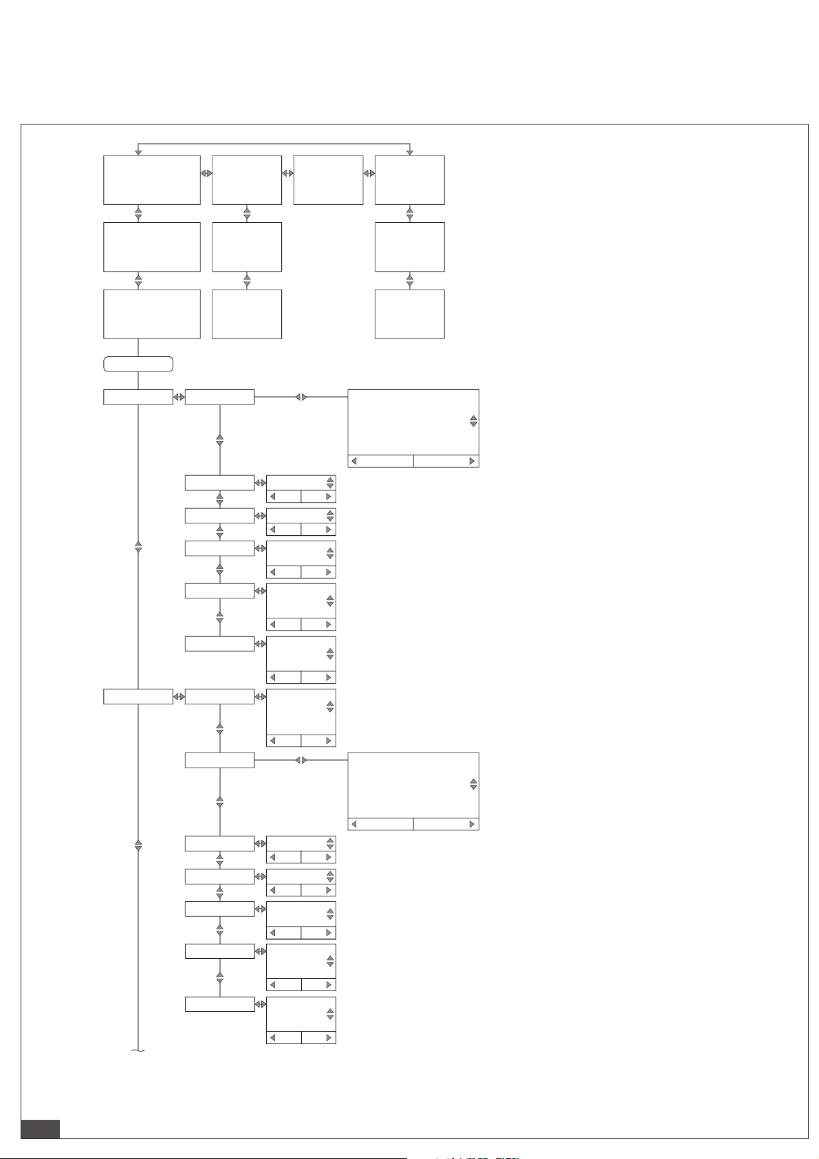
8/1
AVENTICS | AF2 | R412026496–BAL–001–AA | Svenska 77
14 Meny-översikt
IO-länk
Screen 1.1
(Kg/h) Display 1 Top
(m/s) Display 1 Btm (m/s)
Screen 1.2
(m³) Display 2 Top
(m³/h) Display 2 Btm
Screen 1.3
(kg) Display 3 Top
(kWh) Display 3 Btm
Hold for menu
Q1 Menu
Screen 2.1
60 min
Screen 2.2
24h
Screen 2.3
7days
Mode
SetPoint 1
SetPoint 2
Polarity
Simulate
DriverType
FunctionQ2 Menu Switch
Mode
SetPoint 1
SetPoint 2
Polarity
Simulate
DriverType
## # (unit)
abort
## # (unit)
abort
NormallyOpen
NormallyClosed
abort
Normal
Active
Inactive
abort
DRV
PNP
NPN
abort
Frequency
Pulse
Analog
abort
## # (unit)
abort
## # (unit)
abort
NormallyOpen
NormallyClosed
abort
Normal
Active
Inactive
abort
DRV
PNP
NPN
abort
Events
store
store
store
store
store
store
store
store
store
store
store
Status Signal
Info
Signal Quality
Info
Serial No.
Firmware
Switch Hyst Volumetric Flowrate
Switch Hyst Temperature
Switch Hyst Pressure
Switch Window Temperature
Switch Window Pressure
Switch Window Volumetric Flowrate
abort
Switch Hyst Volumetric Flowrate
Switch Hyst Temperature
Switch Hyst Pressure
Switch Window Temperature
Switch Window Pressure
Switch Window Volumetric Flowrate
abort
store
store
Page 85

8/2
AVENTICS | AF2 | R412026496–BAL–001–AA | Svenska 78
ModeQa Menu
High
Low
Polarity
Fail
Simulate
## # (unit)
abort
## # (unit)
abort
Normal
Inverted
abort
3.5 mA
21.5 mA
abort
SimO
3.5 mA
3.8 mA
4.0 mA
10.0 mA
12.0 mA
18.0 mA
20.0 mA
20.5 mA
21.5 mA
abort
store
store
store
store
store
UnitsDisplay MassFlowRat kg / h
FlowVelocity
Volume m
VolFlowRate
4 ... 20 mA Volumetric Flow Range
4 ... 20 mA Temperature
4 ... 20 mA Pressure
kg / min
g / s
m / s
fps
ft³
L
m
3
ft
3
ft
L / min
L / s
m
Mass kg
Energy kWh
Temperature
Pressure
Pages
°C
°F
bar
psi
Disp1 Top
Disp1 Btm
Disp2 Top
abort
abort
abort
3
abort
3
/ h
/ min
/ s
3
/ min
abort
abort
abort
abort
abort
store
store
store
store
store
store
store
store
store
MassFlowRate
Pressure
Temperature
Energy
Mass
VolumetricFlowRate
Volume
FlowVelocity
Disp2 Btm
Disp3 Top
Disp3 Btm
Disp History
abort
store
Page 86

8/3
AVENTICS | AF2 | R412026496–BAL–001–AA | Svenska 79
Simulate
Measure
Rotation 0°
ScreenSaver O
AutoOO O
Brightness 40 %
DisplayPin #_#_#_#
Flow
Temperature
Pressure
90°
180°
270°
abort
1 min
2 min
5 min
10 min
30 min
60 min
abort
1 min
2 min
5 min
10 min
30 min
60 min
abort
60 %
80 %
100 %
abort
abort
SimO
0 % ... 100 %
abort
SimO
0 % ... 100 %
abort
SimO
0 % ... 100 %
abort
Temperature
Pressure
SigQuality
store
store
store
store
store
store
store
store
Filter
Oset
Filter
SigQua2 ### %
SigQua3 ### %
SigQua4
OFF
100 ms
200 ms
500 ms
1 s
2 s
5 s
10 s
abort
##.#°[P]
abort
OFF
100 ms
200 ms
500 ms
1 s
2 s
5 s
10 s
abort
### % SigQua1
(read only)
abort
(read only)
abort
(read only)
abort
### %
(read only)
abort
store
store
store
store
store
store
store
MediumFlow
RefPress ## # bar
0-FlowO
0-FlowCut
Filter
Mode Standard
Air
Argon
Helium
CO2
Nitrogen
abort
abort
## #
abort
## ##
abort
OFF
100 ms
200 ms
500 ms
1 s
2 s
5 s
10 s
abort
(read only)
abort
store
store
store
store
store
store
8778OSIRefCond
User Defined
ISO2533
ISO1217
DIN1945-1
DIN1343
ISO6358
abort
store
Page 87

History
60 min Dynamic charts:
MassFlowRate
Pressure
Temperature
Energy
Mass
VolumetricFlowRate
Volume
FlowVelocity
abort
store
24 hours
7 days
Statistics
View max, mean, min values:
MassFlowRate
Pressure
Temperature
VolumetricFlowRate
FlowVelocity
abort
store
LastReset
(read only)
Reset (action required)
abort
store
Counter
Energy (read only)
LastReset
(read only)
Reset
(action required)
abort
store
Volume (read only)
Mass (read only)
System
Service #_#_#_#
abort
store
FactRes et (action required)
abort
store
SerialNumber
(read only)
DevTag ###
abort
store
AppTag
###
abort
store
FWVersion
(read only)
BLVersion
(read only)
HWVersion
(read only)
8/4
AVENTICS | AF2 | R412026496–BAL–001–AA | Svenska 80
Page 88

9/1
AVENTICS | AF2 | R412026496–BAL–001–AA | Svenska 81
Meny-översikt
Ethernet
Screen 1.1
(Kg/h) Display 1 Top
(m/s) Display 1 Btm (m/s)
Screen 1.2
(m³) Display 2 Top
(m³/h) Display 2 Btm
Screen 1.3
(kg) Display 3 Top
(kWh) Display 3 Btm
Hold for menu
Screen 2.1
60 min
Screen 2.2
24h
Screen 2.3
7days
DHCP ModeEthernet
IP Address
SubNetMask
Gateway
Name ### ### ### ###
StateWebserver
Port
ResetPW
StateOPC UA
Port #####
User # ... #
Password # ... #
StateMQTT Active
Broker
Port
Topic
User
Password
Events
Static IP
DHPC Client
abort
store
### ### ### ###
abort
### ### ### ###
abort
### ### ### ###
abort
abort
Active
Inactive
abort
store
#####
abort
store
(action required)
abort
store
Active
Inactive
abort
store
abort
store
abort
store
abort
store
Inactive
abort
store
### ### ### ###
abort
#####
abort
store
######/#/####
abort
######
abort
store
######
abort
store
store
store
store
store
store
store
Status Signal
Info
Signal Quality
Info
Serial No.
Firmware
Page 89

9/2
AVENTICS | AF2 | R412026496–BAL–001–AA | Svenska 82
Update ##### ms
abort
store
QoS QoS0
QoS1
QoS2
abort
UnitSend
store
Active
Inactive
abort
MassFlowRate
Active
Inactive
abort
FlowVelocity
Active
Inactive
abort
VolFlowRate
Active
Inactive
abort
Volume
Active
Inactive
abort
Mass
Active
Inactive
abort
Energy
Active
Inactive
abort
Temperature
Active
Inactive
abort
Pressure
Active
Inactive
abort
AdditInfos
Active
Inactive
abort
AdditInfos
Active
Inactive
abort
UnitsDisplay MassFlowRate kg / h
kg / min
g / s
abort
FlowVelocity
m / s
fps
abort
Volume m
3
ft³
L
abort
3
/ h
VolFlowRate
m
3
ft
/ min
3
/ s
ft
L / min
L / s
3
m
/ min
abort
Mass
kg
abort
Energy
kWh
abort
Temperature
°C
°F
abort
store
store
store
store
store
store
store
store
store
store
store
store
store
store
store
store
store
store
Page 90

9/3
AVENTICS | AF2 | R412026496–BAL–001–AA | Svenska 83
Simulate
Pressure
Rotation 0°
ScreenSaver O
AutoO O
Brightness
DisplayPin
Flow
Temperature
Pressure
90°
180°
270°
abort
10 s
30 s
60 s
abort
10 s
30 s
60 s
abort
40 %
60 %
80 %
100 %
abort
#_#_#_#
abort
SimO
0 % ... 100 %
abort
SimO
0 % ... 100 %
abort
SimO
0 % ... 100 %
abort
bar
psi
abort
store
MassFlowRateDisp Top1Pages
Pressure
Temperature
Disp1 Btm
Disp2 Top
Disp2 Btm
Disp3 Top
Disp3 Btm
Disp History
store
1 s
2 s
5 s
store
1 s
2 s
5 s
store
store
store
store
store
store
Energy
Mass
VolumetricFlowRate
Volum e
FlowVelocity
abort
store
Page 91

Measure MediumFlow
Air
Argon
Helium
CO2
Nitrogen
abort
store
8778OSIdnoCfeR
User Defined
ISO2533
ISO1217
DIN1945-1
DIN1343
ISO6358
abort
store
0-FlowO
abort
store
0-FlowCut
## #
## ##
abort
store
Filter
OFF
100 ms
200 ms
500 ms
1 s
2 s
5 s
10 s
abort
store
Mode Standard
(read only)
abort
store
Temperature
OFF
100 ms
200 ms
500 ms
1 s
2 s
5 s
10 s
abort
store
Pressure
Filter
Oset
Filter OFF
100 ms
200 ms
500 ms
1 s
2 s
5 s
10 s
abort
store
##.#°[P]
abort
store
SigQuality SigQua1 ### %
(read only)
abort
store
SigQua2
(read only)
abort
store
SigQua3
### %
### %
(read only)
abort
store
SigQua4 ### %
(read only)
abort
store
History 60 min Dynamic charts:
MassFlowRate
Pressure
Temperature
Energy
Mass
VolumetricFlowRate
Volume
FlowVelocity
abort
store
24 hours
7 days
Statistics View max, mean, min values:
MassFlowRate
Pressure
Temperature
VolumetricFlowRate
FlowVelocity
abort
store
LastReset
(read only)
Reset (action required)
abort
store
Counter
Energy (read only)
LastReset
(read only)
Reset (action required)
(action required)
abort
store
Volume (read only)
Mass (read only)
RefPress ## # bar
abort
store
System Service
abort
store
FactReset
abort
store
SerialNumber
(read only)
DevTag
#_#_#_#
###
abort
store
AppTag
###
abort
store
FWVersion
(read only)
BLVersion
(read only)
HWVersion
(read only)
9/4
AVENTICS | AF2 | R412026496–BAL–001–AA | Svenska 84
Page 92

AVENTICS GmbH
Ulmer Straße 4
30880 Laatzen, GERMANY
Phone: +49 (0) 511-21 36-0
Fax: +49 (0) 511-21 36-269
www.aventics.com
Aventics@emerson.com
Further addresses:
www.aventics.com/contact
The data specified above only serve to
describe the product. No statements
concerning a certain condit ion or suitability
for a certain application can be derived
from our information. The given
information does not release the user from
the obligation of own judgement and
verification. It must be remembered that
our products are subject to a natural
process of wear and aging.
An example configuration is depicted on
the title page. The delivered product may
thus vary from that in the illustration.
Translation of the original operating
instructions. The original operating
instructions were created in the German
language.
R412026496–BAL–001–AA/2019-07
Subject to modifications. © All rights
reserved by AVENTICS GmbH, even and
especially in cases of proprietary rights
applications. It may not be reproduced or
given to third parties without its consent.
 Loading...