

AVENTICS Instrucciones de servicio: Descripción del sistema Drive & Diagnostic Link (DDL), Istruzioni per l'uso: Descrizione del sistema Drive & Diagnostic Link (DDL), Notice d’instruction: Description du système Drive & Diagnostic Link (DDL), Bedienungsanleitung: Systembeschreibung Drive & Diagnostic Link (DDL), Bruksanvisning: Systembeskrivning Drive & Diagnostic Link (DDL) Manuals & Guides [sv]
Page 1
Operating instructions
System description Drive & Diagnostic Link
DDL
R499050031/2016-12, Replaces: 08.2014, EN
English
Page 2

Page 3

AVENTICS | DDL | R499050031–BAL–001–AH 3
Contents
Contents
1 Safety Precautions ........................................................ 9
2 DDL General ................................................................. 11
2.1 DDL System Overview........................................................... 11
2.2 DDL Addressing ...................................................................... 12
2.2.1 Manual Addressing .............................................................. 13
2.2.2 Automatic Addressing ......................................................... 13
2.2.3 Error Upon Addressing ....................................................... 14
2.3 DDL Diagnosis ......................................................................... 15
2.4 DDL Data ................................................................................... 15
2.4.1 DDL Connection ..................................................................... 15
2.4.2 DDL Cable Length ................................................................. 16
2.4.3 DDL Cycle Times ................................................................... 16
2.4.4 Standards ............................................................................... 17
3 Bus Coupler ................................................................. 17
3.1 PROFIBUS DP 337 500 025 0/337 500 026 0 ................ 18
3.1.1 Overview .................................................................................. 18
3.1.2 Master Module ....................................................................... 19
3.1.3 Slave Module .......................................................................... 26
3.1.4 Connectors ............................................................................. 32
3.1.5 Technical Data ....................................................................... 35
3.1.6 Dimensions ............................................................................. 36
3.1.7 ATEX-Relevant Information ............................................... 37
3.2 DeviceNet R412006999/R412006998.............................. 37
3.2.1 Overview .................................................................................. 37
3.2.2 Master Module ....................................................................... 38
3.2.3 Slave Module .......................................................................... 43
3.2.4 Connectors ............................................................................. 48
3.2.5 Technical Data ....................................................................... 50
3.2.6 Dimensions ............................................................................. 51
3.2.7 ATEX-Relevant Information ............................................... 52
3.3 Interbus S 337 500 045 0/337 500 046 0 ....................... 52
3.3.1 Overview .................................................................................. 52
3.3.2 Master Module ....................................................................... 54
3.3.3 Slave Module .......................................................................... 65
3.3.4 Connectors ............................................................................. 70
3.3.5 Technical Data ....................................................................... 72
English
Page 4

4 AVENTICS | DDL | R499050031–BAL–001–AH
Contents
3.3.6 Dimensions ............................................................................. 73
3.3.7 ATEX-Relevant Information ............................................... 74
3.4 ControlNet 337 500 056 0 .................................................... 74
3.4.1 Overview .................................................................................. 74
3.4.2 Master Module ....................................................................... 75
3.4.3 Slave Module .......................................................................... 80
3.4.4 Connections ............................................................................ 85
3.4.5 Technical Data ....................................................................... 87
3.4.6 Dimensions ............................................................................. 88
3.5 CANopen R412008000/R412008002................................ 89
3.5.1 Overview .................................................................................. 89
3.5.2 Master Module ....................................................................... 90
3.5.3 Slave Module .......................................................................... 95
3.5.4 Connectors ........................................................................... 101
3.5.5 Technical Data ..................................................................... 103
3.5.6 Dimensions ........................................................................... 104
3.5.7 ATEX-Relevant Information ............................................. 105
3.6 ATEX-Relevant Information for Bus Couplers..............105
3.6.1 Ex-Relevant Excerpt from the Operating Instructions
for S-Design Bus Couplers .............................................. 105
4 DDL Participants ....................................................... 111
4.1 Valve Driver 337 500 005 0/337 500 015 0.................. 111
4.1.1 Overview ................................................................................ 111
4.1.2 DDL Address ........................................................................ 112
4.1.3 DDL Mode .............................................................................. 112
4.1.4 Output Data Length ............................................................ 112
4.1.5 Output Data Range in the Control .................................. 113
4.1.6 Diagnosis ............................................................................... 114
4.1.7 Parameter ............................................................................. 116
4.1.8 Connections .......................................................................... 117
4.1.9 Technical Data ..................................................................... 119
4.1.10 Dimensions ........................................................................... 120
4.2 Valve Driver V-Design
1 827 030 189 0/1 827 030 190 0 ...................................120
4.2.1 Overview ................................................................................ 121
4.2.2 DDL Address ........................................................................ 121
4.2.3 DDL Mode .............................................................................. 121
4.2.4 Output Data Length ............................................................ 122
Page 5

AVENTICS | DDL | R499050031–BAL–001–AH 5
Contents
4.2.5 Output Data Range in the Control .................................. 122
4.2.6 Diagnosis ............................................................................... 123
4.2.7 Parameter ............................................................................. 126
4.2.8 Connections .......................................................................... 127
4.2.9 Technical Data ..................................................................... 130
4.2.10 Dimensions ........................................................................... 131
4.3 Valve System LP04 .............................................................. 131
4.3.1 Overview ................................................................................ 132
4.3.2 DDL address ......................................................................... 132
4.3.3 DDL Mode .............................................................................. 133
4.3.4 Output Data Length ............................................................ 133
4.3.5 Output Data Range in the Control .................................. 133
4.3.6 Diagnosis ............................................................................... 134
4.3.7 Parameter ............................................................................. 137
4.3.8 Connections .......................................................................... 138
4.3.9 Technical Data ..................................................................... 139
4.3.10 Dimensions ........................................................................... 140
4.3.11 Extension for LP04 Valve System with Inputs ........... 141
4.4 Pressure Control Valve ED05 561 014 155 0...............145
4.4.1 Overview ................................................................................ 146
4.4.2 DDL Address ........................................................................ 146
4.4.3 DDL Mode .............................................................................. 147
4.4.4 Data Format ......................................................................... 147
4.4.5 Diagnosis ............................................................................... 149
4.4.6 Parameter ............................................................................. 150
4.4.7 Controller .............................................................................. 150
4.4.8 Connections .......................................................................... 151
4.4.9 Technical Data ..................................................................... 153
4.4.10 Dimensions ........................................................................... 154
4.5 Digital Input Module 337 500 200 0 ................................154
4.5.1 Overview ................................................................................ 155
4.5.2 DDL Address ........................................................................ 155
4.5.3 DDL Mode and Data Length ............................................. 156
4.5.4 Input Data Range in the Control ..................................... 156
4.5.5 Diagnosis ............................................................................... 157
4.5.6 Overload Protection and Parameter ............................. 158
4.5.7 Connections .......................................................................... 159
4.5.8 Technical Data ..................................................................... 160
English
Page 6

6 AVENTICS | DDL | R499050031–BAL–001–AH
Contents
4.5.9 Dimensions ........................................................................... 161
4.5.10 ATEX-Relevant Information ............................................. 161
4.6 Digital Output Module 337 500 202 0 .............................162
4.6.1 Overview ................................................................................ 163
4.6.2 DDL Address ........................................................................ 164
4.6.3 DDL Mode .............................................................................. 164
4.6.4 Output Data Range in the Control .................................. 164
4.6.5 Diagnosis ............................................................................... 165
4.6.6 Parameter ............................................................................. 167
4.6.7 Connections .......................................................................... 168
4.6.8 Technical Data ..................................................................... 170
4.6.9 Dimensions ........................................................................... 171
4.6.10 ATEX-Relevant Information ............................................. 172
4.7 Digital In/Output Module R412006712........................... 172
4.7.1 Overview ................................................................................ 173
4.7.2 DDL Address ........................................................................ 173
4.7.3 DDL Mode and Data Length ............................................. 174
4.7.4 Data Range in the Control ................................................ 174
4.7.5 Diagnosis ............................................................................... 176
4.7.6 Parameter ............................................................................. 179
4.7.7 Connections .......................................................................... 180
4.7.8 Technical Data ..................................................................... 182
4.7.9 Dimensions ........................................................................... 183
4.7.10 ATEX-Relevant Information ............................................. 183
4.8 ATEX-Relevant Information for I/O Modules ................184
4.8.1 Ex-Relevant Excerpt from the Operating Instructions
for I/O Modules .................................................................... 184
5 DDL Accessories ....................................................... 190
5.1 Cables....................................................................................... 190
5.1.1 DDL Cable ............................................................................. 190
5.1.2 Sensor Cables ...................................................................... 190
5.2 Plugs......................................................................................... 191
5.2.1 Terminating Plugs .............................................................. 191
5.2.2 Data Plugs ............................................................................. 191
5.2.3 Power Supply Plugs ........................................................... 191
5.2.4 Other Connectors ................................................................ 192
5.3 Subplates (for Pressure Control Valves) .......................192
5.3.1 Pressure Control Valve ED05 .......................................... 192
Page 7

AVENTICS | DDL | R499050031–BAL–001–AH 7
Contents
5.3.2 Pressure Control Valve ED07 .......................................... 193
6 List of Abbreviations ................................................. 193
7 Declaration of Conformity (ATEX) ............................ 194
7.1 Bus Coupler (3375000250, 3375000450,
R412006999, R412008000)...............................................194
7.2 DDL Input and Output Modules (33750020x0,
R412006712).......................................................................... 194
English
Page 8

8 AVENTICS | DDL | R499050031–BAL–001–AH
Contents
Page 9

AVENTICS | DDL | R499050031–BAL–001–AH 9
Safety Precautions
1 Safety Precautions
W Please pay attention to the general safety instructions and
notice the content of the user manual, before you install,
start up, put pressure or electrical power to the devices.
W The devices should be used only in areas and systems they
are specified for and also comply with the tolerances of the
technical data. In case of non compliance and upon
exceeding the limits, which are mentioned under the point:
technical data, the danger of overheating can be caused as
well as damage to the device, interference in the function
and/or the electrical security.
W The AVENTICS devices have been generally developed to be
used within the industrial sector. If devices shall be used in
living quarters (living and business and industry sector) a
special permission has to be procured from the licensing
authority. In Germany licences are issued by the
Regulierungsbehörde für Telekommunikation und Post
(RegTP).
W To observe the technical data you should only use cables
and wires, being mentioned in the user manual or quotation
drawing.
W The devices have to be grounded according to the
instructions. The relevant DIN/VDE standards or the country
specific standards have to be observed upon installation.
Note especially:
- VDE 0160 (EN 50178)
- VDE 0100
W The supply voltage has to be applied from a powerpack with
protective separation according to EN 60742, classification
VDE 0551. Please pay attention that the external fuse of the
devices is in accordance with the description.
W A faultless and safe operation of the devices requires an
appropriate transport, storage, installation and start up.
W The devices have to be opened only by qualified staff.
Electrostatic accidentally dangerous parts.
English
Page 10

10 AVENTICS | DDL | R499050031–BAL–001–AH
Safety Precautions
W The installation of the devices has to be effected only by
qualified staff and without power supply and pressure.
Please observe the installation position, mentioned in the
user manual.
W To avoid dangerous movements, the electrical start up has
to be made on in depressurized state.
W Start up the device only after installation and tests have
been completely finished.
W Plugs must not be plugged or unplugged under voltage.
To avoid electrical damage to the device, switch off the
power supply before plugs are plugged/unplugged.
W To achieve the protection class and function all seals have to
be intact and fit in correct position.
W The protection class can only be achieved if all unused plugs
are sealed with covers or endplugs.
W Switches and configuration must not be changed during
operation. Changed settings only become valid after power
recycle.
W No equalizing currents due to potential differences must run
via the shield, otherwise the earthing have to be made via
separate wires.
W Use in explosive Area:
Some DDL participants can be used in explosive areas. For
these certified devices at the end of the corresponding
chapter important notes can be found. If the devices are
used in explosive areas, these notes have to be read and
attention has to be paid.
W Further safety precautions in the user manual have to be
followed.
W We refuse all liability for nonobservance of these notes, for
handling of the device or use in an improper way.
Furthermore the guarantee on our devices and accessories
expires.
Page 11

AVENTICS | DDL | R499050031–BAL–001–AH 11
DDL General
2 DDL General
The Drive & Diagnostic Link (DDL) from AVENTICS is a system to
use solenoids, pressure control valves and digital and analog
I/O modules with different field bus systems. Independent from
the used field bus, the systems can be projected and with the
corresponding bus coupler connected to common field busses
like PROFIBUS DP, Interbus S, ControlNet and DeviceNet. DDL
provides, independent from fieldbus, 128 inputs and 128
outputs per bus coupler. For the reason of the transfer mode
system, there is a high data security which is even increased by
the diagnostic functionality. In this way the DDL participants and
the supply voltages are controlled and reported to the
diagnostics. Furthermore the coils of valve units are observed
according to open load and short circuit. Therefore errors can
be quickly recorded up to the affected valve and measures
initiated. In addition some DDL participants offer the possibility
to determine via parameter the reaction upon failure of fieldbus
and DDL. On the basis of the employment of M12 connectors the
connection is very simple and safe. A total length of the cable of
40 m is permitted and offers a high flexibility with the DDL. Here
the gap between the modules is regardless. Because of the high
modularity most of the AVENTICS valve families can be
employed with DDL.
English
2.1 DDL System Overview
Basically the DDL consists of two types of participants:
W The bus coupler makes it possible to transfer data between
the fieldbus system (PROFIBUS DP, Interbus S, DeviceNet, ...)
and the DDL. The bus coupler is therefore the DDL master
and has to be existent once.
W The DDL participant is therefore the slave within the DDL
system. Up to 14 participants can be connected to the DDL.
Page 12

12 AVENTICS | DDL | R499050031–BAL–001–AH
DDL General
The bus coupler with drivers contains, in addition to the Master
module, which is the real bus coupler, also a Slave module
which represents the DDL participant. This Slave module is
therefore a DDL participant and up to 13 other DDL participants
can be connected.
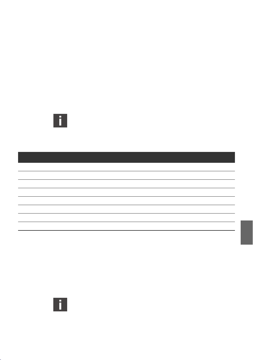
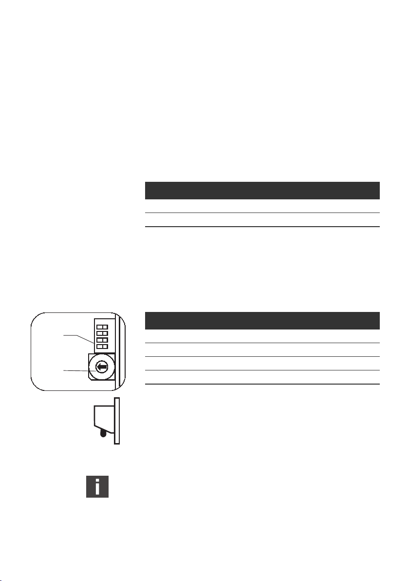
2.2 DDL Addressing
In the DDL system a definite address has to be assigned to each
participant (except for the Master module of the bus coupler).
This is effected via a hex rotary switch at the devices.
Table 1: DDL address switch
Position of Switch Meaning
0 automatic addressing
1 DDL address 1
2 DDL address 2
3 DDL address 3
4 DDL address 4
5 DDL address 5
6 DDL address 6
7 DDL address 7
8 DDL address 8
9 DDL address 9
A DDL address 10
B DDL address 11
C DDL address 12
D DDL address 13
E DDL address 14
F no function
The addressing can be effected in two different ways:
1. Manual addressing
2. Automatic addressing
Page 13

AVENTICS | DDL | R499050031–BAL–001–AH 13
Manual and automatic addressing cannot be effected at the
same time.
Please take into consideration that upon effecting the address
adjustments, changes will only be taken over after a reset of
voltage.
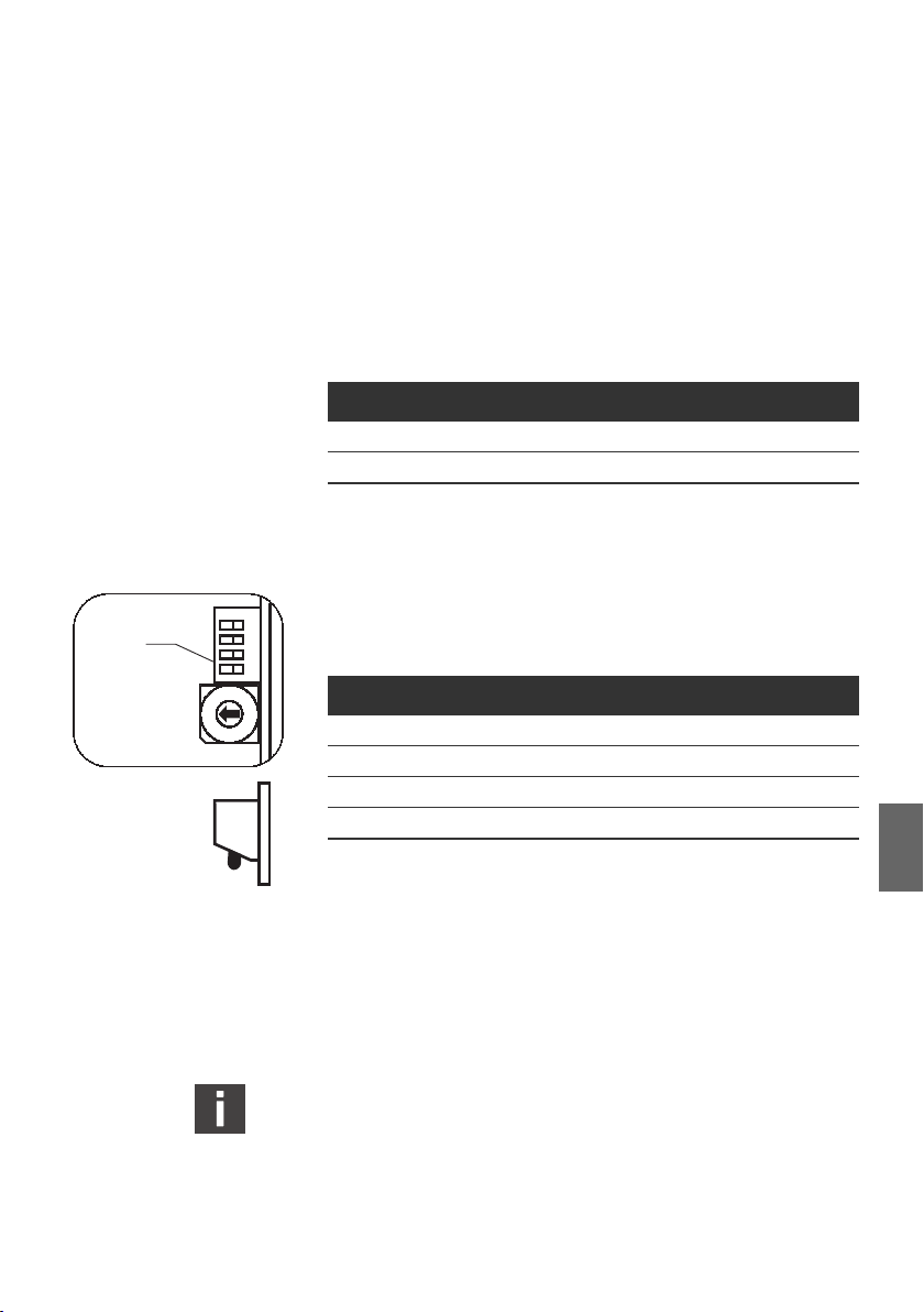
2.2.1 Manual Addressing
A definite address, between 1 and 14, is allocated to each
participant. No participant must have the address 0.
Furthermore the lowest address must be 1 and there must not
be any gaps between the addresses. The addressing is,
however, independent from the physical position of the
participant in the DDL and its type.
Example: 5 DDL participants are connected to a bus coupler
Stand alone (needs no DDL address).
Table 2: Example for manual DDL addressing
Correct: Incorrect: Gap (4) and
lowest address 1
DDL General
Incorrect:
Address 0 is used
DDL
Address
1 pressure control
2 valve driver 3 valve driver 1 valve driver
3 valve driver 5 valve driver 2 valve driver
4 input module 6 input module 3 input module
5 output module 7 output module 4 output module
DDL Node DDL
Address
2 pressure control
valve
DDL Node DDL
Address
0 pressure control
valve
DDL Node
valve
2.2.2 Automatic Addressing
If there is only one participant per type in the DDL system, the
DDL can automatically address itself. For this the address 0 has
to be allocated to all DDL participants. In this case the DDL
system allocates the address automatically to the participants.
The following table shows, what kinds of module types are
available and where to find them in the data and the diagnosis
range.
English
Page 14

14 AVENTICS | DDL | R499050031–BAL–001–AH
DDL General
If not all module types are used, the following modules move up.
If the automatic addressing is used, addresses between 1 ... 14
must not be used.
Table 3: Data range at automatic DDL addressing
Output
Data
Position
1 EP pressure
2 valve driver – valve driver 1 EP pressure control
– input module 2 input module 2 valve driver
3 output module – output module 3 input module
1)
4
– – – – 5 combi module
1)
only, if input or output data are configured.
DDL Node Type Input
control valve
combi module 3
Data
Position
1 EP pressure
1)
DDL Node Type Diagnosis
Data
Position
BC bus coupler
control valve
combi module 4 output module
DDL Node Type
valve
2.2.3 Error Upon Addressing
In order that the DDL is able to recognize and control all
participants, the above mentioned regulations have to be
observed. If the DDL has not been addressed correctly, this will
be indicated by the participant’s red DDL LED. If two participants
have the same address, this cannot be recognized that safely
that the DDL gets not into Run mode. This type of wrong
addressing can be recognized by checking the number of
livebits. In case of a DDL communication diagnosis, the
addressing of all participants shall be checked. Furthermore
the same baud rate has to be adjusted with all participants, also
with the Master module. In addition it has to be checked that all
cables have been correctly connected. Upon problems with very
long cables we recommend to run the DDL with 125 kBaud. For
further information on the baud rate adjustments, please refer
to the description of the device.
Page 15

AVENTICS | DDL | R499050031–BAL–001–AH 15
DDL General
2.3 DDL Diagnosis
The DDL participants/bus couplers have two kinds of diagnosis.
On the one hand, each DDL device has LEDs to indicate the
diagnosis visually. On the other hand the DDL participants send
diagnosis data via the DDL to the bus coupler, which transmits
its own data and the diagnosis data of the DDL participants to
the control. The meaning of the diagnosis data and further
information can be taken from the corresponding chapters. The
DDL communication respectively the availability of the DDL
participants is constantly controlled by the bus coupler. As soon
as all configured DDL participants exist and communicate, the
red DDL LED turns off. If a participant does not communicate
any more, the red DDL LED will light at the corresponding
participant and the bus coupler reports the interference. In
addition the corresponding livebit and the DDL LED at the bus
coupler (Master module) lights (if existing). The communication
to the other DDL participants will however be maintained. If the
bus coupler recognizes the recurring participant (DDL LED at
the participant will go off), that way the configuration will be all
right, the DDL LED at the bus coupler will also go off.
In order to initialize the system correctly, the valves must not be
controlled. All supply voltages must exist correspondingly.
2.4 DDL Data
2.4.1 DDL Connection
The connection of the DDL is effected via 5 pin M12x1 plugs.
5-wire, shielded lines have to be used as connecting cables. The
shield has to be connected to the thread of the plug. The
diameter of the wires is 0.34 mm
connection is performed by a mounting male plug and the DDL
OUT connection as mounting female plug at the DDL
participants. As DDL participants can be damaged if 24 V are
applied to the signal line DDL H and DDL L or the supply lines
have been exchanged, we recommend to use pre fabricated and
2
minimum. The DDL IN
English
Page 16

16 AVENTICS | DDL | R499050031–BAL–001–AH
DDL General
examined wiring. This is also mentioned in chapter 5 “DDL
Accessories“.
2
1
5
4
3
Fig. 1: DDL connection
1 Pin 1 = 24 V electronics 4 Pin 4 = DDL H
2 Pin 2 = 24 V valves 5 Pin 5 = DDL L
3 Pin 3 = 0 V
2.4.2 DDL Cable Length
The total cable length of DDL system is limited to 40 m. Thereby
it is irrelevant, whether the length between the two participants
will be used or distributed equally.
With great cable length and great consumption of electricity, the
voltage drop over the cables can provoke, that the supply
voltages at the DDL participants fall below the respective
tolerance limits. In such cases the DDL valve drivers can be
used with an external power supply (337 500 015 0 or
1 827 030 190 0), which, because of the additional supply,
indicate the voltage supply level.
2.4.3 DDL Cycle Times
DDL is constructed for a fast and secure data transfer. The DDL
cycle times depend on several parameters. In that way the baud
rate, number of participants and configured in and output data
length (max. 128 bit) have influence on the cycle time.
In table 4 some applications and the corresponding DDL cycle
times are shown.
The process times in the bus coupler (approx. 0.8 ms) and the
cycle time of the field bus are not included in this overview. The
cycle time can be seen as an average value. With an ideal data
transmission the signal can be transmitted considerably earlier.
With critical applications it should be taken into consideration
that with an unfavorable data transmission it could take a cycle
time twice as long, until the signals are output or transmitted to
the field bus.
Page 17

AVENTICS | DDL | R499050031–BAL–001–AH 17
Bus Coupler
Table 4: Examples for DDL cycle times with different DDL configurations
Example DDL Baud rates DDL Participants DDL Data length I/O DDL Cycletime
1 250 kBaud 2 0/32 3.0 ms
2 250 kBaud 5 128/128 7.0 ms
3 250 kBaud 14 128/128 14.0 ms
4 125 kBaud 2 0/16 4.2 ms
5 125 kBaud 5 128/128 13.0 ms
2.4.4 Standards
The DDL system fulfills the standards for EMC, listed below:
W EN 61000-6-4
W EN 61000-6-2
3 Bus Coupler
AVENTICS bus couplers allow to connect pressure control
valves, valve units and digital and analog in and output modules
to a programmable logic control (PLC) by using a field bus
system like PROFIBUS DP, Interbus S, ControlNet, DeviceNet,
CANopen,... . One advantage of a serial control is the saving of
the parallel output cards in the PLC as well as the necessary
wiring. Another one is the possibility to transfer further
information like Diagnosis and parameters.
Bus couplers are available in two different designs. On the one
hand there is the Stand alone module. It consists only of the
Master module. The Master module communicates with the
field bus system and controls the DDL. On the other hand bus
couplers with drivers to control the valve via a 25 pin D-Sub
plug, are available. They have, in addition to the Master module,
also a Slave module which operates like a single DDL
participant, but is situated within the same housing.
English
Page 18

18 AVENTICS | DDL | R499050031–BAL–001–AH
Bus Coupler
3.1 PROFIBUS DP 337 500 025 0/337 500 026 0
The bus coupler for PROFIBUS DP is available in two different
designs. The bus coupler with drivers (337 500 026 0) can be
directly mounted onto a valve unit. Apart from controlling this
unit, the DDL is also available for other DDL participants.
The bus coupler Stand alone (337 500 025 0) is mounted
separately and offers only the DDL. The parts of description of
the Slave module, do not apply to the bus coupler Stand alone.
Both modules are connected to the PROFIBUS DP via a shielded
2 wire cable.
3.1.1 Overview
PROFIBUS DP
The field bus system PROFIBUS DP which is used for the
communication with the control, is a fast working bus system
for the cyclic exchange of user data. PROFIBUS DP is a master
slave bus system, where 2 master and 122 passive participants
maximum can be connected to. Two designs as transmission
medium are available:
W 2 wire line (shielded)
W optical fibre
For installation information of the networks and for the
configuration of the lines, please refer to the documentation
of the PROFIBUS association. http://www.profibus.com
Page 19

Bus Coupler PROFIBUS DP
1
POWER SUPPLY
2
DDL
STOP
RUN
VALVE
SENSOR
POWER SUPPLY
12141214121412
VALVESENSOR
3
0
1
9
2
8
3
7
9
4
8
7
21
4321
4
6
5
0
1
2
3
4
6
5
9
8
A
7
B
6
C
5
D
4
E
3
F
2
1
0
5
6
Fig. 2: LED and switch of 337 500 026 0
AVENTICS | DDL | R499050031–BAL–001–AH 19
Bus Coupler
7
8
1
9
1 DDL LEDs
2 PROFIBUS LEDs
3 DP address S1
4 DP address S2
6 DDL mode S3
7 DDL mode S4
8 Slave module
9 DDL address S5
5 Master module
3.1.2 Master Module
The Master module is the interface between the PROFIBUS DP
and the DDL. It controls the DDL and monitors the supply
voltages.
PROFIBUS DP Addresses
Before a connection to the PROFIBUS DP System, an address
will have to be assigned to the bus coupler. After opening the
sealing cap, the address is assigned by two rotary switches.
Addresses from 0 ... 99 can be assigned. With switch S1 the ten
digit is set, with S2 the one digit is set. In the factory the devices
are already adjusted to address 3.
English
Page 20

20 AVENTICS | DDL | R499050031–BAL–001–AH
Bus Coupler
The switches must not be changed during operation.
Changed switch positions will only become valid, after the
device has been turned off and restarted.
PROFIBUS DP – Baud Rates
The PROFIBUS transfer rates are adjusted with the PROFIBUS
master (PLC) and are then automatically recognized by the slave
(bus coupler). The following values can be adjusted as rates of
transmission:
9.6 / 19.2 / 93.75 / 187.5 / 500 / 1500 / 3000 / 6000 / 12000 kBaud.
PROFIBUS DP Configuration
For the PLC configuration software, e. g. COM PROFIBUS the
device master file RXP_05EF.gsd will be needed. This file is
included in the delivery or can be ordered separately under the
following no.: 546 046 941 2. The file has to be copied into the
directory which was defined by the PLC configuration software.
On this disk are also two Icon files for this bus coupler
(RX_D05EF.dip/RX_R05EF.dib).
For the configuration of the bus coupler, the type of station bus
coupler has to be selected (above folder Valves/AVENTICS).
After selection of the field "configuration" and modules, the
corresponding DDL modules have to be inserted. Each
participant of the DDL has to be singly configured as a module.
The DDL participant with address 1 has to be configured as
module 0, participant 2 as module 1 etc.
Combi modules need 2 modules, but only one DDL address.
Thereby the number of the module moves one digit per
module towards the DDL address.
Also the length of the data of the valve unit and the input module
must be correctly adjusted. Arbitrary addresses in the address
area of the control can be assigned to each module (if the
control permits this).
If the configuration differs from the real DDL system, the bus
coupler will not be recognized correctly by the PROFIBUS
master!
Page 21
AVENTICS | DDL | R499050031–BAL–001–AH 21
Parameter
These functions are deposited in the GSD file and can be
displayed as plain text via a configuration tool (e.g. COM
PROFIBUS or S7 Hardware configuration). Per each DDL
participant one byte is transferred and also one byte for the bus
coupler. Each single parameter byte for the participants can be
individually adjusted. If no parameters are adjusted, the DDL
participants use their default parameter.
Changed parameters only become valid if the device has been
turned off and on again.
Bus Coupler Parameter
Table 5: Bus coupler parameter
Bit Name of Parameter Bit = 0 Bit = 1
7 reserved
6 reserved
5 reserved
4 reserved
3 reserved
2 reserved
1 diagnosis send to PLC no (default) yes
0 reaction upon PROFIBUS failure values at 0 (default) freeze values
Bus Coupler
Bit 0 = 0 Upon failure of the PROFIBUS DP, the output data in the bus
coupler are set at 0 (default).
Bit 0 = 1 Upon failure of the PROFIBUS DP, the output data in the bus
coupler remain with the last value and the coils will be kept
driven (values frozen).
Upon return of the PROFIBUS communication the outputs
can be set at 0 of short duration.
Bit 1 = 0 No diagnosis data which go beyond the PROFIBUS DP standard
diagnosis are sent to PLC (default).
English
Page 22

22 AVENTICS | DDL | R499050031–BAL–001–AH
Bus Coupler
Bit 1 = 1 User diagnosis data (DDL diagnosis) are send to the PLC via the
PROFIBUS DP.
DDL Participant Parameter
The parameter descriptions of the individual DDL participants
can be taken from the corresponding chapters.
DDL Address
At the Master module respectively. Stand alone bus coupler no
DDL Address has to be set.
For correct function of the DDL (Drive & Diagnostic Link)
following items must be fulfilled.
W same Baud rate at all DDL modules
W DDL Address within 1 ... 14, starting with 1, without gap, no
double used Address
W DDL Address 0: see chapter 2.2 “DDL Addressing“.
DDL Mode
The transmission rate of the DDL is adjusted with the 2 bit DIP
switch S3, next to the PROFIBUS DP address switches at the
forefront. All DDL participants have to be adjusted to the same
transmission rate.
Table 6: DDL baud rate
Bit Open On
1 DDL 125 kBaud DDL 250 kBaud (default)
2 no function no function
Page 23

AVENTICS | DDL | R499050031–BAL–001–AH 23
Bus Coupler
0
1
9
2
8
3
7
4
6
5
0
1
9
2
8
3
7
4
6
5
21
ON OPEN
OPEN
ON
Fig. 3: DIP switch S3:
DDL mode
Table 7: Overview on the LED indications
Description Color of LED Meaning
STOP red lighting bus stop / DDL configuration not ok / Hardware not OK
Run green bus in operation / configuration ok / DATA exchange
SUPPLY
SENSOR
SUPPLY
VALVE
S3
red flashing bus stop / DDL configuration ok / PROFIBUS configuration
green lighting voltage within the tolerance
green flashing voltage below or beyond the tolerance
green off no voltage at connection of sensor supply (X1S, Pin 1)
green lighting voltage within the tolerance
green flashing voltage below or beyond the tolerance
green off no voltage at connection of sensor supply (X1S, Pin 1)
Diagnosis
LED Diagnosis
On the top side of the device LEDs indicate the state of the
PROFIBUS DP interface as well as of the power supply.
meets not the actual DDL configuration
English
Voltage Monitoring The applied voltage is indicated by two green LEDs. The voltages
at plug DDL are indicated. The liminal supply voltage is at
19.2 V/21.6 V for low voltage and at 26.4 V/28.8 V for
overvoltage.
Short Circuit Monitoring The bus coupler has a short circuit monitoring for the DDL. Both
power supplies are monitored independently from each other. If
the short circuit monitoring in the bus coupler starts up, the
corresponding green LED begins to flash.
Page 24

24 AVENTICS | DDL | R499050031–BAL–001–AH
Bus Coupler
Software Diagnosis In case of error, an „EXT_DIAG“ message is send via the
PROFIBUS DP, to the control. The length of the ext. diagnosis
message depends on the number of participants. For the bus
coupler Stand alone 337 500 025 0 the length is 4 byte diagnosis
+ 1 byte header (PROFIBUS Norm). After the bus coupler the
diagnosis for the participants is sorted upwards, according to
the DDL addresses. For each further DDL participant the
commensurate diagnosis bytes are added. The diagnosis length
of a valve driver consists of 1 Byte + the configurated data
length. The Diagnosis data length for other DDL nodes can be
read up on the corresponding chapters.
The bus coupler with drivers (337 500 026 0) behaves like the
Stand alone module and an additional DDL participant for valve
control (see Slave Module).
To use the diagnosis function, the corresponding parameter has
to be adjusted (see table 5, parameter for the bus coupler).
Page 25

AVENTICS | DDL | R499050031–BAL–001–AH 25
Bus Coupler
Table 8: Example: diagnosis fieldbus module PROFIBUS DP with one valve unit incl. standard diagnosis
DDL
gaps
between
or
address 0
and
1
...
14
mixed
DDL
addr.#5
exists
DDL
addr.#13
exists
output
4
output
12
output
20
output
28
Bit
DDL
no units
at DDL
DDL
addr.#4
exists
DDL
addr.#12
exists
output
diagnosis
output
diagnosis
output
diagnosis
output
diagnosis
11
19
27
3
24 V
electronic
input
diagnosis
DDL
addr.#3
exists
DDL
addr.#11
exists
output
2
diagnosis
output
10
diagnosis
output
18
diagnosis
output
26
diagnosis
24 V
valve
voltage at
DDL
output
diagnosis
DDL
addr.#2
exists
DDL
addr.#10
exists
24 V
valve
supply
diagnosis
output
1
diagnosis
output
9
diagnosis
output
17
diagnosis
output
25
diagnosis
24 V
electronic
voltage at
DDL
output
diagnosis
DDL
addr.#1
exists
DDL
addr.#9
exists
24 V
electronic
supply
diagnosis
output
0
diagnosis
output
8
diagnosis
output
16
diagnosis
output
24
diagnosis
Regarding
Byte
0 DP Norm
1 DP Norm
2 DP Norm
3 DP Norm
4 DP Norm
5 DP Norm
6 Headerbyte 0 0 block length in Byte
Bus coupler
7
8 Bus coupler
Bus coupler DDL
9
Bus coupler
10
module with
address 1
11
(valve unit)
module with
12
address 1
(valve unit)
module with
13
address 1
(valve unit)
module with
14
address 1
(valve unit)
module with
15
address 1
(valve unit)
7 6 5 4 3 2 1 0
addresses
––
have been
addr.#8
exists
––
DDL
comm.
diagnosis
output
7
diagnosis
output
15
diagnosis
output
23
diagnosis
output
31
diagnosis
DDL
addr.#7
exists
output
6
diagnosis
output
14
diagnosis
output
22
diagnosis
output
30
diagnosis
DDL
addr.#6
exists
DDL
addr.#14
exists
––––
output
5
diagnosis
output
diagnosis
output
diagnosis
output
diagnosis
diagnosis
13
diagnosis
21
diagnosis
29
diagnosis
English
Page 26

26 AVENTICS | DDL | R499050031–BAL–001–AH
Bus Coupler
Meaning of the
diagnosis bits
W Byte 6:
– Bit 0 ... 5: total length of the diagnosis data in byte
W Byte 7:
– Bit 0: Electronic power supply of succeeding DDL modules
below 19.2 V or beyond 28.8 V
– Bit 1: Valve power supply of succeeding DDL modules
below 21.6 V or beyond 26.4 V
– Bit 2: Power supply of Master module electronics below
19.2 V or beyond 28.8 V
– Bit 3: No external modules connected to DDL
– Bit 4: Gaps between addresses, address 0 and 1 ... 14 have
been mixed up or addresses have been assigned twice.
(It cannot be assured that double addresses are
recognized safely)
W Byte 8:
– free
W Byte 9 + 10:
– Bit 0 ... 7: For each existing address the corresponding bit
will be set.
With automatic addressing the following is valid:
W Byte 9:
– Bit 0: Pressure control valve
– Bit 1: Valve driver
– Bit 2: Input module
– Bit 3: Output module
– Bit 4: Combi module
3.1.3 Slave Module
The Slave module behaves like a DDL participant for valve
control but it is situated within the housing of the bus coupler.
According to this a DDL address and a baud rate have to be
adjusted! The connection to the valve unit is effected via a 25 pin
D-Sub plug at the bottom side of the module.
Page 27
OPEN ON
S4
2
1
0
F
OPEN
Fig. 4: DIP switch S4
AVENTICS | DDL | R499050031–BAL–001–AH 27
Bus Coupler
DDL Address
The DDL address is adjusted with the switch S5. The regulation for
the adjustment can be found in chapter 2.2 “DDL Addressing“.
DDL Mode
The DDL baud rate is adjusted with switch S4. All participants
have to be adjusted to the same baud rate.
Table 9: DDL baud rate
Bit Open On
1 DDL 125 kBaud DDL 250 kBaud (default)
2 no function no function
Output Data Length
With switch S4 the number of outputs is adjusted. With this it is
possible to optimize the needed data range of the control for
43
21
5
4
3
6
7
8
9
A
B
E
C
D
ON
smaller valve units.
Table 10: Data length
Bit 3 Bit 4 Data length
Open Open 1 Byte
On Open 2 Byte
Open On 3 Byte
On On 4 Byte (default)
English
The 4 byte mode offers a conformity with 16 bit PLC systems.
But only the first 3 bytes are transferred to the outputs of the
D-Sub plug.
The switches must not be changed during operation.
Changed switch positions will only become valid, after the
device has been turned off and restarted.
Page 28

28 AVENTICS | DDL | R499050031–BAL–001–AH
Bus Coupler
Output Data Range of the Control
The DDL address determines the position of the output data in
the data range of bus coupler and therefore the position in the
address range of the control. The valve driver occupies,
depending on the length set, 1 ... 4 byte in the output range of the
control. Whereby the 4th byte does not represent real outputs
and serves only for the 16 bit conformity.
Table 11: Output bits
Byte Regarding
valve unit
X
Pin 25 pol.
D-Sub
valve unit
X + 1
Pin 25 pol.
D-Sub
valve unit
X + 2
Pin 25 pol.
D-Sub
valve unit
X + 3
Pin 25 pol.
D-Sub
7 6 5 4 3 2 1 0
output7output6output5output4output3output2output1output
87654321
output15output14output13output12output11output10output9output
16 15 14 13 12 11 10 9
output23output22output21output20output19output18output17output
24 23 22 21 20 19 18 17
not
existent
Nc Nc Nc Nc Nc Nc Nc Nc
not
existent
not
existent
not
existent
Bit
existent
not
not
existent
not
existent
0
8
16
not
existent
At Pin 25 of 25 pol. D-Sub plug 0 V is connected.
If address 0 (automatic addressing) is set, the bus coupler with
driver behaves like a valve driver. Further information can be
taken from chapter 2.2 “DDL Addressing“.
The valve driver does not occupy any data in the input range,
only within the diagnosis range of the DDL.
Byte X is the start address of the output data range of the DDL
participant in the control (see PROFIBUS DP Configuration).
Page 29

LED Diagnosis
AVENTICS | DDL | R499050031–BAL–001–AH 29
Bus Coupler
Diagnosis
Table 12: Overview of the DDL LED indication
Description Color of LED Meaning
SUPPLY
SENSOR
SUPPLY
VALVE
DDL red lighting no DDL communication (see below)
The limits of power supply (electronics/valves) are at 19.2 V/
21.6 V for low voltage and at 28.8/26.4 V for overvoltage. The
voltages are measured at plug DDL OUT.
The LED DDL indicates that no reference data communication
takes place in the DDL system. This can be due to:
W The adjusted baud rate of the DDL modules is not equal
W Gaps in the addressing
W Same address has been assigned for 2 modules
W Address 0 and 1 ... 14 have been assigned at the same time
W Configuration has changed during operation
green lighting voltage within the tolerance
green flashing voltage below or beyond the tolerance
green off no voltage at connection sensor supply
(X1S, Pin 1)
green lighting voltage within the tolerance
green flashing voltage below or beyond the tolerance
green off no voltage at connection sensor supply
(X1S, Pin 1)
Voltage Monitoring The applied voltage supplies are indicated by two green LEDs:
Voltages at the plug DDL are shown. The threshold of the power
supply (electronic/valves) are at 19.2 V/21.6 V for under voltage
and at 28.8 V/26.4 V for overvoltage.
Software Diagnosis The software diagnosis of the Slave module is 1 byte standard
diagnosis + configured data length long.
With bus coupler 337 500 026 0 the outputs from 24 ... 31 are
not really existent. For this reason there is no rational diagnosis.
With smaller valve units further outputs and their diagnosis can
not be used.
The address range of the diagnosis drives from the DDL address.
English
Page 30

30 AVENTICS | DDL | R499050031–BAL–001–AH
Bus Coupler
If address 0 (automatic addressing) is set, the bus coupler with
driver behaves like a valve driver. Further information can be
taken from chapter 2.2 “DDL Addressing“.
Table 13: Diagnosis bits
Byte
Z + 1
Z + 2
Z + 3
Z + 4
Z
7 6 5 4 3 2 1 0
DDL
comm.
diagnosis
output
7
diagnosis
output
15
diagnosis
output
23
diagnosis
output
31
diagnosis
–––––
output
6
diagnosis
output
14
diagnosis
output
22
diagnosis
output
30
diagnosis
output
5
diagnosis
output
13
diagnosis
output
21
diagnosis
output
29
diagnosis
diagnosis
diagnosis
diagnosis
diagnosis
Bit
output
4
output
12
output
20
output
28
output
3
diagnosis
output
11
diagnosis
output
19
diagnosis
output
27
diagnosis
output
2
diagnosis
output
10
diagnosis
output
18
diagnosis
output
26
diagnosis
24 V
valve
supply
diagnosis
output
1
diagnosis
output
9
diagnosis
output
17
diagnosis
output
25
diagnosis
24 V
electronic
supply
diagnosis
output
0
diagnosis
output
8
diagnosis
output
16
diagnosis
output
24
diagnosis
Meaning of the bits W Byte Z Bit 0: Power supply of the electronics below 19.2 V or
beyond 28.8 V
W Byte Z Bit 1: Power supply of the valves below 21.6 V or
beyond 26.4 V
W Byte Z Bit 7: Communication to the DDL module interrupted
W Byte (Z + 1) – (Z + 4) Bit 0 ... 7: Output short circuit or open
(see description of the parameter).
W Byte Z is the start address of the diagnosis range of the DDL
participant in the control.
NOTICE
A short circuit can only be detected if the output is driven. An
open output can only be detected if it is not driven.
Page 31

AVENTICS | DDL | R499050031–BAL–001–AH 31
Bus Coupler
Parameter
The Slave module provides the DDL master module for
PROFIBUS DP with these functions. For each DDL participant
one byte for parameter is available. The parameters are
transferred only with the DDL initialization. Each parameter
byte for the participants can be adjusted individually. In
connection with the PLC the PROFIBUS provides comfortable
possibilities for adjustment. If the control does not provide these
functions, default parameters will be used.
Table 14: Parameter for the Slave module
Bit Parameter Name Bit = 0 Bit = 1
7 reserved
6 reserved
5 reserved
4 reserved
3 reaction at DDL failure values at 0 (default) freeze values
2 reserved
1 diagnosis message of the coils for controlled outputs (default) changes are transferred
0 reserved
Bit 1 = 0 Output based diagnosis messages are only sent, if the output is
controlled. Upon starting the system it is not checked, which
coils do exist. If an output is controlled, where no coil exists, a
diagnosis message is generated.
Bit 1 = 1 Upon starting the system it is first determined what coils do
exist. This information is then transferred via a diagnosis
message to the control. In the control this message can be
compared with a deposited configuration of the system. (This
function is only supported by PROFIBUS DP; with other field bus
systems the diagnosis data are transferred cyclic). Missing coils
can be determined upon the start of the system. During the
cyclic operation only diagnosis messages are sent, if there have
been changes according to this configuration. Thereby the
complete diagnosis range is transferred. Open load is
immediately reported, the valve needs not to be controlled.
English
Page 32

32 AVENTICS | DDL | R499050031–BAL–001–AH
Bus Coupler
Bit 3 = 0 Upon failure of the DDL, the output data are set at 0 in the Slave
module.
Bit 3 = 1 Upon failure of the DDL, the output data are stored in the Slave
module and the coils are still controlled (freezing values).
Changed parameters only become valid, if the device has
been switched off and has been restarted.
3.1.4 Connectors
1 X7P2: PROFIBUS DP Input
2 X7P2: PROFIBUS DP Output
3 XPD: DDL OUT
4 X1S: Power supply
1
5 X2O: Valve driver (only 3375000260)
2
.
Fig. 5: Connectors
3
NOTICE
The connectors must not be plugged or pulled under load.
4
The assembly or the plugging and pulling of the bus coupler
onto the valve driver is only allowed when the device is off
5
circuit!
Power Supply
The power supply is connected via the circular plug X1S. Only
4 pin M12 connecting bushes should be used, where pin 5 is
closed; in order to avoid a mix up with other connections. The
diameter of the wires should be chosen as big as possible, but
at least 0.5 mm
Both power supplies must be secured with external 3 A T fuses.
The maximum allowed voltage in the O V line is limited to 4 A by
the connector.
2
.
Page 33

AVENTICS | DDL | R499050031–BAL–001–AH 33
Bus Coupler
1
4
2 3
Fig. 6: X1S power supply
1 Pin 1: 24 V sensor voltage / electronics
2 Pin 2: 24 V valve voltage
3 Pin 3: 0 V
4 Pin 4: Function earth
The electronics of the bus coupler and the electronics of all
I/O modules and initiators connected to the DDL (with modules
without ext. power supply) are supplied via X1S, pin 1.
If modules without an external power supply are used, the
switching voltage for connected valves must be supplied via
X1S, pin 2.Because of the separate supply of this power supply
it is possible, in an emergency stop situation, only to turn off the
valves, whereas the PLC, the serial interfaces and the initiators
remain in operation. Turning off the power supply for the serial
interface can lead to the state STOP of the PLC.
The 24 V supplies must be effected out of a common power
supply unit respectively with a common O V connection. A
power supply unit with a secure separation according to
EN 60742, classification VDE 0551 should be used.
4
X7P1: OUT
(female)
2
X7P2: IN
(male)
1
5
2 3
Fig. 7: PROFIBUS DP
1
data plug
Data Line PROFIBUS DP
The connection to the PROFIBUS system is done with data plug
M12 5 pin. B coded female at PROFIBUS DP IN (X7P2) or male at
PROFIBUS DP OUT (X7P1). Both connections are connected in
parallel and have the following assignment:
1 Pin 1: 5 V Supply for the connecting plug
3
4
2 Pin 2: A data line
3 Pin 3: 0 V supply voltage for the terminating plug (5 V)
4 Pin 4: B data line
5
5 Pin 5: shield
The connection is in correspondence with the recommendations
of the PROFIBUS association for the allocation of the 5 pin M12
B coded plug.
English
Page 34
34 AVENTICS | DDL | R499050031–BAL–001–AH
Bus Coupler
R
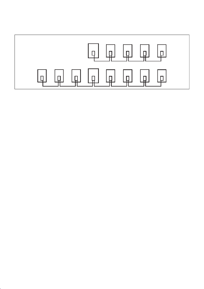
Fig. 8: Possible layout of bus participants
The terminating resistors integrated in the connecting plugs of
the participants marked with a “R” have to be activated or with
the bus coupler, the PROFIBUS DP terminating plug M12,
B coded (see chapter 5 “DDL Accessories“) has to be plugged to
the connector PROFIBUS DP OUT.
There has to be a terminator for the first and also for the last
participant of a bus line (see illustration 8). The termination
resistor is designed for a PROFIBUS DP cable of type A (wave
resistance 135 ... 165 Ω) and integrated into the end plug.
Data Line DDL
The output of the DDL is short circuit protected at all lines.
Nevertheless DDL participants can be damaged if 24 V are
applied to signal lines DDL H and DDL L. For this reason it is
recommend to use pre fabricated cables (see chapter 5 “DDL
Accessories“). The allocation of the DDL connections are
described in chapter 2.4 “DDL Data“.
The DDL end plug (see chapter 5 “DDL Accessories“) is
necessary to guarantee a definite termination of the line and the
protection degree IP 65, if the module is the last or the only
participant of a DDL line.
MASTER
SPS
R
SPS
SLAVE
R
R
Page 35

AVENTICS | DDL | R499050031–BAL–001–AH 35
Bus Coupler
3.1.5 Technical Data
Profibus DP
Technical Data
Operating voltage valves 24 V DC +10 -0 %
Operating voltage initiators and
electronics
Fuse of the valve voltage external 3 A T
Fuse of electronics external 3 A T
Attention: Maximum current
in the 0 V line
Voltage drop, internal 0.8 V
Required power electronics 90 mA
Power supply for sensors max. 3 A per DDL branch
Power supply for valves max. 3 A per DDL branch
Number of output bytes
(only 337 500 026 0)
Run up period after switching on the
power supply
Ambient temperature range +5°C ... +50°C
Stock temperature -20°C ... +70°C
Protection class (with closed connectors) IP 65
Installation position arbitrary
Further technical data s. quotation drawing
* With a current I of max. 2 A per valve and sensor
24 V DC ±20 %
max. 4 A
1 / 2 / 3 / 4 byte
2 s
+5°C ... +40°C (ATEX)
+5°C ... +50°C (ATEX)*
IP 54 (ATEX)
English
Page 36

36 AVENTICS | DDL | R499050031–BAL–001–AH
Bus Coupler
3.1.6 Dimensions
45 107
POWER SUPPLY
VALVE
SENSOR
DDL
STOP
RUN
VALVE
SENSOR
POWER SUPPLY
0
1
9
2
8
3
4321
7
4
6
5
0
1
9
2
8
3
7
4
6
5
9
8
7
A
B
6
C
5
D
4
E
3
F
2
0
1
21
Fig. 9: Dimensions of the bus coupler with drivers (337 500 026 0)
104
113
STOP
RUN
VALVE
SENSOR
POWER SUPPLY
0
1
9
2
8
3
7
4
6
5
0
1
9
2
8
3
7
4
6
5
21
120
140
30
45
Fig. 10: Dimensions of the bus coupler Stand alone (337 500 025 0)
Page 37

AVENTICS | DDL | R499050031–BAL–001–AH 37
Bus Coupler
3.1.7 ATEX-Relevant Information
If the bus coupler PROFIBUS DP 337 500 025 0 is used in zone 2,
attention has to be paid to the following ATEX-relevant
information.
See chapter 3.6.1 “Ex-Relevant Excerpt from the Operating
Instructions for S-Design Bus Couplers“.
3.2 DeviceNet R412006999/R412006998
The bus coupler DDL for DeviceNet is available in two different
designs. The bus coupler with drivers (R412006998) can be
directly mounted onto a valve unit. In addition to the control of
this unit the DDL is also available for other DDL participants.
The bus coupler Stand alone (R412006999) is separately
mounted and provides only the DDL.
Parts of the description concerning the Slave module are not
valid for the bus coupler Stand alone.
3.2.1 Overview
DeviceNet
DeviceNet is a CAN protocol that is based on a definite master/
slave connection. Several masters can share a physical CAN
data line and control several slaves. A slave though is always
dedicated to one master and can only exchange data with this
one. A master must first release a slave before another master
is able to ask for the slave and activate him.
The electronic data sheet (EDS) can be downloaded from the
Internet at www.aventics.com/mediadirectory:
0064000000040205.eds
Type: EDS Configuration File
For information concerning the installation of the network and
regarding the preparation of the line, please refer to the
documentation of the company Rockwell Automation/AllenBradley.
English
Page 38

38 AVENTICS | DDL | R499050031–BAL–001–AH
Bus Coupler
Bus Coupler DeviceNet
1
POWER SUPPLY
2
5 V
RUN
DDL
STATUS
MNS
12141214121412
VALVESENSOR
7
4321
3
0
1
9
2
8
3
7
6
0
9
4
8
7
6
21
4321
4
5
1
2
3
4
5
9
8
A
7
B
6
C
5
D
4
E
3
F
2
1
0
5
6
Fig. 11: LED and switches of R412006998
1 DDL LEDs
2 DeviceNet LEDs
3 DN address S1
4 DN address S2
5 Master module
3.2.2 Master Module
The Master module is the interface between the DeviceNet and
the DDL. It controls the DDL and monitors the supply voltages.
8
1
9
6 DeviceNet baud rate S3
7 Master module S4
DDL baud rate
8 Slave module DDL mode S6
9 DDL address S5
DeviceNet Addresses
A definite address is allocated to each participant in the
network. Via two rotary switches addresses from 0 ... 63 can be
set. With switch S1 the ten digit and with S2 the one digit is
adjusted. If the ID has been adjusted higher, it is reduced by 64.
In the factory the devices are adjusted to address 2.
Page 39

AVENTICS | DDL | R499050031–BAL–001–AH 39
Bus Coupler
DeviceNet Baud Rates
The baud rate of the DeviceNet system is adjusted with the 2 bit
DIP switch S3 next to the DeviceNet address switches at the
front side.
0
1
9
2
8
3
7
4
6
5
0
1
9
2
8
3
7
4
6
5
S1
S2
S3
21
Table 15: Adjustment of the DeviceNet baud rates
Bit 1 Bit 2 Baud Rate
On Open 500 kBaud
Open On 250 kBaud (default)
Open Open 125 kBaud
ON OPEN
OPEN
ON
Fig. 12: DIP switch S3:
DeviceNet
baud rates
DeviceNet Data
The length of the output data range (valves, nominal value, ...) is
fixed to 16 byte (10 hex) maximum. The length of the input data
range (sensors, actual values, ...) is also adjusted to 16 byte
maximum. Due to the diagnosis data of the bus coupler and the
DDL participants the total input data range is enlarged up to
50 byte (32 hex). The diagnostic data is transmitted cyclic within
the input data range to in the PLC.
Parameters
Some field bus systems offer the possibility to transfer
parameters to the bus coupler and the DDL participants.
At present the bus coupler for DeviceNet does not offer this
opportunity.
Bus Coupler Parameters
The bus coupler does not provide parameters for a modification.
Upon a failure of the DeviceNet the bus coupler behaves that
way that all output data are set at 0. Diagnostic data are
transmitted cyclic within the input data.
English
Page 40

40 AVENTICS | DDL | R499050031–BAL–001–AH
Bus Coupler
DDL Participants Parameters
As with the bus coupler there is no parameter transfer for the
DeviceNet available, the default parameters are used with all
DDL participants. They are mentioned in the corresponding
device descriptions.
DDL Address
At the Master module, respectively Stand alone bus coupler, no
DDL Address has to be set.
For correct function of the DDL (Drive & Diagnostic Link)
following items must be fulfilled:
W same Baud rate at all DDL modules
W DDL Address within 1 ... 14, starting with 1, without gap, no
double used Address
W DDL Address 0: see chapter 2.2 “DDL Addressing“
DDL Mode
The transfer rate of the DDL is set with the 4 bit DIP switch S4
next to the D-Sub plug at the back side. All participants must be
adjusted to the same baud rate.
For access to switch S4 at the bus coupler Stand alone
R412006999 the bottom plate has to be removed.
Table 16: DDL baud rate
Bit Open On
1 DDL 125 kBaud DDL 250 kBaud (default)
2 running mode (default) assembly test
3 no function (default) no function
4 no function (default) no function
With switch S4 only the DDL Baud rate of the Master module will
be configured. At the bus coupler R412006998 the Slave module
has to be configured separately.
Page 41

AVENTICS | DDL | R499050031–BAL–001–AH 41
Bus Coupler
Diagnosis
LED Diagnosis On the top side of the device LEDs indicate the state of the
DeviceNet interface.
Table 17: Overview of the DN LED indications
LED Function
+5V/
STATUS
+5V flashing 1 Hz
STATUS flashing 1 Hz
+5V/
STATUS
MNS
RUN
MNS
RUN2
MNS
RUN
MNS
RUN
MNS lighting red major connection error
flashing 2 Hz
green
green
green
lighting green
off
off
off
lighting green
flashing red
off
off
flashing green
DDL configuration not OK
voltage sensor below or beyond the
tolerance
voltage valve below or beyond the
tolerance
after power reset:
power supplies within tolerances, DDL
OK
module waits for „Allocation“ from master
otherwise:
no process data transferred,
Timeout „expected packet rate“ without
timeout
Process data communication
Timeout „expected packet rate“ with
timeout, module waits for new
configuration
Power supply interruption in DeviceNet
cable, module waits for new
configuration
English
Voltage Monitoring The thresholds for under voltage of the valve supply is at 21.6 V,
for over voltage it is 26.4 V. The thresholds of the electronic
voltage are at 19.2 for under voltage and 28.8 V for over voltage.
Short Circuit Monitoring The bus coupler has a short circuit monitoring for the DDL. Both
power supplies are observed individually from each other. If the
short circuit monitoring is activated, the corresponding green
LED (see Voltage Monitoring) will be flashing.
Page 42

42 AVENTICS | DDL | R499050031–BAL–001–AH
Bus Coupler
Software Diagnosis After activating the power the configuration of the DDL is
determined. Thereby the figure and the address of the
connected DDL participant, its data length and the type is
ascertained. After approx. 5 sec this configuration is redone and
compared to the first one. A difference of the determined
configurations is reported as a configuration error (byte 0, bit 5).
In addition the configuration is also examined when the total
output data range is set at 0 for more than 5 sec (set value = 0).
The in- and output data of the participants will not be influenced
thereby.
The software diagnosis of the Master module can be found in
the first 4 bytes of the adjusted input data area of the control,
before the input data. The whole software diagnosis of the other
DDL participants is behind the input data area of all DDL
participants. The length of the diagnosis range of further DDL
participants is 1 byte + the adjusted output data length with
valve driver. With other participants the diagnosis length can be
taken from the corresponding descriptions.
Table 18: Diagnosis bits
DDL
gaps
between
0 and
1 ... 14
#5
exists
#13
exists
Bit
DDL
no units
connected
to the DDL
DDL addr.
exists
DDL addr.
#12
exists
#4
24 V
electronic
supply
diagnosis
DDL addr.
#3
exists
DDL addr.
#11
exists
supply at
DDL OUT
diagnosis
DDL addr.
DDL addr.
Byte
0– –
1
2
3– –
7 6 5 4 3 2 1 0
DDL
heartbeat
DDL addr.
exists
#8
DDL addr.
#7
exists
DDL length
of the
output data
has
changed
since the
last
configura-
tion
DDL addr.
#6
exists
DDL addr.
#14
exists
addresses
or address
have been
mixed up.
length of the total input range (7 Bit)
DDL addr.
DDL addr.
24 V
valve
#2
exists
#10
exists
24 V
electronic
supply at
DDL OUT
diagnosis
DDL addr.
#1
exists
DDL addr.
#9
exists
Page 43

AVENTICS | DDL | R499050031–BAL–001–AH 43
Bus Coupler
Meaning of the
diagnosis bits
W Byte 0:
– Bit 0: Electronic power supply of the succeeding DDL
modules below 19.2 V or beyond 28.8 V
– Bit 1: Valve power supply of the succeeding DDL modules
below 21.6 V or beyond 26.4 V
– Bit 2: Power supply of the Master module electronic below
19.2 V or beyond 28.8 V
– Bit 3: No external modules connected to the DDL
– Bit 4: Gaps between addresses, address 0 and 1 ... 14 have
been mixed up or addresses have been assigned twice
– Bit 5: Since the last configuration the number of DDL
participants or the data length of the participants has
changed. This diagnosis appears also after a reset of the
power supply
W Byte 1:
– Bit 0 ... 6: Total length of the input data, including the
diagnosis data plus 4 byte of diagnosis data of the master
– Bit 7: Heartbeat, is reversed all 2 ... 3 seconds
W Byte 2 + 3:
– Bit 0 ... 7: For each existent address the corresponding bit
is set. With automatic addressing the following is valid:
W Byte 2:
– Bit 0: Pressure control valve
– Bit 1: Valve unit
– Bit 2: Input module
– Bit 3: Output module
– Bit 4: Combi module
English
3.2.3 Slave Module
The Slave module behaves like a DDL participant for valve
control but it is situated within the housing of the bus coupler.
According to this a DDL address has to be adjusted! The
connection to the valve unit is effected via a 25 pin D-Sub plug
at the bottom side of the module.
Page 44
44 AVENTICS | DDL | R499050031–BAL–001–AH
Bus Coupler
DDL Address
The DDL address is adjusted with a S5 switch.
The adjustment regulations for the addressing are described in
chapter 2.2 “DDL Addressing“.
DDL Mode
The DDL baud rate is adjusted with switch S6.
All participants must be adjusted to the same baud rate.
Table 19: DDL baud rate
Bit Open On
1 DDL 125 kBaud DDL 250 kBaud (default)
2 no function no function
Output Data Length
With switch S6 the number of outputs is adjusted. This provides
the possibility to optimize the required data range in the control
of smaller valve units.
Table 20: Data length
Bit 3 Bit 4 Data Length
Open Open 1 Byte
On Open 2 Byte
Open On 3 Byte
On On 4 Byte (default)
S6
S5
OPEN ON
43
21
5
4
3
6
7
2
1
8
9
0
A
F
B
E
C
D
OPEN
Fig. 13: DIP switch S6
The 4 byte mode offers conformity with 16 bit PLC systems. Only
the first 3 bytes are transferred to the outputs of the D-Sub plug.
ON
The switches must not be changed during operation.
Changed switch positions will only become valid, after the
device has been turned off and restarted.
Page 45

Table 21: Output bits
Byte Regarding
valve unit
X
Pin 25 pol.
D-Sub
valve unit
X + 1
Pin 25 pol.
D-Sub
valve unit
X + 2
Pin 25 pol.
D-Sub
valve unit
X + 3
Pin 25 pol.
D-Sub
AVENTICS | DDL | R499050031–BAL–001–AH 45
Bus Coupler
Output Data Range in the Control
The DDL address determines the position of the output data in
the data range of the bus coupler and therefore the position of
the address range of the control.
The valve unit occupies, depending on the adjusted length,
1 ... 4 bytes of the output range. Whereby the 4th byte does not
represent real outputs and serves only for the 16 bit conformity.
Bit
7 6 5 4 3 2 1 0
output7output6output5output4output3output2output1output
87654321
output15output14output13output12output11output10output9output
16 15 14 13 12 11 10 9
output23output22output21output20output19output18output17output
24 23 22 21 20 19 18 17
not
existent
Nc Nc Nc Nc Nc Nc Nc Nc
not
existent
not
existent
not
existent
not
existent
not
existent
not
existent
0
8
16
not
existent
English
0 V is connected to pin 25 of the 25 pole D-Sub plug.
The switches must not be changed during operation.
Changed switch positions will only become valid, after the
device has been turned off and restarted.
If address 0 (automatic addressing) is set, the bus coupler with
driver behaves like a valve driver. Further information can be
taken from chapter 2.2 “DDL Addressing“.
The valve unit does not occupy any data in the input range, only
within the diagnosis range of the DDL.
Byte X is the start address of the output data range of the DDL
participant in the control.
Page 46

46 AVENTICS | DDL | R499050031–BAL–001–AH
Bus Coupler
Diagnosis
LED Diagnosis
LED Diagnosis
Table 22: Overview of the DDL LED indication
Description Color of LED Meaning
SUPPLY
SENSOR
SUPPLY
VALVE
DDL red lighting no DDL communication (see
green lighting voltage within the tolerance
green flashing voltage below or beyond the
green off no voltage at connection sensor
green lighting voltage within the tolerance
green flashing voltage below or beyond the
green off no voltage at connection sensor
The limits of power supply (electronics/valves) are at 19.2 V/
21.6 V for low voltage and at 28.8/26.4 V for overvoltage. The
voltages are measured at plug DDL OUT. The LED DDL indicates
that no reference data communication takes place in the DDL
system. This can be due to:
W The adjusted baud rate of the DDL modules is not equal
W Gaps in the addressing
W Same address has been assigned for 2 modules
W Address 0 and 1 ... 14 have been assigned at the same time
W Configuration has changed during operation
tolerance
supply (X1S, Pin 1)
tolerance
supply (X1S, Pin 1)
page 47)
Voltage Monitoring The applied voltages are indicated with two green LEDs: The
voltages are indicated at plug DDL. The threshold of the power
supply (electronic/valves) are at 19.2 V/21.6 V for under voltage
and at 28.8 V/ 26.4 V at over voltage.
Page 47

AVENTICS | DDL | R499050031–BAL–001–AH 47
Software Diagnosis The diagnosis data of the Slave module are situated behind the
data of the input range, corresponding to the DDL address. If
address 0 (automatic addressing) is set, the bus coupler with
driver behaves like a valve driver. Further information can be
taken from chapter 2.2 “DDL Addressing“.
The software diagnosis of the Slave module is 1 byte standard
diagnosis + configured data length long.
With bus coupler R412006998 the outputs from 24 ... 31 are not
really existent. For this reason there is no rational diagnosis.
With smaller valve units further outputs and their diagnosis can
not be used.
Table 23: Diagnosis bits
output
4
output
12
output
20
output
28
Bit
output
diagnosis
output
diagnosis
output
diagnosis
output
diagnosis
11
19
27
24 V
valve
supply
diagnosis
3
output
2
diagnosis
output
10
diagnosis
output
18
diagnosis
output
26
diagnosis
output
1
diagnosis
output
9
diagnosis
output
17
diagnosis
output
25
diagnosis
Byte
Z + 1
Z + 2
Z + 3
Z + 4
Z
7 6 5 4 3 2 1 0
DDL
comm.
diagnosis
output
7
diagnosis
output
15
diagnosis
output
23
diagnosis
output
31
diagnosis
–––––
output
6
diagnosis
output
14
diagnosis
output
22
diagnosis
output
30
diagnosis
output
5
diagnosis
output
13
diagnosis
output
21
diagnosis
output
29
diagnosis
diagnosis
diagnosis
diagnosis
diagnosis
Bus Coupler
24 V
electronic
supply
diagnosis
output
0
diagnosis
output
8
diagnosis
output
16
diagnosis
output
24
diagnosis
English
Meaning of the Bits W Byte Z Bit 0: Power supply of the electronic below 19.2 V or
beyond 28.8 V
W Byte Z Bit 1: Power supply of the valves below 21.6 V or
beyond 26.4 V
W Byte Z Bit 7: Communication to the DDL module interrupted
W Byte (Z + 1) – (Z + 4) Bit 0 ... 7: Output short circuit or open.
W Byte Z is the start address of the diagnosis data range of this
DDL participant in the control.
Page 48
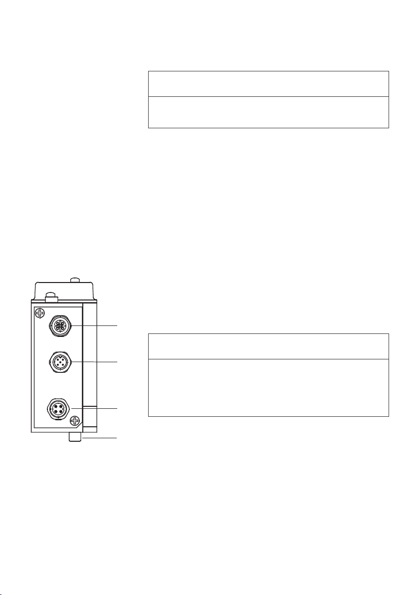
48 AVENTICS | DDL | R499050031–BAL–001–AH
Bus Coupler
A short circuit can only be recognized if the output is driven.
An open output can only be recognized if it is not driven.
Parameter
As a parameter transmission is not available for the bus coupler
for DeviceNet, the default parameter are used for all DDL
participants.
W The default parameters are:
– Reaction upon DDL failure: values at 0
– Diagnosis message coils: at driven outputs
3.2.4 Connectors
1 XPD: DDL OUT 3 X1S: Power supply
2 X7D: DeviceNet connection 4 X2O: Valve driver
NOTICE
(only R412006998)
Fig. 14: Connectors
1
.
NOTICE
2
3
4
The connectors must not be plugged or pulled under load.
The assembly or the plugging and pulling of the bus coupler
onto the valve unit is only allowed when the device is off
circuit!
Power Supply
The power supply is connected via a circular plug X1S. Only
4 pin M12 connecting bushes should be used, whereas pin 5 is
closed in order to avoid a mix up with other connections. The
diameter of the wires should be chosen as big as possible, but
at least 0.5 mm
Both power supplies must be secured with external 3 A T fuses.
The maximum allowed current in the O V line is limited to 4 A by
the connector.
2
.
Page 49

AVENTICS | DDL | R499050031–BAL–001–AH 49
Bus Coupler
1
4
2 3
Fig. 15: X1S power supply
1 Pin 1: 24 V sensor voltage / electronics
2 Pin 2: 24 V valve voltage
3 Pin 3: 0 V
4 Pin 4: Function earth
The electronics of the bus coupler and the electronics of all
I/O modules and initiators connected to the DDL (with modules
without ext. voltage supply) are supplied via X1S, pin 1.
Via X1S, pin 2 the voltage for the valves must be supplied, if no
module with external power supply is used. Because of the
separate supply of this power supply it is possible, in an
emergency stop situation, only to turn off the valves, whereas
the PLC, the serial interfaces and the initiators remain in
operation. Turning off the power supply for the serial interface
can lead to the state STOP of the PLC.
The 24 V supplies must be effected out of a common power
supply unit respectively with a common O V connection.
A power supply unit with a secure separation according to
EN 60742, classification VDE 0551 should be used.
1
2
5
3
4
Fig. 16: X7D DeviceNet
data plug
Data Line DeviceNet
The connection to the bus system is effected via the data plug
X7D. According to the DeviceNet Norm a T connector is
necessary to connect the bus coupler with the DeviceNet.
1 Pin 1 = shield 3 Pin 3 = 0 V
2 Pin 2 = 12 ... 24 V
external CAN
4 Pin 4 = CAN H
5 Pin 5 = CAN L
English
Page 50

50 AVENTICS | DDL | R499050031–BAL–001–AH
Bus Coupler
Data Line DDL
The output of the DDL is short circuit protected at all lines.
Nevertheless DDL participants can be damaged if 24 V are
applied to the signal lines DDL H and DDL L. For this reason we
recommend to use pre configured cables (see chapter 5 “DDL
Accessories“). The allocation of the DDL connections is
described in chapter 2.4 “DDL Data“.
The DDL end plug (see chapter 5 “DDL Accessories“) is
necessary to guarantee a definite termination of the line and the
protection degree IP 65, if the module is the last or the only
participant of a DDL line.
3.2.5 Technical Data
DeviceNet
Technical Data
Operating voltage valves 24 V DC +10 -0 %
Operating voltage electronics 24 V DC ±20 %
Fuse of valve voltage external 3 A T
Fuse of electronics external 3 A T
Attention: Maximum power in OV line 4 A
Voltage drop intern 0.8 V
Supply electronics 300 mA
Power supply for sensors max. 3 A per DDL branch
Power supply for valves max. 3 A per DDL branch
Number of output bytes
(only R412006998)
Ambient temperature range +5°C ... +50°C
Stock temperature -20°C ... +70°C
Protection class (with closed
connectors)
Installation position arbitrary
Further technical Data s. quotation drawing
* With a current I of max. 2 A per valve and sensor
1 / 2 / 3 / 4 Byte
+5°C ... +40°C (ATEX)
+5°C ... +50°C (ATEX)*
IP 65
IP 54 (ATEX)
Page 51

AVENTICS | DDL | R499050031–BAL–001–AH 51
Bus Coupler
3.2.6 Dimensions
45 107
POWER SUPPLY
VALVESENSOR
DDL
5V
MNS
RUN
0
1
9
2
8
3
7
4
6
5
112
0
1
9
2
8
3
7
4
6
5
8
9
7
A
B
6
C
5
D
4
E
3
F
2
0
1
21
Fig. 17: Dimensions of the bus coupler with drivers (R412006998)
113
5V
RUN
0
1
9
2
8
3
7
4
6
5
0
1
9
2
8
3
7
4
6
5
21
45
POWER SUPPLY
VALVESENSOR
DDL
MNS
120
140
30
Fig. 18: Dimensions of the bus coupler Stand alone (R412006999)
English
Page 52

52 AVENTICS | DDL | R499050031–BAL–001–AH
Bus Coupler
3.2.7 ATEX-Relevant Information
If the bus coupler DeviceNet R412006999 is used in zone 2,
attention has to be paid to the following ATEX-relevant
information.
See chapter 3.6.1 “Ex-Relevant Excerpt from the Operating
Instructions for S-Design Bus Couplers“.
3.3 Interbus S 337 500 045 0/337 500 046 0
The bus coupler for Interbus S is available in two different
designs. The bus coupler with drivers (337 500 046 0) can be
directly mounted onto a valve unit. In addition the control of this
unit the DDL is also available for other DDL participants.
The bus coupler Stand alone (337 500 045 0) is separately
mounted and provides only the DDL. Parts of the description
concerning the Slave module are not valid for the bus coupler
Stand alone.
3.3.1 Overview
Interbus S (IBS)
In the Interbus S process the data are serially pushed, in a
closed loop, through all participants until they reach the
dedicated address. There the output data (valve data) will be
verified regarding faults, will then be output and replaced by
input data (sensor state). These input data will be pushed into
the master in the next cycle whereas at the same time the new
output data are input into the loop. This principle permits to
send and receive during one cycle. Upon initialization all length
codes of the participants are read and recorded. The number of
reference data per participants and the number of the
participants has always to remain constant. The bus coupler is
integrated into the Interbus S system as remote bus participant.
A connection to a periphery bus is not possible.
Due to the word orientation of the in and output data there will
be an exchange of high and lowbyte with byte oriented PLC
Page 53

AVENTICS | DDL | R499050031–BAL–001–AH 53
Bus Coupler
types (e. g. Siemens S7). If, for example, the address 30 has
been allocated as data word, bits 0 ... 7 will appear in address
31.0 ... 31.7, bits 8 ... 15 in address 30.0 ... 30.7.
For information regarding the network build up and the
packing of the lines, please refer to the documentation of
the company Phoenix Contact or the Interbus Club.
Bus coupler Interbus S
1
POWER SUPPLY
SENSOR
2
3
4
5V
SENSOR
RESREG
RESET
4321
5
6
7
8
1 2
DDL
DLL
VALVE
RBDA
BA
8
7
6
5
4
3
2
1
12141214121412
VALVE
4321
9
A
B
C
D
E
F
0
6
7
1
8
5
Fig. 19: LEDs and switches with 337 500 046 0
1 DDL LEDs 5 Interbus termination S2
2 Interbus S LEDs 6 DDL mode S3
3 Master module 7 Slave module
4 Interbus S DDL Mode S1 8 DDL address S4
English
Page 54

54 AVENTICS | DDL | R499050031–BAL–001–AH
Bus Coupler
3.3.2 Master Module
The Master module is the interface between the Interbus S and
the DDL. It controls the DDL and monitors the supply voltages.
Interbus S Addresses/Last Participant
The Interbus S address of the bus coupler results from the
position in the Interbus S system and can only be changed
through a change in the sequence of the participants. On
insertion or removal of a participant the addresses move within
the ring.
If the bus coupler is the last participant in the Interbus S, the
module must be correspondingly configured with switch S2.
Table 24: Interbus termination
Switch Position 1 Position 2
S2 not last IBS participant (default) last IBS participant
Interbus S Baud Rates
The baud rate of the Interbus is 500 kBaud and cannot be
changed.
ON OPEN
21436587
S1
OPEN
ON
Fig. 20: DIP switch S1
Interbus S Parameter
The bus coupler behaves like a digital in/output unit and reports
back as a module type (identification) 03H.
The length code of the bus coupler has to be firmly set for
Interbus S, as the Interbus configuration depends on this.
Depending on the used data length of the DDL participant the
Interbus length code of the bus coupler can be optimized. The
length code is configured to the maximum unit’s stage of
expansion of 10 words (length code 0AH). This length code is
adjusted with switch S1.
The length code has to be calculated via the DDL configuration
through the user, before initial operation.
The length code has to be determined as follows:
The maximum length can be calculated with the output data
length plus 1 byte (diagnostic request without parameter
transmission) respectively 4 byte (diagnostic request with
Page 55

AVENTICS | DDL | R499050031–BAL–001–AH 55
Bus Coupler
parameter transmission) or the input data length plus 4 byte
diagnosis address and – data. Here the greater value has to be
used.
The in or output data range is the result of all data lengths of
employed DDL participants.
How the different data ranges are composed can be taken from
the corresponding chapters.
The data length in the DDL refers to bytes. The
configuration of bus coupler‘s length code is adjusted word
wise. Uneven byte sums have to be rounded up!
Example configuration for length code determination:
Parameters shall be transferred.
Table 25: Example for length code determination
DDL Device Order No. Output Data Input Data Diagnosis Data
bus coupler with
drivers (2 byte)
valve driver
(3 byte)
input module
(2 byte)
valve
(2 byte)
337 500 046 0 2 byte – 3 byte + 3 byte
= 7 byte
337 500 005 0 3 byte – 1 byte + 3 byte
= 4 byte
337 500 200 0 – 2 byte 1 byte
561 014 155 0 2 byte 2 byte 1 byte
7 byte 4 byte 13 byte
English
a) Output data:
7 byte output data + 4 byte parameter transmission and
diagnosis request = 11 byte (12 byte rounded up) = 6 words
length code
b) Input data:
4 byte input data + 4 byte diagnosis address and data = 8 byte
= 4 words length code
c) Length code:
6 words (a) > 4 words (b) = length code = 6 words
In table 26 the complete diagnosis rage is shown, which is
available via the diagnosis request.
Page 56

56 AVENTICS | DDL | R499050031–BAL–001–AH
Bus Coupler
If the length code has been determined, it can be adjusted with
switch S1 according to the following table:
Table 26: Length code of the bus coupler in the Interbus S
Bit 1 Bit 2 Bit 3 Bit 4
Open Open Open Open 1 Open Open Open On 8
On Open Open Open 1 On Open Open On 9
Open On Open Open 2 Open On Open On 10
On On Open Open 3 On On Open On 1
Open Open On Open 4 Open Open On On 2
On Open On Open 5 On Open On On 3
Open On On Open 6 Open On On On 4
On On On Open 7 On On On On 5
Length Code
(Words)
Bit 1 Bit 2 Bit 3 Bit 4
Parameter
The Interbus S does not offer a special possibility to transfer
parameter to the bus coupler. For this reason it is not possible
to parameterize the Master module. There is, however, an
option to configure the parameters of the DDL participants or
the Slave module via the Interbus. This can be effected via the
output data field of the bus coupler (see table 27).
The parameterization of the DDL participants can be activated
at the bus coupler. If the parameter transmission is not
activated, the DDL participants use their default parameter. The
parameter transmission is adjusted with switch S1 bit 7.
Table 27: Configuration of the parameter transmission
Length Code
(Words)
Switch S1 Open On
bit 7 no parameter transmission
(default)
parameter transmission
Parameter can only be changed after a voltage reset.
The switches bit 5 and 6 of switch S1 have no function.
Page 57

AVENTICS | DDL | R499050031–BAL–001–AH 57
Bus Coupler
Bus Coupler Parameter
The Master module does not provide parameters. With
Interbus S failure all outputs are set at 0.
DDL Participants Parameter
The parameter descriptions of the different DDL participants
can be taken from the corresponding chapters.
Parameter Transmission
In order to transmit parameter to the DDL system, the Master
module has to be configured correspondingly (see table 26).
Upon activated parameter transmission, all required
parameters and the check sum (sum of all parameter bytes) has
to be correctly transmitted first, (bytes 0 ... 13: parameter bytes
of the single DDL participants (1 ... 14), byte 14: check sum),
before the DDL system will be initialized. It is recommended to
transmit all 14 parameter bytes and the checksum always. For
not used parameter bytes 00h has to be used. If the calculated
check sum has the value 01, 55 must be send instead! If no
parameters have been sent, or if the checksum is not ok, this is
reported via the diagnosis to the control. By way of security
parameters shall be sent several times. Only the values sent
last will be valid. The sequence the parameters are transmitted
is not relevant.
The parameter bytes can be transmitted single or pair wise (see
output data field parameter byte X and X+1).
As soon as the DDL is initialized parameters cannot be changed
any longer. The parameter values and their meaning can be
taken from the documentation of the DDL participants.
The checksum results from the sum of the single parameter
bytes (without overflow).
The change of parameter data is only possible after a voltage
reset of the Master module.
English
Page 58

58 AVENTICS | DDL | R499050031–BAL–001–AH
Bus Coupler
Table 28: Example for parameter checksum
Byte Address 0 Node 1: 01h Node1: 01h Node1: 01h Node1: 00h
Byte Address 1 Node 2: F0h Node2: 00h Node2: 08h Node2: 00h
Byte Address 2 Node 3: 0Fh Node3: 00h Node3: 04h Node3: 00h
Byte Address 14 Checksum: 00h Checksum: 55h! (01) Checksum: 0Dh Checksum: 00h
DDL Address
At the Master module respectively. Stand alone bus coupler no
DDL Address has to be set.
For correct function of the DDL (Drive & Diagnostic Link)
following items must be fulfilled:
W same Baud rate at all DDL modules
W DDL Address within 1 ... 14, starting with 1, without gap, no
double used Address
W DDL Address 0: see chapter 2.2 “DDL Addressing“
DDL Mode
The DDL baud rate is adjusted with the bit 8 of DIP switch S1. All
participants must have the same baud rate.
Table 29: DDL baud rate
Bit Open On
8 DDL 125 kBaud DDL 250 kBaud (default)
Output and Input Data Fields of the Master Module
Because of the determined data length of each participant in the
Interbus S, only the in and output data are transmitted in each
cycle. The single diagnosis data have to be requested by the
control.
Page 59

Without parameter bytes
AVENTICS | DDL | R499050031–BAL–001–AH 59
Output Data Field
Table 30: Output data field without parameters
Byte Regarding
W0
DDL node 1 output data
Lo
W0
Hi
–
–
WY-1
Hi
WY
Lo
WY
Hi
–
–
–
–
–
–
DDL node n output data
Bus
coupler
7 6 5 4 3 2 1 0
–––
Bit
output data
–
–
output data
byte address requested
Bus Coupler
diagnosis byte X
(5 bit)
With parameter bytes
Table 31: Output data field with parameter
Byte Regarding
W0
DDL node 1 output data
Lo
W0
Hi
–
–
WY-1 LoBus
WY-1 HiBus
WY
Lo
WY
Hi
–
–
DDL node n output data
coupler
coupler
Bus
coupler
Bus
coupler
7 6 5 4 3 2 1 0
parameter byte X
parameter byte X + 1
––––
–––
Bit
–
–
byte address sent
parameter byte (4 bit)
byte address requested
diagnosis byte (5 bit)
English
Page 60

60 AVENTICS | DDL | R499050031–BAL–001–AH
Bus Coupler
Output data field:
W W0- Wy:
– Output data of connected DDL participants, as well as byte
addresses for Diagnosis and parameter. (The word length
(Wy) results from the configured data lengths at the
Master module (see Interbus S Parameter)
W WyHi:
– The byte address of requested diagnosis data (5 Bit)
If parameter data shall be transmitted (S1 switch 7 at ON) the
byte address is transmitted in the address WyLo and in word
Wy-1 the parameter data.
Input Data Field
Table 32: Input Data Field
Byte Regarding
W0
Lo
W0
Hi
W1
Lo
W1
Hi
W2
Lo
–
–
Wy
Hi
Bus
coupler
Bus
coupler
Bus
coupler
Bus
coupler
DDL node 1 input data
–
–
DDL node n input data
7 6 5 4 3 2 1 0
– – – byte address requested diagnosis byte X (5 Bit)
DDL
Heartbeat
length of the total input range in byte (7 bit)
= (W0Hi + input data + diagnosis data field (2 byte))
diagnosis byte X + 1
Bit
diagnosis byte X
–
–
Input data field:
W W0Lo-
– W0Hi are always sent, independent from the number of
connected DDL participants
Page 61

AVENTICS | DDL | R499050031–BAL–001–AH 61
Bus Coupler
W W0Lo:
– Start address of the requested diagnosis byte in the output
data field
W W0Hi:
– Bit 0 ... 6: Length of the complete input range in byte (min
4)
– Bit 7: DDL Heartbeat. Changes all 2 ... 3 sec.
W W1Lo:
– requested diagnosis byte
W W1Hi:
– requested diagnosis byte +1
W W2- Wy:
– Input data of the connected DDL devices. (length (Wy)
results from data length configured at the master (see
Interbus S Parameter)
Diagnosis
LED diagnosis On the top of the device LEDs indicate the state of the Interbus S
interface. The power supply is monitored in the Slave module.
Table 33: Overview of the Interbus LED indications
LED Function
ALLE off no power supply, not online
+5V flashing green supply for bus driver is missing
lighting green supply of processors within the tolerance
off No power supply, not online
BUS Res.Reg. green incoming interface switched on, system data transfer takes place
RBDA red incoming interface turned off;
Bus master caused RESET;
LED Res. Reg. green: module waits for initialization
RESET green supply of the decoupled interbus inputs within the tolerance
BA green reference data transfer takes place (BUS ACTIV)
English
Page 62

62 AVENTICS | DDL | R499050031–BAL–001–AH
Bus Coupler
Table 34: Overview of the DDL LEDs
LED Color of the LED meaning
SUPPLY
SENSOR
SUPPLY
VALVE
DDL red lighting no DDL communication (see page 62)
green lighting Voltage within the tolerance
green flashing Voltage below or beyond the tolerance
green off No voltage at connection sensor supply (X1S, Pin 1)
green lighting Voltage within the tolerance
green flashing Voltage below or beyond the tolerance
green off No voltage at connection sensor supply (X1S, Pin 1)
The limits of the power supply (electronics/valves) are 19.2 V/
21.6 V for low voltage and at 28.8 V/26.4 V for overvoltage. The
voltages are measured at plug DDL OUT.
The LED DDL indicates that no communication of reference data
takes place in the DDL. This can be due to:
W The adjusted baud rate of the DDL modules is not even
W Gaps in the addressing
W Same address has been assigned for 2 modules
W Address 0 and 1 ... 14 have been assigned at the same time
W Configuration has changed during operation
Voltage Monitoring The applied voltage supplies are indicated by two green LEDs:
The voltages at plug DDL are indicated. The thresholds of the
power supply (electronic/valves) are at 19.2 V/21.6 V for under
voltage and at 28.8 V/26.4 V for over voltage.
Short Circuit Monitoring The bus coupler has a short circuit monitoring for the DDL. Both
supply voltages are controlled independently from each other. If
the short circuit monitoring in the bus coupler is activated, the
corresponding LED will start to flash.
Software Diagnosis The complete diagnosis range is deposited in the DDL. This can
be requested via the in and output data fields. The diagnosis
area can be calculated from the sum of all single diagnosis
areas. Thereby it has to be taken into consideration, that also the
bus coupler (Master module) provides 3 bytes of diagnosis data.
The length of the single participants can be taken from the
corresponding descriptions.
Page 63

AVENTICS | DDL | R499050031–BAL–001–AH 63
After power up the configuration of the DDL will be determined.
Thereby the figure and the address of the connected DDL
participants, their data length and their type will be determined.
After approx. 5 sec this configuration will be redone and
compared to the first one. A difference between the determined
configurations will be reported as configuration error (byte 0,
bit 5). The configuration will also be verified, if the total output
data range is set at 0 (set value = 0), for more than 5 sec. The in
and output data of the participants will not be influenced hereby.
Diagnosis data have to be requested by the highest byte of
the output data field!
Table 35: Diagnosis bits
DDL
gaps
between
0 and
1
...
14
mixed
DDL
addr.
#5
exists
DDL
addr.
#13
exists
Bit
DDL
no units
at DDL
DDL
addr.
#4
exists
DDL
addr.
#12
exists
24 V
electronic
input
diagnosis
DDL
addr.
#3
exists
DDL
addr.
#11
exists
valve
voltage at
output
diagnosis
addr.
exists
addr.
exists
valve
supply
diagnosis
Regardin
g
Byte
bus
0
coupler
bus
1
coupler
bus
2
coupler
diagnosis
3
DDL
addr. 1
diagnosis
4
DDL addr. XXXX XXX XXX XXX XXX XXX XXX XXX
7 6 5 4 3 2 1 0
Check
sum,
param.
–
DDL
addr.
#8
exists
––
DDL
comm.
diagnosi
s
byte
uneven /
param.
incom-
plete
DDL
addr.
#7
exists
–– –––
DDL
Length of
output
data has
changed
since last
cofigu-
ration
DDL
addr.
#6
exists
DDL
addr.
#14
exists
addresses
or address
have been
Bus Coupler
24 V
DDL
DDL
#2
DDL
#10
24 V
24 V
electronic
voltage at
DDL
output
diagnosis
DDL
addr.
#1
exists
DDL
addr.
#9
exists
24 V
electronic
supply
diagnosis
English
5
diagnosis
DDL addr.
max.
XXX XXX XXX XXX XXX XXX XXX XXX
Page 64

64 AVENTICS | DDL | R499050031–BAL–001–AH
Bus Coupler
W XXX = Standard diagnosis bit or additional diagnosis with
valve drivers (e. g. Slave module)
W Byte 0:
– Bit 0: Electronic power supply of the subsequent DDL
modules below 19.2 V or beyond 28.8 V
– Bit 1: Valve power supply of the subsequent DDL modules
below 21.6 V or beyond 26.4 V
– Bit 2: Power supply of the Master module electronic below
19.2 V or beyond 28.8 V
– Bit 3: No external modules connected to DDL
– Bit 4: Gaps between addresses, address 0 and 1 ... 14 have
been mixed up or addresses have been assigned twice (it
cannot be assured that double addresses are recognized
safely)
– Bit 5: Data length of the outputs has changed since that
last configuration. The diagnosis disappears after a new
configuration (all set values will be set at 0 for more than
5 sec).
– Bit 6: The sum of the parameter data of the DDL participants
1
...
14 (parameter bytes 0
(parameter byte 14). Only if the parameter data have been
recognized correctly, the DDL System will be initialized. Upon
deactivated parameter transmission this bit is not active.
– Bit 7: no meaning
W Bytes 1 and 2: life bits of DDL participants
– Bits 1.0 ... 2.5 one bit set per existing device (14 devices
maximum). Bit position is in correspondence with the DDL
address. Bit is set to 0 after a communication diagnosis or
is set to 1 after return of the device with the diagnosis.
– With automatic addressing the following is valid:
Bit 0: Pressure control valve
Bit 1: Valve driver
Bit 2: Input module
Bit 3: Output module
Bit 4: Combi module
W Bit 2.6. and 2.7.: no meaning
W Bytes 3 ... 5: Diagnosis data of the connected DDL
participants
...
13) are uneven to the check sum
Page 65

AVENTICS | DDL | R499050031–BAL–001–AH 65
Bus Coupler
3.3.3 Slave Module
The Slave module behaves like a DDL participant for valve
control but it is situated within the housing of the bus coupler.
According to this a DDL address and a baud rate have to be
adjusted! The connection to the valve unit is effected via a 25 pin
D-Sub plug at the bottom side of the module.
DDL Address
The DDL address is adjusted with the switch S4. The regulation for
the adjustment can be found in chapter 2.2 “DDL Addressing“.
DDL Mode
The DDL baud rate is adjusted with switch S3. All participants
have to be adjusted to the same baud rate.
Table 36: DDL baud rate
Bit Open On
1 DDL 125 kBaud DDL 250 kBaud (default)
2 no function no function
OPEN ON
S3
2
1
0
F
OPEN
Fig. 21: DIP switch S3
Output Data Length
With switch S3 the number of outputs is adjusted. With this it is
possible to optimize the needed data range of the control for
43
21
5
4
3
6
7
8
9
A
B
E
C
D
ON
smaller valve units.
Table 37: Data length
Bit 3 Bit 4 Data length
Open Open 1 byte
On Open 1 byte
Open On 1 byte
On On 4 Byte (default)
The 4 byte mode offers a conformity with 16bit PLC systems.
But only the first 3 bytes are transferred to the outputs of the
D-Sub plug.
English
Page 66
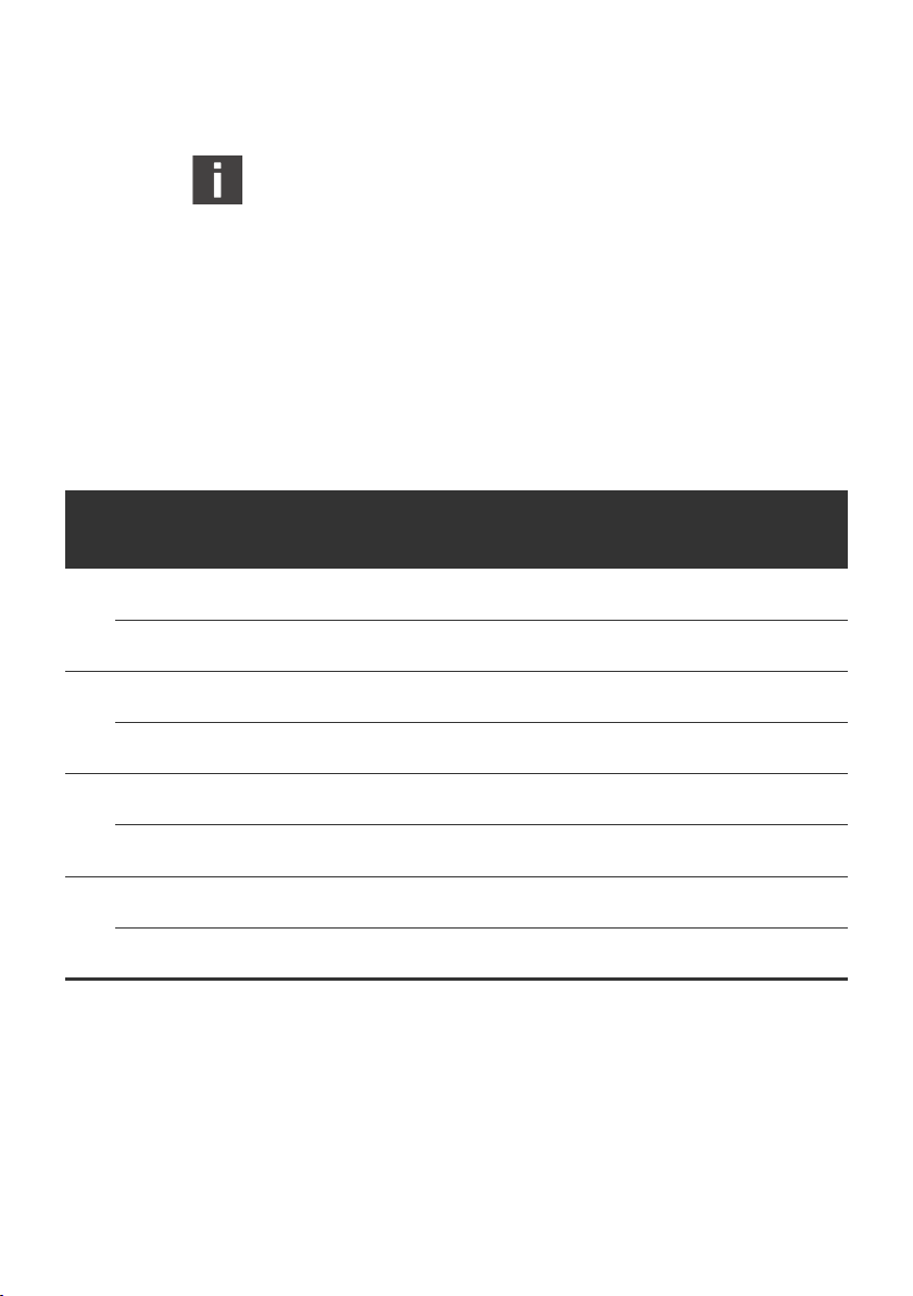
66 AVENTICS | DDL | R499050031–BAL–001–AH
Bus Coupler
The switches must not be changed during operation.
Changed switch positions will only become valid, after the
device has been turned off and restarted.
Output Data Range in the Control
The DDL address determines the position of the output data in
the data range of bus coupler and therefore the position in the
address range of the control. The valve driver occupies,
depending on the length set, 1 ... 4 byte in the output range of the
control. Whereby the 4th byte does not represent real outputs
and serves only for the 16 bit conformity.
Table 38: Output bits
Byte Regarding
valve unit
X
Pin 25 pol.
D-Sub
valve unit
X + 1
Pin 25 pol.
D-Sub
valve unit
X + 2
Pin 25 pol.
D-Sub
valve unit
X + 3
Pin 25 pol.
D-Sub
7 6 5 4 3 2 1 0
output7output6output5output4output3output2output1output
87654321
output15output14output13output12output11output10output9output
16 15 14 13 12 11 10 9
output23output22output21output20output19output18output17output
24 23 22 21 20 19 18 17
not
existent
Nc Nc Nc Nc Nc Nc Nc Nc
not
existent
not
existent
not
existent
Bit
existent
not
not
existent
not
existent
0
8
16
not
existent
At Pin 25 of 25 pol. D-Sub plug 0 V is connected.
If address 0 (automatic addressing) is set, the bus coupler with
driver behaves like a valve driver. Further information can be
taken from chapter 2.2 “DDL Addressing“.
The valve driver does not occupy any data in the input range,
only within the diagnosis range of the DDL.
Byte X is the start address in the output data range of the DDL
participant in the control.
Page 67

LED Diagnosis
AVENTICS | DDL | R499050031–BAL–001–AH 67
Bus Coupler
Diagnosis
Table 39: Overview of the DDL LED indication
Description Color of LED Meaning
SUPPLY
SENSOR
SUPPLY
VALVE
DDL red lighting no DDL communication (see below)
The limits of power supply (electronics/valves) are at 19.2 V/
21.6 V for low voltage and at 28.8/26.4 V for overvoltage. The
voltages are measured at plug DDL OUT. The LED DDL indicates
that no reference data communication takes place in the DDL
system. This can be due to:
W The adjusted baud rate of the DDL modules is not equal
W Gaps in the addressing
W Same address has been assigned for 2 modules
W Address 0 and 1 ... 14 have been assigned at the same time
W Configuration has changed during operation
green lighting voltage within the tolerance
green flashing voltage below or beyond the
tolerance
green off no voltage at connection sensor
supply (X1S, Pin 1)
green lighting voltage within the tolerance
green flashing voltage below or beyond the
tolerance
green off no voltage at connection sensor
supply (X1S, Pin 1)
English
Software Diagnosis The diagnosis data of the Slave module are in the diagnosis data
range according to the DDL address. If address 0 (automatic
addressing) is set, the bus coupler with driver behaves like a
valve driver. Further information can be taken from chapter 2.2
“DDL Addressing“.
The length of the diagnosis range is 1 byte + the adjusted output
data length. With bus coupler 337 500 046 0 the outputs 24 ... 31
do not really exist. For this reason there is no rational diagnosis.
With smaller valve units further outputs and their diagnosis can
not be used.
Page 68

68 AVENTICS | DDL | R499050031–BAL–001–AH
Bus Coupler
Table 40: Diagnosis bits
output
4
output
12
output
20
output
28
Bit
output
diagnosis
output
diagnosis
output
diagnosis
output
diagnosis
11
19
27
24 V
valve
supply
diagnosis
3
output
2
diagnosis
output
10
diagnosis
output
18
diagnosis
output
26
diagnosis
output
1
diagnosis
output
9
diagnosis
output
17
diagnosis
output
25
diagnosis
Byte
Z + 1
Z + 2
Z + 3
Z + 4
Z
7 6 5 4 3 2 1 0
DDL
comm.
diagnosis
output
7
diagnosis
output
15
diagnosis
output
23
diagnosis
output
31
diagnosis
–––––
output
6
diagnosis
output
14
diagnosis
output
22
diagnosis
output
30
diagnosis
output
5
diagnosis
output
13
diagnosis
output
21
diagnosis
output
29
diagnosis
diagnosis
diagnosis
diagnosis
diagnosis
Meaning of the bits W Byte Z Bit 0: Power supply of the electronics below 19.2 V or
beyond 28.8 V
W Byte Z Bit 1: Power supply of the valves below 21.6 V or
beyond 26.4 V
W Byte Z Bit 7: Communication to the DDL module interrupted
W Byte (Z + 1) – (Z + 4) Bit 0 ... 7: Output short circuit or open
(see description of the parameter).
W Byte Z is the start address of the diagnosis range of the DDL
participant in the control.
24 V
electronic
supply
diagnosis
output
0
diagnosis
output
8
diagnosis
output
16
diagnosis
output
24
diagnosis
NOTICE
A short circuit can only be detected if the output is driven.
An open output can only be detected if it is not driven.
Page 69

AVENTICS | DDL | R499050031–BAL–001–AH 69
Bus Coupler
Parameter
The Slave module provides the DDL master module for
Interbus S with these functions. For each DDL participant one
byte for parameter is available. The parameters are not
transferred cyclically. The parameter byte can be adjusted
individually for each participant. With the Interbus S bus coupler
the parameter of the DDL participants can be configured via the
output data field If the parameter transmission is deactivated,
the Slave module uses default parameter.
Table 41: Parameters for the Slave module
Bit Parameter Name Bit = 0 Bit = 1
7 reserved
6 reserved
5 reserved
4 reserved
3 reaction at DDL failure values at 0 (default) freeze values
2 reserved
1 diagnosis message of the coils with controlled outputs (default) changes are transferred
0 reserved
Bit 1 = 0 Output based diagnosis messages are only sent, if the output is
controlled. Upon starting the system it is not checked, which
coils do exist. If an output is controlled, where no coil exists, a
diagnosis message is generated.
Bit 1 = 1 With Interbus S diagnosis data can be recalled cyclically.
Thereby missing coils can be determined upon the start of the
system. During the cyclic operation diagnosis messages are
only transmitted, if there have been changes. Open circuit is
immediately reported, the valve needs not to be controlled.
Bit 3 = 0 Upon failure of the DDL, the output data are set at 0 in the Slave
module.
Bit 3 = 1 Upon failure of the DDL, the output data are stored in the Slave
module and the coils will still be controlled (freezing values).
English
Page 70

70 AVENTICS | DDL | R499050031–BAL–001–AH
Bus Coupler
Changed parameters only become valid, if the device has
been switched off and has been restarted.
3.3.4 Connectors
1 X7J2: Interbus S Input
2 X7J1: Interbus S Output
3 XPD: DDL OUT
1
2
4 X1S: Power supply
5 X2O: Valve driver (only 337 500 046 0)
.
Fig. 22: Connectors
1
4
2 3
Fig. 23: X1S Power Supply
3
4
5
The connectors must not be plugged or pulled under load.
The assembly or the plugging and pulling of the bus coupler
onto the valve unit is only allowed when the device is off
circuit!
NOTICE
Power Supply
The power supply is effected via the circular plug X1S. Only
4 pin M12 connecting bushes should be used, where pin 5 is
closed; in order to avoid a mix up with other connections. The
diameter of the wires should be chosen as big as possible, but
at least 0.5 mm
Both power supplies must be secured with external 3 A T fuses.
The maximum allowed voltage in the O V line is limited to 4 A by
the connector
1 Pin 1: 24 V sensor voltage / electronics
2 Pin 2: 24 V valve voltage
3 Pin 3: 0 V
4 Pin 4: Function earth
The electronics of the bus coupler and the electronics of all
I/O modules and initiators connected to the DDL (with modules
without external power supply) are supplied via X1S, pin 1.
2
.
Page 71

4
X7J1: OUT
(female)
2
3
X7J2: IN
(male)
1
5
2 3
Fig. 24: Interbus S data plug
1
4
AVENTICS | DDL | R499050031–BAL–001–AH 71
If modules without an external power supply are used, the
switching voltage for connected valves must be supplied via
X1S, pin 2. Because of the separate supply of this power supply
it is possible, in an emergency stop situation, only to turn off the
valves, whereas the PLC, the serial interfaces and the initiators
remain in operation. Turning off the power supply for the serial
interface can lead to the state STOP of the PLC.
The 24 V supplies must be effected out of a common power
supply unit respectively with a common O V connection.
A power supply unit with a secure separation according to
EN 60742, classification VDE 0551 should be used.
Data Line Interbus S
The connection to the bus system is effected with data plug M12,
5 pin. B coded female at Interbus S IN (X7J2) or male at Interbus
S OUT (X7J1).
1 Pin 1: DO
2 Pin 2: /DO
3 Pin 3: DI
4 Pin 4: /DI
5
5 Pin 5: GND
Data Line DDL
The output of the DDL is short circuit protected for all lines.
Nevertheless DDL participants can be damaged if 24 V is
applied to signal lines DDL H and DDL L. For this reason we
recommend to use pre configured cables (see chapter 5 “DDL
Accessories“). The allocation of the DDL connectors is described
in chapter 2.4 “DDL Data“.
The DDL end plug (see chapter 5 “DDL Accessories“) is
necessary to guarantee a definite termination of the line and the
protection degree IP 65, if the module is the last or the only
participant of a DDL line.
Bus Coupler
English
Page 72

72 AVENTICS | DDL | R499050031–BAL–001–AH
Bus Coupler
3.3.5 Technical Data
Interbus S
Technical Data
Operating voltage valves 24 V DC +10 -0 %
Operating voltage electronics 24 V DC ±20 %
Fuse of the valve voltage external 3 A T
Fuse of electronics external 3 A T
Attention: Maximum current
in the 0 V line
Voltage drop, internal 0.8 V
Required power electronics 90 mA
Power supply for sensors max. 3 A per DDL branch
Power supply for valves max. 3 A per DDL branch
Number of output bytes
(for 337 500 046 0)
Ambient temperature range +5°C ... +50°C
Stock temperature -20°C ... +70°C
Protection class (with closed
connectors)
Installation position arbitrary
Further technical Data s. quotation drawing
* With a current I of max. 2 A per valve and sensor
max. 4 A
1 / 2 / 3 / 4 byte
+5°C ... +40°C (ATEX)
+5°C ... +50°C (ATEX)*
IP 65
IP 54 (ATEX)
Page 73

AVENTICS | DDL | R499050031–BAL–001–AH 73
3.3.6 Dimensions
Bus Coupler
107
5V
SENSOR
RESREG
RESET
4321
5
6
7
8
1 2
45
SENSOR
DDL
VALVE
RBDA
BA
POWER SUPPLY
VALVE
DDL
4321
9
8
A
7
B
6
C
5
D
4
E
3
F
2
0
1
104
Fig. 25: Dimensions of the bus coupler with drivers (337 500 046 0)
113
DDL
5V
VALVE
SENSOR
RESREG
RBDA
BA
RESET
English
4321
5
6
7
8
1 2
120
140
30
45
Fig. 26: Dimensions of the bus coupler Stand alone (337 500 045 0)
Page 74

74 AVENTICS | DDL | R499050031–BAL–001–AH
Bus Coupler
3.3.7 ATEX-Relevant Information
If the bus coupler Interbus S 337 500 045 0 is used in zone 2,
attention has to be paid to the following ATEX-relevant
information.
See chapter 3.6.1 “Ex-Relevant Excerpt from the Operating
Instructions for S-Design Bus Couplers“.
3.4 ControlNet 337 500 056 0
The bus coupler for ControlNet is available in two different
designs. The bus coupler with drivers (337 500 056 0) can be
mounted directly onto a valve unit. In addition to the control of
this unit, the DDL is also available for further DDL participants.
The bus coupler Stand alone (order number on request) is
separately mounted and provides only the DDL. Part of the
description concerning the Slave module are not valid for the
bus coupler stand alone except for the monitoring of the voltage.
3.4.1 Overview
ControlNet
The ControlNet which is used for communication with the
control, is a fast working bus system to interchange time critical
user dates. It offers not only real time data transmission but
also intelligence service for direct data interchange between
2 participants. As a transmission medium a 75 Ω coaxial cable,
terminated at both sides is used.
The device has to be driven at channel A and does not support
redundant cabling.
Concerning the information for the assembly of the network
and also for the preparation of the lines, please refer to the
documentation of the company Rockwell Automation/AllenBradley.
Page 75
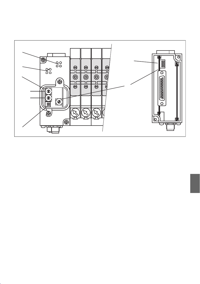
AVENTICS | DDL | R499050031–BAL–001–AH 75
Bus Coupler
Bus coupler ControlNet
1
POWER SUPPLY
A-RUN
DDL
STATUS
A-STOP
2
12141214121412
VALVESENSOR
7
4321
3
0
1
9
2
8
3
7
4
5
4
6
5
0
1
9
2
8
3
7
4
6
5
9
8
A
7
B
6
C
5
D
4
E
3
F
2
1
0
21
6
Fig. 27: LED and switch of 337 500 056 0
1 DDL LEDs 5 CN address S2
2 ControlNet LEDs 6 DDL Mode S3
3 Master module 7 DDL Mode S4
4 CN address S1 8 Slave module DDL address S5
3.4.2 Master Module
The Master module is the interface between the ControlNet and
the DDL. It controls the DDL and monitors the supply voltages.
ControlNet Address
A definite address is allocated to each participant in the
network. Via two rotary switches addresses from 0 ... 99 can be
set. With switch S1 the ten digit and with S2 the one digit is
adjusted. Address 0 and 1 are reserved for controls or for
temporary diagnosis devices and shall not be used. The devices
are already adjusted to address 2 in the factory.
8
1
English
Page 76

76 AVENTICS | DDL | R499050031–BAL–001–AH
Bus Coupler
ControlNet Baud Rate
The baud rate of the ControlNet is 5 MBaud and cannot be
changed.
ControlNet Parameter
The length of the output data range (valves, nominal value, ...) is
fixed to 16 byte (10 hex) maximum. The length of the input data
range (sensors, actual values, ...) is also limited to 16 byte
maximum. Due to the diagnosis data of the bus coupler and the
DDL participants the total input data range is enlarged up to
48 byte (30 hex). The diagnostic data is transmitted cyclic within
the input data range to in the PLC.
Table 42: ControlNet parameter
Assembly Instance max Size
Input 100 24 (16 bit)
Output 150 8 (16 bit)
Configuration 4 0 (8 bit)
An electronic data sheet (EDS) is available on the internet page
of the company HMS (http://www.hms-networks.com)
Type: EDS Configuration File
Name: AnyBus-S ControlNet
Parameter
Some field bus systems offer the possibility to transfer
parameters to the bus coupler and the DDL participants. At
present the bus coupler for ControlNet does not offer this.
Bus Coupler parameter The bus coupler does not provide parameter for modification.
Upon a failure of the ControlNet the bus coupler behave in that
way, that all output data are set at 0. Diagnostic data were
transmitted cyclic within the input data.
Page 77

AVENTICS | DDL | R499050031–BAL–001–AH 77
Bus Coupler
DDL participant
0
1
9
2
8
3
7
4
6
5
0
1
9
2
8
3
7
4
6
5
21
ON OPEN
parameter
S3
As with the bus coupler there is no parameter transfer for the
ControlNet available, the default parameters are used with all
DDL participants. They are mentioned in the corresponding
device descriptions.
DDL Address
At the Master module respectively stand alone bus coupler no
DDL Address has to be set.
For correct function of the DDL (Drive & Diagnostic Link)
following items must be fulfilled:
W same Baud rate at all DDL modules
W DDL Address within 1 ... 14, starting with 1, without gap, no
double used Address
W DDL Address 0: see chapter 2.2 “DDL Addressing“
DDL Mode
T
The baud rate of DDL is defined by the 2 pole DIP switch S3 next
to the ControNet address switches on the front side. All
participants have to be adjusted to the same transfer rate.
Table 43: DDL baud rate
Bit Open On
1 DDL 125 kBaud DDL 250 kBaud (default)
2 no function no function
OPEN
ON
Fig. 28: DIP switch S3:
DDL mode
LED diagnosis On the top side of the device the LEDs indicate the state of the
English
Diagnosis
ControlNet interface. The power supply is observed by the Slave
module. This applies also to the bus coupler Stand alone.
Page 78

78 AVENTICS | DDL | R499050031–BAL–001–AH
Bus Coupler
Table 44: Overview of CN LED indication
LED Color of LED Meaning
A-STOP red interference with cable connection
A-RUN green module connected with bus
Status left green scanner has recognized the device and
Status right green PLC in the RUN Mode and outputs are set
After the appliance of the power supply, the red LED lights for
approx. 1 second until other participants are recognized.
Depending on the state of initialization of the ControlNet
interface the A-RUN LED flashes according to the specification
or lights continuously. A missing terminating resistor or an
interfered connection can also provoke that the A-RUN (green)
and the A-STOP (red) LED flash reciprocally.
The left STATUS LED indicates that the control has recognized
the unit, has build up a connection and the incoming data are
already being read. If the PLC is switched into the RUN Mode, the
second STATUS LED lights and the outputs will be driven.
exchanges data
Voltage Monitoring The description of the voltage monitoring can be found in
chapter slave module.
Short Circuit Monitoring The bus coupler has a short circuit monitoring for the DDL. Both
power supplies are observed individually from each other. If a
short circuit monitoring is activated, the corresponding green
LED (see Voltage Monitoring) will be flashing.
Software – Diagnosis After activating the power the configuration of the DDL is
determined. Thereby the figure and the address of the
connected DDL participant, its data length and the type is
ascertained. After approx. 5 sec this configuration is redone and
compared to the first one. A difference of the determined
configurations is reported as a configuration error (byte 0, bit 5).
In addition the configuration is also examined. when the total
output data range is set at 0 for more than 5 sec (set value = 0).
Page 79

Table 45: Diagnosis bits
Byte
0– –
1
2
3– –
7 6 5 4 3 2 1 0
DDL
heartbeat
DDL addr.
exists
#8
DDL addr.
#7
exists
AVENTICS | DDL | R499050031–BAL–001–AH 79
Bus Coupler
The in and output data of the participants will not be influenced
thereby.
The software diagnosis of the Master module can be found in
the first 4 bytes of the adjusted input data area of the control,
before the input data. The whole software diagnosis of the other
DDL participants is behind the input data area of all DDL
participants. The length of the diagnosis range of further DDL
participants is 1 byte + the adjusted output data length with
valve drivers. With other participants the diagnosis length can
be taken from the corresponding descriptions.
Bit
DDL length
of the
output
data has
changed
since the
last
configu-
ration
DDL addr.
#6
exists
DDL addr.
#14
exists
DDL
gaps
between
addresses
or
address 0
and
1 ... 14
have been
mixed up.
length of the total input range (7 Bit)
DDL addr.
#5
exists
DDL addr.
#13
exists
DDL
no units
connected
to the DDL
DDL addr.
#4
exists
DDL addr.
#12
exists
24 V
electronic
supply
diagnosis
DDL addr.
#3
exists
DDL addr.
#11
exists
24 V
valve
supply at
DDL OUT
diagnosis
DDL addr.
#2
exists
DDL addr.
#10
exists
24 V
electronic
supply at
DDL OUT
diagnosis
DDL addr.
exists
DDL addr.
exists
#1
#9
English
Meaning of the
diagnosis bits
W Byte 0:
– Bit 0: Electronic power supply of the succeeding DDL
modules below 19.2 V or beyond 28.8 V
– Bit 1: Valve power supply of the succeeding DDL modules
below 21.6 V or beyond 26.4 V
– Bit 2: Power supply of the Master module electronic below
19.2 V or beyond 28.8 V
– Bit 3: No external modules connected to the DDL
Page 80

80 AVENTICS | DDL | R499050031–BAL–001–AH
Bus Coupler
– Bit 4: Gaps between addresses, address 0 and 1 ... 14 have
been mixed up or addresses have been assigned twice
– Bit 5: Since the last configuration the number of DDL
participants or the data length of the participants has
changed. This diagnosis appears also after a reset of the
power supply
W Byte 1:
– Bit 0 ... 6: Total length of the input data, including the
diagnosis data plus 4 byte of master diagnosis data
– Bit 7: DDL Heartbeat, is reversed all 2 ... 3 seconds
W Byte 2 + 3:
– Bit 0 ... 7: For each existing address the corresponding bit
is set.
– With automatic addressing the following is valid:
W Byte 2:
– Bit 0: Pressure control valve
– Bit 1: Valve driver
– Bit 2: Input module
– Bit 3: Output module
– Bit 4: Combi module
3.4.3 Slave Module
The Slave module behaves like a DDL participant for valve
control but it is situated within the housing of the bus coupler.
According to this a DDL address has to be adjusted! The
connection to the valve unit is effected via a 25 pin D-Sub plug
at the bottom side of the module.
DDL Address
The DDL address is adjusted with switch S5.
The adjustment regulations for the addressing are described in
chapter 2.2 “DDL Addressing“.
Page 81
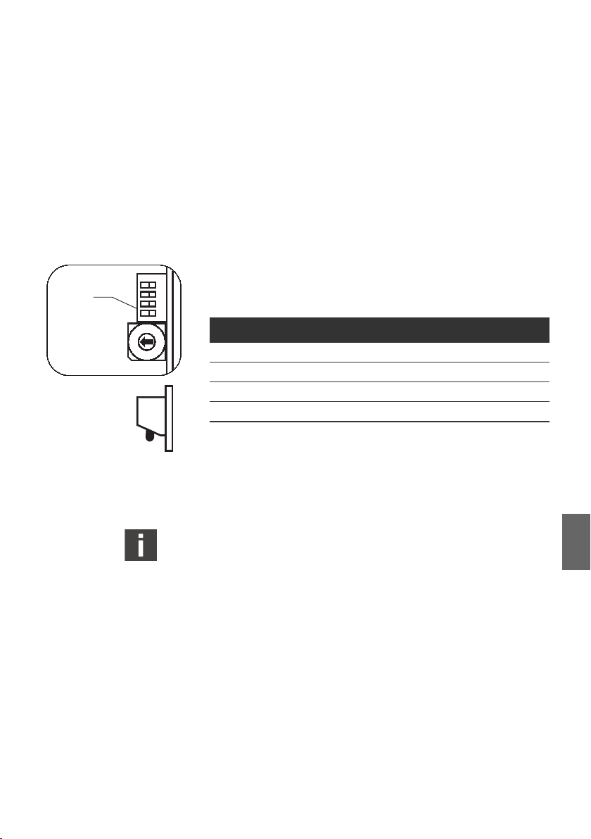
OPEN ON
S4
2
1
0
F
OPEN
Fig. 29: DIP switch S4
AVENTICS | DDL | R499050031–BAL–001–AH 81
Bus Coupler
DDL Mode
The DDL baud rate is adjusted with switch S4.
The configuration of the baud rate of the Master module is
combined with the baud rate configuration for the Slave module.
A description can be found in the chapter concerning the Master
module.
Output Data Length
With switch S4 the number of outputs is adjusted. This provides
the possibility to optimize the required data range in the control
43
21
5
4
3
6
7
8
9
A
B
E
C
D
ON
of smaller valve units.
Table 46: Data length
Bit 3 Bit 4 Data length
Open Open 1 Byte
On Open 2 Byte
Open On 3 Byte
On On 4 Byte (default)
The 4 byte mode offer a conformity with 16 Bit PLC systems.
Only the first 3 bytes are transferred to the outputs of the D-Sub
plug.
The switches must not be changed during operation.
Changed switch positions will only become valid, after the
device has been turned off and restarted.
Output Data Range in the Control
The DDL address determines the position of the output data in
the data range of the bus coupler and therefore the position of
the address range of the control.
The valve driver occupies, depending on the adjusted length,
1 ... 4 bytes of the output range. Whereby the 4th byte does not
represent real outputs and serves only for the 16 bit conformity.
English
Page 82

82 AVENTICS | DDL | R499050031–BAL–001–AH
Bus Coupler
Table 47: Output bits
Byte Regarding
valve unit
X
Pin 25 pol.
D-Sub
valve unit
X + 1
Pin 25 pol.
D-Sub
valve unit
X + 2
Pin 25 pol.
D-Sub
valve unit
X + 3
Pin 25 pol.
D-Sub
7 6 5 4 3 2 1 0
output7output6output5output4output3output2output1output
87654321
output15output14output13output12output11output10output9output
16 15 14 13 12 11 10 9
output23output22output21output20output19output18output17output
24 23 22 21 20 19 18 17
not
existent
Nc Nc Nc Nc Nc Nc Nc Nc
not
existent
not
existent
not
existent
Bit
existent
not
not
existent
not
existent
0
8
16
not
existent
0 V is connected to pin 25 of the 25 pole D-Sub plug.
If address 0 (automatic addressing) is set, the bus coupler with
driver behaves like a valve driver. Further information can be
taken from chapter 2.2 “DDL Addressing“.
The valve driver does not occupy any data in the input range,
only within the diagnosis range of the DDL.
Byte X is the start address of the output data range of the DDL
participant in the control.
Page 83

LED diagnosis
AVENTICS | DDL | R499050031–BAL–001–AH 83
Bus Coupler
Diagnosis
Table 48: Overview of the DDL LED indication
Description Color of LED Meaning
SUPPLY
SENSOR
SUPPLY
VALVE
DDL red lighting no DDL communication (see below)
The limits of power supply (electronics/valves) are at 19.2 V/
21.6 V for under voltage and at 28.8/26.4 V for overvoltage. The
voltages are measured at plug DDL OUT. The LED DDL indicates
that no reference data communication takes place in the DDL
system. This can be due to:
W The adjusted baud rate of the DDL modules is not equal
W Gaps in the addressing
W Same address has been assigned for 2 modules
W Address 0 and 1 ... 14 have been assigned at the same time
W Configuration has changed during operation
green lighting voltage within the tolerance
green flashing voltage below or beyond the
tolerance
green off no voltage at connection sensor
supply (X1S, Pin 1)
green lighting voltage within the tolerance
green flashing voltage below or beyond the
tolerance
green off no voltage at connection sensor
supply (X1S, Pin 1)
English
Voltage monitoring The applied voltage supplies are indicated by two green LEDs:
Voltages at the plug DDL are shown. The threshold of the power
supply (electronic/valves) are at 19.2 V/21.6 V for under voltage
and at 28.8 V/26.4 V for overvoltage.
Software diagnosis The software diagnosis of the Slave module is 1 byte standard
diagnosis + configured data length long.
With bus coupler 337 500 056 0 the outputs from 24 ... 31 are
not really existent. For this reason there is no rational diagnosis.
With smaller valve units further outputs and their diagnosis can
not be used.
Page 84

84 AVENTICS | DDL | R499050031–BAL–001–AH
Bus Coupler
The address range of the diagnosis derives from the DDL
address. If address 0 (automatic addressing) is set, the bus
coupler with driver behaves like a valve driver. Further
information can be taken from chapter 2.2 “DDL Addressing“.
Table 49: Diagnosis bits
Byte
Z + 1
Z + 2
Z + 3
Z + 4
Z
7 6 5 4 3 2 1 0
DDL
comm.
diagnosis
output
7
diagnosis
output
15
diagnosis
output
23
diagnosis
output
31
diagnosis
–––––
output
6
diagnosis
output
14
diagnosis
output
22
diagnosis
output
30
diagnosis
output
5
diagnosis
output
13
diagnosis
output
21
diagnosis
output
29
diagnosis
diagnosis
diagnosis
diagnosis
diagnosis
Bit
output
4
output
12
output
20
output
28
output
3
diagnosis
output
11
diagnosis
output
19
diagnosis
output
27
diagnosis
output
2
diagnosis
output
10
diagnosis
output
18
diagnosis
output
26
diagnosis
24 V
valve
supply
diagnosis
output
1
diagnosis
output
9
diagnosis
output
17
diagnosis
output
25
diagnosis
24 V
electronic
supply
diagnosis
output
0
diagnosis
output
8
diagnosis
output
16
diagnosis
output
24
diagnosis
Meaning of the bits: W Byte Z Bit 0: Power supply of the electronics below 19.2 V or
beyond 28.8 V
W Byte Z Bit 1: Power supply of the valves below 21.6 V or
beyond 26.4 V
W Byte Z Bit 7: Communication to the DDL module interrupted
W Byte (Z + 1) – (Z + 4) Bit 0 ... 7: Output short circuit or open.
W Byte Z is the start address of the diagnosis range of the DDL
participant in the control.
NOTICE
A short circuit can only be recognized if the output is
controlled. An open output can only be recognized, if it is not
controlled.
Page 85

AVENTICS | DDL | R499050031–BAL–001–AH 85
Parameter
As there is no parameter transmission with the bus coupler for
ControlNet, default parameter are used for all participants.
W The default parameters are:
– Reaction upon DDL failure: values at 0
– Diagnosis message coils: at driven outputs
3.4.4 Connections
1 XPD: DDL OUT 3 X1S: Power supply
2 X7D: ControlNet
connection
1
.
4 X2O: Valve driver
(only 337 500 056 0)
NOTICE
2
The connectors must not be plugged or pulled under load.
The assembly or the plugging and pulling of the bus coupler
onto the valve unit is only allowed when the device is off
circuit!
3
Bus Coupler
Fig. 30: Connectors
1
4
2 3
Fig. 31: X1S power supply
4
Power Supply
The power supply is connected via a circular plug X1S. Only
4-pin M12 connecting bushes should be used, whereas pin 5 is
closed in order to avoid a mix up with other connections. The
diameter of the wires should be chosen as big as possible, but
at least 0.5 mm
Both power supplies must be secured with external 3 A T fuses.
The maximum allowed voltage in the 0 V line is limited to 4 A by
the connector.
1 Pin 1: 24 V sensor voltage / electronics
2 Pin 2: 24 V valve voltage
3 Pin 3: 0 V
4 Pin 4: Function earth
2
.
English
Page 86

86 AVENTICS | DDL | R499050031–BAL–001–AH
Bus Coupler
The electronics of the bus coupler and the electronics of all I/O
modules and initiators connected to the DDL (with modules
without ext. voltage supply) are supplied via X1S, pin 1.
Via X1S, pin 2 the voltage for the valves must be supplied, if no
module with external power supply is used. Because of the
separate supply of this power supply it is possible, in an
emergency stop situation, only to turn off the valves, whereas
the PLC, the serial interfaces and the initiators remain in
operation. Turning off the power supply for the serial interface
can lead to the state STOP of the PLC.
The 24 V supplies must be effected via a common power
supply unit or with a common O V connector.
A power supply unit with a safety separation according to
EN 60742, classification VDE 0551.
Data Line ControlNet
The connection to the bus system is effected via the data plug
X7N. This is a BNC plug customary in the trade. For further
information we refer you to the documentation of the company
Rockwell Automation/Allen-Bradley.
Data Line DDL
The output of the DDL is short circuit protected at all lines.
Nevertheless DDL participants can be damaged if 24 V are
applied to the signal lines DDL H and DDL L. For this reason we
recommend to use pre configured cables (see chapter 5 “DDL
Accessories“). The allocation of the DDL connections is
described in chapter 2.4 “DDL Data“. The DDL end plug (see
chapter 5 “DDL Accessories“) is necessary to guarantee a
definite termination of the line and the protection degree IP 65,
if the module is the last or the only participant of a DDL line.
Page 87

AVENTICS | DDL | R499050031–BAL–001–AH 87
Bus Coupler
3.4.5 Technical Data
ControlNet
Technical Data
Operating voltage valves 24 V DC +10 -0 %
Operating voltage electronics 24 V DC ±20 %
Fuse of the valve voltage 3 A T
Fuse of electronics 3 A T
Attention: Maximum current in 0 V line 4 A
Voltage drop, internal 0.8 V
Required power 300 mA
Power supply for sensors max. 3 A per DDL branch
Power supply for valves max. 3 A per DDL branch
Number of output bytes
(for 337 500 056 0)
Ambient temperature range +5°C ... +50°C
Stock temperature -20°C ... +70°C
Protection class (with closed
connectors)
Installation position arbitrary
Further technical Data s. quotation drawing
1 / 2 / 3 / 4 byte
IP 65
English
Page 88

88 AVENTICS | DDL | R499050031–BAL–001–AH
Bus Coupler
3.4.6 Dimensions
45 107
POWER SUPPLY
VALVESENSOR
DDL
STATUS
A-RUN
A-STOP
0
1
9
2
8
3
7
4
6
5
112
0
1
9
2
8
3
7
4
6
5
9
8
A
7
B
6
C
5
D
4
E
3
F
2
1
0
21
Fig. 32: Dimensions of the bus coupler with drivers (337 500 056 0)
113
A-RUN
STATUS
0
1
9
8
7
6
5
0
1
9
8
7
6
5
21
2
3
4
2
3
4
45
DDL
A-STOP
POWER SUPPLY
VALVESENSOR
120
140
30
Fig. 33: Dimensions of the bus coupler stand alone (order number on
request)
Page 89

AVENTICS | DDL | R499050031–BAL–001–AH 89
Bus Coupler
3.5 CANopen R412008000/R412008002
The bus coupler for CANopen is available in two different
designs. The bus coupler with drivers (R412008002) can be
directly mounted onto a valve unit. In addition to the control of
this unit the DDL is also available for other DDL participants.
The bus coupler Stand alone (R412008000) is separately
mounted and provides only the DDL.
Parts of the description concerning the Slave module are not
valid for the bus coupler Stand alone.
3.5.1 Overview
CANopen
The CAN profile CANopen was standardized by manufacturers
and the user association CAN in Automation (CiA) under the
number CiA DS 301.
Realtime data are transmitted with so called process and data
objects (PDO). Parameter data, diagnosis data and program
data are transmitted with Service data objects (SDO). Both
objects are transmitted with different identifiers, which are
based on the adjusted module ID.
A PDO consists only process data and no program overhead. A
SDO otherwise consists in addition to the process data also the
information which object has to be used. In addition to the
regular objects as START, STOP or RESET some further optional
objects are defined. For the PLC configuration software, the EDS
file may be helpful.
The electronic data sheet (EDS) can be downloaded from the
Internet at www.aventics.com/mediadirectory:
DDL_co.eds
Type: EDS Configuration File
English
For information concerning the installation of the network
and regarding the preparation of the line and used objects
please refer to the documentation of CiA Draft
Standard 301 from CAN in Automation e. V.
Page 90

90 AVENTICS | DDL | R499050031–BAL–001–AH
Bus Coupler
Bus coupler CANopen
1
POWER SUPPLY
DDL
Valve
2
3
Sensor
OP
STOP
12141214121412
VALVESENSOR
4321
7
0
1
9
2
8
7
4
5
6
0
9
8
7
6
21
4321
3
4
5
1
2
3
4
5
9
8
A
7
B
6
C
5
D
4
E
3
F
2
1
0
6
Fig. 34: LEDs and switches of R412008002
1 DDL LEDs 6 CANopen baud rate S3
2 CANopen LEDs 7 Slave module DDL mode S6
3 Master module 8 DDL address S5 (R412008002)
4 CANopen address S1 9 CANopen baud rate
5 CANopen address S2
3.5.2 Master Module
The Master module is the interface between the CANopen and
the DDL. It controls the DDL and monitors the supply voltages.
CANopen Address
A definite address is allocated to each participant in the
network. Via two rotary switches addresses from 0 ... 99 can be
set. With switch S1 the ten digit and with S2 the one digit is
adjusted. The address 0 reserved for CANopen diagnosis
functions and may not be used. In the factory the devices are
adjusted to address 2.
8
1
9
DDL mode S4
Page 91

0
1
9
2
8
3
7
4
6
5
0
1
9
2
8
3
7
4
6
5
21
ON OPEN
OPEN
ON
Fig. 35: DIP switch S3:
DDL mode
S3
AVENTICS | DDL | R499050031–BAL–001–AH 91
Bus Coupler
CANopen Baud Rates
The baud rate of the CANopen system is adjusted with the 2 bit
DIP switch S3 and with bit 2 of the 4 bit DIP switch S4 on the
back side of the master module. For access to switch S4 at the
Bus coupler Stand alone R412008000 the bottom plate has to be
removed.
Table 50: Adjustment of the CANopen Baud rates
Bit 1 DIP S3 Bit 2 DIP S3 Bit 2 DIP S4 Baud rate
Open Open Open (default) 1000 kBaud
On Open Open (default) 800 kBaud
Open On Open (default) 500 kBaud
On (default) On (default) Open (default) 250 kBaud
Open Open On 125 kBaud
On Open On 100 kBaud
Open On On 50 kBaud
On On On 20 kBaud
CANopen Data
The length of the output data range (valves, nominal value, ...) is
fixed to 16 byte (10 hex) maximum. The length of the input data
range (sensors, actual values, ...) is also adjusted to 16 byte
maximum. With each TXD-PDO 8 data bytes are transmitted
respectively requested with each RXD-PDO. In the
communication area of the object dictionary the PDOs can be
found under the index 1401 respectively 1400 (Transmit) and
1801 respectively 1800 (Receive).
Additionally it is possible to force the output data in the
parameter area of the object dictionary with the index 6200 and
6300 within the subindexes 1 ... 8 each. The input data can be
requested with the index 6000 and 6100 also within the
subindexes 1 ... 8 each.
English
Parameter
The CANopen bus coupler provides the transmission of special
communication profile objects as e.g. NodeGuarding.
Page 92

92 AVENTICS | DDL | R499050031–BAL–001–AH
Bus Coupler
Bus Coupler Parameters
The bus coupler does not provide parameters for a modification
Upon a failure of the DeviceNet the bus coupler behaves that
way that all output data are set at 0.
DDL Participants Parameter
The parameters for the DDL participants can be transmitted
within the parameter area of the object dictionary with the index
2040. The transmission of all parameter must be finished
before the bus coupler is switched to Pre/Operational. 16 byte
data in four bloc within the subindexes 1 ... 4 are transmitted in
total. The first byte will be sent to the DDL participant with the
DDL address 1 when the bus coupler is switched to Operational.
The other follow according to the DDL address. If no parameter
data is defined the value 0 will be transmitted to the DDL
participants.
The meaning of the parameters are mentioned in the
corresponding device descriptions.
DDL Address
At the Master module, respectively Stand alone bus coupler, no
DDL Address has to be set.
For correct function of the DDL (Drive & Diagnostic Link)
following items must be fulfilled:
W same Baud rate at all DDL modules
W DDL Address within 1 ... 14, starting with 1, without gap, no
double used Address
W DDL Address 0: see chapter 2.2 “DDL Addressing“.
DDL Mode
The transfer rate of the DDL is set with the 4 bit DIP switch S4
next to the D-Sub plug at the back side. All participants must be
adjusted to the same baud rate.
For access to switch S4 at the bus coupler Stand alone
R412008000 the bottom plate has to be removed.
Page 93

AVENTICS | DDL | R499050031–BAL–001–AH 93
Bus Coupler
Table 51: DDL baud rate
Bit Open On
1 DDL 125 kBaud DDL 250 kBaud (default)
Diagnosis
LED diagnosis On the top side of the device LEDs indicate the state of the
CANopen interface.
Table 52: Overview of the CANopen LED indications
LED Meaning
Valve
Sensor
STOP
Valve/
Sensor
Valve/
Sensor
OP
STOP
OP
STOP
OP
STOP
lighting green
off
lighting red
flashing 2 Hz DDL configuration not OK
flashing 1 Hz voltage below or beyond the tolerance
lighting green
lighting rot
off
lighting rot
lighting green
off
Module in Power reset, waiting for Stop
or Operational request
module in Preoperational mode
module in Reset or Stop mode
module in Operational mode
The LEDs of the DDL participants states according to the status
of the initialization of the CANopen interface. Only after the bus
coupler has switched to Preoperational or Operational the DDL
system will be initialized and the red DDL LED may go off.
Voltage Monitoring The threshold for under voltage of the valve supply is at 21.6 V,
for over voltage it is 26.4 V. The thresholds of the electronic
voltage are at 19.2 V for under voltage and 28.8 V for over
voltage.
Short Circuit Monitoring The bus coupler has a short circuit monitoring for the DDL. Both
power supplies are observed individually from each other. If the
short circuit monitoring is activated, the corresponding green
LED (see Voltage Monitoring) will be flashing.
English
Page 94

94 AVENTICS | DDL | R499050031–BAL–001–AH
Bus Coupler
Software Diagnosis After the bus coupler has switched to Pre/Operational the
configuration of the DDL will be determined. Thereby the figure
and the address of the connected DDL participant, its data
length and the type is ascertained. After approx. 5 sec this
configuration is redone and compared to the first one. A
difference of the determined configurations is reported as a
configuration error (byte 0, bit 5). In addition the configuration is
also examined when the total output data range is set at 0 for
more than 5 sec (set value = 0). The in and output data of the
participants will not be influenced thereby.
The software diagnosis of the Master module can be found in
the diagnosis area of the object dictionary with index 2020. The
32 byte diagnosis data are transmitted in four bloc within the
subindexes 1 ... 8.
The length of the diagnosis range of further DDL participants is
1 byte + the adjusted output data length with valve driver. With
other participants the diagnosis length can be taken from the
corresponding descriptions.
Table 53: Diagnosis bits
DDL
gaps
between
or
and
1 ... 14
#5
exists
#13
exists
Bit
DDL
no units
connected
to the DDL
DDL addr.
exists
DDL addr.
#12
exists
#4
24 V
electronic
supply
diagnosis
DDL addr.
#3
exists
DDL addr.
#11
exists
supply at
DDL OUT
diagnosis
DDL addr.
exists
DDL addr.
exists
Byte
0– –
1
2
3– –
7 6 5 4 3 2 1 0
DDL
heartbeat
DDL addr.
exists
#8
DDL addr.
#7
exists
DDL length
of the
output
data has
changed
since the
last
configu-
ration
DDL addr.
#6
exists
DDL addr.
#14
exists
addresses
address 0
have been
mixed up.
length of the total input range (7 Bit)
DDL addr.
DDL addr.
24 V
valve
#2
#10
24 V
electronic
supply at
DDL OUT
diagnosis
DDL addr.
#1
exists
DDL addr.
#9
exists
Page 95

AVENTICS | DDL | R499050031–BAL–001–AH 95
Bus Coupler
Meaning of the
diagnosis bits
W Byte 0:
– Bit 0: Electronic power supply of the succeeding DDL
modules below 19.2 V or beyond 28.8 V
– Bit 1: Valve power supply of the succeeding DDL modules
below 21.6 V or beyond 26.4 V
– Bit 2: Power supply of the Master module electronic below
19.2 V or beyond 28.8 V
– Bit 3: No external modules connected to the DDL
– Bit 4: Gaps between addresses, address 0 and 1 ... 14 have
been mixed up or addresses have been assigned twice
– Bit 5: Since the last configuration the number of DDL
participants or the data length of the participants has
changed. This diagnosis appears also after a reset of the
power supply
W Byte 1:
– Bit 0 ... 6: Total length of the input data, including the
diagnosis data plus 4 byte of master diagnosis data
– Bit 7: DDL Heartbeat, is reversed all 2 ... 3 seconds
W Byte 2 + 3:
– Bit 0 ... 7: For each existing address the corresponding bit
is set.
– With automatic addressing the following is valid:
W Byte 2:
– Bit 0: Pressure control valve
– Bit 1: Valve driver
– Bit 2: Input module
– Bit 3: Output module
– Bit 4: Combi module
English
3.5.3 Slave Module
The slave module behaves like a DDL participant for valve
control but it is situated within the housing of the bus coupler.
According to this a DDL address has to be adjusted! The
connection to the valve unit is effected via a 25 pin D-Sub plug
at the bottom side of the module.
Page 96

96 AVENTICS | DDL | R499050031–BAL–001–AH
Bus Coupler
DDL Address
The DDL address is adjusted with a S5 switch.
The adjustment regulations for the addressing are described in
chapter 2.2 “DDL Addressing“.
OPEN ON
S6
3
2
1
0
S5
Fig. 36: DIP switch S6
F
OPEN
DDL Mode
The DDL baud rate is adjusted with switch S6.
43
21
5
4
6
7
8
9
A
B
E
C
D
All participants must be adjusted to the same baud rate.
Table 54: DDL Baud rate S6
Bit Open On
1 DDL 125 kBaud DDL 250 kBaud (default)
2 no function no function
Output Data Length
ON
With switch S6 the number of outputs is adjusted. This provides
the possibility to optimize the required data range in the control
of smaller valve units.
Table 55: Data Length S6
Bit 3 Bit 4 Data Length
Open Open 1 Byte
On Open 2 Byte
Open On 3 Byte
On On 4 Byte (default)
The 4 byte mode offers a conformity with 16 bit PLC systems.
Only the first 3 bytes are transferred to the outputs of the D-Sub
plug.
The switches must not be changed during operation.
Changed switch positions will only become valid, after the
device has been turned off and restarted.
Page 97

Table 56: Output bits
Byte Regarding
valve unit
X
Pin 25 pol.
D-Sub
valve unit
X + 1
Pin 25 pol.
D-Sub
valve unit
X + 2
Pin 25 pol.
D-Sub
valve unit
X + 3
Pin 25 pol.
D-Sub
AVENTICS | DDL | R499050031–BAL–001–AH 97
Bus Coupler
Output Data Range in the Control
The DDL address determines the position of the output data in
the data range of the bus coupler and therefore the position of
the address range of the control.
The valve unit occupies, depending on the adjusted length,
1 ... 4 bytes of the output range. Whereby the 4th byte does not
represent real outputs and serves only for the 16 bit conformity.
Bit
7 6 5 4 3 2 1 0
output7output6output5output4output3output2output1output
87654321
output15output14output13output12output11output10output9output
16 15 14 13 12 11 10 9
output23output22output21output20output19output18output17output
24 23 22 21 20 19 18 17
not
existent
Nc Nc Nc Nc Nc Nc Nc Nc
not
existent
not
existent
not
existent
not
existent
not
existent
not
existent
0
8
16
not
existent
English
0 V is connected to pin 25 of the 25 pole D-Sub plug.
If address 0 (automatic addressing) is set, the bus coupler with
driver behaves like a valve driver. Further information can be
taken from chapter 2.2 “DDL Addressing“.
The valve unit does not occupy any data in the input range, only
within the diagnosis range of the DDL.
Byte X is the start address of the output data range of the DDL
participant in the control.
Page 98

98 AVENTICS | DDL | R499050031–BAL–001–AH
Bus Coupler
Diagnosis
LED Diagnosis
Table 57: Overview of the DDL LED indication
Description Color of LED Meaning
SUPPLY
SENSOR
SUPPLY
VALVE
DDL red lighting no DDL communication (see below)
green lighting voltage within the tolerance
green flashing voltage below or beyond the
green off no voltage at connection sensor
green lighting voltage within the tolerance
green flashing voltage below or beyond the
green off no voltage at connection sensor
The limits of power supply (electronics/valves) are at 19.2 V/
21.6 V for low voltage and at 28.8/26.4 V for overvoltage. The
voltages are measured at plug DDL OUT. The LED DDL indicates
that no reference data communication takes place in the DDL
system. This can be due to:
W The adjusted baud rate of the DDL modules is not equal
W Gaps in the addressing
W Same address has been assigned for 2 modules
W Address 0 and 1 ... 14 have been assigned at the same time
W Configuration has changed during operation
W DDL module is waiting for parameter (Master module
“STOP” mode after power reset)
tolerance
supply (X1S, Pin 1)
tolerance
supply (X1S, Pin 1)
Voltage Monitoring The applied voltages are indicated with two green LEDs: The
voltages are indicated at plug DDL. The threshold of the power
supply (electronic/valves) are at 19.2 V/21.6 V for under voltage
and at 28.8 V/26.4 V at over voltage.
Software Diagnosis The diagnosis data of the Slave module are situated behind the
data of the input range, corresponding to the DDL address. If
address 0 (automatic addressing) is set, the bus coupler with
Page 99

Table 58: Diagnosis bits
Byte
Z
Z + 1
Z + 2
Z + 3
Z + 4
7 6 5 4 3 2 1 0
DDL
comm.
diagnosis
output
7
diagnosis
output
15
diagnosis
output
23
diagnosis
output
31
diagnosis
output
diagnosis
output
diagnosis
output
diagnosis
output
diagnosis
AVENTICS | DDL | R499050031–BAL–001–AH 99
driver behaves like a valve driver. Further information can be
taken from chapter 2.2 “DDL Addressing“.
The software diagnosis of the Slave module is 1 byte standard
diagnosis + configured data length long.
With bus coupler R412008002 the outputs from 24 ... 31 are not
really existent. For this reason there is no rational diagnosis.
With smaller valve units further outputs and their diagnosis can
not be used.
Bit
–––––
diagnosis
14
22
30
6
output
5
diagnosis
output
13
diagnosis
output
21
diagnosis
output
29
diagnosis
output
4
diagnosis
output
12
diagnosis
output
20
diagnosis
output
28
diagnosis
output
3
diagnosis
output
11
diagnosis
output
19
diagnosis
output
27
diagnosis
output
2
diagnosis
output
10
diagnosis
output
18
diagnosis
output
26
diagnosis
diagnosis
diagnosis
diagnosis
diagnosis
24 V
valve
supply
output
1
output
9
output
17
output
25
Bus Coupler
24 V
electronic
supply
diagnosis
output
0
diagnosis
output
8
diagnosis
output
16
diagnosis
output
24
diagnosis
English
Meaning of the Bits W Byte Z Bit 0: Power supply of the electronic below 19.2 V or
beyond 28.8 V
W Byte Z Bit 1: Power supply of the valves below 21.6 V or
beyond 26.4 V
W Byte Z Bit 7: Communication to the DDL module interrupted
W Byte (Z + 1) – (Z + 4) Bit 0 ... 7: Output short circuit or open.
W Byte Z is the start address of the diagnosis data range of this
DDL participant in the control.
Page 100
100 AVENTICS | DDL | R499050031–BAL–001–AH
Bus Coupler
NOTICE
A short circuit can only be recognized if the output is driven.
An open output can only be recognized if it is not driven.
Parameter
The Slave module provides the DDL master module for
CANopen with these functions. For each DDL participant one
byte for parameter is available. The parameters are transferred
only with the DDL initialization. Each parameter byte for the
participants can be adjusted individually.
Table 59: Parameter for the Slave module
Bit Parameter Name Bit = 0 Bit = 1
7 reserved
6 reserved
5 reserved
4 reserved
3 reaction at DDL failure values at 0 (default) freeze values
2 reserved
1 diagnosis message of the coils for controlled outputs (default) changes are transferred
0 reserved
Bit 1 = 0 Output based diagnosis messages are only sent, if the output is
controlled. Upon starting the system it is not checked, which
coils do exist. If an output is controlled, where no coil exists, a
diagnosis message is generated.
Bit 1 = 1 Upon starting the system it is first determined what coils do
exist. This information is then transferred via a diagnosis
message to the control. In the control this message can be
compared with a deposited configuration of the system. (This
function is only supported by PROFIBUS DP; with other field bus
systems the diagnosis data are transferred cyclic). Missing coils
can be determined upon the start of the system. During the
cyclic operation only diagnosis messages are sent, if there have
been changes according to this configuration. Thereby the
 Loading...