

Bruksanvisning: Montering och anslutning av AV-funktionsmoduler på ventilsystem
Table of contents
 Loading...
AVENTICS Bruksanvisning: Montering och anslutning av AV-funktionsmoduler på ventilsystem Manuals & Guides [sv]
Page 1

Betriebsanleitung | Operating instructions | Notice d‘instruction |
Istruzioni per l’uso | Instrucciones de servicio | Bruksanvisning
Montage und Anschluss von AV-Funktionsmodulen an Ventilsysteme
Assembly and connection of AV function modules to valve systems
Montage et raccordement de modules de fonction AV sur des îlots
de distribution
Montaggio e collegamento di moduli funzionali AV su sistemi valvole
Montaje y conexión de módulos funcionales AV a sistemas de válvulas
Montering och anslutning av AV-funktionsmoduler på ventilsystem
R422003121/2018-04, Replaces: 2017-06, DE/EN/FR/IT/ES/SV
Page 2

AVENTICS | R422003121–BAL–001–AC | Deutsch 1
Deutsch
1 Zu dieser Dokumentation
Gültigkeit der Dokumentation
Diese Dokumentation gilt für folgende Funktionsmodule der Serie AV zur Montage
an AV-Ventilsysteme und als Stand-Alone-Variante:
W Entlüftungsmodule
W Druckregelventile
W Absperrmodule
W Drosselmodule
Sie richtet sich an Monteure, Bediener, Servicepersonal und Anlagenbetreiber und
enthält wichtige Informationen, um das Produkt sicher und sachgerecht zu
montieren, in Betrieb zu nehmen, zu bedienen und einfache Störungen selbst zu
beseitigen.
Zusätzliche Dokumentationen
O Nehmen Sie das Produkt erst in Betrieb, wenn Ihnen die folgenden
Dokumentationen vorliegen und Sie diese beachtet und verstanden haben:
– R412015575, Sicherheitshinweise
– R412018507, Ventilsystem Montage und Anschluss, AV03/AV05
– Anlagendokumentation (stellt der Maschinen-/Anlagenhersteller bereit und
ist nicht im Lieferumfang von AVENTICS enthalten)
Alle Anleitungen außer der Anlagendokumentation finden Sie auch auf der
CD R412018133.
Tabelle 2: Bedeutung der Symbole
Symbol Bedeutung
O einzelner, unabhängiger Handlungsschritt
1.
2.
3.
nummerierte Handlungsanweisung:
Die Ziffern geben an, dass die Handlungsschritte aufeinander folgen.
Abkürzungen
In dieser Dokumentation werden folgende Abkürzungen verwendet:
Tabelle 3: Abkürzungen
Abkürzung Bedeutung
AV Advanced Valve
2 Sicherheitshinweise
Zu diesem Kapitel
Das Produkt wurde gemäß den allgemein anerkannten Regeln der Technik
hergestellt. Trotzdem besteht die Gefahr von Personen- und Sachschäden, wenn Sie
dieses Kapitel und die Sicherheitshinweise in dieser Dokumentation nicht beachten.
O Lesen Sie diese Dokumentation gründlich und vollständig, bevor Sie mit dem
Produkt arbeiten.
O Bewahren Sie die Dokumentation so auf, dass sie jederzeit für alle Benutzer
zugänglich ist.
O Geben Sie das Produkt an Dritte stets zusammen mit den erforderlichen
Dokumentationen weiter.
Darstellung von Informationen
Damit Sie mit dieser Dokumentation schnell und sicher mit Ihrem Produkt arbeiten
können, werden einheitliche Sicherheitshinweise, Symbole, Begriffe und
Abkürzungen verwendet. Zum besseren Verständnis sind diese in den folgenden
Abschnitten erklärt.
Sicherheitshinweise
In dieser Dokumentation stehen Sicherheitshinweise vor einer Handlungsabfolge,
bei der die Gefahr von Personen- oder Sachschäden besteht. Die beschriebenen
Maßnahmen zur Gefahrenabwehr müssen eingehalten werden. Sicherheitshinweise
sind wie folgt aufgebaut:
SIGNALWORT
Art und Quelle der Gefahr
Folgen bei Nichtbeachtung der Gefahr
O Maßnahmen zur Abwehr der Gefahr
W Warnzeichen: macht auf die Gefahr aufmerksam
W Signalwort: gibt die Schwere der Gefahr an
W Art und Quelle der Gefahr: benennt die Art und Quelle der Gefahr
W Folgen: beschreibt die Folgen bei Nichtbeachtung
W Abwehr: gibt an, wie man die Gefahr umgehen kann
Tabelle 1: Gefahrenklassen nach ANSI Z535.6-2006
GEFAHR
kennzeichnet eine gefährliche Situation, in der Tod oder schwere
Körperverletzung eintreten werden, wenn sie nicht vermieden wird
WARNUNG
kennzeichnet eine gefährliche Situation, in der Tod oder schwere
Körperverletzung eintreten können, wenn sie nicht vermieden wird
VORSICHT
kennzeichnet eine gefährliche Situation, in der leichte bis mittelschwere
Körperverletzungen eintreten können, wenn sie nicht vermieden wird
ACHTUNG
Sachschäden: Das Produkt oder die Umgebung können beschädigt werden.
Symbole
Die folgenden Symbole kennzeichnen Hinweise, die nicht sicherheitsrelevant sind,
jedoch die Verständlichkeit der Dokumentation erhöhen.
Tabelle 2: Bedeutung der Symbole
Symbol Bedeutung
Wenn diese Information nicht beachtet wird, kann das Produkt nicht
optimal genutzt bzw. betrieben werden.
Bestimmungsgemäße Verwendung
Die Funktionsmodule sind pneumatische Geräte, die an ein AV-Ventilsystem
angebaut oder als Stand-Alone-Gerät im Zusammenhang mit pneumatischen
Ventilen verwendet werden.
Die Funktionsmodule sind für den professionellen Gebrauc h und nicht für die private
Verwendung bestimmt.
Sie dürfen die Funktionsmodule nur im industriellen Bereich einsetzen.
O Halten Sie die in den technischen Daten genannten Leistungsgrenzen ein.
O Verwenden Sie als Medium ausschließlich Druckluft. Der Betrieb mit reinem
Sauerstoff ist nicht erlaubt.
Nicht bestimmungsgemäße Verwendung
Zur nicht bestimmungsgemäßen Verwendung des Produkts gehört
W der Einsatz der Funktionsmodule außerhalb der Anwendungsgebiete, die in
dieser Anleitung genannt werden,
W der Einsatz der Funktionsmodule unter Betriebsbedingungen, die von den in
dieser Anleitung beschriebenen abweichen,
W der Einsatz der Funktionsmodule als Sicherheitsbauteil,
W der Einsatz der Funktionsmodule als Druckbegrenzungsventil im Sinne der
Norm ISO 4414.
Die Risiken bei nicht bestimmungsgemäßer Verwendung liegen allein beim Benutzer.
Qualifikation des Personals
Die in dieser Dokumentation beschriebenen Tätigkeiten erfordern grundlegende
Kenntnisse der Elektrik und Pneumatik sowie Kenntnisse der zugehörigen
Fachbegriffe. Um die sichere Verwendung zu gewährleisten, dürfen diese
Tätigkeiten daher nur von einer entsprechenden Fachkraft oder einer
unterwiesenen Person unter Leitung einer Fachkraft durchgeführt werden.
Eine Fachkraft ist, wer aufgrund seiner fachlichen Ausbildung, seiner Kenntnisse
und Erfahrungen sowie seiner Kenntnisse der einschlägigen Bestimmungen die ihm
übertragenen Arbeiten beurteilen, mögliche Gefahren erkennen und geeignete
Sicherheitsmaßnahmen treffen kann. Eine Fachkraft muss die einschlägigen
fachspezifischen Regeln einhalten.
Allgemeine Sicherheitshinweise
W
Beachten Sie die gültigen Vorschriften zur Unfallverhütung und zum Umweltschutz.
W Beachten Sie die Sicherheitsvorschriften und -bestimmungen des Landes, in
dem das Produkt eingesetzt/angewendet wird.
W Verwenden Sie AVENTICS-Produkte nur in technisch einwandfreiem Zustand.
W Beachten Sie alle Hinweise auf dem Produkt.
W Verwenden Sie nur vom Hersteller zugelassene Zubehör- und Ersatzteile.
W Halten Sie die in dieser Betriebsanleitung angegebenen technischen Daten und
Umgebungsbedingungen ein.
W Unternehmen Sie bei einem aufgetretenen Defekt keine eigenmächtigen
Reparaturversuche, sondern kontaktieren Sie das nächstgelegene
AVENTICS-Vertriebszentrum.
W Sie dürfen das Produkt erst dann in Betrieb nehmen, wenn festgestellt wurde,
dass das Endprodukt (beispielsweise eine Maschine oder Anlage), in das die
AVENTICS-Produkte eingebaut sind, den länderspezifischen Bestimmungen,
Sicherheitsvorschriften und Normen der Anwendung entspricht.
Page 3

AVENTICS | R422003121–BAL–001–AC | Deutsch 2
Produkt- und technologieabhängige
Sicherheitshinweise
VORSICHT
Verletzungsgefahr durch sich lösende PUR-Schläuche!
Die Steckanschlüsse sind nur dann für PUR-Schläuche geeignet, wenn Sie
PUR-Schläuche von AVENTICS verwenden oder zusätzliche Stützhülsen in die
Enden der PUR-Schläuche von anderen Anbietern eingeführt sind.
O Verwenden Sie für PUR-Schläuche von anderen Anbietern ausschließlich die
AVENTICS-Stützhülsen mit folgenden Materialnummern:
8183040000 Ø 4 x 0,75 8183080000 Ø 8 x 1
8183060000 Ø 6 x 1
3 Allgemeine Hinweise zu Sachschäden
und Produktschäden
ACHTUNG
Mechanische Belastungen!
Beschädigung der Funktionsmodule!
O Stellen Sie sicher, dass die Funktionsmodule nicht mechanisch belastet
werden.
Verletzungsgefahr durch Montage unter Druck oder Spannung!
Die Montage unter Druck oder anliegender elektrischer Spannung kann zu
Verletzungen führen und das Produkt oder Anlagenteile beschädigen.
Verletzungsgefahr durch elektrischen Schlag und plötzlichen Druckabbau.
O Schalten Sie den relevanten Anlagenteil drucklos und spannungsfrei, bevor
Sie folgende Tätigkeiten ausführen:
– das Produkt demontieren/montieren
– das System demontieren/montieren
O Sichern Sie die Anlage gegen Wiedereinschalten.
W Druckregelventile: Am Druckregelventil können Sie den Druck an den
Ausgangsanschlüssen 2 und 4 eines Ventils mechanisch regeln und über ein
Manometer kontrollieren.
– Einkanalige Druckregelventile regeln einen der beiden Ausgangsanschlüsse:
entweder Ausgangsanschluss 2 oder 4. Der zweite Ausgangsanschluss ist
ungeregelt.
– Zweikanalige Druckregelventile regeln sowohl Ausgangsanschluss 2 als
auch 4.
W Absperrmodule: Mit den Absperrmodulen können Sie die Ausgangsanschlüsse 2
und 4 absperren.
– Manuell betätigte Absperrmodule können Sie gegen unabsichtliches
Entsperren verriegeln.
– Pneumatisch betätigte Absperrmodule sind mit und ohne Positionserkennung
verfügbar.
W Drosselmodule: Mit dem Drosselmodul können Sie den Durchfluss an den
Ausgangsanschlüssen 2 und 4 eines Ventils unabhängig voneinander
mechanisch reduzieren.
– Drosselmodule in unidirektionaler Ausführung reduzieren den Durchfluss von
der Arbeitsleitung zum Ventilsystem. Der Durchfluss vom Ventilsystem zur
Arbeitsleitung ist aufgrund eines Rückschlagventils nahezu unreduziert.
– Drosselmodule in bidirektionaler Ausführung reduzieren den Durchfluss in
beide Richtungen.
Identifikation des Produkts
O Überprüfen Sie anhand der Materialnummer auf dem Typenschild, ob das
Funktionsmodul mit Ihrer Bestellung übereinstimmt.
Einbaulage
Die Einbaulage von Entlüftungsmodulen, Druckregelventilen, Drosselmodulen und
pneumatisch betätigten Absperrmodulen ist beliebig bei trockener und ölfreier
Druckluft.
Manuell betätigte Absperrmodule müssen so befestigt werden, dass die
Verriegelung nach oben zeigt. Eine Abweichung von bis zu ±90° ist zulässig (siehe
Abb. 1).
90°
90°
90°
90°
4 Lieferumfang
W 1 Funktionsmodul gemäß Bestellung
W 1 Betriebsanleitung
Bei Druckregelventilen zusätzlich je nach Ausführung
W 1 oder 2 Verschlussstopfen
5 Zu diesem Produkt
Funktionsmodule der Serie AV sind pneumatische Komponenten, die die Funktion
des angeschlossenen Ventils erweitern. Je nach Bestellung können Sie die
Funktionsmodule an die Arbeitsanschlüsse der AV-Ventilsysteme montieren oder
als Stand-Alone-Gerät verwenden.
Geräte zum Anschluss an AV-Ventilsysteme haben ventilseitig
pneumatische Steckanschlüsse, die direkt in die Anschlüsse 2
und 4 der AV-Ventilsysteme gesteckt werden.
Stand-Alone-Geräte haben ventilseitig pneumatische
Steckanschlüsse für den Schlauchanschluss.
W Entlüftungsmodule: Bei 5/3-Wegeventilen mit geschlossener Mittelstellung
stehen nach einem Schalten in Mittelstellung die Ausgänge 2 und 4 unter Druck.
Um den Aktuator dennoch bewegen zu können, z. B. bei der Installation, Wartung
oder zur Personenbefreiung, können Sie die Arbeitsleitungen entlüften, indem
Sie das Entlüftungsmodul mit Steuerdruck beaufschlagen.
In Verbindung mit vertikalen Aktuatoren dürfen Entlüftungsmodule mit Abluftoder Druckdrosselung und maximaler Last von 15 kg sowie bis zu einer
Geschwindigkeit Vmax < 33 mm/s verwendet werden.
90°
Abb. 1: Zulässige Einbaulagen des manuell betätigten Absperrmoduls
90°
90°
90°
6Montage
Funktionsmodule zur Montage an AV-Ventilsysteme und
Stand-Alone-Varianten werden in unterschiedlicher Reihenfolge montiert.
VORSICHT
Verletzungsgefahr durch Montage unter Druck!
Die Montage unter Druck kann zu Verletzungen führen und das Produkt oder
Anlagenteile beschädigen.
O Schalten Sie den relevanten Anlagenteil drucklos und spannungsfrei, bevor
Sie das Produkt montieren.
O Sichern Sie die Anlage gegen Wiedereinschalten.
Funktionsmodul an AV-Ventilsystem montieren
In Abb. 2 ist das pneumatische Anschließen eines Funktionsmoduls an einem
Ventilsystem am Beispiel eines Entlüftungsmoduls dargestellt. Alle anderen
Funktionsmodule werden in entsprechender Weise mit dem jeweiligen
AV-Ventilsystem verbunden.
Bei der Stand-Alone-Variante müssen Sie die ventilseitigen Anschlüsse der
Funktionsmodule mit Schläuchen mit dem Ventilsystem verbinden.
1. Entfernen Sie die Halteklammer.
2. Entfernen Sie die pneumatischen Steckanschlüsse.
3. Stecken Sie das Funktionsmodul mit den beiden ventilseitigen Anschlüssen 2
und 4 in die beiden Ausgangsanschlüsse des Ventils.
Page 4

1.
4.
3.
2.
AVENTICS | R422003121–BAL–001–AC | Deutsch 3
4. Stecken Sie die Halteklammer wieder in die Grundplatte, um das
Funktionsmodul zu fixieren.
1.
Abb. 2: Funktionsmodule montieren (Beispiel: Entlüftungsmodul für
AV-Ventilsysteme)
Funktionsmodule befestigen und verketten
Um Funktionsmodule zu befestigen, benötigen Sie den Montagewinkelbausatz
R422103091, bestehend aus 2 Montagewinkeln (1) und 2 Senkschrauben M4 (2).
1. Befestigen Sie das Ventilsystem auf einer Montagefläche.
2. Richten Sie die Montagewinkel bündig an den äußeren Funktionsmodulen aus
und befestigen Sie die Montagewinkel auf der Montagefläche mit je zwei
Senkschrauben M4 (3) (nicht im Lieferumfang enthalten).
Zweikanalige Druckregelventile befestigen
Verwenden Sie ausschließlich Senkschrauben, da andernfalls angrenzende
Arbeitsleitungen nicht montiert werden können.
3. Verbinden Sie die beiden Montagewinkel (1) mit je einer Senkschraube M4 (2) (im
Lieferumfang enthalten) mit den Druckregelventilen.
Anzugsmoment 1,2±0,2 Nm
Zweikanalige Druckregelventile verketten
Um zweikanalige Druckregelventile zu verketten, benötigen Sie den
Verkettungsbausatz R422103090, bestehend aus 5 Verkettungsblechen und
6Linsenkopfschrauben.
4. Setzen Sie die Verkettungsbleche (4) in die Nut (6) auf der Oberseite der
Druckregelventile, sodass sie zwei Druckregelventile je zur Hälfte überdecken.
Die Verkettungsbleche müssen dabei ineinandergreifen.
5. Setzen Sie die Linsenkopfschrauben (5) ein und ziehen Sie diese fest.
Anzugsmoment: 0,7 ±0,1 Nm/Werkzeug: T8
Zweikanalige Druckregelventile anschließen
6. Schließen Sie die beiden Arbeitsleitungen an den Anschlüssen 2 und 4 an.
4
5
3
2
1
1
Abb. 3: Zweikanalige Druckregelventile befestigen und verketten
1 Montagewinkel
2 Senkschraube M4, im Lieferumfang enthalten
3 Senkschraube M4, nicht im Lieferumfang enthalten
4 Verkettungsblech
5 Linsenkopfschraube
6 Nut
6
3
Entlüftungsmodule, Absperrmodule, Drosselmodule und
einkanalige Druckregelventile befestigen und verketten
ACHTUNG
Sachschäden durch fehlerhafte Verkettung der Funktionsmodule an
AV-Ventilsystemen!
Bei der Verkettung von Entlüftungsmodulen, Absperrmodulen, Drosselmodulen,
und einkanaligen Druckregelventilen an AV-Systemen können diese
zusammengedrückt werden. Dadurch sind die Funktionsmodule am
AV-Ventilanschluss nicht mehr dicht.
O Fixieren Sie die Funktionsmodule links und rechts mit Montagewinkeln.
O Stellen Sie sicher, dass die Funktionsmodule nicht zusammengezogen
werden, sondern parallel zueinander montiert sind.
3. Befestigen Sie die beiden Montagewinkel am Funktionsmodul mit zwei
Schrauben M6 (7) mit Muttern (8) (nicht im Lieferumfang enthalten). Die
Schrauben werden dabei als Zuganker verwendet.
Somit sind die Module verkettet.
2
Page 5

AVENTICS | R422003121–BAL–001–AC | Deutsch 4
Entlüftungsmodule, Absperrmodule, Drosselmodule und
einkanalige Druckregelventile anschließen
4. Schließen Sie die beiden Arbeitsleitungen an den Anschlüssen 2 und 4 an.
5. Entlüftungsmodul: Schließen Sie die Steuerluft am Steuerluftanschluss an.
3
8
1
7
3
1
Abb. 4: Entlüftungsmodule, Absperrmodule, Drosselmodule und einkanalige
Druckregelventile befestigen und verketten
3 Senkschraube M4, nicht im Lieferumfang enthalten
7 Schraube M6, nicht im Lieferumfang enthalten
8 Mutter M6, nicht im Lieferumfang enthalten
1 Montagewinkel
Stand-Alone-Funktionsmodule verketten und
befestigen
Zweikanalige Druckregelventile verketten
1. Setzen Sie die Druckregelventile so nebeneinander, dass die beiden Fixierstifte
(9) in den entsprechenden Bohrungen des benachbarten Ventils eingreifen.
2. Setzen Sie die Verkettungsbleche (4) in die Nut (6) auf der Oberseite der
Druckregelventile, sodass sie zwei Druckregelventile je zur Hälfte überdecken.
Die Verkettungsbleche müssen dabei ineinandergreifen.
3. Setzen Sie die Linsenkopfschrauben (5) ein und ziehen Sie diese fest.
Anzugsmoment: 0,7 ±0,1 Nm
Werkzeug: T8
5
4
6
Zweikanalige Druckregelventile befestigen
Um Druckregelventile zu befestigen, benötigen Sie den Montagewinkelbausatz
R422103091, bestehend aus 2 Montagewinkeln (1) und 2 Senkschrauben M4 (2).
1. Befestigen Sie die Montagewinkel am Funktionsmodul mit je einer Senkschraube
M4 (im Lieferumfang enthalten).
Anzugsmoment 1,2±0,2 Nm
2. Befestigen Sie die Montagewinkel auf der Montagefläche mit je zwei
Senkschrauben M4 (nicht im Lieferumfang enthalten).
Zweikanalige Druckregelventile anschließen
3. Schließen Sie die beiden Arbeitsleitungen an den Anschlüssen 2 und 4 an.
3
2
2
1
3
1
Abb. 6: Zweikanalige Druckregelventile mit Montagewinkeln auf einer
Montagefläche befestigen
1 Montagewinkel
2 Senkschraube M4, im Lieferumfang enthalten
3 Senkschraube M4, nicht im Lieferumfang enthalten
Entlüftungsmodule, Absperrmodule, Drosselmodule und
einkanalige Druckregelventile verketten und befestigen
Um Entlüftungsmodule, Absperrmodule und Drosselmodule zu verketten, benötigen
Sie zwei Schrauben M6 mit Muttern (nicht im Lieferumfang enthalten). Die
Schrauben werden dabei als Zuganker verwendet. Die Länge der Schrauben ist
abhängig von der Anzahl der Funktionsmodule.
1. Richten Sie die Funktionsmodule parallel zueinander aus. Positionieren Sie die
Montagewinkel außen an den Funktionsmodulen.
2. Führen Sie beide Schrauben M6 (7) durch die beiden Durchgangsbohrungen der
Montagewinkel und Funktionsmodule (siehe Abb. 7).
3. Setzen Sie je eine Mutter M6 (8) auf die beiden Schrauben auf und ziehen Sie
diese an.
Anzugsmoment: 1,2 ±0,2 Nm
4. Befestigen Sie die beiden Montagewinkel auf der Montagefläche mit je zwei
Senkschrauben M4 (nicht im Lieferumfang enthalten).
Entlüftungsmodule, Absperrmodule, Drosselmodule und
einkanalige Druckregelventile anschließen
5. Schließen Sie die beiden Arbeitsleitungen an den Anschlüssen 2 und 4 an.
6. Entlüftungsmodul: Schließen Sie die Steuerluft am Steuerluftanschluss an.
Abb. 5: Zweikanalige Druckregelventile verketten
9 Fixierstifte
4 Verkettungsblech
5 Linsenkopfschraube
6 Nut
9
Page 6

0
0
1
2
3
4
5
6
12345
6
78910
[bar]
[bar]
P1
P2
18
14
17
12
15
16
16
13
15
14
12/13
12
16
17/18
AVENTICS | R422003121–BAL–001–AC | Deutsch 5
3
8
1
7
3
Abb. 7: Entlüftungsmodule, Absperrmodule, Drosselmodule und einkanalige
Druckregelventile verketten und befestigen
1 Montagewinkel
3 Senkschraube M4, nicht im Lieferumfang enthalten
7 Schraube M6, nicht im Lieferumfang enthalten
8 Mutter M6, nicht im Lieferumfang enthalten
7 Bedienung
Entlüftungsmodul: Arbeitsleitung entlüften
Um die Arbeitsleitung zu entlüften:
O Beaufschlagen Sie zur Betätigung des Entlüftungsmoduls den
Steuerluftanschluss mindestens mit dem in Abb. 8 dargestellten Mindestdruck
P2, der dem Druck an den Anschlüssen 2 oder 4 entspricht.
Druckregelventil: Arbeitsdruck einstellen
VORSICHT
Verletzungsgefahr durch austretende Druckluft!
Die Manometeranschlüsse stehen unter Druck und müssen deshalb im Betrieb
immer durch Manometer oder Verschlussstopfen verschlossen sein.
O Entfernen Sie Manometer oder Verschlussstopfen nur, wenn keine Druckluft
am Arbeitsanschluss anliegt.
ACHTUNG
Gefahr durch Überdrehen der Einstellschraube!
Beschädigung des Druckregelventils!
O Drehen Sie die Einstellschraube niemals fest in den Anschlag hinein
(maximales Anzugsmoment: 1 Nm).
Damit Sie den Arbeitsdruck einstellen können, muss das zugehörige AV-Ventil
angesteuert sein.
Bei einkanaligen Druckregelventilen können sie den Druck je nach Bauart entweder
am Anschluss 2 oder am Anschluss 4 regeln.
Bei zweikanaligen Druckregelventilen können sie den Druck jeweils am Anschluss 2
und am Anschluss 4 unabhängig voneinander regeln.
Um den Druck in der Arbeitsleitung einzustellen, müssen Sie die Einstellschraube
für die Anschlüsse 2 bzw. 4 einstellen. Den Druck in der Arbeitsleitung können Sie
überprüfen, wenn Sie an den jeweiligen Manometeranschlüssen (12, 13) Manometer
montieren.
1. Ersetzen Sie ggf. die Verschlussstopfen (14) durch Manometer (Ø 4) (15).
2. Lösen Sie die Kontermutter (16) der Einstellschraube (17, 18).
3. Drehen Sie die Einstellschraube im Uhrzeigersinn, um den Druck zu erhöhen.
Die Einstellung im Endanschlag entspricht dem ungeregelten Arbeitsdruck.
Drehen Sie die Einstellschraube gegen den Uhrzeigersinn, um den Druck zu
verringern.
4. Ziehen Sie die Kontermutter wieder an, wenn Sie den gewünschten Druck
eingestellt haben.
Abb. 8: Minimaler Steuerdruck in Abhängigkeit vom Betriebsdruck
Das Entlüftungsmodul und der Luftkreislauf sollten monatlich getestet
werden, um deren korrekte Funktion sicherzustellen.
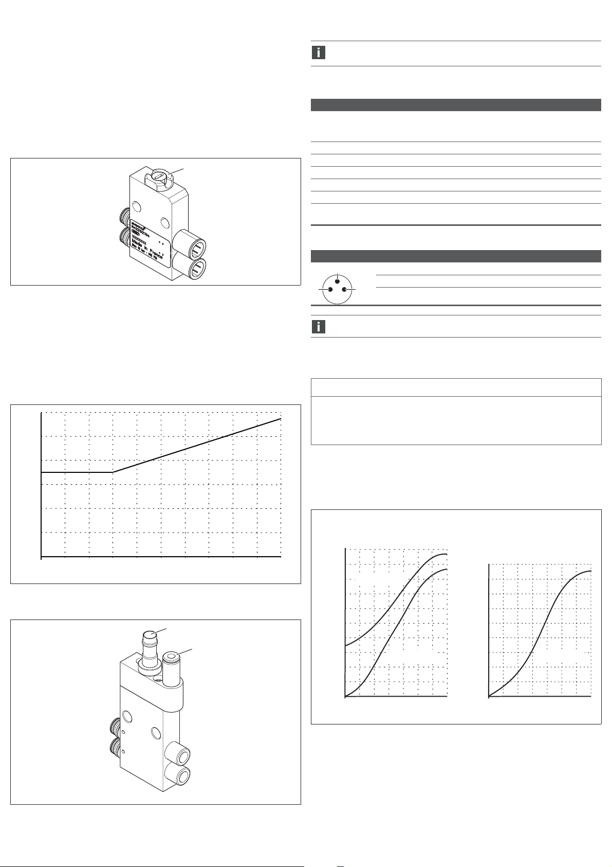
Abb. 9: Entlüftungsmodul
10 Anschluss für die Steuerluftleitung 11 Entlüftung
11
10
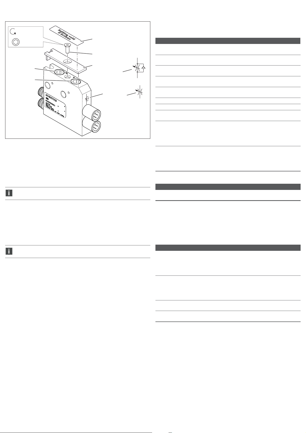
Abb. 10: Druckregelventil, zweikanalig und einkanalig
12 Manometeranschluss für Anschluss 2
13 Manometeranschluss für Anschluss 4
14 Verschlussstopfen
15 Manometer
16 Kontermutter
17 Einstellschraube für Anschluss 2
18 Einstellschraube für Anschluss 4
Absperrmodul: Arbeitsdruck sperren
Das Absperrmodul und der Luftkreislauf sollten monatlich getestet werden,
um deren korrekte Funktion sicherzustellen.
Page 7

AVENTICS | R422003121–BAL–001–AC | Deutsch 6
Manuell betätigtes Absperrmodul
Um die Arbeitsleitung abzusperren:
O Drehen Sie die Verriegelung (18) mit einem Schraubendreher um 45° gegen den
Uhrzeigersinn, bis sie herausspringt. Drehen Sie dann nochmals um 45° weiter.
O Sichern Sie ggf. die Verriegelung gegen unerlaubtes Betätigen mit einem
Sicherungskabel für Absperrventile (Materialnummer: 7472D02758) oder einem
Schloss. Der Lochdurchmesser beträgt 5 mm.
Um das Absperrmodul zu entriegeln:
O Entfernen Sie ggf. das Sicherungskabel für Absperrventile bzw. das Schloss.
O Drehen Sie die Verriegelung um 45° im Uhrzeigersinn, drücken Sie die
Verriegelung dann bis zum Anschlag ein und drehen Sie sie um weitere 45° im
Uhrzeigersinn bis zum Anschlag.
18
Abb. 11: Manuell betätigtes Absperrmodul
18 Verriegelung
Pneumatisch betätigte Absperrmodule sind auch mit Positionserkennung
verfügbar. Die Position können Sie über einen Sensor mit M8-Anschluss
abfragen.
Tabelle 4: Sensordaten
Elektrische Daten des Sensors
Verhalten Das Sensorsignal liegt an, wenn keine
Steuerluft an der Absperrung anliegt,
d. h. keine Luft durch die Arbeitsleitung
strömt.
Ausgang PNP
max. Stromaufnahme 15 mA
Spannungsbereich min./max. 10…30 V
kurzschlusssicher ja
Spannungsverlust < 2,5 V
Schutzart nach EN 60529/IEC 529 IP 67 bei montiertem Anschluss
Tabelle 5: Pinbelegung des Sensoranschlusses
Pin Belegung
4
10V
4Ausgang
1
3
3+Vs
Die Ausrichtung der Pins hängt von der Winkelposition des Sensors ab.
Pneumatisch betätigtes Absperrmodul
Um die Arbeitsleitung freizugeben:
O Beaufschlagen Sie zur Betätigung des Absperrmoduls den Steuerluftanschluss
mindestens mit dem in Abb. 12 dargestellten Mindestdruck P2, der dem Druck an
den Anschlüssen 2 oder 4 entspricht.
6
5
4
3
2
Steuerdruck P2 [bar]
1
0
012345678910
Arbeitsdruck [bar]
Abb. 12: Arbeitsdruckdiagramm des pneumatisch betätigten Absperrmoduls
19
20
Drosselmodul: Drosselung einstellen
ACHTUNG
Gefahr durch Überdrehen der Einstellschraube!
Beschädigung des Drosselmoduls!
O Drehen Sie die Einstellschraube niemals fest in den Anschlag hinein
(maximales Anzugsmoment: 0,5 Nm).
Drosselmodule gibt es in den Ausführungen unidirektional und bidirektional. Sie
erkennen Ihre Ausführung am Symbol (23) auf der Vorderseite.
Die Arbeitsleitungen 2 und 4 können Sie unabhängig voneinander reduzieren.
Um den Durchfluss in der Arbeitsleitung einzustellen, müssen Sie die
Einstellschraube für die Anschlüsse 2 bzw. 4 einstellen.
unidirektionaler Durchfluss am
Anschluss 2 und 4 (±20%)
(R422003267)
500
450
400
unreguliert
350
300
250
200
150
Durchfluss [Nl/min]
100
50
0
01234567
reguliert reguliert
bidirektionaler Durchfluss am
Anschluss 2 und 4 (±20%)
(R422003578)
450
400
350
300
250
200
150
Durchfluss [Nl/min]
100
50
0
01234567
Anzahl UmdrehungenAnzahl Umdrehungen
Abb. 13: Pneumatisch betätigtes Absperrmodul
19 Sensoranschluss M8x1 (optional) 20 Steuerluftanschluss Ø 4
Abb. 14: Durchflussdiagramme der Drosselmodule
1. Drehen Sie die Einstellschraube (21, 22) mit einem Innensechskantschlüssel
5 mm gegen den Uhrzeigersinn, um den Durchfluss zu erhöhen.
Die Einstellung im Endanschlag entspricht maximal möglichen Durchfluss.
Drehen Sie die Einstellschraube im Uhrzeigersinn, um den Durchfluss zu
reduzieren.
2. Sichern Sie ggf. die Einstellschrauben mit einer Abdeckplatte (24) und/oder
einem Abdeckaufkleber (26).
Page 8

AVENTICS | R422003121–BAL–001–AC | Deutsch 7
10 Technische Daten
= 1,2 Nm ±0,2
SW 2,5
21
22
Abb. 15: Drosselmodul
21 Einstellschraube für Anschluss 2
22 Einstellschraube für Anschluss 4
23 Symbol für die Drosselungsart
24 Abdeckplatte zum Verhindern von
Veränderungen an den
Einstellschrauben
Das Drosselmodul und der Luftkreislauf sollten monatlich getestet werden,
um deren korrekte Funktion sicherzustellen.
25 Schraube zum Befestigen der
26 Abdeckaufkleber
27 Symbol für unidirektionale
28 Symbol für bidirektionale
26
25
24
23
Abdeckplatte
Durchflussrichtung
Durchflussrichtung
27
28
Tabelle 6: Allgemeine Daten
Allgemeine Daten
Temperaturbereich für
Anwendung
Temperaturbereich
Lagerung
Betriebsdruck min./max. 0–10 bar
Regelbereich des
Druckreglers
Einstellbereich des
Drosselmoduls
zulässiges Medium Druckluft
max. Partikelgröße 40 μm
Ölgehalt der Druckluft 0–5 mg/m
Der Drucktaupunkt muss mindestens 15 °C unter der Umgebungs- und
Mediumstemperatur liegen und darf max. 3 °C betragen.
Der Ölgehalt der Druckluft muss über die gesamte Lebensdauer konstant bleiben.
O Verwenden Sie ausschließlich von AVENTICS zugelassene Öle, siehe
Online-Katalog von AVENTICS, Kapitel „Technische Informationen“.
Einbaulage W Entlüftungsmodule, Druckregelventile,
Tabelle 7: Normen und Richtlinien
berücksichtigte Normen und Richtlinien
DIN EN ISO 4414 Fluidtechnik – Allgemeine Regeln und sicherheitstechnische
Anforderungen an Pneumatikanlagen und deren Bauteile
Weitere technische Daten finden Sie im Online-Katalog unter
www.aventics.com/pneumatics-catalog.
-10 °C bis 60 °C
–25 °C bis 80 °C
0,5–10 bar
siehe Abb. 14 „Durchflussdiagramme der
Drosselmodule“
3
Drosselmodule und pneumatisch betätigte
Absperrmodule:
beliebig bei trockener und ölfreier Druckluft
W manuell betätigte Absperrmodule: siehe Abb. 1
8 Entsorgung
O Befolgen Sie die nationalen Vorschriften zur Entsorgung.
9 Fehlersuche und Fehlerbehebung
Wenden Sie sich an eine der Kontaktadressen, die Sie unter
http://www.aventics.com/contact finden.
11 Ersatzteile und Zubehör
Ta be ll e 8: Zu be h ör
Beschreibung Materialnummer
Abdeckaufkleber (4 Stück):
verhindert die Manipulation der Drosselmodule.
Die Aufkleber können über die Stellschrauben geklebt
werden, um unbefugtes Verändern zu verhindern. Nach
dem Aufkleben lassen sich die Aufkleber nicht
zerstörungsfrei lösen.
Abdeckplatte (inkl. Schraube und 4 Abdeckaufklebern):
verhindert die Manipulation der Drosselmodule.
Die Abdeckplatte kann über den Einstellschrauben
befestigt werden, um unbefugtes Verändern zu vermeiden.
Die Abdeckaufkleber können Sie zusätzlich zur
Absicherung verwenden.
Verkettungsbausatz:
zur Verkettung von zweikanaligen Druckregelventilen
Montagewinkelbausatz:
zur Befestigung von Funktionsmodulen an der
Montageplatte
Weitere Hinweise zu Ersatzteilen und Zubehör finden Sie im Online-Katalog unter
www.aventics.com/pneumatics-catalog.
R422003596
R422003595
R422103090
R422103091
Page 9

AVENTICS | R422003121–BAL–001–AC | English 8
English
1 About this Documentation
Documentation validity
This documentation applies to the following function modules in the AV series for
mounting to AV valve systems and as a stand-alone variant:
W Exhaust modules
W Pressure regulators
W Shutoff modules
W Throttle modules
It is intended for installers, operators, service personnel, and system owners and
contains important information on the safe and proper installation, commissioning,
and operation of the product and how to remedy simple malfunctions yourself.
Additional documentation
O Only commission the product once you have obtained the following
documentation and understood and complied with its contents.
– R412015575, Notes on Safety
– R412018507, valve system assembly and connection, AV03/AV05
– System documentation (provided by the machine/system manufacturer and
not included in the AVENTICS scope of delivery)
You can also find all instructions, with the exception of the system
documentation, on the CD R412018133.
Presentation of information
To allow you to begin working with the product quickly and safely, uniform safety
instructions, symbols, terms, and abbreviations are used in this documentation. For
better understanding, these are explained in the following sections.
Notes on safety
In this documentation, there are safety instructions before the steps whenever there
is a risk of personal injury or damage to equipment. The m easures described to avoid
these hazards must be followed. Safety instructions are set out as follows:
SIGNAL WORD
Hazard type and source
Consequences of non-observance
O Measures to avoid these hazards
W Safety sign: draws attention to the risk
W Signal word: identifies the degree of hazard
W Hazard type and source: identifies the hazard type and source
W Consequences: describes what occurs when the safety instructions are not
complied with
W Precautions: states how the hazard can be avoided
Table 1: Hazard classes according to ANSI Z 535.6-2006
DANGER
Indicates a hazardous situation which, if not avoided, will certainly result in death
or serious injury.
WARNING
Indicates a hazardous situation which, if not avoided, could result in death or
serious injury.
CAUTION
Indicates a hazardous situation which, if not avoided, could result in minor or
moderate injury.
NOTICE
Indicates that damage may be inflicted on the product or the environment.
Symbols
The following symbols indicate information that is not relevant for safety but that
helps in comprehending the documentation.
Table 2: Meaning of the symbols
Symbol Meaning
If this information is disregarded, the product cannot be used or
operated optimally.
Table 2: Meaning of the symbols
Symbol Meaning
1.
2.
3.
Numbered steps:
The numbers indicate sequential steps.
Abbreviations
This documentation uses the following abbreviations:
Table 3: Abbreviations
Abbreviation Meaning
AV Advanced Valve
2 Notes on safety
About this chapter
The product has been manufactured according to the accepted rules of current
technology. Even so, there is risk of injury and damage to equipment if the following
chapter and safety instructions of this documentation are not followed.
O Read these instructions completely before working with the product.
O Keep this documentation in a location where it is accessible to all users at all
times.
O Always include the documentation when you pass the product on to third parties.
Intended use
The function modules are pneumatic devices that are attached to an AV valve system
or used as a stand-alone device together with pneumatic valves.
The function modules are intended for professional use only and not for private use.
The function modules may only be used for industrial applications.
O Use within the limits listed in the technical data.
O Only use compressed air as the medium. Operation with pure oxygen is not
permitted.
Improper use
Improper use of the product includes:
W Using the function modules for any application not stated in these instructions,
W Using the function modules under operating conditions that deviate from those
described in these instructions,
W Use of the function modules as a safety component
W Using the function modules as a pressure relief valve within the meaning of the
ISO 4414 standard.
The user alone bears the risks of improper use of the product.
Personnel qualifications
The work described in this documentation requires basic electrical and pneumatic
knowledge, as well as knowledge of the appropriate technical terms. In order to
ensure safe use, these activities may therefore only be carried out by qualified
technical personnel or an instructed person under the direction and supervision of
qualified personnel.
Qualified personnel are those who can recognize possible hazards and institute the
appropriate safety measures, due to their professional training, knowledge, and
experience, as well as their understanding of the relevant regulations pertaining to
the work to be done. Qualified personnel must observe the rules relevant to the
subject area.
General safety instructions
W
Observe the regulations for accident prevention and environmental protection.
W Observe the safety instructions and regulations of the country in which the
product is used or operated.
W Only use AVENTICS products that are in perfect working order.
W Follow all the instructions on the product.
W Only use accessories and spare parts approved by the manufacturer.
W Comply with the technical data and ambient conditions listed in these operating
instructions.
W If there is a malfunction, do not attempt unauthorized repairs. Instead, contact
your nearest AVENTICS sales office.
W You may only commission the product if you have determined that the end
product (such as a machine or system) in which the AVENTICS products are
installed meets the country-specific provisions, safety regulations, and
standards for the specific application.
O Individual, independent action
Page 10

AVENTICS | R422003121–BAL–001–AC | English 9
Safety instructions related to the product and
technology
CAUTION
Danger of injury due to loose PUR tubing!
The push-in fittings are only suitable for PUR tubing if you are using PUR tubing
from AVENTICS or if additional stiffener sleeves from other providers have been
inserted in the ends of the PUR tubing.
O Use only AVENTICS stiffener sleeves with the following material numbers for
PUR tubing from other providers:
8183040000 Ø 4 x 0.75 8183080000 Ø 8 x 1
8183060000 Ø 6 x 1
3 General Instructions on Equipment and
Product Damage
NOTICE
Mechanical loads!
Damage to function modules!
O Make sure that the function modules are not under mechanical strain.
Danger of injury if assembled under pressure or voltage!
Assembling when under pressure or electrical voltage can lead to injuries and
damage to the product or system components. Danger of injury from electric
shocks and sudden pressure drops.
O Make sure the relevant system part is not under pressure or voltage before
performing the following tasks:
– Disassembling/assembling the product
– Disassembling/assembling the system
O Protect the system against being restarted.
4 Delivery Contents
W 1 function module according to order
W 1 set of operating instructions
Additionally for pressure regulators, depending on the version
W 1 or 2 blanking plugs
W Pressure regulators: You can mechanically regulate the pressure on output
connections 2 and 4 of a valve on the pressure regulator and check it using a
pressure gauge.
– single-channel pressure regulators regulate one of the two output
connections: either output connection 2 or 4. The second output connections
is uncontrolled.
– Two-channel pressure regulators regulate both output connection 2 and 4.
W Shutoff modules: You can manually shut off output connections 2 and 4.
– You can lock manually operated shutoff modules to prevent unintentional
release.
– Pneumatically operated shutoff modules are available with and without
position detection.
W Throttle module: The throttle module can be used to mechanically reduce the
flow to output connections 2 and 4 of a valve independent of each other.
– Uni-directional throttle modules reduce the flow from the operating line to the
valve system. Due to a non-return valve, the flow from the valve system to the
operating line almost unreduced.
– Bi-directional throttle modules reduce the flow in both directions.
Product identification
O Check the part number on the rating plate to determine whether the function
module matches your order.
Mounting orientation
Exhaust modules, pressure regulators, throttle modules, and pneumatically
operated shutoff modules can have any mounting orientation if used with dry and
oil-free compressed air.
Manually operated shutoff modules must be fastened so that the lock points
upwards. A deviation of up to ±90° is permissible (see Fig. 1).
90°
90°
Fig. 1: Permissible mounting orientation for manually operated shutoff module
90°
90°
90°
90°
90°
90°
5 About This Product
Series AV function modules are pneumatic components, which extend the function
of the connected valve. Depending on the order, you can mount the function modules
on the working connections of the AV valve systems or use them as a stand-alone
device.
Devices to connect to AV valve systems have pneumatic push-in
fittings on the valve side, which are directly inserted into
connections 2 and 4 of the AV valve systems.
Stand-alone devices have pneumatic push-in fittings on the valve
side for the tubing connection.
W Exhaust modules: For 5/3 directional valves with closed center, outputs 2 and 4
are pressurized after switching in the center. If the actuator needs to be moved,
e.g. for installation, maintenance, or to release persons, you can exhaust the
operating lines by applying control pressure to the exhaust module.
When combined with vertical actuators, exhaust modules with exhaust or
pressure limitation may be used up to a maximum load of 15 kg as well as up to
a speed of Vmax<33mm/s.
6 Assembly
Function modules for assembly on AV valve systems and stand-alone
variants are mounted in a different order.
CAUTION
Danger of injury if assembled under pressure!
Assembling when under pressure can lead to injuries and damage to the product
or system components.
O Make sure that the relevant system part is not under voltage or pressure
before you assemble the product.
O Protect the system against being restarted.
Mounting the function module to the AV valve
system
Fig. 2 shows how to pneumatically connect a function module to a valve system
using an exhaust module as an example. All other function modules are connected
with the respective AV valve system in the corresponding way.
For the stand-alone variant you must connect the valve side connections on
the function module with the valve system using tubing.
1. Remove the retaining clip.
2. Remove the pneumatic push-in fittings.
3. Plug the function module with the two valve side connections 2 and 4 into the two
output connections on the valve.
4. Insert the retaining clip back into the base plate to fix the function module.
Page 11

1.
4.
3.
2.
AVENTICS | R422003121–BAL–001–AC | English 10
Connecting two-channel pressure regulators
6. Connect both operating lines to connections 2 and 4.
4
5
3
2
6
1.
Fig. 2: Mounting function modules (example: exhaust module for AV valve
systems)
Mounting and stacking the function modules
In order to mount function modules, you will need mounting bracket kit R422103091,
consisting of 2 mounting brackets (1) and 2x M4 countersunk screws (2).
1. Mount the valve system on a mounting surface.
2. Align the mounting bracket flush to the outer function modules and fix the
mounting brackets onto the mounting surface, each with two M4 countersunk
screws (3) (not included in scope of delivery).
Mounting two-channel pressure regulators
Only use countersunk screws otherwise it may not be possible to mount
adjacent operating lines.
3. Connect the two mounting brackets (1), each with one M4 countersunk screw (2)
(included in scope of delivery) with the pressure regulators.
Tightening torque 1.2±0.2 Nm
Stacking two-channel pressure regulators
You will need stacking assembly kit R422103090, consisting of 5 stacking assembly
plates and 6 oval-head screws, to stack the two-channel pressure regulators.
4. Place the stacking assembly plates (4) in the slot (6) on the top side of the
pressure regulators so that they cover half of the two pressure regulators each.
The stacking assembly plates must interlock with each other.
5. Insert the oval-head screws (5) and tighten them.
Tightening torque: 0.7 ±0.1 Nm/tool: T8
1
3
2
1
Fig. 3: Mounting and stacking two-channel pressure regulators
1 Mounting bracket
2 Countersunk screw M4, in scope of delivery
3 Countersunk screw M4, not in scope of delivery
4 Stacking assembly plate
5 Oval-head screw
6 Slot
Mounting and stacking exhaust modules, shutoff modules,
throttle modules, and single-channel pressure regulators
NOTICE
Damage to property due to incorrect stacking assembly of function modules to
the AV valve systems!
When stacking exhaust modules, shutoff modules, throttle modules, and
single-channel pressure regulators to AV systems, they may be pressed together.
This means that the function modules on the AV valve connection are no longer
tight.
O Fix the function modules on the left and right with mounting brackets.
O Make sure that the function modules are not pulled together, but mounted
parallel to each other.
3. Mount both the mounting brackets on the function module with two M6 screws
(7) with nuts (8) (not included in scope of delivery). The screws are used as tie
rods.
This way the modules are stacked.
Page 12

AVENTICS | R422003121–BAL–001–AC | English 11
Connecting exhaust modules, shutoff modules, throttle
modules, and single-channel pressure regulators
4. Connect both operating lines to connections 2 and 4.
5. Exhaust module: Connect the pilot air to the pilot control connection.
3
8
1
7
3
1
Fig. 4: Mounting and stacking exhaust modules, shutoff modules, throttle
modules, and single-channel pressure regulators
3 Countersunk screw M4, not in scope of delivery
7 Screw M6, not included in scope of delivery
8 Nut M6, not included in scope of delivery
1 Mounting bracket
Mounting and stacking the stand-alone function
modules
Stacking two-channel pressure regulators
1. Place the pressure regulators next to each other so that both mounting pins (9)
reach into the corresponding holes in the neighboring valve.
2. Place the stacking assembly plates (4) in the slot (6) on the top side of the
pressure regulators so that they cover half of the two pressure regulators each.
The stacking assembly plates must interlock with each other.
3. Insert the oval-head screws (5) and tighten them.
Tightening torque: 0.7 ±0.1 Nm
Tool: T8
5
Mounting two-channel pressure regulators
In order to mount pressure regulators, will need mounting bracket kit R422103091,
consisting of 2 mounting brackets (1) and 2x M4 countersunk screws (2).
1. Fix the mounting brackets to the function module with one M4 countersunk screw
each (included in scope of delivery).
Tightening torque 1.2±0.2 Nm
2. Fix the mounting brackets on the mounting surface with two M4 countersunk
screws each (not included in scope of delivery).
Connecting two-channel pressure regulators
3. Connect both operating lines to connections 2 and 4.
3
2
2
1
3
1
Fig. 6: Mounting the two-channel pressure regulators on a mounting surface with
mounting brackets
1 Mounting bracket
2 Countersunk screw M4, in scope of delivery
3 Countersunk screw M4, not in scope of delivery
Mounting and stacking exhaust modules, shutoff modules,
throttle modules, and single-channel pressure regulators
To stack the exhaust modules, shutoff modules, and throttle modules you will need
two M6 screws with nuts (not included in scope of delivery). The screws are used as
tie rods. The length of the screws depends on the number of function modules.
1. Align the function modules parallel to each other. Position the mounting brackets
on the outside of the function modules.
2. Guide both M6 screws (7) through both the through holes on the mounting
brackets and function modules (see Fig. 7).
3. Place one M6 nut (8) on each of the two screws and tighten them.
Tightening torque: 1.2 ±0.2 Nm
4. Fix the two mounting brackets on the mounting surface with two M4 countersunk
screws each (not included in scope of delivery).
4
6
Fig. 5: Stacking two-channel pressure regulators
9 Fixing pins
4 Stacking assembly plate
5 Oval-head screw
6 Slot
Connecting exhaust modules, shutoff modules, throttle
modules, and single-channel pressure regulators
5. Connect both operating lines to connections 2 and 4.
6. Exhaust module: Connect the pilot air to the pilot control connection.
9
Page 13

18
14
17
12
15
16
16
13
15
14
12/13
12
16
17/18
AVENTICS | R422003121–BAL–001–AC | English 12
3
8
1
7
3
Fig. 7: Mounting and stacking exhaust modules, shutoff modules, throttle
modules, and single-channel pressure regulators
1 Mounting bracket
3 Countersunk screw M4, not in scope of delivery
7 Screw M6, not included in scope of delivery
8 Nut M6, not included in scope of delivery
7 Operation
Exhaust module: Exhausting the operating line
To exhaust the operating line:
O Apply at least the minimum pressure P2 illustrated in Fig. 8, which corresponds
with the pressure on connections 2 or 4, to the pilot control connection to operate
the exhaust module.
Pressure regulator: Setting the working pressure
CAUTION
Danger of injury due to escaping compressed air!
The pressure gauge connections are pressurized and must therefore always be
closed off with a pressure gauge or blanking plugs during operation.
O Only remove the pressure gauge or blanking plugs when no compressed air is
applied to the working connection.
NOTICE
Danger of overturning the adjustment screw!
Damage to the pressure regulator!
O Never turn the adjustment screw firmly all the way to the stop
(maximum tightening torque: 1 Nm).
The appropriate AV valve must be controlled so that you can set the working
pressure.
For single-channel pressure regulators, you can control the pressure either at
connection 2 or connection 4, depending on the version.
For two-channel pressure regulators, you can control the pressure at connection 2
and at connection 4 independent of each other.
To set the pressure in the operating line you must set the adjustment screws for
connections 2 or 4. The pressure in the operating line can be checked by mounting a
pressure gauge (12, 13) to the respective pressure gauge connections.
1. Replace the blanking plugs (14) with a pressure gauge (Ø 4) (15) if necessary.
2. Loosen the lock nut (16) on the adjustment screw (17, 18).
3. Turn the adjustment screw in a clockwise direction to increase the pressure.
The setting in the end stop corresponds with the unregulated working pressure.
Turn the adjustment screw in an anti-clockwise direction to reduce the pressure.
4. Retighten the lock nut once the required pressure has been set.
6
[bar]
5
P2
4
3
2
1
0
12345
0
Fig. 8: minimum pilot pressure depending on working pressure
The exhaust module and the air circuit should be tested monthly to ensure
they function correctly.
11
10
78910
6
P1
[bar]
Fig. 10: Pressure regulator, two-channel and single-channel
12 Pressure gauge connection for
connection 2
13 Pressure gauge connection for
connection 4
14 Blanking plug
15 Pressure gauges
16 Lock nut
17 Adjustment screw for connection 2
18 Adjustment screw for connection 4
Fig. 9: Exhaust module
10 Connection for the pilot air line 11 Exhaust
Shutoff module: Blocking the working pressure
The shutoff module and the air circuit should be tested monthly to ensure
they function correctly.
Page 14
1
4
3
AVENTICS | R422003121–BAL–001–AC | English 13
Manually operated shutoff module
To block the operating line:
O Use a screwdriver to turn the lock (18) 45° in an anticlockwise direction until it
releases. Then turn another 45°.
O If necessary, protect the lock against unintentional actuation with a cable lock for
shut-off valves (material number: 7472D02758) or a lock. The hole diameter is
5 mm.
To unlock the shutoff module:
O Remove the cable lock for shut-off valves or the lock.
O Tu rn th e lock 45° i n a cl ockwi se di recti on, t hen push the lock in up to th e end s top
and turn it another 45° in a clockwise direction up to the stop.
18
Fig. 11: Manually operated shutoff module
18 Lock
Pneumatically operated shutoff modules are also available with position
detection. A sensor with M8 connection can be used to query the position.
Table 4: Sensor data
Electrical data for the sensor
Behavior The sensor signal is supplied when no
pilot air is applied at the shutoff point, i.e.
no air flows through the operating line.
Output PNP
Max. current consumption 15 mA
Min./max. voltage range 10 to 30 V
Short-circuit proof Yes
Voltage drop < 2.5 V
Protection class according
IP67 for assembled connection
to EN 60529/IEC529
Table 5: Pin assignment for sensor connection
Pin Assignment
10V
4Output
3+Vs
Pin orientation depends on the sensor angle position.
Pneumatically operated shutoff module
To release the operating line:
O Apply at least the minimum pressure P2 illustrated in Fig. 12., which corresponds
with the pressure on connections 2 or 4, to the pilot control connection to operate
the shutoff module.
6
5
4
3
2
Control pressure P2 [bar]
1
0
012345678910
Working pressure [bar]
Fig. 12: Working pressure diagram for pneumatically operated shutoff module
19
20
Throttle module: adjusting the throttle
NOTICE
Danger of overturning the adjustment screw!
Damage to the throttle module!
O Never turn the adjustment screw firmly all the way to the stop (maximum
tightening torque: 0.5 Nm).
Throttle modules come in uni-directional and bi-directional versions. You can
identify the version by the symbol (23) on the front.
Operating lines 2 and 4 can be reduced independent of each other.
To set the flow in the operating line you must set the adjustment screws for
connections 2 or 4.
Uni-directional flow on connection 2
and 4 (±20%)
(R422003267)
500
450
400
Unregulated
350
300
250
200
Flow [std l/min]
150
100
50
0
01234567
Regulated Regulated
Bi-directional flow on connection 2
and 4 (±20%)
(R422003578)
450
400
350
300
250
200
Flow [std l/min]
150
100
50
0
01234567
Number of rotationsNumber of rotations
Fig. 13: Pneumatically operated shutoff module
19 Sensor connection M8x1 (optional) 20 Pilot control connection Ø 4
Fig. 14: Flow diagram for throttle module
1. Using an Allen key, turn the adjustment screw (21, 22) counterclockwise 5 mm to
increase the flow.
The setting in the end stop corresponds to the maximum possible flow.
Turn the adjustment screw in a clockwise direction to reduce the flow.
2. If necessary, secure the adjustment screw with a cover plate (24) and/or a cover
sticker (26).
Page 15
AVENTICS | R422003121–BAL–001–AC | EnglishAVENTICS | R422003121–BAL–001–AC | English 14
10 Technical Data
= 1,2 Nm ±0,2
SW 2,5
21
22
Fig. 15: Throttle module
21 Adjustment screw for connection 2
22 Adjustment screw for connection 4
23 Symbol for the type of throttle
24 Cover plate to prevent changes to the
adjustment screw
The throttle module and the air circuit should be tested monthly to ensure
they function correctly.
25 Screw to fasten the cover plate
26 Cover sticker
27 Symbol for uni-directional flow
28 Symbol for bi-directional flow
26
25
24
27
23
direction
direction
28
Tab le 6: Ge nera l da t a
General data
Operating temperature
range
Storage temperature
range
Working pressure
min./max.
Pressure regulator
adjustment range
Setting range of the
throttle module
Permissible medium Compressed air
Max. particle size 40 μm
Oil content of compressed
air
The pressure dew point must be at least 15°C below the ambient and medium
temperatures and must not exceed 3°C.
The oil content of compressed air must remain constant during the life cycle.
O Use only the approved oils from AVENTICS, see the AVENTICS online catalog,
chapter “Technical information”.
Mounting orientation W Exhaust modules, pressure regulators, throttle
Table 7: Standards and directives
Standards and directives complied with
DIN EN ISO 4414 Pneumatic fluid power – General rules and safety
requirements for systems and their components
-10°C to 60°C
–25°C to 80°C
0–10 bar
0.5–10 bar
See Fig. 14 “Flow diagram for throttle module”
0-5 mg/m
W Manually operated shutoff modules: see Fig. 1
3
modules, and pneumatically operated shutoff
modules:
Any if used with dry and oil-free compressed air
8 Disposal
O Comply with national regulations regarding disposal.
9Troubleshooting
Please contact one of the addresses found under
www.aventics.com/contact.
Further technical data can be found in our online catalog at
www.aventics.com/pneumatics-catalog.
11 Spare Parts and Accessories
Table 8: Accessories
Description Mat. no.
Cover sticker (4x):
Prevents manipulation to the throttle module.
The stickers can be placed over the adjustment screws to
prevent unauthorized changes. After positioning, the
stickers cannot be removed without destroying them.
Cover plate (incl. screw and 4 cover stickers):
Prevents manipulation to the throttle module.
The cover plate can be fastened over the adjustment screw
to prevent unauthorized changes. The cover stickers can be
used as additional protection.
Stacking assembly kit:
To stack two-channel pressure regulators
Mounting bracket kit:
To fasten function modules to the mounting plate
Further information on spare parts and accessories can be found in the online
catalog at www.aventics.com/pneumatics-catalog.
R422003596
R422003595
R422103090
R422103091
Page 16

AVENTICS | R422003121–BAL–001–AC | Français 15
Français
1 A propos de cette documentation
Validité de la documentation
La présente documentation est valable pour les modules de fonction de série AV
suivants pour un montage sur des îlots de distribution AV et en tant que variantes
Stand Alone :
W Modules d’échappement
W Régulateurs de pression
W Modules shut-off
W Modules d’étranglement
Elle est destinée aux monteurs, aux utilisateurs, au personnel de maintenance et aux
exploitants de l’installation. Elle contient des informations importantes pour
installer, mettre en service et utiliser le produit de manière sûre et conforme, ainsi
que pouvoir éliminer soi-même de simples interférences.
Documentations complémentaires
O Ne mettre le produit en service qu’en possession des documentations suivantes
et qu’après les avoir comprises et observées :
– R412015575, Consignes de sécurité
– R412018507, Montage et raccordement de l’îlot de distribution, AV03/AV05
– Documentation de l’installation (mise à disposition par le fabricant de la
machine / l’installation et non comprise dans la fourniture d’AVENTICS)
Toutes les instructions, en dehors de la documentation de l’installation, sont
également disponibles sur le CD R412018133.
Présentation des informations
Afin de pouvoir travailler rapidement et en toute sécurité avec ce produit, cette
documentation contient des consignes de sécurité, symboles, termes et abréviations
standardisés. Ces derniers sont expliqués dans les paragraphes suivants.
Consignes de sécurité
Dans la présente documentation, des consignes de sécurité figurent devant les
instructions dont l’exécution recèle un risque de dommages corporels ou matériels.
Les mesures décrites pour éviter des dangers doivent être respectées. Les
consignes de sécurité sont structurées comme suit :
MOT-CLE
Type et source de danger
Conséquences en cas de non-respect du danger
O Mesures pour éviter les dangers
W Signal de danger : attire l’attention sur un danger
W Mot-clé : précise la gravité du danger
W Type et source de danger : désigne le type et la source du danger
W Conséquences : décrit les conséquences en cas de non-respect
W Remède : indique comment contourner le danger
Tableau 1 : Classes de dangers selon la norme ANSI Z535.6-2006
DANGER
Signale une situation dangereuse entraînant à coup sûr des blessures graves ou
mortelles si le danger n’est pas évité.
AVERTISSEMENT
Signale une situation dangereuse susceptible d’entraîner des blessures graves ou
mortelles si le danger n’est pas évité.
ATTENTION
Signale une situation dangereuse susceptible d’entraîner des blessures légères à
modérées si le danger n’est pas évité.
REMARQUE
Dommages matériels : le produit ou son environnement peuvent être
endommagés.
Symboles
Les symboles suivants signalent des consignes qui ne relèvent pas de la sécurité
mais améliorent néanmoins l’intelligibilité de la documentation.
Tab leau 2 : Significatio n des symboles
Symbole Signification
En cas de non-respect de cette information, le produit ne livrera pas
sa performance optimale.
O Action isolée et indépendante
1.
2.
3.
Consignes numérotées :
Les chiffres indiquent l’ordre des différentes actions.
Abréviations
Cette documentation emploie les abréviations suivantes :
Tableau 3 : Abréviations
Abréviation Signification
AV Advanced Valve (distributeur avancé)
2 Consignes de sécurité
A propos de ce chapitre
Le produit a été fabriqué selon les règles techniques généralement reconnues. Des
dommages matériels et corporels peuvent néanmoins survenir si ce chapitre de
même que les consignes de sécurité ne sont pas respectés.
O Lire la présente documentation attentivement et complètement avant d’utiliser le
produit.
O Conserver cette documentation de sorte que tous les utilisateurs puissent y
accéder à tout moment.
O Toujours transmettre le produit à de tierces personnes accompagné des
documentations nécessaires.
Utilisation conforme
Les modules de fonction sont des appareils pneumatiques utilisés sur des îlots de
distribution AV ou en tant que variantes Stand Alone en lien avec des distributeurs
pneumatiques.
Les modules de fonction sont destinés à un usage dans le domaine professionnel et
non privé.
Utiliser les modules de fonction uniquement dans le domaine industriel.
O Respecter les limites de puissance indiquées dans les données techniques.
O Comme fluide, utiliser uniquement de l’air comprimé. L’utilisation d’oxygène pur
n’est pas autorisée.
Utilisation non conforme
Comptent parmi les utilisations non conformes du produit :
W Une utilisation des modules de fonction en dehors des domaines d’application
cités dans cette notice
W Une utilisation des modules de fonction déviant des conditions de
fonctionnement décrites dans cette notice
W Une utilisation des modules de fonction en tant que composant de sécurité
W Une utilisation des modules de fonction en tant que limiteur de pression au sens
de la norme ISO 4414
Toute utilisation non conforme est aux risques et périls de l’utilisateur.
Qualification du personnel
Les opérations décrites dans cette documentation exigent des connaissances
électriques et pneumatiques de base, ainsi que la connaissance des termes
techniques qui y sont liés. Afin d’assurer une utilisation en toute sécurité, ces travaux
ne doivent par conséquent être effectués que par des professionnels spécialement
formés ou par une personne instruite et sous la direction d’une personne
spécialisée.
Une personne spécialisée est capable de juger des travaux qui lui sont confiés, de
reconnaître d’éventuels dangers et de prendre les mesures de sécurité adéquates
grâce à sa formation spécialisée, ses connaissances et expériences, ainsi qu’à ses
connaissances des directives correspondantes. Elle doit respecter les règles
spécifiques correspondantes.
Consignes générales de sécurité
W
Respecter les consignes de prévention d’accidents et de protection de
l’environnement applicables.
W Respecter les prescriptions et dispositions de sécurité en vigueur dans le pays
d’utilisation / d’application du produit.
W Utiliser les produits AVENTICS exclusivement lorsque leur état technique est
irréprochable.
W Respecter toutes les consignes concernant le produit.
Page 17

AVENTICS | R422003121–BAL–001–AC | Français 16
W Utiliser uniquement des accessoires et des pièces de rechange autorisées par le
fabricant.
W Respecter les données techniques ainsi que les conditions ambiantes spécifiées
dans cette notice d’instruction.
W En cas de dysfonctionnement, ne procéder à aucune tentative de réparation et
contacter le service de vente AVENTICS le plus proche.
W Il n’est admis de mettre le produit en service que lorsqu’il a été constaté que le
produit final (par exemple une machine ou une installation) dans lequel les
produits AVENTICS sont utilisés satisfait bien aux dispositions du pays
d’utilisation, prescriptions de sécurité et normes de l’application.
Consignes de sécurité selon le produit et la
technique
ATTENTION
Risque de blessure dû au desserrage de flexibles en PU !
Les raccords instantanés ne conviennent à des flexibles en PU qu’en cas
d’utilisation de flexibles en PU AVENTICS ou d’insertion de douilles de support
supplémentaires aux extrémités de flexibles en PU d’autres fournisseurs.
O Pour les flexibles en PU d’autres fournisseurs, utiliser exclusivement les
douilles de support AVENTICS présentant les références suivantes :
8183040000 Ø 4 x 0,75 8183080000 Ø 8 x 1
8183060000 Ø 6 x 1
3 Consignes générales concernant les
dégâts matériels et les
endommagements du produit
REMARQUE
Contraintes mécaniques !
Endommagement des modules de fonction !
O Veiller à ce que les modules de fonction ne soient pas exposés à des
contraintes mécaniques.
Risque de blessure dû à un montage sous pression ou sous tension !
Le montage sous pression ou sous tension électrique en présence peut provoquer
des blessures et endommager le produit ou des parties de l’installation. Risque de
blessure dû à une chute de pression subite et une électrocution.
O Mettre la partie concernée de l’installation hors pression et hors tension avant
de réaliser les opérations suivantes :
– Montage / Démontage du produit
– Montage / Démontage du système
O Protéger l’installation de toute remise en marche.
W Modules d’échappement : pour les distributeurs 5/3 avec position centrale
fermée, les sorties 2 et 4 sont sous pression après toute commutation en position
centrale. Afin de pouvoir néanmoins déplacer l’actionneur, par ex. lors de
l’installation, de la maintenance ou de la libération de personnes, il est possible
de purger les conduites de service en alimentant le module d’échappement en
pression de pilotage.
En lien avec les actionneurs verticaux, il est possible d’utiliser des modules
d’échappement avec limiteur d’échappement ou de pression, charge maximale
de 15kg et vitesse Vmax <33mm/s.
W Régulateurs de pression : le régulateur de pression permet de réguler la
pression de manière mécanique aux raccords de sortie 2 et 4 d’un distributeur et
de la contrôler à l’aide d’un manomètre.
– Des régulateurs de pression à 1 canal permettent de réguler l’un des deux
raccords de sortie : le raccord 2 ou le raccord 4. Le deuxième raccord de
sortie n’est pas régulé.
– Les régulateurs de pression à 2 canaux permettent de réguler les raccords de
sortie 2 et 4.
W Modules shut-off : les modules shut-off permettent de bloquer les raccords de
sortie 2 et 4.
– Il est possible de verrouiller les modules shut-off à commande manuelle
contre tout déblocage involontaire.
– Les modules shut-off à commande pneumatique sont disponibles avec ou
sans détection de position.
W Modules d’étranglement : le module d’étranglement permet de réduire
mécaniquement le débit des raccords de sortie 2 et 4 d’un distributeur,
indépendamment l’un de l’autre.
– Les modules d’étranglement en version unidirectionnelle réduisent le débit de
la conduite de service à l’îlot de distribution. Le débit de l’îlot de distribution à
la conduite de service est quasiment inchangé en raison d’un clapet
anti-retour.
– Les modules d’étranglement en version bidirectionnelle réduisent le débit
dans les deux sens.
Identification du produit
O A l’aide de la référence figurant sur la plaque signalétique, vérifier que le module
de fonction correspond à la commande.
Position de montage
La position de montage des modules d’échappement, régulateurs de pression,
modules d’étranglement et modules shut-off à commande pneumatique est au choix
en cas d’air comprimé sec et non lubrifié.
Les modules shut-off à commande manuelle doivent être fixés de sorte que le
verrouillage soit dirigé vers le haut. Une différence allant jusqu’à ±90° est admise
(voir fig. 1).
90°
90°
90°
90°
4 Fourniture
W 1 module de fonction conformément à la commande
W 1 notice d’instruction
En supplément en cas de régulateurs de pression, selon la version
W 1 ou 2 bouchons d’obturation
5 A propos de ce produit
Les modules de fonction de série AV sont des composants pneumatiques
permettant d’étendre la fonction du distributeur raccordé. En fonction de la
commande, les modules de fonction peuvent être montés sur les raccords de service
des îlots de distribution AV ou utilisés en tant qu’appareils Stand Alone.
Les appareils destinés à être raccordés aux îlots de distribution
AV possèdent des raccords instantanés pneumatiques côté
distributeur pouvant être directement enfichés aux
raccordements 2 et 4 des îlots de distribution AV.
Les appareils Stand Alone possèdent des raccords instantanés
pneumatiques côté distributeur pour le raccord de tuyaux.
90°
Fig. 1: Positions de montage admises du module shut-off à commande manuelle
90°
90°
90°
6Montage
Les modules de fonction destinés au montage sur des îlots de distribution
AV et au fonctionnement en tant que variantes Stand Alone sont montés
dans un ordre différent.
ATTENTION
Risque de blessure dû à un montage sous pression !
Le montage sous pression peut provoquer des blessures et endommager le
produit ou des parties de l’installation.
O Mettre la partie pertinente de l’installation hors pression et hors tension avant
de monter le produit.
O Protéger l’installation de toute remise en marche.
Page 18

1.
4.
3.
2.
AVENTICS | R422003121–BAL–001–AC | Français 17
Montage du module de fonction sur un îlot de
distribution AV
La fig. 2 représente le raccordement pneumatique d’un module de fonction sur un
îlot de distribution à l’exemple d’un module d’échappement. Tous les autres modules
de fonction sont reliés de manière correspondante à l’îlot de distribution AV
respectif.
Pour la variante Stand Alone, les raccordements côté distributeur des
modules de fonction doivent être reliés à l’îlot de distribution à l’aide de
tuyaux.
1. Retirer l’étrier de retenue.
2. Retirer les raccords instantanés pneumatiques.
3. Enficher le module de fonction avec les deux raccords 2 et 4 côté distributeur aux
deux raccords de sortie du distributeur.
4. Afin de fixer le module de fonction, enficher l’étrier de retenue de nouveau dans
l’embase.
Raccordement de régulateurs de pression à deux canaux
6. Raccorder les deux conduites de service aux raccords 2 et 4.
4
5
3
2
1
1
Fig. 3: Fixation et combinaison des régulateurs de pression à deux canaux
1 Equerre de montage
2 Vis à tête conique M4, comprise dans la fourniture
3 Vis à tête conique M4, non comprise dans la fourniture
4 Tôle de combinaison
5 Vis à tête bombée
6 Rainure
6
3
2
1.
Fig. 2: Montage de modules de fonction (exemple : module d’échappement pour
îlots de distribution AV)
Fixation et combinaison de modules de fonction
Afin de fixer les modules de fonction, un kit R422103091 composé de 2 équerres de
montage (1) ainsi que 2 vis à tête conique M4 (2) est requis.
1. Fixer l’îlot de distribution sur une surface de montage.
2. Orienter les équerres de montage de manière affleurante aux modules de
fonction extérieurs et fixer les équerres de montage sur la surface de montage
avec deux vis à tête conique M4 (3) (non comprises dans la fourniture) chacune.
Fixation des régulateurs de pression à deux canaux
Utiliser exclusivement des vis à tête conique, sous peine de ne pas pouvoir
monter de conduites de service avoisinantes.
Fixation et combinaison de modules d’échappement, de
modules shut-off, de modules d’étranglement et de
régulateurs de pression à 1 canal
REMARQUE
Dommages matériels dus à une combinaison erronée des modules de fonction
aux îlots de distribution AV !
Lors de la combinaison de modules d’échappement, de modules shut-off, de
modules d’étranglement ou de régulateurs de pression à 1 canal avec les îlots AV,
une compression peut avoir lieu. Par conséquent, les modules de fonction ne sont
plus étanches au niveau du raccord du distributeur AV.
O Fixer les modules de fonction à gauche et à droite à l’aide d’équerres de
montage.
O Veiller à ne pas comprimer les modules de fonction, mais à les monter de
manière parallèle.
3. Fixer les deux équerres de montage au module de fonction à l’aide de deux vis M6
(7) avec écrous (8) (non comprises dans la fourniture). Ce faisant, les vis sont
utilisées en tant que tirants.
Les modules sont ainsi combinés.
3. Relier les deux équerres de montage (1) aux régulateurs de pression à l’aide
d’une vis à tête conique M4 (2) (comprise dans la fourniture) chacune.
Couple de serrage 1,2±0,2 Nm
Combinaison de régulateurs de pression à deux canaux
Afin de combiner les régulateurs de pression à deux canaux, un kit de combinaison
R422103090, composé de 5 tôles de combinaison et de 6 vis à tête bombée, est
requis.
4. Placer les tôles de combinaison (4) dans la rainure (6) sur la face supérieure des
régulateurs de pression, de sorte qu’elles recouvrent de moitié deux régulateurs
de pression.
Ce faisant, les tôles de combinaison doivent s’imbriquer entre elles.
5. Insérer les vis à tête bombée (5) et les serrer à fond.
Couple de serrage : 0,7 ±0,1 Nm/outil : T8
Page 19

AVENTICS | R422003121–BAL–001–AC | Français 18
Raccordement de modules d’échappement, de modules
shut-off, de modules d’étranglement et de régulateurs de
pression à 1 canal
4. Raccorder les deux conduites de service aux raccords 2 et 4.
5. Module d’échappement : raccorder l’air de pilotage au raccord d’air de pilotage.
3
8
1
7
3
1
Fig. 4: Fixation et combinaison de modules d’échappement, de modules shut-off,
de modules d’étranglement et de régulateurs de pression à 1 canal
3 Vis à tête conique M4, non comprise dans la fourniture
7 Vis M6, non comprise dans la fourniture
8 Ecrou M6, non compris dans la fourniture
1 Equerre de montage
Fixation et combinaison de modules de fonction
Stand Alone
Combinaison de régulateurs de pression à deux canaux
1. Placer les régulateurs de pression côte-à-côte de sorte que les deux goupilles
d’ajustage (9) s’imbriquent dans les alésages correspondants du distributeur
juxtaposé.
2. Placer les tôles de combinaison (4) dans la rainure (6) sur la face supérieure des
régulateurs de pression, de sorte qu’elles recouvrent de moitié deux régulateurs
de pression.
Ce faisant, les tôles de combinaison doivent s’imbriquer entre elles.
3. Insérer les vis à tête bombée (5) et les serrer à fond.
Couple de serrage : 0,7 ±0,1 Nm
Outil : T8
5
4
6
Fixation des régulateurs de pression à deux canaux
Afin de fixer les régulateurs de pression, un kit R422103091 composé de 2 équerres
de montage (1) et de 2 vis à tête conique M4 (2) est requis.
1. Fixer les équerres de montage au module de fonction à l’aide d’une vis à tête
conique M4 (comprise dans la fourniture) chacune.
Couple de serrage 1,2 ±0,2 Nm.
2. Fixer les équerres de montage sur la surface de montage avec deux vis à tête
conique M4 (non comprises dans la fourniture) chacune.
Raccordement de régulateurs de pression à deux canaux
3. Raccorder les deux conduites de service aux raccords 2 et 4.
3
2
2
1
3
1
Fig. 6: Fixation des régulateurs de pression à deux canaux à la surface de montage
à l’aide d’équerres de montage
1 Equerre de montage
2 Vis à tête conique M4, comprise dans la fourniture
3 Vis à tête conique M4, non comprise dans la fourniture
Combinaison et fixation de modules d’échappement,
de modules shut-off, de modules d’étranglement et de
régulateurs de pression à 1 canal
Afin de combiner des modules d’échappement, des modules shut-off et des modules
d’étranglement, deux vis M6 avec écrous (non comprises dans la fourniture) sont
requises. Ce faisant, les vis sont utilisées en tant que tirants. La longueur des vis
dépend du nombre de modules de fonction.
1. Orienter les modules de fonction parallèlement les uns aux autres. Positionner
les équerres de montage sur les côtés des modules de fonction.
2. Insérer les deux vis M6 (7) à travers les deux trous lisses des équerres de
montage et modules de fonction (voir fig. 7).
3. Placer un écrou M6 (8) sur chacune des deux vis et les serrer.
Couple de serrage : 1,2 ± 0,2 Nm.
4. Fixer les deux équerres de montage sur la surface de montage avec deux vis à
tête conique M4 (non comprises dans la fourniture) chacune.
Raccordement de modules d’échappement, de modules
shut-off, de modules d’étranglement et de régulateurs de
pression à 1 canal
5. Raccorder les deux conduites de service aux raccords 2 et 4.
6. Module d’échappement : raccorder l’air de pilotage au raccord d’air de pilotage.
Fig. 5: Combinaison de régulateurs de pression à deux canaux
9 Goupilles d’ajustage
4 Tôle de combinaison
5 Vis à tête bombée
6 Rainure
9
Page 20

0
0
1
2
3
4
5
6
12345
6
78910
[bar]
[bar]
P1
P2
18
14
17
12
15
16
16
13
15
14
12/13
12
16
17/18
AVENTICS | R422003121–BAL–001–AC | Français 19
3
8
1
7
3
Fig. 7: Combinaison et fixation de modules d’échappement, de modules shut-off,
de modules d’étranglement et de régulateurs de pression à 1 canal
1 Equerre de montage
3 Vis à tête conique M4, non comprise dans la fourniture
7 Vis M6, non comprise dans la fourniture
8 Ecrou M6, non compris dans la fourniture
7 Commande
Module d’échappement : purge de la conduite de
service
Pour purger la conduite de service :
O Pour activer le module d’échappement, alimenter le raccord d’air de pilotage
avec au moins la pression minimale P2 illustrée à la fig. 8 et correspondant à la
pression aux raccords 2 ou 4.
Régulateur de pression : réglage de la pression de
service
ATTENTION
Risque de blessure dû à l’échappement d’air comprimé !
Les raccords pour manomètre sont sous pression et doivent par conséquent
toujours être obturés par des manomètres ou des bouchons d’obturation lors du
fonctionnement.
O Ne retirer les manomètres ou les bouchons d’obturation qu’en l’absence d’air
comprimé au raccord de service.
REMARQUE
Danger dû à un vissage trop serré de la vis de réglage !
Endommagement du régulateur de pression !
O Ne jamais serrer la vis de réglage fermement jusqu’à la butée (couple de
serrage maximal : 1 Nm).
Afin de pouvoir régler la pression de service, le distributeur AV correspondant doit
être piloté.
Pour les régulateurs de pression à 1 canal, il est possible de réguler la pression sur
le raccord 2 ou 4 selon le type de construction.
Pour les régulateurs de pression à 2 canaux, il est possible de réguler la pression sur
les raccords 2 et 4, indépendamment l’un de l’autre.
Afin de régler la pression dans la conduite de service, la vis de réglage doit être
réglée pour les raccords 2 et/ou 4. Il est possible de contrôler la pression dans la
conduite de service après avoir monté des manomètres sur les raccords de
manomètre correspondants (12, 13).
1. Le cas échéant, remplacer les bouchons d’obturation (14) par des manomètres
(Ø 4) (15).
2. Dévisser le contre-écrou (16) de la vis de réglage (17, 18).
3. Afin d’augmenter la pression, tourner la vis de réglage dans le sens des aiguilles
d’une montre.
Le réglage en butée de fin de course correspond à une pression de service non
régulée.
Afin de réduire la pression, tourner la vis de réglage dans le sens inverse des
aiguilles d’une montre.
4. Resserrer le contre-écrou lorsque la pression souhaitée est atteinte.
Fig. 8: Pression minimale en fonction de la pression de service
Le module d’échappement et le circuit pneumatique doivent être testés
chaque mois afin de garantir un fonctionnement correct.
Fig. 9: Module d’échappement
10 Raccordement pour la conduite d’air
de pilotage
11
10
11 Echappement
Fig. 10: Régulateur de pression, à 1 et 2 canaux
12 Raccord pour manomètre pour
raccord 2
13 Raccord pour manomètre pour
raccord 4
14 Bouchons d’obturation
15 Manomètre
16 Contre-écrou
17 Vis de réglage pour raccord 2
18 Vis de réglage pour raccord 4
Page 21

AVENTICS | R422003121–BAL–001–AC | Français 20
Module shut-off : blocage de la pression de
service
Le module shut-off et le circuit pneumatique doivent être testés chaque mois
afin de garantir un fonctionnement correct.
Module shut-off à commande manuelle
Pour bloquer la conduite de service :
O A l’aide d’un tournevis, tourner le verrouillage (18) de 45° dans le sens inverse
des aiguilles d’une montre jusqu’à ce qu’il ressorte. Effectuer une nouvelle
rotation de 45°.
O Le cas échéant, sécuriser le verrouillage de toute activation non autorisée à l’aide
d’un câble de sécurisation pour vannes d’arrêt (référence : 7472D02758) ou d’un
verrou. Le diamètre du trou s’élève à 5 mm.
Pour déverrouiller le module shut-off :
O Le cas échéant, retirer le câble de sécurisation pour vannes d’arrêt ou le verrou.
O Tourner le verrouillage de 45° dans le sens des aiguilles d’une montre, puis
enfoncer le verrouillage jusqu’à la butée et le tourner de nouveau de 45° dans le
sens des aiguilles d’une montre jusqu’à la butée.
18
Fig. 11: Module shut-off à commande manuelle
18 Verrouillage
Module shut-off à commande pneumatique
Pour débloquer la conduite de service :
O Pour activer le module shut-off, alimenter le raccord d’air de pilotage avec au
m oi ns la pr es si on mi ni ma le P2 il lu st ré e à la fi g. 1 2 e t c or re sp on da nt à l a pr es si on
aux raccords 2 ou 4.
6
5
4
19
20
Fig. 13: Module shut-off à commande pneumatique
19 Raccord de capteur M8x1 (en option) 20 Raccord d’air de pilotage Ø 4
Les modules shut-off à commande pneumatique sont également disponibles
avec détection de position. La position peut être détectée par le biais d’un
capteur avec raccord M8.
Tableau 4 : Données du capteur
Données électriques du capteur
Comportement Le signal capteur est présent lorsque le
Sortie PNP
Puissance absorbée max. 15 mA
Plage de tension min./max. 10… 30 V
Protection contre les courts-circuits Oui
Perte de potentiel < 2,5 V
Indice de protection selon la norme
EN 60529 / CEI 529
Tableau 5 : Affectation des broches du raccord de capteur
Broche Affectation
4
1
10V
4Sortie
3
3+Vs
module shut-off n’est pas alimenté en air
de pilotage, c’est-à-dire que la conduite
de service n’est pas parcourue d’air.
IP 67 en cas de raccord monté
3
2
1
Pression de pilotage P2 [bar]
0
012345678910
Pression de service [bar]
Fig. 12: Diagramme de pression de service du module shut-off à commande
pneumatique
L’orientation des broches dépend de l’angle de positionnement du capteur.
Module d’étranglement : réglage de la limitation
REMARQUE
Danger dû à un vissage trop serré de la vis de réglage !
Endommagement du module d’étranglement !
O Ne jamais serrer la vis de réglage fermement jusqu’à la butée (couple de
serrage maximal : 0,5 Nm).
Les modules d’étranglement existent en version unidirectionnelle et
bidirectionnelle. La version est reconnaissable au symbole (23) sur la face avant.
Il est possible de réduire les conduites de service 2 et 4 indépendamment l’une de
l’autre.
Afin de régler le débit dans la conduite de service, la vis de réglage doit être réglée
pour les raccords 2 et/ou 4.
Page 22

AVENTICS | R422003121–BAL–001–AC | Français 21
Débit unidirectionnel aux raccords 2
et 4 (± 20 %)
(R422003267)
500
450
Débit [Nl/min]
400
350
300
250
200
150
100
50
0
Sans
Avec Avec
01234567
Débit bidirectionnel aux raccords 2
et 4 (± 20 %)
(R422003578)
450
400
350
300
250
200
Débit [Nl/min]
150
100
50
0
01234567
Nombre de rotationsNombre de rotations
Fig. 14: Diagrammes de débit des modules d’étranglement
1. Afin d’augmenter le débit, tourner la vis de réglage (21, 22) dans le sens inverse
des aiguilles d’une montre à l’aide d’une clé à six pans creux de 5 mm.
Le réglage en butée de fin de course correspond au débit maximal possible.
Afin de réduire le débit, tourner la vis de réglage dans le sens des aiguilles d’une
montre.
2. Sécuriser le cas échéant les vis de réglage à l’aide d’une plaque de protection (24)
et/ou d’un autocollant de recouvrement (26).
10 Données techniques
Tableau 6 : Données générales
Données générales
Plage de températures
pour application
Plage de température,
stockage
Pression de service
min./max.
Plage de réglage du
régulateur de pression
Plage de réglage du
module d’étranglement
Fluide autorisé Air comprimé
Taille de particule max. 40 μm
Teneur en huile de l’air
comprimé
Le point de rosée de la pression doit être d’au moins 15 °C inférieur à la
température ambiante et à la température du fluide et doit être au max. de 3 °C.
La teneur en huile de l’air comprimé doit rester constante tout au long de la durée
de vie.
O Utiliser exclusivement les huiles autorisées par AVENTICS, voir catalogue en
ligne AVENTICS, chapitre « Informations techniques ».
Position de montage W Modules d’échappement, régulateurs de pression,
De –10 °C à 60 °C
De –25 °C à 80 °C
0–10 bar
0,5–10 bar
Voir fig. 14 « Diagrammes de débit des modules
d’étranglement »
0–5 mg/m
3
modules d’étranglement et modules shut-off à
commande pneumatique :
Au choix en cas d’air comprimé sec et non lubrifié
W Modules shut-off à commande manuelle :
voir fig. 1
= 1,2 Nm ±0,2
26
SW 2,5
25
21
24
27
22
23
Fig. 15: Module d’étranglement
21 Vis de réglage pour raccord 2
22 Vis de réglage pour raccord 4
23 Symbole pour le type de limitation
24 Plaque de protection pour empêcher
toute modification des vis de réglage
25 Vis pour la fixation de la plaque de
protection
26 Autocollant de recouvrement
27 Symbole de débit unidirectionnel
28 Symbole de débit bidirectionnel
Le module d’étranglement et le circuit pneumatique doivent être testés
chaque mois afin de garantir un fonctionnement correct.
8 Mise au rebut
O Respecter la réglementation nationale concernant l’élimination.
28
Tableau 7 : Normes et directives
Normes et directives prises en compte
DIN EN ISO 4414 Transmission pneumatique – Règles générales et exigences de
sécurité pour les systèmes et leurs composants
De plus amples données techniques sont disponibles dans notre catalogue en ligne
à l’adresse www.aventics.com/pneumatics-catalog.
11 Pièces de rechange et accessoires
Ta bl ea u 8 : Ac c es so ir es
Description Référence
Autocollant de recouvrement (4 pièces) :
Empêche toute manipulation des modules d’étranglement.
Il est possible de coller les autocollants sur les vis de
réglage pour empêcher toute modification non autorisée.
L’autocollant ne peut pas être décollé sans dommage.
Plaque de protection (avec vis et 4 autocollants de
recouvrement) :
Empêche toute manipulation des modules d’étranglement.
La plaque de protection peut être fixée sur les vis de
réglage pour empêcher toute modification non autorisée. Il
est également possible d’utiliser des autocollants pour une
protection supplémentaire.
Kit de combinaison :
Pour la combinaison de régulateurs de pression à deux
canaux.
Kit d’équerres de montage :
Pour la fixation de modules de fonction sur la plaque de
montage.
D’autres remarques relatives aux pièces de rechange et accessoires sont
disponibles dans le catalogue en ligne sur www.aventics.com/pneumatics-catalog.
R422003596
R422003595
R422103090
R422103091
9 Recherche et élimination de défauts
S’adresser à l’un des contacts figurant sur le site
http://www.aventics.com/contact.
Page 23

AVENTICS | R422003121–BAL–001–AC | Italiano 22
Italiano
1 Sulla presente documentazione
Validità della documentazione
Questa documentazione vale per i seguenti moduli funzionali della serie AV da
montare su sistemi valvole AV e come varianti stand-alone:
W Moduli di scarico
W Valvole riduttrici di pressione
W Moduli di blocco
W Moduli di strozzamento
È indirizzata a installatori, utenti, personale del Servizio Assistenza e gestori di
impianti e contiene informazioni importanti per installare, mettere in funzione e
azionare il prodotto e per riparare autonomamente piccoli guasti, nel rispetto delle
norme e della sicurezza.
Documentazione aggiuntiva
O Mettere in funzione il prodotto soltanto se si dispone della seguente
documentazione e dopo aver compreso e seguito le indicazioni:
– R412015575, indicazioni di sicurezza
– R412018507, montaggio e collegamento sistema valvole, AV03/AV05
– Documentazione dell'impianto (viene messa a disposizione dai costruttori di
macchine e di impianti e non è compresa nella fornitura di AVENTICS)
Tutte le istruzioni, ad eccezione della documentazione dell'impianto, si
trovano anche sul CD R412018133.
Tabella 2: Significato dei simboli
Simbolo Significato
O Fase operativa unica, indipendente
1.
2.
3.
Sequenza numerata:
Le cifre indicano che le fasi si susseguono in sequenza.
Abbreviazioni
In questa documentazione vengono utilizzate le seguenti abbreviazioni:
Tabella 3: Abbreviazioni
Abbreviazione Significato
AV Advanced Valve
2 Indicazioni di sicurezza
Sul presente capitolo
Il prodotto è stato realizzato in base alle regole della tecnica generalmente
riconosciute. Ciononostante sussiste il pericolo di lesioni personali e danni materiali,
qualora non vengano rispettate le indicazioni di questo capitolo e le indicazioni di
sicurezza contenute nella presente documentazione.
O Leggere la presente documentazione attentamente e completamente prima di
utilizzare il prodotto.
O Conservare la documentazione in modo che sia sempre accessibile a tutti gli
utenti.
O Cedere il prodotto a terzi sempre unitamente alle documentazioni necessarie.
Presentazione delle informazioni
Per consentire un impiego rapido e sicuro del prodotto, all'interno della presente
documentazione vengono utilizzati avvertenze di sicurezza, simboli, termini e
abbreviazioni unitari. Per una migliore comprensione questi sono illustrati nei
seguenti paragrafi.
Indicazioni di sicurezza
Nella presente documentazione determinate sequenze operative sono
contrassegnate da avvertenze di sicurezza, indicanti un rischio di lesioni a persone
o danni a cose. Le misure descritte per la prevenzione di pericoli devono essere
rispettate. Le avvertenze di sicurezza sono strutturate come segue:
PAROLA DI SEGNALAZIONE
Natura e fonte del pericolo
Conseguenze della non osservanza del pericolo
O Misure di protezione dal pericolo
W Simbolo di avvertenza: richiama l’attenzione sul pericolo
W Parola di segnalazione: indica la gravità del pericolo
W Tipo e fonte del pericolo: indica il tipo e la fonte di pericolo
W Conseguenze: descrive le conseguenze della non osservanza
W Protezione: indica come evitare il pericolo
Tabella 1: Classi di pericolo secondo ANSI Z535.6–2006
PERICOLO
Indica una situazione pericolosa che, se non evitata, provoca lesioni gravi o
addirittura la morte
AVVERTENZA
Indica una situazione pericolosa che, se non evitata, può provocare lesioni gravi o
addirittura la morte
ATTENZIONE
Indica una situazione pericolosa che, se non evitata, può provocare lesioni medie
o leggere
NOTA
Danni materiali: il prodotto o l’ambiente possono essere danneggiati.
Simboli
I seguenti simboli indicano note non rilevanti per la sicurezza, ma che aumentano
comunque la comprensione della documentazione.
Tabella 2: Significato dei simboli
Simbolo Significato
In caso di inosservanza di questa informazione il prodotto non può
essere utilizzato in modo ottimale.
Utilizzo a norma
I moduli funzionali sono apparecchi pneumatici che vengono montati su un sistema
valvole AV o utilizzati come apparecchio stand-alone in concomitanza con valvole
pneumatiche.
I moduli funzionali sono studiati per un uso professionale e non per un uso privato.
Impiegare i moduli funzionali esclusivamente in ambiente industriale.
O Rispettare i limiti di potenza riportati nei dati tecnici.
O Utilizzare come fluido esclusivamente aria compressa. Il funzionamento con
ossigeno puro non è consentito.
Utilizzo non a norma
Per uso non a norma del prodotto si intende
W l'impiego dei moduli funzionali al di fuori degli ambiti d’applicazione riportati in
queste istruzioni,
W l'impiego dei moduli funzionali in condizioni di funzionamento che deviano da
quelle riportate in queste istruzioni,
W l’impiego dei moduli funzionali come componente di sicurezza,
W l'impiego dei moduli funzionali come valvola limitatrice di pressione ai sensi della
norma ISO 4414.
I rischi in caso di uso non a norma sono interamente a carico dell’utente.
Qualifica del personale
Le attività descritte nella presente documentazione richiedono conoscenze di base
in ambito elettrico e pneumatico e conoscenze dei termini specifici appartenenti a
questi campi. Per garantire la sicurezza operativa, queste attività devono essere
eseguite esclusivamente da personale specializzato o da persone istruite sotto la
guida di personale specializzato.
Per personale specializzato si intendono coloro i quali, grazie alla propria
formazione professionale, alle proprie conoscenze ed esperienze e alle conoscenze
delle disposizioni vigenti, sono in grado di valutare i lavori commissionati,
individuare i possibili pericoli e adottare le misure di sicurezza adeguate.
Il personale specializzato deve rispettare le norme in vigore specifiche del settore.
Avvertenze di sicurezza generali
W
Osservare le prescrizioni antinfortunistiche e di protezione ambientale in vigore.
W Osservare le disposizioni e prescrizioni di sicurezza del paese in cui viene
utilizzato il prodotto.
W Utilizzare i prodotti AVENTICS esclusivamente in condizioni tecniche perfette.
W Osservare tutte le note sul prodotto.
W Utilizzare esclusivamente parti di ricambio e accessori approvati dal produttore.
W Rispettare i dati tecnici e le condizioni ambientali riportati nelle presenti
istruzioni di montaggio.
W Non tentare di riparare il prodotto in caso di anomalia, ma contattare il centro
vendite AVENTICS più vicino.
W Mettere in funzione il prodotto solo dopo aver stabilito che il prodotto finale (per
esempio una macchina o un impianto) in cui i prodotti AVENTICS sono installati
corrisponde alle disposizioni nazionali vigenti, alle disposizioni sulla sicurezza e
alle norme dell’applicazione.
Page 24

AVENTICS | R422003121–BAL–001–AC | Italiano 23
Avvertenze di sicurezza sul prodotto e sulla
tecnologia
CAUTELA
Pericolo di lesioni in caso di distacco dei tubi flessibili in PUR!
Gli attacchi ad innesto sono adatti solo per tubi flessibili PUR originali di
AVENTICS o se all'estremità di tubi di altri produttori vengono inseriti dei
manicotti di rinforzo supplementari.
O Per tubi flessibili PUR di altri fornitori utilizzare esclusivamente manicotti di
rinforzo AVENTICS con il seguente codice:
8183040000 Ø 4 x 0,75 8183080000 Ø 8 x 1
8183060000 Ø 6 x 1
3 Avvertenze generali sui danni materiali
e al prodotto
NOTA
Sollecitazioni meccaniche!
Danneggiamento dei moduli funzionali!
O Assicurarsi che i moduli funzionali non siano sottoposti a sollecitazione
meccanica.
Pericolo di lesioni dovuto a montaggio sotto pressione o tensione!
Il montaggio sotto pressione o con tensione elettrica applicata può provocare
lesioni e danneggiare il prodotto o parti dell'impianto. Pericolo di lesioni a causa di
scossa elettrica e di improvvisa caduta della pressione.
O Togliere sempre l’alimentazione elettrica e pneumatica della parte rilevante
dell’impianto prima di eseguire le seguenti attività:
– Smontare/montare il prodotto
– Smontare/montare il sistema
O Proteggere l'impianto da riaccensione.
W Valvole riduttrici di pressione: sulla valvola riduttrice di pressione può essere
regolata meccanicamente la pressione sugli attacchi di uscita 2 e 4 e controllata
con un manometro.
– Le valvole riduttrici di pressione monocanale regolano uno dei dei due attacchi
di uscita: il 2 o il 4. Il secondo attacco di uscita non è regolato.
– Le valvole riduttrici a due canali regolano sia l'attacco di uscita 2 che il 4.
W Moduli di blocco: con i moduli di blocco possono essere chiusi gli attacchi di
uscita 2 e 4.
– I moduli di blocco ad azionamento manuale possono essere chiusi a chiave
per evitare uno sblocco involontario.
– I moduli di blocco ad azionamento pneumatico sono disponibili con o senza
riconoscimento di posizione.
W Moduli di strozzamento: con il modulo di strozzamento è possibile ridurre
meccanicamente la portata sugli attacchi di uscita 2 e 4 di una valvola,
indipendentemente l'uno dall'altro.
– I moduli di strozzamento in esecuzione unidirezionale riducono la portata
della conduttura di servizio verso il sistema valvole. Il flusso dal sistema
valvole alla conduttura di servizio non viene praticamente ridotto a causa della
valvola antiritorno.
– I moduli di strozzamento in esecuzione bidirezionale riducono la portata in
entrambi le direzioni.
Identificazione del prodotto
O Controllare in base al numero di materiale sulla targhetta d'identificazione se il
modulo funzionale corrisponde alla vostra ordinazione.
Posizione di montaggio
La posizione di montaggio dei moduli di scarico, delle valvole riduttrici di pressione,
dei moduli di strozzamento e dei moduli di blocco ad azionamento pneumatico è a
scelta, in presenza di aria compressa secca e non lubrificata.
I moduli di blocco ad azionamento manuale devono essere montati con il bloccaggio
verso l'alto. È consentita una differenza fino a ±90° (vedere Fig. 1).
90°
90°
90°
90°
4Fornitura
W 1 modulo funzionale in base all'ordinazione
W 1 esemplare delle istruzioni per l'uso
Per valvole riduttrici di pressione inoltre, in base all'esecuzione
W 1 o 2 tappi di chiusura
5 Descrizione del prodotto
I moduli funzionali della serie AV sono componenti pneumatici che ampliano la
funzione della valvola collegata. A seconda dell'ordinazione, potete montare i moduli
funzionali agli attacchi di utilizzo dei sistemi valvole oppure utilizzarli come
apparecchi stand-alone.
Apparecchi per il collegame nto a sistemi valvole AV dispongon o di
attacchi ad innesto pneumatici sul lato valvola, che vengono
inseriti direttamente negli attacchi 2 e 4 dei sistemi AV.
Apparecchi stand-alone hanno attacchi ad innesto pneumatici sul
lato valvola da collegare al tubo flessibile.
W Moduli di scarico: nelle valvole 5/3 con posizione centrale chiusa, le uscite 2 e 4
sono sotto pressione dopo un azionamento in posizione centrale. Per potere
comunque muovere l'attuatore, p. es. per un'installazione, una manutenzione o
per liberare delle persone, le condutture di servizio possono essere scaricate,
alimentando il modulo di scarico con pressione di pilotaggio.
In combinazione con attuatori verticali, possono essere utilizzati moduli di
scarico con strozzamento dell'aria di scarico e della pressione e carico massimo
di 15 kg, nonché una velocità Vmax < 33 mm/s.
90°
Fig. 1: Posizioni di montaggio consentite del modulo di blocco ad azionamento
manuale
90°
90°
90°
6 Montaggio
I moduli funzionali per il montaggio su sistemi valvole AV e le varianti
stand-alone vengono installati in ordine diverso.
CAUTELA
Pericolo di lesioni dovuto al montaggio in pressione!
Il montaggio in pressione può provocare lesioni e danneggiare il prodotto o parti
dell’impianto.
O Togliere l’alimentazione elettrica e pneumatica della parte dell’impianto
rilevante prima di montare il prodotto.
O Proteggere l'impianto da riaccensione.
Montaggio del modulo funzionale sul sistema
valvole AV
Nella Fig. 2 è rappresentato il collegamento pneumatico di un modulo funzionale su
un sistema valvole sull'esempio di un modulo di scarico. Tutti gli altri moduli
funzionali vengono collegati in modo corrispondente con il rispettivo sistema
valvole AV.
Per le varianti stand-alone gli attacchi valvola dei moduli funzionali devono
essere collegati al sistema valvole con tubi flessibili.
1. Rimuovere le graffe di tenuta.
2. Rimuovere gli attacchi ad innesto pneumatici.
Page 25

1.
4.
3.
2.
AVENTICS | R422003121–BAL–001–AC | Italiano 24
3. Inserire il modulo funzionale con gli attacchi 2 e 4 sul lato valvola negli attacchi
di uscita della valvola.
4. Inserire nuovamente la graffa di tenuta nella piastra base per fissare il modulo
funzionale.
1.
Fig. 2: Montaggio dei moduli funzionali (esempio: modulo di scarico per sistemi
valvole AV)
Collegamento delle valvole riduttrici di pressione a due
canali
6. Collegare le due condutture di servizio agli attacchi 2 e 4.
4
5
3
2
1
1
Fig. 3: Fissaggio e concatenamento delle valvole riduttrici di pressione a due
canali
1 Angolare di montaggio
2 Vite a testa svasata M4, compresa nella fornitura
3 Vite a testa svasata M4, non compresa nella fornitura
4 Lamierino di concatenamento
5 Vite a testa bombata
6 Scanalatura
6
3
2
Fissaggio e concatenamento dei moduli funzionali
Per fissare i moduli funzionali è necessario il kit di angolari di
montaggio R422103091, composto da 2 angolari (1) e 2 viti a testa svasata M4 (2).
1. Fissare il sistema valvole su una superficie di montaggio.
2. Orientare gli angolari di montaggio a filo dei moduli funzionali esterni e fissarli
sulla superficie di montaggio con rispettivamente due viti a testa svasata M4 (3)
(non comprese nella fornitura).
Fissaggio delle valvole riduttrici di pressione a due canali
Utilizzare esclusivamente viti a testa svasata, altrimenti non possono essere
montate condutture di servizio adiacenti.
3. Collegare i due angolari di montaggio (1) alle valvole riduttrici di pressione con
una vite a testa svasata M4 ciascuno (2) (comprese nella fornitura).
Coppia di serraggio: 1,2±0,2 Nm
Concatenamento delle valvole riduttrici di pressione a due
canali
Per unire in batteria le valvole riduttrici di pressione a due canali è necessario il kit
di concatenamento R422103090, composto da 5 lamierini di concatenamen to e 6 viti
a testa bombata.
4. Inserire i lamierini (4) nella scanalatura (6) sul lato superiore delle valvole
riduttrici di pressione, in modo da coprire per metà due valvole.
I lamierini di concatenamento devono incastrarsi tra loro.
5. Inserire le viti a testa bombata (5) e stringerle.
Coppia di serraggio: 0,7 ±0,1 Nm/utensile: T8
Fissaggio e concatenamento di moduli di scarico, di blocco
e di strozzamento e di valvole riduttrici di pressione
monocanali
NOTA
Danni materiali in caso di concatenamento errato dei moduli funzionali sui
sistemi valvole AV!
Durante il concatenamento su sistemi valvole AV, i moduli di scarico, di blocco e di
strozzamento e le valvole riduttrici di pressione monocanali possono essere
schiacciati. In questo caso i moduli funzionali sull'attacco valvola AV possono non
essere più ermetici.
O Fissare i moduli funzionali a destra e a sinistra con angolari di montaggio.
O Assicurarsi che i moduli funzionali non vengano stretti, bensì montati
parallelamente l'uno all'altro.
3. Fissare entrambi gli angolari di montaggio sul modulo funzionale con due viti M6
(7) con dadi (8) (non compresi nella fornitura). Le viti assumono la funzione di
tiranti.
In questo modo i moduli sono concatenati.
Page 26

AVENTICS | R422003121–BAL–001–AC | Italiano 25
Collegamento di moduli di scarico, di blocco e di
strozzamento e di valvole riduttrici di pressione
monocanali
4. Collegare le due condutture di servizio agli attacchi 2 e 4.
5. Modulo di scarico: collegare l'aria di pilotaggio al rispettivo attacco pneumatico.
3
8
1
7
3
1
Fig. 4: Fissaggio e concatenamento di moduli di scarico, di blocco e di
strozzamento e di valvole riduttrici di pressione monocanali
3 Vite a testa svasata M4, non compresa nella fornitura
7 Vite M6, non compresa nella fornitura
8 Dado M6, non compreso nella fornitura
1 Angolare di montaggio
Concatenamento e fissaggio dei moduli funzionali
stand-alone
Concatenamento delle valvole riduttrici di pressione a due
canali
1. Posizionare le valvole riduttrici di pressione una accanto all'altra, in modo che le
due spine di fissaggio (9) si inseriscano nei rispettivi fori della valvola adiacente.
2. Inserire i lamierini (4) nella scanalatura (6) sul lato superiore delle valvole
riduttrici di pressione, in modo da coprire per metà due valvole.
I lamierini di concatenamento devono incastrarsi tra loro.
3. Inserire le viti a testa bombata (5) e stringerle.
Coppia di serraggio: 0,7 ±0,1 Nm
Utensile: T8
5
Fissaggio delle valvole riduttrici di pressione a due canali
Per fissare le valvole riduttrici di pressione è necessario il kit di angolari di
montaggio R422103091, composto da 2 angolari (1) e 2 viti a testa svasata M4 (2).
1. Fissare gli angolari di montaggio al modulo funzionale con una vite a testa
svasata M4 ciascuno (compresa nelle fornitura).
Coppia di serraggio: 1,2±0,2 Nm
2. Fissare gli angolari sulla superficie di montaggio con rispettivamente due viti a
testa svasata M4 (non comprese nella fornitura).
Collegamento delle valvole riduttrici di pressione a due
canali
3. Collegare le due condutture di servizio agli attacchi 2 e 4.
3
2
2
1
3
1
Fig. 6: Fissaggio delle valvole riduttrici di pressione a due canali ad una superficie
di montaggio con appositi angolari
1 Angolare di montaggio
2 Vite a testa svasata M4, compresa nella fornitura
3 Vite a testa svasata M4, non compresa nella fornitura
Concatenamento e fissaggio di moduli di scarico, di blocco
e di strozzamento e di valvole riduttrici di pressione
monocanali
Per concatenare moduli di scarico, di blocco e di strozzamento sono necessarie due
viti M6 con dadi (non compresi nella fornitura). Le viti assumono la funzione di tiranti.
La lunghezza delle viti dipende dal numero di moduli funzionali.
1. Allineare i moduli funzionali paralleli gli uni agli altri. Posizionare gli angolari di
montaggio all'esterno sui moduli funzionali.
2. Inserire le due viti M6 (7) attraverso i fori passanti degli angolari di montaggio e
dei moduli funzionali (vedere Fig. 7).
3. Inserire su ognuna delle viti un dado M6 (8) e avvitarlo.
Coppia di serraggio: 1,2 ±0,2 Nm
4. Fissare i due angolari sulla superficie di montaggio con rispettivamente due viti
a testa svasata M4 (non comprese nella fornitura).
4
6
9
Fig. 5: Concatenamento delle valvole riduttrici di pressione a due canali
9 Spine di fissaggio
4 Lamierino di concatenamento
5 Vite a testa bombata
6 Scanalatura
Collegamento di moduli di scarico, di blocco e di
strozzamento e di valvole riduttrici di pressione
monocanali
5. Collegare le due condutture di servizio agli attacchi 2 e 4.
6. Modulo di scarico: collegare l'aria di pilotaggio al rispettivo attacco pneumatico.
Page 27

18
14
17
12
15
16
16
13
15
14
12/13
12
16
17/18
AVENTICS | R422003121–BAL–001–AC | Italiano 26
3
8
1
7
3
Fig. 7: Concatenamento e fissaggio di moduli di scarico, di blocco e di
strozzamento e di valvole riduttrici di pressione monocanali
1 Angolare di montaggio
3 Vite a testa svasata M4, non compresa nella fornitura
7 Vite M6, non compresa nella fornitura
8 Dado M6, non compreso nella fornitura
7Uso
Modulo di scarico: scarico della conduttura di
servizio
Per scaricare la conduttura di servizio:
O Per l'azionamento del modulo di scarico, alimentare l'attacco pneumatico di
pilotaggio con la pressione minima P2 rappresentata in Fig. 8, che corrisponde
alla pressione sugli attacchi 2 e 4.
Valvola riduttrice di pressione: regolazione della
pressione d'esercizio
CAUTELA
Pericolo di lesioni causate dall’aria compressa che fuoriesce!
Gli attacchi del manometro sono sottoposti a pressione e devono quindi essere
azionati solo con manometro collegato o con tappi di chiusura.
O Rimuovere il manometro o i tappi di chiusura sono in assenza di aria
compressa sull'attacco di utilizzo.
NOTA
Pericolo dovuto a serraggio eccessivo della vite di regolazione!
Danneggiamento della valvola riduttrice di pressione!
O Non stringere mai troppo la vite di regolazione nell'arresto (coppia di serraggio
massima: 1 Nm).
Per poter regolare la pressione d'esercizio, deve essere pilotata la valvola AV
corrispondente.
Nelle valvole riduttrici di pressione monocanale è possibile regolare la pressione
sull'attacco 2 o 4, in base al tipo di costruzione.
Nelle valvole riduttrici di pressione a due canali è possibile regolare la pressione sia
sull'attacco 2 che sull'attacco 4, indipendentemente l'uno dall'altro.
Per regolare la pressione nella conduttura di servizio è necessario muovere la vite
di regolazione sugli attacchi 2 e 4. La pressione nella conduttura di servizio può
essere controllata montando un manometro sui rispettivi attacchi (12, 13).
1. Sostituire eventualmente i tappi di chiusura (14) con un manometro (Ø 4) (15).
2. Svitare il controdado (16) sulla vite di regolazione (17, 18).
3. Ruotare la vite di regolazione in senso orario per aumentare la pressione.
La regolazione fino alla battuta corrisponde alla pressione d'esercizio
completamente aperta.
Ruotare la vite di regolazione in senso antiorario per diminuire la pressione.
4. Avvitare nuovamente il controdado quando è stata regolata la pressione
desiderata.
6
[bar]
P2
5
4
3
2
1
0
12345
0
Fig. 8: pressione di pilotaggio minima dipendente dalla pressione di esercizio
Il modulo di scarico e il circuito di ventilazione devono essere testati
mensilmente per assicurarne il funzionamento corretto.
Fig. 9: Modulo di scarico
10 Attacco per condotto dell'aria di
comando
11
10
11 Scarico
78910
6
P1
[bar]
Fig. 10: Valvola riduttrice di pressione, a due canali e monocanale
12 Attacco manometro per attacco 2
13 Attacco manometro per attacco 4
14 chiusure
15 Manometri
16 Controdado
17 Vite di regolazione per attacco 2
18 Vite di regolazione per attacco 4
Modulo di blocco: bloccaggio della pressione
d'esercizio
Il modulo di blocco e il circuito di ventilazione devono essere testati
mensilmente per assicurarne il funzionamento corretto.
Page 28

1
4
3
AVENTICS | R422003121–BAL–001–AC | Italiano 27
Modulo di blocco ad azionamento manuale
Per bloccare la conduttura di servizio:
O Ruotare il bloccaggio (18) di 45° con un cacciavite in senso antiorario fino a farlo
uscire fuori. Ruotarlo poi ancora di 45°.
O Proteggere il bloccaggio da un azionamento non consentito con un cavo di
sicurezza per valvole di blocco (codice: 7472D02758) o una serratura. Il diametro
del foro è di 5 mm.
Per sbloccare il modulo di blocco:
O Rimuovere eventualmente il cavo di sicurezza per valvole di blocco o la serratura.
O Ruotare il bloccaggio di 45° in senso orario, comprimerlo fino all'arresto per poi
ruotarlo di altri 45° fino all'arresto.
18
Fig. 11: Modulo di blocco ad azionamento manuale
18 Bloccaggio
Modulo di blocco ad azionamento pneumatico
Per lasciare libera la conduttura di servizio:
O Per l'azionamento del modulo di blocco, alimentare l'attacco pneumatico di
pilotaggio con la pressione minima P2 rappresentata in Fig. 12, che corrisponde
alla pressione sugli attacchi 2 e 4.
6
5
4
3
2
1
Pressione di pilotaggio P2 [bar]
0
012345678910
Pressione d'esercizio [bar]
Fig. 12: Diagramma della pressione di lavoro del modulo di blocco ad azionamento
pneumatico
19
20
I moduli di blocco ad azionamento pneumatico sono disponibili anche con
riconoscimento di posizione. La richiesta di posizione può essere effettuata
tramite un sensore con attacco M8.
Tab ella 4 : D ati s e nsore
Dati elettrici del sensore
Comportamento Il segnale sensore è presente se non è
applicata aria di pilotaggio al bloccaggio,
ossia se non scorre aria nella conduttura
di servizio.
Uscita PNP
Assorbimento di corrente max. 15 mA
Campo di tensione min./max. 10 …30 V
A prova di cortocircuito sì
Perdita di tensione < 2,5 V
Tipo di protezione secondo
IP 67 con attacco montato
EN 60529/IEC 529
Tabella 5: Occupazione pin dell'attacco sensore
Pin Occupazione
10V
4Uscita
3+Vs
L'allineamento dei pin dipende dalla posizione angolare del sensore.
Modulo di strozzamento: regolazione
NOTA
Pericolo dovuto a serraggio eccessivo della vite di regolazione!
Danneggiamento del modulo di strozzamento!
O Non stringere mai troppo la vite di regolazione nell'arresto (coppia di serraggio
massima: 0,5 Nm).
I moduli di strozzamento sono disponibili nelle esecuzioni unidirezionale e
bidirezionale. L'esecuzione si riconosce dal simbolo (23) sulla parte anteriore.
Le condutture di servizio 2 e 4 possono essere ridotte l'una indipendentemente
dall'altra.
Per regolare la portata nella conduttura di servizio è necessario muovere la vite di
regolazione sugli attacchi 2 e 4.
Portata unidirezionale sull'attacco 2
e 4 (±20%)
(R422003267)
500
450
400
non regolato
350
300
250
200
Portata [Nl/min]
150
100
50
0
01234567
regolato regolato
Portata bidirezionale sull'attacco 2
e 4 (±20%)
(R422003578)
450
400
350
300
250
200
Portata [Nl/min]
150
100
50
0
01234567
Numero di giriNumero di giri
Fig. 13: Modulo di blocco ad azionamento pneumatico
19 Attacco sensore M8x1 (opzionale) 20 Attacco pneumatico di pilotaggio Ø 4
Fig. 14: Diagrammi di flusso dei moduli di strozzamento
1. Ruotare la vite di regolazione (21, 22) con una chiave a brugola da 5 mm in senso
antiorario per aumentare la pressione.
La regolazione fino al finecorsa corrisponde alla portata massima possibile.
Ruotare la vite di regolazione in senso orario per diminuire la portata.
2. Proteggere event. le viti di regolazione con una piastra di copertura (24) e/o un
adesivo di copertura (26).
Page 29

AVENTICS | R422003121–BAL–001–AC | Italiano 28
10 Dati tecnici
= 1,2 Nm ±0,2
SW 2,5
21
22
Fig. 15: Modulo di strozzamento
21 Vite di regolazione per attacco 2
22 Vite di regolazione per attacco 4
23 Simbolo per il tipo di strozzamento
24 Piastra di copertura per impedire
modifiche alla vite di regolazione
26
25
24
27
23
25 Vite per il fissaggio della piastra di
copertura
26 Adesivo di copertura
27 Simbolo per la direzione di flusso
unidirezionale
28 Simbolo per la direzione di flusso
bidirezionale
28
Tab ella 6 : Dati generali
Dati generali
Campo temperatura per
applicazione
Campo temperatura
magazzinaggio
Pressione di esercizio
min./max.
Campo di regolazione del
riduttore di pressione
Campo di regolazione del
modulo di strozzamento
Fluido consentito Aria compressa
Dimensione max.
particella
Contenuto di olio dell’aria
compressa
Il punto di rugiada in pressione deve essere almeno 15 °C inferiore alla
temperatura ambiente e alla temperatura del fluido e deve essere al max. di 3 °C.
Il contenuto d’olio dell’aria compressa deve rimanere costante per tutta la durata.
O Utilizzare esclusivamente oli omologati AVENTICS, vedere il catalogo online di
AVENTICS, capitolo “Dati tecnici”.
Posizione di montaggio W Moduli di scarico, valvole riduttrici di pressione,
da -10 °C a 60 °C
da –25 °C a 80 °C
0–10 bar
0,5–10 bar
ved. Fig. 14 “Diagrammi di flusso dei moduli di
strozzamento”
40 μm
0–5 mg/m
W Moduli di blocco ad azionamento manuale: vedere
3
moduli di strozzamento e moduli di blocco ad
azionamento pneumatico:
a scelta in presenza di aria compressa non
lubrificata e secca
Fig. 1
Il modulo di strozzamento e il circuito di ventilazione devono essere testati
mensilmente per assicurarne il funzionamento corretto.
8 Smaltimento
O Seguire le norme nazionali per lo smaltimento.
9 Ricerca e risoluzione errori
Rivolgersi a uno degli indirizzi di contatto riportati al sito
http://www.aventics.com/contact.
Tabella 7: Norme e direttive
Norme e direttive rispettate
DIN EN ISO 4414 Pneumatica - Regole generali e requisiti di sicurezza per i
Per altri dati tecnici consultare il catalogo online alla pagina
www.aventics.com/pneumatics-catalog.
sistemi e i loro componenti
11 Parti di ricambio e accessori
Tabella 8: Accessori
Descrizione
Adesivo di copertura (4 pezzi):
impedisce la manipolazione delle valvole di strozzamento.
Gli adesivi possono essere attaccati sopra le viti per
impedire una modifica non autorizzata. Dopo l'incollaggio
non è possibile staccare gli adesivi senza romperli.
Piastra di copertura (comp. vite e 4 adesivi di copertura):
impedisce la manipolazione delle valvole di strozzamento.
La piastra di copertura può essere fissata sopra le viti di
regolazione per impedire una modifica non autorizzata. Gli
adesivi di copertura possono essere usati come misura
protettiva supplementare.
Kit di concatenamento:
Per il concatenamento di valvole riduttrici di pressione a
due canali
Kit di angolari di montaggio:
per il fissaggio di moduli funzionali alla piastra di
montaggio
Numero di
materiale
R422003596
R422003595
R422103090
R422103091
Per ulteriori indicazioni sulle parti di ricambio e sugli accessori consultare il catalogo
online all'indirizzo www.aventics.com/pneumatics-catalog.
Page 30

AVENTICS | R422003121–BAL–001–AC | Español 29
Español
1 Acerca de esta documentación
Validez de la documentación
Esta documentación es válida para los módulos funcionales siguientes de la serie AV
destinados al montaje en sistemas de válvulas AV o a uso como variante
Stand-Alone:
W Módulos de escape
W Válvulas reguladoras de presión
W Módulos de bloqueo
W Módulos de estrangulación
Va dirigida al personal operario y al personal de montaje y servicio, así como al
titular de la instalación, y contiene información importante para montar, poner en
servicio y utilizar el aparato de un modo seguro y apropiado, así como para eliminar
averías sencillas.
Documentación adicional
O No ponga el producto en funcionamiento mientras no disponga de la siguiente
documentación y haya entendido su contenido.
– R412015575, indicaciones de seguridad
– R412018507, montaje y conexión del sistema de válvulas, AV03/AV05
– Documentación de la instalación (debe ser facilitada por el fabricante de la
máquina/instalación y no se incluye en el volumen de suministro de AVENTICS)
Todas las instrucciones, con excepción de la documentación de la
instalación, están también disponibles en el CD R412018133.
Presentación de la información
Para poder trabajar con su producto de forma rápida y segura gracias a esta
documentación, en ella se emplean de forma coherente las indicaciones de
seguridad, símbolos, términos y abreviaturas. Para facilitar su comprensión, estos
se explican en las secciones siguientes.
Indicaciones de seguridad
En esta documentación se emplean instrucciones de seguridad antes de una
secuencia de acciones en la que existe riesgo de daños materiales y personales. Se
deben respetar las medidas descritas de protección ante peligros. Las indicaciones
de seguridad tienen la estructura siguiente:
PALABRA DE ADVERTENCIA
Tipo y fuente de peligro
Consecuencias si se ignora la advertencia de peligro
O Medidas para evitar situaciones de peligro
W Símbolo de advertencia: alerta sobre el peligro
W Palabra de advertencia: indica la gravedad del peligro.
W Clase y fuente de peligro: determina el tipo y la fuente de peligro
W Consecuencias: describe las consecuencias si no se sigue la indicación
W Protección: indica cómo evitar el peligro
Tabla 1: Clases de peligros según ANSI Z535.6-2006
PELIGRO
Identifica una situación de peligro con lesiones graves, incluso mortales, en caso
de que no se evite
ADVERTENCIA
Identifica una situación de peligro con riesgo de lesiones graves, incluso mortales,
en caso de que no se evite
ATENCIÓN
identifica una situación de peligro en la que puede existir riesgo de lesiones de
carácter leve o leve-medio
NOTA
Daños materiales: el entorno o el producto pueden sufrir daños.
Símbolos
Los símbolos siguientes identifican indicaciones que no son relevantes para la
seguridad, pero que ayudan a comprender mejor la documentación.
Tabla 2: Significado de los símbolos
Símbolo Significado
Si no se tiene en cuenta esta información, no se puede utilizar el
producto de forma óptima.
O Instrucción única, independiente
1.
2.
3.
Sucesión numerada de actuaciones:
Las cifras indican la secuencia de ejecución.
Abreviaturas
En esta documentación se utilizan las siguientes abreviaturas:
Tabla 3: Abreviaturas
Abreviatura Significado
AV Advanced Valve (válvula avanzada)
2 Indicaciones de seguridad
Acerca de este capítulo
Este producto ha sido fabricado conforme a las reglas de la técnica generalmente
conocidas. No obstante, existe riesgo de sufrir daños personales y materiales si no
se tienen en cuenta este capítulo ni las indicaciones de seguridad contenidas en la
documentación.
O Lea esta documentación con detenimiento y por completo antes de trabajar con
el producto.
O Guarde esta documentación en un lugar al que siempre puedan acceder
fácilmente todos los usuarios.
O Entregue el producto a terceros siempre junto con la documentación necesaria.
Utilización conforme a las especificaciones
Los módulos funcionales son aparatos neumáticos que se utilizan en combinación
con válvulas neumáticas, bien integrados en un sistema de válvulas AV, bien como
aparatos Stand-Alone.
Los módulos funcionales están diseñados para uso profesional y no para uso
privado.
Los módulos funcionales únicamente se pueden emplear en el ámbito industrial.
O Respete los límites de potencia mencionados en los datos técnicos.
O Como medio, únicamente se puede utilizar aire comprimido. No está permitido el
uso con oxígeno.
Utilización no conforme a las especificaciones
Dentro de la utilización no conforme a las especificaciones del producto se incluye:
W el uso de los módulos funcionales fuera de los campos de aplicación que se
especifican en estas instrucciones,
W el uso de los módulos funcionales en condiciones de funcionamiento que difieren
de las que se describen en estas instrucciones,
W el uso de los módulos funcionales como componentes de seguridad,
W el uso de los módulos funcionales como válvula limitadora de presión conforme
a la norma ISO 4414.
Los riesgos derivados de una utilización no conforme a las especificaciones son
responsabilidad exclusiva del usuario.
Cualificación del personal
Las actividades descritas en esta documentación requieren disponer de
conocimientos básicos de electrónica y neumática, así como de la terminología
correspondiente. Para garantizar un uso seguro, solamente el personal cualificado
o bien otra persona supervisada por una persona cualificada podrá realizar estas
actividades.
Por personal cualificado se entiende una persona que, en virtud de su formación
especializada, sus conocimientos y experiencia, así como su conocimiento acerca de
las normas vigentes, puede evaluar los trabajos que se le han encomendado,
detectar potenciales peligros y adoptar medidas de seguridad adecuadas. Un
especialista debe cumplir las reglas pertinentes específicas del ramo.
Indicaciones de seguridad generales
W
Observe la normativa vigente sobre prevención de accidentes y protección del
medio ambiente.
W Tenga en cuenta las normativas y disposiciones de seguridad vigentes en el país
de utilización del producto.
W Utilice los productos de AVENTICS solo si no presentan problemas técnicos.
W Tenga en cuenta todas las indicaciones que figuran en el producto.
W Utilice solo las piezas de repuesto y accesorios autorizados por el cliente.
Page 31

AVENTICS | R422003121–BAL–001–AC | Español 30
W Respete los datos técnicos y condiciones ambientales que se especifican en este
manual de instrucciones.
W En caso de producirse un fallo, no intente realizar reparaciones por cuenta
propia; en su lugar, póngase en contacto con el centro de ventas AVENTICS más
cercano.
W El producto no se puede poner en funcionamiento mientras no se haya verificado
que el producto final (por ejemplo, una máquina o instalación) en la que están
integrados los productos de AVENTICS cumple las disposiciones, normativas de
seguridad y normas de utilización vigentes en el país de explotación.
Indicaciones de seguridad según producto y
tecnología
PRECAUCIÓN
Peligro de lesiones por desprendimiento de mangueras de PUR.
Los racores instantáneos solo son aptos para las mangueras de PUR si se utilizan
mangueras de PUR de AVENTICS o, en caso de usar mangueras de otros
fabricantes, si se introducen casquillos de refuerzo adicionales en los extremos.
O Utilice para las mangueras de PUR de otros fabricantes únicamente los
casquillos de refuerzo de AVENTICS con los números de material siguientes:
8183040000 Ø 4 x 0,75 8183080000 Ø 8 x 1
8183060000 Ø 6 x 1
3 Indicaciones generales sobre daños
materiales y en el producto
NOTA
Cargas mecánicas.
Daño de los módulos funcionales.
O Asegúrese de que los módulos funcionales no se vean sujetos a cargas
mecánicas.
Peligro de lesiones por montaje con presión o tensión.
El montaje con presencia de tensión eléctrica o presión puede provocar lesiones o
dañar el producto y otros componentes de la instalación. Peligro de lesiones por
descarga eléctrica o caída de presión repentina.
O Desconecte la presión y la tensión de la parte de la instalación que
corresponda antes de ejecutar las tareas siguientes:
– Desmontar/montar el producto
– Desmontar/montar el sistema
O Disponga medios de bloqueo para impedir que la instalación se pueda
conectar.
W Módulos de escape: en las válvulas distribuidoras 5/3 con posición central
cerrada, las salidas 2 y 4 se encuentran bajo presión al conmutar a la posición
central. No obstante, si se desea mover el actuador, p. ej., para trabajos de
instalación, mantenimiento o para liberar a personas, puede purgar los
conductos de trabajo aplicando presión de pilotaje al módulo de escape.
En combinación con actuadores verticales, los módulos de escape se pueden
utilizar con estrangulamiento de aire de escape y presión, carga máxima de
15 kg y hasta una velocidad Vmáx. < 33 mm/s.
W Válvulas reguladoras de presión: en la válvula reguladora de presión puede
regular mecánicamente la presión en las conexiones de salida 2 y 4 de una
válvula, así como controlarla mediante un manómetro.
– Las válvulas reguladoras de presión de un canal regulan una de las dos
conexiones de salida: o bien la conexión de salida 2 o la 4. La segunda
conexión de salida queda sin regulación.
– Las válvulas reguladoras de presión de dos canales regulan tanto la conexión
de salida 2 como la 4.
W Módulos de bloqueo: los módulos de bloqueo le permite bloquear manualmente
las conexiones de salida 2 y 4.
– Puede además enclavar el módulo de bloqueo de accionamiento manual para
impedir que se desbloquee de forma inadvertida.
– Los módulos de bloqueo de accionamiento neumático están disponibles con y
sin detección de la posición.
W Módulos de estrangulación: con el módulo de estrangulación puede reducir
mecánicamente y de forma independiente el caudal en las conexiones de salida
2 y 4.
– Los módulos de estrangulación en versión unidireccional reducen el caudal
desde el conducto de trabajo hacia el sistema de válvulas. Debido a una
válvula antirretorno, el caudal del sistema de válvulas al conducto de trabajo
prácticamente no se reduce.
– Los módulos de estrangulación en versión bidireccional reducen el caudal en
ambas direcciones.
Identificación del producto
O Compruebe si el módulo funcional coincide con su pedido mediante el número de
material que se encuentra impreso en la placa de características.
Posición de montaje
La posición de montaje de los módulos de escape, las válvulas reguladoras de
presión, los módulos de estrangulación y los módulos de bloqueo de accionamiento
neumático es indiferente siempre y cuando se utilice aire comprimido seco y no
lubricado.
Los módulos de bloqueo de accionamiento manual se deben fijar de tal modo que el
enclavamiento quede hacia arriba. Se admite una divergencia de hasta ±90° (véase
la fig. 1).
90°
90°
90°
90°
4 Volumen de suministro
W 1 módulo funcional según pedido
W 1 manual de instrucciones de servicio
Con válvulas reguladoras de presión, adicionalmente, según la versión
W 1 o 2 tapones de cierre
5 Sobre este producto
Los módulos funcionales de la serie AV son componentes neumáticos que amplían
la función de la válvula conectada. En función del pedido, puede montar los módulos
funcionales en las conexiones de trabajo de los sistemas de válvulas AV o utilizarlos
como aparatos Stand-Alone.
Los aparatos destinados a conexión en sistemas de válvulas AV
tienen racores instantáneos neumáticos en el lado de la válvula
que se pueden insertar directamente en las conexiones 2 y 4 de
los sistemas de válvulas AV.
Los aparatos Stand-Alone presentan racores instantáneos
neumáticos en el lado de la válvula para conectar la manguera.
90°
Fig. 1: Posiciones de montaje válidas para el módulo de bloqueo de accionamiento
manual
90°
90°
90°
6Montaje
La secuencia de montaje difiere en los módulos funcionales destinados a
montaje en sistemas de válvulas AV y en las variantes Stand-Alone.
PRECAUCIÓN
Peligro de lesiones durante el montaje bajo presión.
Efectuar el montaje bajo presión puede provocar lesiones personales y daños en
el producto u otros componentes de la instalación.
O Desconecte la presión y la tensión de la pieza de la instalación relevante antes
de montar el producto.
O Disponga medios de bloqueo para impedir que la instalación se pueda
conectar.
Page 32
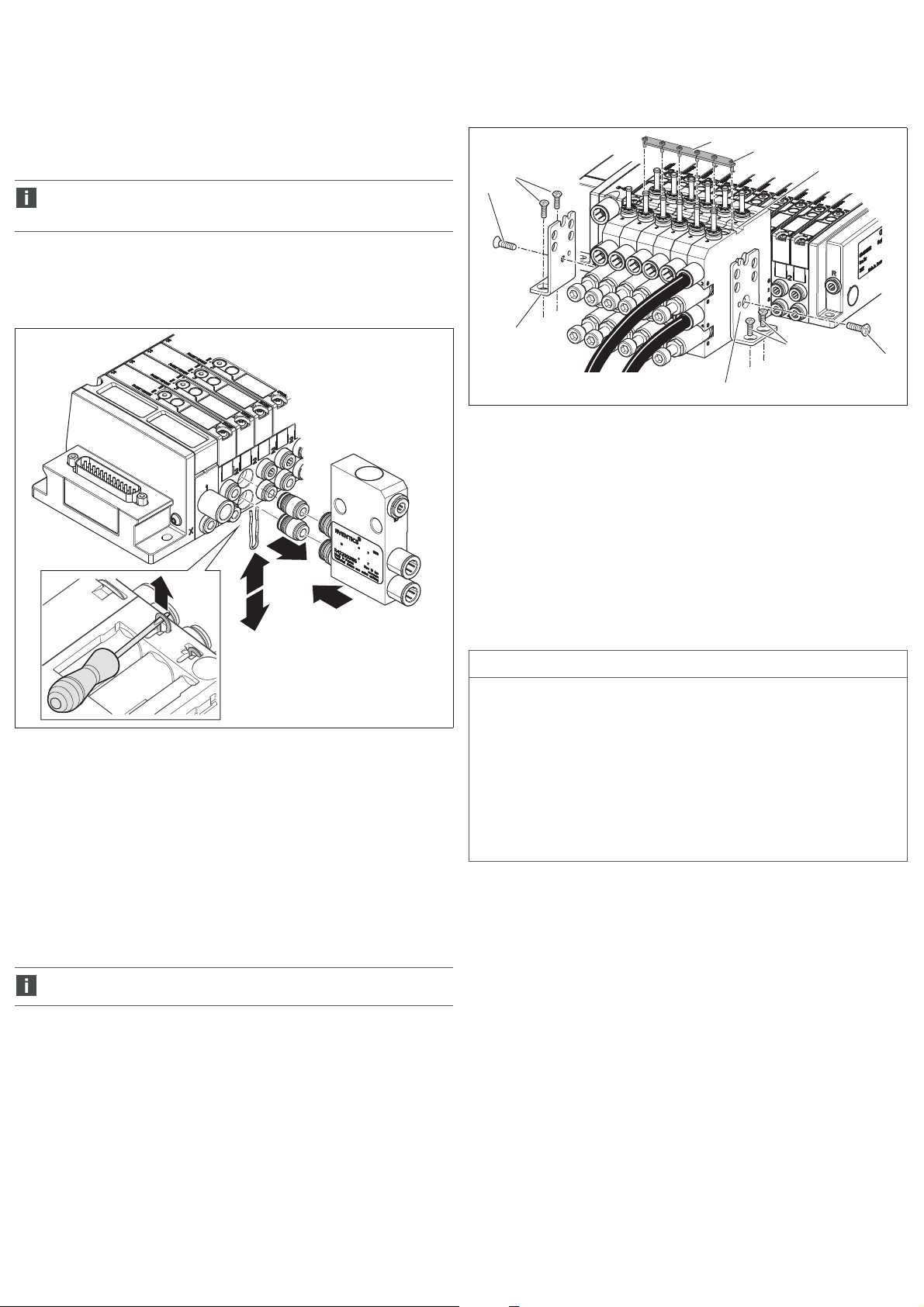
1.
4.
3.
2.
AVENTICS | R422003121–BAL–001–AC | Español 31
Montaje del módulo funcional en el sistema de
válvulas AV
En la figura 2 se representa la conexión neumática de un módulo funcional a un
sistema de válvulas tomando como ejemplo un módulo de escape. De modo análogo
se conectarán todos los demás módulos funcionales al correspondiente sistema de
válvulas AV.
En la variante Stand-Alone debe utilizar mangueras para empalmar las
conexiones del lado de válvula de los módulos funcionales al sistema de
válvulas.
1. Retire las grapas retén.
2. Retire los racores instantáneos neumáticos.
3. Conecte el módulo funcional con las dos conexiones 2 y 4 del lado de la válvula a
las dos conexiones de salida de la válvula.
4. Vuelva a insertar las grapas retén en la placa base para fijar el módulo funcional.
Conexión de las válvulas reguladoras de presión de dos
canales
6. Conecte los dos conductos de trabajo a las conexiones 2 y 4.
4
5
3
2
1
1
Fig. 3: Fijación y concatenación de las válvulas reguladoras de presión de dos
canales
1 Escuadra de montaje
2 Tornillo avellanado M4 (incluido en suministro)
3 Tornillo avellanado M4 (no incluido en suministro)
4 Chapa de concatenación
5 Tornillo alomado
6 Ranura
6
3
2
1.
Fig. 2: Montaje de módulos funcionales (ejemplo: módulo de escape para sistema
de válvulas AV)
Fijación y concatenación de módulos funcionales
Para fijar módulos funcionales necesita el juego de escuadras de montaje
R422103091 formado por 2 escuadras de montaje (
1. Fije el sistema de válvulas sobre una superficie de montaje.
2. Alinee las escuadras en los módulos funcionales exteriores de modo que queden
a ras y fíjelas a la superficie de montaje utilizando dos tornillos avellanados M4
por cada una (3) (no incluidos en el volumen de suministro).
Fijación de las válvulas reguladoras de presión de dos
canales
Utilice únicamente tornillos avellanados, ya que de lo contrario no se podrán
montar los conductos de trabajo adyacentes.
3. Fije las dos escuadras de montaje (1) con un tornillo avellanado M4 cada una (2)
(incluido en el volumen de suministro) a las válvulas reguladoras de presión.
Par de apriete 1,2±0,2 Nm
1
) y 2 tornillos avellanados M4 (2).
Fijación y concatenación de módulos de escape, módulos
de bloqueo, módulos de estrangulación y válvulas
reguladoras de presión de un canal
NOTA
Daños materiales por concatenación errónea de los módulos funcionales a los
sistemas de válvulas AV.
Al concatenar módulos de escape, módulos de bloqueo, módulos de
estrangulación y válvulas reguladoras de presión de un canal en sistemas AV,
existe el riesgo de que queden presionados unos contra otros. Esto provocaría
que los módulos funcionales de la conexión de válvula AV dejasen de ser
estancos.
O Fije los módulos funcionales a izquierda y derecha utilizando siempre
escuadras de montaje.
O Asegúrese de que los módulos funcionales no queden presionados unos
contra otros, sino montados en paralelo entre sí.
3. Fije las dos escuadras de montaje al módulo funcional utilizando dos tornillos M6
(7) y tuercas (8) (no incluidos en el volumen de suministro). Los tornillos actúan
de tirantes.
De este modo, se concatenan los módulos.
Concatenación de válvulas reguladoras de presión de dos
canales
Para concatenar válvulas reguladoras de presión de dos canales necesita el juego
de concatenación R422103090 formado por 5 chapas de concatenación y 6 tornillos
alomados.
4. Coloque las chapas de concatenación (4) en la ranura (6) situada en la parte
superior de las válvulas reguladoras de presión de modo que cada chapa cubra
la mitad de dos válvulas.
Las chapas de concatenación deben encajar entre sí.
5. Introduzca los tornillos alomados (5) y apriételos.
Par de apriete: 0,7 ±0,1 Nm/herramienta: T8
Page 33

AVENTICS | R422003121–BAL–001–AC | Español 32
Conexión de módulos de escape, módulos de bloqueo,
módulos de estrangulación y válvulas reguladoras de
presión de un canal
4. Conecte los dos conductos de trabajo a las conexiones 2 y 4.
5. Módulo de escape: conecte el aire de pilotaje a la conexión de aire de pilotaje.
3
8
1
7
3
1
Fig. 4: Fijación y concatenación de módulos de escape, módulos de bloqueo,
módulos de estrangulación y válvulas reguladoras de presión de un canal
Fijación de las válvulas reguladoras de presión de dos
canales
Para fijar válvulas reguladoras de presión necesita el juego de escuadras de
montaje R422103091 formado por 2 escuadras de montaje (1) y 2 tornillos
avellanados M4 (2).
1. Fije las escuadras de montaje al módulo funcional utilizando un tornillo
avellanado M4 por cada una (incluido en el volumen de suministro).
Par de apriete 1,2±0,2 Nm
2. Fije las escuadras a la superficie de montaje utilizando dos tornillos avellanados
M4 por cada una (no incluidos en el volumen de suministro).
Conexión de las válvulas reguladoras de presión de dos
canales
3. Conecte los dos conductos de trabajo a las conexiones 2 y 4.
3
2
2
1
3
3 Tornillo avellanado M4 (no incluido en suministro)
7 Tornillo M6 (no incluido en el volumen de suministro)
8 Tuerca M6 (no incluida en el volumen de suministro)
1 Escuadra de montaje
Concatenación y fijación de los módulos
funcionales Stand-Alone
Concatenación de válvulas reguladoras de presión de dos
canales
1. Coloque las válvulas reguladoras de presión una al lado de la otra de modo que
los pasadores de fijación (9) se introduzcan en los orificios correspondientes de
la válvula adyacente.
2. Coloque las chapas de concatenación (4) en la ranura (6) situada en la parte
superior de las válvulas reguladoras de presión de modo que cada chapa cubra
la mitad de dos válvulas.
Las chapas de concatenación deben encajar entre sí.
3. Introduzca los tornillos alomados (5) y apriételos.
Par de apriete: 0,7 ±0,1 Nm
Herramienta: T8
5
4
6
1
Fig. 6: Fijación de las válvulas reguladoras de presión de dos canales a una
superficie de montaje utilizando escuadras de montaje
1 Escuadra de montaje
2 Tornillo avellanado M4 (incluido en suministro)
3 Tornillo avellanado M4 (no incluido en suministro)
Fijación y concatenación de módulos de escape, módulos
de bloqueo, módulos de estrangulación y válvulas
reguladoras de presión de un canal
Para concatenar los módulos de escape, los módulos de bloqueo y los módulos de
estrangulación necesita dos tornillos M6 con sus correspondientes tuercas (no
incluidos en el volumen de suministro). Los tornillos actúan de tirantes. La longitud
de los tornillos depende de la cantidad de módulos funcionales.
1. Alinee los módulos funcionales en paralelo entre sí. Posicione las escuadras de
montaje por la parte exterior de los módulos funcionales.
2. Introduzca los dos tornillos M6 (7) por los orificios de las escuadras y de los
módulos funcionales (véase la fig. 7).
3. Coloque una tuerca M6 (8) en cada uno de ambos tornillos y apriételos.
Par de apriete: 1,2 ±0,2 Nm
4. Fije las dos escuadras a la superficie de montaje utilizando dos tornillos
avellanados M4 por cada una (no incluidos en el volumen de suministro).
Conexión de módulos de escape, módulos de bloqueo,
módulos de estrangulación y válvulas reguladoras de
presión de un canal
5. Conecte los dos conductos de trabajo a las conexiones 2 y 4.
6. Módulo de escape: conecte el aire de pilotaje a la conexión de aire de pilotaje.
9
Fig. 5: Concatenación de válvulas reguladoras de presión de dos canales
9 Pasadores de fijación
4 Chapa de concatenación
5 Tornillo alomado
6 Ranura
Page 34

0
0
1
2
3
4
5
6
12345
6
78910
[bar]
[bar]
P1
P2
18
14
17
12
15
16
16
13
15
14
12/13
12
16
17/18
AVENTICS | R422003121–BAL–001–AC | Español 33
3
8
1
7
3
Fig. 7: Fijación y concatenación de módulos de escape, módulos de bloqueo,
módulos de estrangulación y válvulas reguladoras de presión de un canal
1 Escuadra de montaje
3 Tornillo avellanado M4 (no incluido en suministro)
7 Tornillo M6 (no incluido en el volumen de suministro)
8 Tuerca M6 (no incluida en el volumen de suministro)
7Manejo
Módulo de escape: purga del conducto de trabajo
Para purgar el conducto de trabajo:
O Para accionar el módulo de escape, aplique a la conexión de aire de pilotaje la
presión mínima P2 que se representa en la fig. 8 y que corresponde a la presión
de las conexiones 2 o 4.
Válvula reguladora de presión: ajuste de la
presión de trabajo
PRECAUCIÓN
Peligro de lesiones por salida de aire comprimido.
Las conexiones del manómetro están bajo presión, por lo que durante el servicio
deben permanecer siempre tapadas mediante manómetros o tapones de cierre.
O Retire los manómetros o tapones de cierre solo cuando no haya aire
comprimido en la conexión de trabajo.
NOTA
Peligro por giro excesivo del tornillo de regulación.
Daño de la válvula reguladora de presión.
O
Nunca gire el tornillo de ajuste fijamente en el tope (par de apriete máx.: 1 Nm).
Para poder ajustar la presión de trabajo es necesario pilotar la válvula AV
correspondiente.
En las válvulas reguladoras de presión de un canal puede ajustar la presión,
dependiendo del tipo de construcción, en la conexión 2 o en la conexión 4.
En las válvulas reguladoras de presión de dos canales puede ajustar la presión
separadamente en la conexión 2 y en la conexión 4.
Para ajustar la presión en el conducto de trabajo, debe ajustar el tornillo de ajuste
para la conexión 2 o 4, según el caso. Puede comprobar la presión en el conducto
de trabajo montando manómetros en las correspondientes conexiones de
manómetro (12, 13).
1.
En caso necesario, sustituya los tapones de cierre (14) por manómetros (Ø 4) (15).
2. Afloje la contratuerca (16) del tornillo de ajuste (17, 18).
3. Gire el tornillo de ajuste en sentido horario para aumentar la presión.
El ajuste en el tope final corresponde a la presión de trabajo no regulada.
Gire el tornillo de ajuste en sentido antihorario para reducir la presión.
4. Apriete de nuevo la contratuerca una vez haya ajustado el valor de presión que
desee utilizar.
Fig. 8: presión de pilotaje mínima en función de la presión de funcionamiento
Se deben comprobar mensualmente el módulo de escape y el circuito de
aire para garantizar su correcto funcionamiento.
Fig. 9: Módulo de escape
10 Conexión para el conducto de aire de
pilotaje
11
10
11 Escape
Fig. 10: Válvula reguladora de presión, de dos canales y de un canal
12 Conexión de manómetro para
conexión 2
13 Conexión de manómetro para
conexión 4
14 Tapones de cierre
15 Manómetro
16 Contratuerca
17 Tornillo de ajuste para conexión 2
18 Tornillo de ajuste para conexión 4
Page 35

AVENTICS | R422003121–BAL–001–AC | Español 34
Módulo de bloqueo: bloqueo de la presión de
trabajo
Se deben comprobar mensualmente el módulo de bloqueo y el circuito de
aire para garantizar su correcto funcionamiento.
Módulo de bloqueo de accionamiento manual
Para cerrar el conducto de trabajo:
O Con un destornillador, gire el enclavamiento (18) 45° en sentido antihorario hasta
que salte. A continuación, gírelo 45° más.
O En caso necesario, bloquee el enclavamiento para impedir que sea accionado
de forma accidental; utilice un cable de fijación para válvulas de cierre
(n.º de material: 7472D02758) o un candado. El orificio tiene un diámetro
de 5 mm.
Para desenclavar el módulo de bloqueo:
O En caso necesario, retire el cable de fijación para válvulas de cierre o el candado.
O Gire el enclavamiento 45° en sentido horario, pulse el enclavamiento hasta el
tope y gírelo 45° más en sentido horario hasta el tope.
18
Fig. 11: Módulo de bloqueo de accionamiento manual
18 Enclavamiento
Módulo de bloqueo de accionamiento neumático
Para desbloquear el conducto de trabajo:
O Para accionar el módulo de bloqueo, aplique a la conexión de aire de pilotaje la
presión mínima P2 que se representa en la fig. 12 y que corresponde a la presión
de las conexiones 2 o 4.
6
5
4
19
20
Fig. 13: Módulo de bloqueo de accionamiento neumático
19 Conexión de sensor M8x1 (opcional) 20 Conexión de aire de pilotaje Ø 4
Los módulos de bloqueo de accionamiento neumático también están
disponibles con detección de la posición. Se puede consultar la posición
mediante un sensor con conexión M8.
Tabla 4: Datos del sensor
Datos eléctricos del sensor
Comportamiento Hay señal de sensor cuando no hay aire
Salida PNP
Consumo de corriente máx. 15 mA
Rango de tensión mín./máx. 10–30 V
protección contra cortocircuitos sí
Pérdida de tensión < 2,5 V
Tipo de protección según
EN 60529/IEC 529
Tabla 5: Asignación de pin de la conexión de sensor
Pin Ocupación
4
1
10V
4Salida
3
3+Vs
de pilotaje en el bloqueo, es decir no
fluye aire a través del conducto de
trabajo.
IP 67 con conexión montada
3
2
1
Presión de pilotaje P2 [bar]
0
012345678910
Presión de trabajo [bar]
Fig. 12: Diagrama de la presión de trabajo del módulo de bloqueo de accionamiento
neumático
La orientación de los pins depende de la posición angular del sensor.
Módulo de estrangulación: ajuste de la
estrangulación
NOTA
Peligro por giro excesivo del tornillo de regulación.
Daños en el módulo de estrangulación.
O
Nunca gire el tornillo de ajuste fijamente en el tope (par de apriete máx.: 0,5 Nm).
Los módulos de estrangulación están disponibles en dos versiones: unidireccional y
bidireccional. Reconocerá la versión por el símbolo (23) que figura en la parte
frontal.
Los conductos de trabajo 2 y 4 pueden reducirse de forma independiente entre sí.
Para ajustar el caudal en el conducto de trabajo, debe ajustar el tornillo de ajuste
para la conexión 2 o 4, según el caso.
Page 36

AVENTICS | R422003121–BAL–001–AC | Español 35
Caudal unidireccional en conexión 2
y 4 (±20 %)
(R422003267)
500
450
400
no regulado
350
300
250
200
Caudal [Nl/min]
150
100
50
0
01234567
regulado regulado
Caudal bidireccional en conexión 2
y 4 (±20 %)
(R422003578)
450
400
350
300
250
200
Caudal [Nl/min]
150
100
50
0
01234567
Número de vueltasNúmero de vueltas
Fig. 14: Diagramas de caudal de los módulos de estrangulación
1. Gire el tornillo de ajuste (21, 22) con una llave Allen de 5 mm en sentido
antihorario para incrementar el caudal.
El ajuste en el tope final corresponde al caudal máximo posible.
Gire el tornillo de ajuste en sentido horario para reducir el caudal.
2. En caso necesario, asegure los tornillos con una placa cobertora (24) y/o un
adhesivo cobertor (26).
= 1,2 Nm ±0,2
26
SW 2,5
25
21
24
27
22
10 Datos técnicos
Tabla 6: Generalidades
Generalidades
Rango de temperatura
para la aplicación
Rango de temperatura
para el almacenamiento
Presión de servicio
mín./máx.
Rango de regulación del
regulador de presión
Rango de ajuste del
módulo de estrangulación
Medio admisible aire comprimido
Tamaño de partículas
máx.
Contenido de aceite del
aire comprimido
El punto de condensación bajo presión se debe situar como mínimo 15 °C por
debajo de la temperatura ambiente y del medio, y debe ser como máx. de 3 °C.
El contenido de aceite del aire comprimido debe permanecer constante durante
toda la vida útil.
O Utilice solo aceites autorizados por AVENTICS; véase el catálogo online de
AVENTICS, capítulo “Información técnica”.
Posición de montaje W Módulos de escape, válvulas reguladoras de
Tabla 7: Normas y dire c t i v a s
Normas y directivas aplicadas
DIN EN ISO 4414 Transmisiones neumáticas. Reglas generales y requisitos de
seguridad para los sistemas y sus componentes
Puede consultar más datos técnicos en el catálogo online en
www.aventics.com/pneumatics-catalog.
-10 °C a 60 °C
–25 °C bis 80 °C
0–10 bar
0,5–10 bar
véase la fig. 14 “Diagramas de caudal de los módulos
de estrangulación”
40 μm
0–5 mg/m
3
presión, módulos de estrangulación y módulos de
bloqueo de accionamiento neumático:
indiferente con aire comprimido seco y no
lubricado
W Módulos de bloqueo de accionamiento manual:
véase la Fig. 1
23
28
Fig. 15: Módulo de estrangulación
21 Tornillo de ajuste para conexión 2
22 Tornillo de ajuste para conexión 4
23 Símbolo del tipo de estrangulación
24 Placa cobertora para impedir
cambios en los tornillos de ajuste
25 Tornillo para la fijación de la placa
cobertora
26 Adhesivo cobertor
27 Símbolo de dirección de caudal
unidireccional
28 Símbolo de dirección de caudal
bidireccional
Se deben comprobar mensualmente el módulo de estrangulación y el
circuito de aire para garantizar su correcto funcionamiento.
8 Eliminación de residuos
O Tenga en cuenta las disposiciones vigentes en el país de utilización en materia de
eliminación de residuos.
11 Piezas de repuesto y accesorios
Ta bl a 8: A cc es o ri os
Descripción N.° de material
Adhesivo cobertor (4 uds.):
impide la manipulación de los módulos de estrangulación.
Los adhesivos se pueden fijar sobre los tornillos de ajuste
para impedir modificaciones no autorizadas. No es posible
quitar los adhesivos sin destruirlos.
Placa cobertora (incl. tornillo y 4 adhesivos cobertores):
impide la manipulación de los módulos de estrangulación.
La placa cobertora se puede fijar sobre los tornillos de
ajuste para impedir modificaciones no autorizadas. Como
medida adicional de protección, se pueden utilizar los
adhesivos cobertores.
Juego de concatenación:
para la concatenación de válvulas reguladoras de presión
de dos canales
Juego de escuadras de montaje:
para la fijación de los módulos funcionales a la placa de
montaje
Puede consultar información adicional sobre las piezas de repuesto y los accesorios
en el catálogo online en www.aventics.com/pneumatics-catalog.
R422003596
R422003595
R422103090
R422103091
9 Localización de fallos y su eliminación
Diríjase a las direcciones de contacto que encontrará en
http://www.aventics.com/contact.
Page 37

AVENTICS | R422003121–BAL–001–AC | Svenska 36
Svenska
1 Om denna dokumentation
Dokumentationens giltighet
Denna dokumentation gäller för följande funktionsmoduler i serie AV för montering
på AV-ventilsystem och som fristående moduler:
W Avluftningsmoduler
W Tryckregulatorer
W Avstängningsmoduler
W Strypmoduler
Den riktar sig till montörer, användare, servicepersonal och driftansvariga och
innehåller viktig information för att montera produkten på ett säkert och
fackmannamässigt sätt. Driftsätta, använda och underhålla produkten samt åtgärda
enkla störningar.
Ytterligare dokumentation
O Ta inte produkten i drift förrän du har läst och förstått informationen i följande
dokumentation.
– R412015575, Säkerhetsinformation
– R412018507, Ventilsystem montering och anslutning, AV03/AV05
– Anläggningsdokumentation (erhålls från maskin-/anläggningstillverkare och
ingår inte i leveransen från AVENTICS)
Alla anvisningar förutom anläggningsdokumentationen finns även på
CD R412018133.
Återgivning av information
I bruksanvisningen används enhetliga säkerhetsanvisningar, symboler, begrepp och
förkortningar för att du ska kunna arbeta snabbt och säkert med produkten. Dessa
förklaras i nedanstående avsnitt.
Säkerhetsföreskrifter
I denna dokumentation står säkerhetsinformation före en handlingsföljd där det
finns risk för person- eller materialskador. De åtgärder som beskrivs för att avvärja
faror måste följas. Säkerhetsanvisningar är uppställda enligt följande:
SIGNALORD
Typ av fara eller riskkälla
Följder om faran inte beaktas
O Åtgärder för att förhindra faran
W Varningssymbol: uppmärksammar faran
W Signalord: visar hur stor faran är
W Typ av fara och orsak till faran: anger typ av fara eller orsak till faran
W Följder: beskriver följderna om faran inte beaktas
W Avvärjning: anger hur man kan kringgå faran
Tabell 1: Riskklasser enligt ANSI Z535.6–2006
FARA
markerar en farlig situation som med säkerhet leder till svåra skador eller till och
med dödsfall om den inte avvärjes
VARNING
markerar en farlig situation som kan leda till svåra skador eller till och med
dödsfall om den inte avvärjes
SE UPP
markerar en farlig situation som kan orsaka lätta till medelsvåra personskador
om den inte avvärjs.
OBS!
Materialskador: produkten eller omgivningen kan skadas.
Symboler
Följande symboler markerar anvisningar som inte är säkerhetsrelevanta, men som
underlättar förståelsen av denna bruksanvisning.
Tab ell 2: Sym b olerna s bety d else
Symbol Betydelse
Om denna information inte beaktas, kan produkten inte användas på
optimalt sätt.
Tabell 2: Symbolernas betydelse
Symbol Betydelse
1.
2.
3.
numrerad arbetsanvisning
Siffrorna anger att arbetsmomenten följer efter varandra.
Förkortningar
I denna dokumentation används följande förkortningar:
Tabell 3: Förkortningar
Förkortning Betydelse
AV Advanced Valve
2 Säkerhetsföreskrifter
Om detta kapitel
Produkten har tillverkats i enlighet med gällande tekniska föreskrifter. Ändå finns
det risk för person- och materialskador om du inte följer informationen i detta
kapitel och säkerhetsanvisningarna i denna bruksanvisning.
O Läs hela denna instruktionsbok noggrant, innan du börjar arbeta med produkten.
O Förvara denna bruksanvisning så att den alltid är tillgänglig för alla användare.
O Överlämna alltid produkten till tredje person tillsammans med
bruksanvisningen.
Tillåten användning
Funktionsmoduler är pneumatiska produkter som kan användas monterade på ett
AV-ventilsystem eller som en fristående modul tillsammans med pneumatiska
ventiler.
Funktionsmodulerna är avsedda för yrkesmässigt bruk, ej för privat användning.
Funktionsmodulerna får endast installeras industriell miljö.
O Håll dig inom de effektgränser som anges i tekniska data.
O Använd endast tryckluft som medium. Drift med rent syre är inte tillåtet.
Ej avsedd användning
Ej avsedd användning av AV-EP-omvandlaren innebär bland annat:
W att funktionsmodulen används utanför det användningsområde som denna
bruksanvisning anger,
W att funktionsmodulen används under driftsvillkor som avviker från dem som
anges i denna bruksanvisning.
W att funktionsmodulen används som säkerhetskomponent.
W att funktionsmodulen används som tryckbegränsningsventil enligt standarden
ISO 4414.
Användaren bär hela ansvaret för risker i samband med ej tillåten användning.
Förkunskapskrav
Hantering av produkten som beskrivs i denna bruksanvisning kräver grundläggande
kunskaper om elteknik och pneumatik liksom kunskap om de tillämpliga
facktermerna. För att garantera driftsäkerheten får sådana arbeten endast utföras
av motsvarande fackman eller instruerad person under ledning av fackman.
Med fackman avses en person som till följd av sin yrkesutbildning, sina kunskaper
och erfarenheter liksom sin kännedom om tillämpliga bestämmelser kan bedöma
anförtrott arbete, upptäcka möjliga faror och vidta nödvändiga säkerhetsåtgärder.
Fackmannen måste iaktta tillämpliga yrkesmässiga regler.
Allmänna säkerhetsanvisningar
W
Följ de nationella föreskrifterna för olycksfallsförebyggande åtgärder och
miljövård.
W Följ de säkerhetsföreskrifter och -bestämmelser som gäller i användarlandet.
W Produkter från AVENTICS får bara användas om de är i ett tekniskt felfritt skick.
W Följ alla anvisningar som står på produkten.
W Använd endast tillbehör och reservdelar som godkänts av tillverkaren.
W Se till att produkten används i enlighet med de tekniska data och
omgivningsvillkor som anges i denna bruksanvisning.
W Gör inga egna reperationsförsök om det uppstår ett fel. Kontakta närmaste
AVENTICS-återförsäljare.
W Produkten får tas i drift först när det har fastställts att den slutprodukt
(exempelvis en maskin eller anläggning) där produkterna från AVENTICS har
monterats, uppfyller landsspecifika bestämmelser, säkerhetsföreskrifter och
användningsnormer.
O enskilt, oberoende arbetsmoment
Page 38

AVENTICS | R422003121–BAL–001–AC | Svenska 37
Produkt- och teknikrelaterade
säkerhetsanvisningar
SE UPP!
Risk för personskador på grund av PUR-slangar som lossnar!
Snabbanslutning av PUR-slangar får endast göras om PUR-slangar från
AVENTICS används eller extra stödhylsor monterats på PUR-slangens ändar om
slangar från andra leverantörer används.
O Om PUR-slangar från andra leverantörer används ska AVENTICS-stödhylsor
med följande materialnummer användas:
8183040000 Ø 4 x 0,75 8183080000 Ø 8 x 1
8183060000 Ø 6 x 1
3 Allmänna anvisningar för material- och
produktskador
OBS!
Mekanisk belastning!
Skador på funktionsmoduler!
O Se till att funktionsmodulerna aldrig utsätts för mekanisk belastning.
Risk för personskador vid montering med tryck och spänning!
Om montering sker när anläggningen är under tryck eller elektrisk spänning, kan
detta leda till personskador och skador på produkten eller anläggningsdelarna.
Fara för skada på grund av elektriska stötar och plötsligt tryckfall.
O Gör de aktuella anläggningsdelarna spänningsfria och trycklösa, innan du
påbörjar följande arbeten:
– Demontera/montera produkten
– Demontera/montera systemet
O Se till att anläggningen inte kan kopplas till av misstag.
4 Leveransen innehåller
W 1 Funktionsmodul enligt beställning
W 1 Bruksanvisning
Vid tryckregulator även beroende på utförande
W 1 eller 2 blindpluggar
W Tryckregulatorer: för tryckregulatorer kan trycket på ventilens
utgångsanslutningar 2 och 4 regleras mekaniskt och kontrolleras med en
manometer.
– Enkanaliga tryckregulatorer reglerar en av de båda utgångsanslutningarna:
antingen utgångsanslutning 2 eller 4. Den andra utgångskanalen regleras
inte.
– Tvåkanaliga tryckregulatorer reglerar både utgångskanal 2 och 4.
W Avstängningsmodul: med avstängningsmodulerna kan utgångsanslutningarna 2
och 4 spärras.
– En manuellt aktiverad avstängningsmodul går att låsas så att inte spärrarna
låses upp av misstag.
– De pneumatiska avstängningsmodulerna finns med eller utan
positionsindikering.
W Strypmoduler: med strypmodulen kan en ventils flöde på utgångskanalerna 2
och 4 reduceras mekaniskt oberoende av varandra.
– Strypmoduler med envägsutförande reducerar flödet från arbetsledningen till
ventilsystemet. En backventil gör att flödet från ventilsystemet till
arbetsledningen är nästan helt oreducerad.
– Strypmoduler med tvåvägsutförande reducerar flödet i båda riktningar.
Produktidentifikation
O Kontrollera att funktionsmodulen överensstämmer med beställningen genom att
titta på materialnumret på typskylten.
Monteringsläge
Avluftningsmoduler, tryckregulatorer, strypmoduler och pneumatiska
avstängningsmoduler kan monteras i valfritt läge vid torr eller oljefri tryckluft.
Manuellt styrda avstängningsmoduler måste monteras så att låsningen placeras
uppåt. En avvikelse på upp till ±90° tillåts (se bild. 1).
90°
90°
fig 1: Godkända monteringslägen för manuellt styrda avstängningsmoduler
90°
90°
90°
90°
90°
90°
5 Om denna produkt
Funktionsmoduler i serie AV är pneumatiska komponeneter som utökar den
anslutna ventilens funktion. Beroende på beställning kan funktionsmodulerna
monteras på AV-ventilsystemets anslutningar för arbetsluft eller användas som
fristående moduler.
Produkter för anslutning till AV-ventilsystem har på ventilsidan
pneumatiska snabbanslutningar som ansluts direkt till
anslutningarna 2 och 4 på AV-ventilsystemet.
Stand-Alone versionen har pneumatiska snabbanslutningar
på ventilsidan.
W Avluftningsmoduler: vid användning av en 5/3-riktningsventiler med stängt
mittläge är utgångarna 2 och 4 trycksatta. Om det verkställande donet som är
anslutet till ventilen t ex vid installation, underhåll eller vid uppkommen
personskada, kan matningsledningen avluftas genom att avluftningsmodulen
förses med pilotluft, då avluftas det verkställande donet helt.
I kombination med vertikala verkställande don får avluftningsmodulen som
avluftar eller tryckreglerar belastas med maximalt 15 kg samt köras med en
maxhastighet Vmax < 33 m/s.
6 Montering
Funktionsmoduler för montering på AV-ventilsystem och fristående
varianter monteras i olika ordningsföljd.
SE UPP!
Skaderisk vid montering under tryck!
Montering under tryck kan leda till personskador och skador på produkten eller
anläggningsdelarna.
O Gör den aktuella anläggningsdelen trycklös och spänningsfri innan produkten
monteras.
O Se till att anläggningen inte kan kopplas till av misstag.
Montage av funktionsmodul på AV-ventilsystem
I bild 2 visas en pneumatisk anslutning av en funktionsmodul på ett ventilsystem, i
detta exempel en avluftningsmodul. Alla andra funktionsmoduler ansluts på
motsvarande sätt till ett AV-ventilsystem.
När det gäller fristående moduler ansluts funktionsmodulens anslutningar
på ventilsidan till ventilsystemet med slangar.
1. Lossa fästklammern.
2. Ta bort snabbanslutningarna för tryckluft.
3. Anslut funktionsmodulen med de båda anslutningarna 2 och 4 på ventilsidan till
ventilens båda utgångsanslutningar.
4. Stick in fästklammern i basplattan igen så att funktionsmodulen fixeras.
Page 39

1.
4.
3.
2.
AVENTICS | R422003121–BAL–001–AC | Svenska 38
Ansluta tvåkanaliga tryckregulatorer
6. Anslut de båda arbetsledningarna till anslutningarna 2 och 4.
4
5
3
2
6
1.
fig 2: Montera funktionsmodul (Exempel: avluftningsmodul för AV-ventilsystem)
Montera och sammanfoga funktionsmoduler
För att kunna sätta fast funktionsmoduler behövs ett monteringsvinkelset
R422103091, som innehåller 2 monteringsvinklar (1) och 2 försänkta skruvar M4 (2).
1. Fäst ventilsystemet på en monteringsyta.
2. Placera monteringsvinklarna tätt mot de yttersta funktionsmodulerna och fäst
monteringsvinklarna på monteringsytorna med två försänkta skruvar M4 var (3)
(ingår inte i leveransen).
Montera en tvåkanalig tryckregulator
Använd endast försänkta skruvar annars kan inte angränsande
arbetsledningar monteras.
3. Montera de båda monteringsvinklarna (1) med en försänkt skruv M4 på var sida
(2) (ingår i leveransen) om tryckregulatorn/tryckregulatorerna.
Åtdragningsmoment 1,2±0,2 Nm
Sammanfoga tvåkanaliga tryckregulatorer
För att sammanfoga tvåkanaliga tryckregulatorer behövs ett sammanfogningsset
R422103090, som består av 5 monteringsbleck och 6 skruvar.
4. Placera monteringblecket (4) i spåret (6) på tryckregulatorernas ovansida, så att
två tryckregulatorer var och en täcks till hälften.
Monteringsblecken måste gripa in i varandra.
5. Placera skruvarna (5) och dra åt dem.
Ådragningsmoment: 0,7 ±0,1 Nm/Verktyg: T8
1
3
2
1
fig 3: Montera en tvåkanalig tryckregulator
1 Monteringsvinkel
2 Försänkt skruv M4, ingår i leveransen
3 Försänkt skruv M4, ingår inte i leveransen
4 Monteringsbleck
5 Skruv
6 Spår
Montera och sammanfoga avluftningsmoduler,
avstängningsmoduler, strypmoduler och enkanaliga
tryckregulatorer.
OBS!
Skador på grund av felaktig montering av funktionsmoduler på
AV-ventilsystem!
Vid sammanfogning av avluftningsmoduler, avstängningsmoduler, strypmoduler
och enkanaliga tryckregulatorer på AV-system finns risk för att de kan tryckas
ihop. Det innebär att funktionsmodulen inte längre sitter tätt mot AV-ventilens
portanslutning.
O Fixera funktionsmodulerna på vänster och höger sida med
monteringsvinklarna.
O Se till, att inte funktionsmodulerna dras ihop utan istället monteras parallellt i
förhållande till varandra.
3. Fäst de båda monteringsvinklarna funktionsmodulen med två M6 skruvar (7)
med muttrar (8) (ingår inte i leveransen). Skruvarna används som dragstänger.
På detta sätt sammanfogas modulerna.
Page 40

AVENTICS | R422003121–BAL–001–AC | Svenska 39
Montera och sammanfoga avluftningsmoduler,
avstängningsmoduler, strypmoduler och enkanaliga
tryckregulatorer.
4. Anslut de båda arbetsledningarna till anslutningarna 2 och 4.
5. Avluftningsmodul: anslut pilotluften till anslutningen för pilotluft.
3
8
1
7
3
1
fig 4: Montera och sammanfoga avluftningsmoduler, avstängningsmoduler,
strypmoduler och enkanaliga tryckregulatorer.
3 Försänkt skruv M4, ingår inte i leveransen
7 Skruv M6, ingår inte i leveransen
8 Mutter M6, ingår inte i leveransen
1 Monteringsvinkel
Montera och sammanfoga fristående moduler
Sammanfoga tvåkanaliga tryckregulatorer
1. Placera tryckregulatorerna bredvid varandra så att de båda fixeringsstiften( 9)
förs in i motsvarande hål i nästa ventil.
2. Placera monteringblecket (4) i spåret (6) på tryckregulatorernas ovansida, så att
två tryckregulatorer var och en täcks till hälften.
Monteringsblecken måste gripa in i varandra.
3. Placera skruvarna (5) och dra åt dem.
Åtdragningsmoment: 0,7 ± 0,1 Nm
Verktyg: T8
5
4
6
Montera en tvåkanalig tryckregulator
För att kunna montera tryckregulatorerna behövs ett monteringsvinkelset
R422103091, som innehåller 2 monteringsvinklar (1) och 2 försänkta skruvar M4 (2).
1. Fäst monteringsvinklarna med en försänkt skruv M4 på varje sida (ingår i
leveransen) om funktonsmodulen.
Åtdragningsmoment 1,2±0,2 Nm
2. Fäst monteringsvinklarna på monteringsytorna med två försänkta skruvar M4
var (ingår inte i leveransen).
Ansluta tvåkanaliga tryckregulatorer
3. Anslut de båda arbetsledningarna till anslutningarna 2 och 4.
3
2
2
1
3
1
fig 6: Fästa tvåkanaliga tryckregulatorer med monteringsvinklar på en
monteringsyta
1 Monteringsvinkel
2 Försänkt skruv M4, ingår i leveransen
3 Försänkt skruv M4, ingår inte i leveransen
Montera och sammanfoga avluftningsmoduler,
avstängningsmoduler, strypmoduler och enkanaliga
tryckregulatorer.
För att montera avluftningsmoduler, avstängningsmoduler och strypmoduler
behövs två skruvar M6 med muttrar (ingår inte i leveransen). Skruvarna används
som dragstänger. Skruvarna längd beror på antal funktionsmoduler.
1. Justera funktionsmodulerna parallellt med varandra. Placera
monteringsvinklarna på utsidan av funktionsmodulerna.
2. För in de båda skruvarna M6 (7) genom de båda genomgångshålen i
monteringsvinkeln och funktionsmodulen (se bild 7).
3. Placera en mutter M6 (8) på varje skruv och dra åt dem.
Åtdragningsmoment: 1,2 ± 0,2 Nm
4. Fäst de båda monteringsvinklarna på monteringsytorna med två försänkta
skruvar M4 var (ingår inte i leveransen).
Anslut avluftningsmoduler, avstängningsmoduler,
strypmoduler och enkanaliga tryckregulatorer.
5. Anslut de båda arbetsledningarna till anslutningarna 2 och 4.
6. Avluftningsmodul: anslut pilotluften till anslutningen för pilotluft.
fig 5: Sammanfoga tvåkanaliga tryckregulatorer
9 Fixeringsstift
4 Monteringsbleck
5 Skruv
6 Spår
9
Page 41

18
14
17
12
15
16
16
13
15
14
12/13
12
16
17/18
AVENTICS | R422003121–BAL–001–AC | Svenska 40
3
8
1
7
3
fig 7: Montera och sammanfoga avluftningsmoduler, avstängningsmoduler,
strypmoduler och enkanaliga tryckregulatorer.
1 Monteringsvinkel
3 Försänkt skruv M4, ingår inte i leveransen
7 Skruv M6, ingår inte i leveransen
8 Mutter M6, ingår inte i leveransen
7 Manövrering
Avluftningsmodul: avlufta arbetsledning
Gör följande för att avlufta arbetsledningen:
O För styrning av avluftningsmodulen förse anslutningen för pilotstyrning med
åtminstone minimitrycket P2 som visas i bild 8, vilket motsvarar trycket på
anslutningarna 2 eller 4.
Tryckregulator: ställa in arbetstryck
SE UPP!
Risk för personskador pga utströmmande tryckluft!
Manometeranslutningen är trycksatt och måste vid drift därför alltid vara
försluten med en manometer eller med blindplugg.
O Ta endast bort manometrar eller blindpluggar om det inte finns någon
tryckluft i arbetsanslutningen.
OBS!
Risk om inställningsskruven vrids för långt!
Tryckregulatorn kan skadas!
O Skruva aldrig inställningsskruven helt i botten till anslaget.
(maximalt åtdragningsmoment: 1 Nm).
För att arbetstrycket ska kunna justeras måste tillhörande AV ventil vara aktiverad.
Om en enkanalig tryckregulator används kan trycket, beroende på version, antingen
regleras för anslutning 2 eller för anslutning 4.
Om en tvåkanalig tryckregulator används kan trycket regleras både för anslutning 2
och anslutning 4, oberoende av varandra.
Trycket i arbetsledningen ställs in med inställningsskruvarna för anslutning 2
resp. 4. Arbetsledningens tryck kan kontrolleras genom att montera manometrar på
de båda manometeranslutningarna (12, 13)
1. Ersätt då blindpluggarna (14) med manometrar (Ø 4) (15).
2. Lossa kontramuttern (16) för inställningsskruven (17, 18).
3. Vrid inställningsskruven medsols för att höja trycket.
Inställningen i ändläget motsvarar det oreglerade arbetstrycket.
Vrid inställningsskruven motsols för att minska trycket.
4. Dra åt låsmuttern igen när önskat tryck ställts in.
6
[bar]
5
P2
4
3
2
1
0
12345
0
fig 8: Minimum styrtryck beroende av arbetstrycket
Avluftningsmodulen och anslutningarna ska varje månad kontrolleras, för
att garantera funktionen.
11
10
78910
6
P1
[bar]
fig 10: Tryckregulator, tvåkanalig och enkanalig
12 Manometeranslutning för anslutning 2
13 Manometeranslutning för anslutning 4
14 Pluggar
15 Manometrar
16 Kontramutter
17 Inställningsskruv för anslutning 2
18 Inställningsskruv för anslutning 4
Avstängningsmodul: spärra arbetstryck
fig 9: Avluftningsmodul
10 Anslutning för pilotluftledning 11 Avluftning
Avstängningsmodulen och anslutningarna ska varje månad kontrolleras, för
att garantera funktionen.
Page 42

1
4
3
AVENTICS | R422003121–BAL–001–AC | Svenska 41
Manuellt aktiverad avstängningsmodul
Gör följande för att spärra arbetsledningen:
O Vrid låsningen (18) med en skruvmejsel 45° motsols tills den hoppar ut. Vrid den
ytterligare 45°.
O Säkra vid behov låsningen från otillbörlig åtkomst med en säkerhetskabel för
spärrventiler (materialnummer: 7472D02758) eller med ett lås. Hålets diameter
är 5 mm.
Gör så här för att låsa upp avstängningsmodulen:
O Ta bort säkerhetskabeln resp. lås om ett sådant finns.
O Vrid låsningen 45° medsols, tryck sedan in låsningen till anslaget och vrid
ytterligare 45° medsols till anslaget.
18
fig 11: Manuellt styrd avstängningsmodul
18 Låsning
De pneumatiskt styrda avstängningsmodulerna finns även med
positionsindikering. Positionsavläsningen kan göras med hjälp av en sensor
med M8-anslutning.
Tabell 4: Sensorinformation
Elektrisk information om sensorn
Förhållande Sensorsignalen är aktiverad om inte
avstängningsmodulen har någon
pilotluft, d.v.s. om ingen luft strömmar
genom arbetsledningen.
Utgång PNP
max. strömförbrukning 15 mA
Spänningsområde min./max. 10…30 V
kortslutningssäker ja
Spänningsförlust < 2,5 V
Skyddsklass enligt EN 60529/IEC 529 IP 67 vid monterad anslutning
Tabell 5: Sensoranslutningens stifttilldelning
Stift Tilldelning
10V
4Utgång
3+Vs
Stiftens läge beror på sensorns vinkel.
Pneumatiskt styrd avstängningsmodul
Gör följande för att lossa arbetsledningen:
O För styrning av avstängningsmodulen förse anslutningen för pilotstyrning med
åtminstone minimitrycket P2 som visas i bild 12 , vilket motsvarar trycket på
anslutningarna 2 eller 4.
6
5
4
3
2
Styrtryck P2 [bar]
1
0
012345678910
Arbetstryck [bar]
fig 12: Arbetstrycksdiagram för pneumatiskt styrd avstängningsmodul
19
20
Strypmodul: ställa in strypningen
OBS!
Risk om inställningsskruven vrids för långt!
Strypmodulen kan skadas!
O Skruva inte inställningsskruven helt till anslaget (maximalt
åtdragningsmoment: 0,5 Nm).
Strypmoduler finns i envägs- och tvåvägsutförande. Utförandet finns angivet med en
symbol (23) på framsidan.
Arbetsledningarna 2 och 4 kan reduceras oberoende av varandra.
Flödet i arbetsledningen ställs in med inställningsskruvarna för anslutningarna 2
resp. 4.
envägsflöde på anslutning 2 och 4
(±20%)
(R422003267)
500
450
Flöde [Nl/min]
400
350
300
250
200
150
100
oreglerad
reglerad reglerad
50
0
01234567
tvåvägsflöde på anslutning 2 och 4
(±20%)
(R422003578)
450
400
350
300
250
200
Flöde [Nl/min]
150
100
50
0
01234567
Antal vridningarAntal vridningar
fig 13: Pneumatiskt styrd avstängningsmodul
19 Sensoranslutning M8x1 (som tillval) 20 Anslutning för pilotstyrning Ø 4
fig 14: Flödesdiagram för strypmodulen
1. Vrid inställningsskruven (21, 22), med hjälp av en sexkantsnyckel 5 mm, medsols
för att öka flödet.
Inställningen i ändläget motsvarar maximalt flöde.
Vrid inställningsskruven medsols för att reducera flödet.
2. Säkra vid behov inställningsskruvarna med en täckplatta (24) och/eller ett
täckande klistermärke (26).
Page 43
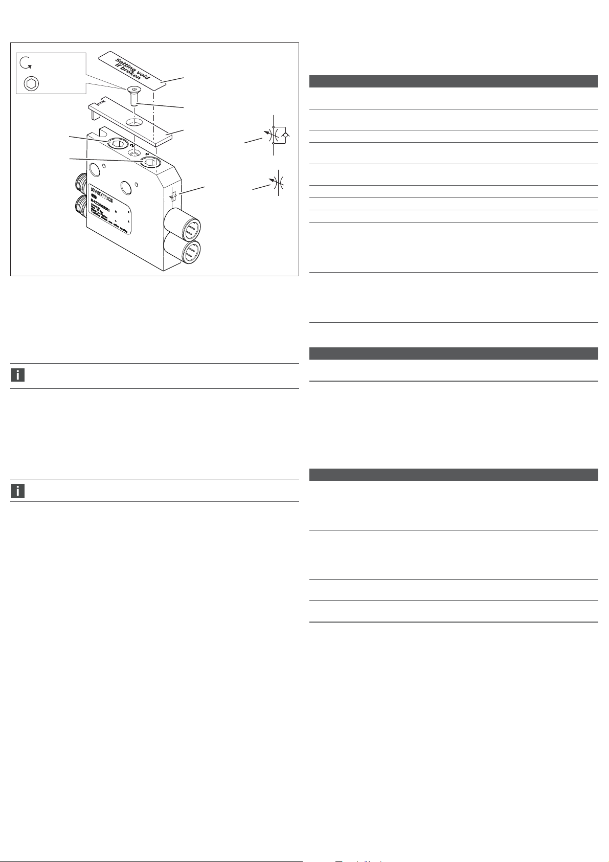
AVENTICS | R422003121–BAL–001–AC | Svenska 42
10 Tekniska data
= 1,2 Nm ±0,2
SW 2,5
21
22
fig 15: Strypmodul
21 Inställningsskruv för anslutning 2
22 Inställningsskruv för anslutning 4
23 Symbol för strypningstyp
24 Täckplatta som förhindrar att
inställningsskruvarna ändras.
Strypmodulen och anslutningarna ska varje månad kontrolleras, för att
garantera funktionen.
25 Skruvar för fastsättning av täckplatta
26 Täckande klistermärke
27 Symbol för envägsflödesriktning
28 Symbol för tvåvägsflödesriktning
26
25
24
23
27
28
Tabell 6: Allmänna data
Allmänna data
Temperaturområde vid
användning
Temperaturområde vid
förvaring
Arbetstryck min./max. 0–10 bar
Tryckregulatorns
reglerområde
Strypmodulens
inställningsområde
Tillåtet medium Tryckluft
Max. partikelstorlek 40 μm
Tryckluftens oljehalt 0–5 mg/m
Tryckdaggpunkten måste ligga minst 15 °C under omgivnings- och
mediumtemperaturen och får vara max. 3 °C.
Tryckluftens oljehalt måste vara konstant under hela livslängden.
O Använd enbart oljor som godkänts av AVENTICS, se online-katalog från
AVENTICS, kapitlet ''Teknisk information''.
Monteringsläge W Avluftningsmoduler, tryckregulatorer,
Tabell 7: Normer och riktlinjer
beaktade standarder och direktiv
DIN EN ISO 4414 Pneumatik – Allmänna regler för säkerhetskrav för system
och deras komponenter
-10 °C till 60 °C
–25 °C till 80 °C
0,5–10 bar
se bild 14 „Flödesdiagram för strypmodulen“
3
strypmoduler och pneumatiskt styrda
avstängningsmoduler:
valfri vid torr eller oljefri tryckluft
W maneullt styrd avstängningsmodul: se bild 1
8 Avfallshantering
O Följ nationella regler för avfallshantering.
9 Felsökning och åtgärder
Kontakta en kontaktadress som finns på http://www.aventics.com/contact.
Ytterligare tekniska data finns i online-katalogen på
www.aventics.com/pneumatics-catalog
11 Reservdelar och tillbehör
Tabell 8: Tillbehör
Beskrivning Materialnummer
Täckande klistermärke (4 styck):
förhindrar manipulering av strypmodulen.
Klistermärket kan klistras över inställningsskruvarna för
att förhindra obehörig åtkomst. När klistermärket har
klistras på kan det inte tas bort utan att det går sönder.
Täckplatta (inkl. skruvar och 4 täckande klistermärken):
förhindrar manipulering av strypmodulen.
Täckplattan kan monteras över inställningsskruvarna för
att förhindra obehörig åtkomst. Klistermärket kan klistras
på som ytterligare säkerhet.
Sammanfogningsset:
för sammanfogning av tvåkanaliga tryckregulatorer
Monteringsvinkelset:
för montering av funktionsmoduler på monteringsplattan.
Mer information om reservdelar och tillbehör finns i online-katalogen på
www.aventics.com/pneumatics-catalog.
R422003596
R422003595
R422103090
R422103091
Page 44

AVENTICS GmbH
Ulmer Straße 4
30880 Laatzen, GERMANY
Phone +49 (0) 5 11-21 36-0
Fax: +49 (0) 511-21 36-2 69
www.aventics.com
info@aventics.com
Further addresses:
www.aventics.com/contact
The data specified above only serve to
describe the product. No statements
concerning a certain condit ion or suitability
for a certain application can be derived
from our information. The given
information does not release the user from
the obligation of own judgement and
verification. It must be remembered that
our products are subject to a natural
process of wear and aging.
An example configuration is depicted on
the title page. The delivered product may
thus vary from that in the illustration.
Translation of the original operating
instructions. The original operating
instructions were created in the German
language.
R422003121–BAL–001–AC/2018-04
Subject to modifications. © All rights
reserved by AVENTICS GmbH, even and
especially in cases of proprietary rights
applications. It may not be reproduced or
given to third parties without its consent.
Loading...