

AVENTICS Instrucciones de servicio: Acoplador de bus para serie VS CL03/CL03-XL - PROFIBUS DP, Istruzioni per l’uso: Accoppiatore bus per serie VS CL03/CL03-XL - PROFIBUS DP, Bus coupler for series VS CL03/CL03-XL - PROFIBUS DP, Mode d’emploi: Coupleur de bus pour série VS CL03/CL03-XL - PROFIBUS DP, Betriebsanleitung: Buskoppler für Serie VS CL03/CL03-XL - PROFIBUS DP Manuals & Guides [sv]
...Page 1
Betriebsanleitung | Operating instructions | Mode d’emploi |
Istruzioni per l'uso | Instrucciones de servicio | Bruksanvisning
Buskoppler für Serie VS CL03/CL03-XL
Bus coupler for series VS CL03/CL03-XL
Coupleur de bus pour série VS CL03/CL03-XL
Accoppiatore bus per serie VS CL03/CL03-XL
Acoplador de bus para serie VS CL03/CL03-XL
Fältbussnod för serie VS CL03/CL03-XL
PROFIBUS DP
R402003657/06.2016, Replaces: 12.2015, DE/EN/FR/IT/ES/SV
DeutschEnglishFrançaisItalianoEspañolSvenska
Page 2

Page 3

AVENTICS | PROFIBUS DP | R402003657–BAL–001–AG 3
Inhalt
Inhalt
1 Zu dieser Dokumentation ............................................. 5
1.1 Gültigkeit der Dokumentation................................................5
1.2 Erforderliche und ergänzende Dokumentationen...........5
1.3 Darstellung von Informationen .............................................6
1.3.1 Sicherheitshinweise ............................................................... 6
1.3.2 Symbole ...................................................................................... 7
1.3.3 Abkürzungen ............................................................................. 7
2 Sicherheitshinweise ..................................................... 8
2.1 Zu diesem Kapitel......................................................................8
2.2 Bestimmungsgemäße Verwendung ....................................8
2.3 Nicht bestimmungsgemäße Verwendung .........................9
2.4 Qualifikation des Personals....................................................9
2.5 Allgemeine Sicherheitshinweise ....................................... 10
2.6 Produkt- und technologieabhängige
Sicherheitshinweise .............................................................. 11
3 Einsatzbereiche ........................................................... 12
4 Lieferumfang ............................................................... 13
5 Gerätebeschreibung ................................................... 14
5.1 Übersicht über den Buskoppler ......................................... 15
6 Montage ........................................................................ 17
6.1 CL03/CL03-XL mit PROFIBUS DP montieren................. 17
6.1.1 Abmessungen ........................................................................ 18
6.2 Buskoppler beschriften ........................................................18
6.3 Modul elektrisch anschließen............................................. 19
6.3.1 Allgemeine Hinweise zum Anschluss
des Buskopplers ................................................................... 20
6.3.2 Buskoppler als Zwischenstation anschließen ............. 22
6.3.3 Buskoppler als letzte Station anschließen ................... 22
6.3.4 Spannungsversorgung an den Buskoppler
anschließen ............................................................................ 22
6.3.5 FE-Anschluss ......................................................................... 24
Deutsch
Page 4

4 AVENTICS | PROFIBUS DP | R402003657–BAL–001–AG
Inhalt
7 Inbetriebnahme und Bedienung ................................ 25
7.1 Einstellungen vornehmen.................................................... 25
7.1.1 Datenrate einstellen ............................................................ 26
7.1.2 Dem Buskoppler eine Adresse zuweisen ...................... 26
7.1.3 Diagnosemeldungen einstellen ........................................ 27
7.1.4 Ventilversorgung auswählen ............................................ 28
7.2 Konfiguration des Bussystems .......................................... 31
7.2.1 GSD-Datei des Geräts laden .............................................. 32
7.2.2 PROFIBUS-Mastereinstellungen anpassen .................. 34
7.3 Test und Diagnose.................................................................. 37
7.3.1 Diagnose mit den LEDs des Buskopplers ..................... 37
7.3.2 Diagnose .................................................................................. 38
7.4 VS mit PROFIBUS DP in Betrieb nehmen........................ 39
8 Austausch .................................................................... 40
8.1 Buskoppler austauschen...................................................... 40
8.2 Multipolmodul durch einen Buskoppler ersetzen ........ 42
9 Pflege und Wartung .................................................... 44
9.1 Reinigen und pflegen............................................................. 44
9.2 Wartung..................................................................................... 45
9.3 Abfallentsorgung .................................................................... 45
10 Wenn Störungen auftreten ......................................... 45
11 Technische Daten ........................................................ 46
12 Ersatzteile und Zubehör ............................................. 47
13 Stichwortverzeichnis .................................................. 49
Page 5

AVENTICS | PROFIBUS DP | R402003657–BAL–001–AG 5
Zu dieser Dokumentation
1 Zu dieser Dokumentation
1.1 Gültigkeit der Dokumentation
Diese Dokumentation richtet sich an Elektro-/
Pneumatikfachkräfte.
Diese Dokumentation enthält wichtige Informationen, um das
Produkt sicher und sachgerecht zu montieren, in Betrieb zu
nehmen, zu bedienen, zu warten und einfache Störungen selbst
zu beseitigen.
O Lesen Sie diese Dokumentation vollständig und
insbesondere das Kapitel „Sicherheitshinweise“, bevor Sie
mit dem Produkt arbeiten.
1.2 Erforderliche und ergänzende
Dokumentationen
O Nehmen Sie das Produkt erst in Betrieb, wenn Ihnen
folgende Dokumentationen vorliegen und Sie diese
verstanden und beachtet haben.
Der Buskoppler ist eine Anlagenkomponente. Beachten Sie
auch die Anleitungen der übrigen Anlagenkomponenten.
Tabelle 1: Erforderliche und ergänzende Dokumentationen
Titel Dokumentnummer Dokumentart
Ventilsystem, Serie CL03/
CL03-XL, Clean Line
Anlagendokumentation
Weitere Angaben zu den CL03/CL03-XL-Komponenten der
VS-Serie entnehmen Sie dem Online-Katalog von AVENTICS
unter www.aventics.com/pneumatics-catalog.
R402000141 Anleitung
Deutsch
Page 6
6 AVENTICS | PROFIBUS DP | R402003657–BAL–001–AG
Zu dieser Dokumentation
1.3 Darstellung von Informationen
Damit Sie mit dieser Dokumentation schnell und sicher mit
Ihrem Produkt arbeiten können, werden einheitliche
Sicherheitshinweise, Symbole, Begriffe und Abkürzungen
verwendet. Zum besseren Verständnis sind diese in den
folgenden Abschnitten erklärt.
1.3.1 Sicherheitshinweise
In dieser Dokumentation stehen Sicherheitshinweise vor einer
Handlungsabfolge, bei der die Gefahr von Personen- oder
Sachschäden besteht. Die beschriebenen Maßnahmen zur
Gefahrenabwehr müssen eingehalten werden.
Sicherheitshinweise sind wie folgt aufgebaut:
SIGNALWORT
Art und Quelle der Gefahr
Folgen bei Nichtbeachtung
O Maßnahme zur Gefahrenabwehr
W Warnzeichen: macht auf die Gefahr aufmerksam
W Signalwort: gibt die Schwere der Gefahr an
W Art und Quelle der Gefahr: benennt die Art und Quelle der
Gefahr
W Folgen: beschreibt die Folgen bei Nichtbeachtung
W Abwehr: gibt an, wie man die Gefahr umgehen kann
Tabelle 2: Gefahrenklassen nach ANSI Z535.6-2006
Warnzeichen, Signalwort Bedeutung
Kennzeichnet eine gefährliche
GEFAHR
WARNUNG
Situation, in der Tod oder schwere
Körperverletzung eintreten werden,
wenn sie nicht vermieden wird
Kennzeichnet eine gefährliche
Situation, in der Tod oder schwere
Körperverletzung eintreten können,
wenn sie nicht vermieden wird
Page 7

AVENTICS | PROFIBUS DP | R402003657–BAL–001–AG 7
Zu dieser Dokumentation
Tabelle 2: Gefahrenklassen nach ANSI Z535.6-2006
Warnzeichen, Signalwort Bedeutung
Kennzeichnet eine gefährliche
Situation, in der leichte bis
VORSICHT
ACHTUNG
mittelschwere Körperverletzungen
eintreten können, wenn sie nicht
vermieden wird
Sachschäden: Das Produkt oder die
Umgebung können beschädigt
werden.
1.3.2 Symbole
Die folgenden Symbole kennzeichnen Hinweise, die nicht
sicherheitsrelevant sind, jedoch die Verständlichkeit der
Dokumentation erhöhen.
Tabelle 3: Bedeutung der Symbole
Symbol Bedeutung
Wenn diese Information nicht beachtet wird, kann das
Produkt nicht optimal genutzt bzw. betrieben werden.
O
1.
2.
3.
einzelner, unabhängiger Handlungsschritt
nummerierte Handlungsanweisung:
Die Ziffern geben an, dass die Handlungsschritte
aufeinander folgen.
1.3.3 Abkürzungen
In dieser Dokumentation werden folgende Abkürzungen
verwendet:
Tabelle 4: Abkürzungen
Abkürzung Bedeutung
FE Funktionserde (Funktionspotenzialausgleich)
GSD General Station Description Markup Language
VS Ventilsystem
Deutsch
Page 8

8 AVENTICS | PROFIBUS DP | R402003657–BAL–001–AG
Sicherheitshinweise
2 Sicherheitshinweise
2.1 Zu diesem Kapitel
Das Produkt wurde gemäß den allgemein anerkannten Regeln
der Technik hergestellt. Trotzdem besteht die Gefahr von
Personen- und Sachschäden, wenn Sie dieses Kapitel und die
Sicherheitshinweise in dieser Dokumentation nicht beachten.
O Lesen Sie diese Dokumentation gründlich und vollständig,
bevor Sie mit dem Produkt arbeiten.
O Bewahren Sie die Dokumentation so auf, dass sie jederzeit
für alle Benutzer zugänglich ist.
O Geben Sie das Produkt an Dritte stets zusammen mit den
erforderlichen Dokumentationen weiter.
2.2 Bestimmungsgemäße Verwendung
Bei dem Produkt handelt es sich um eine elektropneumatische
Anlagenkomponente.
Sie dürfen das Produkt wie folgt einsetzen:
W ausschließlich im industriellen Bereich
W ausschließlich in dem Leistungsbereich, der in den
technischen Daten angegeben ist.
W im industriellen Bereich (Klasse A).
Das Produkt ist für den professionellen Gebrauch und nicht für
die private Verwendung bestimmt.
Die bestimmungsgemäße Verwendung schließt auch ein, dass
Sie diese Dokumentation und insbesondere das Kapitel
„Sicherheitshinweise“ vollständig gelesen und verstanden
haben.
Page 9

AVENTICS | PROFIBUS DP | R402003657–BAL–001–AG 9
Sicherheitshinweise
2.3 Nicht bestimmungsgemäße Verwendung
Jeder andere Gebrauch als in der bestimmungsgemäßen
Verwendung beschrieben ist nicht bestimmungsgemäß und
deshalb unzulässig.
Wenn ungeeignete Produkte in sicherheitsrelevanten
Anwendungen eingebaut oder verwendet werden, können
unbeabsichtigte Betriebszustände in der Anwendung auftreten,
die Personen- und/oder Sachschäden verursachen können.
Setzen Sie daher ein Produkt nur dann in sicherheitsrelevanten
Anwendungen ein, wenn diese Verwendung ausdrücklich in der
Dokumentation des Produkts spezifiziert und erlaubt ist.
Beispielsweise in Ex-Schutz Bereichen oder in
sicherheitsbezogenen Teilen einer Steuerung (funktionale
Sicherheit).
Für Schäden bei nicht bestimmungsgemäßer Verwendung
übernimmt die AVENTICS GmbH keine Haftung. Die Risiken bei
nicht bestimmungsgemäßer Verwendung liegen allein beim
Benutzer.
Zur nicht bestimmungsgemäßen Verwendung des Produkts
gehört:
W die Veränderung bzw. der Umbau des Produkts,
W die Verwendung außerhalb der Anwendungsgebiete, die in
dieser Anleitung genannt werden,
W die Verwendung unter Betriebsbedingungen, die von den in
dieser Anleitung beschriebenen abweichen.
Deutsch
2.4 Qualifikation des Personals
Die in dieser Dokumentation beschriebenen Tätigkeiten
erfordern grundlegende Kenntnisse der Elektrik und Pneumatik
sowie Kenntnisse der zugehörigen Fachbegriffe. Um die sichere
Verwendung zu gewährleisten, dürfen diese Tätigkeiten daher
nur von einer entsprechenden Fachkraft oder einer
unterwiesenen Person unter Leitung einer Fachkraft
durchgeführt werden.
Page 10

10 AVENTICS | PROFIBUS DP | R402003657–BAL–001–AG
Sicherheitshinweise
Eine Fachkraft ist, wer aufgrund seiner fachlichen Ausbildung,
seiner Kenntnisse und Erfahrungen sowie seiner Kenntnisse
der einschlägigen Bestimmungen die ihm übertragenen
Arbeiten beurteilen, mögliche Gefahren erkennen und
geeignete Sicherheitsmaßnahmen treffen kann. Eine Fachkraft
muss die einschlägigen fachspezifischen Regeln einhalten.
2.5 Allgemeine Sicherheitshinweise
W Beachten Sie die gültigen Vorschriften zur Unfallverhütung
und zum Umweltschutz.
W Beachten Sie die Sicherheitsvorschriften und -
bestimmungen des Landes, in dem das Produkt eingesetzt/
angewendet wird.
W Verwenden Sie AVENTICS-Produkte nur in technisch
einwandfreiem Zustand.
W Beachten Sie alle Hinweise auf dem Produkt.
W Personen, die AVENTICS-Produkte montieren, bedienen,
demontieren oder warten dürfen nicht unter dem Einfluss
von Alkohol, sonstigen Drogen oder Medikamenten, die die
Reaktionsfähigkeit beeinflussen, stehen.
W Verwenden Sie nur vom Hersteller zugelassene Zubehör-
und Ersatzteile, um Personengefährdungen wegen nicht
geeigneter Ersatzteile auszuschließen.
W Halten Sie die in der Produktdokumentation angegebenen
technischen Daten und Umgebungsbedingungen ein.
W Wenn in sicherheitsrelevanten Anwendungen ungeeignete
Produkte eingebaut oder verwendet werden, können
unbeabsichtigte Betriebszustände in der Anwendung
auftreten, die Personen- und/oder Sachschäden
verursachen können. Setzen Sie daher ein Produkt nur dann
in sicherheitsrelevante Anwendungen ein, wenn diese
Verwendung ausdrücklich in der Dokumentation des
Produkts spezifiziert und erlaubt ist.
W Sie dürfen das Produkt erst dann in Betrieb nehmen, wenn
festgestellt wurde, dass das Endprodukt (beispielsweise
eine Maschine oder Anlage), in das die AVENTICS-Produkte
Page 11

AVENTICS | PROFIBUS DP | R402003657–BAL–001–AG 11
Sicherheitshinweise
eingebaut sind, den länderspezifischen Bestimmungen,
Sicherheitsvorschriften und Normen der Anwendung
entspricht.
2.6 Produkt- und technologieabhängige
Sicherheitshinweise
W Belasten Sie das Gerät unter keinen Umständen
mechanisch.
W Stellen Sie keine Gegenstände darauf ab.
W Stellen Sie sicher, dass die Spannungsversorgung
innerhalb der angegebenen Toleranz der Module liegt.
W Beachten Sie die Sicherheitshinweise der
Betriebsanleitung Ihres Ventilsystems.
W Verwenden Sie für die Komponente ausschließlich die
folgende Spannungsversorgung:
– 24-V-DC PELV-Stromkreise nach DIN EN 60204-1/
IEC 60204-1.
– Die Stromquelle für PELV muss ein
Sicherheitstrenntransformator nach IEC 61558-1 oder
IEC 61558-2-6 sein oder eine Stromquelle, die den
gleichen Sicherheitsgrad erfüllt wie ein
Sicherheitstrenntransformator.
– Stellen Sie sicher, dass die Spannungsversorgung des
Netzteils immer kleiner als 300 V AC (Außenleiter –
Neutralleiter) ist.
W Schalten Sie die Betriebsspannung aus, bevor Sie Stecker
verbinden oder trennen.
Bei der Montage W Die Gewährleistung gilt ausschließlich für die ausgelieferte
Konfiguration. Die Gewährleistung erlischt bei fehlerhafter
Montage.
W Schalten Sie immer den betreffenden Anlagenteil
spannungs- und drucklos, bevor Sie das Gerät montieren
oder demontieren. Sorgen Sie dafür, dass die Anlage
während der Montagearbeiten gegen Wiederanschalten
gesichert ist.
Deutsch
Page 12

12 AVENTICS | PROFIBUS DP | R402003657–BAL–001–AG
Einsatzbereiche
W Verbinden Sie die Module und das Ventilsystem mit der
Funktionserde (FE):
– Anschluss nach DIN EN 60204-1/IEC 60204-1
Bei der Inbetriebnahme W Die Installation darf nur in spannungsfreiem und
drucklosem Zustand und nur durch geschultes
Fachpersonal erfolgen. Führen Sie die elektrische
Inbetriebnahme nur in drucklosem Zustand durch, um
gefährliche Bewegungen der Aktoren zu vermeiden.
W Nehmen Sie das System nur in Betrieb, wenn es komplett
montiert, korrekt verdrahtet und konfiguriert ist, und
nachdem Sie es getestet haben.
W Das Gerät unterliegt der Schutzklasse IP69K. Stellen Sie vor
der Inbetriebnahme sicher, dass alle Dichtungen und
Verschlüsse der Steckverbindungen dicht sind, um zu
verhindern, dass Flüssigkeiten und Fremdkörper in das
Gerät eindringen können.
Während des Betriebs W Sorgen Sie für genügend Luftaustausch bzw. für
ausreichend Kühlung, wenn Ihr Ventilsystem Folgendes
aufweist:
– volle Bestückung
– Dauerbelastung der Magnetspulen
Bei der Reinigung W Verwenden Sie Lösemittel oder Reinigungsmittel nur in
geringer Konzentration und lassen Sie diese nicht längere
Zeit einwirken.
W Verstoßen Sie nicht gegen die Bedingungen für IP69K.
Abfallentsorgung W Entsorgen Sie das Gerät nach den Bestimmungen Ihres
Landes.
3 Einsatzbereiche
Der Buskoppler dient zur elektrischen Ansteuerung der Ventile
des Ventilsystems CL03/CL03-XL über das PROFIBUSFeldbussystem. Es wird zur Steuerung von bis zu 16 Ventilen
direkt auf das CL03/CL03-XL Ventilsystem montiert.
Der Buskoppler ist ausschließlich für den Betrieb als Slave an
einem PROFIBUS Bussystem nach EN 50170 Teil 2 bestimmt.
Page 13

AVENTICS | PROFIBUS DP | R402003657–BAL–001–AG 13
Lieferumfang
4 Lieferumfang
Im Lieferumfang sind enthalten:
W CL03/CL03-XL Ventilsystem mit PROFIBUS gemäß
Konfiguration und Bestellung
W Montageanleitung zum Ventilsystem
W Weitere Anleitungen gemäß Konfiguration
W CD R412023902
Das Ventilsystem wird individuell mit Hilfe des OnlineKonfigurators von AVENTICS (www.aventics.com)
konfiguriert. Während der Konfiguration wird eine
individuelle Bestellnummer generiert. Diese Nummer
stimmt genau mit der ausgelieferten Konfiguration überein.
Deutsch
Page 14

14 AVENTICS | PROFIBUS DP | R402003657–BAL–001–AG
Gerätebeschreibung
5 Gerätebeschreibung
Durch den Buskoppler ist es möglich, das CL03/CL03-XL
Ventilsystem über eine PROFIBUS-Feldbusverbindung
anzusteuern. Neben dem Anschluss von Datenleitungen und
Spannungsversorgungen ermöglicht der Buskoppler die
Einstellung verschiedener Busparameter sowie die Diagnose
über LEDs und das PROFIBUS-Protokoll. Eine ausführlichere
Beschreibung des Buskopplers finden Sie auf den folgenden
Seiten.
1
Abb. 1: Übersicht zum VS CL03/CL03-XL mit Buskoppler (Beispielkonfiguration)
1 PROFIBUS-Ventiltreiber mit darunter
befindlichen pneumatischen und elektrischen
Anschlüssen
2 1 bis 16 Anschlussplatten für CL03-Ventile /
1 bis 18 Anschlussplatten für CL03-XL-Ventile
3 Endplatte für pneumatische Anschlüsse
3
2
Page 15

AVENTICS | PROFIBUS DP | R402003657–BAL–001–AG 15
Gerätebeschreibung
5.1 Übersicht über den Buskoppler
1
2
¨
45
3
POW
X1
BUS IN
X71
BUS OUT
X72
6
7
8
ER
0
Abb. 2: Übersicht über den Buskoppler
1 Busadressenfeld
2 LED-Anzeige für Diagnosemeldungen
3 Anschluss BUS OUT X72 für den Buskoppler zur
Ansteuerung weiterer PROFIBUS-Teilnehmer
4 Anschluss BUS IN X71 für den Buskoppler zur Ansteuerung
der CL03/CL03-XL-Ventile
5 Anschluss POWER X10 zur Spannungsversorgung der
Ventilspulen
6 Schiebeschalter S4 für Auswahl der Ventilversorgung
7 Drehschalter S1, S2 für Zuweisung der PROFIBUS-Adresse
8 DIP-Schalter S3 für Moduseinstellung
Der Buskoppler ist ausschließlich für den Betrieb als Slave in
einem PROFIBUS-Link nach EN 50170 Teil 2 bestimmt.
Deutsch
Page 16

16 AVENTICS | PROFIBUS DP | R402003657–BAL–001–AG
Gerätebeschreibung
Als Feldbuskabel wird ein verdrilltes, geschirmtes Adernpaar
benutzt. Die Buskabellänge kann je nach
Übertragungsgeschwindigkeit (ohne Repeater) bis zu 1,2 km
betragen. Ohne Repeater sind 32 Teilnehmer je Segment
anschließbar. Mit Repeatern ist eine Erweiterung auf bis zu
127 Teilnehmer möglich.
PROFIBUS-Adresse Die Adresse des Buskopplers wird über die beiden Drehschalter
S1 und S2 eingestellt.
Datenrate Der Buskoppler stellt sich automatisch auf die
Masterbusgeschwindigkeit (zwischen 9,6 kbps und 12 Mbps)
ein.
Diagnose Die Versorgungsspannungen für den elektronischen
Schaltkreis und die Ventilansteuerung werden überwacht.
Wenn die eingestellte Schwelle unter- oder überschritten wird,
wird ein Fehlersignal erzeugt und mittels Diagnose-LEDs auf
dem Buskoppler und Diagnosenachrichten gemeldet.
Anzahl der
angesteuerten Ventile
Es können in jeder passenden Kombination aus beidseitig und
einseitig betätigten Ventilen bis zu 32 Spulen angesteuert
werden.
Page 17

AVENTICS | PROFIBUS DP | R402003657–BAL–001–AG 17
Montage
6 Montage
6.1 CL03/CL03-XL mit PROFIBUS DP montieren
ACHTUNG
Gefahr von Schäden an der Ventileinheit
Der Buskoppler kann beschädigt werden, wenn die
Abdeckung mechanischen Kräften, z. B. einem harten Stoß,
ausgesetzt wird.
O Stellen Sie sicher, dass das Gerät gegen Stöße geschützt
ist.
O Stellen Sie sicher, dass das Gerät beim Transport gut
verpackt ist.
Sie erhalten Ihr individuell konfiguriertes Ventilsystem der
Serie CL03/CL03-XL komplett verschraubt mit allen
Komponenten:
W Buskoppler
W Ventilsystem
W Endplatte
Deutsch
Die Montage des gesamten Ventilsystems ist in der
beiliegenden Betriebsanleitung für das VS CL03/CL03-XL
ausführlich beschrieben. Das VS kann in jeder beliebigen Lage
eingebaut werden. Es sollte jedoch möglichst vermieden
werden, das VS mit den Anschlüssen nach oben einzubauen.
Vermeiden Sie auch, dass sich die Vorsteuerventile beim Einbau
des VS am unteren Ende befinden.
Die Abmessungen des kompletten VS variieren je nach
Konfiguration. Siehe Abb. 3. Dabei ist ‘N’ = Anzahl der
Anschlussplatten.
Page 18

18 AVENTICS | PROFIBUS DP | R402003657–BAL–001–AG
Montage
6.1.1 Abmessungen
42.25
56.9 + N x A
127.25 + N x A
A
85.0
149
169
15.1 + N x A
54.54
11.7
42
B
Abb. 3: Abmessungen CL03/CL03-XL VS mit PROFIBUS
CL03: A = 30,0 mm
B = 78,5 mm
CL03-XL: A = 36,0 mm
B = 89,15 mm
6.2 Buskoppler beschriften
PROFIBUS-Adresse O Schreiben Sie die Adresse des Buskopplers in das Feld
„ADDRESS” auf der Abdeckung des Moduls. Informationen
zur Einstellung der Adresse finden Sie im Abschnitt „Dem
Buskoppler eine Adresse zuweisen” auf Seite 26.
Page 19

AVENTICS | PROFIBUS DP | R402003657–BAL–001–AG 19
Montage
6.3 Modul elektrisch anschließen
WARNUNG
Anliegende elektrische Spannung
Verletzungsgefahr durch elektrischen Schlag.
O Schalten Sie immer den betreffenden Anlagenteil
spannungsfrei und drucklos, bevor Sie am Ventilsystem
Module elektrisch anschließen.
O Stecken oder ziehen Sie keine Steckverbinder unter Last.
ACHTUNG
Stromfluss im Schirm auf Grund von
Potenzialunterschieden
Über den Schirm des PROFIBUS-Kabels dürfen keine durch
Potenzialunterschiede bedingten Ausgleichsströme fließen,
da dadurch die Schirmung aufgehoben wird und die Leitung
sowie die angeschlossenen Teilnehmer beschädigt werden
können.
O Verbinden Sie gegebenenfalls die Massepunkte der
Anlage über eine separate Leitung.
Deutsch
Page 20
20 AVENTICS | PROFIBUS DP | R402003657–BAL–001–AG
Montage
6.3.1 Allgemeine Hinweise zum Anschluss des
Buskopplers
Wenn möglich, benutzen Sie für das Anschließen der
Module konfektionierte Steckverbindungen und Kabel.
Beachten Sie hierzu „Ersatzteile und Zubehör” auf Seite 47.
O Wenn Sie keine konfektionierten Steckverbindungen und
Kabel verwenden, verbinden Sie die Kabeladern mit den
Bussteckern (X71, X72) gemäß der Pin-Belegung in Tab.
und beachten Sie dabei die nachfolgenden Anweisungen.
BUS IN
X71
41
5
3
2
2413
5
BUS OUT
X72
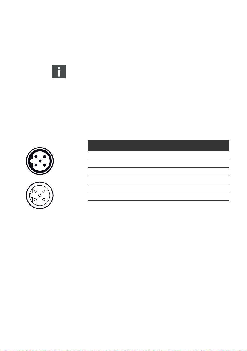
Tabelle 5: Belegung X71 (BUS IN) und X72 (BUS OUT), M12, B-codiert
Pin Signal Bedeutung
1 VP Versorgungsspannung + (P5V)
2 RxD/TxD-N
2)
Empfangs-/Sendedaten-N, Datenleitung A (grün)
3 DGND Bezugspotenzial zu VP, 0V
4 RxD/TxD-P2)Empfangs-/Sendedaten-P, Datenleitung B (rot)
5 Schirm Schirm bzw. Funktionserde
Gehäuse Schirm bzw. Funktionserde
1)
Ausgangsspannung des Buskopplers für externe Buskomponenten (max. 25 mA).
2)
Die Zuordnung der grünen und roten Ader ist nicht standardisiert. AVENTICS
empfiehlt die in der Tabelle angegebene Zuordnung.
1)
1)
Page 21

Feldbuskabel
AVENTICS | PROFIBUS DP | R402003657–BAL–001–AG 21
Montage
ACHTUNG
Gefahr durch falsch konfektionierte oder beschädigte
Kabel!
Der Buskoppler kann beschädigt werden.
O Verwenden Sie ausschließlich geschirmte und geprüfte
Kabel.
Falsche Verkabelung!
Eine falsche oder fehlerhafte Verkabelung führt zu
Fehlfunktionen und zur Beschädigung des Netzwerks.
O Halten Sie – sofern nicht anders erwähnt – die
PROFIBUS-Spezifikationen ein.
O Verwenden Sie nur Kabel, die den Spezifikationen des
Feldbusses sowie den Anforderungen bzgl.
Geschwindigkeit und Länge der Verbindung entsprechen.
O Montieren Sie Kabel und Stecker fachgerecht
entsprechend der Montageanweisung, damit Schutzart
und Zugentlastung gewährleistet sind.
O Schließen Sie niemals die beiden Feldbusanschlüsse X71
und X72 am gleichen Switch/Hub an.
Deutsch
O Schließen Sie den Schirm an beiden Seiten des Buskabels
direkt an das Steckergehäuse (EMV-Gehäuse) an. So
schützen Sie die Datenleitungen gegen
Störungseinkopplungen.
Bei Verwendung eines Kabels mit Beilauflitze kann diese
zusätzlich an Pin 5 der Busstecker (X71, X72)
angeschlossen werden.
Anschlusstechnik und Steckerbelegung entsprechen den
Vorgaben der technischen Richtlinie 'Interconnection
Technology' (PNO-Best.-Nr. 2142).
Page 22
22 AVENTICS | PROFIBUS DP | R402003657–BAL–001–AG
Montage
6.3.2 Buskoppler als Zwischenstation anschließen
1. Wenn Sie keine konfektionierten Steckverbindungen und
Kabel verwenden, beachten Sie die Hinweise auf der vorigen
Seite.
2. Schließen Sie das ankommende Buskabel am Eingang
POWER
X10
BUS IN
X71
BUS OUT
X72
1
2
X71 (1) an.
3. Verbinden Sie die abgehende Busleitung über den Ausgang
X72 (2) mit dem nächsten Modul.
4. Stellen Sie sicher, dass alle Stecker fest mit dem Gehäuse
des Buskopplers verbunden sind.
6.3.3 Buskoppler als letzte Station anschließen
1. Wenn Sie keine konfektionierten Steckverbindungen und
Kabel verwenden, beachten Sie die Hinweise auf der vorigen
Seite.
2. Schließen Sie das ankommende Buskabel am Eingang
X71 (1) an.
3. Versehen Sie die Gerätedose X72 (BUS OUT) (2) mit einem
PROFIBUS-Abschlussstecker (siehe „Ersatzteile und
Zubehör” auf Seite 47).
4. Stellen Sie sicher, dass alle Stecker fest mit dem Gehäuse
des Buskopplers verbunden sind.
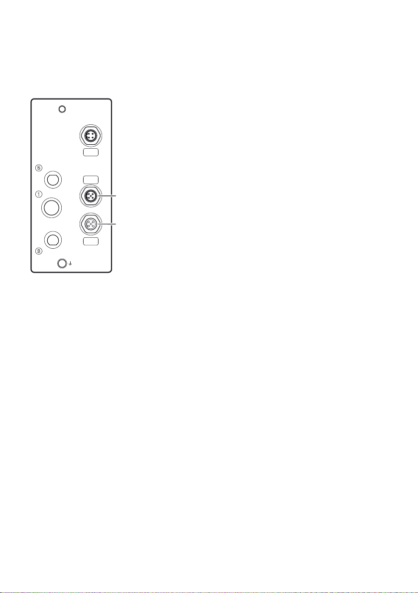
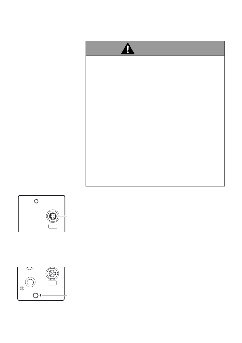
6.3.4 Spannungsversorgung an den Buskoppler
anschließen
Die POWER-Buchse (X10) dient zur Spannungsversorgung der
internen Elektronik des Buskopplers und zur Versorgung der
Ventile mit zwei verschiedenen externen Spannungsquellen
(24 V).
Die Pin-Belegung entspricht den Angaben in Tabelle 6.
Informationen zu konfektionierten Kabel finden Sie in Abschnitt
„Ersatzteile und Zubehör” auf Seite 47.
Page 23

2413
POWER
X10
AVENTICS | PROFIBUS DP | R402003657–BAL–001–AG 23
Montage
Tabelle 6: Belegung des Gerätesteckers X10 (POWER), M12, A-codiert
Pin X10 Belegung
1ULSpannungsversorgung Buskoppler-Elektronik
2UQ1 erste Spannungsversorgung Ventile
3 0V Masse für U
4UQ2 zweite Spannungsversorgung Ventile
UQ1 und UQ2
L
,
W UL, UQ1 und UQ2 sind galvanisch miteinander verbunden.
W Über die Ventilversorgung U
Q1 und UQ2 können die Ventile
byteweise (entspricht je 4 beidseitig betätigten Ventilen oder
8 einseitig betätigten Ventilen) abgeschaltet werden.
W Die Zuordnung der Ventilgruppen (4 oder 8 Ventile) erfolgt
über den Schiebeschalter S4 (siehe „Ventilversorgung
auswählen” auf Seite 28). Dadurch ist z. B. eine separate
Abschaltung möglich.
W Beide Ventilversorgungsspannungen (X10 Pin2, Pin4)
müssen mit einer externen Sicherung (3A, F) abgesichert
werden.
Das Kabel für die Spannungsversorgung muss folgende
Anforderungen erfüllen:
W Kabelbuchse: 4-polig, A-codiert ohne Mittelloch
W Leitungsquerschnitt: ≥0,5 mm
2
pro Ader (an Gesamtstrom
und Leitungslänge angepasst)
W Länge: max. 20 m
Tabelle 7: Stromaufnahme an X10 (POWER) am Buskoppler
Signal Belegung Gesamtstrom
U
L
UQ1 Ventile Max. 3 A
UQ2 Ventile Max. 3 A
Elektronischer Schaltkreis, Eingang Max. 0,5 A
Deutsch
Page 24
24 AVENTICS | PROFIBUS DP | R402003657–BAL–001–AG
Montage
WARNUNG
Stromschlag durch falsches Netzteil
Ein Netzteil mit nicht sicherer Trennung kann im Fehlerfall zu
gefährlichen Spannungen führen. Dies kann zu Verletzungen
durch elektrischen Schlag oder zur Schädigung des Systems
führen.
O Verwenden Sie für die Komponente ausschließlich die
folgende Spannungsversorgung:
24-V-DC PELV-Stromkreise nach DIN EN 60204-1/
IEC 60204-1.
Die Stromquelle für PELV muss ein
Sicherheitstrenntransformator nach IEC 61558-1 oder
IEC 61558-2-6 sein oder eine Stromquelle, die den
gleichen Sicherheitsgrad erfüllt wie ein
Sicherheitstrenntransformator.
Stellen Sie sicher, dass die Spannungsversorgung des
Netzteils immer kleiner als 300 V AC (Außenleiter –
Neutralleiter) ist.
3
POWER
X10
BUS OUT
X72
4
Erdung bei
VS CL03/CL03-XL
So schließen Sie die Spannungsversorgung des Buskopplers
an:
1. Wenn Sie kein konfektioniertes Kabel verwenden, müssen
Sie sicherstellen, dass das Kabel für die
Spannungsversorgung über die korrekte Pin-Belegung
verfügt (siehe Tabelle 6 auf Seite 23).
2. Schließen Sie die Spannungsversorgung an den Anschluss
POWER X10 (3) am Buskoppler an.
3. Kontrollieren Sie die Spezifikationen der
Betriebsspannungen gemäß den elektrischen Kenngrößen
und halten Sie diese ein (siehe Kapitel „Technische Daten“
auf Seite 46).
6.3.5 FE-Anschluss
O Verbinden Sie zur Ableitung von EMV-Störungen den FE-
Anschluss (4) am Buskoppler über eine niederimpedante
Leitung mit der Erde. Empfohlener Kabelquerschnitt: 10 mm
2
Page 25

AVENTICS | PROFIBUS DP | R402003657–BAL–001–AG 25
Inbetriebnahme und Bedienung
7 Inbetriebnahme und Bedienung
7.1 Einstellungen vornehmen
Folgende Einstellungen müssen Sie durchführen:
W Datenrate einstellen
W Dem Buskoppler eine Adresse zuweisen
W Diagnosemeldungen einstellen
W Ventilversorgung auswählen
Alle diese Einstellungen erfolgen mit den Schaltern unter der
Abdeckung des Buskopplers. Die Schalterstellungen können Sie
der Abb. 4 unten entnehmen.
Gehen Sie wie folgt vor, um die Einstellungen vorzunehmen.
1. Entfernen Sie die Abdeckung des Buskopplers, indem Sie
die vier Schrauben (1) lösen.
2. Nehmen Sie die Einstellung der Schalter wie unten
beschrieben vor.
3. Schrauben Sie die Abdeckung vorsichtig wieder fest wie in
Abb. 4 unten gezeigt. Stellen Sie den korrekten Sitz der
Dichtung (2) sicher. Ziehen Sie die Schrauben (1) mit einem
Drehmoment von 1,0 bis 1,2 Nm fest.
Deutsch
Page 26

26 AVENTICS | PROFIBUS DP | R402003657–BAL–001–AG
Inbetriebnahme und Bedienung
S4
1
2
S1 S2
S2
S1
Abb. 4: Entfernen/Verschrauben der Abdeckung des Buskopplers
S3
7.1.1 Datenrate einstellen
Der Buskoppler stellt sich automatisch auf die vom Busmaster
vorgegebene Datenrate (Baudrate) ein.
O Beachten Sie die zulässigen Datenraten:
– 9,6 / 19,2 / 93,75 / 187,5 / 500 / 1.500 kbps
– 3 / 6 / 12 Mbps
7.1.2 Dem Buskoppler eine Adresse zuweisen
Der Buskoppler wird vom Werk aus mit einer Stationsadresse
von „66” geliefert.
Damit jeder einzelne Buskoppler innerhalb eines PROFIBUSSegments korrekt identifiziert werden kann, muss für jedes
Modul eine eindeutige Adresse eingestellt werden.
O Vergeben Sie mit Schalter S1 und S2 nach Belieben
Stationsadressen von 2 bis 99:
– S1: Einerstelle von 0 bis 9
– S2: Zehnerstelle von 0 bis 9
– [S2] [S1] = Stationsadresse
Page 27

AVENTICS | PROFIBUS DP | R402003657–BAL–001–AG 27
Inbetriebnahme und Bedienung
Die Vergabe derselben Adresse an zwei Buskoppler
innerhalb desselben PROFIBUS-Segments ist nicht
zulässig.
Wenn der Buskoppler beim Einschalten den ungültigen Wert „0“
feststellt, wird die Stationsadresse automatisch solange auf
„126“ gesetzt, bis der Benutzer sie in den erforderlichen Wert
ändert.
VORSICHT
Änderungen im laufenden Betrieb
Adressänderungen werden erst nach einem Neustart
wirksam.
O Ändern Sie die Einstellungen niemals im laufenden
Betrieb.
O Schalten Sie das Gerät aus, bevor die Adresseinstellung
ändern.
7.1.3 Diagnosemeldungen einstellen
ON
OFF
Zur Wahl der gewünschten Diagnosemeldungen wird der DIPSchalter S3 verwendet.
Bei der Auslieferung befinden sich alle Schalter in Stellung
OFF. Dies bedeutet, dass keine Diagnosemeldungen an den
Busmaster gesendet werden.
Der Schalter S3.6 ist nicht belegt.
S3
↑
↓
O Stellen Sie die benötigten Diagnosemeldungen mit dem
Schalter S3 ein (siehe 8).
Nach einem Neustart werden die Änderungen wirksam.
Deutsch
Page 28

28 AVENTICS | PROFIBUS DP | R402003657–BAL–001–AG
Inbetriebnahme und Bedienung
Tabelle 8: DIP-Schalter S3 für Wahl von Diagnosemeldungen, die an den Master gesendet werden
Bit Diagnose Hinweis
S3.1 OFF: Überlastmeldung Ventilsteuerung OFF Diagnosemeldung, wenn ein Ventil Überlast
ON: Überlastmeldung Ventilsteuerung ON
S3.2 OFF: 12.5 V < UQ1 < 21,6 V/20,4 V
Meldung Spannung zu gering OFF
ON: 12.5 V < UQ1 < 21,6 V/20,4 V
Meldung Spannung zu gering ON
S3.3 OFF: 12.5 V < UQ2 < 21,6 V/20,4 V
Meldung Spannung zu gering OFF
ON: 12.5 V < UQ2 < 21,6 V/20,4 V
Meldung Spannung zu gering ON
S3.4 OFF: UQ1 < 12,5 V Meldung OFF
ON: UQ1 < 12,5 V Meldung ON
S3.5 OFF: UQ2 < 12,5 V Meldung OFF
ON: UQ2 < 12,5 V Meldung ON
S3.6 NC
S3.7 OFF: Schwelle für UQ1 ist 20,4 V Für unterschiedliche Ventilserien kann die
ON: Schwelle für UQ1 ist 21,6 V
S3.8 OFF: Schwelle für UQ2 ist 20,4 V
ON: Schwelle für UQ2 ist 21,6 V
bzw. Kurzschluss aufweist. Die
Diagnosemeldung ist nur vorhanden,
solange dieses Ventil angesteuert ist.
Um ein sicheres Schalten der Ventile zu
gewährleisten, muss die Schaltspannung
20,4 V bzw. 21,6 V betragen! Unterspannung
bei den Ventilen liegt vor, wenn die
Spannung UQ zwischen 12,5 V und 20,4 V/
21,6 V liegt. Die Unterspannungsmeldung
erscheint beim Einschalten nach ca. 10 ms
und beim Ausschalten nach ca. 20 ms. Tritt
eine Spannung kleiner als 12,5 V auf, wird
dieses gesondert gemeldet.
Schwelle 20,4 V/21,6 V angepasst werden.
Pos. 2 ↑
Pos. 1 ↓
S4
7.1.4 Ventilversorgung auswählen
Mit dem Schiebeschalter S4 kann die
Ventilspannungsversorgung blockweise ausgewählt werden.
Es kann zwischen Ventilversorgung aus dem PROFIBUS-Strang
und den Spannungen U
umgeschaltet werden.
Alle Schalter befinden sich bei Auslieferung in der
Stellung 1.
und UQ2 aus der externen Versorgung
Q1
Page 29

AVENTICS | PROFIBUS DP | R402003657–BAL–001–AG 29
Inbetriebnahme und Bedienung
ACHTUNG
Spannung an Schalter
Der Schalter kann beschädigt werden, wenn beim Schalten
Spannung an den Pins anliegt.
O Betätigen Sie den Schalter nur in spannungslosem
Zustand!
So ordnen Sie die Ventilversorgung zu:
O Ordnen Sie mit Hilfe des Schalters S4 jeder Ventilgruppe
eine der beiden Versorgungsspannungen U
(siehe Tabelle 9).
Tabelle 9: Zuordnung der Schalter S4
Schieber Funktion Stellung 1 (nach unten) Stellung 2 (nach oben)
S4.1 Spannungsversorgung
Ansteuerbyte 1
S4.2 Spannungsversorgung
Ansteuerbyte 2
S4.3 Spannungsversorgung
Ansteuerbyte 3
S4.4 Spannungsversorgung
Ansteuerbyte 4
UQ1 (externe Versorgung,
Pin 2, weiß)
UQ1 (externe Versorgung,
Pin 2, weiß)
UQ1 (externe Versorgung,
Pin 2, weiß)
UQ1 (externe Versorgung,
Pin 2, weiß)
UQ2 (externe Versorgung,
UQ2 (externe Versorgung,
UQ2 (externe Versorgung,
UQ2 (externe Versorgung,
Q1 oder UQ2 zu
Pin 4, schwarz)
Pin 4, schwarz)
Pin 4, schwarz)
Pin 4, schwarz)
Deutsch
Für die Zuordnung des Schalters S4 und der Versorgung
montierter Ventile finden Sie die folgenden
Beispielkombinationen für 32 Ventilspulen in Tabelle 10.
Beispiele
Beispiel 1 Anschlussplatten für beidseitig betätigte Ventile beidseitig betätigte Ventile
Beispiel 2 Anschlussplatten für beidseitig betätigte Ventile einseitig betätigte Ventile
Beispiel 3 Anschlussplatten für beidseitig betätigte Ventile ein- und beidseitig betätigte Ventile
1)
1)
Verwendete Anschlussplatten Ventilbestückung
Entsprechend Ihren Anforderungen können Sie auch andere Kombinationen wählen.
Page 30
30 AVENTICS | PROFIBUS DP | R402003657–BAL–001–AG
Inbetriebnahme und Bedienung
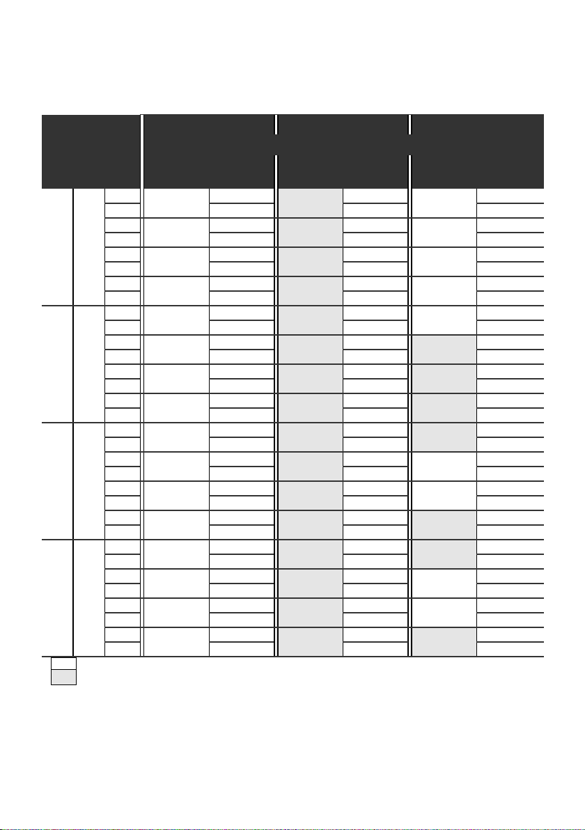
Tabelle 10: Beispiele für die Zuordnung von Schaltern und Ventilversorgung, 32 Ventilspulen
Beispiel 1 Beispiel 2 Beispiel 3
Anschlussplatte für beidseitig betätigte Ventile
Schalter
Byte
Adresse
Ventilplatz
1)
Spule LED
S4.1 0 A0.0 1 14 114114
A0.1 12 – 12
A0.2 2 14 214214
A0.3 12 – 12
A0.4 3 14 314314
A0.5 12 – 12
A0.6 4 14 414414
A0.7 12 – 12
S4.2 1 A1.0 5 14 514514
A1.1 12 – 12
A1.2 6 14 614614
A1.3 12 – –
A1.4 7 14 714714
A1.5 12 – –
A1.6 8 14 814814
A1.7 12 – –
S4.3 2 A2.0 9 14 914914
A2.1 12 –
A2.2 10 14 10 14 10 14
A2.3 12 – 12
A2.4 11 14 11 14 11 14
A2.5 12 – 12
A2.6 12 14 12 14 12 14
A2.7 12 – –
S4.4 3 A3.0 13 14 13 14 13 14
A3.1 12 – –
A3.2 14 14 14 14 14 14
A3.3 12 – 12
A3.4 15 14 15 14 15 14
A3.5 12 – 12
A3.6 16 14 16 14 16 14
A3.7 12 – –
1)
Weiße Felder kennzeichnen Ventilplätze mit beidseitig betätigten Ventilen.
Grau unterlegte Felder kennzeichnen Ventilplätze mit einseitig betätigten Ventilen.
Ventilplatz
1)
Spule LED
Ventilplatz
1)
Spule LED
Page 31

AVENTICS | PROFIBUS DP | R402003657–BAL–001–AG 31
Inbetriebnahme und Bedienung
7.2 Konfiguration des Bussystems
Die Beschreibung in diesem Kapitel bezieht sich auf die
Software IndraWorks, Version 06.02.99.0. IndraWorks enthält
auch eine Online-Dokumentation, die Sie bei der Bedienung
berücksichtigen müssen.
Die in diesem Abschnitt dargestellten Konfigurierungsschritte
sind den bereits beschriebenen Einstellungen am Buskoppler
(siehe „Einstellungen vornehmen“ auf Seite 25) übergeordnet
und Teil der Busmasterkonfiguration des Gesamtsystems.
Die beschriebenen Arbeiten dürfen nur von einer
Elektronik-Fachkraft und unter Beachtung der
Dokumentation des Betreibers zur Konfiguration des
Busmasters sowie der geltenden technischen Normen,
Richtlinien und Sicherheitsvorschriften durchgeführt
werden.
Vor der Konfiguration müssen Sie folgende Arbeiten am
Buskoppler durchgeführt und abgeschlossen haben:
W Sie haben den Buskoppler und das Ventilsystem montiert
(siehe „CL03/CL03-XL mit PROFIBUS DP montieren“ auf
Seite 17).
W Sie haben den Buskoppler angeschlossen
(siehe „Modul elektrisch anschließen“ auf Seite 19).
W Sie haben die Einstellungen am Buskoppler vorgenommen
(siehe „Einstellungen vornehmen“ auf Seite 25).
Deutsch
ACHTUNG
Konfigurationsfehler
Ein fehlerhaft konfigurierter Buskoppler kann zu
Fehlfunktionen im System führen, die eine Schädigung des
Systems zur Folge haben können.
O Die Konfiguration darf daher nur von einer Elektronik-
Fachkraft durchgeführt werden.
Page 32

32 AVENTICS | PROFIBUS DP | R402003657–BAL–001–AG
Inbetriebnahme und Bedienung
O Konfigurieren Sie das Bussystem gemäß Ihren
Systemanforderungen, den Angaben in den GSD-Dateien,
den Vorgaben des Herstellers und allen geltenden
technischen Normen, Richtlinien und
Sicherheitsvorschriften. Beachten Sie dabei die
Dokumentation des Betreibers zur Konfiguration des
Busmasters.
Die Konfiguration kann auch mit einer anderen
Konfigurationssoftware durchgeführt werden, wenn die
beschriebenen Parameter und Einstellungen berücksichtigt
werden.
7.2.1 GSD-Datei des Geräts laden
Die Gerätestammdatei GSD enthält die Leistungsmerkmale des
DP-Slaves oder DP-Masters. Die GSD-Datei ist nach EN 50170,
Teil 2, PROFIBUS genormt. Dadurch können Sie DPKomponenten unterschiedlicher Hersteller mit Hilfe jeder
Projektierungssoftware in Betrieb nehmen.
Jedes Ventilsystem ist gemäß Konfiguration bei Auslieferung
mit Ventilen bestückt und muss nun als DP-Slave konfiguriert
werden, in diesem Beispiel wird das IndraWorks-Programm
verwendet.
Die Konfiguration kann auch mit einem entsprechenden Tool
eines anderen Herstellers vorgenommen werden.
Mit der Software IndraWorks werden alle aktuellen AVENTICS
GSD-Dateien ausgeliefert, die zum Erstellungszeitpunkt der
Software-Version vorlagen.
Wenn die GSD-Datei in Ihrer Version von IndraWorks nicht
enthalten ist, müssen Sie sie in das Programm importieren.
1. Starten Sie IndraWorks.
2. Klicken Sie mit der rechten Maustaste auf das Symbol für
den PROFIBUS-Master (Profibus/M).
Es wird ein Fenster mit dem Menüpunkt GSD-Datei
importieren geöffnet.
Page 33

AVENTICS | PROFIBUS DP | R402003657–BAL–001–AG 33
Inbetriebnahme und Bedienung
3. Klicken Sie auf den Menüpunkt GSD-Datei importieren.
Das Fenster GSD-Installer wird geöffnet.
4. Wählen Sie die gewünschte Datei aus und klicken Sie auf
das Fenster Öffnen.
Die Datei wird installiert.
Deutsch
Page 34

34 AVENTICS | PROFIBUS DP | R402003657–BAL–001–AG
Inbetriebnahme und Bedienung
7.2.2 PROFIBUS-Mastereinstellungen anpassen
Nachdem Sie die Steuerung konfiguriert haben, können Sie die
Einstellungen am PROFIBUS-Master vornehmen.
Die Adresse und die Datenrate (Baudrate) müssen eingestellt
werden.
1. Klicken Sie doppelt auf das Symbol Profibus/M.
Das Einstellungsfenster wird geöffnet.
2. Geben Sie die Adresse in das Feld Busadresse ein. In der
Regel wird für den Master die Adresse 1 verwendet. Sie
können den Wert durch Klicken auf die Pfeiltasten ändern.
3. Wählen Sie im Reiter Busparameter die gewünschte
Datenrate (Baudrate) aus der Auswahlliste mit den
möglichen Raten aus.
Page 35

AVENTICS | PROFIBUS DP | R402003657–BAL–001–AG 35
Inbetriebnahme und Bedienung
So zeigen Sie die Bibliothek der verschiedenen PROFIBUSKomponenten an:
1. Klicken Sie im Menü Ansicht auf den Menüpunkt Bibliothek.
2. Klicken Sie unterhalb der Anzeige Peripherie in der
Bibliotheksstruktur auf ProfibusDP/Ventile.
Die Komponenten von AVENTICS werden angezeigt.
3. Ziehen Sie mit der Maus das angezeigte Modul BDC-B-DP_32
an die gestrichelte Line vor den Profibus-Master.
Da es kein modulares Gerät ist, wird entsprechend der
GSD-Datei ein Modul mit 4-Byte-Ausgängen und 0-ByteEingängen eingefügt.
4. Doppelklicken Sie auf das Modul BDC-B-DP_32.
Es wird ein Fenster geöffnet, in das Sie die Adresse des
Buskopplers eingeben können. Unter dem Bereich
E/A Einstellungen können Sie die Anfangsadresse des
Ausgangs des Moduls einstellen.
Im Bereich Herstellerspezifische Daten können die
Benutzerparameter (5 Byte) geändert werden.
Deutsch
Page 36

36 AVENTICS | PROFIBUS DP | R402003657–BAL–001–AG
Inbetriebnahme und Bedienung
Im Byte 0 darf der Wert von 00 Hex auf 04 Hex geändert
werden.
00 Hex bedeutet, dass der interne Watchdog mit einer Zeitbasis
von 10 ms arbeitet. Bei 04 Hex arbeitet er mit einer Zeitbasis
von 1 ms. AVENTICS empfiehlt die Einstellung 00 Hex.
Die Bytes 1, 2, 3, 4 müssen unbedingt den Wert 00 haben.
5. Tragen Sie die gewünschten Einstellungswerte ein.
Die Hardwarekonfiguration muss dann auf die Steuerung
übertragen werden. Die Steuerung prüft, ob die vorhandene
Hardware der Konfiguration entspricht.
Page 37

AVENTICS | PROFIBUS DP | R402003657–BAL–001–AG 37
Inbetriebnahme und Bedienung
7.3 Test und Diagnose
Wenn Sie den Buskoppler korrekt angeschlossen haben, stehen
Ihnen zwei verschiedene Diagnosetypen zur Verfügung:
W Diagnose mit den LEDs des Buskopplers
W Diagnose
Die Fehlerangaben in den LEDs des Buskopplers oder die
Diagnosemeldungen in IndraWorks können auf Fehler
hinweisen, wenn:
W die LED UL/DIA auf dem Buskoppler nicht leuchtet,
W eine der LEDs U
W die Statusangabe des Busmasters eine Meldung anzeigt.
7.3.1 Diagnose mit den LEDs des Buskopplers
Die vier LEDs auf dem Buskoppler zeigen die in Tabelle 11
aufgeführten Meldungen an.
O Prüfen Sie vor Inbetriebnahme und während des Betriebs
regelmäßig die Diagnoseanzeigen.
Q1 oder UQ2 rot leuchtet oder aus ist oder
UL/DIA
UQ1
UQ2
RUN/BF
Tabelle 11: Bedeutung der Diagnose-LEDs
LED Signal Beschreibung
UL/
grün Versorgungsspannung der Elektronik verfügbar
DIA
rot Überlast Geber- oder Ventilversorgung
(Sammeldiagnose)
aus
keine Versorgungsspannung der Elektronik vorhanden
UQ1 grün Ventilversorgung UQ1 in Ordnung
rot Unterspannung (12 V < UQ1 < 21,6 V/20,4 V)
aus Ventilversorgung UQ1 < 12 V
UQ2 grün Ventilversorgung UQ2 in Ordnung
rot Unterspannung (12 V < UQ2 < 21,6 V/20,4 V)
aus Ventilversorgung UQ2 < 12 V
1)
Deutsch
Page 38

38 AVENTICS | PROFIBUS DP | R402003657–BAL–001–AG
Inbetriebnahme und Bedienung
Tabelle 11: Bedeutung der Diagnose-LEDs (Forts.)
LED Signal Beschreibung
RUN/BFgrün
1)
Diese Anzeige erfolgt nur, solange der überlastete Ausgang aktiviert ist.
Der Buskoppler befindet sich im Modus „data exchange
mode”, d. h. der Slave ist korrekt konfiguriert und
kommuniziert zyklisch (RUN) mit dem Master.
rot Bus-Fehler; der Buskoppler versucht, eine
Verbindung herzustellen, d. h. der Slave sucht nach
dem Master. Mögliche Ursachen:
Buskabel nicht angeschlossen
Master ausgeschaltet
7.3.2 Diagnose
Diagnose aufrufen O Rufen Sie die Diagnose im IndraWorks-Editor mit dem
Menüpunkt Ansicht, Diagnose auf.
Das Modul BDC-B-DP_32 sendet zusätzlich zu der ProfibusStandarddiagnose auch noch eine 7-Byte-Anwenderdiagnose.
Im Byte 1 wird die Länge des Datenfeldes übertragen (= 7) und
im Byte 2 die anwenderspezifische Diagnose. Die Bits 5-7
müssen den Wert 0 haben.
Tabelle 12: Bedeutung der Bits in Byte 2
Bit Wert Bedingung
00-
1 Überlast Ventilversorgung
10-
1 12,5 V < UQ1 < 21,6 V/20,4 V
20-
1 12,5 V < UQ2 < 21,6 V/20,4 V
30-
1UQ1 < 12,5 V
40-
1UQ2 < 12,5 V
50
60
70
Page 39

AVENTICS | PROFIBUS DP | R402003657–BAL–001–AG 39
Inbetriebnahme und Bedienung
7.4 VS mit PROFIBUS DP in Betrieb nehmen
Bevor Sie das System in Betrieb nehmen, müssen Sie folgende
Arbeiten durchgeführt und abgeschlossen haben:
W Sie haben das Ventilsystem und den Buskoppler montiert
(siehe „CL03/CL03-XL mit PROFIBUS DP montieren” auf
Seite 17).
W Sie haben den Buskoppler angeschlossen (siehe „Modul
elektrisch anschließen” auf Seite 19).
W Sie haben die Schaltereinstellungen und die Konfiguration
durchgeführt (siehe „Einstellungen vornehmen“ auf Seite 25).
W Sie haben den Busmaster so konfiguriert, dass die Ventile
richtig angesteuert werden.
Die Inbetriebnahme darf nur von einer Elektro- oder
Pneumatikfachkraft oder von einer unterwiesenen Person
unter der Leitung und Aufsicht einer Fachkraft erfolgen
(siehe „Qualifikation des Personals“ auf Seite 9).
VORSICHT
Unkontrollierte Bewegungen der Aktoren beim Einschalten
der Pneumatik
Es besteht Verletzungsgefahr, wenn sich das System in
einem undefinierten Zustand befindet oder wenn die
Handhilfsbetätigungen auf Position „1“ stehen.
O Bringen Sie das System in einen definierten Zustand,
bevor Sie es einschalten!
O Stellen Sie alle Handhilfsbetätigungen auf Position „0“.
O Stellen Sie sicher, dass sich keine Personen innerhalb
des Gefahrenbereichs befinden, wenn Sie den Druck
einschalten.
1. Betriebsspannung einschalten.
2. Überprüfen Sie die LED-Anzeigen am Modul (siehe
„Diagnose mit den LEDs des Buskopplers” auf Seite 37).
3. Schalten Sie die Druckluftversorgung ein.
Deutsch
Page 40

40 AVENTICS | PROFIBUS DP | R402003657–BAL–001–AG
Austausch
8 Austausch
Es kann notwendig werden, ein fehlerhaften Buskoppler durch
ein neuen Buskoppler zu ersetzen. Auch kann es vorkommen,
dass ein Multipolstecker eines CL03/CL03-XL-Ventilsystems
durch ein Buskoppler ersetzt werden soll.
Die Gewährleistung von AVENTICS gilt nur für die
ausgelieferte Konfiguration und Erweiterungen, die bei der
Konfiguration berücksichtigt wurden. Nach einem Umbau,
der über diese Erweiterungen hinausgeht, erlischt die
Gewährleistung.
8.1 Buskoppler austauschen
WARNUNG
Anliegende elektrische Spannung und hoher Druck
Verletzungsgefahr durch elektrischen Schlag und plötzlichen
Druckabbau.
O Stellen Sie sicher, dass das System beim
Modulaustausch nicht unter Druck steht oder mit Strom
versorgt wird.
Page 41

AVENTICS | PROFIBUS DP | R402003657–BAL–001–AG 41
1
2
Abb. 5: Buskoppler auf einem CL03/CL03-XL VS, Beispiel
ACHTUNG
5
Austausch
3
4
Gefahr von Schäden an der Ventileinheit
Der Buskoppler kann beschädigt werden, wenn die
Abdeckung mechanischen Kräften, z. B. einem harten Stoß,
ausgesetzt wird.
O Stellen Sie sicher, dass das Gerät gegen Stöße geschützt
ist.
O Stellen Sie sicher, dass das Gerät beim Transport gut
verpackt ist.
1. Trennen Sie die elektrischen und pneumatischen
Anschlüsse vom Buskoppler (1).
2. Lösen Sie die drei Schrauben (2), die das Buskoppler mit den
Ventilen verbinden (Sechskantschrauben, Schlüsselweite
8 mm).
3. Trennen Sie das Modul von der Ventilanschlussplatte (3).
Deutsch
Page 42

42 AVENTICS | PROFIBUS DP | R402003657–BAL–001–AG
Austausch
4. Schieben Sie den neuen Buskoppler auf die Zuganker (4) der
Ventileinheit. Stellen Sie sicher, dass die Dichtung (5) richtig
eingelegt ist.
5. Drehen Sie die drei Schrauben (2) wieder ein und ziehen Sie
sie fest. Anzugsdrehmoment 2,8 bis 3,2 Nm.
6. Kopieren Sie alle Einstellungen des alten Buskopplers in den
neuen Buskoppler (siehe „Einstellungen vornehmen” auf
Seite 25).
7. Stellen Sie die elektrischen Anschlüsse und
Pneumatikanschlüsse wieder her.
8. Lesen Sie dazu den Abschnitt „Konfiguration des
Bussystems” auf Seite 31 und, falls erforderlich, passen Sie
die Konfiguration an.
8.2 Multipolmodul durch einen Buskoppler
ersetzen
WARNUNG
Anliegende elektrische Spannung und hoher Druck
Verletzungsgefahr durch elektrischen Schlag und plötzlichen
Druckabbau.
O Stellen Sie sicher, dass das System beim
Modulaustausch nicht unter Druck steht oder mit Strom
versorgt wird.
Page 43

AVENTICS | PROFIBUS DP | R402003657–BAL–001–AG 43
2
1
Abb. 6: Multipolsteckermodul durch einen Buskoppler ersetzen
1. Lösen Sie die drei Schrauben (1), die das
Multipolsteckermodul (2) mit den Ventilen verbinden
(Sechskantschrauben, Schlüsselweite 8 mm).
2. Trennen Sie das Modul von der Ventilanschlussplatte (3).
3. Schieben Sie den Austausch-Buskoppler auf die Zuganker
(4) der Ventileinheit. Stellen Sie sicher, dass die Dichtung (5)
richtig eingelegt ist.
4. Drehen Sie die drei Schrauben (1) wieder ein und ziehen Sie
sie fest. Anzugsdrehmoment 2,8 bis 3,2 Nm.
5. Führen Sie alle erforderlichen Einstellungen am Buskoppler
(siehe „Einstellungen vornehmen” auf Seite 25) durch.
6. Schließen Sie die elektrischen Anschlüsse an den
Buskoppler an (siehe „Modul elektrisch anschließen” auf
Seite 19).
7. Lesen Sie dazu den Abschnitt „Konfiguration des
Bussystems” auf Seite 31 und, falls erforderlich, passen Sie
die Konfiguration an.
Austausch
3
4
5
Deutsch
Page 44

44 AVENTICS | PROFIBUS DP | R402003657–BAL–001–AG
Pflege und Wartung
9 Pflege und Wartung
WARNUNG
Anliegende elektrische Spannung und hoher Druck
Verletzungsgefahr durch elektrischen Schlag und plötzlichen
Druckabbau.
O Schalten Sie das System vor der Durchführung von
Pflege- und Wartungsarbeiten drucklos und
spannungsfrei.
9.1 Reinigen und pflegen
ACHTUNG
Die Einheit kann durch Lösemittel und aggressive
Reinigungsmittel beschädigt werden.
Die Oberfläche und Dichtungen können beschädigt werden,
wenn aggressive Chemikalien verwendet werden.
O Lassen Sie die verwendeten Lösemittel oder
Reinigungsmittel nur kurze Zeit einwirken.
O Halten Sie auf jeden Fall die Bedingungen der IP69K-
Schutzklasse ein.
Das Ventilsystem CL03/CL03-XL und der Buskoppler sind für
den Einsatz in Nassbereichen konzipiert. Sie können daher
unter hohem Druck und bei hohen Temperaturen (IP69KBedingungen) gereinigt werden. Sie sind beständig gegen die
meisten Reinigungsmittel in geringer Konzentration und bei
kurzer Einwirkzeit.
Detaillierte Informationen erhalten Sie vom Lieferanten des
Lösungs- oder Reinigungsmittels bzw. von AVENTICS.
Page 45

AVENTICS | PROFIBUS DP | R402003657–BAL–001–AG 45
Wenn Störungen auftreten
9.2 Wartung
Der Buskoppler des Ventilsystems CL03/CL03-XL ist
wartungsfrei, sofern es innerhalb der technischen
Spezifikationen eingesetzt wird.
O Beachten Sie die Wartungsintervalle und Vorgaben der
Gesamtanlage.
9.3 Abfallentsorgung
Entsorgen Sie das Gerät nach den entsprechenden örtlichen
Bestimmungen.
10 Wenn Störungen auftreten
Falls Störungen auftreten, finden Sie im Abschnitt „Test und
Diagnose” auf Seite 37 Informationen zur Fehlerbehebung. Im
Abschnitt „Austausch” auf Seite 40 finden Sie Informationen
über den Austausch eines fehlerhaften Buskopplers.
Deutsch
Page 46

46 AVENTICS | PROFIBUS DP | R402003657–BAL–001–AG
Technische Daten
11 Technische Daten
Allgemeine Daten
Abmessungen Konfigurationsabhängig, siehe Online-Katalog.
Gewicht Konfigurationsabhängig, siehe Online-Katalog.
Temperaturbereich für Anwendung 0 C bis +50 C, ohne Betauung
Temperaturbereich Lagerung –20 C bis +70 C
Schutz nach EN 60529/IEC529 Bei Montage: IP69K
Druckluftqualität Nach DIN ISO 8573-1, Klasse 6, 4, 3 oder kleiner
Betriebsdruck 2,5 – 10 bar
Nenndurchfluss 950 – 1100 Nl/min, je nach Ventiltyp und Anschlussplatte
Einbaulage beliebig
Elektrische Daten
Betriebsspannung
- Elektronik UL
- Last UQ1, UQ2
Stromstärke I
Absicherung der Spannungsversorgung 2 x 3,0 A (F)
Absicherung der Logikspannung 500 mA (F)
Leitungslänge der Spannungsversorgung Max. 20 m
Strom in 0-V-Leitung Max. 4 A
Spannungsabfall intern 0,6 V
Ausgangsstrom pro Ventilausgang Max. 100 mA
Hochlaufzeit Ca. 1 s
Anzahl Ausgänge Max. 32
Anzahl der Ausgangsbytes Fest 4 Byte Ausgang und 0 Byte Eingang
L
feste Verunreinigung: ≤5 μm
Taupunkt: ≤ 3 C
Ölgehalt: ≤1 mg/m
bei 6 bar Vordruck,1 bar
24 V DC (+20 %/-15 %)
24 V DC (±15 %)
50 mA
3
Die Konformitätserklärung ist auf der CD R412023902
enthalten.
Page 47

AVENTICS | PROFIBUS DP | R402003657–BAL–001–AG 47
Ersatzteile und Zubehör
12 Ersatzteile und Zubehör
Buskoppler Materialnummer
Austausch-Buskoppler G/Metric CL03/CL03-XL R402003531
Austausch-Buskoppler NPT/UNC CL03/CL03-XL R402003535
Abschlussstecker Materialnummer
M12 B-codierter Stecker 5-polig PROFIBUS ‘BUS OUT’, IP69K, PP,
nichtrostender Stahl
Kabelsätze mit Stecker/Buchse Materialnummer
M12 A-codiert male - female 4-polig 'POWER', IP69K,
PVC, nichtrostender Stahl
5 m R402003760
10 m R402003761
15 m R402003762
R402003764
Am Feld anschließbare Verbinder Materialnummer
M12-Verbinder A-codiert female 4-polig 'POWER', IP67, PBT, nichtrostender Stahl R402003755
M12-Verbinder A-codiert female 4-polig 'POWER' für zwei Kabel, IP67, PBT,
nichtrostender Stahl
M12-Verbinder B-codiert male 5-polig PROFIBUS ‘BUS OUT’, IP67,
nichtrostender Stahl
M12-Verbinder B-codiert female 5-polig PROFIBUS ‘BUS IN’, IP67,
nichtrostender Stahl
R402003790
R402003771
R402003772
Deutsch
Page 48

48 AVENTICS | PROFIBUS DP | R402003657–BAL–001–AG
Ersatzteile und Zubehör
Page 49

AVENTICS | PROFIBUS DP | R402003657–BAL–001–AG 49
Stichwortverzeichnis
13 Stichwortverzeichnis
W A
Abfallentsorgung 45
Abwehr 46
Adressbelegung 26
Adresse zuweisen 26
Adressenschild 18
Anordnung 13
Anschlüsse
Elektrisch 19
Generelle Hinweise 20
Spannungsversorgung 22
Austausch 40
W B
Baudrate 26
Beschriftung 18
Betriebsdruck 46
W D
Daten 46
Datenrate 26
Deckel 26
Diagnose mit
IndraWorks 38
Diagnose mit LEDs 37
Diagnosemeldungen 28
Druckdaten 46
Druckluftqualität 46
W E
Einbaulage 46
Einsatzbereich 12
Einstellung 25
Adresse 26
Baudrate 26
Diagnosemeldungen 27
Ventilversorgung 28
Elektrische Daten 46
Ersatzteile 47
W F
FE-Anschluss 24
W G
Gerätebeschreibung 14
GSD-Datei
Laden 32
W I
Inbetriebnahme 25, 39
IndraWorks 31
W L
Lieferumfang 13
Lösemittel 44
W M
Maße 18
Montage 17
W N
Normen 12
W P
Pflegen 44
Pin-Belegung
X10 23
X71/X72 20
Deutsch
Page 50

50 AVENTICS | PROFIBUS DP | R402003657–BAL–001–AG
Stichwortverzeichnis
W R
Reinigen 44
Reinigungsmittel 44
RUN/BF 38
W S
Schalter
Position 25
S1/S2 26
S3 27
S4 28
Schutzart 46
Service 44
Spannungsversorgung 22
Störungen 45
Stromaufnahme 23
W T
Technische Daten 46
Temperatur 46
Test 37
W U
Übersicht über den
Buskoppler 15
UL/DIA 37
UQ1 37
UQ2 37
W X
X10, Pin-Belegung 23
X71/X72 Pin-Belegung 20
W Z
Zubehör 47
W V
Ventilversorgung
Auswählen 28
W W
Wartung 45
Page 51

AVENTICS | PROFIBUS DP | R402003657–BAL–001–AG 51
Contents
Contents
1 About This Documentation ......................................... 53
1.1 Validity of the documentation............................................. 53
1.2 Required and supplementary documentation............... 53
1.3 Presentation of information ................................................ 54
1.3.1 Notes on Safety ..................................................................... 54
1.3.2 Symbols ................................................................................... 55
1.3.3 Abbreviations ......................................................................... 55
2 Notes on Safety ........................................................... 56
2.1 About this section................................................................... 56
2.2 Intended use............................................................................. 56
2.3 Improper use ........................................................................... 57
2.4 Personnel qualifications....................................................... 57
2.5 General safety instructions .................................................58
2.6 Safety instructions related to the product and
technology ................................................................................ 58
3 Applications ................................................................. 60
4 Delivery Contents ........................................................ 60
5 Device description ....................................................... 61
5.1 Bus coupler overview............................................................ 62
6 Assembly ..................................................................... 63
6.1 Assembling the CL03/CL03-XL with PROFIBUS DP..... 63
6.1.1 Dimensions ............................................................................. 64
6.2 Labeling the bus coupler...................................................... 65
6.3 Connecting the module electrically................................... 65
6.3.1 General notes on connecting the bus coupler ............. 65
6.3.2 Connecting the bus coupler as an
intermediate station ............................................................ 67
6.3.3 Connecting the bus coupler as a final station ............. 67
6.3.4 Connecting power supply to the bus coupler .............. 67
6.3.5 FE connection ........................................................................ 69
English
Page 52

52 AVENTICS | PROFIBUS DP | R402003657–BAL–001–AG
Contents
7 Commissioning and operation ................................... 70
7.1 Making settings....................................................................... 70
7.1.1 Setting the data rate ............................................................ 71
7.1.2 Assigning an address to the bus coupler ...................... 72
7.1.3 Setting diagnostic messages ............................................ 72
7.1.4 Selecting the valve supply ................................................. 73
7.2 Bus system configuration ................................................... 76
7.2.1 Loading the GSD file of the device ................................... 77
7.2.2 Adjusting the PROFIBUS master settings ..................... 78
7.3 Test and diagnosis .................................................................81
7.3.1 Diagnosis with the LEDs of the bus coupler ................. 82
7.3.2 Diagnosis ................................................................................. 82
7.4 Commissioning the valve system with PROFIBUS DP 83
8 Replacement ................................................................ 84
8.1 Replacing a bus coupler....................................................... 85
8.2 Replacing a multipole connector module with a
bus coupler............................................................................... 86
9 Service and maintenance ........................................... 88
9.1 Cleaning and care................................................................... 88
9.2 Maintenance............................................................................. 89
9.3 Waste disposal ........................................................................89
10 If malfunctions occur .................................................. 89
11 Technical Data ............................................................. 90
12 Spare parts and accessories ..................................... 91
13 Index ............................................................................. 93
Page 53

AVENTICS | PROFIBUS DP | R402003657–BAL–001–AG 53
About This Documentation
1 About This Documentation
1.1 Validity of the documentation
This documentation is intended for qualified electrical or
pneumatic personnel.
These instructions contain important information for the safe
and appropriate assembly and commissioning of the product. It
also contains information about operation and maintenance,
and how to remedy simple malfunctions yourself.
O Read these instructions carefully, especially chapter ”Notes
on Safety”, before you start working with the bus coupler.
1.2 Required and supplementary
documentation
O Only commission the product once you have obtained the
following documentation and understood and complied with
its contents.
The bus coupler is a system component. Also follow the
instructions for the other system components. This includes:
Table 1: Required and supplementary documentation
Title Document number Document type
Valve system, series CL03/
CL03-XL, Clean Line
System documentation
Additional data on the VS Series CL03/CL03-XL components
can be found in the online catalogue (www.aventics.com)
R402000141 Instructions
English
Page 54

54 AVENTICS | PROFIBUS DP | R402003657–BAL–001–AG
About This Documentation
1.3 Presentation of information
To allow you to begin working with the product quickly and
safely, uniform safety instructions, symbols, terms, and
abbreviations are used in this documentation. For better
understanding, these are explained in the following sections.
1.3.1 Notes on Safety
In this documentation, there are safety instructions before the
steps whenever there is a risk of personal injury or damage to
equipment. The measures described to avoid these hazards
must be followed.
Safety instructions are set out as follows:
SIGNAL WORD
Type and source of risk
Consequences
O Precautions
W Safety sign: draws attention to the risk
W Signal word: identifies the degree of hazard
W Hazard type and source: identifies the hazard type and
source
W Consequences: describes what occurs when the safety
instructions are not complied with
W Precautions: states how the hazard can be avoided
Table 2: Hazard classes according to ANSI Z 535.6-2006
Safety sign, signal word Meaning
Indicates a hazardous situation
which, if not avoided, will
DANGER
WARNING
certainly result in death or
serious injury.
Indicates a hazardous situation
which, if not avoided, could
result in death or serious
injury.
Page 55

AVENTICS | PROFIBUS DP | R402003657–BAL–001–AG 55
About This Documentation
Table 2: Hazard classes according to ANSI Z 535.6-2006
Safety sign, signal word Meaning
Indicates a hazardous situation
which, if not avoided, could
CAUTION
NOTICE
result in minor or moderate
injury.
Indicates that damage may be
inflicted on the product or the
environment.
1.3.2 Symbols
The following symbols indicate information that is not relevant
for safety but that helps in comprehending the documentation.
Table 3: Meaning of the symbols
Symbol Meaning
If this information is disregarded, the product cannot be
used or operated optimally.
O
1.
2.
3.
Individual, independent action
Numbered steps:
The numbers indicate the order for the steps.
1.3.3 Abbreviations
Table 4: Abbreviations
Abbreviation Meaning
FE Functional Earth
GSD General Station Description
VS Valve System
English
Page 56

56 AVENTICS | PROFIBUS DP | R402003657–BAL–001–AG
Notes on Safety
2 Notes on Safety
2.1 About this section
The product has been manufactured in accordance with current
engineering standards and safety regulations. Even so, there is
a risk of personal injury or damage to equipment if the following
general safety instructions and the specific warnings given in
this instruction manual are not followed.
O Read these instructions completely before working with the
bus coupler.
O Keep these instructions in a location where they are
accessible to all users at all times.
O Always include the operating instructions when you pass
the product on to third parties.
2.2 Intended use
The product is an electropneumatic system component.
The product may be used as follows:
W only for industrial applications
W only within the performance range provided in the technical
data
W in industrial applications (class A)
The product is intended for professional use only.
Intended use includes having read and understood these
instructions, especially the chapter “Notes on Safety”.
Page 57

AVENTICS | PROFIBUS DP | R402003657–BAL–001–AG 57
Notes on Safety
2.3 Improper use
Any use other than that described under Intended use is
improper and is not permitted.
The installation or use of unsuitable products in safety-relevant
applications can result in unanticipated operating states in the
application that can lead to personal injury or damage to
equipment. Therefore, only use a product in safety-relevant
applications if such use is specifically stated and permitted in
the product documentation. For example, in areas with
explosion protection or in safety-related components of control
systems (functional safety).
AVENTICS GmbH is not liable for any damages resulting from
improper use. The user alone bears the risks of improper use of
the product.
Improper use of the product includes:
W changing or conversion of the product,
W use for any application not stated in these instructions, or
W use under operating conditions that deviate from those
described in these instructions.
2.4 Personnel qualifications
Assembly, disassembly, commissioning and operation require
fundamental electrical and pneumatic knowledge, as well as
knowledge of the applicable technical terminology. For this
reason, the device may only be assembled, disassembled,
commissioned and operated by qualified electrical and
pneumatic personnel, or by a person under the control and
supervision of such qualified personnel.
Qualified personnel are those who can recognize possible
hazards and institute the appropriate safety measures due to
their professional training, knowledge, and experience, as well
as their understanding of the relevant conditions pertaining to
the work to be done. Qualified personnel must observe the rules
relevant to the subject area.
English
Page 58

58 AVENTICS | PROFIBUS DP | R402003657–BAL–001–AG
Notes on Safety
2.5 General safety instructions
W Observe the regulations for accident prevention and
environmental protection.
W Observe the safety instructions and regulations of the
country in which the product is used or operated.
W Only use AVENTICS products that are in perfect working
order.
W Follow all the instructions on the product.
W Persons who assemble, operate, disassemble, or maintain
AVENTICS products must not consume any alcohol, drugs,
or pharmaceuticals that may affect their ability to respond.
W To avoid injuries due to unsuitable spare parts, only use
accessories and spare parts approved by the manufacturer.
W Comply with the technical data and ambient conditions
listed in the product documentation.
W If unsuitable products are installed or used in safetyrelevant
applications, this may result in unintended system
operating states that may lead to injuries and/or equipment
damage. Therefore, only use a product in safety-relevant
applications if such use is specifically stated and permitted
in the product documentation.
W You may only commission the product if you have
determined that the end product (such as a machine or
system) in which the AVENTICS products are installed
meets the country-specific provisions, safety regulations,
and standards for the specific application.
2.6 Safety instructions related to the product
and technology
W Do not place any mechanical loads on the device under any
circumstances.
W Do not place any objects on it.
W Ensure that the power supply is within the stipulated
tolerance for the modules.
Page 59

AVENTICS | PROFIBUS DP | R402003657–BAL–001–AG 59
Notes on Safety
W Observe the safety notes found in the operating instructions
of the complete valve system.
W Only use the following power supply for the bus coupler:
– 24 V DC PELV circuits in accordance with
DIN EN 60204-1/IEC 60204-1.
– The PELV power source must be a safety isolation
transformer in accordance with IEC 61558-1 or
IEC 61558-2-6, or a power source offering the same
degree of safety as a safety isolation transformer.
– Make sure that the power supply of the power pack is
always less than 300 V AC (outer cable – neutral wire).
W Switch off the operating voltage before connecting or
disconnecting plugs.
During assembly W The warranty only applies to the delivered configuration.
The warranty will not apply if the system is incorrectly
assembled.
W Make sure the relevant system component is not under
pressure or connected to voltage on assembly or
disassembly. Ensure that the system is protected from
reconnection during assembly work.
W Connect the modules and the valve system to functional
earth (FE):
– Connection according to DIN EN 60204-1/IEC 60204-1
During commissioning W Installation may only be performed in a voltage-free and
pressure-free state and only by a qualified technician. In
order to avoid accidents caused by dangerous movements
of the actuators, electrical commissioning is to be carried
out only in a pressure-free state.
W Do not put the system into operation before it is completely
assembled as well as correctly wired and configured, and
after it has been tested.
W The device is subject to the restrictions of the IP69K
protection class. Before commissioning, make sure that all
the connection seals and plugs are leak-tight to prevent
fluids and foreign particles from penetrating the device.
English
Page 60

60 AVENTICS | PROFIBUS DP | R402003657–BAL–001–AG
Applications
During operation W Make sure that there is a sufficient exchange of air or
enough cooling if any of the following applies:
– Fully equipped system
– Continuously loaded solenoid valves
During cleaning W Only use solvents or detergents in low concentrations and
under short term conditions.
W Do not exceed the conditions for IP69K.
Waste disposal W Dispose of the device in accordance with local regulations.
3 Applications
The bus coupler module is used to electrically control valves of
the CL03/CL03-XL valve system via the PROFIBUS field bus
system. The bus coupler is mounted directly on the CL03/CL03XL valve system to control up to 16/18 valves.
The bus coupler is designed for use as a slave only on a
PROFIBUS bus system in accordance with EN 50170 Part 2.
4 Delivery Contents
The delivery contains:
W CL03/CL03-XL valve system with PROFIBUS as per
configuration and order
W Valve system assembly instructions
W Additional instructions depending on configuration
W CD R412023902
The valve system is configured individually using the
AVENTICS online configurator (www.aventics.com). At the
time of configuration, an individual order number is
created. This number corresponds exactly to the
configuration delivered.
Page 61

AVENTICS | PROFIBUS DP | R402003657–BAL–001–AG 61
Device description
5 Device description
The bus coupler makes it possible to control the CL03/CL03-XL
valve system via a PROFIBUS field bus connection. In addition to
connections for data lines and power supply, the bus coupler
also enables you to set various bus parameters, and permits
diagnosis via LEDs and via the PROFIBUS protocol. A more
detailed description of the bus coupler can be found on the
following pages.
3
1
Fig. 1: Overview of CL03/CL03-XL VS with bus coupler (sample configuration)
1 PROFIBUS valve control unit, with pneumatic
and electrical connections underneath
2 1 to 16 subbases for CL03 valves/
1 to 18 subbases for CL03-XL valves
3 End plate for pneumatic connections
2
English
Page 62

62 AVENTICS | PROFIBUS DP | R402003657–BAL–001–AG
Device description
5.1 Bus coupler overview
1
¨
6
7
8
2
45
3
ER
POW
0
X1
BUS IN
X71
BUS OUT
X72
Fig. 2: Bus coupler overview
1 Bus address label
2 LED display for diagnostic messages
3 BUS OUT X72, connection for the bus coupler to control
further PROFIBUS modules
4 BUS IN X71, connection for the bus coupler to control the
CL03/CL03-XL valves
5 POWER X10, connection for power supply to the valve
solenoids
6 S4, sliding switch for selecting valve supply
7 S1, S2, rotating switch for assigning the PROFIBUS address
8 S3, DIP switch for setting modes
The bus coupler is designed only for use as a slave unit in a
PROFIBUS link according to EN 50170 Part 2.
A twisted, shielded pair of wires is used as a field bus cable. The
bus length can be up to 1.2 km (without a repeater) depending
on the transfer rate. Without a repeater, 32 bus participants
Page 63

AVENTICS | PROFIBUS DP | R402003657–BAL–001–AG 63
Assembly
(slaves) per segment are connectable. With repeaters, this can
be expanded to up to 127 bus participants (slaves).
PROFIBUS address The address of the bus coupler is set using the S1 and S2 rotary
switches.
Data rate The bus coupler is automatically set to the master bus speed
between 9.6 kbps and 12 Mbps.
Diagnosis The supply voltages for the electronics circuitry and valve
control are monitored. If they exceed or fall below a set limit, an
error signal will be generated and confirmed with the diagnostic
LEDs on the bus coupler and with diagnostic messages.
Number of
valves controlled
Up to 32 solenoids, in any suitable combination of double
solenoid and single solenoid valves, can be connected.
6 Assembly
6.1 Assembling the CL03/CL03-XL with
PROFIBUS DP
NOTICE
Risk of damage to the unit
There is a risk of damage to the bus coupler if its cover is
exposed to shocks and blows.
O See to that the bus coupler is not exposed to blows.
O Transport the unit well packaged.
You will receive your individually configured CL03/CL03-XL
series valve system completely fitted with all components:
W Bus coupler
W Valve system
W End plate
The operating instructions accompanying the CL03/CL03-XL VS
describe in full how to assemble the entire valve system. The VS
may be mounted in any orientation. However, mounting the VS
English
Page 64

64 AVENTICS | PROFIBUS DP | R402003657–BAL–001–AG
Assembly
with the connections upwards should be avoided if possible.
Also avoid mounting the VS with the pilot valves at the lower
end.
The dimensions of the complete VS vary according to the
configuration. See Fig. 3, where ‘N’ = number of subbases.
6.1.1 Dimensions
42.25
56.9 + N x A
127.25 + N x A
A
15.1 + N x A
85.0
54.54
149
169
Fig. 3: Dimensions of the CL03/CL03-XL VS with PROFIBUS
CL03: A = 30.0 mm
B = 78.5 mm
CL03-XL: A = 36.0 mm
B = 89.15 mm
11.7
42
B
Page 65

AVENTICS | PROFIBUS DP | R402003657–BAL–001–AG 65
Assembly
6.2 Labeling the bus coupler
PROFIBUS Address O Inscribe the address of the bus coupler in the ADDRESS field
on the cover of the module. See “Assigning an address to the
bus coupler” on page 72 for how to set the address.
6.3 Connecting the module electrically
WARNING
Danger of injury from electric shock
Danger of injury from electric shock
O Make sure the relevant system component is not under
pressure or connected to power when electrically
connecting modules to the valve system.
O Do not insert or disconnect plug connectors under load.
NOTICE
Current flow in shield due to differences in potential
Compensating currents caused by differences in potential
must not flow over the shield of the PROFIBUS cable. This
could damage the line and connected participants.
O If necessary, connect the grounding points for the system
using a separate line.
6.3.1 General notes on connecting the bus coupler
Use pre-assembled plug connections and cables to connect
the modules, if possible. See ”Spare parts and accessories”
on page 91.
O If you do not use pre-assembled plug connections and
cables, connect the cable wires to the bus plugs (X71, X72)
with the pin assignment according to Table 5, and the
following instructions.
English
Page 66

66 AVENTICS | PROFIBUS DP | R402003657–BAL–001–AG
Assembly
BUS IN
X71
5
2
41
3
Table 5: Assignment X71 (BUS IN) and X72 (BUS OUT), M12, B-
coded
Pin Signal Meaning
1 VP Supply voltage + (P5V)
2 RxD/TxD-N
2)
Receive/send data N, data line A (green)
3 DGND Reference potential to VP, 0V 1)
2413
5
BUS OUT
X72
4 RxD/TxD-P2)Receive/send data P, data line B (red)
5 Shield Shield or function grounding
Housing Shield or function grounding
1)
Output voltage from the bus coupler for external bus components (max.
25 mA).
2)
The assignment of the green and the red wire is not standardized. AVENTICS
recommends the assignment shown in the table.
Fieldbus cable
NOTICE
Danger caused by incorrectly assembled or damaged
cables
The bus coupler may be damaged.
O Only use shielded and tested cables.
1)
Faulty wiring
Faulty wiring can lead to malfunctions as well as damage to
the network.
O Unless otherwise stipulated, comply with the PROFIBUS
specifications.
O Only a cable that meets the fieldbus specifications as well
as the connection speed and length requirements should
be used.
O In order to assure both the protection class and the
required strain relief, the cable and plug assembly must
be done professionally and in accordance with the
assembly instructions.
O Never connect the two fieldbus connections X71 and X72
to the same switch/hub.
Page 67

POWER
BUS IN
AVENTICS | PROFIBUS DP | R402003657–BAL–001–AG 67
Assembly
O Connect the shield on both sides of the bus cable directly to
the plug housing (EMC housing). This protects data lines
from terminal interferences.
When using a cable with a filler cord, this can be additionally
connected to pin 5 on the bus plug (X71, X72).
The connection technology and plug assignment comply
with the specifications in the 'Interconnection Technology'
technical directives (PNO order no. 2142).
6.3.2 Connecting the bus coupler as an intermediate
station
1. If you do not use pre-assembled plug connections and
cables, see the previous page.
2. Connect the incoming bus cable to the X71 input (1).
3. Connect the outgoing bus cable with the next module using
X10
X71
1
the X72 output (2).
4. Ensure that all plugs are securely fitted to the bus coupler
module housing.
6.3.3 Connecting the bus coupler as a final station
BUS OUT
2
1. If you do not use pre-assembled plug connections and
X72
cables, see the previous page.
2. Connect the incoming bus cable to the X71 input (1).
English
3. Close off the X72 (BUS OUT) socket (2) with a PROFIBUS
terminator plug (see “Spare parts and accessories” on
page 91).
4. Ensure that all plugs are securely fitted to the bus coupler
module housing.
6.3.4 Connecting power supply to the bus coupler
The POWER socket (X10) is used for power supply to the internal
electronics of the bus coupler and for two different external
power supply sources (24 V) to the valves.
Page 68

68 AVENTICS | PROFIBUS DP | R402003657–BAL–001–AG
Assembly
The pin assignment corresponds to the information in Table 6.
For pre-assembled cables, see ”Spare parts and accessories”
on page 91.
Table 6: Assignment of the X10 (POWER) plug, M12, A-coded
Pin X10 Assignment
2413
POWER
X10
1ULPower supply for the bus coupler electronics
2UQ1First valve power supply
3 0V Ground for UL, UQ1 and U
4UQ2Second valve power supply
W U
, UQ1 and UQ2 are galvanically connected to one another.
L
W With the U
Q1
and U
valve supplies, the valves can be
Q2
switched off byte by byte (each byte represents 4 double
solenoid or 8 single solenoid valves).
W The S4 sliding switch is used to assign the valve groups (4
or 8 valves) (see “Selecting the valve supply” on page 73).
This enables e.g. a separate switch-off.
W Both valve supply voltages (X10 pin 2, pin 4) must be
protected by an external fuse (3A, F).
Q2
The power supply cable must fulfil the following requirements:
W Cable socket: 4-pin, A-coded without center hole
W Cable cross-section: ≥ 0.5 mm
2
per wire (adjusted to the
total current and line length)
W Length: max. 20 m
Table 7: Power consumption on X10 (POWER) on bus coupler
Signal Assignment Total current
U
L
U
Q1
U
Q2
Electronics circuitry input Max. 0,5 A
Valves Max. 3 A
Valves Max. 3 A
Page 69

POWER
AVENTICS | PROFIBUS DP | R402003657–BAL–001–AG 69
Assembly
WARNING
Electric shock due to wrong power pack
A power pack without safe isolation may lead to dangerous
voltages, which may result in injury from electric shock or
system damage.
O Only use the following power supply for the bus coupler:
24 V DC PELV circuits in accordance with DIN EN 602041/IEC 60204-1.
The PELV power source must be a safety isolation
transformer in accordance with IEC 61558-1 or
IEC 61558-2-6, or a power source offering the same
degree of safety as a safety isolation transformer.
Make sure that the power supply of the power pack is
always less than 300 V AC (outer cable – neutral wire).
To connect the bus coupler power supply:
1. Make sure that the power cable plug has the correct pin
3
X10
assignment (see Table 6 on page 68), if you do not use a preassembled cable.
2. Connect the power supply to the POWER X10 connection (3)
on the bus coupler.
3. Check the operating voltage specifications according to the
electrical characteristics and comply with them
(see chapter "Technical Data" on page 90).
English
VS CL03/CL03-XL
grounding
BUS OUT
X72
4
6.3.5 FE connection
O To discharge EMC interferences, connect the FE connection
(4) on the bus coupler via a low-impedance line to earth.
Recommended cable cross-section: 10 mm
2
Page 70

70 AVENTICS | PROFIBUS DP | R402003657–BAL–001–AG
Commissioning and operation
7 Commissioning and operation
7.1 Making settings
The following settings have to be made:
W Setting the data rate
W Assigning an address to the bus coupler
W Setting diagnostic messages
W Selecting the valve supply
All of these settings are made with the switches beneath the
cover of the bus coupler. See Fig. 4 below for position of
switches.
Proceed as follows to make the settings:
1. Remove the cover of the bus coupler by undoing the four
screws (1).
2. Make the settings with the switches as described below.
3. Refit the cover carefully according to Fig. 4 below. Ensure
that the sealing (2) is positioned correctly. Tighten the
screws (1) with a torque of 1.0 to 1.2 Nm.
Page 71

AVENTICS | PROFIBUS DP | R402003657–BAL–001–AG 71
Commissioning and operation
1
S4
2
S2
S3
S1
Fig. 4: Removing/fitting the cover of the bus coupler
7.1.1 Setting the data rate
The bus coupler automatically sets its data rate (baud rate) to
correspond with the data rate set by the bus master.
O Note the permissible data rates:
– 9.6 / 19.2 / 93.75 / 187.5 / 500 / 1,500 kbps
– 3 / 6 / 12 Mbps
English
Page 72

72 AVENTICS | PROFIBUS DP | R402003657–BAL–001–AG
Commissioning and operation
7.1.2 Assigning an address to the bus coupler
The bus coupler is delivered from factory with a station address
set to “66”.
S1 S2
To correctly identify each individual bus coupler within a
PROFIBUS segment, a unique address must be set to each
module.
O Assign the station address freely from 2 to 99 using switch
S1 and S2:
– S1: Units digit from 0 to 9
– S2: Tens digit from 0 to 9
– [S2] [S1] = Station address
It is not allowed to assign the same address to two bus
coupler within the same PROFIBUS segment.
If the bus coupler recognizes the invalid value “0” at power-on,
the station address will be automatically set to “126”, until the
user changes the station address to the required value.
CAUTION
Changes during operation
Changes to the addressing are only activated after a power
reset.
O Never change the settings during operation.
O Turn the device off before changing the address setting.
7.1.3 Setting diagnostic messages
To select the desired diagnostic messages the S3 DIP switch is
used.
At delivery, all switches are set to the OFF position. That is,
no diagnostic messages are sent to the bus master. Switch
position S3.6 is not assigned.
Page 73

AVENTICS | PROFIBUS DP | R402003657–BAL–001–AG 73
Commissioning and operation
S3
↑
ON
↓
OFF
Table 8: S3 DIP switch for selecting diagnostic messages sent to the master
Bit Diagnosis NOTE
S3.1 OFF: Valve control overload message off This diagnostic message is displayed if a
ON: Valve control overload message on
S3.2 OFF: 12.5 V < U
S3.3 OFF: 12.5 V < UQ2 < 21.6 V/20.4 V
S3.4 OFF: UQ1 < 12.5 V message off
S3.5 OFF: UQ2 < 12.5 V message off
S3.6 NC
S3.7 OFF: Threshold for UQ1 is 20.4 V
S3.8 OFF: Threshold for U
voltage too low message off
ON: 12.5 V < UQ1 < 21.6 V/20.4 V
voltage too low message on
voltage too low message off
ON: 12.5 V < UQ2 < 21.6 V/20.4 V
voltage too low message on
ON: UQ1 < 12.5 V message on
ON: UQ2 < 12.5 V message on
OFF: Threshold for UQ1 is 20,4 V
ON: Threshold for UQ1 is 21.6 V
ON: Threshold for UQ2 is 21.6 V
O Set the necessary diagnostic messages using the S3 switch
(see Table 8).
Changes will be activated after a power reset.
valve reports an overload or short circuit.
The diagnostic message is only displayed as
long as this valve is actuated.
< 21.6 V/20.4 V
Q1
is 20.4 V
Q2
In order to ensure safe valve switching, the
switch voltage must be 20.4 V or 21.6 V! If
the UQ voltage is between 12.5 V and 20.4 V/
21.6 V, the voltage is too low. The low voltage
message appears approx. 10 ms after being
turned on and approx. 20 ms after being
turned off. If the voltage is lower than 12.5 V,
this is reported separately.
The threshold 20.4 V/21.6 V can be adjusted
for different valve series.
English
Pos. 2 ↑
Pos. 1 ↓
S4
7.1.4 Selecting the valve supply
The valve power supply can be selected block-wise with the S4
sliding switch. It is possible to switch between the valve supply
from the PROFIBUS line and the U
external supply.
At delivery, all switches are set to position 1.
and UQ2 voltages from the
Q1
Page 74

74 AVENTICS | PROFIBUS DP | R402003657–BAL–001–AG
Commissioning and operation
NOTICE
Voltage on switch
The switch can be damaged if voltage is applied to the pins
during switching.
O Always operate the switch in a voltage-free state!
How to assign the valve supply:
O Using the S4 switch, assign one of the two supply voltages
U
or UQ2 to each valve group (see Table 9).
Q1
Table 9: S4 switch assignment
Slider Function Position 1 (down) Position 2 (up)
S4.1 Power supply
control byte 1
S4.2 Power supply
control byte 2
S4.3 Power supply
control byte 3
S4.4 Power supply
control byte 4
U
(external supply,
Q1
pin 2, white)
UQ1 (external supply,
pin 2, white)
UQ1 (external supply,
pin 2, white)
UQ1 (external supply,
pin 2, white)
UQ2 (external supply,
pin 4, black)
UQ2 (external supply,
pin 4, black)
UQ2 (external supply,
pin 4, black)
UQ2 (external supply,
pin 4, black)
The following example combinations are available for the
assignment of the S4 switch and the supply of assembled
valves for 32 valve solenoids in Table 10.
Examples
Example 1 Subbases for double solenoid valves Double solenoid valves
Example 2 Subbases for double solenoid valves Single solenoid valves
Example 3 Subbases for double solenoid valves Single and double solenoid valves
1)
You can also arrange other combinations based on your requirements.
1)
Subbases used Valve equipment
Page 75

AVENTICS | PROFIBUS DP | R402003657–BAL–001–AG 75
Commissioning and operation
Table 10: Examples for assignment of switches and valve supply, 32 valve solenoids
Example 1 Example 2 Example 3
Subbase for double solenoid valves
Switch
Byte
Address
Valve
position
Solenoid LED
1)
S4.1 0 A0.0 1 14 114114
A0.1 12 – 12
A0.2 2 14 214214
A0.3 12 – 12
A0.4 3 14 314314
A0.5 12 – 12
A0.6 4 14 414414
A0.7 12 – 12
S4.2 1 A1.0 5 14 514514
A1.1 12 – 12
A1.2 6 14 614614
A1.3 12 – –
A1.4 7 14 714714
A1.5 12 – –
A1.6 8 14 814814
A1.7 12 – –
S4.3 2 A2.0 9 14 914914
A2.1 12 –
A2.2 10 14 10 14 10 14
A2.3 12 – 12
A2.4 11 14 11 14 11 14
A2.5 12 – 12
A2.6 12 14 12 14 12 14
A2.7 12 – –
S4.4 3 A3.0 13 14 13 14 13 14
A3.1 12 – –
A3.2 14 14 14 14 14 14
A3.3 12 – 12
A3.4 15 14 15 14 15 14
A3.5 12 – 12
A3.6 16 14 16 14 16 14
A3.7 12 – –
1)
White fields indicate valve positions with double solenoid valves.
Fields highlighted in gray indicate valve positions with single solenoid valves.
Valve
position
1)
Solenoid
LED
Valve
position
1)
Solenoid
LED
English
Page 76

76 AVENTICS | PROFIBUS DP | R402003657–BAL–001–AG
Commissioning and operation
7.2 Bus system configuration
The description in this chapter refers to the software
IndraWorks, Version 06.02.99.0. IndraWorks also contains
online documentation which must be observed during
operation.
The configuration steps laid out in this section are superior to
the settings on the bus coupler which have already been
described (see “Making settings” on page 70) and are a part of
the entire system's bus master configuration.
The work being described here may only be carried out by
qualified electronics personnel and in compliance with the
operator's documentation on configuring the bus master as
well as applicable technical standards, directives, and
safety regulations.
Before starting configuration, the following steps must have
been carried out and completed on the:
W You have assembled the bus coupler and the valve system
(see “Assembling the CL03/CL03-XL with PROFIBUS DP”
on page 63).
W You have connected the bus coupler (see “Connecting the
module electrically” on page 65).
W You have carried out the settings to the bus coupler
(see "Making settings" on page 70).
NOTICE
Configuration error
An incorrectly configured bus coupler will lead to
malfunctions in the system, which may lead to damage to the
system.
O The configuration may only be carried out by qualified
electronics personnel.
Page 77

AVENTICS | PROFIBUS DP | R402003657–BAL–001–AG 77
Commissioning and operation
O Configure the bus system in accordance with your system
requirements, the specifications in the device master data
files, the manufacturer’s specifications, and all valid
technical standards, directives, and safety regulations. Take
the operator’s documentation on configuring the bus master
into account.
The configuration may also be carried out using other
configuration software, if the described parameters and
settings are adhered to.
7.2.1 Loading the GSD file of the device
The device master data file GSD includes the performance
characteristics of the DP slaves or DP master. The GSD is
standardized in accordance with EN 50170, Part 2, PROFIBUS.
In this way, DP components from different manufacturers can
be implemented using any planning software that supports
GSD.
Each valve system is equipped with valves according to the
delivered configuration and must now be configured as a DP
slave; this example uses the IndraWorks program.
The configuration can also be done using the corresponding tool
from other manufacturers.
The IndraWorks software delivery includes all current
AVENTICS GSD files that were available when the software
version was generated.
If the GSD file is not included in your version of IndraWorks, you
need to import it to the program:
1. Start IndraWorks.
2. Click the symbol of the PROFIBUS master (Profibus/M)
using the right mouse button.
A window with the menu item GSD-Datei importieren
(Import GSD file) opens up.
English
Page 78

78 AVENTICS | PROFIBUS DP | R402003657–BAL–001–AG
Commissioning and operation
3. Click the menu item GSD-Datei importieren (Import GSD
file).
The window GSD-Installer is opened.
4. Select the desired file and click Öffnen (Open).
The file is installed.
7.2.2 Adjusting the PROFIBUS master settings
After you have configured the controller, you can adjust the
settings of the PROFIBUS master.
The address and the data rate (baud rate) must be set.
Page 79

AVENTICS | PROFIBUS DP | R402003657–BAL–001–AG 79
Commissioning and operation
1. Double-click the symbol Profibus/M.
The settings window is opened.
2. Enter the address in the Busadresse box. Typically the
address 1 is used for the master, or change the value by
clicking the arrow keys.
3. On the tab Busparameter (Bus parameters), select the
desired data rate (Baudrate) from the list of possible rates.
To show the library of the various PROFIBUS components:
1. In the Ansicht (View) menu, select the menu item Bibliothek
(Library).
2. Below the panel Peripherie, click ProfibusDP/Ventile in the
library tree.
The components of AVENTICS are shown.
3. Using the mouse, drag the module BDC-B-DP_32 to the
dotted line in front of the Profibus master.
As it is not a modular device, a module with 4-byte outputs
English
Page 80

80 AVENTICS | PROFIBUS DP | R402003657–BAL–001–AG
Commissioning and operation
and 0-byte inputs will be inserted, according to the GSD file.
4. Double-click the module BDC-B-DP_32.
A window is opened where the address of the bus coupler
can be entered. In the E/A Einstellungen (I/O settings) area,
you can set the start address of the output of the module.
In the Herstellerspezifische Daten (Manufacturer-specific
data) area, you can change the user parameters (5 bytes).
In byte 0, the value may be changed from 00 Hex to 04 Hex. 00
Hex means that the internal watchdog works with a time basis
of 10 ms. At 04 Hex it works with 1 ms. AVENTICS recommends
the 00 Hex setting.
Bytes 1, 2, 3, 4 must have value 00.
Page 81

AVENTICS | PROFIBUS DP | R402003657–BAL–001–AG 81
Commissioning and operation
5. Enter the desired setting values.
The hardware configuration must then be transferred to the
controller. The controller checks whether the existing hardware
corresponds to the configuration.
7.3 Test and diagnosis
Two types of diagnosis are available, if the bus coupler has been
connected correctly:
W Diagnosis with the LEDs of the bus coupler
W Diagnosis
The error indications on the bus coupler or the diagnostic
messages in IndraWorks may indicate errors if:
W the UL/DIA LED on the bus coupler is not lit,
W one of the U
W the status indication of the bus master shows a message.
or UQ2 LEDs is illuminated red or is off, or
Q1
English
Page 82

82 AVENTICS | PROFIBUS DP | R402003657–BAL–001–AG
Commissioning and operation
7.3.1 Diagnosis with the LEDs of the bus coupler
The four LEDs on the bus coupler show messages according to
Table 11
O Regularly check the diagnostic indications before
commissioning and during operation.
UL/DIA
UQ1
UQ2
RUN/BF
Table 11: Meaning of the diagnostic LEDs
LED Signal Description
UL/
Green Electronics supply available
DIA
Red Valve or sensor supply overload (group diagnosis)
Off No electronics supply available
UQ1 Green Valve supply UQ1 ok
Red Low voltage (12 V < UQ1 < 21.6 V/20.4 V)
Off Valve supply UQ1 < 12 V
UQ2 Green Valve supply UQ2 ok
Red Low voltage (12 V < UQ2 < 21.6 V/20.4 V)
Off Valve supply UQ2 < 12 V
RUN/BFGreen The bus coupler is in “data exchange mode”, i.e. the
Red Bus error, the bus coupler tries to connect, i.e. the
1)
This display appears only as long as the overloaded output is activated.
slave is corrrectly setup and communicates with the
master in cycles (RUN).
slave is searching for the master. Possible causes:
Bus cable is not attached
Master has been switched off
7.3.2 Diagnosis
1)
Calling up the diagnosis O To use the diagnosis in IndraWorks, click on the menu option
Ansicht, Diagnose (View, Diagnosis).
In addition to the Profibus standard diagnosis, the BDC-B-DP_32
module also sends a 7-byte user diagnosis.
The length of the data field is transferred in byte 1 (= 7) and the
user-specific diagnosis is transferred in byte 2. The meaning of
the bits is shown in Table 8. Bits 5-7 must have a value of 0.
Page 83

AVENTICS | PROFIBUS DP | R402003657–BAL–001–AG 83
Commissioning and operation
Table 12: Meaning of the bits in byte 2
Bit Value Condition
00-
1 Valve supply overload
10-
1 12.5 V < UQ1 < 21.6 V/20.4 V
20-
1 12.5 V < UQ2 < 21.6 V/20.4 V
30-
1U
40-
1U
50
60
70
< 12.5 V
Q1
< 12.5 V
Q2
7.4 Commissioning the valve system with PROFIBUS DP
Before commissioning the system, the following steps must
have been carried out and be complete:
W You have assembled the valve system and the bus coupler
(see “Assembling the CL03/CL03-XL with PROFIBUS DP” on
page 63).
W You have connected the bus coupler (see “Connecting the
module electrically” on page 65).
W You have made the switch settings and configured the
system (see “Making settings” on page 70).
W You have configured the bus master so that it actuates the
valves correctly.
Commissioning may only be carried out by qualified
electrical or pneumatic personnel or an instructed person
under the direction and supervision of qualified personnel
(see “Personnel qualifications” on page 57).
English
Page 84

84 AVENTICS | PROFIBUS DP | R402003657–BAL–001–AG
Replacement
CAUTION
Uncontrolled actuator movements when the pneumatics are
switched on
Danger of injury if the system is in an undefined state or the
manual overrides are set to position “1”.
O Put the system in a defined state before switching it on.
O Set all manual overrides to position “0”.
O Make sure that no personnel are within the hazardous
zone when the pressure is switched on.
1. Switch on the operating voltage.
2. Check the LED displays on the module (see “Diagnosis with
the LEDs of the bus coupler”, page 82).
3. Switch on the compressed air supply.
8 Replacement
A faulty bus coupler may have to be replaced with a new bus
coupler. You may also replace a multipole connector of a CL03/
CL03-XL valve system with a bus coupler.
The warranty from AVENTICS only applies to the delivered
configuration and extensions that have been taken into
account in the configuration. The warranty no longer
applies after a conversion that exceeds these extensions.
Page 85

AVENTICS | PROFIBUS DP | R402003657–BAL–001–AG 85
Replacement
8.1 Replacing a bus coupler
WARNING
Applied electric voltage and high pressure
Danger of injury from electric shock and sudden pressure
drops.
O Make sure the system is not under pressure or
connected to power when you exchange a module.
1
2
Fig. 5: Exchanging a bus coupler on a CL03/CL03-XL VS, example
NOTICE
Risk of damage to the unit
There is a risk of damage to the bus coupler if its cover is
exposed to shocks and blows.
O See to that the bus coupler is not exposed to blows.
O Transport the unit well packaged.
3
4
5
English
Page 86

86 AVENTICS | PROFIBUS DP | R402003657–BAL–001–AG
Replacement
1. Disconnect the electrical connections and any pneumatic
connections from the bus coupler (1).
2. Unscrew the three screws (2) that fit the bus coupler to the
valves (hexagonal head, wrench size 8 mm).
3. Detach the bus coupler from the valve subbases (3).
4. Push the new bus coupler onto the tie rods (4) of the valve
unit. Make sure that the seal (5) is fitted correctly.
5. Refit and tighten the three screws (2). Tightening torque
2.8 to 3.2 Nm.
6. Copy all the settings from the old bus coupler to the new bus
coupler (see “Making settings” on page 70).
7. Re-establish the electrical and pneumatic connections.
8. Check the “Bus system configuration” on page 76 and
adjust if necessary.
8.2 Replacing a multipole connector module with a bus coupler
WARNING
Applied electric voltage and high pressure
Danger of injury from electric shock and sudden pressure
drops.
O Make sure the system is not under pressure or
connected to power when you exchange a module.
Page 87

AVENTICS | PROFIBUS DP | R402003657–BAL–001–AG 87
2
1
Fig. 6: Replacing a multipole connector module with a bus coupler
1. Unscrew the three screws (1) that fit the multipole
connector module (2) to the valves (hexagonal head, wrench
size 8 mm).
2. Detach the bus coupler from the valve subbases (3).
3. Push the replacement bus coupler onto the tie rods (4) of the
valve unit. Make sure that the seal (5) is fitted correctly.
4. Refit and tighten the three screws (1). Tightening torque
2.8 to 3.2 Nm.
5. Make all the settings on the bus coupler (see “Making
settings” on page 70).
6. Connect the electrical connections to the bus coupler
(see “Connecting the module electrically” on page 65).
7. Check the “Bus system configuration” on page 76 and adjust
if necessary.
Replacement
3
4
5
English
Page 88

88 AVENTICS | PROFIBUS DP | R402003657–BAL–001–AG
Service and maintenance
9 Service and maintenance
WARNING
Applied electric voltage and high pressure
Danger of injury from electric shock and sudden pressure
drops.
O Make sure the system is not pressurized or connected to
power before carrying out any service or maintenance
work.
9.1 Cleaning and care
NOTICE
The unit may be damaged by solvents and aggressive
cleaning agents
The surface and seals may be damaged if aggressive
chemicals are used.
O Only use solvents or detergents under short term
conditions.
O Do not exceed the conditions of the IP69K protection
class.
The CL03/CL03-XL valve system and the bus coupler is
designed for wash-down areas, which means it can be leaned
with high pressure and high temperature (IP69K conditions). It
is resistant against most common cleaning detergents in low
concentrations for short term exposure.
For detailed information, contact the supplier of the solvents or
leaning detergents, or contact AVENTICS.
Page 89

AVENTICS | PROFIBUS DP | R402003657–BAL–001–AG 89
If malfunctions occur
9.2 Maintenance
The bus coupler of the CL03/CL03-XL valve system is
maintenance-free, if used within its technical specifications.
O Comply with the maintenance intervals and specifications
for the entire system.
9.3 Waste disposal
Dispose of the device in accordance with applicable local
regulations.
10 If malfunctions occur
In case of malfunction, refer to “Test and diagnosis” on page 81
for troubleshooting. Refer to “Replacement” on page 84 for
information on how to replace a faulty bus coupler.
English
Page 90

90 AVENTICS | PROFIBUS DP | R402003657–BAL–001–AG
Technical Data
11 Technical Data
General data
Dimensions Depend on configuration; see product catalogue.
Weight Depend on configuration; see product catalogue.
Operating temperature range 0 °C to +50 °C, without condensation
Storage temperature range –20 °C to +70 °C
Protection to EN 60529/IEC529 When assembled: IP 69K
Compressed air quality To DIN ISO 8573-1, class 6, 4, 3 or lower
Working pressure 2.5 - 10 bar
Nominal flow 950 - 1100 std. l/min, depending on valve type and subbase
Mounting orientation Any
solid pollutants: ≤ 5 μm
dew point: ≤ 3 °C
oil content: ≤ 1 mg/m
at 6 bar pilot pressure, Δ = 1 bar
3
Electrical data
Operating voltage
- Electronics U
- Load UQ1, U
- Current I
Protection for the power supply 2 x 3.0 A (F)
Protection for logic voltage 500 mA (F)
Line length for power supply Max. 20 m
Current in 0 V line Max. 4 A
Internal voltage drop 0.6 V
Output current per valve output Max. 100 mA
Run-up time Approx. 1 s
No. of outputs Max. 32
No. of output bytes Fixed, output 4 bytes and input 0 bytes
L
Q2
L
24 V DC (+20%/-15%)
24 V DC (15 %)
50 mA
The corresponding declaration of conformity is included on CD
R412023902.
Page 91

AVENTICS | PROFIBUS DP | R402003657–BAL–001–AG 91
Spare parts and accessories
12 Spare parts and accessories
Bus Coupler Part number
Replacement bus coupler G/Metric CL03/CL03-XL R402003531
Replacement bus coupler NPT/UNC CL03/CL03-XL R402003535
Termination plug Part number
M12 B-coded male 5 poles PROFIBUS ‘BUS OUT’, IP69K, PP, stainless steel R402003764
Cordsets double-ended Part number
M12 B-coded male 5 poles PROFIBUS ‘BUS OUT’, IP69K, PP, stainless steel 5 m R402003760
10 m R402003761
15 m R402003762
Field-attachable connectors Part number
M12 connector A-coded female 4 poles 'POWER', IP67, PBT, stainless steel R402003755
M12 connector A-coded female 4 poles 'POWER' for two cables, IP67, PBT, stainless steel R402003790
M12 connector B-coded male 5 poles PROFIBUS 'BUS OUT', IP67, stainless steel R402003771
M12 connector B-coded female 5 poles PROFIBUS 'BUS IN', IP67, stainless steel R402003772
English
Page 92

92 AVENTICS | PROFIBUS DP | R402003657–BAL–001–AG
Spare parts and accessories
Page 93

AVENTICS | PROFIBUS DP | R402003657–BAL–001–AG 93
13 Index
Index
W A
Abbreviations 55
Accessories 91
Address assignment 72
Address label 65
Applications 60
Assembly 63
Assigning an address 72
W B
Baud rate 71
W C
Care 88
Cleaning 88
Commissioning 83
Compressed air
quality 90
Configuration 60
Connecting
electrically 65
general notes 65
power supply 67
Cover 71
Dimensions 64
W E
Electrical data 90
W F
FE connection 69
W G
GSD file
loading 77
W I
Improper use 57
IndraWorks 76
Intended use 56
W L
Labeling 65
W M
Maintenance 89
Malfunctions 89
Mounting orientation 90
English
W D
Data 90
Data rate 71
Degree of protection 90
Delivery contents 60
Description 61
Detergents 88
Diagnosis with
IndraWorks 82
Diagnosis with LEDs 82
Diagnostic messages 73
W O
Overview bus coupler 62
W P
Pin assignment
X10 68
X71/X72 66
Power consumption 68
Power supply 67
Pressure data 90
Protection 90
Page 94

94 AVENTICS | PROFIBUS DP | R402003657–BAL–001–AG
Index
W Q
Qualifications 57
W R
Related documents 53
Replacement 84
RUN/BF 82
W S
S3 switch 72
S4 switch 73
Safety 54
Safety instructions 56
Service 88
Settings 70
address 72
baud rate 71
diagnostic messages 72
valve supply 73
Solvents 88
Spare parts 91
Standards 59
Switch
S1/S2 72
S3 72
S4 73
Switch position 70
W U
UL/DIA 82
UQ1 82
UQ2 82
Use
improper 57
intended 56
W V
Valve supply
selecting 73
W W
Waste disposal 89
Working pressure 90
W X
X10, pin assignment 68
X71/X72 pin
assignment 66
W T
Technical data 90
Temperature 90
Test 81
Page 95

AVENTICS | PROFIBUS DP | R402003657–BAL–001–AG 95
Sommaire
Sommaire
1 A propos de cette documentation .............................. 97
1.1 Validité de la documentation............................................... 97
1.2 Documentations nécessaires et complémentaires...... 97
1.3 Représentation des informations...................................... 98
1.3.1 Consignes de sécurité ......................................................... 98
1.3.2 Symboles ................................................................................ 99
1.3.3 Abréviations ........................................................................... 99
2 Consignes de sécurité .............................................. 100
2.1 A propos de ce chapitre...................................................... 100
2.2 Utilisation conforme ............................................................100
2.3 Utilisation non conforme....................................................101
2.4 Qualification du personnel.................................................101
2.5 Consignes générales de sécurité.....................................102
2.6 Consignes de sécurité selon le produit et
la technique............................................................................103
3 Domaines d’application ............................................ 104
4 Fourniture .................................................................. 105
5 Description de l’appareil .......................................... 106
5.1 Vue d’ensemble du coupleur de bus...............................107
6 Montage ...................................................................... 109
6.1 Montage du CL03/CL03-XL avec le PROFIBUS DP.....109
6.1.1 Dimensions ........................................................................... 110
6.2 Inscription du coupleur de bus.........................................110
6.3 Raccordement électrique du module.............................111
6.3.1 Remarques générales concernant le
raccordement du coupleur de bus ................................ 111
6.3.2 Raccorder le coupleur de bus en tant que station
intermédiaire ....................................................................... 113
6.3.3 Raccorder le coupleur de bus en tant
que station finale ................................................................ 113
6.3.4 Brancher l’alimentation en tension au
coupleur de bus .................................................................. 114
6.3.5 Raccord FE ........................................................................... 116
Français
Page 96

96 AVENTICS | PROFIBUS DP | R402003657–BAL–001–AG
Sommaire
7 Mise en service et utilisation ................................... 116
7.1 Effectuer les paramétrages préalables......................... 116
7.1.1 Régler le débit des données ............................................ 117
7.1.2 Attribuer une adresse au le coupleur de bus ............ 118
7.1.3 Paramétrer les notifications de diagnostic ................ 118
7.1.4 Sélectionner l’alimentation des distributeurs ........... 120
7.2 Configuration du système bus ......................................... 122
7.2.1 Intégration du fichier GSD au logiciel ........................... 123
7.2.2 Effectuer les paramétrages sur le maître
PROFIBUS ............................................................................. 124
7.3 Test et diagnostic .................................................................128
7.3.1 Diagnostic avec les LED du coupleur de bus ............. 128
7.3.2 Diagnostic ............................................................................. 129
7.4 Mettre en service le VS à l’aide de PROFIBUS DP ......130
8 Remplacement .......................................................... 131
8.1 Remplacement d’un coupleur de bus.............................131
8.2 Remplacer le module multipôle par un
coupleur de bus.....................................................................133
9 Entretien et maintenance ......................................... 134
9.1 Entretien et maintenance...................................................135
9.2 Maintenance........................................................................... 135
9.3 Elimination des déchets .....................................................135
10 En cas d'interférences .............................................. 136
11 Données techniques .................................................. 136
12 Pièces de rechange et accessoires ......................... 137
13 Index ........................................................................... 139
Page 97

AVENTICS | PROFIBUS DP | R402003657–BAL–001–AG 97
A propos de cette documentation
1 A propos de cette
documentation
1.1 Validité de la documentation
Cette documentation a été conçue à l’usage des professionnels
en électricité et pneumatique.
Cette documentation contient des informations importantes
pour monter, mettre en service, utiliser et entretenir le produit
de manière sûre et conforme, ainsi que pour pouvoir éliminer
soi-même de simples interférences.
O Lire entièrement cette documentation et en particulier le
chapitre « Consignes de sécurité » avant de travailler avec
le produit.
1.2 Documentations nécessaires et
complémentaires
O Ne mettre le produit en service qu’en possession des
documentations suivantes et qu’après les avoir comprises
et observées :
Le coupleur de bus est un composant d'installation. Consulter
également les modes d’emploi des autres composants
d’installation.
Tableau 1 : Documentations nécessaires et complémentaires
Titre Numéro du
Système de distributeurs,
CL03/CL03-XL, Clean Line
Documentation de l’installation
Vous trouverez d’autres informations quant aux composants VS
de la série CL03/CL03-XL dans le catalogue en ligne
document
R402000141 Instructions
Type de
document
Français
Page 98

98 AVENTICS | PROFIBUS DP | R402003657–BAL–001–AG
A propos de cette documentation
(www.aventics.com/pneumatics-catalog) ou dans le catalogue
principal AVENTICS.
1.3 Représentation des informations
Afin de pouvoir travailler rapidement et en toute sécurité avec
ce produit, cette documentation contient des consignes de
sécurité, symboles, termes et abréviations standardisés. Ces
derniers sont expliqués dans les paragraphes suivants.
1.3.1 Consignes de sécurité
Dans la présente documentation, des consignes de sécurité
figurent devant les instructions dont l’exécution recèle un
risque de dommages corporels ou matériels. Les mesures
décrites pour éviter des dangers doivent être respectées.
Les consignes de sécurité sont structurées comme suit :
MOT CLE
Type et source de danger
Conséquences en cas de non-respect
O Mesure préventive contre le danger
W Signe d’alerte : attire l’attention sur un danger
W Mot-clé : précise la gravité du danger
W Type et source de danger : désigne le type et la source du
W danger
W Conséquences : décrit les conséquences en cas de non
respect
W Remède : indique comment pouvoir contourner le danger
Page 99

AVENTICS | PROFIBUS DP | R402003657–BAL–001–AG 99
Tableau 2 : Classes de dangers selon la norme ANSI Z535.6-2006
Signal de danger, mot-clé Signification
Signale une situation dangereuse entraînant à coup sûr
DANGER
AVERTISSEMENT
ATTENTION
REMARQUE
des blessures graves ou mortelles si le danger n’est pas
évité.
Signale une situation dangereuse susceptible d’entraîner
des blessures graves ou mortelles si le danger n’est pas
évité.
Signale une situation dangereuse susceptible d’entraîner
des blessures légères à modérées si le danger n’est pas
évité.
Dommages matériels : le produit ou son environnement
peuvent être endommagés.
1.3.2 Symboles
Les symboles suivants signalent des consignes qui ne relèvent
pas de la sécurité mais améliorent néanmoins l’intelligibilité de
la documentation.
Tableau 3 : Signification des symboles
Symbole Signification
En cas de non respect de cette information, le produit ne
livrera pas sa performance optimale.
A propos de cette documentation
O
1.
2.
3.
Action isolée et indépendante
Consignes numérotées :
les chiffres indiquent l’ordre des différentes actions.
1.3.3 Abréviations
Cette documentation emploie les abréviations suivantes :
Tableau 4 : Abréviations
Abréviation Signification
FE Mise à la terre (fonction de liaison équipotentielle)
GSD General Station Description
VS Système de distributeurs
Français
Page 100

100 AVENTICS | PROFIBUS DP | R402003657–BAL–001–AG
Consignes de sécurité
2 Consignes de sécurité
2.1 A propos de ce chapitre
Le produit a été fabriqué selon les règles techniques
généralement reconnues. Des dommages matériels et
corporels peuvent néanmoins survenir si ce chapitre de même
que les consignes de sécurité ne sont pas respectés.
O Lire la présente documentation attentivement et
complètement avant d’utiliser le produit.
O Conserver cette documentation de sorte que tous les
utilisateurs puissent y accéder à tout moment.
O Toujours transmettre le produit à de tierces personnes
accompagné des documentations nécessaires.
2.2 Utilisation conforme
Ce produit est un composant d’installation électropneumatique.
Le produit peut être utilisé comme suit :
W Uniquement dans le domaine industriel.
W Uniquement dans le champ de travail indiqué dans les
données techniques.
W Uniquement dans le domaine industriel (classe A).
Le produit est destiné à un usage dans le domaine professionnel
et non privé.
L’utilisation conforme inclut le fait d’avoir lu et compris cette
documentation dans son intégralité et en particulier le chapitre
« Consignes de sécurité ».
 Loading...