

Page 1

Betriebsanleitung | Operating instructions | Notice d’instruction
Istruzioni per l'uso | Instrucciones de servicio | Bruksanvisning
R412013438-BAL-001-AE
2021-08; Replaces: 2017-02
AVENTICS™ AS1 | AS2 | AS3 | AS5
Verteiler
Distributors
Répartiteur
Distributore
Distribuidor
Fördelare
DE/EN/FR/IT/ES/SV
Page 2

1 Zu dieser Dokumentation
Diese Anleitung enthält wichtige Informationen, um das Produkt sicher und sachgerecht zu montieren und in Betrieb zu nehmen.
u Lesen Sie diese Anleitung vollständig und insbesondere das Kapitel g2.Si-
cherheitshinweise, bevor Sie mit dem Produkt arbeiten.
1.1 Zusätzliche Dokumentationen
1. Beachten Sie auch die Anleitungen der übrigen Anlagenkomponenten.
2. Beachten Sie außerdem allgemein gültige, gesetzliche und sonstige verbindli-
che Regelungen der europäischen bzw. nationalen Gesetzgebung sowie die in
Ihrem Land gültigen Vorschriften zur Unfallverhütung und zum Umweltschutz.
1.2 Darstellung von Informationen
1.2.1 Warnhinweise
In dieser Dokumentation stehen Warnhinweise vor einer Handlungsabfolge, bei
der die Gefahr von Personen- oder Sachschäden besteht. Die beschriebenen
Maßnahmen zur Gefahrenabwehr müssen eingehalten werden.
Aufbau von Warnhinweisen
SIGNALWORT
Art und Quelle der Gefahr
Folgen bei Nichtbeachtung
u Maßnahmen zur Gefahrenabwehr
Bedeutung der Signalwörter
VORSICHT
Möglicherweise gefährliche Situation.
Das Nichtbeachten dieser Hinweise kann leichte Verletzungen zur Folge haben
oder zu Sachbeschädigungen führen.
2.2 Qualifikation des Personals
Alle mit dem Produkt verbundenen Tätigkeiten erfordern grundlegende mechanische, elektrische, pneumatische Kenntnisse sowie Kenntnisse der zugehörigen Fachbegriffe. Um die Betriebssicherheit zu gewährleisten, dürfen diese Tätigkeiten daher nur von einer entsprechenden Fachkraft oder einer unterwiesenen
Person unter Leitung einer Fachkraft durchgeführt werden.
Eine Fachkraft ist, wer aufgrund seiner fachlichen Ausbildung, seiner Kenntnisse
und Erfahrungen sowie seiner Kenntnisse der einschlägigen Bestimmungen die
ihm übertragenen Arbeiten beurteilen, mögliche Gefahren erkennen und geeignete Sicherheitsmaßnahmen treffen kann. Eine Fachkraft muss die einschlägigen
fachspezifischen Regeln einhalten.
2.3 Allgemeine Sicherheitshinweise
• Beachten Sie die gültigen Vorschriften zur Unfallverhütung und zum Umweltschutz im Verwenderland und am Arbeitsplatz.
• Verwenden Sie AVENTICS-Produkte nur in technisch einwandfreiem Zustand.
• Prüfen Sie das Produkt auf offensichtliche Mängel, wie beispielsweise Risse im
Gehäuse oder fehlende Schrauben, Abdeckkappen, Dichtungen.
• Sie dürfen das Produkt grundsätzlich nicht verändern oder umbauen.
• Personen, die AVENTICS-Produkte montieren, bedienen, demontieren oder
warten, dürfen nicht unter dem Einfluss von Alkohol, sonstigen Drogen oder
Medikamenten, die die Reaktionsfähigkeit beeinflussen, stehen.
• Die Gewährleistung erlischt bei fehlerhafter Montage.
• Belasten Sie das Produkt unter keinen Umständen in unzulässiger Weise mechanisch.
• Warnungen und Angaben zum Produkt dürfen nicht mit Farbe etc. überdeckt
werden, sondern müssen stets gut lesbar sein.
2.4 Produkt- und technologieabhängige Sicherheitshinweise
• Verlegen Sie die Kabel und Leitungen so, dass diese nicht beschädigt werden
und niemand darüber stolpern kann.
• Das Produkt darf nicht in aggressiver Umgebungsluft (z.B. Lösungsmitteldämpfe) betrieben werden.
1.2.2 Symbole
Empfehlung für den optimalen Einsatz unserer Produkte.
Beachten Sie diese Informationen, um einen möglichst reibungslosen
Betriebsablauf zu gewährleisten.
2 Sicherheitshinweise
Das Produkt wurde gemäß den allgemein anerkannten Regeln der Technik hergestellt. Trotzdem besteht die Gefahr von Personen- und Sachschäden, wenn Sie
die folgenden grundsätzlichen Sicherheitshinweise und die Warnhinweise vor
Handlungsanweisungen in dieser Anleitung nicht beachten.
1. Lesen Sie diese Anleitung gründlich und vollständig, bevor Sie mit dem Pro-
dukt arbeiten.
2. Bewahren Sie die Anleitung so auf, dass sie jederzeit für alle Benutzer zugäng-
lich ist.
3. Geben Sie das Produkt an Dritte stets zusammen mit der Betriebsanleitung
weiter.
2.1 Bestimmungsgemäße Verwendung
Das Produkt ist ausschließlich dazu bestimmt, in eine Maschine bzw. Anlage eingebaut oder mit anderen Komponenten zu einer Maschine bzw. Anlage zusammengefügt zu werden. Das Produkt darf erst in Betrieb genommen werden,
wenn es in die Maschine/die Anlage, für die es bestimmt ist, eingebaut ist.
Halten Sie die in den technischen Daten genannten Betriebsbedingungen und
Leistungsgrenzen ein. Verwenden Sie als Medium ausschließlich Druckluft.
Das Produkt ist ein technisches Arbeitsmittel und nicht für die private Verwendung bestimmt.
Die bestimmungsgemäße Verwendung schließt auch ein, dass Sie diese Anleitung und insbesondere das Kapitel g2.Sicherheitshinweise vollständig gelesen
und verstanden haben.
3 Lieferumfang
• 1x Verteiler laut Bestellung
• 1x Betriebsanleitung
• Bei AS2, AS3 zusätzlich:
– 1x Formdichtung
– 1x Flachdichtung
4 Zu diesem Produkt
Verteiler sind Komponenten von Wartungseinheiten und dienen zum Verteilen
der Druckluft. Zusätzlich können Druckschalter in Flansch- und Rohranschlüsse
montiert werden. Folgende Ausführungen sind verfügbar:
• DIS: Standardverteiler
• DIC: Verteiler mit Mitteneinspeisung
• DIN: Verteiler mit Rückschlagventil
Nachfolgende Tabelle zeigt die Zuordnung zu den Wartungseinheiten:
Wartungseinheit
AS1 DIS 2-fach I
AS2 DIS 3-fach II
AS3 DIS 4-fach III
AS5 DIS 2-fach I
Ausführung Beschreibung Schaltsymbole
siehe gAbb.1
DIN Rückschlagventil, 1-fach IV
DIC 3-fach II
DIN Rückschlagventil, 1-fach IV
DIC 4-fach III
DIN Rückschlagventil,
4-fach
DIN Rückschlagventil,
0-fach
V
VI
AVENTICS™ AS1 | AS2 | AS3 | AS5 | R412013438-BAL-001-AE | Deutsch 2
Page 3

5 Montage, Inbetriebnahme und Betrieb
u Lassen Sie das Produkt vor der Inbetriebnahme einige Stunden akklimatisie-
ren, da sich ansonsten im Gehäuse Kondenswasser niederschlagen kann.
VORSICHT
Verletzungsgefahr durch Montage unter Druck oder Spannung!
Die Montage unter Druck oder anliegender elektrischer Spannung kann zu Verletzungen führen und das Produkt oder Anlagenteile beschädigen.
1. Schalten Sie den relevanten Anlagenteil drucklos und spannungsfrei, bevor
Sie das Produkt montieren.
2. Sichern Sie die Anlage gegen Wiedereinschalten.
6 Instandhaltung und Instandsetzung
6.1 Reinigung und Pflege
• Verschließen Sie alle Öffnungen mit geeigneten Schutzeinrichtungen, damit
kein Reinigungsmittel ins System eindringen kann.
• Verwenden Sie niemals Lösungsmittel oder aggressive Reinigungsmittel. Reinigen Sie das Produkt ausschließlich mit einem leicht feuchten Tuch. Verwenden Sie dazu ausschließlich Wasser und ggf. ein mildes Reinigungsmittel.
• Verwenden Sie zur Reinigung keine Hochdruckreiniger.
• Verwenden Sie keine Druckluft zum Reinigen (Abblasen) von Wartungseinheit
oder Wartungsgeräten.
7 Demontage, Austausch
VORSICHT
Schlagartiger Druckanstieg bei Inbetriebnahme!
Wird keine Befülleinheit SSU verwendet, steht bei Inbetriebnahme die Anlage
schlagartig unter Druck! Hierdurch kann es zu gefährlichen, ruckartigen Zylinderbewegungen kommen.
u Stellen Sie sicher, dass bei Inbetriebnahme einer Anlage ohne Befülleinheit
SSU die Zylinder in Endstellung stehen oder von Zylindern, die nicht in Endstellung stehen, keine Gefahr ausgehen kann.
VORSICHT
Anlage steht im Betrieb unter Druck!
Bei unsachgemäßer Installation kann es zur Beschädigung der Wartungseinheit/des Wartungsgeräts und schweren Verletzungen kommen.
u Prüfen Sie vor Inbetriebnahme alle Verbindungen, Anschlüsse und War-
tungsgeräte auf korrekte Installation.
5.1 Befestigungselemente W01, W03, W04 und W05 montieren
u Beachten Sie die Abbildungen gAbb.7, gAbb.6, gAbb.8 und gAbb.9.
5.2 Drucksensor montieren
Bei der Serie AS5 können Drucksensoren nur durch Flanschmontage
montiert werden.
5.2.1 Flanschmontage
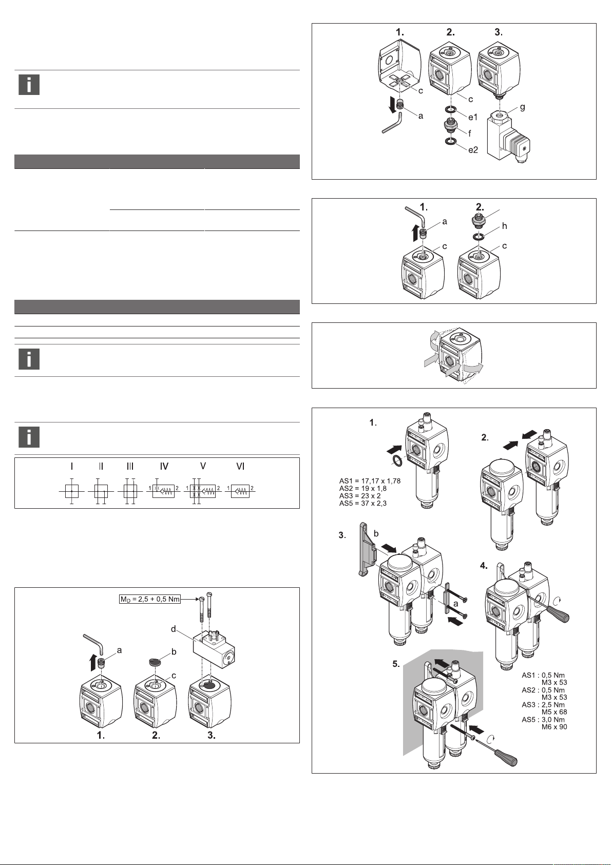
gAbb.2
1. Entfernen Sie die Verschlussschraube(a).
2. Legen Sie die Formdichtung(b) in die Dichtungsnut(c) des Luftanschlusses.
3. Setzen Sie den Drucksensor(d) auf den Flansch und schrauben Sie ihn fest.
5.2.2 Rohranschluss (AS1, AS2, AS3)
gAbb.3
1. Entfernen Sie die Verschlussschraube(a).
2. Dichten Sie den Doppelnippel(f) mit den Dichtungen(e1+e2) ab und schrau-
ben Sie den Doppelnippel (f) in den Verteiler ein.
Hinweis: Doppelnippel (f) muss separat bestellt werden, Dichtungen (e1+e2)
liegen dem Doppelnippel bei.
3. Schrauben Sie den Drucksensor(g) auf den Doppelnippel (f).
5.3 Zubehörkomponenten montieren
VORSICHT
Verletzungsgefahr bei Demontage oder Austausch unter Druck oder Spannung!
Demontage oder Austausch unter Druck oder anliegender elektrischer Spannung kann zu Verletzungen führen und das Produkt oder Anlagenteile beschädigen.
1. Schalten Sie den relevanten Anlagenteil drucklos und spannungsfrei, bevor
Sie das Produkt demontieren oder Teile austauschen.
2. Sichern Sie die Anlage gegen Wiedereinschalten.
8 Entsorgung
Entsorgen Sie das Produkt und das Kondensat nach den nationalen Bestimmungen Ihres Landes.
9 Erweiterung und Umbau
VORSICHT
Verletzungsgefahr bei Demontage oder Austausch unter Druck oder Spannung!
Demontage oder Austausch unter Druck oder anliegender elektrischer Spannung kann zu Verletzungen führen und das Produkt oder Anlagenteile beschädigen.
1. Schalten Sie den relevanten Anlagenteil drucklos und spannungsfrei, bevor
Sie das Produkt demontieren oder Teile austauschen.
2. Sichern Sie die Anlage gegen Wiedereinschalten.
9.1 Durchflussrichtung ändern
gAbb.5
Im Auslieferungszustand ist die Durchflussrichtung von links (1, IN) nach rechts
(2, OUT). Soll die Durchflussrichtung geändert werden, sind folgende Umbauten
am Produkt nötig:
9.1.1 Umbau Verteiler
Bei allen Komponenten erfolgt die Änderung der Durchflussrichtung durch einen
um 180° in der Vertikalachse gedrehten Einbau. Hierfür müssen die Gehäusedeckel gewechselt werden.
1. Lösen Sie den Gehäusedeckel von Vorder- und Rückseite.
2. Bringen Sie die Deckel auf den Gegenseiten wieder an. Der Deckel mit dem
AVENTICS-Logo zeigt nach vorne.
5.3.1 Rohranschluss (AS2, AS3)
gAbb.4
1. Entfernen Sie die Verschlussschraube(a).
2. Legen Sie die Flachdichtung (h) in die Dichtungsnut (c) des Luftanschlusses.
3. Schrauben Sie Zubehörkomponenten (i) wie Steckanschlüsse, Stutzen, Mehr-
fach-Anschlusszapfen ein.
9.1.2 Umbau der Komponenten bei DIC
Zur Änderung der Durchflussrichtung beim Verteiler DIC mit Mitteneinspeisung müssen die Komponenten umgebaut werden, deren
Durchflussrichtung von links nach rechts geht.
AVENTICS™ AS1 | AS2 | AS3 | AS5 | R412013438-BAL-001-AE | Deutsch 3
Page 4

10 Fehlersuche und Fehlerbehebung
a
i
Störung Mögliche Ursache Abhilfe
Druck-/Durchflussniveau wird
nicht erreicht oder baut sich
langsam ab.
Betriebsdruck zu gering • Höheren Betriebsdruck
einstellen
• Schlauchdurchmesser
prüfen
Leckage im Schlauch Schläuche und Schlauchver-
bindungen überprüfen
11 Technische Daten
Maximal zulässiger Druck, Temperaturbereich und Gewindeanschluss sind auf
den Produkten angegeben.
Allgemeine Daten
Einbaulage beliebig
Mediums-/ Umgebungs-temperatur min./
max.
Weitere technische Daten entnehmen Sie dem Online-Katalog.
-10°C /+50°C
Abb.3: Rohranschluss | Serie AS1, AS2, AS3
12 Anhang
Abbildungen: Ansicht variiert je nach Serie.
Abb.1: Schaltsymbole:
I = 2-fach;
II = 3-fach;
III = 4-fach;
IV = Rückschlagventil, 1-fach;
V = Rückschlagventil, 4-fach;
VI = Rückschlagventil, 0-fach
Abb.4: Zubehörkomponenten montieren | Serie AS2, AS3
Abb.5: Durchflussrichtung ändern: Gehäusedeckel wechseln
Abb.2: Drucksensor: Flanschmontage | Serie AS1, AS2, AS3, AS5
Abb.6: Verblockung und Befestigung mit Befestigungsbügel W03
AVENTICS™ AS1 | AS2 | AS3 | AS5 | R412013438-BAL-001-AE | Deutsch 4
Page 5

Abb.7: Befestigung mit Befestigungsplatte W01
Abb.8: Verblockung mit Verblockungssatz W04
Abb.9: Verblockung und Befestigung mit Verblockungssatz W05
AVENTICS™ AS1 | AS2 | AS3 | AS5 | R412013438-BAL-001-AE | Deutsch 5
Page 6

1 About this documentation
These instructions contain important information for the safe and appropriate assembly and commissioning of the product.
u Read these instructions carefully, especially chapterg2.Safety instructions
before you start working with the product.
1.1 Additional documentation
1. Also follow the instructions for the other system components.
2. Please also observe the generally relevant, statutory, and other binding regu-
lations of European and national legislation, and the national regulations for
accident prevention and environmental protection in your country.
1.2 Presentation of information
1.2.1 Warnings
In this documentation, there are warning notes before the steps whenever there
is a risk of personal injury or damage to equipment. The measures described to
avoid these hazards must be followed.
Structure of warnings
SIGNAL WORD
Hazard type and source
Consequences of non-observance
u Precautions
Meaning of the signal words
Qualified personnel are those who can recognize possible dangers and institute
the appropriate safety measures, due to their professional training, knowledge,
and experience, as well as their understanding of the relevant regulations pertaining to the work to be done. Qualified personnel must observe the rules relevant to the subject area.
2.3 General safety instructions
• Observe the valid local regulations to protect the environment in the country
of use and to avoid workplace accidents.
• Only use AVENTICS products that are in perfect working order.
• Examine the product for obvious defects, such as cracks in the housing or
missing screws, caps, or seals.
• Do not modify or convert the product.
• Persons who assemble, operate, disassemble, or maintain AVENTICS products
must not consume any alcohol, drugs, or pharmaceuticals that may affect
their ability to respond.
• The warranty will not apply if the product is incorrectly assembled.
• Do not place any improper mechanical loads on the product under any circumstances.
• Product warnings and information must be legible, i.e. not covered by paint,
etc.
2.4 Safety instructions related to the product and technology
• Lay cables and lines so that they cannot be damaged and no one can trip over
them.
• Do not operate the product in aggressive ambient air (e.g., solvent vapors).
CAUTION
Possible dangerous situation.
Failure to observe these notices may result in minor injuries or damage to
property.
1.2.2 Symbols
Recommendation for the optimum use of our products.
Observe this information to ensure the smoothest possible operation.
2 Safety instructions
The product has been manufactured according to the accepted rules of current
technology. Even so, there is a risk of injury or damage if the following general
safety instructions and the specific warnings given in this instruction manual are
not observed.
1. Please read all these instructions carefully before working with the product.
2. Keep these instructions in a location where they are accessible to all users at
all times.
3. Always include the operating instructions when you pass the product on to
third parties.
2.1 Intended use
The product is exclusively intended for installation in a machine or system, or for
combination with other components to form a machine or system. The product
may only be commissioned after it has been installed in the machine/system for
which it is intended.
Use is permitted only under the operating conditions and within the performance
limits listed in the technical data. Only use compressed air as the medium.
The product is technical equipment and is intended for professional use only.
Intended use includes having fully read and understood these instructions, espe-
cially chapterg2.Safety instructions.
3 Scope of delivery
• 1x distributor as ordered
• 1 set of operating instructions
• Additionally in case of AS2, AS3:
– 1x molded seal
– 1x flat gasket
4 About this product
Distributors are components of air preparation units and are used to distribute
compressed air. Pressure switches may be additionally mounted in flange and
pipe connections. The following versions are available:
• DIS: Standard distributor
• DIC: Distributor with center infeed
• DIN: Distributor with non-return valve
The following table lists assignment to the air preparation units:
Air preparation
units
AS1 DIS 2-fold I
AS2 DIS 3-fold II
AS3 DIS 4-fold III
AS5 DIS 2-fold I
Version Description Circuit symbols
See gFig.1
DIN Non-return valve, 1-fold IV
DIC 3-fold II
DIN Non-return valve, 1-fold IV
DIC 4-fold III
DIN Non-return valve,
4-fold
DIN Non-return valve,
0-fold
V
VI
2.2 Personnel qualifications
All tasks associated with the product require basic mechanical, pneumatic, and
electrical knowledge, as well as knowledge of the respective technical terms. In
order to ensure operational safety, these tasks may only be carried out by qualified personnel or an instructed person under the direction of qualified personnel.
AVENTICS™ AS1 | AS2 | AS3 | AS5 | R412013438-BAL-001-AE | English 6
5 Assembly, commissioning and operation
u Let the product acclimatize for several hours before commissioning, other-
wise, water may condense in the housing.
Page 7

CAUTION
Danger of injury if assembled under pressure or voltage!
Assembling when under pressure or electrical voltage can lead to injuries and
damage to the product or system components.
1. Make sure that the relevant system component is without pressure and
voltage before you assemble the product.
2. Protect the system against being restarted.
CAUTION
Sudden pressure increase during commissioning!
The system is exposed to sudden pressure on commissioning if no SSU filling
unit is used! This may result in dangerous erratic cylinder motions.
u Please ensure when commissioning a system without a SSU filling unit that
the cylinders are in their end position or that no danger can emit from
those not in end position.
CAUTION
System is operating under pressure!
Incorrect installation may damage the air preparation unit/apparatus and
cause serious injury.
u Before commissioning, check that all connections, ports, and maintenance
equipment have been correctly installed.
• Do not use high-pressure cleaners for cleaning.
• Do not use compressed air for cleaning (blowing off) the air preparation unit
or equipment.
7 Disassembly, exchange
CAUTION
Danger of injury in case of disassembly or replacement under pressure or
voltage!
Disassembling or replacement when under pressure or electrical voltage may
lead to injuries and damage to the product or system components.
1. Make sure that the relevant system part is without pressure or voltage be-
fore disassembling the product or exchanging parts.
2. Protect the system against being restarted.
8 Disposal
Dispose of the product and condensate in accordance with the national regulations in your country.
5.1 Mounting fastening elements W01, W03, W04 and W05
u Please heed figures gFig.7, gFig.6, gFig.8 and gFig.9.
5.2 Mounting the pressure sensor
On the AS5 series pressure sensors can only be flange-mounted.
5.2.1 Flange mounting
gFig.2
1. Remove the blanking screw(a).
2. Insert the molded seal(b) in the seal channel(c) of the air connection.
3. Place the pressure sensor (d) on the flange and screw it tight.
5.2.2 Pipe connection (AS1, AS2, AS3)
gFig.3
1. Remove the blanking screw(a).
2. Close the double nipple(f) with the seals(e1+e2) and screw the double nipple
(f) into the distributor.
Notice: The double nipple (f) must be ordered separately, seals (e1+e2) are included with the double nipple.
3. Screw the pressure sensor (g) onto the double nipple (f).
5.3 Mounting accessory components
5.3.1 Pipe connection (AS2, AS3)
gFig.4
1. Remove the blanking screw(a).
2. Insert the flat gasket(h) in the seal channel(c) of the air connection.
3. Screw in the accessory components (i) such as push-in fittings, connection
pieces, multiple adapters.
6 Service and repairs
6.1 Cleaning and servicing
• Close all openings with suitable safety devices so that no cleaning agent can
enter into the system.
• Never use solvents or aggressive detergents. Only clean the product using a
slightly damp cloth. Only use water and, if necessary, a mild detergent.
9 Conversion and extension
CAUTION
Danger of injury in case of disassembly or replacement under pressure or
voltage!
Disassembling or replacement when under pressure or electrical voltage may
lead to injuries and damage to the product or system components.
1. Make sure that the relevant system part is without pressure or voltage be-
fore disassembling the product or exchanging parts.
2. Protect the system against being restarted.
9.1 Change flow direction
gFig.5
On delivery the flow direction is from left (1,IN) to right (2,OUT). The following
conversion on the product is necessary if the flow direction is to be changed:
9.1.1 Distributor conversion
On all components, the flow direction change is performed by rotating an installation by 180° around the vertical axis. The housing covers need to be changed
for the purpose.
1. Release the housing cover at the front and back.
2. Re-attach the covers at the opposite sides with the cover bearing the
AVENTICS logo facing to the front.
9.1.2 Component conversion on the DIC
Components with a flow direction from left to right need to be converted to change the flow direction on the DIC distributor with center
infeed.
10 Troubleshooting
Malfunction Possible cause Remedy
Pressure/flow level is not
reached or drops off slowly.
Operating pressure too low • Set higher operating pres-
sure
• Check tubing diameter
Leak on tubing Check tubing and tubing con-
nections
AVENTICS™ AS1 | AS2 | AS3 | AS5 | R412013438-BAL-001-AE | English 7
Page 8

11 Technical data
a
i
Maximum permissible pressure, temperature range, and thread connection are
indicated on the products.
General data
Mounting orientation Any
Min./max. medium/ambient temperature -10°C /+50°C
Further technical data can be found in our online catalog.
12 Appendix
Figures: View varies according to the series.
Fig.1: Circuit symbols:
I = 2-fold;
II = 3-fold;
III = 4-fold;
IV = Non-return valve, 1-fold;
V = Non-return valve, 4-fold
VI = Non-return valve, 0-fold
Fig.4: Mounting accessory components | series AS2, AS3
Fig.5: Changing the flow direction: changing the housing cover
Fig.2: Pressure sensor: flange mounting | series AS1, AS2, AS3, AS5
Fig.3: Pipe connection | series AS1, AS2, AS3
Fig.6: Block assembly and mounting with mounting clip W03
AVENTICS™ AS1 | AS2 | AS3 | AS5 | R412013438-BAL-001-AE | English 8
Page 9

Fig.7: Mounting with mounting plate W01
Fig.8: Block assembly with W04 block assembly kit
Fig.9: Block assembly and mounting with W05 block assembly kit
AVENTICS™ AS1 | AS2 | AS3 | AS5 | R412013438-BAL-001-AE | English 9
Page 10

1 A propos de cette documentation
Cette notice contient des informations importantes pour monter et mettre en
service le produit de manière sûre et conforme.
u Lire entièrement cette notice et particulièrement le chapitreg2.Consignes
de sécurité avant de travailler avec le produit.
1.1 Documentations complémentaires
1. Consulter également les notices des autres composants de l’installation.
2. Observer en outre les dispositions légales ainsi que toute autre réglementa-
tion à caractère obligatoire en vigueur et généralement applicable en Europe
ainsi que dans le pays d’utilisation, de même que les consignes de prévention
d’accident et de sauvegarde de l’environnement.
1.2 Présentation des informations
1.2.1 Avertissements
Cette documentation contient des remarques d’avertissement préalables aux séquences de travail lorsqu’un risque de dommage corporel ou matériel subsiste.
Les mesures décrites pour éviter ces risques doivent être suivies.
Structure des avertissements
MOT-CLE
Type et source de risque
Conséquences du non-respect
u Précautions
Signification des mots-clés
ATTENTION
Situation dangereuse potentielle.
Le non-respect de ces consignes risque d’entraîner de légères blessures ou des
dommages matériels.
1.2.2 Symboles
Recommandation pour une utilisation optimale de nos produits.
Respecter ces informations pour garantir un fonctionnement optimal.
2 Consignes de sécurité
Le produit a été fabriqué selon les règles techniques généralement reconnues.
Des dommages matériels ou corporels peuvent néanmoins survenir si les
consignes de sécurité générales suivantes ainsi que les avertissements précédant
les consignes d’utilisation contenus dans la présente notice ne sont pas respectés.
1. Lire entièrement et attentivement la notice d’instruction avant de travailler
avec le produit.
2. La conserver de sorte qu’elle soit accessible à tout instant à tous les utilisateurs.
3. Toujours transmettre le produit à de tierces personnes accompagné de la notice d’instruction respective.
2.1 Utilisation conforme
Le produit a exclusivement été conçu pour être posé sur une machine ou une installation ou pour être assemblé à d’autres composants sur une machine ou une
installation. La mise en service du produit n’est autorisée que lorsque celui-ci est
entièrement monté sur la machine ou l’installation à laquelle il a été destiné.
Respecter les conditions de fonctionnement et les limites de puissance figurant
dans les données techniques. Comme fluide, utiliser uniquement de l’air comprimé.
Le produit est un outil de travail technique non destiné à un usage dans le domaine privé.
L’utilisation conforme inclut le fait d’avoir lu et compris ce mode d’emploi dans
son intégralité et en particulier le chapitreg2.Consignes de sécurité.
2.2 Qualification du personnel
L’ensemble des activités liées au produit exige des connaissances mécaniques,
électriques et pneumatiques fondamentales, ainsi que la connaissance des
termes techniques correspondants. Afin d’assurer un fonctionnement en toute
sécurité, ces travaux ne doivent par conséquent être effectués que par des techniciens ou par une personne ayant reçu les instructions nécessaires mais restant
sous la direction et la surveillance d’un technicien.
Un technicien est capable d’évaluer les tâches qui lui sont confiées, de reconnaître d’éventuels dangers et de prendre les mesures de sécurité adéquates
grâce à sa formation spécialisée, ses connaissances et son expérience, ainsi qu’à
ses connaissances des directives en vigueur. Il doit respecter les règles spécifiques en vigueur.
2.3 Consignes générales de sécurité
• Respecter les consignes de prévention d’accidents et de protection de l’environnement en vigueur dans le pays d’utilisation et au poste de travail.
• Utiliser les produits AVENTICS exclusivement lorsque leur état technique est
irréprochable.
• S’assurer de l’absence de vices manifestes ou de dégâts dus au transport sur
le produit, par exemple un boîtier fissuré, des vis, couvercles de protection ou
joints manquants.
• Il est généralement interdit de modifier ou de transformer le produit.
• Les personnes montant, commandant, démontant ou entretenant des produits AVENTICS ne doivent pas être sous l’emprise d’alcool, de drogues ou de
médicaments divers pouvant altérer leur temps de réaction.
• La garantie n’est plus valable en cas de montage incorrect.
• Ne surcharger en aucun cas le produit de manière mécanique de par une utilisation non conforme.
• Les avertissements et indications concernant le produit doivent rester lisibles
et ne pas être recouverts par de la peinture ou autre.
2.4 Consignes de sécurité selon le produit et la technique
• Poser les câbles et les conduites de sorte que ceux-ci ne soient pas endommagés et que personne ne puisse trébucher dessus.
• Le produit ne doit pas fonctionner dans un air ambiant agressif (p. ex. avec vapeurs de solvants).
3 Fourniture
• 1répartiteur selon la commande
• 1 notice d’instruction
• Pour AS2 et AS3, la fourniture comprend également:
– 1joint moulé
– 1joint plat
4 A propos de ce produit
Les répartiteurs sont des composants des unités de traitement de l'air qui servent
à répartir l'air comprimé. De plus, il est possible de monter des manostats avec
fixation par bride et raccordement direct. Les versions suivantes sont disponibles:
• DIS: répartiteur standard
• DIC: répartiteur avec alimentation centrale
• DIN: répartiteur avec clapet anti-retour
Le tableau suivant détaille l'affectation aux unités de traitement de l'air:
Unité de traitement de l’air
AS1 DIS Double I
AS2 DIS Triple II
AS3 DIS Quadruple III
Version Description Symbole de com-
mutation
Voir gFig.1
DIN Clapet anti-retour, simple IV
DIC Triple II
DIN Clapet anti-retour, simple IV
DIC Quadruple III
AVENTICS™ AS1 | AS2 | AS3 | AS5 | R412013438-BAL-001-AE | Français 10
Page 11

Unité de traitement de l’air
AS5 DIS Double I
Version Description Symbole de com-
mutation
Voir gFig.1
DIN Clapet anti-retour,
quadruple
DIN Clapet anti-retour,
sans battant
5.3 Montage des accessoires
V
VI
5.3.1 Raccordement direct (AS2, AS3)
gFig.4
1. Retirer le bouchon à visser(a).
2. Poser le joint plat(h) dans la rainure(c) du raccord pneumatique.
3. Visser les accessoires(i), comme des raccords instantanés, des raccords ou
des raccords filetés multiples.
5 Montage, mise en service et fonctionnement
u Avant la mise en service du produit, laisser le produit s’acclimater pendant
quelques heures, de l’eau de condensation pouvant sinon se former dans le
boîtier.
ATTENTION
Risque de blessure dû à un montage sous pression ou sous tension!
Le montage sous pression ou sous tension électrique peut provoquer des blessures et endommager le produit ou des parties de l’installation.
1. Mettre la partie pertinente de l’installation hors pression et hors tension
avant de monter le produit.
2. Protéger l’installation de toute remise en marche.
ATTENTION
Brusque augmentation de la pression lors de la mise en service!
Si aucune unité de mise en pression SSU n’est employée, l'installation est brusquement mise sous pression lors de la mise en service! Cela peut provoquer
des mouvements dangereux et saccadés du vérin.
u Lors de la mise en service d’une installation sans unité de mise en pression
SSU, veiller à ce que les vérins se trouvent en position finale ou à ce que les
vérins qui ne sont pas en position finale ne présentent aucun danger.
ATTENTION
Lors du fonctionnement, l’installation est sous pression!
En cas d’installation non conforme, l’unité/l’appareil de traitement de l’air
risque de subir des dommages, et des blessures graves peuvent être causées.
u Avant de procéder à la mise en service, vérifier que tous les raccords et ap-
pareils de traitement de l’air sont installés correctement.
5.1 Montage des éléments de fixation W01, W03, W04 et W05
u Tenir compte des illustrations gFig.7, gFig.6, gFig.8 et gFig.9.
6 Entretien et maintenance
6.1 Nettoyage et entretien
• Obturer toutes les ouvertures à l’aide de dispositifs de protection appropriés
afin qu’aucun produit nettoyant ne puisse s’infiltrer dans le système.
• Ne jamais utiliser de solvants ou de produits de nettoyage agressifs. Nettoyer
le produit uniquement avec un chiffon légèrement humide. Pour cela, utiliser
exclusivement de l’eau et éventuellement un détergent doux.
• N’utiliser aucun nettoyeur haute pression pour le nettoyage.
• Ne pas utiliser d’air comprimé pour nettoyer (soufflage) l’unité ou des appareils de traitement de l’air.
7 Démontage, remplacement
ATTENTION
Risque de blessures en cas de démontage ou de remplacement sous pression ou sous tension!
Le démontage ou remplacement sous pression ou sous tension électrique en
présence peut provoquer des blessures et endommager le produit ou des parties de l’installation.
1. Mettre la partie pertinente de l’installation hors pression et hors tension
avant de démonter le produit ou de remplacer des pièces.
2. Protéger l’installation de toute remise en marche.
8 Mise au rebut
Eliminer le produit et le condensat selon les directives du pays concerné.
9 Transformation et extension
5.2 Montage du capteur de pression
Pour la sérieAS5, les capteurs de pressions ne peuvent faire l'objet que
d'un montage par bride.
5.2.1 Montage par bride
gFig.2
1. Retirer le bouchon à visser(a).
2. Poser le joint moulé(b) dans la rainure(c) du raccord pneumatique.
3. Poser le capteur de pression(d) sur la bride et le visser à fond.
5.2.2 Raccordement direct (AS1, AS2, AS3)
gFig.3
1. Retirer le bouchon à visser(a).
2. Munir le manchon double(f) de joints(e1+e2) et visser le manchon double (f)
dans le répartiteur.
Remarque: le manchon double (f) doit être commandé séparément, les joints
(e1+e2) sont fournis avec le manchon double.
3. Visser le capteur de pression(g) sur le manchon double (f).
Risque de blessures en cas de démontage ou de remplacement sous pression ou sous tension!
Le démontage ou remplacement sous pression ou sous tension électrique en
présence peut provoquer des blessures et endommager le produit ou des parties de l’installation.
1. Mettre la partie pertinente de l’installation hors pression et hors tension
avant de démonter le produit ou de remplacer des pièces.
2. Protéger l’installation de toute remise en marche.
9.1 Modification du sens du débit
gFig.5
A la livraison de l’appareil, le sens de débit va de la gauche (1, IN) vers la droite (2,
OUT). S’il doit être modifié, le produit doit être transformé de la manière suivante:
9.1.1 Transformation du répartiteur
Pour tous les composants, la modification du sens de débit s’effectue en tournant
le composant de 180° sur l’axe vertical. Pour cela, il faut remplacer les couvercles
de boîtiers.
1. Dévisser les couvercles du boîtier en face avant et en face arrière.
ATTENTION
AVENTICS™ AS1 | AS2 | AS3 | AS5 | R412013438-BAL-001-AE | Français 11
Page 12
2. Monter à nouveau le couvercle sur les côtés opposés. Le couvercle avec le lo-
a
i
go AVENTICS doit être positionné vers l’avant.
9.1.2 Transformation des composants pour DIC
Pour modifier le sens du débit du répartiteur DIC avec alimentation
centrale, les composants dont le sens du débit s'effectue de gauche à
droite doivent être transformés.
10 Recherche et élimination de défauts
Défaillance Cause possible Remède
Le niveau de pression/du débit n’est pas atteint ou baisse
lentement.
Pression de service trop faible • Régler une pression de
service plus élevée
• Contrôler le diamètre du
tuyau
Fuite du tuyau Vérifier les flexibles et les rac-
cords cannelés
11 Données techniques
La pression maximale autorisée, la plage de température et le raccord fileté sont
indiqués sur les produits.
Données générales
Position de montage Indifférente
Température de fluide/ ambiante min./ max. -10°C /+50°C
Fig.3: Raccordement direct | Séries AS1, AS2, AS3
Fig.4: Montage des accessoires | Séries AS2, AS3
D’autres données techniques figurent dans le catalogue en ligne.
12 Annexe
Figures: la vue peut varier en fonction de la série.
Fig.1: Symboles de commande:
I = double;
II = triple;
III = quadruple;
IV = clapet anti-retour, simple;
V = clapet anti-retour, quadruple;
VI = clapet anti-retour, sans battant
Fig.5: Modification du sens du débit: remplacement du couvercle de boîtier
Fig.2: Capteur de pression: montage par bride | Séries AS1, AS2, AS3, AS5
Fig.6: Blocage montage en batterie et fixation avec l’étrier de fixation W03
AVENTICS™ AS1 | AS2 | AS3 | AS5 | R412013438-BAL-001-AE | Français 12
Page 13

Fig.7: Fixation avec la plaque de fixation W01
Fig.8: Blocage montage en batterie avec kit de montage en batterie W04
Fig.9: Blocage montage en batterie et fixation avec kit de montage en batterie
W05
AVENTICS™ AS1 | AS2 | AS3 | AS5 | R412013438-BAL-001-AE | Français 13
Page 14

1 Sulla presente documentazione
La presente documentazione contiene importanti informazioni per trasportare,
installare e azionare il prodotto nel rispetto delle norme e della sicurezza.
u Leggere queste istruzioni ed in particolar modo il capitolog2.Indicazioni di
sicurezza in tutte le sue parti prima di adoperare il prodotto.
1.1 Documentazione aggiuntiva
1. Osservare anche le istruzioni dei restanti componenti dell'impianto.
2. Osservare inoltre le norme vigenti e generalmente riconosciute della legisla-
zione europea o nazionale nonché le norme antinfortunistiche e di tutela
dell'ambiente in vigore nel proprio paese.
1.2 Presentazione delle informazioni
1.2.1 Avvertenze
In queste istruzioni le azioni da eseguire sono precedute da note di avviso, se esiste pericolo di danni a cose o persone. Le misure descritte per la prevenzione di
pericoli devono essere rispettate.
Struttura delle avvertenze
Per personale specializzato si intendono coloro i quali, grazie alla propria formazione professionale, alle proprie conoscenze ed esperienze e alle conoscenze delle disposizioni vigenti, sono in grado di valutare i lavori commissionati, individuare i possibili pericoli e adottare le misure di sicurezza adeguate. Ilpersonale specializzato deve rispettare le norme in vigore specifiche del settore.
2.3 Avvertenze di sicurezza generali
• Osservare le prescrizioni antinfortunistiche e di protezione ambientale vigenti
nello stato in cui l’apparecchio viene usato e sul posto di lavoro.
• Utilizzare i prodotti AVENTICS esclusivamente in condizioni tecniche perfette.
• Verificare eventuali anomalie del prodotto, come per esempio fessure nel corpo oppure viti, cuffie, guarnizioni mancanti.
• Non è consentito in generale modificare o trasformare il prodotto.
• Le persone che si occupano del montaggio, del funzionamento, dello smontaggio o della manutenzione dei prodotti AVENTICS non devono essere sotto
effetto di alcool, droga o farmaci che alterano la capacità di reazione.
• La garanzia decade in caso di montaggio errato.
• Non sottoporre in nessun caso il prodotto a sollecitazioni meccaniche.
• Le avvertenze e le indicazioni relative al prodotto non devono essere coperte
da vernice ecc., ma devono essere sempre chiaramente leggibili.
PAROLA DI SEGNALAZIONE
Natura e fonte del pericolo
Conseguenze di una mancata osservanza
u Precauzioni
Significato delle parole di segnalazione
ATTENZIONE
Possibile situazione pericolosa.
La mancata osservanza di questi avvertimenti può causare lesioni di lieve entità
o danni materiali.
1.2.2 Simboli
Si raccomanda di attenersi al corretto utilizzo dei nostri prodotti.
Rispettare il presente documento al fine di garantire il funzionamento
regolare.
2 Indicazioni di sicurezza
Il prodotto è stato realizzato in base alle regole della tecnica generalmente riconosciute. Nonostante ciò esiste il pericolo di danni a cose e persone, se non vengono osservate le istruzioni ed avvertenze di sicurezza di base illustrate di seguito, prima di intraprendere qualsiasi azione.
1. Leggere perciò attentamente queste istruzioni in ogni parte prima di adopera-
re il prodotto.
2. Conservare le istruzioni in modo che siano sempre accessibili a tutti gli utenti.
3. Se si consegna il prodotto a terzi, allegare sempre le istruzioni per l’uso.
2.1 Utilizzo a norma
Il prodotto è destinato esclusivamente al montaggio in una macchina o in un impianto o all’integrazione con altri componenti in una macchina o in un impianto.
Il prodotto deve essere messo in funzione solo dopo il montaggio nella macchina/nell’impianto al/alla quale è destinato.
Rispettare le condizioni di funzionamento e i limiti di potenza riportati nei dati
tecnici. Utilizzare come fluido esclusivamente aria compressa.
Il prodotto è uno strumento di lavoro tecnico non destinato all’uso privato.
L’uso a norma comprende anche la lettura e la comprensione di queste istruzioni
ed in particolar modo del capitolog2.Indicazioni di sicurezza.
2.4 Indicazioni di sicurezza sul prodotto e sulla tecnologia
• Disporre i cavi e i collegamenti in modo tale che non vengano danneggiati e
che nessuno ci inciampi.
• Il prodotto non deve essere impiegato in atmosfera aggressiva (peres. vapori
di solventi).
3 Fornitura
• 1 distributore come da ordinazione
• 1 esemplare delle istruzioni per l‘uso
• Inoltre per AS2, AS3:
– 1 guarnizione sagomata
– 1 guarnizione piatta
4 Descrizione del prodotto
I distributori sono componenti dei gruppi di trattamento con la funzione di distribuire l’aria compressa. Inoltre, è possibile montare il pressostato in raccordi a
flangia e a compressione. Sono disponibili le seguenti esecuzioni:
• DIS: distributore standard
• DIC: distributore con alimentazione centrale
• DIN: distributore con valvola antiritorno
Nella seguente tabella è illustrata l’assegnazione ai gruppi di trattamento:
Gruppo di trattamento
AS1 DIS a 2 vie I
AS2 DIS a 3 vie II
AS3 DIS a 4 vie III
AS5 DIS a 2 vie I
Esecuzione Descrizione Simboli di com-
DIN valvola antiritorno, a 1via IV
DIC a 3 vie II
DIN valvola antiritorno, a 1via IV
DIC a 4 vie III
DIN valvola antiritorno,
a 4 vie
DIN valvola antiritorno,
a 0 vie
mutazione
ved. gFig.1
V
VI
2.2 Qualifica del personale
Tutte le attività legate al prodotto richiedono conoscenze basilari meccaniche,
elettriche e pneumatiche, nonché conoscenze dei relativi termini tecnici. Pergarantire la sicurezza d’esercizio queste attività devono essere perciò eseguite solo
da personale specializzato in materia o da una persona istruita sotto la guida e la
sorveglianza di personale qualificato.
AVENTICS™ AS1 | AS2 | AS3 | AS5 | R412013438-BAL-001-AE | Italiano 14
Page 15

5 Montaggio, messa in funzione e uso
u Prima della messa in funzione, attendere alcune ore che il prodotto si adatti
all’atmosfera ambiente, per evitare la formazione di condensa nell’alloggiamento.
ATTENZIONE
Pericolo di lesioni dovuto a montaggio sotto pressione o tensione!
Il montaggio sotto pressione o con tensione elettrica applicata può provocare
lesioni e danneggiare il prodotto o parti dell'impianto.
1. Togliere l'alimentazione elettrica e pneumatica della parte dell'impianto ri-
levante prima di montare il prodotto.
2. Proteggere l'impianto da riaccensione.
6 Manutenzione e riparazione
6.1 Pulizia e cura
• Chiudere tutte le aperture con dispositivi di protezione adeguati, in modo da
evitare la penetrazione di detergenti nel sistema.
• Non usare mai solventi o detergenti aggressivi. Pulire il prodotto esclusivamente con un panno morbido e umido. Usare a tal scopo esclusivamente acqua ed eventualmente un detergente delicato.
• Non utilizzare idropulitrici ad alta pressione per la pulizia.
• Non utilizzare aria compressa per la pulizia (soffiatura) dei gruppi di trattamento o degli apparecchi di manutenzione.
ATTENZIONE
Aumento improvviso della pressione durante la messa in funzione!
Se non viene utilizzata nessuna unità di riempimentoSSU, durante la messa in
funzione l'impianto è sottoposto a pressione improvvisa! Per questo possono
verificarsi movimenti dei cilindri a scatti e pericolosi.
u Assicurarsi che durante la messa in funzione di un impianto senza unità di
riempimento SSU i cilindri si trovino nella posizione di fine corsa, e che, in
caso contrario, non possano rappresentare alcun pericolo.
ATTENZIONE
L'impianto durante il funzionamento è sottoposto a pressione!
Un'installazione non idonea può provocare danni al gruppo di trattamento/
all'apparecchio di manutenzione e portare a lesioni gravi.
u Prima della messa in funzione controllare la corretta installazione di tutti i
collegamenti, raccordi e apparecchi di manutenzione.
5.1 Montaggio degli elementi di fissaggio W01, W03, W04 e W05
u Osservare le FiguregFig.7, gFig.6, gFig.8 e gFig.9.
5.2 Montaggio del sensore di pressione
Nella serie AS5 i sensori di pressione possono essere montati solo a
flangia.
5.2.1 Montaggio a flangia
gFig.2
1. Rimuovere la vite di chiusura(a).
2. Inserire la guarnizione sagomata(b) nell'apposita scanalatura(c) del raccordo
pneumatico.
3. Posizionare il sensore di pressione(d) sulla flangia e serrarlo.
5.2.2 Raccordo a compressione (AS1, AS2, AS3)
gFig.3
1. Rimuovere la vite di chiusura(a).
2. Chiudere ermeticamente il nipplo doppio(f) con guarnizioni(e1+e2) e avvita-
re il nipplo doppio (f) nel distributore.
Nota: il nipplo doppio (f) deve essere ordinato separatamente; le guarnizioni
(e1+e2) sono comprese nella fornitura del nipplo doppio.
3. Avvitare il sensore di pressione(g) sul nipplo doppio (f).
5.3 Montaggio dei componenti accessori
7 Smontaggio, sostituzione
ATTENZIONE
Pericolo di ferimento dovuto allo smontaggio o alla sostituzione in pressione o in tensione elettrica!
Lo smontaggio o la sostituzione in pressione o in tensione elettrica può provocare ferimenti e danneggiare il prodotto o parti dell'impianto.
1. Togliere l'alimentazione elettrica e pneumatica della parte dell'impianto ri-
levante prima di smontare il prodotto o sostituire dei componenti.
2. Proteggere l'impianto da riaccensione.
8 Smaltimento
Smaltire il prodotto e la condensa nel rispetto delle norme vigenti nel proprio
paese.
9 Ampliamento e trasformazione
ATTENZIONE
Pericolo di ferimento dovuto allo smontaggio o alla sostituzione in pressione o in tensione elettrica!
Lo smontaggio o la sostituzione in pressione o in tensione elettrica può provocare ferimenti e danneggiare il prodotto o parti dell'impianto.
1. Togliere l'alimentazione elettrica e pneumatica della parte dell'impianto ri-
levante prima di smontare il prodotto o sostituire dei componenti.
2. Proteggere l'impianto da riaccensione.
9.1 Modifica della direzione di flusso
gFig.5
Alla consegna la direzione di flusso è da sinistra (1, IN) verso destra (2, OUT). Per
modificare la direzione di flusso sono necessarie le seguenti modifiche al prodotto:
9.1.1 Trasformazione distributore
Per tutti i componenti la modifica della direzione di flusso avviene mediante un
montaggio ruotato di 180° sull’asse verticale. A tale scopo è necessario sostituire
i coperchi dei corpi.
1. Svitare il coperchio del corpo dal lato anteriore e posteriore.
2. Riapplicare il coperchio sui lati opposti. Il coperchio con il logo AVENTICS è ri-
volto in avanti.
5.3.1 Raccordo a compressione (AS2, AS3)
gFig.4
1. Rimuovere la vite di chiusura(a).
2. Inserire la guarnizione piatta (h) nell'apposita scanalatura (c) del raccordo
pneumatico.
3. Avvitare i componenti accessori (i) come raccordi ad innesto, manicotti, spi-
notti di collegamento multipli.
9.1.2 Trasformazione dei componenti nel DIC
Per modificare la direzione di flusso nel distributore DIC con alimentazione centrale è necessario trasformare i componenti la cui direzione
di flusso è da sinistra a destra.
AVENTICS™ AS1 | AS2 | AS3 | AS5 | R412013438-BAL-001-AE | Italiano 15
Page 16

10 Ricerca e risoluzione errori
a
i
Disturbo Causa possibile Soluzione
Il livello di pressione/portata
non viene raggiunto o diminuisce lentamente.
Pressione di esercizio troppo
bassa
Perdita nel tubo flessibile Controllare i tubi flessibili e i
• Impostare una pressione
di esercizio maggiore
• Verificare il diametro del
tubo flessibile
rispettivi collegamenti
11 Dati tecnici
La pressione massima consentita, l’intervallo di temperatura e il tipo di raccordo
filettato sono indicati sui prodotti.
Dati generali
Posizione di montaggio Qualsiasi
Temperatura del fluido/ambiente min./max. -10°C /+50°C
Per ulteriori dati tecnici consultare il catalogo online.
12 Appendice
Figure: l'immagine varia in base alla serie.
Fig.3: Raccordo a compressione | Serie AS1, AS2, AS3
Fig.4: Montaggio dei componenti accessori | Serie AS2, AS3
Fig.1: Simboli di commutazione:
I = a 2 vie;
II = a 3 vie;
III = a 4 vie;
IV = valvola antiritorno, a 1 via;
V = valvola antiritorno, a 4 vie;
VI = valvola antiritorno, 0vie
Fig.2: Sensore di pressione: montaggio a flangia | Serie AS1, AS2, AS3, AS5
Fig.5: Modifica della direzione di flusso: sostituzione del coperchio del corpo
Fig.6: Montaggio in batteria e fissaggio con staffa di fissaggio W03
AVENTICS™ AS1 | AS2 | AS3 | AS5 | R412013438-BAL-001-AE | Italiano 16
Page 17

Fig.7: Fissaggio con piastra di fissaggio W01
Fig.8: Montaggio in batteria con set per il montaggio in batteria W04
Fig.9: Montaggio in batteria e fissaggio con set per il montaggio in batteria W05
AVENTICS™ AS1 | AS2 | AS3 | AS5 | R412013438-BAL-001-AE | Italiano 17
Page 18

1 Acerca de esta documentación
Estas instrucciones contienen información importante para montar y poner en
funcionamiento el producto de un modo seguro y apropiado.
u Lea estas instrucciones por completo y, sobre todo, el capítulog2.Indicacio-
nes de seguridad antes de empezar a trabajar con el producto.
1.1 Documentación adicional
1. Tenga en cuenta también las instrucciones de los demás componentes de la
instalación.
2. Asimismo, tenga en cuenta las normativas y reglamentos aplicables de las le-
gislaciones europea y nacional, así como las disposiciones vigentes en su país
relativas a prevención de accidentes laborales y protección del medio ambiente.
1.2 Presentación de la información
1.2.1 Advertencias
Esta documentación incluye avisos de advertencia antes de los pasos siempre
que exista riesgo de daños personales o materiales en el equipo. Se deberán cumplir las medidas descritas para evitar dichos peligros.
Estructura de las advertencias
PALABRA DE ADVERTENCIA
Tipo de peligro y origen
Consecuencias derivadas de la no observancia
u Precauciones
2.2 Cualificación del personal
Es necesario tener conocimientos básicos de mecánica, electrónica y neumática,
así como de la terminología pertinente para realizar las tareas relacionadas con el
producto. Para garantizar la seguridad de funcionamiento, solamente personal
cualificado o bien otra persona supervisada por una persona cualificada podrá realizar estas actividades.
Por personal cualificado se entiende una persona que, en virtud de su formación
especializada, sus conocimientos y experiencia, así como su conocimiento acerca
de las normas vigentes, puede evaluar los trabajos que se le han encomendado,
detectar potenciales peligros y adoptar medidas de seguridad adecuadas. Un especialista debe cumplir las reglas pertinentes específicas del ramo.
2.3 Indicaciones de seguridad generales
• Observe las prescripciones vigentes para evitar accidentes y respetar el medio
ambiente en el país en el que se vaya a utilizar el sistema y en el puesto de trabajo.
• Utilice los productos de AVENTICS solo si no presentan problemas técnicos.
• Compruebe si el producto presenta algún defecto visible como, p.ej., grietas
en la carcasa, o si faltan tornillos, cubiertas de protección o juntas.
• Como norma general, no está permitido modificar ni transformar el producto.
• Las personas que montan, manejan y desmontan productos de AVENTICS o
realizan su mantenimiento no deben encontrarse bajo la influencia del alcohol, drogas o medicamentos que pudieran afectar a la capacidad de reacción.
• La garantía prescribe en el caso de un montaje defectuoso.
• En ninguna circunstancia debe someter el producto a cargas no admisibles.
• Las advertencias e información sobre el producto no deben quedar cubiertas,
p.ej., por pintura, sino que deben ser siempre perfectamente legibles.
Significado de las palabras de advertencia
ATENCIÓN
Posible situación peligrosa.
No respetar estas indicaciones podría ocasionar lesiones personales leves o da-
ños materiales.
1.2.2 Símbolos
Recomendaciones para una utilización óptima de nuestros productos.
Tenga en cuenta esta información para garantizar el mejor funciona-
miento posible.
2 Indicaciones de seguridad
Este producto ha sido fabricado conforme a las reglas de la técnica generalmente
conocidas. A pesar de ello, existe peligro de daños personales y materiales si no
se tienen en cuenta las indicaciones básicas de seguridad señaladas a continuación ni los carteles de advertencia ante indicaciones de manejo que aparecen en
estas instrucciones.
1. Lea estas instrucciones con detenimiento y por completo antes de trabajar
con el producto.
2. Guarde estas instrucciones en un lugar al que siempre puedan acceder fácil-
mente todos los usuarios.
3. Entregue siempre el producto a terceros junto con las instrucciones de servi-
cio.
2.1 Utilización conforme a las especificaciones
El producto está concebido exclusivamente para montarse en una máquina o instalación o para ensamblarse con otros componentes para formar una máquina o
instalación. El producto no debe ponerse en servicio hasta que esté montado en
la máquina/instalación para la que fue concebido.
Respete las condiciones de servicio y los límites de potencia mencionados en los
datos técnicos. Como medio, únicamente se puede utilizar aire comprimido.
El producto es un material de trabajo técnico y no está diseñado para uso privado.
La utilización conforme a las especificaciones también incluye que se hayan leído
y entendido estas instrucciones y, en especial, el capítulo g2.Indicaciones de seguridad.
2.4 Indicaciones de seguridad según producto y tecnología
• Coloque los cables y los conductos de manera que no resulten dañados y que
nadie pueda tropezar con ellos.
• El producto no se debe poner en funcionamiento en una zona con aire ambiente agresivo (p.ej., donde haya vapores de disolvente).
3 Volumen de suministro
• 1 distribuidor según pedido
• 1 instrucciones de servicio
• Con AS2, AS3 adicionalmente:
– 1 junta moldeada
– 1 junta plana
4 Sobre este producto
Los distribuidores son componentes de unidades de mantenimiento y sirven para
distribuir el aire comprimido. Adicionalmente pueden montarse presostatos en
conexiones por brida y conexiones de tubo. Están disponibles las siguientes versiones:
• DIS: distribuidor estándar
• DIC: distribuidor con alimentación central
• DIN: distribuidor con válvula antirretorno
La tabla siguiente muestra la asignación a las unidades de mantenimiento:
Unidad de mantenimiento
AS1 DIS 2-ble I
AS2 DIS 3-ble II
AS3 DIS 4-ble III
AS5 DIS 2-ble I
Versión Descripción Símbolos de con-
DIN Válvula antirretorno, 1-ple IV
DIC 3-ble II
DIN Válvula antirretorno, 1-ple IV
DIC 4-ble III
DIN Válvula antirretorno,
4-ble
mutación
véase gFig.1
V
AVENTICS™ AS1 | AS2 | AS3 | AS5 | R412013438-BAL-001-AE | Español 18
Page 19

Unidad de mantenimiento
Versión Descripción Símbolos de con-
DIN Válvula antirretorno,
0-ble
mutación
véase gFig.1
VI
5 Montaje, puesta en servicio y funcionamiento
u Deje que el producto se aclimate durante algunas horas antes de ponerlo en
servicio, ya que de lo contrario se podría condensar agua en la carcasa.
5.3 Montar accesorios
5.3.1 Conexión tubo (AS2, AS3)
gFig.4
1. Retire el tornillo de cierre (a).
2. Introduzca la junta plana (b) en la ranura de junta(c) de la conexión del aire.
3. Enrosque los accesorios (i) tales como conexiones, racores, pivotes múltiples.
6 Mantenimiento y reparación
ATENCIÓN
¡Peligro de lesiones por montaje con presión o tensión!
El montaje con presencia de tensión eléctrica o presión puede provocar lesiones o dañar el producto y otros componentes de la instalación.
1. Desconecte la presión y la tensión de la pieza de la instalación relevante an-
tes de montar el producto.
2. Disponga medios de bloqueo para impedir que la instalación se pueda co-
nectar.
ATENCIÓN
¡Aumento repentino de la presión durante la puesta en servicio!
¡Si no se utiliza ninguna unidad de llenadoSSU, la instalación se encuentra repentinamente bajo presión al ponerla en servicio! Esto puede provocar movimientos de cilindro bruscos y peligrosos.
u Asegúrese de que durante la puesta en servicio de una instalación sin uni-
dad de llenadoSSU los cilindros estén en la posición final, o bien que los cilindros que no estén en la posición final no puedan causar ningún daño.
ATENCIÓN
¡La instalación en funcionamiento está bajo presión!
En el caso de una instalación inadecuada, se pueden producir daños en la unidad de mantenimiento o el aparato de mantenimiento y causar lesiones graves.
u Antes de la puesta en servicio compruebe que todas las uniones, conexio-
nes y aparatos de mantenimiento se hayan instalado correctamente.
6.1 Limpieza y cuidado
• Cierre todas las aberturas con dispositivos de protección adecuados para que
no penetre ningún producto de limpieza en el sistema.
• No utilice nunca disolventes ni detergentes agresivos. Limpie el producto exclusivamente con un paño humedecido. Para ello, utilice únicamente agua y,
en caso necesario, un detergente suave.
• No utilice aparatos limpiadores de alta presión para la limpieza.
• No utilice aire comprimido para limpiar (purgar) la unidad o los aparatos de
mantenimiento.
7 Desmontaje, sustitución
ATENCIÓN
¡Peligro de lesiones durante el desmontaje o sustitución bajo presión o tensión!
Efectuar las tareas de desmontaje o sustitución bajo presión o tensión eléctrica
puede provocar lesiones personales y daños en el producto u otros componentes de la instalación.
1. Desconecte la presión y la tensión eléctrica del componente de la instala-
ción que corresponda antes de desmontar el producto o sustituir componentes.
2. Disponga medios de bloqueo para impedir que la instalación se pueda co-
nectar.
5.1 Montaje de los elementos de fijación W01, W03, W04 y W05
u Tenga en cuenta las figuras gFig.7, gFig.6, gFig.8 y gFig.9.
5.2 Montaje del presostato
En la serie AS5 los presostatos solo se pueden montar con brida.
5.2.1 Montaje de brida
gFig.2
1. Retire el tornillo de cierre (a).
2. Introduzca la junta moldeada(b) en la ranura de junta(c) de la conexión del ai-
re.
3. Coloque el sensor de medición de presión(d) sobre la brida y atorníllelo bien.
5.2.2 Conexión tubo (AS1, AS2, AS3)
gFig.3
1. Retire el tornillo de cierre (a).
2. Hermetice la boquilla doble(f) con las juntas (e1+e2) y enrosque la boquilla
doble (f) en el distribuidor.
Nota: La boquilla doble (f) debe ser pedida por separado, las juntas (e1+e2)
están con la boquilla doble.
3. Atornille el sensor de medición de presión(g) en la boquilla doble (f).
8 Eliminación de residuos
Elimine el producto y el condensado de acuerdo con las especificaciones de su
país.
9 Modificación y ampliación
ATENCIÓN
¡Peligro de lesiones durante el desmontaje o sustitución bajo presión o tensión!
Efectuar las tareas de desmontaje o sustitución bajo presión o tensión eléctrica
puede provocar lesiones personales y daños en el producto u otros componentes de la instalación.
1. Desconecte la presión y la tensión eléctrica del componente de la instala-
ción que corresponda antes de desmontar el producto o sustituir componentes.
2. Disponga medios de bloqueo para impedir que la instalación se pueda co-
nectar.
9.1 Modificación de la dirección del flujo
gFig.5
En el estado de entrega, la dirección del flujo es de izquierda (1, IN) a derecha (2,
OUT). En caso de que se desee cambiar esta dirección, deben realizarse los siguientes cambios en el producto:
AVENTICS™ AS1 | AS2 | AS3 | AS5 | R412013438-BAL-001-AE | Español 19
Page 20

9.1.1 Modificación del distribuidor
a
i
En todos los componentes, el cambio de la dirección del flujo se realiza girando la
posición de montaje 180° en el eje vertical. Para ello deben cambiarse las tapas
de la carcasa.
1. Suelte la tapa de la carcasa en las partes anterior y posterior.
2. Vuelva a colocar las tapas en los lados contrarios. La tapa que lleva el logotipo
de AVENTICS mira hacia delante.
9.1.2 Modificación de los componentes en el DIC
Para modificar la dirección del flujo en el distribuidor DIC con alimentación central, deben modificarse los componentes cuya dirección del
flujo vaya de izquierda a derecha.
10 Localización de fallos y su eliminación
Avería Posible causa Remedio
No se alcanza el nivel de presión/flujo o se reduce lentamente.
Presión de servicio insuficien-te• Ajustar una presión de
servicio más elevada
• Comprobar el diámetro
de manguera
Fuga en la manguera Comprobar las mangueras y
los empalmes
11 Datos técnicos
Los valores correspondientes a presión máxima admisible, rango de temperatura
y conexión por rosca están indicados en los productos.
Generalidades
Posición de montaje indiferente
Temperatura mín./máx. del fluido/entorno –10°C / +50°C
Fig.2: Presostato: montaje de brida | Serie AS1, AS2, AS3, AS5
Fig.3: Conexión tubo | Serie AS1, AS2, AS3
Puede consultar más datos técnicos en el catálogo online.
12 Anexo
Figuras: la vista varía en función de la serie.
Fig.1: Símbolos de conmutación:
I = 2-ble;
II = 3-ple;
III = 4-ple;
IV = válvula antirretorno, 1-ple;
V = válvula antirretorno, 4-ple;
VI = válvula antirretorno, 0-ple
Fig.4: Montar accesorios | Serie AS2, AS3
Fig.5: Modificación de la dirección del caudal: cambio de la tapa de la carcasa
AVENTICS™ AS1 | AS2 | AS3 | AS5 | R412013438-BAL-001-AE | Español 20
Page 21

Fig.6: Unión y fijación con estribo de fijaciónW03
Fig.8: Unión con juego de uniónW04
Fig.7: Fijación con placa de fijaciónW01
Fig.9: Unión y fijación con juego de uniónW05
AVENTICS™ AS1 | AS2 | AS3 | AS5 | R412013438-BAL-001-AE | Español 21
Page 22

1 Om denna dokumentation
Denna anvisning innehåller viktig information om hur man monterar produkten
och tar den i drift på ett korrekt och säkert sätt.
u Läs igenom hela anvisningen noga, särskilt kapitletg2.Säkerhetsföreskrifter,
innan du börjar arbeta med produkten.
inom respektive område eller av en instruerad person under ledning och uppsikt
av en fackman.
En specialist är en person som till följd av sin yrkesutbildning, sina kunskaper och
erfarenheter liksom sin kännedom om tillämpliga bestämmelser kan bedöma det
åt honom anförtrodda arbetet, uppmärksamma möjliga faror och vidta
säkerhetsåtgärder. Specialisten måste följa tillämpliga yrkesmässiga regler.
1.1 Ytterligare dokumentation
1. Följ även bruksanvisningarna för övriga systemkomponenter.
2. Följ dessutom allmänna, lagstadgade föreskrifter och övriga bindande
föreskrifter i europeisk resp. nationell lagstiftning samt de föreskrifter för att
undvika olycka på arbetsplatsen och för att skydda miljön som gäller i
användarlandet.
1.2 Presentation av informationen
1.2.1 Varningar
I denna dokumentation finns det varningsmeddelanden före varje steg då det
finns risk för personskada eller skada på utrustningen. De åtgärder som beskrivs
för att undvika dessa faror måste följas.
Varningarnas struktur
SIGNALORD
Typ av fara och källa
Konsekvenser av underlåtenhet
u Försiktighetsåtgärder
Signalordens betydelse
SE UPP
Potentiellt farlig situation.
Underlåtenhet att följa dessa meddelanden kan leda till lättare personskador
eller skada på egendom.
1.2.2 Symboler
Rekommendation för optimal användning av våra produkter.
Observera denna information för att säkerställa smidigast möjliga
drift.
2.3 Allmänna säkerhetsföreskrifter
• Följ gällande föreskrifter för att undvika olyckor och för att skydda miljön i det
specifika landet och på arbetsplatsen.
• AVENTICS-produkter får endast användas om de är i ett tekniskt felfritt
tillstånd.
• Kontrollera om produkten har några synliga skador t.ex. sprickor i huset eller
saknar skruvar, täcklock eller tätningar.
• Produkten får aldrig förändras eller byggas om.
• Personer som monterar, använder, demonterar eller underhåller AVENTICSprodukter får inte vara under påverkan av alkohol, övriga droger eller
mediciner som kan försämra reaktionsförmågan.
• Garantin upphör vid felaktig montering.
• Produkten får under inga omständigheter belastas mekaniskt på ett otillåtet
sätt.
• Varningar och uppgifter för produkten får inte övertäckas med färg etc., utan
måste alltid vara tydligt läsbara.
2.4 Produkt- och teknikrelaterade säkerhetsföreskrifter
• Dra kablarna och ledningarna så att de inte kan skadas och så att ingen kan
snubbla över dem.
• Produkten får inte användas i aggressiv luftmiljö (t.ex. ångor från
lösningsmedel).
3 Leveransomfattning
• 1 fördelare enligt beställning
• 1 bruksanvisning
• För AS2, AS3 dessutom:
– 1 formtätning
– 1 platt tätning
2 Säkerhetsföreskrifter
Produkten har tillverkats i enlighet med gällande tekniska föreskrifter. Trots detta
finns det risk för person- och materialskador om man inte beaktar följande
grundläggande säkerhetsföreskrifter samt den specifika varningsinformation
som finns i denna bruksanvisning.
1. Läs igenom hela bruksanvisningen noggrant innan du börjar arbeta med
produkten.
2. Förvara denna anvisning så att den alltid är tillgänglig för alla användare.
3. Bruksanvisningen ska alltid medfölja om produkten överlämnas till tredje
part.
2.1 Avsedd användning
Denna produkt är endast avsedd att monteras i en maskin resp. anläggning eller
att sammankopplas med andra komponenter till en maskin resp. anläggning.
Produkten får tas i drift först när den är monterad i den maskin/anläggning som
den är avsedd för.
Följ alltid kapacitetsgränserna och driftvillkoren som anges i Tekniska data.
Använd endast tryckluft som medium.
Produkten är ett tekniskt arbetshjälpmedel och inte avsedd för privat bruk.
Avsedd användning innebär också att du har läst och förstått denna
bruksanvisning och speciellt kapitletg2.Säkerhetsföreskrifter.
2.2 Personalens kvalifikationer
All hantering av produkten kräver grundläggande kunskaper om mekanik,
elektricitet och pneumatik liksom kunskap om de tillämpliga facktermerna. För
att garantera driftsäkerhet får dessa aktiviteter därför endast utföras av fackmän
4 Om denna produkt
Fördelare är komponenter som ingår i luftbehandlingsenheter. Dessutom kan
tryckvakter monteras i fläns- och röranslutningar. Följande utförande är
tillgängliga:
• DIS: standardfördelare
• DIC: fördelare med matningsblock
• DIN: fördelare med backventil
Följande tabell visar tilldelningen till luftbehandlingsenheterna:
Luftbehandlingse
nhet
AS1 DIS 2-faldig I
AS2 DIS 3-faldig II
AS3 DIS 4-faldig III
AS5 DIS 2-faldig I
Utförande Beskrivning Kopplingssymbol
DIN Backventil, 1-faldig IV
DIC 3-faldig II
DIN Backventil, 1-faldig IV
DIC 4-faldig III
DIN Backventil,
4-faldig
DIN Backventil,
0-faldig
er
se gBild1
V
VI
AVENTICS™ AS1 | AS2 | AS3 | AS5 | R412013438-BAL-001-AE | Svenska 22
Page 23

5 Montering, driftstart och drift
u Låt produkten acklimatisera sig några timmar före driftstart, eftersom det
annars kan bildas kondens i huset.
SE UPP
Risk för personskador vid montering med tryck och spänning!
Om montering sker när anläggningen är under tryck eller elektrisk spänning,
kan detta leda till personskador och skador på produkten eller
anläggningsdelarna.
1. Gör den aktuella anläggningsdelen trycklös och spänningsfri innan
produkten monteras.
2. Se till att anläggningen inte kan kopplas till av misstag.
6 Underhåll och reparation
6.1 Rengöring och skötsel
• Förslut alla öppningar med lämpliga skydd, så att inga rengöringsmedel kan
komma in i systemet.
• Använd aldrig lösningsmedel eller starka rengöringsmedel. Rengör produkten
uteslutande med en lätt fuktad trasa. Använd endast vatten eller ett milt
rengöringsmedel.
• Använd inte högtryckstvätt vid rengöring.
• Använd inte tryckluft för rengöring (lossblåsning) av luftbehandlingsenheter.
SE UPP
Plötslig tryckökning vid driftstart!
Om man inte använder mjukstartenhet SSU är anläggningen trycksatt direkt
vid driftstart! Detta kan skapa farliga, ryckiga cylinderrörelser.
u Vid driftstart av en anläggning utan mjukstartenhet SSU ska man
kontrollera att cylindrarna står i slutställningen, eller att inga farliga
situationer kan utlösas av cylindrar som inte står i slutställning.
SE UPP
Anläggningen är trycksatt när den i är drift!
Vid icke fackmässig montering finns risk för skador på luftbehandlingsenhet/produkt och även risk för svåra personskador.
u Kontrollera att alla kopplingar, anslutningar och luftbehandlingsenheter är
korrekt monterade före driftstart.
5.1 Montera fästelement W01, W03, W04 och W05
u Observera bilderna gBild7, gBild6, gBild8 och gBild9.
5.2 Montera tryckvakt
För serie AS5 kan tryckvakter endast monteras med flänsmontage.
5.2.1 Flänsmontage
gBild2
1. Ta bort låsskruven(a).
2. Lägg i formtätningen(b) i luftmatningens tätningsspår(c).
3. Placera tryckvakten(d) på flänsen och skruva fast den.
7 Demontering, byte
SE UPP
Risk för personskador vid demontering eller byte i anläggning under tryck
eller spänning!
Om demontering eller byte av delar sker när anläggningen står under tryck
eller elektrisk spänning, kan detta leda till personskador och skador på
produkten eller anläggningsdelarna.
1. Se alltid till att den aktuella anläggningsdelen är trycklös och spänningsfri
innan produkten demonteras eller delar byts ut.
2. Se till att anläggningen inte kan kopplas till av misstag.
8 Avfallshantering
Avfallshantera produkt och kondensvatten enligt gällande bestämmelser.
9 Utbyggnad och ombyggnad
SE UPP
Risk för personskador vid demontering eller byte i anläggning under tryck
eller spänning!
Om demontering eller byte av delar sker när anläggningen står under tryck
eller elektrisk spänning, kan detta leda till personskador och skador på
produkten eller anläggningsdelarna.
1. Se alltid till att den aktuella anläggningsdelen är trycklös och spänningsfri
innan produkten demonteras eller delar byts ut.
2. Se till att anläggningen inte kan kopplas till av misstag.
5.2.2 Röranslutning (AS1, AS2, AS3)
gBild3
1. Ta bort låsskruven(a).
2. Täta dubbelnippeln(f) med tätningarna(e1+e2) och skruva i dubbelnippeln
(f) i fördelaren.
Information: Dubbelnippeln (f) måste beställas separat, tätningarna (e1+e2)
levereras tillsammans med dubbelnippeln.
3. Skruva på tryckvakten(g) på dubbelnippeln (f).
5.3 Montera tillbehör
5.3.1 Röranslutning (AS2, AS3)
gBild4
1. Ta bort låsskruven(a).
2. Lägg den platta tätningen (h) i luftmatningens tätningsspår(c).
3. Skruva i tillbehör (i) t.ex. snabbanslutningar, skarvstycken, flerfaldiga-
anslutningsportar.
9.1 Ändra flödesriktning
gBild5
I leveransstatusen går flödesriktningen från vänster (1, IN) till höger (2, OUT). Om
flödesriktningen ska ändras, krävs följande ombyggnader av produkten:
9.1.1 Ombyggnad fördelare
För alla komponenter ändras flödesriktningen genom att man vrider
komponenten 180° runt den vertikala axeln vid monteringen. Man måste då
skifta husets gavel.
1. Lossa husets gavel från fram- och baksida.
2. Montera tillbaka gaveln på motsatt sida. Gaveln med AVENTICS-logotypen
skall vara framåt.
9.1.2 Ombyggnad av komponenter vid utförandet DIC
För att ändra flödesriktningen för fördelare DIC med matningsblock
måste man bygga om de komponenter vars flödesriktning går från
vänster till höger.
AVENTICS™ AS1 | AS2 | AS3 | AS5 | R412013438-BAL-001-AE | Svenska 23
Page 24

10 Felsökning och åtgärder
a
i
Fel Möjlig orsak Åtgärd
Tryck-/flödesnivån uppnås
inte eller minskar långsamt.
För lågt arbetstryck • Ställ in ett högre
arbetstryck
• Kontrollera
slangdiametern
Läckande slang Kontrollera slangarna och
slanganslutningarna
11 Tekniska data
Maximalt tillåtet tryck, temperaturområde och anslutning för gänga finns
angivna på produkten.
Allmänna data
Monteringsläge valfritt
Medium-/ omgivningstemperatur min./max. -10°C / +50°C
Ytterligare tekniska data finns i online-katalogen.
12 Bilaga
Bild: Vy varierar beroende på serie.
Bild3: Röranslutning | Serie AS1, AS2, AS3
Bild4: Montera tillbehör | Serie AS2, AS3
Bild1: Kopplingssymboler:
I = 2-faldig;
II = 3-faldig;
III = 4-faldig;
IV = backventil, 1-faldig;
V = backventil, 4-faldig;
VI = backventil, 0-faldig
Bild2: Tryckvakt: Flänsmontage | Serie AS1, AS2, AS3, AS5
Bild5: Ändra flödesriktning: Växla husets gavel
Bild6: Blockmontering och fäste med fästbygel W03
AVENTICS™ AS1 | AS2 | AS3 | AS5 | R412013438-BAL-001-AE | Svenska 24
Page 25

Bild7: Fäste med fästplatta W01
Bild8: Blockmontering med blockmonteringssats W04
Bild9: Blockmontering och fäste med blockmonteringssats W05
AVENTICS™ AS1 | AS2 | AS3 | AS5 | R412013438-BAL-001-AE | Svenska 25
Page 26

Emerson Automation Solutions
AVENTICS GmbH
Ulmer Straße 4
30880 Laatzen, GERMANY
phone +49 511 2136-0
fax +49 511 2136-269
www.emerson.com/aventics
aventics@emerson.com
Further addresses:
www.emerson.com/contactus
The data specified above only serve to describe the product. No statements concerning a certain condition or suitability for a certain application can be derived from our information. The
given information does not release the user from the obligation of own judgement and verification. It must be remembered that our products are subject to a natural process of wear and
aging.
An example configuration is depicted on the title page. The delivered product may thus vary
from that in the illustration.
Translation of the original operating instructions. The original operating instructions were
created in the German language.
Subject to modifications. © All rights reserved by AVENTICS GmbH, even and especially in cases of proprietary rights applications. This document may not be reproduced or given to third
parties without our consent.
The Emerson logo is a trademark and service mark of Emerson Electric Co. AVENTICS is a mark
of one of the Emerson Automation Solutions family of business units. All other marks are property of their respective owners.
 Loading...