

Page 1
Montageanleitung | Assembly Instructions | Instructions de montage |
Istruzioni di montaggio | Instrucciones de montaje | Monteringsanvisning
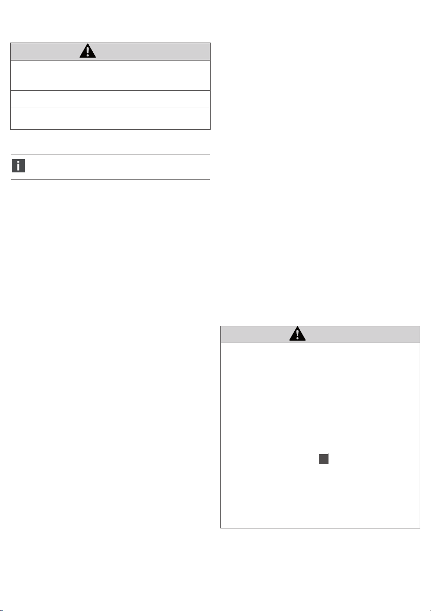
Grundplatten zur Montage eines Druckregelventils
Base plates for assembling a pressure regulator
Embases pour montage d’un régulateur de pression
Piastre base per il montaggio di una valvola riduttrice di pressione
Placas base para montaje de una válvula reguladora de presión
Basplattor för montering av en tryckregulator
ED07
R414006606/10.2014, Replaces: 04.2012, DE/EN/FR/IT/ES/SV
Page 2

AVENTICS | ED07 | R414006606–BDL–001–AB | Deutsch 1
Deutsch
1 Zu dieser Dokumentation
Gültigkeit der Dokumentation
Diese Dokumentation gilt für folgende Grundplatten:
W Einzelanschlussplatte, Serie ED07, (5610211052),
nach ISO 15407-1, 26 mm Baubreite, zur senkrechten
Befestigung an einer Montagefläche
W Einzelanschlussplatte, Serie ED07, (5610231002) zur
seitlichen Befestigung an einer Montagefläche
W Verkettungsplatte, Serie ED07 (8985049932), nach
ISO 5599-1, Größe 1, zur Verkettung mehrerer
Komponenten
Diese Dokumentation richtet sich an Monteure.
Erforderliche und ergänzende
Dokumentationen
O Nehmen Sie das Produkt erst in Betrieb, wenn Ihnen
die folgende Dokumentationen vorliegen und Sie diese
verstanden und beachtet haben.
Titel Dokumentnummer Dokumentart
ED07Druckregelventil
Anlagen-dokumentation
Falls das Produkt in sicherheitsgerichteten Steuerungen
eingesetzt wird, beachten Sie die Herstellerinformation
TC 40501-010 „Zuverlässigkeitskennwerte und weitere
Angaben zur Anwendung der EN ISO 13849-1“ von
AVENTICS.
Darstellung von Informationen
Sicherheitshinweise
In dieser Dokumentation stehen Sicherheitshinweise vor
einer Handlungsabfolge, bei der die Gefahr von Personenoder Sachschäden besteht. Die beschriebenen
Maßnahmen zur Gefahrenabwehr müssen eingehalten
werden.
Sicherheitshinweise sind wie folgt aufgebaut:
Art und Quelle der Gefahr
Folgen bei Nichtbeachtung
O Maßnahme zur Gefahrenabwehr
R414001671 Betriebs-
anleitung
SIGNALWORT
VORSICHT
Kennzeichnet eine gefährliche Situation, in der leichte
bis mittelschwere Körperverletzungen eintreten
können, wenn sie nicht vermieden wird.
ACHTUNG
Sachschäden: Das Produkt oder die Umgebung können
beschädigt werden.
Symbole
Wenn diese Information nicht beachtet wird, kann
das Produkt nicht optimal genutzt bzw. betrieben
werden.
2 Sicherheitshinweise
Zu diesem Kapitel
Das Produkt wurde gemäß den allgemein anerkannten
Regeln der Technik hergestellt. Trotzdem besteht die
Gefahr von Personen- und Sachschäden, wenn Sie dieses
Kapitel und die Sicherheitshinweise in dieser
Dokumentation nicht beachten.
O Lesen Sie diese Dokumentation gründlich und
vollständig, bevor Sie mit dem Produkt arbeiten.
O Bewahren Sie die Dokumentation so auf, dass sie
jederzeit für alle Benutzer zugänglich ist.
O Geben Sie das Produkt an Dritte stets zusammen mit
den erforderlichen Dokumentationen weiter.
Bestimmungsgemäße Verwendung
Das Produkt ist eine pneumatische Anlagenkomponente.
Es darf ausschließlich an ein Druckregelventil der
Serie ED07 montiert werden.
Das Produkt ist für den professionellen Gebrauch und
nicht für die private Verwendung bestimmt.
Das Produkt darf in sicherheitsgerichteten
Steuerungsketten verwendet werden, wenn die
Gesamtanlage darauf ausgerichtet ist.
Nicht bestimmungsgemäße Verwendung
Jeder andere Gebrauch als in der bestimmungsgemäßen
Verwendung beschrieben ist nicht bestimmungsgemäß
und deshalb unzulässig.
Für Schäden bei nicht bestimmungsgemäßer
Verwendung übernimmt die AVENTICS GmbH keine
Haftung. Die Risiken bei nicht bestimmungsgemäßer
Verwendung liegen allein beim Benutzer.
Zur nicht bestimmungsgemäßen Verwendung des
Produkts gehört der Einsatz der Grundplatte in
sicherheitsrelevanten Steuerungen.
Page 3
AVENTICS | ED07 | R414006606–BDL–001–AB | Deutsch 2
Qualifikation des Personals
Die in dieser Dokumentation beschriebenen Tätigkeiten
erfordern grundlegende Kenntnisse der Mechanik und
Pneumatik sowie Kenntnisse der zugehörigen Fachbegriffe.
Um die sichere Verwendung zu gewährleisten, dürfen diese
Tätigkeiten daher nur von einer entsprechenden Fachkraft
oder einer unterwiesenen Person unter Leitung einer
Fachkraft durchgeführt werden.
Eine Fachkraft ist, wer aufgrund seiner fachlichen
Ausbildung, seiner Kenntnisse und Erfahrungen sowie
seiner Kenntnisse der einschlägigen Bestimmungen die
ihm übertragenen Arbeiten beurteilen, mögliche Gefahren
erkennen und geeignete Sicherheitsmaßnahmen treffen
kann. Eine Fachkraft muss die einschlägigen
fachspezifischen Regeln einhalten.
Allgemeine Sicherheitshinweise
W Beachten Sie die gültigen Vorschriften zur
Unfallverhütung und zum Umweltschutz.
W Beachten Sie die Sicherheitsvorschriften und
-bestimmungen des Landes, in dem das Produkt
eingesetzt/angewendet wird.
W Verwenden Sie AVENTICS-Produkte nur in technisch
einwandfreiem Zustand.
W Personen, die AVENTICS-Produkte montieren,
bedienen, demontieren oder warten, dürfen nicht unter
dem Einfluss von Alkohol, sonstigen Drogen oder
Medikamenten, die die Reaktionsfähigkeit
beeinflussen, stehen.
W Verwenden Sie nur vom Hersteller zugelassene
Zubehör- und Ersatzteile, um Personengefährdungen
wegen nicht geeigneter Ersatzteile auszuschließen.
W Halten Sie die in der Produktdokumentation
angegebenen technischen Daten und
Umgebungsbedingungen ein.
W Sie dürfen das Produkt erst dann in Betrieb nehmen,
wenn festgestellt wurde, dass das Endprodukt
(beispielsweise eine Maschine oder Anlage), in das die
AVENTICS-Produkte eingebaut sind, den
länderspezifischen Bestimmungen,
Sicherheitsvorschriften und Normen der Anwendung
entspricht.
Produkt- und technologieabhängige
Sicherheitshinweise
VORSICHT
Beschädigung der Dichtungen!
Die Einzelanschlussplatte zur seitlichen Befestigung
(5610231002) und die Verkettungsplatte (8985049932)
dürfen maximal für Druckbereiche bis 12 bar
verwendet werden.
O Verwenden Sie für ED07-Druckregelventile mit dem
Druckbereich 16/20 bar ausschließlich die
Einzelanschlussplatte zur senkrechten Befestigung
5610211052.
VORSICHT
Gefahr durch austretende Druckluft an der
Einzelanschlussplatte!
Die Grundplatte steht im Betrieb unter Druck. Beim
Öffnen des zusätzlichen Eingangsanschlusses ( – 1)
an der Einzelanschlussplatte 5610211052 kann die
Verschlussschraube durch austretende Druckluft in die
Umgebung geschleudert werden und Personen- und
Sachschäden verursachen.
O Öffnen Sie niemals die Verschlussschraube im
Betrieb.
O Schließen Sie einen zusätzlichen Eingangsanschluss
nur im drucklosen Zustand an.
1
3 Allgemeine Hinweise zu
Sachschäden und
Produktschäden
ACHTUNG
Unsachgemäß montierte Dichtungen!
Druckverlust im Betrieb.
O Stellen Sie vor der Inbetriebnahme sicher, dass die
Dichtung zwischen Druckregelventil und
Grundplatte korrekt montiert ist.
Mechanische Belastungen!
Beschädigung der Grundplattenbefestigung!
O Sie dürfen die Grundplatten nicht unter
mechanischer Spannung befestigen.
O Vermeiden Sie beim Anschließen der Schläuche
mechanische Spannungen.
4 Lieferumfang
Im Lieferumfang sind enthalten:
W 1 Grundplatte, Serie ED07 (entweder
1 Einzelanschlussplatte zur senkrechten Befestigung
5610211052 oder 1 Einzelanschlussplatte zur
seitlichen Befestigung 5610231002 oder
1 Verkettungsplatte 8985049932)
W 1 Montageanleitung
Der Lieferumfang der Verkettungsplatte 8985049932
enthält zusätzlich zur Verkettung:
W 2 Schrauben M5x20
W 2 Unterlegscheiben
W 2 Muttern M5
W 3 O-Ringe
Page 4

AVENTICS | ED07 | R414006606–BDL–001–AB | Deutsch 3
5 Zu diesem Produkt
Die Grundplatten unterscheiden sich wie folgt:
W Einzelanschlussplatte, Serie ED07, (5610211052),
nach ISO 15407-1, 26 mm Baubreite, zur senkrechten
Befestigung an einer Montagefläche
W Einzelanschlussplatte, Serie ED07, (5610231002) zur
seitlichen Befestigung an einer Montagefläche,
W Verkettungsplatte, Serie ED07 (8985049932), nach
ISO 5599-1, Größe 1, zur Verkettung mehrerer
Komponenten.
Identifikation des Produkts
O Überprüfen Sie anhand der Materialnummer, die auf
dem Gehäuse aufgedruckt ist, ob die Grundplatte mit
Ihrer Bestellung übereinstimmt.
6 Montage
ACHTUNG
Offene Pneumatikanschlüsse!
Verschmutzung der angeschlossenen Ventile!
O Stellen Sie z. B. durch Verschlussstopfen sicher,
dass kein Schmutz in die Grundplatte eindringen
kann. Öffnen Sie die Anschlüsse erst unmittelbar,
bevor Sie die Verschlauchung anschließen.
Einbaubedingungen
Die Grundplatte darf mit geölter und ungeölter Druckluft
betrieben werden.
O Lassen Sie die Grundplatte und das ED07-
Druckregelventil vor dem Einbau einige Stunden
akklimatisieren, da sich ansonsten in der Grundplatte
Kondenswasser niederschlagen kann.
Einbaulage
Die Einbaulage der Grundplatte ist beliebig.
O Beachten Sie die Einbaulage des Druckregelventils.
Grundplatte montieren
Die Grundplatte ist in verschiedenen Ausführungen als
Zubehörteil erhältlich. In den Abbildung – sind alle
Grundplatten in der richtigen Montageposition dargestellt.
Je nach Ausführung unterscheidet sich die Reihenfolge
der Montageschritte.
7 9
2
Verkettungsplatten verketten
Zur Verkettung der Verkettungsplatten benötigen Sie die
in „4 Lieferumfang“ aufgeführten Teile.
1. Setzen Sie die drei O-Ringe auf die pneumatischen
Anschlüsse auf.
2. Setzen Sie die Unterlegscheiben auf die Schrauben
M5x20 auf und verschrauben Sie die
Verkettungsplatten mit den Muttern M5.
Anzugsmoment: 6 Nm
3 4
Grundplatte an der Montagefläche
befestigen
Bei Einzelanschlussplatten zur seitlichen
Befestigung und Verkettungsplatten können Sie
diesen Schritt auch durchführen, nachdem Sie das
Druckregelventil auf der Grundplatte montiert
haben.
O Schalten Sie den relevanten Anlagenteil spannungsfrei
und drucklos, bevor Sie die Grundplatte an der
Montagefläche befestigen. Entlüften Sie dabei die
Anlage langsam, um unkontrollierte Bewegungen zu
vermeiden.
Die Grundplatten werden je nach Bauart auf verschiedene
Arten an der Montagefläche befestigt.
W Einzelanschlussplatte 5610211052:
Über zwei Durchgangsbohrungen auf der Oberseite
der Grundplatte .
Benötigtes Befestigungsmaterial:
– 2 Schrauben M6x40,
Anzugsmoment: 8 Nm bei Schraubengüte 8.8
– 2 Unterlegscheiben
W Einzelanschlussplatte 5610231002:
Über zwei Durchgangsbohrungen seitlich an der
Grundplatte .
Benötigtes Befestigungsmaterial:
– 2 Schrauben M8x60,
Anzugsmoment: 23 Nm bei Schraubengüte 8.8
– 2 Unterlegscheiben
W Verkettungsplatte 8985049932:
Die verketteten Verkettungsplatten werden über die
Endplatte links und die Endplatte rechts an der
Montagefläche befestigt. Benötigtes
Befestigungsmaterial: je nach Endplatte
Zur Befestigung der Grundplatten an der
Montagefläche müssen Sie eigenes
Befestigungsmaterial verwenden. Hierfür gelten
die allgemeinen Regeln der Technik.
3
4
O Entnehmen Sie die genauen Abmessungen der
Befestigungen für Ihre Grundplatte dem Online-Katalog
von AVENTICS (www.aventics.com/pneumatics-catalog)
O Bauen Sie die Grundplatte so in Ihren Anlagenteil ein,
dass Sie die pneumatischen Anschlüsse immer
erreichen können.
Page 5
AVENTICS | ED07 | R414006606–BDL–001–AB | Deutsch 4
O Befestigen Sie die Grundplatte so an der
Montagefläche, dass sie nicht unter Spannung steht.
Beachten Sie dabei die maximal zulässigen
Anzugsmomente der Befestigungsschrauben.
5
Grundplattendichtung im Druckregelventil
einlegen
1. Legen Sie die Grundplattendichtung ( – 2) auf die
Unterseite des ED07-Druckregelventils, so dass die
drei Pneumatiköffnungen nicht verdeckt sind.
2. Drücken Sie die Grundplattendichtung leicht an, so
dass sie auf den drei Fixierstiften ( – 3) im
Druckregelventil steckt.
Die drei Fixierstifte stellen sicher, dass die
Grundplattendichtung korrekt auf der Kontur der
Pneumatiköffnungen sitzt.
6
Druckregelventil auf die Grundplatte
5
5
aufsetzen
Auf der Grundplatte befindet sich ein Kodierstift ( – 5),
der in die dazugehörige Kodierbohrung ( – 4) des ED07Druckregelventils passt. Die korrekte Montage ist dadurch
sichergestellt.
Die Verkettungsplatte hat zwei Kodierstifte. Am
ED07-Druckregelventil befindet sich daher eine
zweite Kodierbohrung auf derselben Seite. Eine
Verwechslung ist ausgeschlossen.
1. Drehen Sie das ED07-Druckregelventil so, dass der
Kodierstift ( – 5) und die Kodierbohrung ( – 4)
sich auf derselben Seite befinden und ineinander
greifen können.
2. Setzen Sie das ED07-Druckregelventil auf die
Grundplatte auf. Stellen Sie dabei sicher, dass sich die
Grundplattendichtung nicht verschiebt.
Der Kodierstift der Grundplatte greift in die
Kodierbohrung des ED07-Druckregelventils.
7 9
6 6
Druckregelventil an der Grundplatte
6
6
festschrauben
ACHTUNG
Falsche Befestigung der Ventile!
Beschädigung der Ventile!
O Beachten Sie die maximalen Anzugsmomente und
überprüfen Sie den festen Sitz aller Schrauben.
2. Kontrollieren Sie nochmals den einwandfreien Sitz der
Grundplattendichtung, um die Schutzklasse IP 65 zu
gewährleisten.
Die Grundplattendichtung darf an der Seite nicht
überstehen.
Grundplatte pneumatisch anschließen
O Entnehmen Sie die Hinweise zum Anschluss der
Pneumatik der Anleitung des ED07-Druckregelventils
R414001671.
Im Online-Katalog finden Sie pneumatische
Verbindungstechnik zur Verschlauchung der
Grundplatte.
7 Demontage und Entsorgung
Grundplatte demontieren
VORSICHT
Verbrennungsgefahr durch heiße Oberflächen!
Berühren der Oberflächen der Ventile im laufenden
Betrieb kann zu Verbrennungen führen.
O Lassen Sie die Ventile abkühlen, bevor Sie die
Grundplatte ausbauen.
O Berühren Sie die Ventile nicht im Betrieb.
1. Schalten Sie den relevanten Anlagenteil spannungsfrei
und drucklos. Entlüften Sie dabei die Anlage langsam,
um unkontrollierte Bewegungen zu vermeiden.
2. Entfernen Sie die pneumatischen Anschlüsse von der
Grundplatte.
3. Entfernen Sie das Druckregelventil und die
Grundplatte von der Montagefläche. Die Reihenfolge
richtet sich nach dem Grundplattentyp.
Grundplatte entsorgen
Achtloses Entsorgen der Grundplatte führt zu
Umweltverschmutzungen. Rohstoffe können dann nicht
mehr wiederverwertet werden.
O Entsorgen Sie die Grundplatte daher nach den
Bestimmungen Ihres Landes.
1. Setzen Sie die vier Schrauben M5x90 wie in der
Abbildung in die vier Durchgangsbohrungen des
Druckregelventils ein und schrauben Sie diese in die
Gewindebohrungen der Grundplatte.
Anzugsmoment: 6 Nm
Page 6

AVENTICS | ED07 | R414006606–BDL–001–AB | Deutsch/English 5
8 Technische Daten
Allgemeine Daten
Abmessungen 5610211052:
Gewicht 5610211052: 475 g
Thermischer
Anwendungsbereich
Einbaulage beliebig
Betriebsdruck
min./max
zulässiges Medium Druckluft
Werkstoff Aluminium
54 mm x 97 mm x 40 mm
5610231002:
48 mm x 135,2 mm x 39 mm
8985049932:
43 mm x 110 mm x 67 mm
5610231002: 277 g
8985049932: 453 g
siehe Druckregelventil
5610211052: 0 bis 20 bar
5610231002: 0 bis 12 bar
8985049932: 0 bis 12 bar
9 Zubehör
English
1 About This Documentation
Documentation validity
This documentation applies to the following base plates:
W Single subbase, ED07 series, (5610211052), acc. to
ISO 15407-1, 26 mm width, for vertical fastening to a
mounting surface
W Single subbase, ED07 series, (5610231002) for
fastening to the side of a mounting surface
W Sandwich base, ED07 series (8985049932), acc. to
ISO 5599-1, size 1, for linking several components
This documentation is intended for installers.
Required and supplementary
documentation
O Only commission the product once you have obtained
the following documentation and understood and
complied with its contents.
Title
ED07 Pressure Regulator R414001671 Operating
System documentation
Document
number
Document
type
instructions
Titel Materialnummer
Schalldämpfer, Serie SI1, Ø G3/8 1827000002
Im Online-Katalog finden Sie pneumatische
Verbindungstechnik zur Verschlauchung der
Grundplatte.
If the product is used in safety-related controls, please
note the information from AVENTICS TC 40501-010
“Reliability characteristics and other EN ISO 13849-1
information”.
Presentation of information
Safety instructions
In this document, there are safety instructions preceding
the steps whenever there is a danger of personal injury or
damage to the equipment. The measures described to
avoid these hazards must be observed.
Safety instructions are set out as follows:
SIGNAL WORD
Type and source of risk
Consequences
O Precautions
Page 7
AVENTICS | ED07 | R414006606–BDL–001–AB | English 6
CAUTION
Indicates a potentially hazardous situation which, if not
avoided, could result in minor or moderate injury or
damage to equipment.
NOTICE
Indicates damage: the product or the environment may
be damaged.
Symbols
If this information is disregarded, the product
cannot be used or operated optimally.
2 Notes on Safety
About this chapter
The product has been manufactured according to the
accepted rules of current technology. Even so, there is risk
of injury and damage to equipment if the following chapter
and safety instructions of this documentation are not
followed.
O Read these instructions completely before working
with the product.
O Keep this documentation in a location where it is
accessible to all users at all times.
O Always include the documentation when you pass the
product on to third parties.
Intended use
The product is a pneumatic system component. It may
only be assembled to an ED07 series pressure regulator.
The product is intended for professional use only.
The product may be used in safety-related control chains
if the entire system is geared toward this purpose.
Improper use
Any use other than that described under Intended use is
improper and is not permitted.
AVENTICS GmbH is not liable for any damages resulting
from improper use. The user alone bears the risks of
improper use of the product.
It is considered improper use of the product when the base
plate is used in safety-relevant controls.
Personnel qualifications
The work described in this documentation requires basic
mechanical and pneumatic knowledge, as well as
knowledge of the appropriate technical terms. In order to
ensure safe use, these activities may therefore only be
carried out by qualified technical personnel or an
instructed person under the direction and supervision of
qualified personnel.
Qualified personnel are those who can recognize possible
hazards and institute the appropriate safety measures, due
to their professional training, knowledge, and experience,
as well as their understanding of the relevant conditions
pertaining to the work to be done. Qualified personnel must
observe the rules relevant to the subject area.
General safety instructions
W Observe the regulations for accident prevention and
environmental protection.
W Observe the safety instructions and regulations
applicable in the country in which the product is used.
W Only use AVENTICS products that are in perfect
working order.
W Persons assembling, operating, disassembling, or
maintaining AVENTICS products may not be under the
influence of alcohol, other drugs, or medications that
influence their ability to respond.
W To avoid injuries due to unsuitable spare parts, only
use accessories and spare parts approved by the
manufacturer.
W Comply with the technical data and ambient conditions
listed in the product documentation.
W You may only commission the product if you have
determined that the end product (such as a machine or
system) in which the AVENTICS products are installed,
meet the country-specific provisions, safety
regulations, and standards for the specific application.
Safety instructions related to the product
and technology
CAUTION
Damage to seals!
The single subbase for fastening to the side
(5610231002) and the sandwich base (8985049932)
may only be used at a maximum pressure of 12 bar.
O Only use single subbases for vertical fastening
(5610211052) with ED07 pressure regulators with a
pressure of 16/20 bar.
Danger caused by compressed air escaping from the
single subbase!
The base plate is under pressure during operation. If the
additional inlet connection ( – 1) on the single
subbase (5610211052) is opened, the blanking screw
may be forced out by the compressed air and cause
injuries or damage.
O Never open the blanking screw during operation.
O Only connect additional inlet connections when the
system is in a pressure-free state.
1
Page 8

AVENTICS | ED07 | R414006606–BDL–001–AB | English 7
3 General Instructions on
Equipment and Product
Damage
NOTICE
Improperly assembled seals!
Loss of pressure during operation.
O Before commissioning, make sure that the seal
between the pressure regulator and base plate is
correctly assembled.
Mechanical loads!
Damage to the base plate fastening!
O Do not fasten the base plate under mechanical
loads.
O Avoid mechanical loads when connecting the tubing.
4 Delivery contents
The delivery contents include:
W 1 base plate, ED07 series (either 1 single subbase for
vertical fastening 5610211052 or 1 single subbase for
side fastening 5610231002 or 1 sandwich base
8985049932)
W 1 set of assembly instructions
The delivery contents for the sandwich base (8985049932)
also include the following for linking:
W 2 M5x20 screws
W 2 washers
W 2 M5 nuts
W 3 O-rings
5 About This Product
The base plates differ as follows:
W Single subbase, ED07 series, (5610211052), acc. to
ISO 15407-1, 26 mm width, for vertical fastening to a
mounting surface
W Single subbase, ED07 series, (5610231002) for
fastening to the side of a mounting surface
W Sandwich base, ED07 series (8985049932), acc. to
ISO 5599-1, size 1, for linking several components.
Product identification
O Check that the base plate matches your order using the
material number printed on the housing.
6 Assembly
NOTICE
Open pneumatic connections!
Contamination of connected valves!
O Make sure that no contamination can penetrate the
base plate e.g. by using blanking plugs. Only open
the connections just before connecting the tubing.
Installation requirements
The base plate may be operated with oiled and non-oiled
compressed air.
O Let the base plate and ED07 pressure regulator
acclimate itself for several hours before installation,
otherwise water may condense in the base plate.
Mounting orientation
Any mounting orientation may be used for the base plate.
O Note the mounting orientation of the pressure
regulator.
Mounting the base plate
The base plate is available in various designs as an
accessory part. All of the base plates are shown in the
correct mounting orientations in figure –
The order of assembly steps varies according to the
version.
2
Linking sandwich bases
The parts listed in “4 Delivery contents” are required to
link the sandwich bases.
1. Place the three O-rings on the pneumatic connections.
2. Place the washers on the M5x20 screws and tighten
the sandwich bases with the M5 nuts.
Tightening torque: 6 Nm
3 4
Fastening base plates to the mounting
surface
With single subbases for side fastening and
sandwich subbases, this step can also be done
after you have assembled the pressure regulator
on the base plate.
O Make sure the relevant system part is not under
voltage or pressure before fastening the base plate to
the mounting surface. Slowly exhaust the system to
avoid uncontrolled movements.
The base plates are fastened to the assembly surface in
various manners, depending on the type.
7 9
.
Page 9
AVENTICS | ED07 | R414006606–BDL–001–AB | English 8
W Single subbase 5610211052:
to the top side of the base plate using two through
3
holes .
Required mounting material:
– 2 M6x40 screws,
tightening torque 8 Nm with bolt grade 8.8
– 2 washers
W Single subbase (5610231002): to the side of the base
plate using two through holes .
Required mounting material:
– 2 M8x60 screws,
tightening torque: 23 Nm with bolt grade 8.8
– 2 washers
W Sandwich base 8985049932:
The linked sandwich bases are fastened to the
assembly surface using the left and right end plates.
Required mounting material: depends on end plate
Suitable own mounting material must be used in
order to fasten the base plates to the assembly
surface. The general rules of technology apply
here.
O You can find the exact dimensions of the mountings for
your base plate in the online catalog from AVENTICS
(
www.aventics.com/pneumatics-catalog)
O Install the base plate in your system in a manner where
the pneumatic connections are always accessible.
O Fasten the base plate to the assembly surface so that
it is not under any stress. While doing so, observe the
maximum permissible tightening torque values for the
mounting screws.
5
Inserting the base plate seal in the pressure
4
.
regulator
1. Place the base plate seal ( – 2) on the lower side of
the ED07 pressure regulator so that the three
pneumatic ports are not covered.
2. Gently press down on the base plate seal so it is fixed
on the three mounting pins ( – 3) in the pressure
regulator.
The three mounting pins ensure that the base plate
seal is placed correctly on the contour of the
pneumatic ports.
6
Placing the pressure regulator on a base plate
A coded pin ( – 5) is located on the base plate, which fits
in the coded hole ( – 4) of the ED07 pressure regulator.
This ensures correct assembly.
1. Turn the ED07 pressure regulator so that the coded pin
( – 5) and coded hole ( – 4) are on the same side
and the pin can be inserted into the hole.
6
6
The sandwich base has two coded pins. This is
why there is a second coded hole on the same side
of the ED07 pressure regulator. Mix-ups are ruled
out by this.
6 6
5
5
2. Place the ED07 pressure regulator on the base plate.
Make sure that the base plate seal does not slide out of
place.
The coded pin on the base plate will fit into the coded
hole in the ED07 pressure regulator.
7 9
Screwing the pressure regulator onto the
base plate
NOTICE
Incorrect valve mounting!
Valves may be damaged!
O Observe the maximum tightening torque values and
check that all screws and bolts are properly
tightened.
1. Insert the four M5x90 screws in the four through holes
of the pressure regulator as shown in the figure and
screw them into the threaded holes of the base plate.
Tightening torque: 6 Nm
2. Check again that the base plate seal is fitted properly
to ensure the IP 65 protection class.
The base plate seal may not protrude on the sides.
Connecting the base plate pneumatics
O For information on how to connect the pneumatics,
please see the instructions for the ED07 pressure
regulator R414001671.
You can find the pneumatic connection technology
for base plate tubing in the online catalog.
7 Disassembly and Disposal
Disassembling the base plate
CAUTION
Danger of burns caused by hot surfaces!
Touching the surfaces of the valves during operation
could lead to burns.
O Let the valves cool off before disassembling the
base plate.
O Do not touch the valves during operation
1. Make sure the relevant system part is not under
voltage or pressure. Slowly exhaust the system to
avoid uncontrolled movements.
2. Remove the pneumatic connections from the base
plate.
3. Remove the pressure regulator and base plate from
the assembly surface. The disassembly order depends
on the type of base plate.
Page 10

AVENTICS | ED07 | R414006606–BDL–001–AB | English/Français 9
Disposing of the base plate
Careless disposal of the base plate will lead to pollution of
the environment. Furthermore, the materials can no
longer be recycled.
O Dispose of the base plate in accordance with your
country’s national regulations.
8 Technical Data
General data
Dimensions 5610211052:
Weight 5610211052: 475 g
Temperature range See pressure regulator
Mounting orientation Any
Working pressure
min./max.
Permissible medium Compressed air
Material Aluminum
54 mm x 97 mm x 40 mm
5610231002:
48 mm x 135.2 mm x 39 mm
8985049932:
43 mm x 110 mm x 67 mm
5610231002: 277 g
8985049932: 453 g
5610211052: 0 to 20 bar
5610231002: 0 to 12 bar
8985049932: 0 to 12 bar
Français
1 A propos de cette
documentation
Validité de la documentation
La présente documentation est valable pour les embases
suivantes :
W Embase unitaire, série ED07, (5610211052),
selon ISO 15407-1, largeur 26 mm, pour fixation
verticale à une surface de montage
W Embase unitaire, série ED07 (5610231002), pour
fixation latérale à une surface de montage
W Embase modulaire, série ED07 (8985049932),
selon ISO 5599-1, taille 1, pour combinaison de
plusieurs composants
Cette documentation a été conçue à l’usage des monteurs.
Documentations nécessaires et
complémentaires
O Ne mettre le produit en service qu’en possession des
documentations suivantes et qu’après les avoir
comprises et observées.
Titre
Régulateur de pression
ED07
Documentation de l’installation
N° de
document
R414001671 Mode
Type de
document
d’emploi
9 Accessories
Title Material number
Silencer, SI1 series, Ø G3/8 1827000002
You can find the pneumatic connection technology
for base plate tubing in the online catalog.
Si le produit est utilisé dans des commandes destinées à
la sécurité, observer la note d’information TC 40501-010
intitulée « Cotes de fiabilité et autres indications pour
l’application de la norme EN ISO 13849-1 » de AVENTICS.
Présentation des informations
Consignes de sécurité
Dans la présente documentation, des consignes de
sécurité figurent devant les instructions dont l’exécution
recèle un risque de dommages corporels ou matériels.
Les mesures décrites pour éviter des dangers doivent être
respectées.
Les consignes de sécurité sont structurées comme suit :
MOT-CLE
Type et source de danger
Conséquence en cas de non-respect
O Mesures préventives contre les dangers
Page 11

AVENTICS | ED07 | R414006606–BDL–001–AB | Français 10
ATTENTION
Signale une situation dangereuse susceptible d’entraîner
des blessures légères à modérées si le danger n’est pas
évité.
REMARQUE
Dommages matériels : le produit ou son environnement
peuvent être endommagés.
Symboles
En cas de non respect de cette information, le
produit ne livrera pas sa performance optimale.
2 Consignes de sécurité
A propos de ce chapitre
Le produit a été fabriqué selon les règles techniques
généralement reconnues. Des dommages matériels et
corporels peuvent néanmoins survenir si ce chapitre de
même que les consignes de sécurité ne sont pas
respectés.
O Lire la présente documentation attentivement et
complètement avant d’utiliser le produit.
O Conserver cette documentation de sorte que tous les
utilisateurs puissent y accéder à tout moment.
O Toujours transmettre le produit à de tierces personnes
accompagné des documentations nécessaires.
Utilisation conforme
Ce produit est un composant d’installation pneumatique et
doit exclusivement être monté sur un régulateur de
pression de série ED07.
Le produit est destiné à un usage dans le domaine
professionnel et non privé.
Le produit ne doit être utilisé dans des chaînes de
commande destinées à la sécurité que si l’installation
complète est conçue à cet effet.
Utilisation non conforme
Toute autre utilisation que celle décrite au chapitre
« Utilisation conforme » est non conforme et par
conséquent interdite.
La société AVENTICS GmbH décline toute responsabilité
en cas de dommages résultant d’une utilisation non
conforme. Toute utilisation non conforme est aux risques
et périls de l’utilisateur.
Compte parmi les utilisations non conformes du produit
l’utilisation de l’embase dans des commandes
importantes pour la sécurité.
Qualification du personnel
Les opérations décrites dans cette documentation exigent
des connaissances mécaniques et pneumatiques de base,
ainsi que la connaissance des termes techniques qui y
sont liés. Afin d’assurer une utilisation en toute sécurité,
ces travaux ne doivent par conséquent être effectués que
par des professionnels spécialement formés ou par une
personne instruite et sous la direction d’un spécialiste.
Une personne spécialisée est capable de juger des travaux
qui lui sont confiés, de reconnaître d’éventuels dangers et
de prendre les mesures de sécurité adéquates grâce à sa
formation spécialisée, ses connaissances et expériences,
ainsi qu’à ses connaissances des directives correspondantes.
Elle doit respecter les règles spécifiques
correspondantes.
Consignes générales de sécurité
W Respecter les consignes de prévention d’accidents et
de protection de l’environnement applicables.
W Respectez les dispositions et prescriptions de sécurité
du pays d’utilisation / d’application.
W Utiliser les produits AVENTICS exclusivement lorsque
leur état technique est irréprochable.
W Les personnes montant, commandant, démontant ou
entretenant des produits AVENTICS, ne doivent pas
être sous l’emprise d’alcool, de drogues ou de
médicaments divers pouvant altérer leur temps de
réaction.
W Utiliser exclusivement les accessoires et pièces de
rechange agréés par le constructeur afin de ne pas
mettre en danger les personnes du fait de pièces de
rechange non appropriées.
W Respecter les données techniques ainsi que les
conditions ambiantes spécifiées dans la
documentation du produit.
W Il n’est admis de mettre le produit en service que
lorsqu’il a été constaté que le produit final
(par exemple une machine ou une installation) dans
lequel les produits AVENTICS sont employés satisfait
bien aux dispositions du pays d’utilisation,
prescriptions de sécurité et normes de l’application.
Consignes de sécurité selon le produit et
la technique
ATTENTION
Endommagement des joints !
L’embase unitaire pour fixation latérale (5610231002)
ainsi que l’embase modulaire (8985049932) ne doivent
être utilisées que pour une plage de pression de max.
12 bar.
O Pour les régulateurs de pression ED07 avec plage de
pression de 16 à 20 bar, utiliser exclusivement
l’embase unitaire pour fixation
verticale 5610211052.
Page 12

AVENTICS | ED07 | R414006606–BDL–001–AB | Français 11
ATTENTION
Danger dû à de l’air comprimé s’échappant de
l’embase unitaire !
Lors du fonctionnement, l’embase est sous pression. En
ouvrant le raccord d’entrée supplémentaire ( – 1) de
l’embase unitaire 5610211052, le bouchon à visser peut
être éjecté par l’échappement d’air comprimé et
occasionner des dommages corporels et matériels.
O Lors du fonctionnement, ne jamais ouvrir le bouchon
à visser.
O Ne raccorder tout raccord d’entrée supplémentaire
qu’à l’état hors pression.
1
3 Consignes générales
sur les dégâts matériels
et les endommagements
du produit
REMARQUE
Montage non conforme des joints !
Perte de pression lors du fonctionnement.
O Avant la mise en service, s’assurer que le joint situé
entre le régulateur de pression et l’embase est
correctement monté.
Contraintes mécaniques !
Endommagement de la fixation de l’embase !
O Il est interdit de fixer les embases sous contrainte
mécanique.
O Lors du raccordement des flexibles, éviter toute
contrainte mécanique.
4 Fourniture
Sont compris dans la fourniture :
W 1 embase, série ED07 (soit 1 embase unitaire pour
fixation verticale 5610211052 ou 1 embase unitaire
pour fixation latérale 5610231002 ou 1 embase
modulaire 8985049932)
W 1 mode d’emploi
Pour la combinaison, la fourniture de l’embase
modulaire 8985049932 contient en plus :
W 2 vis M5x20
W 2 rondelles
W 2 écrous M5
W 3 joints toriques
5 A propos de ce produit
Les embases se distinguent comme suit :
W Embase unitaire, série ED07, (5610211052),
selon ISO 15407-1, largeur 26 mm, pour fixation
verticale à une surface de montage
W Embase unitaire, série ED07 (5610231002), pour
fixation latérale à une surface de montage,
W Embase modulaire, série ED07 (8985049932),
selon ISO 5599-1, taille 1, pour combinaison de
plusieurs composants.
Identification du produit
O A l’aide du numéro de référence imprimé sur le boîtier,
vérifier que l’embase correspond bien à la commande
passée.
6 Montage
REMARQUE
Raccords pneumatiques ouverts !
Encrassement des distributeurs raccordés !
O A l’aide de bouchons d’obturation par exemple,
s’assurer qu’aucune saleté ne peut pénétrer dans
l’embase. N’ouvrir les raccords qu’immédiatement
avant le raccordement du flexible.
Conditions de montage
Le fonctionnement de l’embase est autorisé avec de l’air
comprimé lubrifié et non lubrifié.
O Avant le montage, laisser l’embase et le régulateur de
pression ED07 s’acclimater pendant quelques heures,
de l’eau de condensation pouvant sinon se créer dans
l’embase.
Position de montage
La position de montage de l’embase est indifférente.
O Observer la position de montage du régulateur de
pression.
Montage de l’embase
L’embase est disponible comme accessoire en différents
modèles. Les Fig. –
dans la position de montage correcte.
L’ordre des étapes de montage varie en fonction de la
version.
7 9
illustrent toutes les embases
Page 13

AVENTICS | ED07 | R414006606–BDL–001–AB | Français 12
2
Combinaison d’embases modulaires
Pour combiner les embases modulaires, les pièces
énumérées au chapitre 4 « Fourniture » sont nécessaires.
1. Placer les trois joints toriques sur les raccords
pneumatiques.
2. Placer les rondelles sur les vis M5x20 puis visser les
embases modulaires aux écrous M5.
Couple de serrage : 6 Nm
3 4
Fixation de l’embase à la surface de
montage
En cas d’embases unitaires pour fixation latérale
et d’embases modulaires, cette étape peut
également être effectuée après avoir monté le
régulateur de pression sur l’embase.
O Avant de fixer l’embase à la surface de montage,
mettre la partie pertinente de l’installation hors
tension. Ce faisant, purger lentement l’installation, afin
d’éviter tout mouvement incontrôlé.
En fonction du type de construction, les embases sont
fixées de différentes manières à la surface de montage.
W Embase unitaire 5610211052 : par deux trous lisses
sur la face supérieure de l’embase .
Accessoires de fixation requis :
– 2 vis M6x40,
couple de serrage : 8 Nm pour vis de classe 8.8
– 2 rondelles
W Embase unitaire 5610231002 : par deux trous lisses
sur le côté de l’embase .
Accessoires de fixation requis :
– 2 vis M8x60,
couple de serrage : 23 Nm pour vis de classe 8.8
– 2 rondelles
W Embase modulaire 8985049932 : les embases
modulaires combinées sont fixées à la surface de
montage par l’embase gauche et l’embase droite.
Accessoires de fixation requis : selon l’embase
Pour fixer les embases à la surface de montage, les
accessoires de fixation doivent être fournis. Les
règles techniques généralement reconnues
s’appliquent.
O Pour les dimensions exactes des fixations de l’embase,
se reporter au catalogue en ligne de AVENTICS
(
www.aventics.com/pneumatics-catalog)
O Monter l’embase sur la partie correspondante de
l’installation de manière à toujours pouvoir atteindre
les raccords pneumatiques.
O Fixer l’embase à la surface de montage de sorte que
l’embase ne soit pas sous tension. Respecter ce faisant
les couples de serrage maximaux admissibles des vis
de fixation.
4
3
.
5
Insertion du joint d’embase dans le
régulateur de pression
1. Insérer le joint d’embase ( – 2) sur la face inférieure
du régulateur de pression ED07, de sorte à ne pas
obstruer les trois orifices pneumatiques.
2. Enfoncer légèrement le joint d’embase, de sorte qu’il
se fixe sur les trois goupilles d’ajustage (
régulateur de pression.
Les trois goupilles d’ajustage assurent un
positionnement correct du joint d’embase sur le
contour des orifices pneumatiques.
6
Pose du régulateur de pression sur l’embase
La goupille de codage ( – 5) se trouvant sur l’embase
s’adapte dans l’orifice de codage correspondant ( – 4)
du régulateur de pression ED07. Un montage correct est
ainsi assuré.
L’embase modulaire dispose de deux goupilles de
codage. C’est pourquoi le régulateur de pression
ED07 possède un deuxième orifice de codage sur
la même face. Toute confusion est donc exclue.
1. Tourner le régulateur de pression ED07 de sorte que la
goupille de codage (
6
( - 4) se situent du même côté et qu’ils puissent
s’emboîter l’un dans l’autre.
2. Placer le régulateur de pression ED07 sur l’embase.
S’assurer ce faisant que le joint d’embase ne se
déplace pas.
La goupille de codage de l’embase s’emboîte dans
l’orifice de codage du régulateur de pression ED07.
7 9
Vissage à fond du régulateur de pression
5
5
6
6
– 5) et l’orifice de codage
– 3) du
6
sur l’embase
REMARQUE
Mauvaise fixation des distributeurs !
Endommagement des distributeurs !
O Respecter les couples maximaux et vérifier le
serrage ferme de toutes les vis.
1. Conformément à la figure, insérer les quatre vis M5x90
dans les quatre trous lisses du régulateur de pression,
puis serrer celles-ci dans les taraudages de l’embase.
Couple de serrage : 6 Nm
2. Contrôler de nouveau le positionnement irréprochable
du joint d’embase, afin de garantir l’indice de
protection IP 65.
Le joint d’embase ne doit pas dépasser sur le côté.
Page 14

AVENTICS | ED07 | R414006606–BDL–001–AB | Français 13
Raccordement pneumatique de l’embase
O Les consignes de raccordement du système
pneumatique figurent dans le mode
d’emploi R414001671 du régulateur de pression ED07.
Les techniques de liaison pneumatiques quant au
flexible de l’embase figurent dans le catalogue en
ligne.
7 Démontage et élimination
Démontage de l’embase
ATTENTION
Risque de brûlure dû à des surfaces chaudes !
Tout contact avec les surfaces de distributeurs en cours
de fonctionnement peut provoquer des brûlures.
O Laisser les distributeurs refroidir avant de démonter
l’embase.
O Ne pas toucher les distributeurs en cours de
fonctionnement.
1. Mettre la partie concernée de l’installation hors tension
et hors pression. Ce faisant, purger lentement
l’installation, afin d’éviter tout mouvement incontrôlé.
2. Retirer les branchements pneumatiques de l’embase.
3. Retirer le régulateur de pression ainsi que l’embase de
la surface de montage. L’ordre de procédure dépend
du type d’embase.
Elimination de l’embase
Une élimination négligente de l’embase peut nuire à
l’environnement. Dans ce cas, les matières premières ne
peuvent plus être recyclées.
O Eliminer l’embase selon les dispositions du pays
d’utilisation.
8 Données techniques
Données générales
Dimensions 5610211052 :
Poids 5610211052 : 475 g
Domaine d’application
thermique
Position de montage Indifférente
Pression de service
min. / max.
Fluide autorisé Air comprimé
Matériau Aluminium
54 mm x 97 mm x 40 mm
5610231002 :
48 mm x 135,2 mm x 39 mm
8985049932 :
43 mm x 110 mm x 67 mm
5610231002 : 277 g
8985049932 : 453 g
Voir régulateur de pression
5610211052 : 0 à 20 bar
5610231002 : 0 à 12 bar
8985049932 : 0 à 12 bar
9 Accessoires
Désignation
Silencieux, série SI1, Ø G3/8 1827000002
Les techniques de liaison pneumatiques quant au
flexible de l’embase figurent dans le catalogue en
ligne.
Numéro de
référence
Page 15

1
1
Zusätzlicher Eingangsanschluss (5610211052) /
Additional inlet connection (5610211052) /
Raccord d’entrée supplémentaire (5610211052)
2
Verkettungsplatte verketten /
Linking the sandwich base /
Combinaison d’embases modulaires
M5x20
6 Nm
M8x60, 8.8
4
Einzelanschlussplatte 5610231002 seitlich befestigen /
Fastening the single subbase 5610231002 on the side /
Fixation latérale de l’embase unitaire 5610231002
32
23 Nm
5
Grundplattendichtung am Druckregelventil einlegen /
Inserting the base plate seal in the pressure regulator /
Insertion du joint d’embase dans le régulateur de pression
M6x40, 8.8
8 Nm
Einzelanschlussplatte 5610211052 befestigen /
Fastening the single subbase 5610211052 /
Fixation de l’embase unitaire 5610211052
63
Druckregelventil auf die Grundplatte aufsetzen /
Placing the pressure regulator on a base plate /
Pose du régulateur de pression sur l’embase
4
5
Page 16

M5x90
6 Nm
M5x90
6 Nm
7
Einzelanschlussplatte 5610211052 montieren /
Assembling the single subbase 5610211052 /
Montage de l’embase unitaire 5610211052
M5x90
6 Nm
8
Einzelanschlussplatte 5610231002 montieren /
Assembling the single subbase 5610231002 /
Montage de l’embase unitaire 5610231002
9
Verkettungsplatte 8985049932 montieren /
Assembling the sandwich base 8985049932 /
Montage de l’embase modulaire 8985049932
Page 17

AVENTICS | ED07 | R414006606–BDL–001–AB | Italiano 14
Italiano
1 Sulla presente
documentazione
Validità della documentazione
La presente documentazione è valida per le seguenti
piastre base:
W Piastra di collegamento singola, serie ED07
(5610211052), secondo ISO 15407-1, larghezza
26 mm, per il fissaggio verticale ad una superficie di
montaggio
W Piastra di collegamento singola, serie ED07
(5610231002), per il fissaggio laterale ad una
superficie di montaggio
W Piastra per il collegamento in batteria, serie ED07
(8985049932), secondo ISO 5599-1, grandezza 1, per il
concatenamento di più componenti
La presente documentazione è destinata agli installatori.
Documentazione necessaria e
complementare
O Mettere in funzione il prodotto soltanto se si dispone
della seguente documentazione e dopo aver compreso
e seguito le indicazioni.
Titolo
Valvola riduttrice di
pressione ED07
Documentazione dell'impianto
Nel caso in cui il prodotto venga impiegato in comandi
orientati alla sicurezza, osservare le informazioni del
produttore TC 40501-010 “Parametri di affidabilità e altri
dati per l'applicazione di EN ISO 13849-1” di AVENTICS.
Numero
documento
R414001671 Istruzioni d’uso
Rappresentazione delle informazioni
Indicazioni di sicurezza
Nella presente documentazione determinate sequenze
operative sono contrassegnate da indicazioni di sicurezza,
indicanti un rischio di lesioni a persone o danni a cose.
Le misure descritte per la prevenzione di pericoli devono
essere rispettate.
Le avvertenze di sicurezza sono strutturate come segue:
PAROLA DI SEGNALAZIONE
Natura e fonte del pericolo
Conseguenze della non osservanza
O Misure di prevenzione dei pericoli
Tipo
documento
ATTENZIONE
Indica una situazione potenzialmente pericolosa che, se
non evitata, può provocare lesioni medie o leggere.
NOTA
Danni alle cose: il prodotto o l'ambiente possono essere
danneggiati.
Simboli
In caso di inosservanza di questa informazione il
prodotto non può essere utilizzato in modo ottimale.
2 Indicazioni di sicurezza
Sul presente capitolo
Il prodotto è stato realizzato in base alle regole della
tecnica generalmente riconosciute. Ciononostante
sussiste il pericolo di lesioni personali e danni materiali,
qualora non vengano rispettate le indicazioni di questo
capitolo e le avvertenze di sicurezza contenute nella
presente documentazione.
O Leggere la presente documentazione attentamente e
completamente prima di utilizzare il prodotto.
O Conservare la documentazione in modo che sia
sempre accessibile a tutti gli utenti.
O Cedere il prodotto a terzi sempre unitamente alle
documentazioni necessarie.
Uso a norma
Il prodotto è un componente pneumatico dell’impianto e
può essere montato esclusivamente su una valvola
riduttrice di pressione della serie ED07.
Il prodotto è studiato per un uso professionale e non per
un uso privato.
Il prodotto deve essere utilizzato in catene di comandi
orientate alla sicurezza, se l'intero impianto è predisposto
di conseguenza.
Uso non a norma
Non è consentito ogni altro uso diverso dall'uso a norma
descritto.
In caso di danni per uso non a norma decade qualsiasi
responsabilità della AVENTICS GmbH. I rischi in caso di
uso non a norma sono interamente a carico dell’utente.
Per uso non a norma del prodotto si intende l'impiego
della piastra base in comandi rilevanti per la sicurezza.
Page 18

AVENTICS | ED07 | R414006606–BDL–001–AB | Italiano 15
Qualifica del personale
Le attività descritte nella presente documentazione
richiedono conoscenze di base in ambito meccanico e
pneumatico e conoscenze dei termini specifici
appartenenti a questi campi. Per garantire la sicurezza
operativa, queste attività devono essere eseguite
esclusivamente da personale specializzato o da persone
istruite sotto la guida di personale specializzato.
Per personale specializzato si intende coloro i quali, grazie
alla propria formazione professionale, alle proprie
conoscenze ed esperienze ed alle conoscenze delle
disposizioni vigenti, sono in grado di valutare i lavori
commissionati, individuare i possibili pericoli e adottare le
misure di sicurezza adeguate. Il personale specializzato
deve rispettare le regole specialistiche in vigore.
Avvertenze di sicurezza generali
W Osservare le prescrizioni antinfortunistiche e di
protezione ambientale in vigore.
W Osservare le disposizioni e prescrizioni di sicurezza
del paese in cui viene utilizzato il prodotto.
W Utilizzare i prodotti AVENTICS esclusivamente in
condizioni tecniche perfette.
W Le persone che si occupano del montaggio, del
funzionamento, dello smontaggio o della
manutenzione dei prodotti AVENTICS non devono
essere sotto effetto di alcool, droga o farmaci che
alterano la capacità di reazione.
W Utilizzare solo accessori e ricambi autorizzati dal
produttore per escludere pericoli per le persone
derivanti dall’impiego di ricambi non adatti.
W Rispettare i dati tecnici e le condizioni ambientali
riportati nella documentazione del prodotto.
W Mettere in funzione il prodotto solo dopo aver stabilito
che il prodotto finale, (per esempio una macchina o un
impianto) in cui i prodotti AVENTICS sono installati
corrisponde alle disposizioni nazionali vigenti, alle
disposizioni sulla sicurezza e alle norme
dell'applicazione.
Avvertenze di sicurezza sul prodotto e
sulla tecnologia
ATTENZIONE
Danneggiamento delle guarnizioni!
La piastra di collegamento singola per il fissaggio
laterale (5610231002) e la piastra per il collegamento in
batteria (8985049932) devono essere utilizzate per
zone di pressione con massimo 12 bar.
O Per le valvole riduttrici di pressione ED07 con zona
di pressione 16/20 utilizzare esclusivamente la
piastra di collegamento singola per il fissaggio
verticale 5610211052.
ATTENZIONE
Pericolo dovuto ad aria compressa uscente dalla
piastra di collegamento singola!
La piastra base durante il funzionamento è sottoposta a
pressione. Se l’attacco di ingresso aggiuntivo ( – 1)
della piastra di collegamento singola 5610211052 viene
aperto, la vite di chiusura può essere scagliata
nell’ambiente circostante dall’aria compressa uscente,
provocando danni a cose e a persone.
O Non aprire mai la vite di chiusura durante il
funzionamento.
O Collegare un attacco d'ingresso aggiuntivo solo in
assenza di pressione.
1
3 Avvertenze generali sui
danni materiali e al prodotto
NOTA
Guarnizioni non montate correttamente!
Perdita di pressione in esercizio.
O Prima della messa in funzione, assicurarsi che la
guarnizione tra la valvola riduttrice di pressione e la
piastra base sia montata correttamente.
Sollecitazioni meccaniche!
Danneggiamento al fissaggio della piastra base!
O Non fissare le piastre base sotto tensione
meccanica.
O Evitare tensioni meccaniche durante il collegamento
dei tubi flessibili.
4 Fornitura
Sono compresi nella fornitura:
W 1 piastra base, serie ED07 (o 1 piastra di collegamento
singola per il fissaggio verticale 5610211052 o
1 piastra di collegamento singola per il fissaggio
laterale 5610231002 oppure 1 piastra per il
collegamento in batteria 8985049932)
W 1 istruzioni di montaggio
La fornitura della piastra per il collegamento in batteria
8985049932 comprende oltre al concatenamento:
W 2 viti M5x20
W 2 rosette
W 2 dadi M5
W 3 O-ring
Page 19

AVENTICS | ED07 | R414006606–BDL–001–AB | Italiano 16
5 Descrizione del prodotto
Le piastre base si differenziano nel modo seguente:
W Piastra di collegamento singola, serie ED07
(5610211052), secondo ISO 15407-1, larghezza
26 mm, per il fissaggio verticale ad una superficie di
montaggio
W Piastra di collegamento singola, serie ED07
(5610231002), per il fissaggio laterale ad una
superficie di montaggio
W Piastra per il collegamento in batteria, serie ED07
(8985049932), secondo ISO 5599-1, grandezza 1, per il
concatenamento di più componenti
Identificazione del prodotto
O Controllare servendosi del numero di materiale
stampato sul corpo se la piastra base corrisponde alla
vostra ordinazione.
6 Montaggio
NOTA
Collegamenti pneumatici aperti!
Sporco delle valvole collegate!
O Assicurarsi, per esempio tramite tappi di chiusura,
che non penetri sporco nella piastra base. Aprire gli
attacchi solo subito prima di collegare il flessibile.
Condizioni di montaggio
La piastra base può essere messa in funzione con aria
compressa lubrificata e non.
O Prima di procedere al montaggio, lasciare ambientare
la piastra base e la valvola riduttrice di pressione ED07
per alcune ore, poiché altrimenti nella piastra base può
depositarsi acqua di condensa.
Posizione di montaggio
La posizione di montaggio della piastra base è a piacere.
O Osservare la posizione di montaggio della valvola
riduttrice di pressione.
Montaggio della piastra base
La piastra base è disponibile come componente
accessorio in diverse varianti. Nella figura –
rappresentate tutte le piastre base nella giusta posizione
di montaggio.
In base all'esecuzione, la sequenza delle fasi di montaggio
varia.
7 9
sono
2
Concatenamento delle piastre di
collegamento in batteria
Per il concatenamento delle piastre di collegamento in
batteria sono necessarie le parti elencate nel capitolo
“4 Fornitura”.
1. Inserire i tre O-ring sugli attacchi pneumatici.
2. Inserire le rosette nelle viti M5x20 e avvitare le piastre
di collegamento in batteria con i dadi M5.
Coppia di serraggio: 6 Nm
3 4
Fissaggio della piastra base alla
superficie di montaggio
Questo passo può essere eseguito anche per
piastre di collegamento singole con fissaggio
laterale e per piastre di collegamento in batteria,
dopo avere montato la valvola riduttrice di
pressione sulla piastra base.
O Togliere l’alimentazione elettrica e pneumatica della
parte rilevante dell’impianto prima di fissare la piastra
base alla superficie di montaggio. Sfiatare lentamente
l'impianto per evitare movimenti incontrollati.
Le piastre base vengono fissate in modi diversi alla
superficie di montaggio, in base al tipo di costruzione.
W Piastra di collegamento singola 5610211052: tramite
due fori passanti sulla parte superiore della piastra
3
base .
Materiale di fissaggio necessario:
– 2 viti M6x40,
coppia di serraggio: 8 Nm con classe 8.8
– 2 rosette
W Piastra di collegamento singola 5610231002: tramite
due fori passanti lateralmente alla piastra base .
Materiale di fissaggio necessario:
– 2 viti M8x60,
coppia di serraggio: 23 Nm con classe 8.8
– 2 rosette
W Piastra per il collegamento in batteria 8985049932: le
piastre di collegamento in batteria vengono fissate alla
superficie di montaggio tramite la piastra terminale
sinistra e la piastra terminale destra. Materiale di
fissaggio necessario: in base alla piastra terminale
Per il fissaggio di piastre base alla superficie di
montaggio deve essere utilizzato materiale proprio.
Qui valgono le regole generali della tecnica.
O Per le misure esatte dei fissaggi per la piastra base,
consultare il catalogo online di AVENTICS
(www.aventics.com/pneumatics-catalog).
O Montare la piastra base nella parte dell'impianto in
modo tale che gli attacchi pneumatici siano sempre
raggiungibili.
4
Page 20

AVENTICS | ED07 | R414006606–BDL–001–AB | Italiano 17
O Fissare la piastra base alla superficie di montaggio in
modo che non si trovi sotto tensione. Rispettare le coppie
di serraggio max. consentite per le viti di fissaggio.
5
Posa della guarnizione della piastra base
nella valvola riduttrice di pressione
1. Inserire la guarnizione della piastra base ( – 2) sulla
parte inferiore della valvola riduttrice di pressione
ED07 in modo tale che le tre aperture pneumatiche non
vengano coperte.
2. Premere leggermente la guarnizione della piastra
base in modo tale da incastrarla sulle tre spine di
fissaggio (
Le tre spine di fissaggio assicurano che la guarnizione
della piastra base sia posizionata correttamente sul
bordo delle aperture pneumatiche.
6
Posizionamento della valvola riduttrice di
5
– 3) nella valvola riduttrice di pressione.
5
pressione sulla piastra base
Sulla piastra base si trova una spina di codifica ( – 5),
adatta al foro di codifica corrispondente ( – 4) della
valvola riduttrice di pressione ED07. In questo modo viene
assicurato un montaggio corretto.
La piastra per il collegamento in batteria ha due
spine di codifica. Ne deriva che sulla valvola
riduttrice di pressione ED07 è presente un
secondo foro di codifica sullo stesso lato. È
comunque escluso un eventuale scambio.
1. Ruotare la valvola riduttrice di pressione ED07 in modo
tale che la spina di codifica (
6
( – 4) si trovino sullo stesso lato e possano
incastrarsi l’una nell’altro.
2. Appoggiare la valvola riduttrice di pressione ED07
sulla piastra base. Assicurarsi che la guarnizione della
piastra base non si sposti.
La spina di codifica della piastra base si incastra nel
foro di codifica della valvola riduttrice di
pressione ED07.
7 9
Avvitamento della valvola riduttrice di
6
– 5) ed il foro di codifica
6
6
pressione sulla piastra base
NOTA
Fissaggio errato delle valvole!
Danneggiamento delle valvole!
O Rispettare le coppie di serraggio massime e
verificare che tutte le viti siano serrate
correttamente.
1. Inserire le quattro viti M5x90 nei quattro fori passanti
della valvola riduttrice di pressione, come da figura, ed
avvitarle nei fori filettati della piastra base.
Coppia di serraggio: 6 Nm
2. Controllare nuovamente che la guarnizione della
piastra base sia inserita correttamente, per poter
garantire la classe di protezione IP 65.
La guarnizione della piastra base non deve sporgere
lateralmente.
Collegamento pneumatico della piastra base
O Per le istruzioni di collegamento del sistema
pneumatico consultare le istruzioni della valvola
riduttrice di pressione ED07 R414001671.
Nel catalogo online sono riportate tecniche di
collegamento pneumatiche per il fissaggio della
piastra base.
7 Smontaggio e smaltimento
Smontaggio della piastra base
ATTENZIONE
Pericolo di ustioni dovuto a superfici surriscaldate!
Toccando le superfici delle valvole durante il
funzionamento si rischiano ustioni.
O Lasciare raffreddare le valvole prima di smontare la
piastra base.
O Non toccare le valvole durante il funzionamento.
1. Togliere l’alimentazione elettrica e pneumatica della
parte rilevante dell’impianto. Sfiatare lentamente
l'impianto per evitare movimenti incontrollati.
2. Rimuove i raccordi pneumatici dalla piastra base.
3. Rimuovere la valvola riduttrice di pressione e la piastra
base dalla superficie di montaggio. La sequenza
dipende dal tipo di piastra base.
Smaltimento della piastra base
Lo smaltimento irregolare della piastra base inquina
l'ambiente in quanto le materie prime non possono essere
più riciclate.
O Smaltire la piastra base secondo le disposizioni
nazionali del proprio paese.
Page 21

AVENTICS | ED07 | R414006606–BDL–001–AB | Italiano/Español 18
8 Dati tecnici
Dati generali
Dimensioni 5610211052:
Peso 5610211052: 475 g
Campo di
applicazione termico
Posizione di
montaggio
Pressione di
esercizio min./max.
Fluido consentito Aria compressa
Materiale Alluminio
54 mm x 97 mm x 40 mm
5610231002:
48 mm x 135,2 mm x 39 mm
8985049932:
43 mm x 110 mm x 67 mm
5610231002: 277 g
8985049932: 453 g
vedere Valvola riduttrice di
pressione
Qualsiasi
5610211052: da 0 a 20 bar
5610231002: da 0 a 12 bar
8985049932: da 0 a 12 bar
9 Accessori
Titolo
Silenziatori, serie SI1, Ø G3/8 1827000002
Nel catalogo online sono riportate tecniche di
collegamento pneumatiche per il fissaggio della
piastra base.
Numero di
materiale
Español
1 Acerca de esta
documentación
Validez de la documentación
Esta documentación es válida para las siguientes placas
base:
W Placa base individual, serie ED07 (5610211052), según
ISO 15407-1, 26 mm de anchura, para fijación vertical
en una superficie de montaje
W Placa base individual, serie ED07 (5610231002), para
fijación lateral en una superficie de montaje
W Placa de concatenación, serie ED07 (8985049932),
según ISO 5599-1, tamaño 1, para concatenar varios
componentes
Esta documentación va dirigida al personal de montaje.
Documentación necesaria y
complementaria
O No ponga el producto en funcionamiento mientras no
disponga de la siguiente documentación y haya
entendido su contenido.
Título
Válvula reguladora
de presión ED07
Documentación de la instalación
En caso de que el producto se utilice en unidades de
control con funciones de seguridad, tenga en cuenta la
información del fabricante TC 40501-010
“Zuverlässigkeitskennwerte und weitere Angaben zur
Anwendung der EN ISO 13849-1” (‘valores característicos
de fiabilidad y otra información para aplicación de la
norma EN ISO 13849-1’) de AVENTICS.
Referencia de
documento
R414001671 Instrucciones
Presentación de la información
Tipo de
documento
de servicio
Indicaciones de seguridad
En esta documentación se emplean instrucciones de
seguridad antes de una secuencia de acciones en la que
existe riesgo de daños materiales y personales. Se deben
respetar las medidas descritas de protección ante peligros.
Las instrucciones de seguridad tienen la estructura
siguiente:
PALABRA DE ADVERTENCIA
Tipo y fuente de peligro
Consecuencias si no se sigue la indicación
O Medidas de protección ante peligros
Page 22

AVENTICS | ED07 | R414006606–BDL–001–AB | Español 19
ATENCIÓN
Identifica una situación de peligro en la que puede
existir riesgo de lesiones de carácter leve o leve-medio.
NOTA
Daños materiales: el entorno o el producto pueden
sufrir daños.
Símbolos
Si no se tiene en cuenta esta información, no se
puede utilizar el producto de forma óptima.
2 Indicaciones de seguridad
Sobre este capítulo
Este producto ha sido fabricado conforme a las reglas de
la técnica generalmente conocidas. No obstante, existe
riesgo de sufrir daños personales y materiales si no se
tienen en cuenta este capítulo ni las indicaciones de
seguridad contenidas en la documentación.
O Lea esta documentación con detenimiento y por
completo antes de trabajar con el producto.
O Guarde esta documentación en un lugar al que
siempre puedan acceder fácilmente todos los
usuarios.
O Entregue el producto a terceros siempre junto con la
documentación necesaria.
Utilización conforme a las
especificaciones
Este producto es un componente neumático de la
instalación. Únicamente se debe montar en una válvula
reguladora de presión de la serie ED07.
El producto está diseñado para uso profesional y no para
uso privado.
El producto se puede utilizar en cadenas de control con
función de seguridad si el conjunto de la instalación está
diseñado para ello.
Utilización no conforme a las
especificaciones
Cualquier otro uso distinto del descrito en la utilización no
conforme a las especificaciones se considera un uso no
conforme y, por lo tanto, no está autorizado.
AVENTICS no se responsabiliza de los daños causados por
una utilización no conforme a las especificaciones. Los
riesgos asociados a una utilización no conforme son
responsabilidad exclusiva del usuario.
Se considera utilización no conforme a las
especificaciones del producto el uso de la placa base en
unidades de control relevantes para la seguridad.
Cualificación del personal
Las actividades descritas en esta documentación
requieren disponer de conocimientos básicos de
mecánica y electrónica, así como de la terminología
correspondiente. Para garantizar un uso seguro,
solamente personal cualificado o bien otra persona
controlada por una persona cualificada podrá realizar
estas actividades.
Por personal cualificado se entiende una persona que,
gracias a su formación especializada, sus conocimientos
y experiencias, así como su conocimiento acerca de las
normas vigentes, detecta potenciales peligros y puede
llevar a cabo medidas de seguridad adecuadas. El
personal cualificado debe respetar las normas en vigor
específicas del sector.
Instrucciones de seguridad generales
W Observe la normativa vigente sobre prevención de
accidentes y protección del medio ambiente.
W Tenga en cuenta las normativas y disposiciones de
seguridad vigentes en el país de utilización del
producto.
W Utilice los productos AVENTICS solo si no presentan
problemas técnicos.
W Las personas que montan, manejan y desmontan
productos AVENTICS o realizan su mantenimiento no
deben encontrarse bajo la influencia del alcohol,
drogas o medicamentos que pudieran afectar a la
capacidad de reacción.
W Utilice solo los accesorios y piezas de repuesto
autorizados por el fabricante para evitar riesgos para
las personas por uso de piezas de repuesto no
adecuadas.
W Respete los datos técnicos y condiciones ambientales
que se especifican en la documentación del producto.
W El producto no se puede poner en funcionamiento
mientras no se haya verificado que el producto final
(por ejemplo, una máquina o instalación) en la que
están integrados los productos AVENTICS cumple las
disposiciones, normativas de seguridad y normas de
utilización vigentes en el país de explotación.
Instrucciones de seguridad según
producto y tecnología
ATENCIÓN
Daño de las juntas
La placa base individual de fijación lateral
(5610231002) y la placa de concatenación
(8985049932) se pueden utilizar como máximo en
rangos de presión de hasta 12 bar.
O Utilice para las válvulas reguladoras de presión
ED07 con un rango de presión de 16–20 bar
únicamente la placa base individual de fijación
vertical 5610211052.
Page 23

AVENTICS | ED07 | R414006606–BDL–001–AB | Español 20
ATENCIÓN
Peligro por salida de aire comprimido en la placa base
individual
Durante el funcionamiento, la placa base se encuentra
bajo presión. Al abrir la conexión de entrada adicional
1
( – 1) de la placa base individual 5610211052 puede
dispararse al entorno el tornillo de cierre a causa del
aire comprimido que sale y causar daños a las
personas y a los bienes materiales.
O Nunca abra el tornillo de cierre durante el
funcionamiento.
O Conecte una conexión de entrada adicional solo si el
equipo está sin presión.
3 Indicaciones generales
sobre daños materiales y en
el producto
NOTA
Montaje incorrecto de juntas
Pérdida de presión durante el funcionamiento
O Antes de la puesta en servicio, asegúrese de que la
junta situada entre la válvula reguladora de presión
y la placa base está bien montada.
Cargas mecánicas
Daño de la fijación de la placa base
O Las placas base no se deben fijar si están bajo
tensión mecánica.
O Evite que se generen tensiones mecánicas al
conectar las mangueras.
4 Volumen de suministro
En el volumen de suministro se incluyen:
W 1 placa base, serie ED07 (o bien 1 placa base individual
de fijación vertical 5610211052, o 1 placa base
individual de fijación lateral 5610231002,
o 1 placa de concatenación 8985049932)
W 1 manual de instrucciones de montaje
En el volumen de suministro de la placa de concatenación
8985049932 se incluye adicionalmente:
W 2 tornillos M5x20
W 2 arandelas
W 2 tornillos M5
W 3 juntas tóricas
5 Sobre este producto
Las placas base se distinguen del modo siguiente:
W Placa base individual, serie ED07 (5610211052), según
ISO 15407-1, 26 mm de anchura, para fijación vertical
en una superficie de montaje
W Placa base individual, serie ED07 (5610231002), para
fijación lateral en una superficie de montaje
W Placa de concatenación, serie ED07 (8985049932),
según ISO 5599-1, tamaño 1, para concatenar varios
componentes
Identificación del producto
O Compruebe si la placa base coincide con su pedido
mediante el número de material que se encuentra
impreso en la carcasa.
6 Montaje
NOTA
Conexiones neumáticas abiertas
Suciedad por válvulas conectadas
O Asegúrese de que no pueda entrar suciedad en la
placa base; para ello coloque, p. ej., tapones de
cierre. Abra las conexiones justo antes de conectar
las mangueras.
Condiciones de montaje
La placa base no se puede poner en funcionamiento con
aire comprimido lubricado o sin lubricar.
O Antes del montaje, deje que la placa base y la válvula
reguladora de presión ED07 se aclimaten durante
varias horas, ya que, de lo contrario, se puede
depositar agua de condensación en la placa.
Posición de montaje
La posición de montaje de la placa base es indiferente.
O Tenga en cuenta la posición de montaje de la válvula
reguladora de presión.
Montaje de la placa base
La placa base se suministra en diferentes modelos como
accesorio. En las figuras – se muestran todas las
placas base en su posición de montaje correcta.
La secuencia que se debe seguir en el proceso de montaje
depende del diseño de la placa.
7 9
Page 24

AVENTICS | ED07 | R414006606–BDL–001–AB | Español 21
2
Concatenar placas de concatenación
Para concatenar las placas de concatenación necesita los
componentes especificados en “4 Volumen de suministro”.
1. Coloque las tres juntas tóricas en las conexiones
neumáticas.
2. Coloque las arandelas en los tornillos M5x20 y atornille
las placas de concatenación usando las tuercas M5.
Par de apriete: 6 Nm
3 4
Fijar la placa base a la superficie de
montaje
En las placas base individuales de fijación lateral y
las placas de concatenación también puede
ejecutar este paso después de haber montado la
placa reguladora de presión en la placa.
O Desconecte siempre la presión y la tensión de la pieza
de la instalación relevante antes de fijar la placa base
a la superficie de montaje. Al hacerlo, purgue la
instalación lentamente para evitar movimientos
incontrolados.
Las placas base se fijan a la superficie de montaje de
diferentes modos dependiendo del diseño.
W Placa base individual 5610211052: mediante dos
orificios de paso situados en la parte superior de la
placa base .
Material de fijación necesario:
– 2 tornillos M6x40;
par de apriete: 8 Nm para calidad 8.8
– 2 arandelas
W Placa base individual 5610231002: mediante dos
orificios de paso situados en el lateral de la placa
base .
Material de fijación necesario:
– 2 tornillos M8x60;
par de apriete: 23 Nm para calidad 8.8
– 2 arandelas
W Placa de concatenación 8985049932: este tipo de
placas se fijan en la superficie de montaje mediante las
placas placas finales izquierda y derecha. Material de
fijación necesario: según placa final
O En el catálogo online de AVENTICS
(www.aventics.com/pneumatics-catalog) figuran las
dimensiones exactas de las fijaciones para cada placa
base.
O Monte la placa base en la pieza de la instalación de
modo que siempre queden fácilmente accesibles las
conexiones neumáticas.
3
4
Para fijar las placas base a la superficie de montaje
se requiere material de fijación adecuado. A este
respecto son aplicables las reglas generales de la
técnica.
O Fije la placa base a la superficie de montaje de modo
que no quede bajo tensión. Tenga en cuenta los pares
de apriete máximos admisibles para los tornillos de
fijación.
5
Colocar la junta de la placa base en la válvula
reguladora de presión
1. Coloque la junta de la placa base ( – 2) en el lado
inferior de la válvula reguladora de presión ED07, de
tal modo que no se tapen los tres orificios neumáticos.
2. Presione ligeramente la junta de la placa base, de tal
forma que esta se inserte en las tres clavijas de fijación
5
(
– 3) de la válvula.
Las tres clavijas de fijación aseguran que la junta de la
placa base se asienta correctamente sobre el contorno
de los orificios neumáticos.
6
Colocar la válvula reguladora de presión en la
5
placa base
Sobre la placa base se encuentra una clavija de
codificación ( – 5) que encaja en el correspondiente
orificio de codificación ( – 4) de la válvula reguladora de
presión ED07. De este modo queda asegurado un montaje
correcto.
1. Gire la válvula reguladora de presión ED07 de tal
forma que la clavija de codificación ( – 5) y el orificio
de codificación ( – 4) se encuentren en el mismo
lado y puedan encajar el uno dentro del otro.
2. Ponga la válvula reguladora de presión ED07 sobre la
placa base. Asegúrese de que la junta de la placa base
no se desplace.
La clavija de codificación de la placa base encaja en el
orificio de codificación de la válvula reguladora de
presión ED07.
7 9
6
6
La placa de concatenación tiene dos clavijas de
codificación. En la válvula reguladora de presión
ED07 se encuentra para ello un segundo orificio de
codificación en el mismo lado. Queda excluida una
confusión.
6
6
Atornillar la válvula reguladora de
presión a la placa base
NOTA
Fijación incorrecta de las válvulas
Daño de las válvulas
O Tenga en cuenta los pares de apriete máximos y
compruebe el correcto asiento de todos los tornillos.
Page 25

AVENTICS | ED07 | R414006606–BDL–001–AB | Español 22
1. Coloque los cuatro tornillos M5x90 como se muestra
en la figura en los cuatro orificios de paso de la válvula
reguladora de presión y atorníllelos en los orificios
roscados de la placa base.
Par de apriete: 6 Nm
2. Verifique de nuevo que la junta de la placa base asienta
correctamente para garantizar la clase de protección
IP 65.
La junta de la placa base no debe sobresalir por el
lateral.
Conectar neumáticamente la placa base
O Consulte las indicaciones relativas a cómo realizar las
conexiones neumáticas en las instrucciones de la
válvula reguladora de presión ED07 (R414001671).
En el catálogo online figura la técnica de uniones
neumática para las mangueras de la placa base.
7 Desmontaje y eliminación
de residuos
Desmontaje de la placa base
ATENCIÓN
Peligro de quemaduras debido a superficies calientes
Entrar en contacto con las superficies de las válvulas
durante el funcionamiento puede originar quemaduras.
O Espere a que las válvulas enfríen antes de
desmontar la placa base.
O No toque las válvulas durante el funcionamiento.
1. Desconecte la presión y la tensión de la pieza de la
instalación relevante. Al hacerlo, purgue la instalación
lentamente para evitar movimientos incontrolados.
2. Retire las conexiones neumáticas de la placa base.
3. Retire la válvula reguladora de presión y la placa base
de la superficie de montaje. La secuencia depende del
tipo de placa base.
Eliminación de la placa base
La placa base no se puede eliminar irresponsablemente,
ya que esto contamina el medio ambiente. En tal caso, no
se puede reciclar la materia prima.
O Elimine la placa base de acuerdo con las
especificaciones de su país.
8 Datos técnicos
Generalidades
Dimensiones 5610211052:
Peso 5610211052: 475 g
Intervalo térmico de
aplicación
Posición de montaje indiferente
Presión de
funcionamiento
mín./máx.
Medio admisible aire comprimido
Material aluminio
54 mm x 97 mm x 40 mm
5610231002:
48 mm x 135,2 mm x 39 mm
8985049932:
43 mm x 110 mm x 67 mm
5610231002: 277 g
8985049932: 453 g
véase la válvula reguladora de
presión
5610211052: de 0 a 20 bar
5610231002: de 0 a 12 bar
8985049932: de 0 a 12 bar
9 Accesorios
Título N.º de material
Silenciador, serie SI1, Ø G3/8 1827000002
En el catálogo online figura la técnica de uniones
neumática para las mangueras de la placa base.
Page 26

AVENTICS | ED07 | R414006606–BDL–001–AB | Svenska 23
Svenska
1 Om denna dokumentation
Dokumentationens giltighet
Denna bruksanvisning gäller för följande basplattor:
W Singelplatta, serie ED07, (5610211052), enligt
ISO 15407-1, 26 mm byggbredd, för lodrät montering
på en monteringsyta
W Singelplatta, serie ED07, (5610231002) för
sidomontering på en monteringsyta
W Hopkopplingsplatta, serie ED07 (8985049932), enligt
ISO 5599-1, storlek 1, för hopkoppling av flera
komponenter
Denna dokumentation är avsedd för montörer.
Nödvändig och kompletterande
dokumentation
O Ta inte produkten i drift förrän innan du har följande
dokumentation och har läst och förstått informationen.
Titel
ED07-tryckregulator R414001671 Bruksanvisning
Systemdokumentation
Om produkten ska användas i säkerhetsrelaterade
styrningar ska tillverkarinformationen TC 40501-010
”Säkerhetsparametrar och ytterligare uppgifter för
tillämpning av EN ISO 13849-1” från AVENTICS beaktas.
Återgivning av information
Säkerhetsföreskrifter
I denna bruksanvisning står varningsupplysningar före en
hanteringsanvisning om det finns risk för person- eller
materialskador. De beskrivna åtgärderna för att undvika
fara måste beaktas.
Säkerhetsanvisningar är uppställda enligt följande:
Typ av fara eller riskkälla
Följder om faran inte beaktas
O Åtgärd för att avvärja faran
Markerar en farlig situation som kan orsaka lätta till
medelsvåra skador om den inte avvärjes
Dokumentnummer
SIGNALORD
SE UPP
Dokumenttyp
OBS!
Materialskador: produkten eller omgivningen kan
skadas.
Symboler
Om denna information inte beaktas, kan produkten
inte användas på optimalt sätt.
2 Säkerhetsföreskrifter
Om detta kapitel
Produkten har tillverkats i enlighet med gällande tekniska
föreskrifter. Ändå finns det risk för person- och
materialskador om du inte följer informationen i detta
kapitel och säkerhetsanvisningarna i denna bruksanvisning.
O Läs hela denna bruksanvisning noggrant, innan du
börjar arbeta med produkten.
O Förvara denna bruksanvisning så att den alltid är
tillgänglig för alla användare.
O Bruksanvisningen ska alltid medfölja om produkten
överlämnas till tredje part.
Avsedd användning
Produkten är en är en pneumatisk systemkomponent. Den
får uteslutande monteras på en tryckregulator i serie ED07.
Produkten är avsedd för yrkesmässigt bruk, ej för privat
användning.
Produkten får användas i säkerhetsrelaterade styrningar
om hela anläggningen är konstruerad för detta.
Ej avsedd användning
Alla annan användning än den som beskrivs under avsedd
användning räknas som ej avsedd användning och är
därmed förbjuden.
AVENTICS GmbH påtar sig inget ansvar för skador som
uppstår till följd av ej avsedd användning. Användaren bär
hela ansvaret för risker i samband med ej avsedd
användning.
I ej avsedd användning av produkten ingår att basplattor
används i säkerhetsrelaterade styrningar.
Förkunskapskrav
Hantering av produkten som beskrivs i denna
bruksanvisning kräver grundläggande kunskaper inom
mekanik och pneumatik liksom kunskap om de tillämpliga
facktermerna. För att garantera driftsäkerheten får
sådana arbeten endast utföras av motsvarande fackman
eller instruerad person under ledning av fackman.
Med fackman avses en person som till följd av sin
yrkesutbildning, sina kunskaper och erfarenheter liksom
sin kännedom om tillämpliga bestämmelser kan bedöma
anförtrott arbete, upptäcka möjliga faror och vidta
nödvändiga säkerhetsåtgärder. Fackmannen måste iaktta
tillämpliga yrkesmässiga regler.
Page 27

AVENTICS | ED07 | R414006606–BDL–001–AB | Svenska 24
Allmänna säkerhetsanvisningar
W Följ gällande föreskrifter för att undvika olycka och för
att skydda miljön i användarlandet och på
arbetsplatsen.
W Följ de säkerhetsföreskrifter och -bestämmelser som
gäller i användarlandet.
W Produkter från AVENTICS får bara användas om de är
i ett tekniskt felfritt skick.
W Personer som monterar, använder, demonterar eller
underhåller produkter från AVENTICS får inte vara
under påverkan av alkohol, övriga droger eller
mediciner som kan försämra reaktionsförmågan.
W För att undvika risk för personskador får endast
sådana tillbehör och reservdelar användas som är
tillåtna enligt tillverkaren.
W Se till att produkten används i enlighet med de
tekniska data och omgivningsvillkor som anges i
produktdokumentationen.
W Produkten får tas i drift först när det har fastställts att
den slutprodukt (exempelvis en maskin eller
anläggning) där produkterna från AVENTICS har
monterats, uppfyller landsspecifika bestämmelser,
säkerhetsföreskrifter och användningsnormer.
Produkt- och teknikrelaterade
säkerhetsanvisningar
SE UPP
Skadade tätningar!
Singelplattan för sidomontering (5610231002) och
hopkopplingsplattan (8985049932) får endast användas
inom tryckområden på upp till max. 12 bar.
O Tryckregulatorer ED07 med tryckområde 16/20 bar
får endast användas med singelplattan för lodrät
montering 5610211052.
Fara på grund av tryckluft från singelplattan!
Basplattan står under tryck när den är i drift. Om den
extra ingångsanslutningen ( – 1) på singelplattan
5610211052 öppnas, kan låsskruven slungas iväg på
grund av tryckluften som strömmar ut och skada
personer eller föremål.
O Öppna aldrig låsskruven under drift.
O En extra ingångsanslutning får endast anslutas när
systemet är trycklöst.
1
3 Allmänna anvisningar för
material- och produktskador
OBS!
Icke fackmässigt monterade tätningar!
Tryckförlust under drift.
O Kontrollera före driftstarten att tätningen mellan
tryckregulatorn och basplattan är korrekt monterad.
Mekanisk belastning!
Skador på basplattans infästning!
O Basplattorna får inte monteras med mekaniska
spänningar.
O Undvik mekaniska spänningar när du ansluter
slangarna.
4 Leveransomfattning
Leveransen innehåller:
W 1 basplatta, serie ED07 (antingen 1 singelplatta för
lodrät montering 5610211052 eller 1 singelplatta för
sidomontering 5610231002 eller 1 hopkopplingsplatta
8985049932)
W 1 monteringsanvisning
I leveransomfattningen för hopkopplingsplattan
8985049932 ingår förutom hopkopplingen:
W 2 skruvar M5x20
W 2 brickor
W 2 muttrar M5
W 3 O-ringar
5 Om denna produkt
Basplattorna har dessa skillnader:
W Singelplatta, serie ED07, (5610211052), enligt
ISO 15407-1, 26 mm byggbredd, för lodrät montering
på en monteringsyta
W Singelplatta, serie ED07, (5610231002) för
sidomontering på en monteringsyta
W Hopkopplingsplatta, serie ED07 (8985049932), enligt
ISO 5599-1, storlek 1, för hopkoppling av flera
komponenter.
Produktidentifikation
O Kontrollera att basplattan överensstämmer med
beställningen genom att titta på materialnumret som
är tryckt på huset.
Page 28

AVENTICS | ED07 | R414006606–BDL–001–AB | Svenska 25
6 Montering
OBS!
Öppna tryckluftsanslutningar!
Smuts i ventilerna!
O Använd exempelvis pluggar för att hindra smuts
från att komma in i basplattan. Låt pluggarna sitta
kvar ända tills du ska öppna anslutningarna.
Monteringsvillkor
Basplattan får drivas med smord eller icke smord tryckluft.
O Låt basplattan och tryckregulatorn ED07 acklimatisera
sig några timmar före inbyggnad, annars kan
kondensvatten bildas i huset.
Monteringsläge
Basplattan kan monteras i valfritt läge.
O Observera monteringsläget för tryckregulatorn.
Montera basplatta
Basplattan kan fås som tillbehör i olika utföranden. På
7 9
bilden – visas alla basplattor i rätt monteringsläge.
Monteringsstegen sker i olika följd beroende på
utförandet.
2
Koppla samman hopkopplingsplattor
För att koppla samman hopkopplingsplattorna behövs
delarna som räknas upp i ”4 Leveransomfattning”.
1. Sätt de tre O-ringarna på luftanslutningarna.
2. Sätt brickorna på M5x20-skruvarna och skruva fast
hopkopplingsplattorna med M5-muttrarna.
Åtdragningsmoment: 6 Nm
3 4
O Koppla ifrån spänningen och tryckluften i den aktuella
Basplattorna fästs på olika sätt beroende på typen.
W Singelplatta 5610211052: Via två genomgående hål på
Fästa basplatta på monteringsyta
För singelplattor för sidomontering och
hopkopplingsplattor kan detta steg även utföras
efter att tryckregulatorn har monterats på
basplattan.
anläggningsdelen innan du fäster basplattan på
monteringsytan. Avlufta anläggningen långsamt för att
undvika okontrollerade rörelser.
basplattans ovansida .
Fästmaterial:
– 2 skruvar M6x40, åtdragningsmoment: 8 Nm för 8.8
– 2 brickor
3
W Singelplatta 5610231002: Via två genomgående hål på
sidan av basplattan .
Fästmaterial:
– 2 skruvar M8x60, åtdragningsmoment: 23 Nm för 8.8
– 2 brickor
W Hopkopplingsplatta 8985049932: De
sammankopplade plattorna fästs på monteringsytan
via vänster och höger ändplatta.
Fästmaterial: beroende på ändplattan
Du får själv skaffa rätt fästmaterial för att fästa
basplattorna på monteringsytan. Följ de allmänna
tekniska reglerna för detta.
O Exakta mått för fästelementen till din basplatta finns i
online-katalogen från AVENTICS
(www.aventics.com/pneumatics-catalog).
O Montera basplattan på ett ställe i anläggningsdelen där
du lätt når luftanslutningarna.
O Se till att basplattan monteras utan spänningar på
monteringsytan. Observera de maximalt tillåtna
åtdragningsmomenten för skruvarna.
5
Lägga i basplattans tätning i tryckregulatorn
1. Placera basplattans tätning ( – 2) på undersidan av
tryckregulatorn ED07 så att de tre
tryckluftsöppningarna inte täcks över.
2. Tryck lätt på tätningen så att den fastnar på de tre
fixeringsstiften ( – 3) i tryckregulatorn.
De tre fixeringsstiften gör att basplattans tätning följer
tryckluftsöppningarnas kontur ordentligt.
6
Placera tryckregulator på basplatta
På basplattan finns ett kodningsstift ( – 5), som passar
i motsvarande hål ( – 4) i ED07-tryckreglerventilen. Det
säkerställer rätt montering.
Hopkopplingsplattan har två kodningsstift. På
tryckregulatorn ED07 finns därför ett andra hål på
samma sida.
1. Vrid tryckregulatorn ED07 så att kodningsstiftet
6 6
( – 5) och motsvarande hål ( – 4) hamnar på
samma sida och kan gripa i varandra.
2. Placera tryckregulatorn ED07 på basplattan.
Kontrollera att basplattans tätning inte har förskjutits.
Basplattans kodningsstift ska då gripa in i hålet på
tryckregulatorn ED07.
4
5
5
6
6
Page 29

AVENTICS | ED07 | R414006606–BDL–001–AB | Svenska 26
7 9
Skruva fast tryckregulator på basplatta
OBS!
Felaktigt fastsatta ventiler!
Skadade ventiler!
O Observera max. åtdragningsmoment och kontrollera
att alla skruvar sitter fast.
1. Sätt i M5x90-skruvarna i de fyra hålen i
tryckregulatorn enligt bilden och skruva i dem i de
gängade hålen i basplattan.
Åtdragningsmoment: 6 Nm
2. Kontrollera en gång till att basplattans tätning sitter
rätt så att skyddsklass IP 65 uppfylls.
Basplattans tätning får inte sticka ut på sidan.
Ansluta basplattans tryckluft
O Följ anvisningarna för anslutning av tryckluft i
bruksanvisningen för tryckregulatorn ED07
R414001671.
I online-katalogen hittar du olika
tryckluftskopplingar och tillbehör för anslutning
av basplattan.
7 Demontering och
avfallshantering
Demontera basplatta
SE UPP
Risk för brännskador på grund av heta ytor!
Om man vidrör ventilernas yta medan de arbetar kan
man bränna sig.
O Låt ventilerna svalna innan du demonterar basplattan.
O Rör inte ventilerna när de är i drift.
8 Tekniska data
Allmänna data
Mått 5610211052:
Vikt 5610211052: 475 g
Temperaturområde Se tryckregulatorn
Monteringsläge Valfritt
Arbetstryck
min./max.
Tillåtet medium Tryckluft
Material Aluminium
54 mm x 97 mm x 40 mm
5610231002:
48 mm x 135,2 mm x 39 mm
8985049932:
43 mm x 110 mm x 67 mm
5610231002: 277 g
8985049932: 453 g
5610211052: 0 till 20 bar
5610231002: 0 till 12 bar
8985049932: 0 till 12 bar
9 Tillbehör
Titel Materialnummer
Ljuddämpare, serie SI1, Ø G3/8 1827000002
I online-katalogen hittar du olika
tryckluftskopplingar och tillbehör för anslutning
av basplattan.
1. Koppla ifrån den aktuella anläggningsdelen, så att den
blir spänningsfri och trycklös. Avlufta anläggningen
långsamt för att undvika okontrollerade rörelser.
2. Ta bort luftanslutningarna från basplattan.
3. Ta bort tryckregulatorn och basplattan från
monteringsytan. Ordningsföljden beror på typen av
basplatta.
Avfallshantera basplatta
Oförsiktig avfallshantering av basplattan kan förorena
miljön. Råvarorna kan då inte återanvändas.
O Avfallshantera därför basplattan enligt gällande
bestämmelser i användarlandet.
Page 30

1
1
Attacco di ingresso supplementare (5610211052) /
Conexión de entrada adicional (5610211052) /
Extra ingångsanslutning (5610211052)
M5x20
6 Nm
2 5
Concatenamento della piastra di collegamento in batteria /
Concatenar la placa de concatenación /
Sätta samman hopkopplingsplattor
M8x60, 8.8
4
Fissaggio laterale della piastra di collegamento singola
5610231002 /
Fijar la placa base individual 5610231002 lateralmente /
Fästa singelplatta 5610231002 på sidan
32
Posa della guarnizione della piastra base
nella valvola riduttrice di pressione /
Colocar la junta de la placa base en la válvula
reguladora de presión /
Lägga i basplattans tätning i tryckregulatorn
23 Nm
M6x40, 8.8
8 Nm
3
Fissaggio della piastra di collegamento singola 5610211052 /
Fijar la placa base individual 5610211052 /
Fästa singelplatta 5610211052
4
5
6
Posizionamento della valvola riduttrice di pressione
sulla piastra base /
Colocar la válvula reguladora de presión en la placa base /
Placera tryckregulator på basplatta
Page 31

M5x90
6 Nm
M5x90
6 Nm
7
Montaggio della piastra di collegamento singola 5610211052 /
Montar la placa base individual 5610211052 /
Montera singelplatta 5610211052
M5x90
6 Nm
8
Montaggio della piastra di collegamento singola 5610231002 /
Montar la placa base individual 5610231002 /
Montera singelplatta 5610231002
9
Montaggio della piastra per il collegamento in batteria
8985049932 /
Montar la placa de concatenación 8985049932 /
Montera hopkopplingsplatta 8985049932
Page 32

AVENTICS GmbH
Ulmer Straße 4
30880 Laatzen
Phone: +49 (0) 511-21 36-0
Fax: +49 (0) 511-21 36-2 69
www.aventics.com
info@aventics.com
The data specified above only serve to
describe the product. No statements
concerning a certain condition or
suitability for a certain application can
be derived from our information. The
given information does not release
the user from the obligation of own
judgement and verification. It must be
remembered that our products are
subject to a natural process of wear
and aging.
An example configuration is depicted
on the title page. The delivered
product may thus vary from that in the
illustration.
Translation of the original operating
instructions. The original operating
instructions were created in the
German language.
R414006606–BDL–001–AB/10.2014
Subject to modifications. © All rights
reserved by AVENTICS GmbH, even
and especially in cases of proprietary
rights applications. It may not be
reproduced or given to third parties
without its consent.
 Loading...