

Page 1

1
14
13
25
1
14
13
25
1
31
15
44
518765432114131211109
4483736353433323134342414039
0
3322
212029
1817
1
6
12928
27262524
15
44
31
15
14 13 12 11 10 9
81
23467
1373839304142434443233343536
30 29 28 27 26 25 24
23
16171819202122
5
1
Konfektionierungsplan | Design plan | Plan d'assemblage |
Piano di confezionamento | Esquema de montaje | Beläggningsschema
Konfektionierung für D-Sub-Anschluss, Buchse und Stecker
Design for D-Sub connector, bushing and plug
Assemblage pour connecteur D-Sub, douille et fiches
Confezionamento per attacco D-Sub, connettore e spina
Montaje de la conexión D-Sub, casquillo y enchufe
Beläggning för D-Sub-anslutning, hon- och hankontakt
R412008773/07.2015, Replaces: 02.2010, DE/EN/FR/IT/ES/SV
Page 2

Tab. 1: Konfektionierungsplan für D-Sub-Anschluss (Buchse oder Stecker) nach DIN 47100
Design plan for D-Sub connector (bushing or plug) according to DIN 47100
Plan d'assemblage pour connecteur D-Sub (à douille ou fiches) selon DIN 47100
Piano di confezionamento per connettore D-Sub (presa o connettore) secondo DIN 47100
Esquema de montaje de la conexión D-Sub (casquillo o enchufe) según DIN 47100
Beläggningsschema för D-Sub-anslutning (hon- eller hankontakt) enligt DIN 47100
Pin Adernfarbe Wire color Couleur du fil Colore filo Color de hilo Ledarfärg
1 weiß white blanc bianco blanco vit
2 braun brown brun marrone marrón brun
3 grün green vert verde verde grön
4 gelb yellow jaune giallo amarillo gul
5 grau gray gris grigio gris grå
6 rosa pink rose rosa rosa rosa
7 blau blue bleu blu azul blå
8 rot red rouge rosso rojo röd
9 schwarz black noir nero negro svart
10 violett violet violet viola violeta violett
11 grau/rosa gray/pink gris/rose grigio/rosa gris/rosa grå/rosa
12 rot/blau red/blue rouge/bleu rosso/blu rojo/azul röd/blå
13 weiß/grün white/green blanc/vert bianco/verde blanco/verde vit/grön
14 braun/grün brown/green brun/vert marrone/verde marrón/verde brun/grön
15 weiß/gelb white/yellow blanc/jaune bianco/giallo blanco/amarillo vit/gul
16 gelb/braun yellow/brown jaune/brun giallo/marrone amarillo/marrón gul/brun
17 weiß/grau white/gray blanc/gris bianco/grigio blanco/gris vit/grå
18 grau/braun gray/brown gris/brun grigio/marrone gris/marrón grå/brun
19 weiß/rosa white/pink blanc/rose bianco/rosa blanco/rosa vit/rosa
20 rosa/braun pink/brown rose/brun rosa/marrone rosa/marrón rosa/brun
21 weiß/blau white/blue blanc/bleu bianco/blu blanco/azul vit/blå
22 braun/blau brown/blue brun/bleu marrone/blu marrón/azul brun/blå
23 weiß/rot white/red blanc/rouge bianco/rosso blanco/rojo vit/röd
24 braun/rot brown/red brun/rouge marrone/rosso marrón/rojo brun/röd
25 weiß/schwarz white/black blanc/noir bianco/nero blanco/negro vit/svart
26 braun/schwarz brown/black brun/noir marrone/nero marrón/negro brun/svart
27 grau/grün gray/green gris/vert grigio/verde gris/verde grå/grön
28 gelb/grau yellow/gray jaune/gris giallo/grigio amarillo/gris gul/grå
29 rosa/grün pink/green rose/vert rosa/verde rosa/verde rosa/grön
30 gelb/rosa yellow/pink jaune/rose giallo/rosa amarillo/rosa gul/rosa
31 grün/blau green/blue vert/bleu verde/blu verde/azul grön/blå
32 gelb/blau yellow/blue jaune/bleu giallo/blu amarillo/azul gul/blå
33 grün/rot green/red vert/rouge verde/rosso verde/rojo grön/röd
34––––––
35––––––
36––––––
37––––––
38––––––
39––––––
40––––––
41––––––
42 gelb/rot yellow/red jaune/rouge giallo/rosso amarillo/rojo gul/röd
43 grün/schwarz green/black vert/noir verde/nero verde/negro grön/svart
44 gelb/schwarz yellow/black jaune/noir giallo/nero amarillo/negro gul/svart
Page 3
12 4 5 7
1
3
6
89
10 11
12
30
2,25
+4
-4
+0,25
-0,25
A
8
B
9
10
00128639
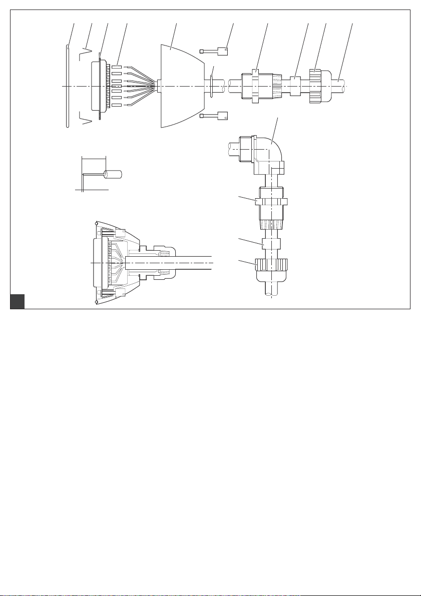
Aufbau des D-Sub-Steckverbinders mit Buchsen- oder Stifteinsatz | Construction of D-Sub plug connector with female insert or pin insert
Montage d'un connecteur D-Sub à douille ou fiches | Struttura del connettore a spina D-Sub con inserto per presa o spina
Estructura del conector por enchufe D-Sub con inserto de casquillo o clavija | Uppbyggnad av D-Sub-kontakt med hon- eller haninsats
A Abisolierungsmaße | Stripping dimensions
Dimensions de dénudation | Misura di spellatura
Medidas de desaislamiento | Lavisoleringsmått
B D-Sub Steckverbinder konfektioniert
Pre-assembled D-Sub plug connector
Connecteur D-Sub assemblé
Connettore a spina D-Sub confezionato
Conector por enchufe D-Sub confeccionado
Belagd D-Sub-kontakt
1 O-Ring | O-ring | Joint torique
O-ring | Anillo toroidal | O-ring
Ø 48 x 2 NBR 70 ±5° Shore
3 D-Sub Buchsen- oder Stifteinsatz
D-Sub female insert or pin insert
D-Sub à douille ou fiches
1)2)
Inserto per presa o spina D-Sub
Inserto de casquillo o clavija D-Sub
D-Sub hon- eller haninsats
1)2)
1)2)
1)2)
1)2)
1)2)
2 Federklemme D-Sub | D-Sub spring clip
Borne à ressorts D-Sub | Fissaggio a molla D-Sub
Borne elástico D-Sub | Fjäderklämma D-Sub
4 Schrumpfschlauch
Tube rétractable
Tubo flexible termocontráctil
3)
| Heat-shrinkable tube3)
3) |
Tubo retrattile3)
3)
| Krympslang
3)
UL94 V-0; GS
5 Gehäuse D-Sub | D-Sub housing | Boîtier D-Sub
Corpo D-Sub | Carcasa D-Sub | D-Sub-hus
6 O-Ring | O-ring | Joint torique
O-ring | Anillo toroidal | O-ring
Perbunan Ø 18 x 1,5 mm
7 Verriegelungsschraube | Locking screw
Vis de verrouillage | Vite di bloccaggio
Tornillo de bloqueo | Låsskruv
8 Muffe | Sleeve | Manchon | Manicotto | Manguito | Muff
PG 13,5
Page 4

9 Einschnittdichtringe für Kabel
2
4
3
5
Notched sealing ring for cable
Bagues d'étanchéité pour câble
Guarnizioni settoriali per cavi
Anillos obturadores con entalladura para cables
10 Überwurfmutter | Tube nut
Écrou de raccordement | Dado di accoppiamento
Tuerca de racor | Överfallsmutter
PG sw PG 13,5
Anpassningsbar tätning för kabel
– schwarz | black | noir | nere | negro | svart
Ø 4,0 – 16,0 mm
– rot | red | rouge | rosse | rojo | röd
Ø 4,0 – 16,0 mm
11 Kabel | Cable | Câble | Cavo | Cable | Kabel
Ø 4,0 – 13,0 mm
12 Winkelverschraubung | Elbow fitting
Raccord d'angle | Raccordo a gomito
Racor acodado | Vinkelskruvkoppling
sw PG 13,5
1)
Crimpversion für D-Sub Buchsen- oder Stiftkontakt | Crimped version for D-Sub bushing or pin contact
Version de sertissage pour D-Sub à douille ou fiches | Versione crimpatura per contatto presa o spina D-Sub
Versión engarzada para contacto de casquillo o clavija D-Sub | Krympversion för D-Sub hon- eller hankontakt
0,20-0,56 mm
2)
Empfohlenes Crimpwerkzeug für | Recommended crimping tools for | Outils de sertissage recommandés pour | Crimpatrice
consigliata per | Herramientas de engarce recomendadas para | Rekommenderat krympverktyg för:
– BW: Strippercrimper | Stripper crimper | Stripper crimper | Stripper crimper | Tenaza engarzadora y pelacables | Krymptång
– EW: Handzange | Hand pliers | Pince de sertissage manuelle | Pinza manuale | Tenaza manual | Handtång
3)
Verwendung empfohlen | Recommended | Utilisation conseillée | Impiego consigliabile | Se recomienda su utilización
Användning rekommenderas
2
BW/EW
AAC (0404-3393-KS)
AMP HD 20 (169341-1)
13
1
D-Sub 25:
Belegung Stecker
Plug assignment
Affectation des fiches
Occupazione connettore
Ocupación del enchufe
Beläggning hankontakt
1
25
14
13
D-Sub 25:
Belegung Buchse
Bushing assignment
Affectation des douilles
Occupazione presa
Ocupación del casquillo
Beläggning honkontakt
14
15
25
1
HD D-Sub 44:
Belegung Stecker
Plug assignment
Affectation des fiches
Occupazione connettore
Ocupación del enchufe
Beläggning hankontakt
0
3322
4483736353433323134342414039
51
13
27262524
121110
9
876
212029
54
1817
3
1
2114
6
12928
1
44
31
15
HD D-Sub 44:
Belegung Buchse
Bushing assignment
Affectation des douilles
Occupazione presa
Ocupación del casquillo
Beläggning honkontakt
16171819
1373839304142434443233343536
23467
20
5
2122
23
81
14 13 12 11 10 9
30 29 28 27 26 25 24
15
31
44
Page 5

AVENTICS | D-Sub | R412008773–BDL–001–AE | Deutsch/English 1
Deutsch
1 Zu dieser Dokumentation
Dieser Konfektionierungsplan enthält wichtige
Informationen für die sichere und sachgerechte
Herstellung der korrekten Konfektionierung einer D-SubSteckerverbindung.
O Lesen Sie daher diesen Konfektionierungsplan, bevor
Sie den Gegenstecker eines D-Sub-Anschlusses
konfektionieren.
O Bewahren Sie diesen Plan so auf, dass er für alle
Benutzer zugänglich ist.
Erforderliche und ergänzende
Dokumentationen
W Bedienungsanleitung des jeweiligen VTS oder der
jeweiligen Modulerweiterung
W Jeweiliger Pinbelegungsplan zur Konfiguration
W Technische Daten und Angaben gemäß Hauptkatalog
2 Sicherheitshinweise
O Beachten Sie die Angaben dieses
Konfektionierungsplans sowie alle mitgeltenden
Dokumente und Begleitunterlagen.
O Halten Sie die nationalen
Unfallverhütungsvorschriften am Einsatzort ein.
O Stellen Sie sicher, dass die Konfektionierung des
Gegensteckers nur von qualifiziertem und geschultem
Fachpersonal durchgeführt wird.
3 Beschreibung und
Einsatzbereich
Der D-Sub-Steckerverbinder besteht aus einer D-SubBuchse und/oder einem D-Sub-Stecker (Aufbau siehe
Abb. 1).
Die Farb-Pin-Zuordnung des D-Sub-Steckverbinders ist in
Tab. 1 dargestellt.
Die Pin-Belegung des jeweiligen Anschlusses ist durch die
gewählte System-Konfiguration vorgegeben.
Hinweis: Beachten Sie bei der Verwendung eines
Anschlusskabels die Hinweise zur Sicherheit und zur
geeigneten Spannungsversorgung in den jeweiligen
Bedienungsanleitungen der angeschlossenen
Komponenten.
Tipp: Vorkonfektionierte Kabel mit passendem D-SubGegenstecker finden Sie im Hauptkatalog.
English
1 About This Documentation
This design plan contains important information on the
safe and appropriate establishment of the correct pin
assignment for a D-Sub plug connector.
O Read this design plan before configuring the mating
plug of the D-Sub connector.
O Keep this scheme in a location where it is accessible to
all users.
Required and supplementary
documentation
W Operating instructions for VTS or module expansion
W Specific pin assignment scheme for configuration
W Technical data and information according to the main
catalog
2 Notes on Safety
O Observe the information contained in this design plan
as well as all related documents and accompanying
documents.
O Adhere to national accident prevention regulations at
the place of installation.
O Ensure that the pin assignment of the mating plug is
only carried out by qualified and trained personnel.
3 Description and applications
The D-Sub plug connector consists of a D-Sub bushing
and/or a D-Sub plug (see structure in fig. 1).
The color pin assignment for the D-Sub plug connector is
shown in tab. 1.
The pin assignment of a connection is stipulated by the
selected configuration.
Note: When using a connection cable, observe the notes on
safety and the correct power supply in the relevant
operating instructions for connected components.
Tip: Pre-assembled cables with suitable D-Sub mating
plugs can be found in the main catalog.
Page 6

AVENTICS | D-Sub | R412008773–BDL–001–AE | Français/Italiano 2
Français
1 A propos de cette
documentation
Ce plan d'assemblage contient des informations
importantes pour effectuer de manière sûre et conforme
l'assemblage correct de connecteurs D-Sub.
O Lire donc attentivement ce plan avant d'assembler la
fiche femelle d'un connecteur D-Sub.
O Ranger ce plan de manière à ce que tous les
utilisateurs puissent y accéder.
Documentations nécessaires et complémentaires
W Modes d'emploi respectifs du VTS et de l'extension de
module
W Plan d'affectation correspondant des broches pour la
configuration
W Données techniques et indications mentionnées dans
le catalogue principal
2 Consignes de sécurité
O Respecter les indications de ce plan d'assemblage, de
tous les autres documents applicables ainsi que des
annexes.
O Respecter les règlements de prévention des accidents
sur le site d'utilisation.
O S'assurer que l'assemblage de la fiche femelle ne soit
effectué que par du personnel qualifié et formé.
3 Description et domaine
d’application
Le connecteur D-Sub se compose d'une douille D-Sub et/
ou d'une fiche D-Sub (montage voir fig. 1).
L'affectation couleur des broches du connecteur D-Sub
est décrite dans le tab. 1.
L'affectation des broches de ce connecteur est déterminée
par la configuration système sélectionnée.
Remarque : Lors de l'utilisation d'un câble de connexion,
s'assurer du respect des consignes de sécurité et des
indications concernant l'alimentation électrique figurant
dans les modes d'emploi respectifs des composants
connectés.
Conseil : Des câbles préassemblés avec fiche femelle
adaptée pour connecteur D-Sub sont disponibles dans
notre catalogue principal.
Italiano
1 Sulla presente
documentazione
Questo piano di confezionamento contiene informazioni
importanti per il corretto confezionamento di un
connettore a spina D-Sub nel rispetto delle norme e della
sicurezza.
O Leggere quindi attentamente questo piano di
confezionamento prima di confezionare la controspina
di un attacco D-Sub.
O Conservare questo piano in modo che sia accessibile a
tutti gli utenti.
Documentazione necessaria e
complementare
W Istruzioni per l'uso della VTS o dell'ampliamento
modulo corrispondenti
W Piano di occupazione pin corrispondente per la
configurazione
W Dati tecnici e dati secondo il catalogo principale
2 Indicazioni di sicurezza
O Osservare i dati di questo piano di confezionamento
nonché tutti gli altri documenti validi e la
documentazione di accompagnamento.
O Rispettare le norme di sicurezza nazionali vigenti in
materia di infortuni sul luogo di impiego.
O Assicurarsi che il confezionamento della controspina
sia eseguito solo da personale tecnico qualificato e
competente.
3 Descrizione e campo
d'impiego
Il connettore a spina D-Sub si compone di una presa
D-Sub e/o un connettore D-Sub a (montaggio ved. fig. 1).
L'assegnazione dei pin colorati del connettore D-Sub è
rappresentata nella tab. 1.
L'occupazione pin dell'attacco corrispondente è stabilita
attraverso la configurazione di sistema selezionata.
Nota: Quando si utilizza un cavo di collegamento,
osservare le indicazioni sulla sicurezza e
sull'alimentazione di tensione adatta nelle rispettive
istruzioni d'uso dei componenti collegati.
Consiglio: Il cavo preconfezionato con controspina D-Sub
adatta è riportato nel catalogo principale.
Page 7

AVENTICS | D-Sub | R412008773–BDL–001–AE | Español/Svenska 3
Español
1 Acerca de esta
documentación
Este esquema de montaje contiene información
importante para efectuar de un modo seguro y apropiado
el correcto montaje de una conexión por enchufe D-Sub.
O Por ello, lea este esquema de montaje antes de montar
el contraenchufe de la conexión D-Sub.
O Guarde este esquema en un lugar al que puedan
acceder fácilmente todos los usuarios.
Documentación necesaria y
complementaria
W Instrucciones de servicio del respectivo VTS o de la
respectiva ampliación del módulo
W Esquema de ocupación de pines correspondiente a la
configuración
W Datos técnicos y especificaciones según el catálogo
principal
2 Indicaciones de seguridad
O Tenga en cuenta las indicaciones de este esquema de
montaje, así como todos los documentos también
vigentes y documentos adicionales.
O Respete las normas nacionales de prevención de
accidentes en el lugar de aplicación.
O Asegúrese de que el montaje del contraenchufe sea
efectuado sólo por personal técnico cualificado y
capacitado.
3 Descripción y zonas de
utilización
El conector por enchufe D-Sub consiste en un casquillo DSub y/o en un enchufe D-Sub (estructura, véase la fig. 1).
En la tab. 1 se representa la asignación de colores de los
pines del conector por enchufe D-Sub.
La ocupación de pines de la respectiva conexión viene
dada por la configuración de sistema seleccionada.
Nota: Al usar un cable de conexión, tenga en cuenta las
indicaciones de seguridad y las indicaciones relativas a la
alimentación de tensión adecuada que figuran en las
respectivas instrucciones de servicio de los componentes
conectados.
Consejo: Encontrará un cable premontado con el
correspondiente contraenchufe D-Sub en el catálogo
principal.
Svenska
1 Om denna dokumentation
Detta beläggningsschema innehåller viktig information för
säker och fackmannamässig beläggning i en D-Subanslutning.
O Läs därför detta beläggningsschema innan D-Sub-
anslutningens motkontakt konfigureras.
O Förvara schemat så att det är lättillgängligt för alla
som behöver använda det.
Nödvändig och kompletterande
dokumentation
W Bruksanvisning för respektive VTS eller
modulutökning
W Berört stiftbeläggningsschema för konfiguration
W Tekniska data och uppgifter enligt huvudkatalogen
2 Säkerhetsföreskrifter
O Observera uppgifterna i detta beläggningsschema och
alla andra gällande dokument och medföljande
underlag.
O Iaktta de gällande nationella föreskrifterna för
förebyggande av olycksfall.
O Kontrollera att motkontaktens stiftbeläggning endast
utförs av kvalificerad och utbildad fackpersonal.
3 Beskrivning och
användningsområde
D-Sub-anslutningen har en D-Sub-honkontakt och/eller
en D-Sub-hankontakt (för uppbyggnad, fig. 1).
Färgen för respektive stift i D-Sub-kontakten visas i tab. 1.
Stiftbeläggningen för respektive anslutning beror på den
valda konfigurationen.
Anmärkning: Observera anvisningarna om säkerhet och
lämplig strömförsörjning i bruksanvisningarna för de
anslutna komponenterna vid användning av en
anslutningskabel.
Tips: Förtillverkade kablar med passande D-Submotkontakter finns i huvudkatalogen
Page 8

AVENTICS GmbH
Ulmer Straße 4
30880 Laatzen
Phone +49 (0) 5 11-21 36-0
Fax: +49 (0) 511-21 36-2 69
www.aventics.com
info@aventics.com
Further addresses:
www.aventics.com/en/contact
The data specified above only serve to
describe the product. No statements
concerning a certain condition or
suitability for a certain application can
be derived from our information. The
given information does not release the
user from the obligation of own
judgement and verification. It must be
remembered that our products are
subject to a natural process of wear
and aging.
An example configuration is depicted
on the title page. The delivered
product may thus vary from that in the
illustration.
Translation of the original operating
instructions. The original operating
instructions were created in the
German language.
R412008773–BDL–001–AE/07.2015
Subject to modifications. © All rights
reserved by AVENTICS GmbH, even
and especially in cases of proprietary
rights applications. It may not be
reproduced or given to third parties
without its consent.
 Loading...