

Page 1
Montageanleitung | Assembly instructions | Instructions de montage |
Istruzioni di montaggio | Instrucciones de montaje | Monteringsanvisning
Buskoppler und E/A-Modul
Bus coupler and I/O module
Coupleur de bus et module E/S
Accoppiatore bus e modulo I/O
Acoplador de bus y módulo E/S
Bussomkopplare och I/O-modul
AES
R412018134/06.2016, Replaces: 03.2014, DE/EN/FR/IT/ES/SV
Page 2

9
1
2
4
3
UA
IO/DIAG
RUN/BF
R412015318
AES-D-BC-POP
2
5
1
7
6
8
Einheit aus Ventilen der Serie AV und einer AES-Einheit/Unit composed of AV series valves and an AES unit/
Unité composée de distributeurs de série AV et d’une unité AES/Unità composta da valvole della serie AV e da un'unità AES/
Unidad formada por válvulas de la serie AV y una unidad AES/Enhet av ventiler i serie AV och en AES-enhet
4
3
UA
IO/DIAG
RUN/BF
R412015318
AES-D-BC-POP
5
2
1
AES-Einheit als Standalone-Variante/AES unit as stand-alone variant/Unité AES en tant que variante Stand Alone/
Unità AES come variante stand-alone/Unidad AES como variante Stand-Alone/AES-enhet som stand-alone-variant
Page 3

UL
10
10
8
4
7
6
5
12
2
3
9
9
10
11
13
R
4
1
2
0
1
8
2
1
8
A
E
S
-
D
-
B
C
-
E
C
A
T
1
3
10
4
11
6
5
13
11
9
9
8
7
1
2
3
5
12
4
5
6
7
1.
2.
8
9
10
R
4
1
2
0
1
8
2
1
8
A
E
S
D
-
B
C
E
C
A
T
11
UA
IO/DIAG
RUN/BF
Buskoppler/Bus coupler/Coupleur de bus/
Accoppiatore bus/Acoplador de bus/Bussomkopplare
UA
DIAG
0
1
3
X2O2
O1
X2
2
X2O3
4
R412015333
8DO8M8
5
X2O4
X2O5
6
7
X2O6
X2O8
X2O7
Modul trennen/Remove the module/Séparation du module/
Separazione del modulo/Separación del módulo/Lossa modulen
Federklemmelement einsetzen und bis zum Anschlag hochziehen/
Position the spring clamp element and pull it up to the stop/
Insertion de l’élément de serrage élastique et tirage vers le
haut jusqu’à la butée/Inserimento e sollevamento verso l'alto
dell'elemento di fissaggio a molla fino alla battuta/
Inserción del elemento de fijación de resorte y extracción
hacia arriba hasta el tope/Sätt i fjäderklämman och dra upp
den till anslaget
E/A-Modul / I/O module / Module E/S /
Modulo I/O / Módulo E/S / I/O-modul
Typenschild/Rating plate/Plaque signalétique/
Targhetta di identificazione/Placa de características/Typskylt
Federklemmelement lösen und bis zum Anschlag hochziehen/
Release the spring clamp element and pull it up to the stop/
Desserrage de l’élément de serrage élastique et tirage vers le
haut jusqu’à la butée/Svitamento e sollevamento verso l'alto
dell'elemento di fissaggio a molla fino alla battuta/Soltado del
elemento de fijación de resorte y extracción hacia arriba hasta
el tope/Lossa fjäderklämman och dra upp den till anslaget
Module zusammensetzen/Assemble the modules/Assemblage des modules/
Assemblaggio dei moduli/Unión de módulos/Sätt ihop modulerna
Federklemmelement eindrücken/Press down the spring clamp
element/Enfoncement de l’élément de serrage élastique/
Pressione dell'elemento di fissaggio a molla/Inserción del
elemento de fijación de resorte/Tryck in fjäderklämman
UL
UA
G
A
I
D
O/
I
/BF
UN
R
Buskoppler rechts befestigen/Fasten bus coupler on the
right/Fixation du coupleur de bus à droite/Fissaggio
l'accoppiatore bus a destra/Fijación del acoplador de bus a la
derecha/Fäst fältbussnoden till höger
Page 4

3
AVENTICS | AES | R412018134–BAL–001–AD/06.2016 | Deutsch 1
1 Zu dieser Dokumentation
Gültigkeit der Dokumentation
Diese Dokumentation gilt für Buskoppler und für E/A-Module der
Serie AES.
Diese Dokumentation richtet sich an Monteure.
O Lesen Sie diese Dokumentation vollständig und insbesondere
das Kapitel „Sicherheitshinweise“, bevor Sie mit dem Produkt
arbeiten.
Erforderliche und ergänzende
Dokumentationen
O Nehmen Sie das Produkt erst in Betrieb, wenn Ihnen die
folgenden Dokumentationen vorliegen und Sie diese beachtet
und verstanden haben:
W Montageanleitung des Ventilsystems AV
W Systemhandbuch des Buskopplers (nur auf CD)
W Anlagendokumentation
Wenn pneumatische Komponenten im Ventilsystem vorhanden
sind:
W Dokumentation der pneumatischen Komponenten
Wenn Eingangs- oder Ausgangsmodule in der Einheit vorhanden
sind:
W Systemhandbuch der E/A-Module (nur auf CD)
Alle Anleitungen außer der Anlagendokumentation finden
Sie auch auf der CD R412018133.
Darstellung von Informationen
Sicherheitshinweise
In dieser Dokumentation stehen Sicherheitshinweise vor einer
Handlungsabfolge, bei der die Gefahr von Personen- oder
Sachschäden besteht. Die beschriebenen Maßnahmen zur
Gefahrenabwehr müssen eingehalten werden.
Sicherheitshinweise sind wie folgt aufgebaut:
SIGNALWORT
Art und Quelle der Gefahr
Folgen bei Nichtbeachtung
O Maßnahme zur Gefahrenabwehr
O <Aufzählung>
Warnzeichen,
Signalwort
GEFAHR
VORSICHT
ACHTUNG
Bedeutung
kennzeichnet eine gefährliche Situation, in der Tod oder schwere Körperverletzung eintreten werden, wenn sie
nicht vermieden wird
kennzeichnet eine gefährliche Situation, in der leichte bis mittelschwere
Körperverletzungen eintreten können,
wenn sie nicht vermieden wird
Sachschäden: Das Produkt oder die
Umgebung können beschädigt werden
Symbole
Wenn diese Information nicht beachtet wird, kann das zu
Verschlechterungen im Betriebsablauf führen.
2 Sicherheitshinweise
Zu diesem Kapitel
Das Produkt wurde gemäß den allgemein anerkannten Regeln der
Technik hergestellt. Trotzdem besteht die Gefahr von Personenund Sachschäden, wenn Sie dieses Kapitel und die
Sicherheitshinweise in dieser Dokumentation nicht beachten.
O Lesen Sie diese Dokumentation gründlich und vollständig,
bevor Sie mit dem Produkt arbeiten.
O Bewahren Sie die Dokumentation so auf, dass sie jederzeit für
alle Benutzer zugänglich ist.
O Geben Sie das Produkt an Dritte stets zusammen mit den
erforderlichen Dokumentationen weiter.
Bestimmungsgemäße Verwendung
Buskoppler: Der Buskoppler dient zum Anschluss von E/A-
Modulen und Ventilen an ein Feldbussystem. Er darf ausschließlich
für das Protokoll verwendet werden, dass im aufgedruckten SPSKonfigurationsschlüssel ( –1) aufgeführt ist. Der Buskoppler
darf ausschließlich an Ventile der Serie AV und an E/A-Module der
Serie AES angeschlossen werden.
E/A-Modul: E/A-Module dienen zum Anschluss von elektrischen
Betriebsmitteln wie Sensoren oder Ventilen. Das E/A-Modul darf
ausschließlich an Geräte der Serie AES angeschlossen werden.
Alle Module: Die Module sind für den professionellen Gebrauch
und nicht für die private Verwendung bestimmt.
Sie dürfen die Module nur im industriellen Bereich einsetzen
(Klasse A). Für den Einsatz im Wohnbereich (Wohn-, Geschäftsund Gewerbebereich) ist eine Einzelgenehmigung bei einer
Behörde oder Prüfstelle einzuholen. In Deutschland werden solche
Einzelgenehmigungen von der Regulierungsbehörde für
Telekommunikation und Post (RegTP) erteilt.
Das Produkt darf in sicherheitsgerichteten Steuerungsketten
verwendet werden, wenn die Gesamtanlage darauf ausgerichtet ist.
Die bestimmungsgemäße Verwendung schließt auch ein, dass Sie
diese Dokumentation und insbesondere das Kapitel
„Sicherheitshinweise“ vollständig gelesen und verstanden haben.
Einsatz in explosionsgefährdeten Bereichen
Weder Buskoppler noch E/A-Module sind ATEX-zertifiziert. Nur
ganze Ventilsysteme können ATEX-zertifiziert sein. Ventilsysteme
dürfen nur dann in Bereichen in explosionsfähiger Atmosphäre
eingesetzt werden, wenn das Ventilsystem eine ATEXKennzeichnung trägt!
O Beachten Sie stets die technischen Daten und die auf dem
Typenschild der gesamten Einheit angegebenen Grenzwerte,
insbesondere die Daten aus der ATEX-Kennzeichnung.
ATEX-Kennzeichnung
Das Modul hat keine eigene ATEX-Kennzeichnung.
Nicht bestimmungsgemäße Verwendung
Zur nicht bestimmungsgemäßen Verwendung des Produkts
gehört der Einsatz des Moduls als Sicherheitsbauteil.
Die Risiken bei nicht bestimmungsgemäßer Verwendung liegen
allein beim Benutzer.
Page 5

AVENTICS | AES | R412018134–BAL–001–AD/06.2016 | Deutsch 2
Qualifikation des Personals
Die in dieser Dokumentation beschriebenen Tätigkeiten erfordern
grundlegende Kenntnisse der Mechanik, Elektrik und Pneumatik
sowie Kenntnisse der zugehörigen Fachbegriffe. Um die sichere
Verwendung zu gewährleisten, dürfen diese Tätigkeiten daher nur
von einer entsprechenden Fachkraft oder einer unterwiesenen
Person unter Leitung einer Fachkraft durchgeführt werden.
Eine Fachkraft ist, wer aufgrund seiner fachlichen Ausbildung,
seiner Kenntnisse und Erfahrungen sowie seiner Kenntnisse der
einschlägigen Bestimmungen die ihm übertragenen Arbeiten
beurteilen, mögliche Gefahren erkennen und geeignete
Sicherheitsmaßnahmen treffen kann. Eine Fachkraft muss die
einschlägigen fachspezifischen Regeln einhalten.
Allgemeine Sicherheitshinweise
W Beachten Sie die gültigen Vorschriften zur Unfallverhütung
und zum Umweltschutz.
W Berücksichtigen Sie die Bestimmungen für
explosionsgefährdete Bereiche.
W Beachten Sie die Sicherheitsvorschriften und -bestimmungen
des Landes, in dem das Produkt eingesetzt/angewendet wird.
W Verwenden Sie Produkte von AVENTICS nur in technisch
einwandfreiem Zustand.
W Beachten Sie alle Hinweise auf dem Produkt.
W Verwenden Sie nur vom Hersteller zugelassene Zubehör- und
Ersatzteile.
W Halten Sie die in der Produktdokumentation angegebenen
technischen Daten und Umgebungsbedingungen ein.
W Sie dürfen das Produkt erst dann in Betrieb nehmen, wenn
festgestellt wurde, dass das Endprodukt (beispielsweise eine
Maschine oder Anlage), in das die Produkte von AVENTICS
eingebaut sind, den länderspezifischen Bestimmungen,
Sicherheitsvorschriften und Normen der Anwendung
entspricht.
W Buskoppler und E/A Module enthalten elektrostatisch
empfindlichen Bauteile. Diese können durch elektrostatische
Entladung beim Berühren zerstört werden. Nehmen Sie die
Geräte erst nach einem Potentialausgleich aus dem ESDSchutzbeutel heraus. Vermeiden Sie die direkte Berührung von
elektronischen Bauteilen.
Produkt- und technologieabhängige
Sicherheitshinweise
GEFAHR
Explosionsgefahr beim Arbeiten in explosionsfähiger
Atmosphäre!
Wenn
die Anlage, in die die Einheit eingebaut werden soll, von
explosionsfähiger Atmosphäre umgeben ist, kann sich diese
Arbeiten
beim
O Berücksichtigen Sie immer die lokalen
Errichtungsbestimmungen.
O Führen Sie Arbeiten nur in explosionsfreier Atmosphäre
und bei vorliegendem Feuer-Erlaubnisschein durch. Wenn
Sie trotzdem mit dem Vorhandensein von explosionsfähiger
Atmosphäre rechnen müssen, verwenden Sie nur nicht
funkendes Werkzeug.
Explosionsgefahr bei fehlendem Schlagschutz!
Mechanische Beschädigungen, z. B. durch Belastung der
Steckverbinder, führen zum Verlust der Schutzart IP65/IP67.
O Stellen Sie sicher, dass das Betriebsmittel in
explosionsgefährdeten Bereichen gegen jegliche
mechanische Beschädigung geschützt eingebaut wird.
Explosionsgefahr durch Funkenbildung!
Eine elektrostatische Aufladung der Einheit kann zu
Funkenbildung führen und stellt in Ex-Schutzzonen eine
Explosionsgefahr dar.
O Vermeiden Sie eine elektrostatische Aufladung, z. B. indem
Sie die AES-Einheit erden.
Explosionsgefahr durch Überspannung!
Das Modul ist als Betriebsmittel mit niedriger Energie definiert
und muss in explosionsgefährdeten Bereichen gegen
Überspannung geschützt werden.
O Stellen Sie sicher, dass in explosionsgefährdeten Bereichen
die Spannungsversorgung gegen Überspannung geschützt
ist.
entzünden
.
Explosionsgefahr durch Zirkulationsströme!
Magnetische Streufelder können Zirkulationsströme
verursachen, z. B.
W in der Nähe von elektrischen Antrieben bei unsymmetrischer
Last,
W bei Elektroschweißen, wenn die Masse über die Anlage und
nicht über eine 0 V-Leitung geleitet wird
W oder bei kathodischem Korrosionsschutz.
O Stellen Sie sicher, dass ein Schutz gegen mögliche Effekte
von Zirkulationsströmen besteht.
Page 6

1
2
3
AVENTICS | AES | R412018134–BAL–001–AD/06.2016 | Deutsch 3
VORSICHT
Verbrennungsgefahr durch heiße Oberflächen!
Berühren der Oberflächen der Einheit und der benachbarten
Teile im laufenden Betrieb kann zu Verbrennungen führen.
O Lassen Sie den relevanten Anlagenteil abkühlen, bevor Sie
an der Einheit arbeiten.
O Berühren Sie den relevanten Anlagenteil nicht im laufenden
Betrieb.
Verletzungsgefahr durch Montage unter Druck oder
Spannung!
Die Montage unter Druck oder anliegender elektrischer
Spannung kann zu Verletzungen führen.
O Schalten Sie den relevanten Anlagenteil drucklos und
spannungsfrei, bevor Sie das Produkt montieren.
O Sichern Sie die Anlage gegen Wiedereinschalten.
Pflichten des Betreibers
Als Betreiber der Anlage, die mit Modulen der Serie AES
ausgestattet werden soll, sind Sie dafür verantwortlich,
W dass die bestimmungsgemäße Verwendung sichergestellt ist,
W dass das Bedienpersonal regelmäßig unterwiesen wird,
W dass die Einsatzbedingungen den Anforderungen an die
sichere Verwendung des Produktes entsprechen,
W dass Reinigungsintervalle gemäß den
Umweltbeanspruchungen am Einsatzort festgelegt und
eingehalten werden,
W dass Zündgefahren, die durch den Einbau von Betriebsmitteln
in Ihrer Anlage entstehen, berücksichtigt werden,
W dass bei einem aufgetretenen Defekt keine eigenmächtigen
Reparaturversuche unternommen werden.
3 Allgemeine Hinweise zu
Sachschäden und
Produktschäden
ACHTUNG
Verlust der IP-Schutzart durch Verbiegen der
Federklemmelemente!
O Ziehen Sie die Federklemmelemente immer bis zum
Anschlag hoch, bevor Sie die Module zusammensetzen.
4 Lieferumfang
W 1 Buskoppler oder E/A-Modul der Serie AES
W Beim Buskoppler: 3 Befestigungsschrauben
W Bei E/A-Modulen: 2 Federklemmelemente
W 1 CD (R412018133)
W 1 Montageanleitung R412018134
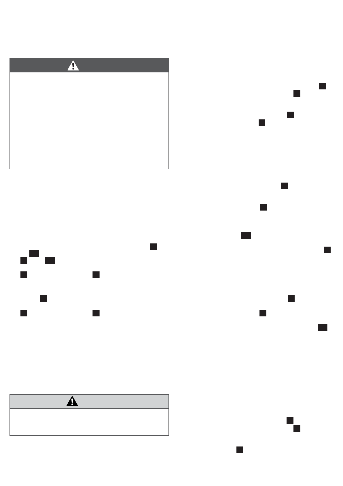
5 Zu diesem Produkt
Buskoppler und E/A-Module sind in verschiedenen Ausführungen
erhältlich. Die Steckerbelegung kann von den Abbildungen
abweichen.
Ventilsystem der Serie AV
1 Endplatte links
2 E/A-Module der Serie AES
3 Buskoppler der Serie AES
4 Adapterplatte
5 pneumatische Einheit der Serie AV
6 elektrische Einheit der Serie AES
7 Haltewinkel
8 Aussparung für Haltewinkel
9 Typenschild mit Konfigurationsschlüssel
AES-Einheit als Stand-alone-Variante
1 Endplatte links
2 E/A-Module der Serie AES
3 Buskoppler der Serie AES
4 Endplatte rechts für Stand-alone-Variante
5 Typenschild
ACHTUNG
Mechanische Belastungen!
Moduls
Beschädigung des
O Stellen Sie sicher, dass das Modul nicht mechanisch
belastet wird, z. B. durch Verspannen der Einheit bei der
Befestigung an der Montagefläche.
O Beachten Sie, dass die Gesamteinheit während und nach
der Montage sowie beim Transport mindestens alle 150 mm
unterstützt wird, um ein Durchbiegen oder Verspannen zu
verhindern.
O Verwenden Sie zur Befestigung an der Montagefläche
Haltewinkel, wenn Sie mehr als drei E/A-Module montieren.
!
Buskoppler
1 Identifikationsschlüssel
2 LEDs (Beschreibung siehe Systemhandbuch)
3 Sichtfenster
4 Feld für Betriebsmittelkennzeichnung
5 Anschluss Feldbus (siehe Systemhandbuch)
6 Anschluss Feldbus (siehe Systemhandbuch)
7 Anschluss Spannungsversorgung X1S
8 Funktionserde
9 Steg für Montage des Federklemmelements
10 Befestigungsschrauben zur Befestigung an der Adapterplatte
11 elektrischer Anschluss für AES-Module
12 Typenschild
13 elektrischer Anschluss für AV-Module
Page 7

1
1
1
6
173
3
3113
4
5
1112
11
1
1
AVENTICS | AES | R412018134–BAL–001–AD/06.2016 | Deutsch 4
Eingangsmodul/Ausgangsmodul
1 SPS-Konfigurationsschlüssel
2 LEDs (Beschreibung siehe Systemhandbuch)
3 LED für Ausgangs- oder Eingangssignale
4 Feld für Betriebsmittelkennzeichnung
5 Nut für Montage des Federklemmelements
6 Feld für Kanal- und Steckerbeschriftung
7 Anschluss für zusätzliche Spannungsversorgung (optional
vorhanden)
8 Funktionserde (optional vorhanden)
9 Steg für Montage des Federklemmelements
10 Signaleingang/-ausgang
11 elektrischer Anschluss für AES-Module
12 Typenschild
13 Aussparung für Haltewinkel
Identifikation des Produkts
Informationen zum SPS-Konfigurationsschlüssel finden Sie in der
Systembeschreibung des Moduls.
Informationen auf dem Typenschild siehe .
Das dargestellte Typenschild ist ein Muster.
O Überprüfen Sie anhand der Materialnummer auf dem
Typenschild, ob das Modul mit Ihrer Bestellung übereinstimmt.
E/A-Module werden wie folgt befestigt:
W rechts mit den beiden mitgelieferten Federklemmelementen
an einem Buskoppler ( –3) oder E/A-Modul,
W links mit zwei Federklemmelementen an einem E/A-Modul
(–2) oder an der linken Endplatte ( –1).
Die Federklemmelemente sind auf der rechten Seite der E/AModule und der linken Endplatte verliergesichert befestigt.
Austausch und Erweiterung vorbereiten
1. Stellen Sie sicher, dass die Atmosphäre nicht explosiv ist,
wenn Sie am Gerät arbeiten müssen.
2. Schalten Sie den relevanten Anlagenteil druck- und stromlos.
3. Trennen Sie die elektrischen Anschlüsse des Buskopplers und
der E/A-Module, wenn dies für die Montage des Moduls
notwendig ist.
VORSICHT
Verletzungsgefahr bei hängend montierter Einheit!
Teile der Einheit können herunterfallen und Verletzungen
verursachen.
O Stützen Sie die Einheit ab, bevor Sie mit der Demontage
beginnen.
6 Modulaustausch und
Erweiterung der Einheit
GEFAHR
Explosionsgefahr!
Arbeiten am Gerät in explosionsfähiger Atmosphäre kann zu
Explosionen führen.
O Stellen Sie sicher, dass die Atmosphäre nicht explosiv ist,
wenn Sie am Gerät arbeiten müssen.
Beim Ziehen von Steckern unter Spannung können große
Potenzialunterschiede entstehen, die in explosiver Atmosphäre
zur Explosion führen können.
O Trennen Sie das Gerät in explosiver Atmosphäre niemals
von der Spannung.
O Lösen Sie in explosiver Atmosphäre niemals die
Federklemmelemente an den Modulen.
Die Einheit wurde nach Ihren Angaben individuell konfiguriert und
komplett verschraubt ausgeliefert. Sie können jedoch Buskoppler
und E/A-Module austauschen sowie E/A-Module anbauen oder
entfernen.
O Dokumentieren Sie stets alle Änderungen an Ihrer
Konfiguration.
Die Montage der gesamten Einheit ist in der Montageanleitung für
das Ventilsystem ausführlich beschrieben.
Befestigungsart der Module
Buskoppler werden wie folgt befestigt:
W rechts mit drei Schrauben an der Adapterplatte ( –4 und
) oder an der rechten Endplatte für die Stand-alone-
Variante ( –4 und ),
W links mit zwei Federklemmelementen an einem E/A-Modul
(–2) oder an der linken Endplatte ( –1).
Buskoppler austauschen
Buskoppler demontieren
1. Entfernen Sie die Schrauben, mit denen die linke Endplatte an
der Montagefläche montiert ist.
2. Lösen Sie z. B. mit einem Schraubendreher die
Federklemmelemente zwischen Buskoppler und E/A-Modul
bzw. zwischen Buskoppler und linker Endplatte und ziehen Sie
diese bis zum Anschlag hoch .
3. Entfernen Sie ggf. die Haltewinkel ( –7) an den E/A-Modulen.
4. Ziehen Sie alle Komponenten nach links weg, bis diese nicht
mehr mit dem Buskoppler verbunden sind .
5. Lösen Sie die Befestigungsschrauben
Antrieb: Ejot TORX PLUS®/AUTOSERT® 20IP
6. Ziehen Sie den Buskoppler nach links von der Adapter- oder
Endplatte ab.
Neuen Buskoppler montieren
1. Prüfen Sie anhand der Materialnummer auf dem Typenschild,
ob Sie den richtigen Buskoppler tauschen.
2. Montieren Sie die Beschriftungsschilder des alten Buskopplers
auf den neuen Buskoppler oder beschriften Sie das Feld für die
Betriebsmittelkennzeichnung ( –4) am neuen Buskoppler.
3. Stellen Sie die Schalter des neuen Buskopplers analog zum
alten Buskoppler ein. Öffnen Sie dazu das Sichtfenster ( –3).
Achten Sie beim Verschließen des Sichtfensters auf den
korrekten Sitz der Dichtungen.
4. Setzen Sie den neuen Buskoppler auf die Montagefläche und
schieben Sie ihn nach rechts auf die Adapterplatte oder auf die
Endplatte für die Stand-alone-Variante auf . Stellen Sie
dabei sicher, dass die Dichtungen richtig eingelegt sind.
5. Setzen Sie die drei Befestigungsschrauben ( –10) in die
Durchgangsbohrungen auf der linken Seite des Buskopplers
ein und ziehen Sie die Schrauben fest.
Anzugsmoment: 1,5 Nm–1,8 Nm mit Antrieb Ejot TORX
PLUS®/AUTOSERT® 20IP
(–10). Empfohlener
Page 8

6
9106
1
7
8
4
6
9
10
6
8
4
4
6
9
10
AVENTICS | AES | R412018134–BAL–001–AD/06.2016 | Deutsch 5
E/A-Module und Endplatte wieder montieren
1. Ziehen Sie die beiden Federklemmelemente auf der rechten
Seite der zuvor entfernten E/A-Module bis zum Anschlag hoch
.
2. Setzen Sie die zuvor entfernten Module auf die Montagefläche
und schieben Sie diese nach rechts auf die Einheit auf .
Stellen Sie dabei sicher, dass die Dichtungen richtig eingelegt
sind.
3. Drücken Sie die beiden Federklemmelemente bis zum
Anschlag nach unten .
Alle Module sind jetzt mit der Einheit verbunden.
4. Schrauben Sie die Endplatte und ggf. die Haltewinkel wieder
an der Montagefläche fest.
5. Schließen Sie die elektrischen Anschlüsse der Einheit wieder
gemäß der Beschriftung an.
E/A-Modul austauschen
E/A-Modul demontieren
1. Entfernen Sie die Schrauben, mit denen die linke Endplatte an
der Montagefläche montiert ist.
2. Lösen Sie z. B. mit einem Schraubendreher alle erforderlichen
Federklemmelemente und ziehen Sie diese bis zum Anschlag
hoch .
3. Entfernen Sie ggf. die Haltewinkel ( –7) an den E/A-Modulen.
4. Ziehen Sie alle Komponenten nach links weg, bis diese nicht
mehr verbunden sind .
5. Entfernen Sie das gewünschte E/A-Modul.
Einheit mit einem E/A-Modul erweitern
Wir empfehlen Ihnen die E/A-Module nach links zu
erweitern.
Endplatte demontieren
1. Entfernen Sie die Schrauben, mit denen die linke Endplatte an
der Montagefläche montiert ist.
2. Lösen Sie z. B. mit einem Schraubendreher die
Federklemmelemente zwischen E/A-Modul und linker
Endplatte und ziehen Sie die beiden Federklemmelemente bis
zum Anschlag hoch .
3. Ziehen Sie die Endplatte nach links weg, bis diese nicht mehr
mit dem E/A-Modul verbunden ist.
Federklemmelement in das E/A-Modul einsetzen
Bei neuen E/A-Modulen werden zwei Federklemmelemente
separat mitgeliefert.
1. Setzen Sie die mitgelieferten Federklemmelemente auf das
E/A-Modul und drücken Sie diese in die Nut, bis sie einrasten
.
Die Federklemmelemente sind jetzt verliergesichert.
Hinweis!
2. Ziehen Sie die Federklemmelemente immer bis zum Anschlag
hoch, bevor Sie die Module zusammensetzen.
Neues E/A-Modul montieren
1. Prüfen Sie anhand der Materialnummer auf dem Typenschild,
ob Sie das richtige E/A-Modul tauschen.
2. Montieren Sie die Bezeichnungsschilder des alten E/A-Moduls
auf das neue E/A-Modul oder beschriften Sie das neue E/A-
(–4)
Modul
3. Ziehen Sie die beiden Federklemmelemente am neuen E/A-
Modul bis zum Anschlag hoch .
4. Setzen Sie das neue E/A-Modul auf die Montagefläche und
schieben Sie es nach rechts auf die Einheit auf . Stellen Sie
dabei sicher, dass die Dichtungen richtig eingelegt sind.
5. Drücken Sie die beiden Federklemmelemente bis zum
Anschlag nach unten .
Das Modul ist jetzt mit der Einheit verbunden.
6. Wiederholen Sie die Schritte 3.–5. für die zuvor entfernten
Module.
7. Schrauben Sie die Endplatte und ggf. die Haltewinkel wieder
an der Montagefläche fest.
8. Schließen Sie die elektrischen Anschlüsse der Einheit wieder
gemäß der Beschriftung an.
.
ACHTUNG
Mechanische Belastungen!
Beschädigung des
O Verwenden Sie zur Befestigung an der Montagefläche
Haltewinkel, wenn Sie mehr als drei E/A-Module montieren.
Der Abstand der Haltewinkel darf maximal 150 mm
betragen.
1. Prüfen Sie anhand der Materialnummer auf dem Typenschild,
ob Sie das richtige E/A-Modul einbauen.
2. Beschriften Sie am E/A-Modul gemäß der kundenspezifischen
Dokumentation
– das Feld für die Betriebsmittelkennzeichnung ( –4),
– die Felder zur Steckerkennzeichnung ( –6)
– und alle Rundsteckverbinder.
3. Ziehen Sie die beiden Federklemmelemente am neuen E/A-
Modul bis zum Anschlag hoch .
4. Setzen Sie das neue E/A-Modul auf die Montagefläche und
schieben Sie es nach rechts auf das letzte E/A-Modul .
Stellen Sie dabei sicher, dass die Dichtungen richtig eingelegt
sind.
5. Drücken Sie die beiden Federklemmelemente bis zum
Anschlag nach unten .
Das Modul ist jetzt mit der Einheit verbunden.
6. Wiederholen Sie die Schritte 3.–5. für die Endplatte.
7. Montieren Sie ggf. Haltewinkel an den E/A-Modulen.
8. Schrauben Sie die Endplatte und ggf. die Haltewinkel wieder
an der Montagefläche fest.
9. Schließen Sie die elektrischen Anschlüsse der Einheit wieder
gemäß der Beschriftung an.
Moduls
!
Page 9

AVENTICS | AES | R412018134–BAL–001–AD/06.2016 | Deutsch 6
Das neue Modul muss in der Steuerung konfiguriert
werden. Sie benötigen dazu ihre kundenspezifische
Dokumentation. Beachten Sie dazu den entsprechenden
Abschnitt aus dem Systemhandbuch des Buskopplers und
des E/A-Moduls.
7 Inbetriebnahme und Bedienung
GEFAHR
Explosionsgefahr bei fehlendem Schlagschutz!
Mechanische Beschädigungen, z. B. durch Belastung der
Steckverbinder, führen zum Verlust der Schutzart IP65/IP67.
O Stellen Sie sicher, dass das Gerät in explosionsgefährdeten
Bereichen gegen jegliche mechanische Beschädigung
geschützt eingebaut wird.
Explosionsgefahr durch beschädigte Gehäuse!
In explosionsgefährdeten Bereichen können beschädigte
Gehäuse zur Explosion führen.
O Stellen Sie sicher, dass die Komponenten des Ventilsystems
nur mit vollständig montiertem und unversehrtem Gehäuse
betrieben werden.
9 Technische Daten
Allgemeine Daten
Abmessungen
B x H x T
Gewicht Buskoppler: 0,160–0,175 kg mit Befestigungs-
Temperaturbereich
Anwendung
Temperaturbereich
Lagerung
Einbaulage beliebig
Spannungsversorgung
Buskoppler: 37,5 mm x 52 mm x 102 mm
E/A-Modul: 50 mm x 34 mm x 82 mm
schrauben, abhängig vom Feldbus
E/A-Modul: 0,11 kg
-10 °C bis 60 °C
-25 °C bis 80 °C
Buskoppler:
Elektronik: 24 V DC ±25%
Ventile: 24 V DC ±10%
Die Spannungsversorgung muss aus einem
Netzteil mit sicherer Trennung erfolgen.
E/A-Modul:
koppler
über die Backplane durch den Bus-
Explosionsgefahr durch fehlende Dichtungen und
Verschlüsse!
Flüssigkeiten und Fremdkörper können in das Gerät eindringen
und das Gerät zerstören.
O Stellen Sie sicher, dass die Dichtungen im Stecker
vorhanden und nicht beschädigt sind.
O Stellen Sie vor der Inbetriebnahme sicher, dass alle Stecker
montiert sind.
Einstellhinweise finden Sie in den Systembeschreibungen auf der
beiliegenden CD (R412018133).
O Beachten Sie bei der Inbetriebnahme des relevanten
Anlagenteils immer die Anlagendokumentation.
8 Entsorgung
O Entsorgen Sie das Modul daher nach den Bestimmungen Ihres
Landes.
Schutzart nach
EN 60529/
IEC529
O Entnehmen Sie weitere technischen Daten für Ihre
Konfiguration dem Typenschild und den Katalogblättern des
Online-Produktkatalogs von AVENTICS.
IP65/IP67 (nur in montiertem Zustand und mit
allen montierten Steckern)
10 Zubehör
Bezeichnung Materialnummer
Haltewinkel, 10 Stück R412018339
Federklemmelement, 10 Stück inkl. Montageanleitung
Endplatte links R412015398
Endplatte rechts für Stand-alone-Variante R412015741
R412015400
Page 10
3
AVENTICS | AES | R412018134–BAL–001–AD/06.2016 | English 7
1 About This Documentation
Documentation validity
This documentation is valid for bus couplers and I/O modules from
the AES series.
This documentation is intended for installers.
O Read this documentation completely, especially the chapter
“Sicherheitshinweise” before working with the product.
Required and supplementary documentation
O Only commission the product once you have obtained the
following documentation and understood and complied with its
contents.
W Assembly instructions for the AV valve system
W System manual for the bus coupler (only on CD)
W System documentation
If the valve system contains pneumatic components:
W Documentation for the pneumatic components
If the unit contains input or output modules:
W System manual for the I/O modules (only on CD)
You can also find all instructions, with the exception of the
system documentation, on the CD R412018133.
Presentation of information
Safety instructions
This documentation contains safety instructions before any steps
that involve a risk of personal injury or damage to equipment. The
measures described to avoid these hazards must be observed.
Safety instructions are set out as follows:
SIGNAL WORD
Hazard type and source
Consequences of non-observance
O Precautions
O <List>
Symbols
Operation may be impaired if this information is
disregarded.
2 Notes on Safety
About this chapter
The product has been manufactured according to the accepted
rules of current technology. Even so, there is risk of injury and
damage to equipment if the following chapter and safety
instructions of this documentation are not followed.
O Read these instructions completely before working with the
product.
O Keep this documentation in a location where it is accessible to
all users at all times.
O Always include the documentation when you pass the product
on to third parties.
Intended use
Bus coupler: The bus coupler connects I/O modules and valves to
a fieldbus system. It may only be used for the protocol that is listed
in the imprinted PLC configuration key ( –1). The bus coupler
may only be connected to valves from the AV series and
I/O modules from the AES series.
I/O module: I/O modules serve to connect electrical equipment
such as sensors or valves. The I/O module may only be connected
to devices from the AES series.
All modules: The modules are intended for professional use only.
The modules may only be used for industrial applications (class A).
An individual license must be obtained from the authorities or an
inspection center for systems that are to be used in a residential
area (residential, business, and commercial areas). In Germany,
these individual licenses are issued by the Regulating Agency for
Telecommunications and Post (Regulierungsbehörde für
Telekommunikation und Post, Reg TP).
The product may be used in safety-related control chains if the
entire system is geared toward this purpose.
Intended use includes having read and understood this
documentation, especially the chapter “Safety Instructions”.
Safety sign,
signal word
DANGER
CAUTION
NOTICE
Meaning
Indicates a hazardous situation which,
if not avoided, will certainly result in
death or serious injury.
Indicates a potentially hazardous situation which, if not avoided, could result
in minor or moderate injury or damage
to equipment.
Indicates damage that may be inflicted
on the product or the environment.
Use in explosive areas
Neither the bus coupler nor the I/O modules are ATEX-certified.
ATEX certification can only be granted to complete valve systems.
Valve systems may only be operated in explosive atmospheres if
the valve system has an ATEX identification!
O Always observe the technical data and limits indicated on the
rating plate for the complete unit, particularly the data from the
ATEX identification.
ATEX identification
The module does not have a separate ATEX identification.
Page 11

AVENTICS | AES | R412018134–BAL–001–AD/06.2016 | English 8
Improper use
Improper use of the product includes using the module as a safety
component.
The user alone bears the risks of improper use of the product.
Personnel qualifications
The work described in this documentation requires basic
mechanical, electrical, and pneumatic knowledge, as well as
knowledge of the appropriate technical terms. In order to ensure
safe use, these activities may therefore only be carried out by
qualified technical personnel or an instructed person under the
direction and supervision of qualified personnel.
Qualified personnel are those who can recognize possible hazards
and institute the appropriate safety measures, due to their
professional training, knowledge, and experience, as well as their
understanding of the relevant regulations pertaining to the work to
be done. Qualified personnel must observe the rules relevant to the
subject area.
General safety instructions
W Observe the regulations for accident prevention and
environmental protection.
W Observe the regulations for explosive areas.
W Observe the safety instructions and regulations of the country
in which the product is used or operated.
W Only use AVENTICS products that are in perfect working order.
W Follow all the instructions.
W Only use accessories and spare parts approved by the
manufacturer.
W Comply with the technical data and ambient conditions listed in
the product documentation.
W You may only commission the product if you have determined
that the end product (such as a machine or system) in which
the AVENTICS products are installed meets the countryspecific provisions, safety regulations, and standards for the
specific application.
W Bus couplers and I/O modules contain components that are
sensitive to static electricity. If they are touched, this may lead
to an electrostatic discharge that could damage or destroy
them. Only remove the device from the ESD protective bag
after the potential has been equalized. Avoid direct contact
with electronic components.
Safety instructions related to the product
and technology
DANGER
Danger of explosion while operating in explosive atmospheres!
If the system where the unit is to be installed is located in an
explosive atmosphere, it may ignite during operation.
O Always comply with local installation regulations.
O Carry out tasks in non-explosive atmospheres only with a
fire permit for these tasks. Use only non-sparking tools if
you still need to deal with the presence of an explosive
atmosphere.
Danger of explosion with no impact protection!
Mechanical damage, e.g. strain on the push-in fittings or plug
connectors, will lead to non-compliance with the IP65/IP67
protection class.
O In explosive environments, make sure that the equipment is
installed in a manner that protects it from all types of
mechanical damage.
Danger of explosion due to spark formation!
Electrostatic charging on the unit can cause sparks to form and
presents an explosion hazard in explosion protection zones.
O Avoid electrostatic charging, e.g. by grounding the AES unit.
Danger of explosion caused by overvoltage!
The module is defined as low energy equipment and must be
protected against overvoltage in explosive areas.
O Make sure that the power supply is protected against
overvoltage in explosive areas.
Danger of explosion due to circulating currents!
Stray magnetic fields can lead to circulating currents, e.g.
W near electric drives in asymmetrical load cases,
W during arc welding if the ground is routed via the system and
not a 0 V line,
W or with cathodic corrosion protection.
O Make sure that there is protection against the possible
effects of circulating currents.
CAUTION
Danger of burns caused by hot surfaces!
Touching the surfaces of the unit and adjacent components
during operation could cause burns.
O Let the relevant system component cool down before
working on the unit.
O Do not touch the relevant system component during
operation.
Danger of injury if assembled under pressure or voltage!
Assembling when under pressure or voltage can lead to
injuries.
O Make sure that the relevant system part is not under voltage
or pressure before you assemble the product.
O Protect the system against being switched on.
Page 12

1
2
3
4
5
AVENTICS | AES | R412018134–BAL–001–AD/06.2016 | English 9
Responsibilities of the system owner
As the operator of a system that will be equipped with modules
from the AES series, you are responsible for
W ensuring intended use,
W ensuring that operating employees receive regular instruction,
W ensuring that the operating conditions are in line with the
requirements for the safe use of the product,
W ensuring that cleaning intervals are determined and complied
with according to environmental stress factors at the
operating site,
W ensuring the observance of ignition hazards that develop due
to the installation of system equipment,
W ensuring that no unauthorized repairs are attempted if there is
a malfunction.
3 General Instructions on
Equipment and Product Damage
NOTICE
Mechanical loads!
Damage to the
O Make sure that the module is not under mechanical strain,
e.g. stress caused by fastening the unit to the mounting
surface.
O During and after assembly, make sure that the entire unit is
supported at intervals of max. 150 mm to prevent bending
or deformation.
O Use retaining brackets to mount the device to the mounting
surface when assembling more than three I/O modules.
module
!
Valve system, series AV
1 Left end plate
2 I/O modules, series AES
3 Bus coupler, series AES
4 Transition plate
5 Pneumatic unit, series AV
6 Electrical unit, series AES
7 Retaining bracket
8 Recess for retaining bracket
9 Rating plate with configuration key
AES unit as stand-alone variant
1 Left end plate
2 I/O modules, series AES
3 Bus coupler, series AES
4 Right end plate for stand-alone variant
5 Rating plate
Bus coupler
1 Identification key
2 LEDs (see system manual for description)
3 Window
4 Field for equipment ID
5 Fieldbus connection (see system manual)
6 Fieldbus connection (see system manual)
7 Power supply connection X1S
8 Functional earth
9 Base for spring clamp element mounting
10 Mounting screws for fastening to the transition plate
11 Electrical connection for AES modules
12 Rating plate
13 Electrical connection for AV modules
NOTICE
Loss of the IP protection class if the spring clamp elements
are bent!
O Always pull the spring clamp elements up to the stop before
combining the modules.
4 Delivery Contents
W 1 bus coupler or I/O module from series AES
W For the bus coupler: 3 mounting screws
W For I/O modules: 2 spring clamp elements
W 1 CD (R412018133)
W 1 set of assembly instructions R412018134
5 About This Product
The bus coupler and I/O modules are available in different
versions. The pin assignments may deviate from the figures.
Input module/output module
1 PLC configuration key
2 LEDs (see system manual for description)
3 LED for output or input signals
4 Field for equipment ID
5 Slot for spring clamp element mounting
6 Field for channel and plug labeling
7 Auxiliary power supply connection (optionally available)
8 Functional earth (optionally available)
9 Base for spring clamp element mounting
10 Signal input/output
11 Electrical connection for AES modules
12 Rating plate
13 Recess for retaining bracket
Product identification
You can find information on the PLC configuration key in the
system description for the module.
For information on the rating plate, see .
The rating plate shown here is an example.
O Check the part number on the rating plate to determine
whether the module matches your order.
Page 13
AVENTICS | AES | R412018134–BAL–001–AD/06.2016 | English 10
6
1
733
3
11
3
6
9
10
6
1
7
1112
11
1
1
1
1
1
6 Module Exchange and Expansion
of the Unit
DANGER
Danger of explosion!
Working on the device in an explosive atmosphere can lead to
explosions.
O Make sure that the atmosphere is not explosive if work is
required on the device.
Large differences in potential occur when disconnecting plugs
under voltage, which could result in an explosion in explosive
atmospheres.
O Never disconnect the device from the power in an explosive
atmosphere.
O Never loosen the spring clamp elements on the modules in
an explosive atmosphere.
The unit was individually configured according to your
specifications and fully assembled on delivery. You may, however,
exchange bus couplers and I/O modules, and add or remove I/O
modules.
O Always document all changes to your configuration.
The valve system assembly instructions contain a detailed
description of the assembly of the complete unit.
Module fastening methods
The bus couplers are fastened as follows:
W On the right with three screws to the transition plate (( –4)
and ) or to the right end plate for the standalone variant
(–4 and ).
W On the left with two spring clamp elements to an I/O module
(–2) or to the left end plate ( –1).
I/O modules are fastened as follows:
W On the right with both supplied spring clamp elements to a bus
coupler ( –3) or to an I/O module.
W On the left with two spring clamp elements to an I/O module
(–2) or to the left end plate ( –1).
The spring clamp elements are secured in captive connections on
the right side of the I/O modules and the left end plate.
Preparing exchange and extension
1. Make sure that the atmosphere is not explosive if work is
required on the device.
2. Make sure the relevant system part is not under pressure or
voltage.
3. Disconnect the electrical connections on the bus coupler and
I/O modules if required to mount the device.
CAUTION
Danger of injury if unit is mounted in a suspended position.
Parts of the unit may fall down and cause injuries.
O Support the device before commencing disassembly.
Exchanging the bus coupler
Disassembling the bus coupler
1. Remove the screws used to mount the left end plate to the
mounting surface.
2. Loosen the spring clamp elements, e.g. using a screwdriver,
between the bus coupler and I/O module, or between the bus
coupler and left end plate, and pull them up to the stop .
3. If necessary, remove the retaining brackets ( –7) on the I/O
modules.
4. Pull all of the components away towards the left until they are
no longer connected with the bus coupler .
5. Loosen the mounting screws
system: Ejot TORX PLUS®/AUTOSERT® 20IP
6. Pull the bus coupler to the left to remove it from the transition
or end plate.
(–10). Recommended drive
Mounting a new bus coupler
1. Check the part number on the rating plate to make sure that
you are exchanging the correct bus coupler.
2. Mount the labels from the old bus coupler onto the new bus
coupler or label the equipment ID field ( –4) on the new bus
coupler.
3. Adjust the switches on the new bus coupler in line with the old
bus coupler. Open the window ( –3). Make sure that the seals
are fitted correctly when closing the window.
4. Place the new bus coupler on the mounting surface and slide it
to the right onto the transition plate or the end plate for the
stand-alone variant on . Ensure that the seals are inserted
correctly.
5. Insert the three mounting screws into the through holes ( –
10) on the left side of the bus coupler and tighten the screws.
Tightening torque: 1.5–1.8 Nm with drive system Ejot TORX
PLUS®/AUTOSERT® 20IP
Remounting the I/O modules and end plate
1. At the right side of the previously removed I/O modules, lift up
both spring clamp elements until the stop .
2. Place the removed modules on the mounting surface and slide
them to the right onto the unit .Ensure that the seals are
inserted correctly.
3. Press down both spring clamp elements until the stop .
All modules are now connected to the unit.
4. Retighten the end plate and retaining brackets
(if required) to the mounting surface.
5. Reconnect the electrical connections on the unit according to
the labels.
Exchanging the I/O module
Disassembling the I/O module
1. Remove the screws used to mount the left end plate to the
mounting surface.
2. Loosen all of the required spring clamp elements, e.g. using a
screwdriver, and pull them up to the stop .
3. If necessary, remove the retaining brackets ( –7) on the I/O
modules.
4. Pull all of the components away towards the left until they are
no longer connected .
5. Remove the desired I/O module.
Page 14

4
4
6
9
10
8
4
6
9
10
6
8
AVENTICS | AES | R412018134–BAL–001–AD/06.2016 | English 11
Inserting spring clamp elements on the I/O module
Two spring clamp elements are included separately on delivery for
new I/O modules.
1. Place the supplied spring clamp elements on the I/O module
and slide them into the slot until they engage .
The spring clamp elements are now captive.
Notice!
2. Always pull the spring clamp elements up to the stop before
combining the modules.
Mounting a new I/O module
1. Check the part number on the rating plate to make sure that
you are exchanging the correct I/O module.
2. Mount the labels from the old I/O module onto the new I/O
module or label the new I/O module
3. Lift up both spring clamp elements on the new I/O module until
the stop .
4. Place the new I/O module on the mounting surface and slide it
to the right onto the unit . Ensure that the seals are inserted
correctly.
5. Press down both spring clamp elements until the stop .
The module is now connected to the unit.
6. Repeat steps 3. to 5. for the previously removed modules.
7. Retighten the end plate and retaining brackets (if required) to
the mounting surface.
8. Reconnect the electrical connections on the unit according to
the labels.
(–
4).
Extending the unit by an I/O module
We recommend adding I/O modules on the left to extend
the unit.
Mounting a new I/O module
NOTICE
Mechanical loads!
module
Damage to the
O Use retaining brackets to mount the device to the mounting
surface when assembling more than three I/O modules. The
maximum permissible space between the retaining
brackets is 150 mm.
1. Check the part number on the rating plate to make sure that
you are installing the correct I/O module.
2. Label the I/O module in accordance with the customer-specific
documentation
– the equipment ID field ( –4),
– the plug ID fields ( –6)
– and all round plug connectors
3. Lift up both spring clamp elements on the new I/O module until
the stop .
4. Place the new I/O module on the mounting surface and slide it
to the right onto the last I/O module . Ensure that the seals
are inserted correctly.
5. Press down both spring clamp elements until the stop .
The module is now connected to the unit.
6. Repeat steps 3. to 5. for the end plate.
7. If needed, assemble retaining brackets on the I/O modules.
8. Retighten the end plate and retaining brackets (if required) to
the mounting surface.
9. Reconnect the electrical connections on the unit according to
the labels.
!
Disassembling the end plate
1. Remove the screws used to mount the left end plate to the
mounting surface.
2. Loosen the spring clamp elements, e.g. using a screwdriver,
between the I/O module and the left end plate, and pull up both
spring clamp elements to the stop .
3. Pull out the end plate to the left until it is no longer connected
to the I/O module.
Inserting spring clamp elements on the I/O module
Two spring clamp elements are included separately on delivery for
new I/O modules.
1. Place the supplied spring clamp elements on the I/O module
and slide them into the slot until they engage .
The spring clamp elements are now captive.
Notice!
2. Always pull the spring clamp elements up to the stop before
combining the modules.
The new module must be configured in the controller. Your
customer-specific documentation is required for this step.
Follow the corresponding section in the system manual for
the bus coupler and the I/O module.
Page 15

AVENTICS | AES | R412018134–BAL–001–AD/06.2016 | English 12
7 Commissioning and Operation
DANGER
Danger of explosion with no impact protection!
Mechanical damage, e.g. strain on the push-in fittings or plug
connectors, will lead to non-compliance with the IP65/IP67
protection class.
O In explosive environments, make sure that the devices is
installed in a manner that protects it from all types of
mechanical damage.
Danger of explosion due to damaged housing!
Damaged housing can lead to an explosion in explosive areas.
O Make sure that the valve system components are only
operated with completely assembled and intact housing.
Danger of explosion due to missing seals and plugs!
Liquids and foreign objects could penetrate and destroy the
device.
O Make sure that the seals are integrated in the plug and not
damaged.
O Make sure that all plugs are mounted before starting the
system.
Information on settings and adjustments can be found in the
system descriptions on the enclosed CD (R412018133).
O Always observe the system documentation when
commissioning the relevant system component.
9 Technical data
General data
Dimensions
W x H x D
Weight Bus coupler: 0.160–0.175 kg with mounting
Temperature
range
Application
Temperature
range
Storage
Mounting orientation
Power supply Bus coupler:
Protection
class acc. to
EN 60529/
IEC529
Bus coupler: 37.5 mm x 52 mm x 102 mm
I/O module: 50 mm x 34 mm x 82 mm
screws, depending on the fieldbus
I/O module: 0.11 kg
-10°C to 60°C
-25°C to 80°C
Any
Electronics: 24 V DC ±25%
Valves: 24 V DC ±10%
Only use a power pack with safe isolation for
the power supply.
I/O module
backplane
IP65/IP67 (only when assembled and with all
plugs mounted)
: through the bus coupler via the
8 Disposal
O Dispose of the module in accordance with your country’s
national regulations.
O Further technical data for your configuration can be found on
the rating plate and in the pages of the online product catalog
from AVENTICS.
10 Accessories
Designation Part number
Retaining bracket, 10x R412018339
Spring clamp element, 10x, including assembly instructions
Left end plate R412015398
Right end plate for stand-alone variant R412015741
R412015400
Page 16

3
AVENTICS | AES | R412018134–BAL–001–AD/06.2016 | Français 13
1 A propos de cette documentation
Validité de la documentation
Cette documentation s’applique au coupleur de bus et aux
modules E/S de la série AES.
Cette documentation a été conçue à l’usage des monteurs.
O Lire entièrement cette documentation et en particulier le
chapitre « Sicherheitshinweise » avant de travailler avec le
produit.
Documentations nécessaires et
complémentaires
O Ne mettre le produit en service qu’en possession des
documentations suivantes et qu’après les avoir comprises et
observées :
W Instructions de montage du système de distributeurs AV
W Manuel du système du coupleur de bus (uniquement sur CD)
W Documentation de l’installation
En présence de composants pneumatiques dans le système de
distributeurs :
W Documentation des composants pneumatiques
En présence de modules d’entrée ou de sortie dans l’unité :
W Manuel du système des modules E/S (uniquement sur CD)
Toutes les instructions, en dehors de la documentation de
l’installation, sont également disponibles sur le CD
R412018133.
Présentation des informations
Consignes de sécurité
Dans la présente documentation, des consignes de sécurité
figurent devant les instructions dont l’exécution recèle un risque
de dommages corporels ou matériels. Les mesures décrites pour
éviter des dangers doivent être respectées.
Les consignes de sécurité sont structurées comme suit :
MOT-CLE
Type et source de danger
Conséquences en cas de non-respect
O Mesure préventive contre le danger
O <Enumération>
Signal de danger,
mot-clé
DANGER
ATTENTION
Signification
Signale une situation dangereuse
entraînant à coup sûr des blessures graves ou mortelles si le danger n’est pas évité.
Signale une situation dangereuse
susceptible d’entraîner des blessures légères à modérées si le danger n’est pas évité.
Symboles
Le non-respect de cette information peut détériorer le
fonctionnement.
2 Consignes de sécurité
A propos de ce chapitre
Le produit a été fabriqué selon les règles techniques généralement
reconnues. Des dommages matériels et corporels peuvent
néanmoins survenir si ce chapitre de même que les consignes de
sécurité ne sont pas respectés.
O Lire la présente documentation attentivement et
complètement avant d’utiliser le produit.
O Conserver cette documentation de sorte que tous les
utilisateurs puissent y accéder à tout moment.
O Toujours transmettre le produit à de tierces personnes
accompagné des documentations nécessaires.
Utilisation conforme
Coupleur de bus : le coupleur de bus permet le raccordement de
modules E/S et de distributeurs à un système bus. Il doit être
exclusivement utilisé pour le protocole présenté dans le code de
configuration API ( –1). Le coupleur de bus doit exclusivement
être raccordé à des distributeurs de la série AV et à des
modules E/S de la série AES.
Module E/S : les modules E/S servent au raccordement de
moyens d’exploitation électriques tels que capteurs ou
distributeurs. Le module E/S doit exclusivement être raccordé à
des appareils de la série AES.
Tous modules : les modules sont destinés à un usage dans le
domaine professionnel et non privé.
Utiliser les modules uniquement dans le domaine industriel
(classe A). Pour les installations devant être utilisées dans les
espaces de séjour (habitations, bureaux et sites de production),
demander une autorisation individuelle auprès d’une
administration ou d’un office de contrôle. En Allemagne, de telles
régulations sont délivrées par la Regulierungsbehörde für
Telekommunikation und Post (administration de régulation des
Postes et Télécommunications, RegTP).
Le produit ne doit être utilisé dans des chaînes de commande
destinées à la sécurité que si l’installation complète est conçue à
cet effet.
L’utilisation conforme inclut le fait d’avoir lu et compris cette
documentation dans son intégralité et en particulier le chapitre
« Consignes de sécurité ».
Emploi dans les zones à risque d’explosion
Ni le coupleur de bus, ni les modules E/S ne sont certifiés ATEX.
Seuls des systèmes de distributeurs complets peuvent être
certifiés ATEX. Les systèmes de distributeurs ne peuvent être
utilisés dans des zones explosibles que si le système de
distributeurs porte un marquage ATEX !
O Toujours tenir compte des données techniques et respecter les
valeurs limites figurant sur la plaque signalétique de l’unité
complète, notamment les données résultant du marquage
ATEX.
Dommages matériels : le produit ou
REMARQUE
son environnement peuvent être
endommagés.
Marquage ATEX
Le module ne possède aucun marquage ATEX.
Page 17

AVENTICS | AES | R412018134–BAL–001–AD/06.2016 | Français 14
Utilisation non conforme
L’utilisation du module en tant que composant de sécurité
constitue une utilisation non conforme.
Toute utilisation non conforme est aux risques et périls de
l’utilisateur.
Qualification du personnel
Les opérations décrites dans cette documentation exigent des
connaissances électriques, mécaniques et pneumatiques de base,
ainsi que la connaissance des termes techniques qui y sont liés.
Afin d’assurer une utilisation en toute sécurité, ces travaux ne
doivent par conséquent être effectués que par des professionnels
spécialement formés ou par une personne instruite et sous la
direction d’un spécialiste.
Une personne spécialisée est capable de juger des travaux qui lui
sont confiés, de reconnaître d’éventuels dangers et de prendre les
mesures de sécurité adéquates grâce à sa formation spécialisée,
ses connaissances et expériences, ainsi qu’à ses connaissances
des directives correspondantes. Elle doit respecter les règles
spécifiques correspondantes.
Consignes générales de sécurité
W Respecter les consignes de prévention d’accidents et de
protection de l’environnement applicables.
W Observer la réglementation en vigueur pour les zones à risque
d’explosion.
W Respecter les prescriptions et dispositions de sécurité en
vigueur dans le pays d’utilisation / d’application du produit.
W Utiliser les produits AVENTICS exclusivement lorsque leur état
technique est irréprochable.
W Respecter toutes les consignes concernant le produit.
W Utiliser uniquement des accessoires et des pièces de rechange
autorisées par le fabricant.
W Respecter les données techniques ainsi que les conditions
ambiantes spécifiées dans la documentation du produit.
W Il n’est admis de mettre le produit en service que lorsqu’il a été
constaté que le produit final (par exemple une machine ou une
installation) dans lequel les produits AVENTICS sont employés
satisfait bien aux dispositions du pays d’utilisation,
prescriptions de sécurité et normes de l’application.
W Les coupleurs de bus et modules E/S contiennent des
composants électrostatiques sensibles. Tout contact peut
entraîner leur destruction par décharge électrostatique. Ne
sortir les appareils de l’emballage ESD qu’après équilibrage
potentiel. Eviter tout contact direct avec des composants
électroniques.
Consignes de sécurité selon le produit et la
technique
DANGER
Risque d’explosion dû à des travaux dans une atmosphère
explosible !
Si
l’installation dans laquelle l’unité doit être montée, est
dans une atmosphère explosible, celle-ci peut s’enflammer lors
de
travaux.
O Toujours respecter les directives de construction locales.
O N’effectuer de travaux que dans une atmosphère non
explosible et en présence d’un certificat d’autorisation antiincendie. Utiliser uniquement des outils non étincelants, si
une atmosphère explosible est tout de même constatée ou
attendue.
Risque d’explosion en cas de protection antichoc manquante !
Les dégâts mécaniques, par exemple occasionnés par la charge
des raccords enfichables, entraînent la perte de l’indice de
protection IP 65 / IP 67.
O S’assurer que le moyen d’exploitation, lorsque monté dans
une atmosphère explosible, est protégé de tout
endommagement mécanique.
Risque d’explosion dû à la formation d’étincelles !
Une charge électrostatique de l’unité peut causer la formation
d’étincelles et présente un risque d’explosion dans les zones
protégées contre l’explosion.
O Eviter toute charge électrostatique en raccordant par
exemple l’unité AES à la terre.
Risque d’explosion dû à une surtension !
Le module est défini comme moyen d’exploitation à basse
consommation énergétique et doit être protégé contre la
surtension dans les zones à risque d’explosion.
O Dans les zones à risque d’explosion, s’assurer que la
tension d’alimentation est protégée contre la surtension.
Risque d’explosion dû à des courants de circulation !
Les champs de dispersion magnétiques peuvent provoquer des
courants de circulation, par exemple :
W A proximité d’entraînements électriques en cas de charge
asymétrique,
W Lors de travaux de soudage électrique, de réalisation de la
masse par l’installation et non par une conduite 0 V,
W Ou en cas de protection anticorrosion cathodique.
O S’assurer qu’il existe une protection contre les effets
éventuels des courants de circulation.
située
Page 18

1
2
3
4
AVENTICS | AES | R412018134–BAL–001–AD/06.2016 | Français 15
ATTENTION
Risque de brûlure dû à des surfaces chaudes !
Tout contact avec les surfaces de l’unité et des pièces
avoisinantes en cours de fonctionnement peut provoquer des
brûlures.
O Laisser la partie de l’installation concernée refroidir avant
de travailler sur l’unité.
O Eviter tout contact avec la partie de l’installation concernée
pendant son fonctionnement.
Risque de blessure dû à un montage sous pression ou sous
tension !
Le montage sous pression ou sous tension électrique peut
provoquer des blessures.
O Mettre la partie pertinente de l’installation hors pression et
hors tension avant de monter le produit.
O Protéger l’installation de toute remise en marche.
Obligations de l’exploitant
En tant qu’exploitant de l’installation devant être équipée de
modules de la série AES, il faut :
W garantir une utilisation conforme,
W assurer l’initiation technique régulière du personnel,
W faire en sorte que les conditions d’utilisation satisfassent aux
exigences réglementant une utilisation sûre du produit,
W fixer et respecter les intervalles de nettoyage conformément
aux conditions environnementales sur place,
W tenir compte des risques d’inflammation pouvant survenir en
raison du montage de moyens d’exploitation sur l’installation,
W veiller à ce qu’aucune tentative de réparation ne soit faite par
le personnel en cas de dysfonctionnement.
REMARQUE
Perte de l’indice de protection IP due à la déformation des
éléments de serrage élastiques !
O Toujours tirer les éléments de serrage élastiques vers le
haut jusqu’à la butée avant d’assembler les modules.
4 Fourniture
W 1 coupleur de bus ou module E/S de série AES
W Pour le coupleur de bus : 3 vis de fixation
W Pour les modules E/S : 2 éléments de serrage élastiques
W 1 CD (R412018133)
W 1 manuel d’instructions de montage R412018134
5 A propos de ce produit
Les coupleurs de bus et modules E/S sont disponibles en
différents modèles. L’affectation des connecteurs peut différer des
illustrations présentées.
Système de distributeurs de série AV
1 Embase terminale à gauche
2 Modules E/S de série AES
3 Coupleur de bus de série AES
4 Plaque d’adaptation
5 Unité pneumatique de série AV
6 Unité électrique de série AES
7 Equerre de fixation
8 Evidement pour l’équerre de fixation
9 Plaque signalétique avec code de configuration
Unité AES en tant que variante Stand Alone
3 Consignes générales concernant
les dégâts matériels et les
endommagements du produit
REMARQUE
Contraintes mécaniques !
Endommagement du
O S’assurer que le module ne subit aucune charge mécanique,
par exemple en cas de déformation de l’unité lors de sa
fixation sur la surface de montage.
O Veiller à ce que l’unité complète soit soutenue au moins tous
les 150 mm pendant et après le montage, ainsi que pendant
son transport afin d’empêcher toute contrainte ou
déformation.
O En cas de fixation à la surface de montage, utiliser des
équerres de fixation si plus de trois modules E/S sont
montés.
module
!
1 Embase terminale à gauche
2 Modules E/S de série AES
3 Coupleur de bus de série AES
4 Embase terminale à droite pour la variante Stand Alone
5 Plaque signalétique
Coupleur de bus
1 Code d’identification
2 LED (description, voir manuel du système)
3 Fenêtre
4 Champ pour marquage du moyen d’exploitation
5 Raccordement bus de terrain (voir manuel du système)
6 Raccordement bus de terrain (voir manuel du système)
7 Raccordement de l’alimentation électrique X1S
8 Mise à la terre
9 Barrette pour montage de l’élément de serrage élastique
10 Vis de fixation pour fixation à la plaque d’adaptation
11 Raccordement électrique pour modules AES
12 Plaque signalétique
13 Raccordement électrique pour modules AV
Module d’entrée / Module de sortie
1 Code de configuration API
2 LED (description, voir manuel du système)
Page 19

1
116
1
7
3
3311
5
1
11
2
11
1
1
AVENTICS | AES | R412018134–BAL–001–AD/06.2016 | Français 16
3 LED pour signaux de sortie ou d’entrée
4 Champ pour marquage du moyen d’exploitation
5 Rainure pour montage de l’élément de serrage élastique
6 Champ pour inscription du canal et du connecteur
7 Raccord pour alimentation électrique supplémentaire
(disponible en option)
8 Mise à la terre (disponible en option)
9 Barrette pour montage de l’élément de serrage élastique
10 Entrée / sortie du signal
11 Raccordement électrique pour modules AES
12 Plaque signalétique
13 Evidement pour l’équerre de fixation
Identification du produit
Des informations concernant le code de configuration API sont
disponibles dans la description système du module.
Informations sur la plaque signalétique, voir .
La plaque signalétique illustrée est un exemple.
O A l’aide de la référence figurant sur la plaque signalétique,
vérifier que le module correspond à la commande.
6 Remplacement du module et
W A droite avec les deux éléments de serrage élastiques fournis
sur un coupleur de bus ( –3) ou un module E/S.
W A gauche avec deux éléments de serrage élastiques sur un
module E/S ( –2) ou sur l’embase terminale gauche ( –1).
Les éléments de serrage élastiques sont fixés de manière
imperdable sur le côté droit des modules E/S et de l’embase
terminale gauche.
Préparation pour remplacement et extension
1. S’assurer que l’atmosphère ne présente aucun risque
d’explosion lors du travail avec l’appareil.
2. Mettre la partie concernée de l’installation hors pression et
hors tension.
3. Séparer les raccords électriques du coupleur de bus et des
modules E/S si cela est nécessaire pour le montage du
module.
ATTENTION
Risque de blessure dû au montage en suspension de l’unité
Des parties de l’unité sont susceptibles de tomber et de
provoquer des blessures.
O Soutenir l’unité avant de commencer à la démonter.
extension de l’unité
DANGER
Risque d’explosion !
Tout travail sur un appareil situé dans une atmosphère
explosible peut provoquer une explosion.
O S’assurer que l’atmosphère ne présente aucun risque
d’explosion lors du travail avec l’appareil.
Le débranchement de connecteurs sous tension engendre
d’importantes différences de potentiel qui peuvent, dans une
atmosphère explosible, provoquer une explosion.
O Ne jamais séparer l’appareil de la tension dans une
atmosphère explosible.
O Ne jamais desserrer les éléments de serrage élastiques des
modules dans une atmosphère explosible.
L’unité a été individuellement configurée conformément aux
indications et livrée entièrement vissée. Il est toutefois possible de
remplacer le coupleur de bus et les modules E/S ainsi que
d’ajouter ou de retirer des modules E/S.
O Toujours consigner toute modification réalisée sur la
configuration.
Le montage de l’unité complète est détaillé dans les instructions
de montage du système de distributeurs.
Type de fixation des modules
Les coupleurs de bus sont fixés comme suit :
W A droite avec trois vis sur la plaque d'adaptation ( –4 et )
ou sur l'embase terminale droite pour la variante Stand Alone
(–4 et ).
W A gauche avec deux éléments de serrage élastiques sur un
module E/S ( –2) ou sur l’embase terminale gauche ( –1).
Les modules E/S sont fixés comme suit :
Remplacement du coupleur de bus
Démontage du coupleur de bus
1. Desserrer les vis fixant l’embase terminale gauche à la surface
de montage.
2. Avec un tournevis par ex., desserrer les éléments de serrage
élastiques entre coupleur de bus et module E/S ou entre
coupleur de bus et embase terminale gauche, puis tirer ces
éléments vers le haut jusqu’à la butée .
3. Le cas échéant, retirer l’équerre de fixation ( –7) des
modules E/S.
4. Retirer tous les composants par la gauche, jusqu’à ce que ces
derniers ne soient plus reliés au coupleur de bus .
5. Desserrer les vis de fixation
recommandé : Ejot TORX PLUS
6. Tirer le coupleur de bus de la plaque d’adaptation ou de
l’embase terminale vers la gauche.
Montage du nouveau coupleur de bus
1. A l’aide de la référence figurant sur la plaque signalétique,
vérifier que le coupleur de bus remplacé est le bon.
2. Monter les étiquettes de l’ancien coupleur de bus sur le
nouveau coupleur de bus, ou inscrire la référence dans le
champ réservé au marquage du moyen d’exploitation ( –4)
sur le nouveau coupleur de bus.
3. Paramétrer les commutateurs du nouveau coupleur de bus de
façon analogue à l’ancien coupleur de bus. Pour cela, ouvrir la
fenêtre ( –3). A la fermeture de la fenêtre, vérifier la bonne
assise des joints.
4. Placer le nouveau coupleur de bus sur la surface de montage
et le faire coulisser vers la droite sur la plaque d'adaptation ou
l'embase terminale pour la variante Stand Alone, comme
décrit à la fig. .
(–10). Entraînement
®
/AUTOSERT® 20IP
Page 20

3
6
9
10
6
1
7
8
4
6910
6
8
4
4
6
9
AVENTICS | AES | R412018134–BAL–001–AD/06.2016 | Français 17
5. Insérer les trois vis de fixation ( –10) dans les trous lisses
sur le côté gauche du coupleur de bus, puis serrer les vis à
fond.
Couple de serrage : 1,5 – 1,8 Nm avec entraînement Ejot TORX
PLUS®/AUTOSERT® 20IP
Remontage des modules E/S et embase terminale
1. Tirer les deux éléments de serrage élastiques sur le côté droit
des modules E/S précédemment enlevés vers le haut jusqu’à
la butée .
2. Placer les modules précédemment enlevés sur la surface de
montage et les faire coulisser vers la droite sur l’unité .
S’assurer ce faisant que les joints sont bien insérés.
3. Enfoncer les deux éléments de serrage élastiques jusqu’à la
butée en poussant vers le bas .
Tous les modules sont maintenant reliés à l’unité.
4. Visser l’embase terminale et, le cas échéant, resserrer
l’équerre de fixation à la surface de montage.
5. Rebrancher les raccordements électriques de l’unité
conformément à l’inscription.
Remplacement du module E/S
Démontage du module E/S
1. Desserrer les vis fixant l’embase terminale gauche à la surface
de montage.
2. Avec un tournevis par ex., desserrer tous les éléments de
serrage élastiques nécessaires, puis tirer ces derniers vers le
haut jusqu’à la butée .
3. Le cas échéant, retirer l’équerre de fixation ( –7) des
modules E/S.
4. Retirer tous les composants par la gauche, jusqu’à ce que ces
derniers ne soient plus reliés .
5. Retirer le module E/S souhaité.
Insertion de l’élément de serrage élastique dans le
module E/S
Pour les nouveaux modules E/S, deux éléments de serrage
élastiques sont livrés séparément.
1. Placer les éléments de serrage élastiques fournis sur le
module E/S et les enfoncer dans la rainure jusqu’à entendre
l’encliquetage .
Les éléments de serrage élastiques sont dorénavant
imperdables.
Remarque !
2. Toujours tirer les éléments de serrage élastiques vers le haut
jusqu’à la butée avant d’assembler les modules.
6. Répéter les étapes 3.–5. pour les modules précédemment
retirés.
7. Visser l’embase terminale et, le cas échéant, resserrer
l’équerre de fixation à la surface de montage.
8. Rebrancher les raccordements électriques de l’unité
conformément à l’inscription.
Extension de l’unité avec un module E/S
Nous recommandons d’étendre les modules E/S vers la
gauche.
Démontage de l’embase terminale
1. Desserrer les vis fixant l’embase terminale gauche à la surface
de montage.
2. Avec un tournevis par ex., desserrer les éléments de serrage
élastiques entre le module E/S et l’embase terminale gauche,
puis sortir les deux éléments de serrage élastiques en tirant
vers le haut jusqu’à la butée .
3. Enlever l’embase terminale en tirant vers la gauche jusqu’à ce
qu’elle ne soit plus reliée au module E/S.
Insertion de l’élément de serrage élastique dans le
module E/S
Pour les nouveaux modules E/S, deux éléments de serrage
élastiques sont livrés séparément.
1. Placer les éléments de serrage élastiques fournis sur le
module E/S et les enfoncer dans la rainure jusqu’à entendre
l’encliquetage .
Les éléments de serrage élastiques sont dorénavant
imperdables.
Remarque !
2. Toujours tirer les éléments de serrage élastiques vers le haut
jusqu’à la butée avant d’assembler les modules.
Montage du nouveau module E/S
REMARQUE
Contraintes mécaniques !
Endommagement du
O En cas de fixation à la surface de montage, utiliser des
équerres de fixation si plus de trois modules E/S sont
montés. L’écart entre les équerres de fixation ne doit pas
dépasser 150 mm.
module
!
Montage du nouveau module E/S
1. A l’aide de la référence figurant sur la plaque signalétique,
vérifier que le module E/S remplacé est le bon.
2. Monter les étiquettes de repérage de l’ancien module E/S sur
le nouveau module E/S, ou inscrire la référence sur le nouveau
(–4)
module E/S
3. Extraire les deux éléments de serrage élastiques du nouveau
module E/S en tirant vers le haut jusqu’à la butée .
4. Placer le nouveau module E/S sur la surface de montage et le
faire coulisser vers la droite sur l’unité . S’assurer ce faisant
que les joints sont bien insérés.
5. Enfoncer les deux éléments de serrage élastiques jusqu’à la
butée en poussant vers le bas .
Le module est maintenant relié à l’unité.
.
1. A l’aide de la référence figurant sur la plaque signalétique,
vérifier que le module E/S monté est le bon.
2. Conformément à la documentation spécifique au client,
inscrire le marquage sur le module E/S :
– Dans le champ réservé du moyen d’exploitation ( –4),
– Dans les champs réservés aux connecteurs ( –6)
– Sur tous les connecteurs ronds.
3. Extraire les deux éléments de serrage élastiques du nouveau
module E/S en tirant vers le haut jusqu’à la butée .
4. Placer le nouveau module E/S sur la surface de montage et le
faire coulisser vers la droite sur le dernier module E/S .
S’assurer ce faisant que les joints sont bien i
Page 21

10
AVENTICS | AES | R412018134–BAL–001–AD/06.2016 | Français 18
5. Enfoncer les deux éléments de serrage élastiques jusqu’à la
butée en poussant vers le bas .
Le module est maintenant relié à l’unité.
6. Répéter les étapes 3.–5. pour l’embase terminale.
7. Le cas échéant, monter des équerres de fixation sur les
modules E/S.
8. Visser l’embase terminale et, le cas échéant, resserrer
l’équerre de fixation à la surface de montage.
9. Rebrancher les raccordements électriques de l’unité
conformément à l’inscription.
Le nouveau module doit être configuré dans la commande.
Pour cela, la documentation spécifique au client est
nécessaire. Respecter la section correspondante du
manuel du système concernant le coupleur de bus et le
module E/S.
7 Mise en service et utilisation
DANGER
Risque d’explosion en cas de protection antichoc manquante !
Les dégâts mécaniques, par exemple occasionnés par la charge
des raccords enfichables, entraînent la perte de l’indice de
protection IP 65 / IP 67.
O S’assurer que l’appareil, lorsque monté dans une
atmosphère explosible, est protégé de tout
endommagement mécanique.
Risque d’explosion dû à des boîtiers endommagés !
Dans les zones à risque d’explosion, les boîtiers endommagés
peuvent provoquer une explosion.
O Veiller à ce que les composants du système de distributeurs
soient uniquement exploités lorsque leurs boîtiers sont
entièrement montés et dans un état irréprochable.
Risque d’explosion dû à des joints et verrouillages
manquants !
Des liquides et corps étrangers peuvent s’infiltrer dans
l’appareil et le détruire.
O S’assurer que les joints sont présents dans le connecteur et
qu’ils ne sont pas endommagés.
O S’assurer avant la mise en service que tous les connecteurs
sont montés.
Des indications concernant le réglage sont disponibles dans les
descriptions du système sur le CD ci-joint (R412018133).
O Lors la mise en service de la partie d’installation concernée,
toujours respecter la documentation de l’installation.
9 Données techniques
Données générales
Dimensions
LxHxP
Poids Coupleur de bus : 0,160 à 0,175 kg
Plage de températures
Application
Plage de températures
Stockage
Position de pose Indifférente
Alimentation en tension Coupleur de bus :
Indice de protection selon la norme
EN 60529 / IEC 529
O D’autres données techniques pour la configuration concernée
figurent sur la plaque signalétique et dans le catalogue de
produits en ligne de AVENTICS.
Coupleur de bus :
37,5 mm x 52 mm x 102 mm
Module E/S :
50 mm x 34 mm x 82 mm
avec vis de fixation, en fonction du bus
de terrain
Module E/S : 0,11 kg
De -10 °C à 60 °C
De -25 °C à 80 °C
Système électronique : 24 V CC ±25 %
Distributeurs : 24 V CC ±10 %
La tension d’alimentation doit être
fournie par un bloc d’alimentation
doté d’une mise hors service de sécurité.
Module E/S :
le coupleur de bus
IP 65 / IP 67 (uniquement à l’état
monté et muni de tous les connecteurs)
par platine bus à travers
10 Accessoires
Désignation
Equerre de fixation (10 pièces) R412018339
Elément de serrage élastique (10 pièces), instructions de montage incluses
Embase terminale à gauche R412015398
Embase terminale à droite pour la variante
Stand Alone
Numéro de
référence
R412015400
R412015741
8 Elimination
O Eliminer le module conformément aux directives en vigueur
dans le pays d’utilisation.
Page 22

3
AVENTICS | AES | R412018134–BAL–001–AD/06.2016 | Italiano 19
1 Sulla presente documentazione
Validità della documentazione
Questa documentazione è valida per l'accoppiatore bus e per i
moduli I/O della serie AES.
La presente documentazione è destinata agli installatori.
O Leggere questa documentazione in ogni sua parte e in
particolare il capitolo “Sicherheitshinweise” prima di
adoperare il prodotto.
Documentazione necessaria e
complementare
O Mettere in funzione il prodotto soltanto se si dispone della
seguente documentazione e dopo aver compreso e seguito le
indicazioni:
W Istruzioni di montaggio del sistema valvole AV
W Manuale di sistema dell'accoppiatore bus (solo su CD)
W Documentazione dell'impianto
Se sul sistema valvole sono presenti componenti pneumatici:
W Documentazione dei componenti pneumatici
Se sull'unità sono presenti moduli d'ingresso o di uscita:
W Manuale di sistema dei moduli I/O (solo su CD)
Tutte le istruzioni, a parte la documentazione
dell'impianto, si trovano anche sul CD R412018133.
Rappresentazione delle informazioni
Indicazioni di sicurezza
Nella presente documentazione le avvertenze di sicurezza
precedono la descrizione di operazioni che possono comportare
pericolo di danni a cose o persone. Le misure descritte per la
prevenzione di pericoli devono essere rispettate.
Le indicazioni di sicurezza sono strutturate come segue:
PAROLA DI SEGNALAZIONE
Natura e fonte del pericolo
Conseguenze della non osservanza
O Misure di prevenzione dei pericoli
O <Elenco>
Simboli
In caso di inosservanza, possono insorgere disturbi
durante l’esercizio.
2 Indicazioni di sicurezza
Sul presente capitolo
Il prodotto è stato realizzato in base alle regole della tecnica
generalmente riconosciute. Ciononostante sussiste il pericolo di
lesioni personali e danni materiali, qualora non vengano rispettate
le indicazioni di questo capitolo e le indicazioni di sicurezza
contenute nella presente documentazione.
O Leggere la presente documentazione attentamente e
completamente prima di utilizzare il prodotto.
O Conservare la documentazione in modo che sia sempre
accessibile a tutti gli utenti.
O Cedere il prodotto a terzi sempre unitamente alle
documentazioni necessarie.
Uso a norma
Accoppiatore bus: l'accoppiatore bus serve a collegare moduli I/O
e valvole ad un sistema bus di campo. Deve essere utilizzato
esclusivamente per il protocollo riportato nella chiave di
configurazione PLC stampata ( –1). L'accoppiatore bus deve
essere collegato esclusivamente a valvole della serie AV e a
moduli I/O della serie AES.
Modulo I/O: i moduli I/O servono a collegare mezzi di servizio
elettrici come sensori o valvole. Il modulo I/O deve essere collegato
esclusivamente ad apparecchi della serie AES.
Tutti i moduli: i moduli sono concepiti per un uso professionale e
non per un uso privato.
Impiegare i moduli esclusivamente in ambiente industriale
(classe A). Per l’impiego in zone residenziali (abitazioni, negozi e
uffici), è necessario richiedere un permesso individuale presso
un’autorità od un ente di sorveglianza tecnica. In Germania questo
tipo di permesso individuale viene rilasciato dall’autorità di
regolamentazione per telecomunicazioni e posta (RegTP).
Il prodotto deve essere utilizzato in catene di comandi orientate
alla sicurezza, se l'intero impianto è predisposto di conseguenza.
L’uso a norma comprende anche la lettura e la comprensione di
questa documentazione ed in particolar modo del capitolo
"Avvertenze di sicurezza".
Segnale di avvertimento,
parola di segnalazione
PERICOLO
ATTENZIONE
AVVISO
Significato
Indica una situazione potenzialmente pericolosa che, se non
evitata, provoca lesioni gravi o
addirittura la morte.
Indica una situazione potenzialmente pericolosa che, se non
evitata, può provocare lesioni
medie o leggere.
Danni materiali: il prodotto o
l’ambiente circostante possono
essere danneggiati.
Impiego in zone a rischio di esplosione
Né l'accoppiatore bus, né i moduli I/O sono certificati ATEX. Solo
sistemi valvole completi possono avere la certificazione ATEX. I
sistemi valvole possono quindi essere impiegati in settori con
atmosfera a rischio di esplosione, solo se riportano la marcatura
ATEX!
O Rispettare sempre i dati tecnici ed i valori limite riportati sulla
targhetta dati dell'intera unità, in particolare le indicazioni che
derivano dalla marcatura ATEX.
Marcatura ATEX
Il modulo non ha una propria marcatura ATEX.
Uso non a norma
Per uso non a norma del prodotto si intende l'impiego del modulo
come componente di sicurezza.
Page 23

AVENTICS | AES | R412018134–BAL–001–AD/06.2016 | Italiano 20
I rischi in caso di uso non a norma sono interamente a carico
dell’utente.
Qualifica del personale
Le attività descritte nella presente documentazione richiedono
conoscenze di base in ambito meccanico, elettrico, pneumatico e
conoscenze dei termini specifici appartenenti a questi campi. Per
garantire la sicurezza operativa, queste attività devono essere
eseguite esclusivamente da personale specializzato o da persone
istruite sotto la guida di personale specializzato.
Per personale specializzato si intende coloro i quali, grazie alla
propria formazione professionale, alle proprie conoscenze ed
esperienze ed alle conoscenze delle disposizioni vigenti, sono in
grado di valutare i lavori commissionati, individuare i possibili
pericoli e adottare le misure di sicurezza adeguate. Il personale
specializzato deve rispettare le regole specialistiche in vigore.
Avvertenze di sicurezza generali
W Osservare le prescrizioni antinfortunistiche e di protezione
ambientale in vigore.
W Osservare le norme relative alle zone a rischio di esplosione.
W Osservare le disposizioni e prescrizioni di sicurezza del paese
in cui viene utilizzato il prodotto.
W Utilizzare i prodotti AVENTICS esclusivamente in condizioni
tecniche perfette.
W Osservare tutte le note sul prodotto.
W Utilizzare esclusivamente parti di ricambio e accessori
approvati dal produttore.
W Rispettare i dati tecnici e le condizioni ambientali riportati nella
documentazione del prodotto.
W Mettere in funzione il prodotto solo dopo aver stabilito che il
prodotto finale, (per esempio una macchina o un impianto) in
cui i prodotti AVENTICS sono installati corrisponde alle
disposizioni nazionali vigenti, alle disposizioni sulla sicurezza
e alle norme dell'applicazione.
W L'accoppiatore bus ed i moduli I/O contengono componenti
sensibili all'elettricità statica e possono venire distrutti, se
toccati da scarica elettrostatica. Estrarre l'apparecchio dal
sacchetto di protezione ESD solo dopo una compensazione di
potenziale. Evitare il contatto diretto di componenti elettronici.
Avvertenze di sicurezza sul prodotto e sulla
tecnologia
PERICOLO
Pericolo di esplosione durante i lavori in atmosfera a rischio di
esplosione!
Se
l'impianto in cui deve essere montata l'unità
un'atmosfera a rischio di esplosione può incendiarsi durante i
lavori
.
O Rispettare sempre le disposizioni per l'installazione locali.
O Eseguire i lavori solo in un'atmosfera non a rischio di
esplosione e in presenza del certificato di resistenza al
fuoco. Non utilizzare utensili che producano scintille se si
pensa di dover effettuare i lavori in atmosfera a rischio di
esplosione.
Pericolo di esplosione per mancanza di protezione antiurto!
Danni meccanici, dovuti p. es. al carico del connettore a spina,
portano alla perdita del tipo di protezione IP65/IP67.
O Assicurarsi che il mezzo di servizio sia montato protetto da
ogni danneggiamento meccanico nelle zone a rischio di
esplosione.
Pericolo di esplosione dovuto a formazione di scintille!
Una carica elettrostatica dell'unità può provocare una
formazione di scintille e rappresenta un rischio di esplosione
nelle zone di protezione Ex.
O Evitare le cariche elettrostatiche, per es. mediante la messa
a terra dell'unità AES.
Pericolo di esplosione causato da sovratensione!
Il modulo è definito come mezzo di esercizio a bassa energia e
in zone a pericolo di esplosione deve essere protetto da
sovratensione.
O Accertarsi che nelle aree a rischio di esplosione
l'alimentazione di tensione sia protetta contro la
sovratensione.
si trova in
Pericolo di esplosione dovuto a correnti di circolazione!
I campi magnetici dispersi possono provocare correnti di
circolazione, per es.
W in prossimità di motori elettrici con carico asimmetrico,
W nella saldatura elettrica, se la messa a terra viene effettuata
attraverso l'impianto e non attraverso una linea a 0 V
W o nella protezione catodica dalla corrosione.
O Accertarsi che esista una protezione contro i possibili effetti
delle correnti di circolazione.
Page 24

1
2
3
4
AVENTICS | AES | R412018134–BAL–001–AD/06.2016 | Italiano 21
ATTENZIONE
Pericolo di ustioni dovuto a superfici surriscaldate!
Toccando le superfici dell'unità e delle parti adiacenti durante il
funzionamento si rischiano ustioni.
O Lasciare raffreddare la parte rilevante dell'impianto prima
di lavorare all'unità.
O Non toccare la parte rilevante dell'impianto durante il
funzionamento.
Pericolo di ferimento dovuto al montaggio in pressione o in
tensione elettrica!
Il montaggio sotto pressione o con tensione elettrica collegata
può provocare lesioni.
O Togliere l’alimentazione elettrica e pneumatica della parte
dell’impianto rilevante prima di montare il prodotto.
O Proteggere l’impianto da una riaccensione.
Obblighi del gestore
È responsabilità del gestore dell'impianto nel quale vengono
utilizzati i moduli della serie AES:
W assicurare l'uso a norma,
W addestrare regolarmente il personale di servizio,
W assicurare che le condizioni d'uso rispettino i requisiti per un
uso sicuro del prodotto,
W stabilire e rispettare gli intervalli di pulizia in funzione delle
sollecitazioni ambientali presenti nel luogo di utilizzo,
W tenere conto dei pericoli di accensione derivanti
dall'installazione di mezzi di servizio nell'impianto,
W impedire i tentativi di riparazione da parte di personale non
qualificato in caso di anomalia.
3 Avvertenze generali sui danni
materiali e al prodotto
NOTA
Sollecitazioni meccaniche!
Danneggiamento del
O Assicurarsi che il modulo non sia sollecitato
meccanicamente, p. es. da tensione eccessiva dell'unità
durante il fissaggio sulla superficie di montaggio.
O Osservare che l'intera unità, durante e dopo il montaggio e
nel trasporto, viene sostenuta minimo ogni 150 mm per
evitarne la tensione e la flessione.
O Se vengono montati più die tre moduli I/O, utilizzare
angolari di sostegno sulla superficie di montaggio.
Perdita del tipo di protezione IP in seguito a piegamento degli
elementi di fissaggio a molla!
O Prima di assemblare i moduli, sollevare gli elementi di
fissaggio a molla sempre fino alla battuta.
modulo
!
NOTA
4 Fornitura
W 1 accoppiatore bus o un modulo I/O della serie AES
W Per l'accoppiatore bus: 3 viti di fissaggio
W Per moduli I/O: 2 elementi di fissaggio a molla
W 1 CD (R412018133)
W 1 istruzioni per il montaggio R412018134
5 Descrizione del prodotto
Accoppiatore bus e moduli I/O sono disponibili in diverse
esecuzioni. L'occupazione dei connettori può differire dalle figure.
Sistema valvole della serie AV
1 Piastra terminale sinistra
2 Moduli I/O della serie AES
3 Accoppiatore bus della serie AES
4 Piastra di adattamento
5 Unità pneumatica della serie AV
6 Unità elettrica della serie AES
7 Angolare di sostegno
8 Incavo per angolare di sostegno
9 Targhetta di identificazione con chiave di configurazione
Unità AES come variante stand-alone
1 Piastra terminale sinistra
2 Moduli I/O della serie AES
3 Accoppiatore bus della serie AES
4 Piastra terminale destra per variante stand-alone
5 Targhetta di identificazione
Accoppiatore bus
1 Chiave di identificazione
2 LED (per la descrizione vedere manuale del sistema)
3 Finestrella di controllo
4 Campo per identificazione apparecchiatura
5 Attacco bus di campo (vedere manuale del sistema)
6 Attacco bus di campo (vedere manuale del sistema)
7 Attacco alimentazione di tensione X1S
8 Messa a terra funzionale
9 Staffa per montaggio dell'elemento di fissaggio a molla
10 Viti per il fissaggio alla piastra di adattamento
11 Attacco elettrico per moduli AES
12 Targhetta di identificazione
13 Attacco elettrico per moduli AV
Modulo di uscita/modulo d'ingresso
1 Chiave di configurazione PLC
2 LED (per la descrizione vedere manuale del sistema)
3 LED per segnali di uscita e d'ingresso
4 Campo per identificazione apparecchiatura
5 Scanalatura per montaggio dell'elemento di fissaggio a molla
6 Campo per la dicitura dei canali e dei connettori
7 Attacco per alimentazione di tensione supplementare
(disponibile su richiesta)
8 Messa a terra funzionale (disponibile opzionalmente)
9 Staffa per montaggio dell'elemento di fissaggio a molla
10 Ingresso/uscita segnale
11 Attacco elettrico per moduli AES
Page 25

AVENTICS | AES | R412018134–BAL–001–AD/06.2016 | Italiano 22
6
173
3
3113
6
9
10
5
1
11
2
11
1
1
1
1
1
12 Targhetta di identificazione
13 Incavo per angolare di sostegno
Identificazione del prodotto
Informazioni relative alla chiave di configurazione PLC sono
riportate nella descrizione di sistema del modulo.
Informazioni sulla targhetta dati standard, vedere .
La targhetta dati raffigurata è solo un esempio.
O Controllare in base al numero di materiale sulla targhetta
d'identificazione se il modulo corrisponde alla vostra
ordinazione.
6 Sostituzione del modulo ed
ampliamento dell'unità
PERICOLO
Pericolo di esplosione!
Lavorare sull'apparecchio in atmosfera esplosiva può provocare
esplosioni.
O Se si devono eseguire lavori all'apparecchio, assicurarsi che
l'atmosfera non sia esplosiva.
Scollegando i connettori sotto tensione possono verificarsi
grandi differenze di potenziale che, in atmosfera esplosiva,
possono provocare esplosioni.
O Non separare mai l’apparecchio dalla tensione in atmosfera
esplosiva.
O Non allentare mai gli elementi di fissaggio a molla dei
moduli in atmosfera esplosiva.
L'unità è stata configurata individualmente in base alle vostre
disposizioni e consegnata completamente avvitata. Tuttavia è
possibile sostituire accoppiatori bus e moduli I/O e montare o
rimuovere moduli I/O.
O Documentare sempre tutte le modifiche alla configurazione.
Il montaggio dell'intera unità è descritto dettagliatamente nelle
istruzioni di montaggio del sistema valvole.
Tipo di fissaggio dei moduli
Gli accoppiatori bus vengono fissati nel modo seguente:
W A destra con tre viti alla piastra di adattamento ( –4 e )
oppure alla piastra terminale destra per la variante standalone ( –4 e ),
W A sinistra ad un modulo I/O con due elementi di fissaggio a
molla ( –2) oppure alla piastra terminale sinistra ( –1).
I moduli I/O vengono fissati nel modo seguente:
W A destra ad un accoppiatore bus con i due elementi di fissaggio
a molla compresi nella fornitura ( –3) o al modulo I/O,
W A sinistra ad un modulo I/O con due elementi di fissaggio a
molla ( –2) oppure alla piastra terminale sinistra ( –1).
Gli elementi di fissaggio a molla sono fissati sul lato destro dei
moduli I/O e della piastra terminale sinistra a prova di perdita.
Preparazione per la sostituzione e
l'ampliamento
1. Se si devono eseguire lavori all'apparecchio, assicurarsi che
l'atmosfera non sia esplosiva.
2. Togliere l’alimentazione elettrica e pneumatica della parte
rilevante dell’impianto.
3. Staccare gli attacchi elettrici dell'accoppiatore bus e dei moduli
I/O, se necessario per il montaggio del modulo.
ATTENZIONE
Pericolo di lesioni in caso di unità montata sospesa!
Parti dell'unità possono cadere e provocare lesioni.
O Sostenere l'unità prima di procedere allo smontaggio.
Sostituzione dell'accoppiatore bus
Smontaggio dell'accoppiatore bus
1. Rimuovere la vite che fissa la piastra terminale sinistra alla
superficie di montaggio.
2. Svitare, per esempio con un cacciavite, gli elementi di fissaggio
a molla tra accoppiatore bus e modulo I/O oppure tra
accoppiatore bus e piastra terminale sinistra e sollevarli fino
alla battuta .
3. Rimuovere eventualmente gli angolari di sostegno ( –7) dai
moduli I/O.
4. Estrarre tutti i componenti verso sinistra, fino a quando non
sono più collegati all'accoppiatore bus .
5. Svitare le viti di fissaggio
TORX PLUS®/AUTOSERT® 20IP
6. Rimuovere verso sinistra l'accoppiatore bus dalla piastra di
adattamento o terminale.
Montaggio del nuovo accoppiatore bus
1. Controllare in base al numero di materiale sulla targhetta
d'identificazione se si sta sostituendo l'accoppiatore bus
giusto.
2. Montare le targhette per dicitura del vecchio accoppiatore bus
su quello nuovo oppure munire di dicitura il campo per
identificazione apparecchiatura ( –4) sul nuovo accoppiatore
bus.
3. Regolare i selettori del nuovo accoppiatore bus analogamente
a quelli del vecchio accoppiatore. Per farlo, aprire la finestrella
di controllo ( –3) e richiuderla facendo attenzione alla
corretta posizione delle guarnizioni.
4. Posizionare il nuovo accoppiatore bus sulla superficie di
montaggio e spingerlo verso destra sulla piastra di
adattamento o terminale, per la variante stand-alone su .
Assicurarsi che le guarnizioni siano posizionate
correttamente.
5. Inserire le tre viti di fissaggio ( –10) nei fori passanti sul lato
sinistro dell'accoppiatore bus ed avvitarle.
Coppia di serraggio: 1,5 Nm–1,8 Nm con azionamento Ejot
TORX PLUS®/AUTOSERT® 20IP
Rimontare i moduli I/O e la piastra terminale destra
1. Tirare verso l'alto i due elementi di fissaggio a molla sul lato
destro dei moduli I/O estratti in precedenza fino alla battuta
.
2. Posizionare i moduli estratti in precedenza sulla superficie di
montaggio e spingerli verso destra sull'unità . Assicurarsi
che le guarnizioni siano posizionate correttamente.
3. Spingere i due elementi di fissaggio a molla verso il basso fino
alla battuta .
Tutti i moduli sono ora collegati all'unità.
(–10). Azionamento consigliato: Ejot
Page 26

8
4
469
10
6
1
7
8
4
6910
6
AVENTICS | AES | R412018134–BAL–001–AD/06.2016 | Italiano 23
4. Avvitare nuovamente la piastra terminale ed eventualmente gli
angolari di sostegno alla superficie di montaggio.
5. Ricollegare gli attacchi elettrici dell'unità come da dicitura.
Sostituzione del modulo I/O
Smontaggio del modulo I/O
1. Rimuovere la vite che fissa la piastra terminale sinistra alla
superficie di montaggio.
2. Svitare, per esempio con un cacciavite, tutti gli elementi di
fissaggio a molla necessari e sollevarli fino alla battuta .
3. Rimuovere eventualmente gli angolari di sostegno ( –7) dai
moduli I/O.
4. Estrarre tutti i componenti verso sinistra, fino a quando non
sono più collegati .
5. Rimuovere il modulo I/O desiderato.
Inserimento dell'elemento di fissaggio a molla nel
modulo I/O
Nei nuovi moduli I/O vengono forniti separatamente due elementi
di fissaggio a molla.
1. Inserire gli elementi di fissaggio a molla compresi nella
fornitura sul modulo I/O e premerli nella scanalatura, fino allo
scatto .
Gli elementi di fissaggio a molla sono ora a prova di perdita.
Nota!
2. Prima di assemblare i moduli, sollevare gli elementi di
fissaggio a molla sempre fino alla battuta.
Montaggio del nuovo modulo I/O
1. Controllare in base al numero di materiale sulla targhetta
d'identificazione se si sta sostituendo il modulo I/O giusto.
2. Montare le etichette del vecchio modulo I/O su quello nuovo
–
oppure munire di dicitura il nuovo modulo I/O (
3. Sollevare i due elementi di fissaggio a molla del nuovo
modulo I/O verso l'alto fino alla battuta .
4. Posizionare il nuovo modulo I/O sulla superficie di montaggio
e spingerlo sull'unità verso destra . Assicurarsi che le
guarnizioni siano posizionate correttamente.
5. Spingere i due elementi di fissaggio a molla verso il basso fino
alla battuta .
Il modulo è ora collegato all'unità.
6. Ripetere i passi 3.–5. per i moduli estratti in precedenza.
7. Avvitare nuovamente la piastra terminale ed eventualmente gli
angolari di sostegno alla superficie di montaggio.
8. Ricollegare gli attacchi elettrici dell'unità come da dicitura.
4).
Ampliamento dell'unità con un modulo I/O
Si consiglia di ampliare i moduli I/O verso sinistra.
Inserimento dell'elemento di fissaggio a molla nel
modulo I/O
Nei nuovi moduli I/O vengono forniti separatamente due elementi
di fissaggio a molla.
1. Inserire gli elementi di fissaggio a molla compresi nella
fornitura sul modulo I/O e premerli nella scanalatura, fino allo
scatto .
Gli elementi di fissaggio a molla sono ora a prova di perdita.
Nota!
2. Prima di assemblare i moduli, sollevare gli elementi di
fissaggio a molla sempre fino alla battuta.
Montaggio del nuovo modulo I/O
NOTA
Sollecitazioni meccaniche!
modulo
Danneggiamento del
O Se vengono montati più die tre moduli I/O, utilizzare
angolari di sostegno sulla superficie di montaggio. La
distanza tra gli angolari di sostegno deve essere di
massimo 150 mm.
1. Controllare in base al numero di materiale sulla targhetta
d'identificazione se si sta montando il modulo I/O giusto.
2. Munire di dicitura il modulo I/O in base alla documentazione
specifica del cliente
– il campo per l'identificazione apparecchiatura ( –4),
– i campi per l'identificazione dei connettori ( –6)
– e tutti i connettori circolari.
3. Sollevare i due elementi di fissaggio a molla del nuovo
modulo I/O verso l'alto fino alla battuta .
4. Posizionare il nuovo modulo I/O sulla superficie di montaggio
e spingerlo verso destra sull'ultimo modulo I/O . Assicurarsi
che le guarnizioni siano posizionate correttamente.
5. Spingere i due elementi di fissaggio a molla verso il basso fino
alla battuta .
Il modulo è ora collegato all'unità.
6. Ripetere i passi 3.–5. per la piastra terminale.
7. Montare eventualmente angolari di fissaggio sui moduli I/O.
8. Avvitare nuovamente la piastra terminale ed eventualmente gli
angolari di sostegno alla superficie di montaggio.
9. Ricollegare gli attacchi elettrici dell'unità come da dicitura.
Il nuovo modulo deve essere configurato nel comando. Per
farlo è necessaria la documentazione specifica per il
cliente. Osservare il paragrafo corrispondente del manuale
di sistema dell'accoppiatore bus e del modulo I/O.
!
Smontare la piastra terminale destra
1. Rimuovere la vite che fissa la piastra terminale sinistra alla
superficie di montaggio.
2. Svitare, per esempio con un cacciavite, gli elementi di fissaggio
a molla tra modulo I/O e piastra terminale sinistra e sollevarli
fino alla battuta .
3. Estrarre la piastra terminale verso sinistra, fino a quando non
è più collegata al modulo I/O.
Page 27

AVENTICS | AES | R412018134–BAL–001–AD/06.2016 | Italiano 24
7 Messa in funzione e comando
PERICOLO
Pericolo di esplosione per mancanza di protezione antiurto!
Danni meccanici, dovuti p. es. al carico del connettore a spina,
portano alla perdita del tipo di protezione IP65/IP67.
O Assicurarsi che l'apparecchio sia montato protetto da ogni
danneggiamento meccanico nelle zone a rischio di
esplosione.
Pericolo di esplosione dovuto ad alloggiamento danneggiato!
In zone a rischio di esplosione alloggiamenti danneggiati
possono provocare esplosione.
O Assicurarsi che i componenti del sistema valvole vengano
azionati solo con alloggiamenti completamente montati e
intatti.
Pericolo di esplosione dovuto a guarnizioni e tappi mancanti!
Fluidi e corpi estranei potrebbero penetrare nell'apparecchio
distruggendolo.
O Assicurarsi che nel connettore siano presenti le guarnizioni
e che non siano danneggiate.
O Prima della messa in funzione assicurarsi che tutti i
connettori siano montati.
Istruzioni per l'impostazione sono riportate nelle descrizioni dei
sistemi sul CD in dotazione (R412018133).
O Osservare sempre la documentazione dell'impianto per la
messa in funzione delle parti rilevanti.
8 Smaltimento
O Procedere quindi allo smaltimento del modulo secondo le
norme nazionali vigenti.
9 Dati tecnici
Dati generali
Dimensioni
Larghezza x altezza x profondità
Peso Accoppiatore bus: 0,160–0,175 kg con viti di
Campo temperatura
Impiego
Campo temperatura
Magazzinaggio
Posizione di
montaggio
Alimentazione di
tensione
Tipo di protezione secondo
EN 60529/
IEC529
O Per ulteriori dati tecnici importanti per la configurazione la
targhetta d'identificazione e le pagine del catalogo prodotti
online di AVENTICS.
Accoppiatore bus:
37,5 mm x 52 mm x 102 mm
Modulo I/O:
50 mm x 34 mm x 82 mm
fissaggio, in base al bus di campo
Modulo I/O: 0,11 kg
da -10 °C a 60 °C
da -25 °C a 80 °C
Qualsiasi
Accoppiatore bus:
Elettronica: 24 V DC ±25%
Valvole: 24 V DC ±10%
L'alimentazione di tensione deve provenire
da un alimentatore con separazione sicura.
Modulo I/O: attraverso
l'accoppiatore bus
IP65/IP67 (solo allo stato montato e con tutti
i connettori montati)
il backplane tramite
10 Accessori
Definizione
Angolare di sostegno, 10 pezzi R412018339
Elemento di fissaggio a molla, 10 pezzi
incl. istruzioni di montaggio
Piastra terminale sinistra R412015398
Piastra terminale destra per variante
stand-alone
Numero di
materiale
R412015400
R412015741
Page 28

3
AVENTICS | AES | R412018134–BAL–001–AD/06.2016 | Español 25
1 Acerca de esta documentación
Validez de la documentación
Esta documentación es válida para acopladores de bus y módulos
E/S de la serie AES.
Esta documentación va dirigida al personal de montaje.
O Lea esta documentación por completo, especialmente el
capítulo “Sicherheitshinweise”, antes de empezar a trabajar
con el producto.
Documentación necesaria y complementaria
O No ponga el producto en funcionamiento mientras no disponga
de la siguiente documentación y haya entendido su contenido.
W Instrucciones de montaje del sistema de válvulas AV
W Manual de sistema del acoplador de bus (solo en CD)
W Documentación de la instalación
Si el sistema de válvulas cuenta con componentes neumáticos:
W Documentación de los componentes neumáticos
Si la unidad cuenta con módulos de entrada o salida:
W Manual de sistema de los módulos E/S (solo en CD)
Todas las instrucciones, a excepción de la documentación
de la instalación, se encuentra en el CD R412018133.
Presentación de la información
Indicaciones de seguridad
En esta documentación se emplean indicaciones de seguridad
antes de una secuencia de acciones en la que existe riesgo de
daños materiales y personales. Se deben respetar las medidas
descritas de protección ante peligros.
Las indicaciones de seguridad tienen la estructura siguiente:
PALABRA DE ADVERTENCIA
Tipo y fuente de peligro
Consecuencias si no se sigue la indicación
O Medidas de protección ante peligros
O <Enumeración>
Símbolo de
advertencia, palabra de
advertencia
PELIGRO
ATENCIÓN
NOTA
Significado
identifica una situación de peligro
con riesgo de lesiones graves, incluso mortales.
identifica una situación de peligro en
la que puede existir riesgo de lesiones de carácter leve o leve-medio.
Daños materiales: el entorno o el
producto pueden sufrir daños.
Símbolos
Si no se tiene en cuenta esta información, puede verse
perjudicado el desarrollo del funcionamiento.
2 Indicaciones de seguridad
Sobre este capítulo
Este producto ha sido fabricado conforme a las reglas de la técnica
generalmente conocidas. No obstante, existe riesgo de sufrir
daños personales y materiales si no se tienen en cuenta este
capítulo ni las indicaciones de seguridad contenidas en la
documentación.
O Lea esta documentación con detenimiento y por completo
antes de trabajar con el producto.
O Guarde esta documentación en un lugar al que siempre
puedan acceder fácilmente todos los usuarios.
O Entregue el producto a terceros siempre junto con la
documentación necesaria.
Utilización conforme a las especificaciones
Acoplador de bus: el acoplador de bus sirve para conectar
módulos E/S y válvulas a un sistema de bus de campo. Se debe
utilizar solo para el protocolo que figura en el código de
configuración PLC impreso ( –1). El acoplador de bus
únicamente se puede conectar a válvulas de la serie AV y módulos
E/S de la serie AES.
Módulo E/S: los módulos E/S sirven para conectar componentes
eléctricos, como sensores o válvulas. El módulo E/S únicamente
se puede conectar a aparatos de la serie AES.
Todos los módulos: los módulos están diseñados para uso
profesional y no para uso privado.
Los módulos solo se pueden emplear en el ámbito industrial
(clase A). Para su utilización en zonas urbanas (viviendas,
comercios, industrias) se necesita un permiso particular por parte
de las autoridades. En Alemania, este permiso particular es
concedido por la autoridad reguladora de telecomunicaciones y
correos (Regulierungsbehörde für Telekommunikation und Post,
RegTP).
El producto se puede utilizar en cadenas de control con función de
seguridad si el conjunto de la instalación está diseñado para ello.
La utilización conforme a las especificaciones también incluye que
se haya leído y entendido esta documentación y, en especial, el
capítulo “Indicaciones de seguridad”.
Utilización en zonas con peligro de explosión
Ni los acopladores de bus ni los módulos E/S cuentan con
certificación ATEX. Esta certificación solo se puede otorgar a
sistemas de válvulas completos. En este caso, los sistemas de
válvulas se pueden utilizar en atmósferas con peligro de
explosión si el sistema de válvulas cuenta con la identificación
ATEX.
O Observe siempre los datos técnicos y los valores límite
indicados en la placa de características de la unidad completa,
especialmente los datos de la identificación ATEX.
Identificación ATEX
El módulo no cuenta con identificación ATEX propia.
Page 29

AVENTICS | AES | R412018134–BAL–001–AD/06.2016 | Español 26
Utilización no conforme a las
especificaciones
Dentro de la utilización no conforme a las especificaciones del
producto se incluye emplear el módulo como componente de
seguridad.
Los riesgos derivados de una utilización no conforme a las
especificaciones son responsabilidad exclusiva del usuario.
Cualificación del personal
Las actividades descritas en esta documentación requieren
disponer de conocimientos básicos de mecánica, electrónica y
neumática, así como de la terminología correspondiente. Para
garantizar un uso seguro, solamente personal cualificado o bien
otra persona controlada por una persona cualificada podrá
realizar estas actividades.
Por personal cualificado se entiende una persona que, gracias a su
formación especializada, sus conocimientos y experiencias, así
como su conocimiento acerca de las normas vigentes, puede
evaluar los trabajos que se le han encomendado, detectar
potenciales peligros y adoptar medidas de seguridad adecuadas.
El personal cualificado debe respetar las normas en vigor
específicas del sector.
Indicaciones de seguridad generales
W Observe la normativa vigente sobre prevención de accidentes
y protección del medio ambiente.
W Tenga en cuenta las especificaciones vigentes en el país de
utilización relativas a las zonas con peligro de explosión.
W Tenga en cuenta las normativas y disposiciones de seguridad
vigentes en el país de utilización del producto.
W Utilice los productos AVENTICS solo si no presentan
problemas técnicos.
W Tenga en cuenta todas las indicaciones que figuran en el
producto.
W Utilice solo las piezas de repuesto y accesorios autorizados por
el cliente.
W Respete los datos técnicos y condiciones ambientales que se
especifican en la documentación del producto.
W El producto no se puede poner en funcionamiento mientras no
se haya verificado que el producto final (por ejemplo, una
máquina o instalación) en la que están integrados los
productos AVENTICS cumple las disposiciones, normativas de
seguridad y normas de utilización vigentes en el país de
explotación.
W Los acopladores de bus y los módulos E/S contienen
componentes sensibles a la electrostática. Estos pueden
resultar dañados si sufren una descarga electrostática. No
retire los aparatos de la bolsa de protección contra
electrostática mientras no haya realizado una compensación
de potencial. Evite tocar directamente los componentes
electrónicos.
Indicaciones de seguridad según producto y
tecnología
PELIGRO
¡Peligro de explosión al trabajar en atmósferas con peligro de
explosión!
Si
la instalación en la que se debe montar la unidad
por una atmósfera con peligro de explosión, esta puede
encenderse durante el
O Tenga en cuenta siempre las disposiciones de montaje
locales.
O Realice los trabajos exclusivamente en atmósferas sin
peligro de explosión y con permiso de fuego. No utilice
herramientas que desprendan chispas si, a pesar de todo,
es previsible que durante el montaje se pueda crear una
atmósfera con peligro de explosión.
¡Peligro de explosión por falta de protección contra golpes!
Los daños mecánicos que se produzcan, p. ej., por una carga de
los conectores, originan pérdida del tipo de protección
IP 65/IP 67.
O Asegúrese de que, en zonas con peligro de explosión, el
equipo se monta protegido contra cualquier daño mecánico.
¡Peligro de explosión por formación de chispas!
Una carga electrostática de la unidad puede hacer que se
formen chispas, lo que supone un peligro de explosión en zonas
de protección contra explosión.
O Evite cualquier carga electrostática, p. ej., conectando a
tierra la unidad AES.
¡Peligro de explosión por sobretensión!
El módulo se ha definido como un componente con baja energía
y se debe proteger contra sobretensión en zonas con peligro de
explosión.
O Asegúrese de que la alimentación de tensión esté protegida
contra sobretensión en zonas con peligro de explosión.
¡Peligro de explosión por corrientes de circulación!
Los campos magnéticos de dispersión pueden generar
corrientes de circulación, p. ej.:
W en las proximidades de accionamientos eléctricos de carga
asimétrica,
W en soldaduras eléctricas si la masa se transfiere a través de
la instalación y no a través de una línea de 0 V o
W en protección catódica contra la corrosión.
O Asegúrese de que se dispone de protección contra los
posibles efectos de las corrientes de circulación.
trabajo
.
está rodeada
Page 30

1
2
3
4
AVENTICS | AES | R412018134–BAL–001–AD/06.2016 | Español 27
ATENCIÓN
Peligro de quemaduras debido a superficies calientes
Entrar en contacto con las superficies de la unidad y contiguas
durante el funcionamiento puede originar quemaduras.
O Espere a que la pieza relevante de la instalación se haya
enfriado antes de trabajar en la unidad.
O No toque la pieza relevante de la instalación durante el
funcionamiento.
¡Peligro de lesiones durante el montaje bajo presión o tensión!
Efectuar el montaje bajo presión o tensión eléctrica puede
provocar lesiones.
O Desconecte la presión y la tensión de la pieza de la
instalación relevante antes de montar el producto.
O Proteja la instalación contra un reencendido.
Obligaciones del explotador
Como explotador de la instalación equipada con módulos de la
serie AES es responsable de que:
W el producto se utilice conforme a las especificaciones.
W el personal de manejo reciba formación con regularidad.
W las condiciones de utilización respondan a los requisitos para
un uso seguro del producto.
W los intervalos de limpieza se determinen y se respeten en
función del impacto medioambiental en el lugar de aplicación.
W se tengan en cuenta los peligros de incendio generados por el
montaje de medios de producción en su instalación.
W no se intente reparar por cuenta propia el producto en caso de
que se produzca una avería.
3 Indicaciones generales sobre
daños materiales y en el
producto
NOTA
Cargas mecánicas
Daños en el
O Asegúrese de que el módulo no se vea sometido a ningún
tipo de carga mecánica, p. ej., por excesivo tensado de la
unidad al fijarla a las superficie de montaje.
O Asegúrese de que, durante y después del montaje, así como
durante el transporte, la unidad completa cuente con un
apoyo como mínimo cada 150 mm para evitar que doble o
tense en exceso.
O Si va a montar más de tres módulos E/S, utilice ángulos de
fijación para la fijación a la superficie de montaje.
Pérdida del tipo de protección IP por torsión de los elementos
de fijación de resorte
O Tire siempre de los elementos de fijación de resorte hacia
arriba hasta el tope antes de unir los módulos.
módulo
NOTA
4 Volumen de suministro
W 1 acoplador de bus o módulo E/S de la serie AES
W En acoplador de bus: 3 tornillos de fijación
W En módulos E/S: 2 elementos de fijación de resorte
W 1 CD (R412018133)
W 1 manual de instrucciones de montaje R412018134
5 Sobre este producto
Los acopladores de bus y los módulos E/S están disponibles en
diferentes modelos. La ocupación de enchufes puede variar de las
mostradas en las imágenes.
Sistema de válvulas de la serie AV
1 Placa terminal izquierda
2 Módulos E/S de la serie AES
3 Acoplador de bus de la serie AES
4 Placa adaptadora
5 Unidad neumática de la serie AV
6 Unidad eléctrica de la serie AES
7 Ángulo de fijación
8 Rebaje para ángulo de fijación
9 Placa de características con código de configuración
Unidad AES como variante Stand-Alone
1 Placa final izquierda
2 Módulos E/S de la serie AES
3 Acoplador de bus de la serie AES
4 Placa final derecha para variante Stand-Alone
5 Placa de características
Acoplador de bus
1 Código de identificación
2 LED (descripción, véase el manual de sistema)
3 Mirilla
4 Campo para identificación del componente
5 Conexión de bus de campo (véase el manual de sistema)
6 Conexión de bus de campo (véase el manual de sistema)
7 Conexión de alimentación de tensión X1S
8 Puesta a tierra
9 Ranura para montaje del elemento de fijación de resorte
10 Tornillos para fijación a la placa adaptadora
11 Conexión eléctrica para módulos AES
12 Placa de características
13 Conexión eléctrica para módulos AV
Módulo de entrada/salida
1 Código de configuración PLC
2 LED (descripción, véase el manual de sistema)
3 LED para señales de entrada o salida
4 Campo para identificación del componente
5 Ranura para montaje del elemento de fijación de resorte
6 Campo para rotulación de canal y conector
7 Conexión para alimentación de tensión adicional (opcional)
8 Puesta a tierra (opcional)
9 Ranura para montaje del elemento de fijación de resorte
10 Entrada/salida de señal
11 Conexión eléctrica para módulos AES
12 Placa de características
13 Rebaje para ángulo de fijación
Page 31

6
1
733
3
11
3
6
5
1112
11
1
1
1
1
1
AVENTICS | AES | R412018134–BAL–001–AD/06.2016 | Español 28
Identificación del producto
Encontrará información sobre el código de configuración PLC en la
descripción de sistema del módulo.
Información de la placa de características, véase .
La placa de características que figura en la imagen es un modelo.
O Compruebe si el módulo coincide con su pedido mediante el
número de material que se encuentra impreso en la placa de
características.
6 Sustitución de módulos y
ampliación de la unidad
PELIGRO
¡Peligro de explosión!
Trabajar en el aparato en una atmósfera con peligro de
explosión puede provocar explosiones.
O Cuando tenga que trabajar en el aparato, asegúrese de que
la atmósfera no es explosiva.
Al extraer los conectores bajo tensión se producen grandes
diferencias de potencial que pueden generar explosiones en
atmósferas con riesgo de explosión.
O Nunca desconecte el aparato de la tensión en atmósferas
explosivas.
O Nunca suelte los elementos de fijación de resorte de los
módulos en atmósferas explosivas.
La unidad ha sido configurada de forma individual atendiendo a
sus indicaciones y se suministra totalmente atornillada. No
obstante, puede sustituir el acoplador de bus y los módulos E/S,
así como montar o retirar módulos E/S.
O Documente siempre por escrito todos los cambios que efectúe
en la configuración.
El montaje de la unidad completa se describe
pormenorizadamente en las instrucciones de montaje del sistema
de válvulas.
Tipo de fijación de los módulos
Los acopladores de bus se fijan del modo siguiente:
W por la derecha con tres tornillos a la placa adaptadora ( –4 y
) o a la placa final derecha en la variante Stand-Alone ( –
4 y ),
W por la izquierda mediante dos elementos de fijación de resorte
a un módulo E/S ( –2) o a la placa final izquierda ( –1).
Los módulos E/S se fijan del modo siguiente:
W por la derecha mediante los dos elementos de fijación de
resorte suministrados a un acoplador de bus ( –3) o a otro
módulo E/S,
W por la izquierda mediante dos elementos de fijación de resorte
a un módulo E/S ( –2) o a la placa final izquierda ( –1).
Los elementos de fijación de resorte están fijados a prueba de
pérdida en el lado derecho de los módulos E/S y en la placa final
izquierda.
Preparación para sustitución y ampliación
1. Cuando tenga que trabajar en el aparato, asegúrese de que la
atmósfera no es explosiva.
2. Desconecte la presión y la corriente de la pieza de la
instalación relevante.
3. Desconecte las conexiones eléctricas del acoplador de bus y de
los módulos E/S si es necesario para montar el módulo.
ATENCIÓN
Peligro de lesiones por montaje de la unidad en suspensión
Los componentes de la unidad podrían caer y causar lesiones.
O Apoye la unidad antes de comenzar con el desmontaje.
Sustitución del acoplador de bus
Desmontaje del acoplador de bus
1. Retire los tornillos que fijan la placa final izquierda a la
superficie de montaje.
2. Utilizando, p. ej., un destornillador, desenrosque los elementos
de fijación de resorte que se encuentran entre el acoplador de
bus y el módulo E/S o, según el caso, entre el acoplador de bus
y la placa final izquierda, y tire de ellos hacia arriba hasta el
tope .
3. En caso dado, retire los ángulos de fijación ( –7) de los
módulos E/S.
4. Retire todos los componentes hacia la izquierda hasta que
dejen de estar unidos al acoplador de bus .
5. Suelte los tornillos de fijación
Ejot TORX PLUS®/AUTOSERT® 20IP
6. Retire el acoplador de bus hacia la izquierda sacándolo de la
placa adaptadora o final.
Montaje del acoplador de bus nuevo
1. Compruebe consultando el número de material de la placa de
características que el acoplador de bus que va a sustituir es el
correcto.
2. Coloque en el acoplador de bus nuevo las etiquetas de
rotulación del acoplador desmontado o bien rotule el campo
para identificación del componente ( –4) en el acoplador
nuevo.
3. Ajuste los interruptores del acoplador de bus nuevo de forma
análoga al acoplador desmontado. Para ello, abra la mirilla
(–3). Al cerrarla, asegúrese de que las juntas asientan
correctamente.
4. Coloque el acoplador de bus nuevo sobre la superficie de
montaje y deslícelo hacia la derecha a la placa adaptadora o a
la placa final para la variante Stand-Alone . Al hacerlo,
compruebe que las juntas hayan quedado correctamente
encajadas.
5. Introduzca los tres tornillos de fijación ( –10) en los orificios
de paso del lateral izquierdo del acoplador de bus y atorníllelos
bien.
Par de apriete: 1,5 Nm–1,8 Nm con sistema TORX
PLUS®/AUTOSERT® 20IP
Montaje de los módulos E/S y la placa final
1. Tire hacia arriba hasta el tope de los dos elementos de fijación
de resorte que se encuentran en el lado derecho de los
módulos E/S antes desmontados .
(–10). Sistema recomendado:
Page 32

9
10
6
1
7
8
4
6
9
10
6
8
4
4
6910
AVENTICS | AES | R412018134–BAL–001–AD/06.2016 | Español 29
2. Coloque sobre la superficie de montaje los módulos antes
desmontados y deslícelos hacia la derecha a la unidad . Al
hacerlo, compruebe que las juntas hayan quedado
correctamente encajadas.
3. Presione hacia abajo hasta el tope los dos elementos de
fijación de resorte .
Todos los módulos quedan así fijados a la unidad.
4. Vuelva a atornillar a la superficie de montaje la placa final y, en
caso dado, también los ángulos de fijación.
5. Vuelva a realizar todas las conexiones eléctricas de la unidad
conforme a las indicaciones de la rotulación.
Sustitución de un módulo E/S
Desmontaje del módulo E/S
1. Retire los tornillos que fijan la placa final izquierda a la
superficie de montaje.
2. Utilizando, p. ej., un destornillador, desenrosque todos los
elementos de fijación de resorte necesarios y tire de ellos
hacia arriba hasta el tope .
3. En caso dado, retire los ángulos de fijación ( –7) de los
módulos E/S.
4. Retire todos los componentes hacia la izquierda hasta que
dejen de estar unidos al acoplador de bus .
5. Retire el módulo E/S.
Colocación del elemento de fijación de resorte en el
módulo E/S
En los módulos E/S nuevos, se suministran por separado dos
elementos de fijación de resorte.
1. Coloque los dos elementos de fijación de resorte
suministrados en el módulo E/S e insértelos presionando en la
ranura hasta que encastren .
De este modo, los elementos de fijación de resorte quedan
fijados a prueba de pérdida.
Nota
2. Tire siempre de los elementos de fijación de resorte hacia
arriba hasta el tope antes de unir los módulos.
Montaje del módulo E/S nuevo
1. Compruebe consultando el número de material de la placa de
características si el módulo E/S que va a sustituir es el
correcto.
2. Coloque en el módulo E/S nuevo los rótulos de denominación
del módulo desmontado o bien rotule el módulo E/S nuevo
(–4)
.
3. Tire hacia arriba hasta el tope de los dos elementos de fijación
de resorte del módulo E/S nuevo .
4. Coloque el módulo E/S nuevo sobre la superficie de montaje y
deslícelo hacia la derecha a la unidad . Al hacerlo,
compruebe que las juntas hayan quedado correctamente
encajadas.
5. Presione hacia abajo hasta el tope los dos elementos de
fijación de resorte .
El módulo queda así fijado a la unidad.
6. Repita los pasos 3.–5. para los módulos antes retirados.
7. Vuelva a atornillar a la superficie de montaje la placa final y, en
caso dado, también los ángulos de fijación.
8. Vuelva a realizar todas las conexiones eléctricas de la unidad
conforme a las indicaciones de la rotulación.
Ampliación de la unidad con un módulo E/S
Le recomendamos ampliar los módulos E/S hacia la
izquierda.
Desmontaje de la placa final
1. Retire los tornillos que fijan la placa final izquierda a la
superficie de montaje.
2. Utilizando, p. ej., un destornillador, desenrosque los dos
elementos de fijación de resorte que se encuentran entre el
módulo E/S y la placa final izquierda y tire de ellos hacia arriba
hasta el tope .
3. Retire la placa final hacia la izquierda hasta que deje de estar
unida al módulo E/S.
Colocación del elemento de fijación de resorte en el
módulo E/S
En los módulos E/S nuevos, se suministran por separado dos
elementos de fijación de resorte.
1. Coloque los dos elementos de fijación de resorte
suministrados en el módulo E/S e insértelos presionando en la
ranura hasta que encastren .
De este modo, los elementos de fijación de resorte quedan
fijados a prueba de pérdida.
Nota
2. Tire siempre de los elementos de fijación de resorte hacia
arriba hasta el tope antes de unir los módulos.
Montaje del módulo E/S nuevo
NOTA
Cargas mecánicas
Daños en el
O Si va a montar más de tres módulos E/S, utilice ángulos de
fijación para la fijación a la superficie de montaje. La
distancia de los ángulos de fijación debe ser de como
máximo 150 mm.
1. Compruebe consultando el número de material de la placa de
características si el módulo E/S que va a montar es el correcto.
2. En el módulo E/S, rotule conforme a la documentación
específica del cliente:
– el campo para identificación del componente ( –4),
– los campos para identificación de los enchufes ( –6) y
– todos los conectores redondos.
3. Tire hacia arriba hasta el tope de los dos elementos de fijación
de resorte del módulo E/S nuevo .
4. Coloque el módulo E/S nuevo sobre la superficie de montaje y
deslícelo hacia la derecha al último módulo E/S . Al hacerlo,
compruebe que las juntas hayan quedado correctamente
encajadas.
5. Presione hacia abajo hasta el tope los dos elementos de
fijación de resorte .
El módulo queda así fijado a la unidad.
6. Repita los pasos 3.–5. para la placa final.
7. En caso necesario, monte ángulos de fijación en los módulos
E/S.
módulo
Page 33

AVENTICS | AES | R412018134–BAL–001–AD/06.2016 | Español 30
8. Vuelva a atornillar a la superficie de montaje la placa final y, en
caso dado, también los ángulos de fijación.
9. Vuelva a realizar todas las conexiones eléctricas de la unidad
conforme a las indicaciones de la rotulación.
El módulo nuevo se debe configurar en el control. Para ello,
necesita la documentación específica de cliente. Tenga en
cuenta al respecto el apartado correspondiente del manual
de sistema del acoplador de bus y del módulo E/S.
7 Puesta en servicio y manejo
PELIGRO
¡Peligro de explosión por falta de protección contra golpes!
Los daños mecánicos que se produzcan, p. ej., por una carga de
los conectores, originan pérdida del tipo de protección
IP 65/IP 67.
O Asegúrese de que, en zonas con peligro de explosión, el
aparato se monta protegido contra cualquier daño
mecánico.
¡Peligro de explosión por daños en la carcasa!
En zonas con peligro de explosión, las carcasas que presenten
daños pueden provocar una explosión.
O Asegúrese de que los componentes del sistema de válvulas
solo se ponen en funcionamiento si su carcasa no presenta
ningún daño y está correctamente montada.
¡Peligro de explosión por falta de juntas y cierres!
Es posible que líquidos y cuerpos extraños penetren en el
aparato y lo destruyan.
O Asegúrese de que las juntas se encuentran disponibles en el
conector y de que no están dañadas.
O Antes de la puesta en servicio, asegúrese de que todos los
enchufes están montados.
Encontrará las indicaciones para el ajuste en las descripciones de
sistema incluidas en el CD adjunto (R412018133).
O Al poner en servicio la parte relevante de la instalación tenga
siempre en cuenta la documentación de la instalación.
9 Datos técnicos
Generalidades
Dimensiones
An x Al x Prof
Peso Acoplador de bus: 0,160–0,175 kg con
Rango de temperatura
Aplicación
Rango de temperatura
Almacenamiento
Posición de montaje Indiferente
Alimentación de tensión
Tipo de protección
según EN 60529/
IEC529
O Puede consultar más datos técnicos sobre su configuración en
la placa de características y en las fichas del catálogo de
productos online de AVENTICS.
Acoplador de bus:
37,5 mm x 52 mm x 102 mm
Módulo E/S:
50 mm x 34 mm x 82 mm
tornillos de fijación, depende del bus de
campo
Módulo E/S: 0,11 kg
de -10 °C a 60 °C
de -25 °C a 80 °C
Acoplador de bus:
Electrónica: 24 V DC ±25 %
Válvulas: 24 V DC ±10 %
La alimentación de tensión debe producirse de una fuente de alimentación con
separación segura.
Módulo E/S:
medio del acoplador de bus
IP65/IP67 (solo en estado montado y
con todos los conectores montados)
mediante bus backplane por
10 Complementos
Denominación N.º de material
8 Eliminación de residuos
O Elimine el módulo de acuerdo con las especificaciones de su
país.
Ángulo de fijación, 10 unidades R412018339
Elemento de fijación de resorte,
10 unidades, incl. instrucciones de montaje
Placa final izquierda R412015398
Placa final derecha para variante StandAlone
R412015400
R412015741
Page 34

3
AVENTICS | AES | R412018134–BAL–001–AD/06.2016 | Svenska 31
1 Om denna dokumentation
Dokumentationens giltighet
Denna dokumentation gäller för fältbussnoder och I/O-moduler i
serie AES.
Denna dokumentation är avsedd för montörer.
O Du bör läsa igenom hela bruksanvisningen noga, särskilt
kapitlet ”Sicherheitshinweise”, innan du börjar arbeta med
produkten.
Nödvändig och kompletterande
dokumentation
O Ta inte produkten i drift förrän du har följande dokumentation
och har läst och förstått informationen:
W Monteringsanvisning för ventilsystemet AV
W Systemhandbok för fältbussnoden (endast på CD)
W Systemdokumentation
Om pneumatikkomponenter finns i ventilsystemet:
W Dokumentation för pneumatikkomponenter
Om ingångs- eller utgångsmoduler finns i enheten:
W Systemhandbok för I/O-moduler (endast på CD)
Alla anvisningar förutom systemdokumentationen finns
på CD:n R412018133.
Återgivning av information
Säkerhetsföreskrifter
I denna bruksanvisning står varningsupplysningar före en
hanteringsanvisning om det finns risk för person- eller
materialskador. De beskrivna åtgärderna för att undvika fara
måste följas.
Säkerhetsanvisningar är uppställda enligt följande:
SIGNALORD
Typ av fara eller riskkälla
Följder om faran inte beaktas
O Åtgärd för att avvärja faran
O <Uppräkning>
Varningssymbol, signalord Betydelse
markerar en farlig situation som
FARA
SE UPP!
med säkerhet leder till svåra
skador eller till och med dödsfall
om den inte avvärjes
markerar en farlig situation som
kan orsaka lätta till medelsvåra
skador om den inte avvärjes
Symboler
Risk för försämringar i driften om denna information inte
beaktas.
2 Säkerhetsföreskrifter
Om detta kapitel
Produkten har tillverkats i enlighet med gällande tekniska
föreskrifter. Ändå finns det risk för person- och materialskador om
du inte följer informationen i detta kapitel och
säkerhetsanvisningarna i denna bruksanvisning.
O Läs hela denna instruktionsbok noggrant, innan du börjar
arbeta med produkten.
O Förvara denna bruksanvisning så att den alltid är tillgänglig för
alla användare.
O Bruksanvisningen ska alltid medfölja om produkten
överlämnas till tredje part.
Avsedd användning
Fältbussnod: Fältbussnoden används för att ansluta I/O-moduler
och ventiler till ett fältbussystem. Den får endast användas för det
protokoll, som anges i den tryckta PLC-konfigurationsnyckeln ( –
1). Fältbussnoden får uteslutande anslutas till ventiler i serie AV
och I/O-moduler i serie AES.
I/O-modul: I/O-moduler används för anslutning av elektriska
komponenter som sensorer eller ventilspolar och reläer. I/Omodulen får endast anslutas till enheter i serie AES.
Alla moduler: Modulerna är avsedda för yrkesmässigt bruk, ej för
privat användning.
Modulerna får endast installeras industriell miljö (klass A). För
installation i andra lokaler (bostäder, affärs- och hantverkslokaler)
krävs ett specialgodkännande från myndighet eller
provningsanstalt. I Tyskland kan ett sådant specialgodkännande
beviljas av myndigheten för post och telekommunikation (RegTP).
Produkten får användas i säkerhetsrelaterade styrningar om hela
anläggningen är konstruerad för detta.
Avsedd användning innebär också att du har läst och förstått
denna bruksanvisning och speciellt kapitlet
”Säkerhetsföreskrifter”.
Användning i områden med explosionsrisk
Varken fältbussnoder eller I/O-moduler är ATEX-certifierade.
Endast hela ventilsystem kan ha ATEX-certifiering. Ventilsystem
får endast användas i områden med explosiv atmosfär om de har
ATEX-märkning!
O Beakta alltid tekniska data och gränsvärden som anges på
typskylten för hela enheten, framför allt de uppgifter som
framgår av ATEX-märkningen.
ATEX-märkning
Modulen saknar enskild ATEX-märkning.
OBS!
Materialskador: produkten eller
omgivningen kan skadas
Ej avsedd användning
Det är inte tillåtet att använda modulen som säkerhetskomponent.
Användaren bär hela ansvaret för risker i samband med ej tillåten
användning.
Page 35

AVENTICS | AES | R412018134–BAL–001–AD/06.2016 | Svenska 32
Förkunskapskrav
Hantering av produkten som beskrivs i denna bruksanvisning
kräver grundläggande kunskaper inom mekanik, elteknik och
pneumatik liksom kunskap om de tillämpliga facktermerna. För att
garantera driftsäkerheten får sådana arbeten endast utföras av
motsvarande fackman eller instruerad person under ledning av
fackman.
Med fackman avses en person som till följd av sin yrkesutbildning,
sina kunskaper och erfarenheter liksom sin kännedom om
tillämpliga bestämmelser kan bedöma anförtrott arbete, upptäcka
möjliga faror och vidta nödvändiga säkerhetsåtgärder.
Fackmannen måste iaktta tillämpliga yrkesmässiga regler.
Allmänna säkerhetsanvisningar
W Följ gällande föreskrifter för att undvika olycka och för att
skydda miljön i användarlandet och på arbetsplatsen.
W Beakta de gällande bestämmelserna för områden med
explosionsrisk.
W Följ de säkerhetsföreskrifter och -bestämmelser som gäller i
användarlandet.
W Produkter från AVENTICS får bara användas om de är i ett
tekniskt felfritt skick.
W Följ alla anvisningar som står på produkten.
W Använd endast tillbehör och reservdelar som godkänts av
tillverkaren.
W Se till att produkten används i enlighet med de tekniska data
och omgivningsvillkor som anges i produktdokumentationen.
W Produkten får tas i drift först när det har fastställts att den
slutprodukt (exempelvis en maskin eller anläggning) där
produkterna från AVENTICS har monterats, uppfyller
landsspecifika bestämmelser, säkerhetsföreskrifter och
användningsnormer.
W Fältbussnoder och I/O-moduler innehåller komponenter som
är känsliga för elektrostatisk laddning. Dessa kan förstöras om
de vidrörs och elektrostatisk spänning laddas ur. Ta ut
produkten ur ESD-skyddspåsen först efter potentialutjämning.
Undvik direktkontakt med de elektroniska komponenterna.
Produkt- och teknikrelaterade
säkerhetsanvisningar
FARA
Explosionsrisk vid arbeten i explosionsfarlig atmosfär!
Om
anläggningen som enheten ska monteras i
explosionsfarlig atmosfär, kan den antändas under
O Iaktta alltid gällande installationsbestämmelser.
O Arbeten får endast utföras i explosionsfri atmosfär och med
intyg från brandskyddsmyndigheten. Använd bara icke
gnistbildande verktyg om montering trots detta sker i en
atmosfär som kan vara explosionsfarlig.
Explosionsrisk om slagskydd saknas!
Mekaniska skador, till exempel på grund av belastning på
kopplingar, gör att skyddsklass IP65/IP67 inte längre uppfylls.
O I explosiv miljö, säkerställ att utrustningen monteras så att
den är skyddad mot alla typer av mekaniska skador.
Explosionsrisk på grund av gnistbildning!
Elektrostatisk uppladdning av enheten kan orsaka gnistbildning
och utgör en explosionsrisk i explosionsskyddszoner.
O Undvik elektrostatisk uppladdning, t.ex. genom att jorda
AES-enheten.
Explosionsrisk på grund av överspänning!
Modulen är definierad som drivningskomponent med låg energi
och måste skyddas mot överspänning i områden med
explosionsrisk.
O Kontrollera att spänningsmatningen är skyddad mot
överspänning i områden med explosionsrisk.
Explosionsrisk på grund av cirkulationsströmmar!
Magnetiska läckfält kan orsaka cirkulationsströmmar, t.ex.
W i närheten av elektriska drivenheter vid osymmetrisk
belastning,
W vid elsvetsning, om jorden leds via systemet och inte via en
0 V-ledning
W eller vid katodiskt korrosionsskydd.
O Se till att det finns skydd mot eventuella effekter av
cirkulationsströmmar.
är omgiven av en
arbetet
.
OBSERVERA!
Risk för brännskador på grund av heta ytor!
Beröring av enheten och intilliggande anläggningsdelar under
pågående drift kan leda till brännskador.
O Låt heta delar av anläggningen svalna innan du utför
arbeten på enheten.
O Vidrör inte relevanta delar av anläggningen under drift.
Skaderisk vid montering under tryck eller spänning!
Om montering sker när anläggningen är under tryck eller
elektrisk spänning kan detta leda till personskador.
O Gör den aktuella anläggningsdelen trycklös och
spänningsfri innan produkten monteras.
O Säkra anläggningen mot återinkoppling.
Page 36

1
2
3
4
5
AVENTICS | AES | R412018134–BAL–001–AD/06.2016 | Svenska 33
Skyldigheter hos den driftsansvarige
Som driftsansvarig för en anläggning som ska utrustas med
moduler i serie AES, är du ansvarig för följande:
W att avsedd användning säkerställs,
W att operatörerna får regelbunden utbildning,
W att användningsvillkoren motsvarar kraven för säker
användning av produkten,
W att rengöringsintervall fastställs och följs enligt de lokala
miljökraven,
W att antändningsrisker som uppstår på grund av montering av
drivningskomponenter i anläggningen beaktas,
W att inga försök att reparera defekter görs på egen hand.
3 Allmänna anvisningar för
material- och produktskador
OBS!
Mekanisk belastning!
Skador på
O Kontrollera att modulen inte belastas mekaniskt, t.ex.
O Observera att hela enheten måste stöttas minst var 150:e
O Använd fästvinklar vid infästning på monteringsytan om fler
modulen
genom att enheten spänns då den fästs på monteringsytan.
mm under och efter montering samt vid transport, så att
den inte böjs eller spänns.
än tre I/O-moduler monteras.
!
OBS!
IP-skyddsklassen gäller inte om fjäderklämmorna är böjda.
O Dra alltid ut fjäderklämmorna ända till anslaget innan du
sätter ihop modulen.
4 Leveransomfattning
W 1 fältbussnod eller I/O-modul i serie AES
W Vid fältbussnod: 3 fästskruvar
W Vid I/O-moduler: 2 fjäderklämmor
W 1 CD (R412018133)
W 1 monteringsanvisning R412018134
5 Om denna produkt
Fältbussnoder och I/O-moduler finns i olika utföranden.
Kontakttilldelningen kan skilja sig från den på bilderna.
9 Typskylt med PLC-konfigurationsnyckel
AES-enhet som stand-alone-variant
1 Vänster ändplatta
2 I/O-moduler i serie AES
3 Fältbussnod i serie AES
4 Ändplatta höger för stand-alone-variant
5 Typskylt
Fältbussnod
1 Identifikationskod
2 LEDer (beskrivning, se systemhandboken)
3 Genomskinligt lock
4 Fält för märkning av modulen
5 Anslutning för fältbuss (se systemhandboken)
6 Anslutning för fältbuss (se systemhandboken)
7 Anslutningskontakt spänningsmatning X1S
8 Funktionsjord
9 Stag för montering av fjäderklämman
10 Fästskruvar för infästning på adapterplattan
11 Elanslutning för AES-moduler
12 Typskylt
13 Elanslutning för AV-moduler
Ingångsmodul/utgångsmodul
1 PLC-konfigurationsnyckel
2 LEDer (beskrivning, se systemhandboken)
3 LED för utgångs- eller ingångssignaler
4 Fält för märkning av modulen
5 Spår för montage av fjäderklämma
6 Fält för kanal- och kontakttext
7 Anslutning för extra spänningsmatning (finns som tillval)
8 Funktionsjord (finns som tillval)
9 Stag för montering av fjäderklämman
10 Signalingång/-utgång
11 Elanslutning för AES-moduler
12 Typskylt
13 Ursparning för fästvinkel
Produktidentifikation
Information om PLC-konfigurationsnyckeln finns i
systembeskrivningen till modulen.
Information på typskylten, se .
Typskylten som visas är ett exempel.
O Kontrollera att modulen överensstämmer med beställningen
genom att titta på materialnumret på typskylten.
Ventilsystem i serie AV
1 Vänster ändplatta
2 I/O-moduler i serie AES
3 Fältbussnod i serie AES
4 Adapterplatta
5 Pneumatiska ventiler etc. i serie AV
6 Elektriska enheter i serie AES
7 Fästvinkel
8 Ursparning för fästvinkel
Page 37

AVENTICS | AES | R412018134–BAL–001–AD/06.2016 | Svenska 34
6
1
7
3
3
3
11
3
6
9
10
617
1
11
2
11
1
111
1
6 Modulutbyte och utbyggnad av
enheten
FARA
Explosionsfara!
Arbete på enheten i explosiv atmosfär kan leda till explosioner.
O Kontrollera att atmosfären inte är explosiv om du måste
utföra arbeten på enheten.
Om man drar ur kontakter när enheten är spänningsförsörjd,
kan stora potentialskillnader uppstå, vilket kan leda till
explosion i en explosiv atmosfär.
O Bryt aldrig spänningsmatningen till enheten i explosiv
atmosfär.
O Lossa aldrig fjäderklämmorna på modulerna i explosiv
atmosfär.
Enheten konfigureras individuellt efter dina uppgifter och
levereras helt ihopskruvad. Du kan ändå byta fältbussnod och I/Omoduler samt montera på eller ta bort I/O-moduler.
O Dokumentera alltid alla ändringar i din konfiguration.
Monteringen av hela enheten beskrivs utförligt i
monteringsanvisningarna för ventilsystemet.
Fastsättning av modulerna
Fältbussnoder fästs enligt följande:
W till höger med tre skruvar på adapterplattan ( –4 och )
eller på höger ändplatta för stand-alone-varianten ( –4 och
),
W till vänster med två fjäderklämmor på en I/O-modul ( –2)
eller på den vänstra ändplattan ( –1).
I/O-moduler fästs enligt följande:
W på höger sida ihop med fältbussnod ( –3) eller I/O-modul
används två fjäderklämmor,
W på vänster sida ihop med I/O-modul ( –2) eller vänster
ändplatta ( –1) används två fjäderklämmor.
Fjäderklämmorna är fastsatta på I/O-modulens högra sida och
den vänstra ändplattan på ett sätt som gör att de inte kan komma
bort.
Förbereda utbyte och utbyggnad
1. Kontrollera att atmosfären inte är explosiv om du måste utföra
arbeten på enheten.
2. Gör den aktuella anläggningsdelen tryck- och strömlös.
3. Dra ur elanslutningarna till fältbussnoden och I/O-modulerna,
om det är nödvändigt för att modulen ska kunna monteras.
Byta fältbussnoden
Demontera fältbussnoden
1. Ta bort skruvarna som håller fast vänster ändplatta mot
monteringsytan.
2. Lossa fjäderklämmorna mellan fältbussnoden och I/O-
modulen eller (om inga I/O-moduler) ändplattan med
exempelvis en skruvmejsel och dra ut de båda klämelementen
till anslaget .
3. Ta eventuellt bort fästvinklarna ( –7) på I/O-modulerna.
4. Dra undan alla komponenter åt vänster så att de inte längre är
anslutna till fältbussnoden .
5. Lossa fästskruvarna
20IP rekommenderas
6. Dra bort fältbussnoden åt vänster från adapter- eller
ändplattan.
(–10).
Ejot TORX
PLUS®/AUTOSERT®
Montera den nya fältbussnoden
1. Kontrollera med hjälp av materialnumret på typskylten så att
du byter rätt fältbussnod.
2. Montera textskylten från den gamla fältbussnoden på den nya
fältbussnoden, eller fyll i fältet avsett för märkning av
komponenten ( –4) på den nya fältbussnoden.
3. Ställ omkopplaren på den nya fältbussnoden i samma läge
som på den gamla. Öppna siktfönstret ( –3) för att göra detta.
Kontrollera att tätningarna sitter korrekt när du stänger
siktfönstret.
4. Sätt den nya fältbussnoden på monteringsytan och skjut den åt
höger på adapterplattan eller på ändplattan för stand-alonevarianten på . Kontrollera att tätningarna är korrekt
insatta.
5. Sätt i de tre fästskruvarna ( –10) i hålen på fältbussnodens
vänstra sida och dra åt dem.
Åtdragningsmoment: 1,5 Nm–1,8 Nm med Ejot TORX
PLUS®/AUTOSERT® 20IP
Montera I/O-modulerna och ändplattan igen
1. Dra ut de båda fjäderklämmorna på höger sida av de
demonterade I/O-modulerna uppåt till anslaget .
2. Placera de tidigare borttagna modulerna på monteringsytan
och skjut på dem på enheten på . Kontrollera att tätningarna
är korrekt insatta.
3. Tryck ner de båda fjäderklämmorna fram till anslaget .
Alla moduler är nu anslutna till enheten.
4. Skruva fast ändplattan och eventuellt fästvinklarna på
monteringsytan igen.
5. Anslut enhetens elanslutningar igen enligt märkningen.
Byta ut en I/O-modul
SE UPP!
Risk för skador vid hängande monterad enhet!
Delar av enheten kan falla ner och orsaka skador!
O Stötta enheten innan du börjar med demonteringen.
Demontera en I/O-modul
1. Ta bort skruvarna som håller fast vänster ändplatta mot
monteringsytan.
2. Lossa alla nödvändiga fjäderklämmor med exempelvis en
skruvmejsel och dra ut dem ända till anslaget .
3. Ta eventuellt bort fästvinklarna ( –7) på I/O-modulerna.
4. Dra undan alla komponenter åt vänster så att de inte längre är
anslutna till fältbussnoden .
5. Ta bort önskad I/O-modul.
Page 38

4
4
6
9
10
8
4
6
9
10
6
8
AVENTICS | AES | R412018134–BAL–001–AD/06.2016 | Svenska 35
Sätta i fjäderklämma i I/O-modulen
Till nya I/O-moduler medföljer två fjäderklämmor separat.
1. Placera de medföljande fjäderklämmorna på I/O-modulen och
tryck in dem i spåret tills de hakar i .
Fjäderklämmorna kan nu inte komma bort.
Obs!
2. Dra alltid ut fjäderklämmorna ända till anslaget innan du sätter
ihop modulen.
Montera ny I/O-modul
1. Kontrollera med hjälp av materialnumret på typskylten att du
byter rätt I/O-modul.
2. Montera skylten med beteckningen från den gamla I/O-
modulen på den nya I/O-modulen eller märk den nya I/Omodulen (
3. Dra ut de båda fjäderklämmorna på den nya I/O-modulen
uppåt till anslaget .
4. Placera den nya I/O-modulen på monteringsytan och skjut på
den åt höger på enheten . Kontrollera att tätningarna är
korrekt insatta.
5. Tryck ner de båda fjäderklämmorna fram till anslaget .
Modulen är nu ansluten till enheten.
6. Upprepa steg 3.–5. för de moduler som tagits bort tidigare.
7. Skruva fast ändplattan och eventuellt fästvinklarna på
monteringsytan igen.
8. Anslut enhetens elanslutningar igen enligt märkningen.
–
4).
Bygga ut enhet med en I/O-modul
Vi rekommenderar att du bygger ut I/O-modulerna åt
vänster.
Demontera ändplattan
1. Ta bort skruvarna som håller fast vänster ändplatta mot
monteringsytan.
2. Lossa fjäderklämmorna mellan I/O-modulen och vänster
ändplatta med exempelvis en skruvmejsel och dra ut de båda
klämmorna uppåt till anslaget .
3. Dra ändplattan så långt åt vänster att den inte längre sitter
ihop med I/O-modulen.
Sätta i fjäderklämma i I/O-modulen
Till nya I/O-moduler medföljer två fjäderklämmor separat.
1. Placera de medföljande fjäderklämmorna på I/O-modulen och
tryck in dem i spåret tills de hakar i .
Fjäderklämmorna kan nu inte komma bort.
Obs!
2. Dra alltid ut fjäderklämmorna ända till anslaget innan du sätter
ihop modulen.
Montera ny I/O-modul
OBS!
Mekanisk belastning!
Skador på
O Använd fästvinklar vid infästning på monteringsytan om fler
1. Kontrollera med hjälp av materialnumret på typskylten att du
monterar rätt I/O-modul.
2. Märk I/O-modulen enligt den kundspecifika dokumentationen
– fyll i fältet med komponentmärkningen ( –4),
– fälten för kontaktmärkning ( –6)
– och alla runda stickkontakter.
3. Dra ut de båda fjäderklämmorna på den nya I/O-modulen
uppåt till anslaget .
4. Placera den nya I/O-modulen på monteringsytan och skjut på
den åt höger på den sista modulen . Kontrollera att
tätningarna är korrekt insatta.
5. Tryck ner de båda fjäderklämmorna fram till anslaget .
Modulen är nu ansluten till enheten.
6. Upprepa steg 3.–5. för ändplattan.
7. Montera eventuellt fästvinklar på I/O-modulerna.
8. Skruva fast ändplattan och eventuellt fästvinklarna på
monteringsytan igen.
9. Anslut enhetens elanslutningar igen enligt märkningen.
modulen
än tre I/O-moduler monteras. Avståndet mellan
fästvinklarna får vara högst 150 mm.
Den nya modulen måste konfigureras i styrsystemet. För
detta behöver du din kundspecifika dokumentation. Följ
informationen i avsnitten som behandlar fältbussnod och
I/O-moduler i respektive systemhandbok.
!
7 Driftstart och handhavande
FARA
Explosionsrisk om slagskydd saknas!
Mekaniska skador, till exempel på grund av belastning på
kopplingar, gör att skyddsklass IP65/IP67 inte längre uppfylls.
O Kontrollera att enheten monteras så att den inte kan
utsättas för sådana mekaniska skador i explosionsfarliga
områden.
Explosionsrisk på grund av skadad kapsling!
I explosionsfarliga områden kan skador på kapslingen leda till
explosion.
O Se till att ventilsystemets komponenter endast används
med en fullständigt monterad och oskadad kapsling.
Explosionsrisk på grund av att tätningar och pluggar saknas!
Vätskor och främmande partiklar kan då tränga in i enheten och
förstöra den.
O Kontrollera noga att det finns tätningar i stickkontakten och
att de inte är skadade.
O Kontrollera före driftstart att alla stickkontakter är
monterade.
Page 39

AVENTICS | AES | R412018134–BAL–001–AD/06.2016 | Svenska 36
Anvisningar för inställningar finns i systembeskrivningarna på den
medföljande CD:n (R412018133).
O Följ alltid systemdokumentationen när en del av systemet tas
i drift.
8 Avfallshantering
O Avfallshantera modulen enligt bestämmelserna i
användarlandet.
9 Tekniska data
Allmänna data
Mått
B x H x D
Vikt Fältbussnod: 0,160–0,175 kg med fästskruvar,
Temperaturområde
Tillämpning
Temperaturområde
Lagring
Monteringsläge
Spänningsmatning
Skyddsklass
enligt
EN 60529/
IEC529
Fältbussnod:
37,5 mm x 52 mm x 102 mm
I/O-modul:
50 mm x 34 mm x 82 mm
beroende på fältbuss
I/O-modul: 0,11 kg
-10 °C till 60 °C
-25 °C till 80 °C
Valfritt
Fältbussnod:
Elektronik: 24 V DC ±25%
Ventiler: 24 V DC ±10%
Spänningen måste matas från en nätdel med
säker frånskiljning.
I/O-modul: via b
IP65/IP67 (endast monterad och med alla kontakter monterade)
akplan genom fältbussnod
O Fler tekniska data för konfigurationen finns på typskylten och i
AVENTICS produktkatalog på internet.
10 Tillbehör
Beteckning Materialnummer
Fästvinkel, 10 st. R412018339
Fjäderklämma, 10 st. inkl. monteringsanvisning
Ändplatta vänster R412015398
Ändplatta höger för stand-alone-variant R412015741
R412015400
Page 40

AVENTICS GmbH
Ulmer Straße 4
30880 Laatzen, GERMANY
Phone +49 (0) 5 11-21 36-0
Fax: +49 (0) 511-21 36-2 69
www.aventics.com
info@aventics.com
Further addresses:
www.aventics.com/contact
The data specified above only serve to
describe the product. No statements
concerning a certain condition or
suitability for a certain application can
be derived from our information. The
given information does not release the
user from the obligation of own
judgement and verification. It must be
remembered that our products are
subject to a natural process of wear
and aging.
An example configuration is depicted
on the title page. The delivered
product may thus vary from that in the
illustration.
Translation of the original operating
instructions. The original operating
instructions were created in the
German language.
R412018134–BAL–001–AD/06.2016
Subject to modifications. © All rights
reserved by AVENTICS GmbH, even
and especially in cases of proprietary
rights applications. It may not be
reproduced or given to third parties
without its consent.
Page 41

 Loading...