

Page 1

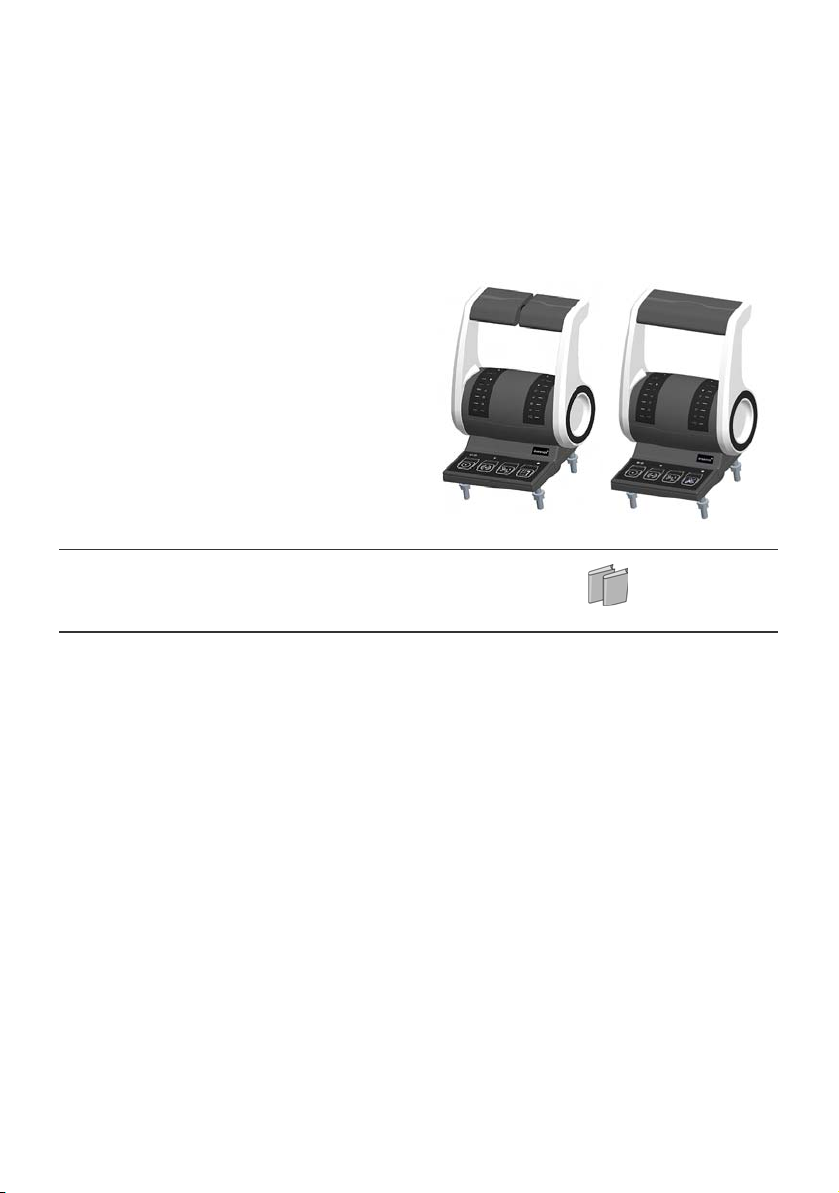
Assembly instructions
Control Head Type 500-ECS
Marex ECS
R417002909/06.2016
English
Page 2

Page 3

AVENTICS | ECS Control Head | R417002909–BDL–001–AA 1
Table of Contents
Table of Contents
1 About this documentation ............................................ 3
1.1 Validity of the documentation................................................ 3
1.2 Required and additional documentations.......................... 4
1.3 Presentation of information................................................... 4
1.3.1 Safety messages ..................................................................... 4
1.3.2 Symbols ..................................................................................... 5
1.3.3 Designations ............................................................................. 5
1.3.4 Abbreviations ............................................................................ 6
2 Safety instructions ........................................................ 7
2.1 About this chapter.....................................................................7
2.2 Intended use................................................................................ 7
2.3 Improper use .............................................................................. 8
2.4 Personnel qualifications..........................................................8
2.5 General safety instructions ....................................................9
2.6 Product- and technology-related safety messages......10
2.7 Operator‘s obligations............................................................10
3 General notes regarding property damages and
product damages ........................................................ 11
4 Scope of delivery ......................................................... 12
5 About this product ....................................................... 14
5.1 Performance description ......................................................14
5.2 Product description ................................................................14
5.2.1 Characteristics and features ............................................. 15
5.2.2 Control Head Type 500-ECS - Product views ............... 16
5.2.3 Ports and connections ................................................ 18
5.2.4 Levers ....................................................................................... 18
5.2.5 Keys and functions ................................................................ 21
5.2.6 LEDs and states of operation ............................................. 24
5.3 Wireless LAN-function...........................................................25
5.4 Classification.............................................................................26
5.5 Product identification.............................................................27
6 Transport and storage ................................................ 28
6.1 Product transport....................................................................28
6.2 Delivery check ..........................................................................28
6.3 Product storage .......................................................................29
English
Page 4

2 AVENTICS | ECS Control Head | R417002909–BDL–001–AA
Table of Contents
7 Assembly ..................................................................... 30
7.1 Installation conditions............................................................31
7.1.1 Mounting orientation ............................................................ 32
7.2 Connecting the control head ................................................32
7.2.1 Connecting the control head to the Marex ECS Control
Unit ............................................................................................ 34
8 Commissioning ............................................................ 36
8.1 Carrying out the auto-configuration ..................................36
8.2 Connecting to the MarexLink network ..............................39
9 Maintenance and repair ............................................. 41
9.1 Cleaning......................................................................................41
9.2 Inspection...................................................................................41
9.3 Maintenance..............................................................................41
10 Disassembly and replacement .................................. 42
11 Disposal ....................................................................... 43
12 Error search and troubleshooting ............................ 44
13 Technical data ............................................................. 46
14 Accessories ................................................................. 47
15 Appendix ...................................................................... 49
15.1 Installation drawings..............................................................49
15.1.1 Control Head Type500-ECS-single .................................. 49
15.1.2 Control Head Type500-ECS-twin ...................................... 50
16 Alphabetical Index ...................................................... 51
Page 5

AVENTICS | ECS Control Head | R417002909–BDL–001–AA 3
About this documentation
1 About this documentation
1.1 Validity of the documentation
These assembly instructions apply to the following versions of
Control Head Type 500-ECS for single and twin propulsion
systems:
Tab le 1: Do cu me nt val id it y
Product No.
Single versions
R417002881 R417002880 Chrome-plated
R417002810 R417002808 Black
R417002891 R417002890 Customer version
R417002871 R417002870 Customer version
The Control Head Type 500-ECS is part of the Marex ECS ship
control system.
Unless otherwise stated in this documentation, the designation
"control head" applies for all product versions single and twin.
The illustrations in this document are examples only and can
differ from the appearance of the actual product.
In context which refers to the ship’s direction of thrust, ’forward’
is used as equivalent term for ’ahead’ and ’reverse’ for ’astern’.
These assembly instructions are intended for mechanics and
service technicians.
These assembly instructions contain important information for
properly and safely installing, starting up, maintaining and
dismantling the Control Head Type 500-ECS.
O Read these assembly instructions completely, especially the
chapter 2, Safety instructions, before working with the
product.
Product No.
Twin versions
Description
English
Page 6

4 AVENTICS | ECS Control Head | R417002909–BDL–001–AA
About this documentation
1.2 Required and additional documentations
Before powering up the product, make sure to read and
understand the necessary documents
O Observe the instructions for the other system components.
O Observe the boat’s operating instructions.
Table 2: Required and additional documentations
Tite l Document No. Document Type
Marex ECS R419302113 Quick guide
1.3 Presentation of information
For a quick start and safe operation of the product, consistent
symbols, terms and abbreviations are used and safety
instructions are given in a consistent manner. For easy
understanding, explanations are provided in the following
sections.
1.3.1 Safety messages
This documentation includes safety instructions placed before a
sequence of actions during which there is a risk of damage to
persons or property. The precautions described must be
observed.
Safety instructions are structured as follows:
SIGNALWORD
Type and source of risk
Consequences
O Precautions
W Warning sign: Draws attention to the risk
W Signal word: Identifies the hazard level
W Type and source of risk: Identifies the type and source of the
hazard
Page 7

AVENTICS | ECS Control Head | R417002909–BDL–001–AA 5
About this documentation
W Consequences: Describes the consequences of non-
observance
W Prevention: Describes how to avert the danger
Table 3: Hazard classes according to ANSI Z535.6-2006
Warningsign, signal word Meaning
Indicates a hazardous situation
DANGER
WARNING
CAUTION
NOTICE
which, if not avoided, will result in
death or serious injury
Indicates a hazardous situation
which, if not avoided, could result in
death or serious injury.
Indicates a hazardous situation
which, if not avoided, could result in
minor or moderate injury.
Property damage: The product or the
environment may be damaged.
1.3.2 Symbols
The following symbols mark notices which are not relevant to
safety but contain useful knowledge for the proper operation of
the product.
Table 4: Meaning of symbols
Symbol Meaning
If this information is not observed, the optimal use or
operation of the product cannot be ensured.
O
1.
2.
3.
Single, independent step
Numbered instructions:
The numbers indicate the steps which must be executed
in a given order.
1.3.3 Designations
The following designations are used in this documentation:
English
Page 8

6 AVENTICS | ECS Control Head | R417002909–BDL–001–AA
About this documentation
Tab le 5: De si gna ti on s
Designation Meaning
Marex ECS Marex Easy Control System
MarexLink Wireless network tool to modify
1.3.4 Abbreviations
The following abbreviations are used in these assembly
instructions:
Table 6: Abbreviations
Abbreviation Meaning
CAN Controller Area Network
Asynchronous serial bus system for the networking of
control units
WLAN Wireless Local Area Network
GL Germanischer Lloyd
Classification society based in Hamburg, Germany
Single Control head for single engine systems
Twin Control head for twin engine systems
PORT portside
STBD starboard
(electronic ship remote control
system)
the settings of Marex ECS using
mobile devices.
Page 9

AVENTICS | ECS Control Head | R417002909–BDL–001–AA 7
Safety instructions
2 Safety instructions
2.1 About this chapter
The control head has been manufactured in strict compliance
with the generally accepted rules of technology. However, this
does not exclude the risk of damage to persons or property if the
general safety instructions in this chapter and the safety
instructions in this document are not observed.
O Read these assembly instructions completely and carefully
before starting to operate the control head.
O Keep these assembly instructions in a location where they
are accessible to all users at any time.
O Always include these assembly instructions when passing
the control head on to third parties.
2.2 Intended use
The control head is used to control ship propulsion systems. It
is designed for in- or outdoor application on small boats, yachts
or small commercial vessels.
The control head may only be used with Marex ECS under the
conditions described in these assembly instructions.
W The control heads described in this document cannot be
combined with the components of the first generation
MarexECS:
R417002550
R417002400
R419302102
R417002102
R417002103
A separate emergency stop switch must be provided on every
control station.
English
Page 10

8 AVENTICS | ECS Control Head | R417002909–BDL–001–AA
Safety instructions
W Comply with the operating conditions and performance
limits stated in chapter 12, Technical data.
Intended use includes having fully read and understood this
manual and especially chapter 2, Safety instructions.
2.3 Improper use
Any use other than as described in "Intended use" is improper
and thus inadmissible.
If, in applications relevant to safety, inappropriate products are
installed or used, unintended operating conditions can be
created in the application which may cause damage to persons
and/or property. Therefore only apply a product within
applications relevant to safety if this kind of use is clearly
specified and permitted in the product's documentation as for
example within explosive areas or in parts of a control system
which are relevant for functional safety.
Unintended use of the product does also include:
W connecting the Marex ECS Control Head to inadmissible
supply voltage (see chapter 13, Technical data),
W combining the Marex ECS Control Head with further
components which are not suitable for that purpose,
W exposing the Marex ECS Control Head to ambient conditions
which are not admissible (see chapter 13, Technical data).
AVENTICS GmbH declines any responsibility for damage
resulting from unintended use. The user of the equipment is
fully responsible for any risk arising from unintended use of the
product.
2.4 Personnel qualifications
The activities described in these assembly instructions require
basic knowledge of electronics and the corresponding
terminology. To ensure the safe use of the product, those
Page 11

AVENTICS | ECS Control Head | R417002909–BDL–001–AA 9
Safety instructions
activities may only be performed by authorized personnel or by
instructed persons supervised by authorized personnel.
An authorized person is someone who due to his/her expert
training, knowledge and experience including his/her
knowledge of the relevant regulations can assess the assigned
tasks, recognize possible dangers and take appropriate safety
measures. Authorized personnel must comply with the
applicable specialist regulations.
The Control Head Type 500-ECS must only be operated by
persons who are familiar with its function and the control
system.
2.5 General safety instructions
W Observe the valid regulations pertaining to accident
prevention and environmental protection
W Observe the safety instructions and guidelines of the
country in which the product is used.
W Only use AVENTICS products in technically perfect condition.
W Check the product for obvious defects as for example cracks
in the housing or missing screws, caps or sealings.
W You must not modify or convert the control head.
W Persons who install, operate, dismantle or maintain
AVENTICS products must not be under the influence of
alcohol, other drugs or medications which affect the
responsiveness.
W Make sure that safety devices belonging to the product are
available, properly installed and fully operational. Such
safety devices must not be relocated, bypassed or rendered
ineffective.
W If safety devices are taken out of operation in order to work
on the product you must make sure that no risk arises for
persons or property. Observe the additional
documentations.
W Warranty applies exclusively for the configuration supplied.
W Incorrect assembly, unintended use or inappropriate
handling will invalidate the warranty.
English
Page 12

10 AVENTICS | ECS Control Head | R417002909–BDL–001–AA
Safety instructions
W Under no circumstances the product may be subjected to
mechanical load. Never use the product as a handle or step.
Do not place objects on the product.
2.6 Product- and technology-related safety
messages
Assembly O Always disconnect the system from the power supply before
assembling the control head, connecting or disconnecting
plugs. Secure the system against being switched on
unintentionally.
O Lay cables in such a way that they cannot be damaged and
nobody can trip over them.
O Before starting the product make sure that all seals and
protective caps on connectors are properly fixed and
undamaged in order to prevent that liquids and foreign
particles penetrate into the product.
Commissioning O Make sure that all electric ports are used or covered. Only
start up products which are fully installed.
Operation O Only allow authorized persons to access the helm.
2.7 Operator‘s obligations
Installation and maintenance work is subject to the countryspecific safety regulations and standards of the application. As
an operator of a ship which shall be equipped with a Marex ECS
Control Head and further components of a ship remote control
system, you are responsible that
W the product is in technically perfect condition,
W the product is used as intended,
W any staff handling the product has read and understood the
documentation,
W users of the product are trained and instructed,
W the regulations related to safety, accident prevention and
environmental protection are complied with.
Page 13

AVENTICS | ECS Control Head | R417002909–BDL–001–AA 11
General notes regarding property damages and product damages
3 General notes regarding
property damages and product
damages
Cleaning O Cover all openings with suitable protective caps to prevent
that cleaning agent penetrates into the system.
O Never use solvents or other aggressive cleaners. Clean the
product only by using a slightly moistened lint-free cloth.
Only use water or mild cleaning agents.
O Never use pressure washers or steam cleaners to clean the
product.
Disposal O Dispose of the product according to national provisions of
your country.
English
Page 14
12 AVENTICS | ECS Control Head | R417002909–BDL–001–AA
Scope of delivery
4 Scope of delivery
The standard product delivery includes:
Table 7: Standard product delivery
1 Control Head Type 500-ECS, in one of the
following product versions:
R417002881, chrome-plated, single
R417002880, chrome-plated, twin
R417002810, black, single
R417002808, black, twin
R417002891, customer version, single
R417002890, customer version, twin
R417002871, customer version, single
R417002870, customer version, twin
1 Assembly instructions
Page 15

AVENTICS | ECS Control Head | R417002909–BDL–001–AA 13
Scope of delivery
For the assembly:
1 Drilling template
4Nuts M6
4Washers 6.4
English
Page 16

14 AVENTICS | ECS Control Head | R417002909–BDL–001–AA
About this product
5 About this product
5.1 Performance description
The control head actuates the throttle and gear box of the boat’s
propulsion system including related special functions such as
speed synchronization.
In addition, the control head provides keys and LEDs to take the
command over and signal and acknowledge malfunctions.
The component includes a wireless LAN-module which permits
a wireless information exchange with other devices.
The control head is a component of Marex ECS. Depending
on the software some of the functions which are described
in these assembly instructions may not be supported.
5.2 Product description
All versions of the Control Head Type 500-ECS are available for
single and twin engine operation. Single and twin versions have
basically the same design.There is only a minor difference in the
levers and the key assignment.
Furthermore, there are the following versions of the Control
Head Type 500-ECS which differ in the appearance and scale
illumination.
W R417002881, chrome-plated, single
W R417002880, chrome-plated, twin
W R417002810, black, single
W R417002808, black, twin
W R417002891, special, single
W R417002890, special, twin
W R417002871, special, single
W R417002870, special, twin
Page 17

AVENTICS | ECS Control Head | R417002909–BDL–001–AA 15
About this product
With the single control head version, the levers form one handle
which - when moved- transmits only one signal to control
throttle and gearbox.
The twin control head version provides two levers each of which
is used to actuate independently of the other the throttle and
transmission direction of one propulsion side, port or starboard.
It is possible to synchronize the speeds of the port and
starboard engines automatically by pressing a corresponding
key.
5.2.1 Characteristics and features
W All parts weather resistant and protected against water
ingress
W Bottom and body made of fibre-reinforced high-
performance synthetics, black
W Contactless detection of the lever’s position, sensor
redundancy provided
W Keys and device status LEDs on keypad with background
illumination and automatic light level control through
integrated brightness sensor
W Signal processing via CAN bus
W One M12 connector for power supply and CAN bus
W One microprocessor for starboard and portside
W Integrated wireless LAN-module for data exchange with
other devices
English
Tabelle 8: Variant-specific features
Variant Lever design Scale illumination
R417002808, R417002870
R417002810, R417002871
Fibre-reinforced high-
performance synthetics,
None
black
R417002880, R417002890
R417002881, R417002891
Aluminum, chromeplated
Illuminated scale with automatic
light level control, operator
guidance by highlighting relevant
scale segments
Page 18

16 AVENTICS | ECS Control Head | R417002909–BDL–001–AA
1
2
3
4
About this product
5.2.2 Control Head Type 500-ECS - Product views
Fig. 1: Overview Control Head Type 500-ECS-single
1 Lever
2 Indicator
3 Scale
4 Keypad
Page 19

AVENTICS | ECS Control Head | R417002909–BDL–001–AA 17
2
3
4
1
Port
STBD
1
About this product
Fig. 2: Overview Control Head Type 500-ECS-twin
1 Levers
English
2 Indicator
3 Scale
4 Keypad
Page 20

18 AVENTICS | ECS Control Head | R417002909–BDL–001–AA
6
5
9
7
8
6
About this product
5.2.3 Ports and connections
The following figure shows the bottom of the control head:
Fig. 3: Control head, bottom view
5 Ventilaton 8 Nut and washer
6 STATION socket 9 Sealing
7 Mounting bolt
Single The Control Head Type500-ECS-single provides one lever to
Twi n The Control Head Type 500-ECS-twin provides two levers to
5.2.4 Levers
actuate the throttle and transmission direction.
actuate the throttle and transmission direction of each
propulsion system. The left lever operates the portside engine
and gearbox, the right lever operates the starboard engine and
gearbox.
With both versions, twin and single, the levers can be stationed
in any position over the complete adjusting range. In addition,
they engage perceptibly in the following positions:
Page 21

AVENTICS | ECS Control Head | R417002909–BDL–001–AA 19
About this product
Lever position NEUTRAL The gearbox is disengaged, MIN RPM are set.
Lever position FORWARD The gearbox is engaged to FORWARD, MIN RPM or a speed
corresponding to the RPM curve is set.
Lever position REVERSE The gearbox is engaged to REVERSE, MIN RPM or a speed
corresponding to the RPM curve is set.
In normal operation, the RPM are evenly adjusted from
minimum to the set speed in a linear way when the lever is
moved between the positions FORWARD SLOW and FORWARD
and REVERSE SLOW and REVERSE. Depending on the
configuration of Marex ECS, it is possible to set other RPM
curves which will be available temporarily or permanently. The
transmission direction remains unchanged.
Notice Your Marex ECS may include a special or extra function. In that
case, the throttle and gearbox settings may differ from the
above description.
English
Page 22

20 AVENTICS | ECS Control Head | R417002909–BDL–001–AA
About this product
Lever positions
NEUTRAL positon,
gearbox disengaged
FORWARD SLOW position,
gearbox engaged to forward
FORWARD position,
maximum RPM
Fig. 4: Control head, lever positions
REVERSE SLOW position,
gearbox engaged to reverse
REVERSE position,
maximum RPM
Page 23

AVENTICS | ECS Control Head | R417002909–BDL–001–AA 21
About this product
5.2.5 Keys and functions
In the following section you will find figures depicting the
keypads of Control Head Type 500-ECS, single and twin. Keys
and LEDs are shown and explained.
Notice This chapter gives an overview on the standard functions. The
functions of your control head may be different from what is
described as they depend on the configuration of your Marex
ECS and its settings.
English
Page 24

22 AVENTICS | ECS Control Head | R417002909–BDL–001–AA
4
1
23
5
6
1
2
3
4
5
6
About this product
Operating elements on Control Head Type 500-ECS:
Fig. 5: Keypad Control Head Type 500-ECS single
Fig. 6: Keypad Control Head Type 500-ECS-twin
1 COMMAND key with COMMAND LED(s)
2 ALARM key with ALARM LED(s)
3 SLOW MODE key with SLOW MODE LED(s)
4 WARMING UP key with WARMING UP LED (single)
SYNCHRO key with SYNCHRO LEDs (twin)
5 Device status LED
6 Brightness sensor
Page 25

AVENTICS | ECS Control Head | R417002909–BDL–001–AA 23
Table 9: Keys and functions of Control Head Type 500-ECS
Element Designation Function
COMMAND key with
COMMAND LED(s)
1. Request command
(1)
2. Take the command over
3. Warm engine up (twin): Controlling the engines without
engaging the clutch.
About this product
ALARM key
SLOW MODE key
WARMING UP key
(single)
SYNCHRO key
(twin)
(2) 1. Acknowledge alarm
(4)
2. Switch acoustic alarm signal off
3. Activate wireless LAN
(3) Adjust propeller RPM depending on system configuration:
W Switch over to alternative rpm curve
(4)
Warm the engine up: Controlling the engine RPM without
engaging the clutch
Control both engines with the starboard lever. The same RPM
are set for both propulsion engines.
English
Page 26

24 AVENTICS | ECS Control Head | R417002909–BDL–001–AA
About this product
5.2.6 LEDs and states of operation
The control head provides LEDs in different colors for a
comprehensive overview on the control’s function.Three states
of operation must be distinguished:
1. LED is permanently lit.
2. LED flashes.
3. LED is off.
Table 10: LED states, overview
Station not in
COMMAND
(passive)
no ALARM ALARM
Station in
COMMAND
(active)
pending,
acknowledged
COMMAND
requested
(+ buzzer)
or
WARMING UP
(twin)
ALARM
pending, not
yet
acknowledged
SLOW MODE
off
SYNCHRO off
(twin)
WARMING UP
off (single)
SLOW MODE
on
SYNCHRO on
(twin)
WARMING UP
on (single)
Page 27
AVENTICS | ECS Control Head | R417002909–BDL–001–AA 25
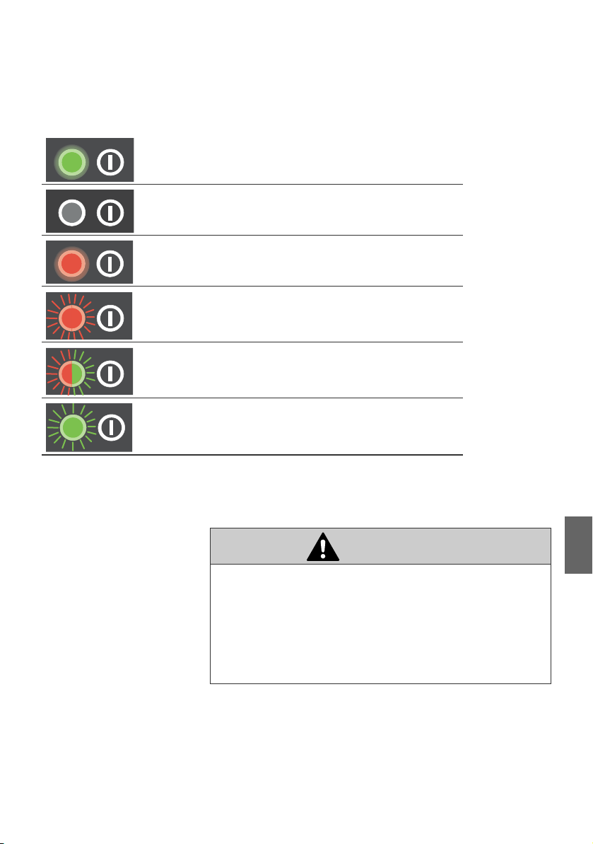
Device status LED
Table 11: States of the device status LED
The control head is ready for operation.
The control head is not operational.
The control head is defective.
The control head has not been configured yet or the
auto-config has been aborted.
Auto-config is running. The LED flashes alternately red
and green.
As soon as the auto-config is finished, the LED flashes
green.
About this product
5.3 Wireless LAN-function
CAUTION
Risk of damage to persons and property when settings are
changed during navigation
Changing control settings while the ship is in motion can lead
to navigation errors and cause accidents.
O Never change Marex ECS settings while the ship is
moving.
The control head has an integrated wireless LAN-interface
which allows you to connect to the MarexLink webserver and
set up your Marex ECS comfortably using your smartphone or
tablet computer.
English
Page 28

26 AVENTICS | ECS Control Head | R417002909–BDL–001–AA
About this product
The range of the integrated wireless LAN-module is 3 to 5m
approximately. However, the boat’s sides, partitions etc. may
affect the operating range. You can use any mobile device which
provides a WLAN-interface and HTML5-compatible internet
browser to set up a connection. Internet is not necessary to
access MarexLink. As soon as you are connected to the
MarexLink webserver, you can view or change the settings of
your Marex ECS ship control.
Notice It depends on the version and configuration of your Marex ECS
which settings are available in MarexLink.
5.4 Classification
The Control Head Type 500-ECS has been designed and
manufactured in compliance with the generally accepted rules
of technology. It was tested in accordance to the following rules
and guidelines and fulfills the requirements stipulated therein:
Germanischer Lloyd (GL) O Rules for Classification and Construction IV Part 7 Chapter 2,
Test Requirements for Electrical / Electronic Equipment and
Systems, Edition 09/2012
O Environmental Categories C and F
DIN EN ISO 25197 O "Kleine Wasserfahrzeuge - Elektrische/elektronische
Regelsysteme für Steuerung, Schaltung und Antrieb,
Ausgabe 03/2015
Regulations of American
Boat and Yacht Council
(ABYC)
O ABYC-Standard P24 "Electric / Electronic Propulsion Control
Systems", issue 2007
Page 29
AVENTICS | ECS Control Head | R417002909–BDL–001–AA 27
1
2
3
4
5
About this product
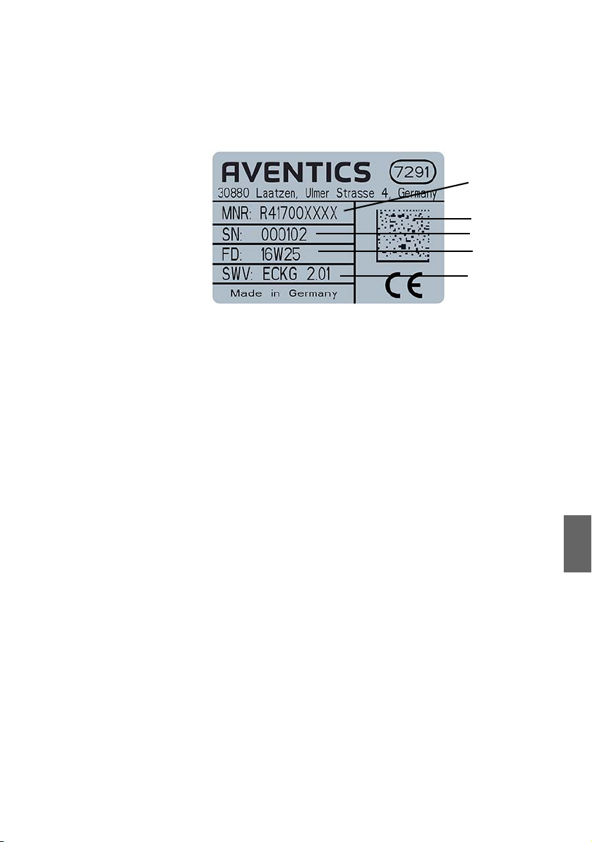
5.5 Product identification
Fig. 7: Type plate Control Head Type 500-ECS, example
1 Material number
2 QR-Code
3 Serial number
4 Date of production
5 Software-Version
English
Page 30

28 AVENTICS | ECS Control Head | R417002909–BDL–001–AA
Transport and storage
6 Transport and storage
6.1 Product transport
NOTICE
Damage due to improper transport
Improper transport can cause substantial material damage.
O Be careful when unloading the packages on delivery and
in case of in-plant transport. Observe the symbols and
instructions on the package.
O Only remove the ESD-packaging shortly before mounting
the wiring harness.
Tests have proven the seaworthiness of Control Head Type 500ECS. Therefore no particular instructions must be observed
during transport.
6.2 Delivery check
O Check the supply immediately on receipt for completeness
and transport damage.
O Proceed as follows if any visible damage is discovered
during receipt of delivery:
O Do not accept the delivery or only under reservation.
O Note the extent of damage on the transportation documents
or the delivery note.
O Submit a claim.
Page 31

AVENTICS | ECS Control Head | R417002909–BDL–001–AA 29
Transport and storage
6.3 Product storage
Do not destroy the packaging and only remove it shortly before
installation. Adhere to the following conditions for storage:
O Store the control head in its original packaging.
O Do not store packages outside.
O Store the packages in a dry and dust-free place.
O Do not expose the packages to aggressive media.
O Protect the packages against solar radiation.
O Observe the maximum storage period for electronic
components, see also chapter 12, Technical data.
O Make sure that all M12-protective caps are attached. This
will guarantee protection class IP 66.
O Observe the admissible storage temperature of -40C to
85C.
English
Page 32

30 AVENTICS | ECS Control Head | R417002909–BDL–001–AA
Assembly
7 Assembly
NOTICE
Property damage due to improper installation or mounting
work
Improper installation can cause damage to property.
O The Marex ECS Control Head may only be installed by
AVENTICS or qualified personnel as specified in chapter
2.4.
O Install or uninstall the Marex ECS Control Head only if the
component and the system are powered off.
O Prepare mounting work carefully.
O Make sure there is enough space to mount the product
professionally.
The control head is designed for console or panel installation. At
first, provide the necessary panel cutout as shown in fig. 8:
1. For the mounting bolts, drill 4 holes with a diameter of
6.5mm.
2. Prepare a circular cutout into which the electrical
connections can be inserted. For metric tools, the size of the
diameter is 68 mm at maximum. For inch tools, a wider
diameter is admissible up to a maximum of 85 mm if the
center of the bore is moved downwards by 8 mm at
maximum.
A drilling template is included in the delivery.
Page 33

AVENTICS | ECS Control Head | R417002909–BDL–001–AA 31
Assembly
Fig. 8: Drilling template for installation (mm)
7.1 Installation conditions
The following installation conditions must be observed:
W The mounting bolts are suitable for a panel thickness
between 2 to 20 mm.
W The mounting depth for the electric plugs and connections
below the console or panel is 140 mm approximately.
W Install the control head in such a way that the levers’ moving
range is not restricted by other components and all
operating and indicating elements are visible and can be
easily operated at all times.
W A circumferential sealing is provided around the Control
Head Type 500-ECS to seal its edge to the panel surface.
Make sure that no bores or gaps in the panel surface are
located in the sealing area as otherwise the tightness of the
panel can not be guaranteed.
W If you install the control head on panels which are uneven or
have a rough, structured surface, use an elastic sealant in
addition. This will ensure protection class IP 66.
English
Page 34

32 AVENTICS | ECS Control Head | R417002909–BDL–001–AA
6
Assembly
W Use the nuts and washers supplied to mount the Control
Head Type 500-ECS and fix the nuts with a maximum torque
of 2 Nm.
7.1.1 Mounting orientation
Always install the control head in the following sense:
W In cruising direction
W With the levers pointing upwards.
7.2 Connecting the control head
The Control Head Type 500-ECS is connected via M12 plug
connectors which are provided on the bottom side of the
component.
Fig. 9: Electrical connections
Page 35

AVENTICS | ECS Control Head | R417002909–BDL–001–AA 33
The connectors are described in the following table:
Table 12: Electrical connections of the control head
Socket Type Color
6 STATION
6 STATION
M12
5-pin male
M12
5-pin male
grey yes Connection to the STATION cable of
grey yes Connection to another control head
Connection
required
The connectors (6) are identical and can be selected as
preferred.
We recommend only to use cables which are approved by
AVENTICS. These ensure
W faultless data transmission
W safe and sealed plug-in connections
W colors matching the connectors
Assembly
Function
the Marex ECS Control Unit
or
terminating resistor
NOTICE
Danger of malfunction if protective caps are not applied
If protective caps are not applied, humidity and foreign
particles can penetrate into the component and cause
malfunction. In addition, the protection class may be lost.
O Cover all connectors which are not required with the
corresponding protective caps supplied.
English
Page 36

34 AVENTICS | ECS Control Head | R417002909–BDL–001–AA
Assembly
7.2.1 Connecting the control head to the Marex ECS
Control Unit
NOTICE
Material damage due to incorrect supply voltage
Supplying the Control Head Type 500-ECS with power from
outside the remote control system can cause a failure of the
component. Then the ship’s speed can no longer be controlled.
O Only use the system’s internal power supply via the
STATION bus cable to supply the Control Head Type 500ECS with power.
Use one of the STATION sockets ((6), fig. 9), to connect the
control head to the Marex ECS control unit.
1. Make sure that the power is switched off. Connect the
STATION bus cable coming from the Marex ECS Control Unit
to one of the STATION sockets ((6), fig. 9).
Via this cable
– digital data is transmitted by means of a CAN bus protocol
and
– the component is supplied with power.
If Marex ECS includes more than one control head, only the
first Control Head Type 500-ECS is connected directly to the
Marex ECS Control Unit.
2. Connect optional control heads to the second STATION
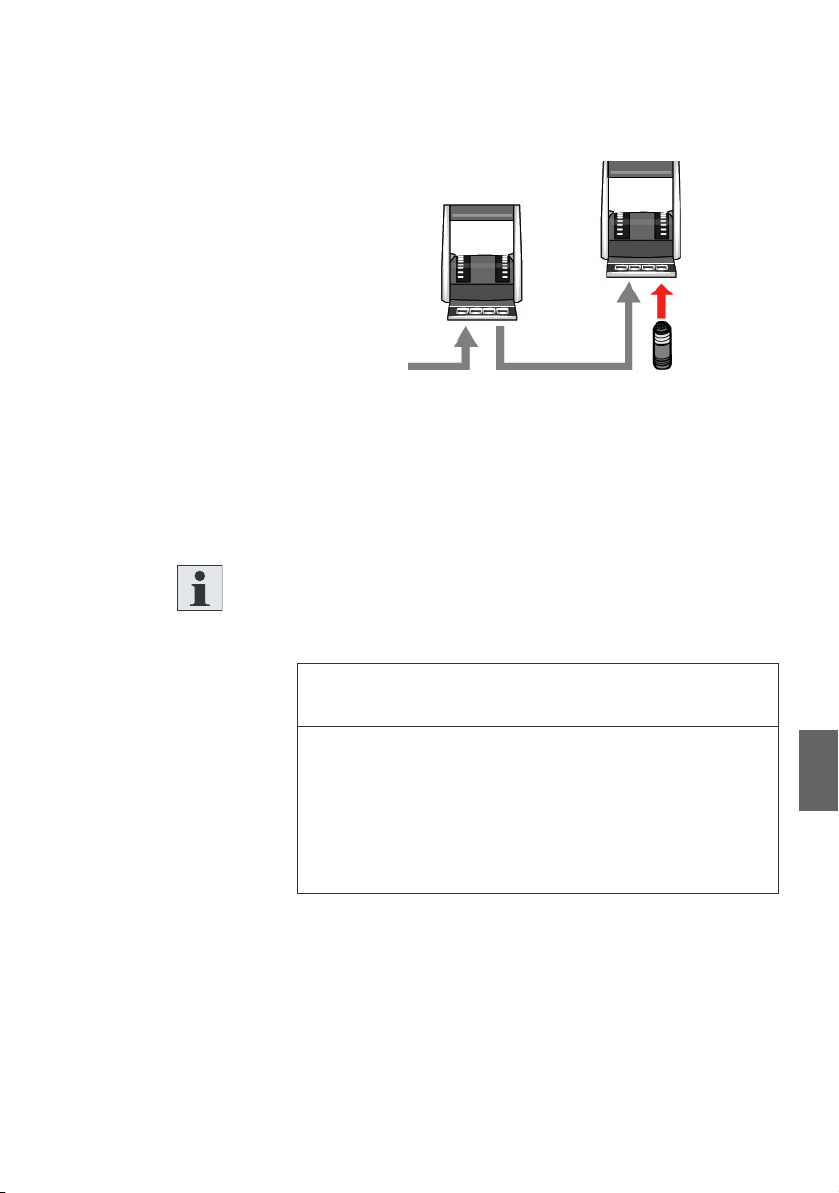
socket (6) of the preceding control head.
– Apply a terminating resistor on the second STATION
socket ((6), fig. 9)), if no other control head shall be
connected. On every control head both STATION sockets
must be always be occupied (see also fig. 10).
Page 37
AVENTICS | ECS Control Head | R417002909–BDL–001–AA 35
Assembly
Fig. 10: Control head with terminating resistor
Maximum length
STATION cable
Installation order of the
control heads
O Up to 4 control heads can be included in Marex ECS. The
maximum length of the STATION cable is 30 m with 12Vsystems and 60m with 24 V-systems.
O Several Control Heads Type 500-ECS can be connected in
any order.
Define the control head which is best accessible as the first
component and keep the cable lengths as short as possible.
NOTICE
Material damage due to unapplied terminating resistor
If the terminating resistor is not applied, the data
transmission can be disturbed. Then the ship’s speed can no
longer be controlled.
O Make sure that all required terminating resistors are
correctly applied.
Terminating resistor The terminating resistor is screwed on the STATION connector
of the Marex ECS wiring harness.
O Remove the terminating resistor to connect components to
the STATION cable.
O Reattach the terminating resistor on the last STATION
participant after having connected all components to the
STATION bus (see also fig. 10).
English
Page 38

36 AVENTICS | ECS Control Head | R417002909–BDL–001–AA
Commissioning
8 Commissioning
The Control Head Type 500-ECS may only be used with the
Marex ECS remote control system. Marex ECS must be autoconfigured and tested before starting the operation.
8.1 Carrying out the auto-configuration
Auto-config Marex ECS features automatic configuration (auto-config). Only
few steps are required to log on and configure components.
Always perform those steps,
W if you have installed a new Marex ECS,
W if you have replaced a control head,
W if you have enhanced the system and added another control
head,
W if you have removed and reinstalled a control head.
Fig. 11: Marex ECS Wiring Harness with auto-config connector
Page 39

AVENTICS | ECS Control Head | R417002909–BDL–001–AA 37
Commissioning
Proceed as follows to start the auto-config:
1. Power Marex ECS completely off.
2. Install the Control Head Type 500-ECS and establish the
electrical connections as described on page 30, Assembly.
3. Disconnect the auto-config plug from the Marex ECS Wiring
Harness as shown in fig. 12.
Fig. 12: Disconnect the auto-config plug
4. Switch the power supply on.
The auto-config is running. The process may take a few
minutes.The control head is being registered and
configured with standard settings. The device status LEDs
flash alternately red and green on all Marex ECS
components.
When the LEDs flash green on all components, the autoconfig is finished.
English
Page 40

38 AVENTICS | ECS Control Head | R417002909–BDL–001–AA
Commissioning
5. Reattach the Autoconfig-connector to the corresponding
jack on the wiring harness (fig. 13). Make sure the connector
fits securely.
Fig. 13: Reattach the autoconfig-connector
The configuration is complete.The device status LEDs are
indicating the components‘ status again.
If you wish to modify settings you can now make the necessary
changes using the wireless MarexLink network (see 8.2.)
6. Test all system functions first at standstill and later at slow
speed.
The commissioning is completed if all functions are working
without failure.
Repeat the auto-configuration if the process is interrupted or
red LEDs flash or light up permanently.
Page 41
AVENTICS | ECS Control Head | R417002909–BDL–001–AA 39
Commissioning
8.2 Connecting to the MarexLink network
If you wish to view or modify the settings of your Marex ECS, you
can easily connect to the MarexLink network by using your
mobile device such as a smartphone or tablet computer.
CAUTION
Risk of damage to persons and property when settings are
changed during navigation
Changing settings when the boat is in motion can lead to
navigation errors and cause accidents,
O Always set the control head lever(s) in NEUTRAL position
before changing control settings.
O Never change control settings when the ship is in motion.
1. Push the ALARM key on the control head‘s key pad (see fig.
5 and 6) for at least 5 s. As soon as you hear a short buzzer
signal, the WLAN is on.
2. Connect your mobile device to the Marex ECS MarexLink
network. You are prompted to enter a password.
3. Enter "marexecs". Your mobile device confirms that the
network connection has successfully been set up.
If not used, the WLAN switches off automatically after
10 minutes. To switch the WLAN off manually, push the
ALARM-key again for more than 5 s. As soon as you hear a
long buzzer sound, the WLAN is off.
English
Page 42

40 AVENTICS | ECS Control Head | R417002909–BDL–001–AA
Commissioning
To access MarexLink, open the webbrowser and enter the IPaddress http://192.168.10.1:8080 in its address bar.
Alternatively, scan the following QR code:
Your webbrowser must be HTML5-compatible to access
MarexLink.
For further information how to log on MarexLink and change the
settings of your Marex ECS, use the help buttons provided within
MarexLink.
Page 43

AVENTICS | ECS Control Head | R417002909–BDL–001–AA 41
Maintenance and repair
9 Maintenance and repair
9.1 Cleaning
NOTICE
Product damage due to inappropriate cleaning
Cleaning agents containing solvents may damage the
product's surface and cause premature aging.
O Do only use solvent-free, non-abrasive cleaning agents
O Never use pressure washers or steam cleaners to clean
the Control Head Type 500-ECS.
Clean the product only by using a slightly moistened, lint-free
cloth. Only use water or mild cleaning agents.
9.2 Inspection
Make sure the component is always in technically perfect
condition. Check the Control Head Type 500-ECS regularly for
visual damage, especially for possible defects on keypad and
displays and missing sealings or covers.
9.3 Maintenance
The control head does not require maintenance.
Notice Do not attempt to repair a damaged control head yourself. In
case of defects, always replace the complete control head.
English
Page 44

42 AVENTICS | ECS Control Head | R417002909–BDL–001–AA
Disassembly and replacement
10 Disassembly and replacement
CAUTION
Injury hazard and material damage due to unmaneuverable
ship
If you dismantle or replace the Control Head Type 500-ECS
while the ship is moving, the ability to steer may be lost.
O Only dismantle the control head if the ship is not in
operation.
NOTICE
Material damage due to applied supply voltage
Attaching and removing plugs and connectors under power
can destroy the component.
O Only perform assembly or disassembly work on
electrical connections if components and cables are
powered off.
Proceed as follows to dismantle the Control Head Type 500ECS:
1. Switch Marex ECS off.
2. Make sure the Control Head Type 500-ECS is powered off.
3. Remove the electrical connections (see also fig. 3 on page
18).
4. Loosen the mounting nuts. You may now remove the Control
Head Type 500-ECS.
Page 45

AVENTICS | ECS Control Head | R417002909–BDL–001–AA 43
Disposal
11 Disposal
NOTICE
Environmental damage due to improper disposal
Electronic components require special waste treatment and
must only be disposed of by approved specialist companies.
O Dispose of electronic scrap in an environmentally sound
way. Consult the responsible local authorities regarding
the environmentally sound disposal.
Dispose of the packaging in an environmentally compatible way.
English
Page 46

44 AVENTICS | ECS Control Head | R417002909–BDL–001–AA
Error search and troubleshooting
12 Error search and
troubleshooting
Malfunctions are signaled to the operator by the ALARM LEDs
and the device status LEDs on the control head’s keypad (see
also chapters 5.2.5 and 5.2.6.).
WARNING
Hazard of a fatal accident or collision due to a system
failure
When ALARM LEDs flash red or light up permanently this
indicates a device failure or malfunction which may result in
a system failure or even unexpected reaction of the boat.
You may no longer be able to control the main propulsion
engine. To prevent a fatal accident or collision, immediately
take the following measures when the ALARM LED flashes
or lights up:
O First bring the boat into a safe state!
O Only then acknowledge the alarm and eliminate the
cause of the fault
If the active control head fails, Marex ECS automatically reduces
the engine rpm to idle and disengages the clutch.
O In case of malfunctions, check the LEDs on the control
head(s) and carry out the corresponding steps as explained
in the following table:
Page 47

AVENTICS | ECS Control Head | R417002909–BDL–001–AA 45
Table 13: LED indications on the control head
LED-signal Meaning What to do
This control head is defective.
O Replace the control head and repeat the
auto-configuration (see also chapters
8.1 and 10).
O If available, check also the function of
the other control heads by comparing
the LED signals and referring to the
instructions in this table.
O If available, check the function of the
optional actuator(s). Refer to the
Marex ECS Quick guide and the
actuator’s assembly instructions.
This control head works fine,
but another system component
is defective.
O If available, check the function of the
other control heads, by comparing the
LED signals and referring to the
instructions in this table.
O If available, check the function of the
optional actuator(s). Refer to the
Marex ECS Quick guide and the
actuator’s assembly instructions.
The communication of the
control head has failed or the
power supply is beyond the
admissible range.
Do you still have the command and can control
engine and gear?
O Check the on-board power supply.
If not,
O check the STATION cables, see also
chapter 7.2)
Error search and troubleshooting
English
Power supply failure.
O Check the power supply. See chapter
7.2. Refer also to the
Marex ECS Quick Guide.
Page 48

46 AVENTICS | ECS Control Head | R417002909–BDL–001–AA
Technical data
13 Technical data
Tab le 14 : Tec hn ical d at a
Dimensions
width x height x depth 125 x 154 x 123 mm
Weight 1kg approximately
Power supply 12V DC (-25%/+30%)
Admissible ambient
temperature
Storage temperature 233 to 358 K (-40C to 85 C)
Protection class IP 66 - EN 60529 (IEC 60529)
Vibration resistance Range 2-13 Hz: ± 1.6 mm
Shock resistance 10g/11ms
Rel. humidity 5% - 98% incl. condensation
Material of body PBT/PET, black
Material of lever(s) Variant-specific:
24V DC (-25%/+ 30%)
(internal system power supply via Marex ECS
control unit)
248 to 350 K (-25C to 77°C)
Range 13-100 Hz: ± 4g
Aluminum, chrome-plated or
PBT/PET, black
Page 49

AVENTICS | ECS Control Head | R417002909–BDL–001–AA 47
Accessories
14 Accessories
Part Material No.
Cables
POWER cable, 5m R419801567
POWER cable, 10m (not suitable for Marex ECS Actuators 12 VDC) R419801316
POWER cable, dual battery connection, 5m R419801568
POWER cable, dual battery connection, 10m
(not suitable for Marex ECS Actuators 12V DC)
POWER cable, ignition input, 20m R419801547
GEAR control cable, forward/reverse, 10m R419801334
GEAR control cable, forward/reverse, solenoid valve connector, 5m R419801335
GEAR control cable, forward/reverse, solenoid valve connector, 10m R419801336
THROTTLE control cable, 4 -20 mA, 10m R419801320
THROTTLE control cable, 4- 20 mA, 20m R419801321
THROTTLE control cable, 0 - 5V, 10 m R419801322
THROTTLE control cable, 0 - 5V, 20 m R419801323
THROTTLE control cable, PWM, 10m R419801324
THROTTLE control cable, PWM, 20m R419801325
AUX control cable, start interlock contact, safety stop, high idle, 10m R419801344
AUX control cable, start interlock contact, 10m R419801345
ALARM control cable, alarm and monitoring system interface, 10m R419801319
STATION/PROPULSION bus cable, 1m R419801349
STATION/PROPULSION bus cable, 5m R419801350
STATION/PROPULSION bus cable, 10m R419801351
STATION/PROPULSION bus cable, 15m R419801352
STATION/PROPULSION bus cable, 20m R419801353
STATION/PROPULSION bus cable, 30m R419801354
STATION/PROPULSION bus cable connector, 0.15m R419801362
Wiring harness
Marex ECS single wiring harness R419302201
Marex ECS twin wiring harness R419302202
R419801522
English
Page 50

48 AVENTICS | ECS Control Head | R417002909–BDL–001–AA
Accessories
Part Material No.
Control head
Control head type 500-ECS, single, chrome-plated R417002881
Control head type 500-ECS, twin, chrome-plated R417002880
Control head type 500-ECS, single, black R417002810
Control head type 500-ECS, twin, black R417002808
Control unit
Marex ECS control unit R419302110
Terminating resistor
STATION/PROPULSION bus terminating resistor 8941054274
Actuator
Marex ECS actuator 12 V DC R417002894
Marex ECS actuator 24 V DC R417002895
Page 51

AVENTICS | ECS Control Head | R417002909–BDL–001–AA 49
Appendix
15 Appendix
15.1 Installation drawings
15.1.1 Control Head Type 500-ECS-single
Fig. 14: Dimension drawing Control Head Type 500-ECS, single
English
Page 52

50 AVENTICS | ECS Control Head | R417002909–BDL–001–AA
Appendix
15.1.2 Control Head Type 500-ECS-twin
Fig. 15: Dimension drawing Control Head Type 500-ECS, twin
Page 53

AVENTICS | ECS Control Head | R417002909–BDL–001–AA 51
Alphabetical Index
16 Alphabetical Index
W A
Abbreviations 6
Additional
documentation 4
ALARM control cable 47
Assembly 30
Installation
conditions 31
Mounting orientation 32
Safety instructions 10
Auto-config 36
AUX control cable 47
W C
Characteristics and
features 15
Classification
Germanischer Lloyd 26
Cleaning 11, 41
Commissioning
Safety instructions 10
Configure control head 36
Connect
Marex ECS control
unit 34
Optional components 36
Connect to MarexLink 39
Connections 18
Control head
Characteristics and
features 15
Connect 32
Connect backup control
head 36
Connect optional
components 36
Connect to Marex ECS
control unit 34
Connections 18
Description 14
Device status LED,
Device status LED 25
Dimensions 46
Electrical
connections 32, 33
Keys and functions 23
LED states 24
Lever positions 18, 20
Levers 18
Performance 14
Wireless LAN 25
Control Head Type 500ECS-single
Keys 22
Overview 16
Product description 15
Control Head Type 500ECS-twin
Keys 22
Control unit 47
W D
Delivery
Check 28
Scope 12
Description of control
head 14
Designations 5
Dimensions 46
Dismantle control
English
Page 54

52 AVENTICS | ECS Control Head | R417002909–BDL–001–AA
Alphabetical Index
head 42
Disposal 11
Dispose of control
head 43
Documentation
Abbreviations 6
Designations 5
Required and
additional 4
Symbols 5
Validity 3
W G
GEAR control cable 47
General safety
instructions 9
Germanischer Lloyd 26
W H
Hazard classes ANSI 5
W I
Improper 8
Improper use 8
Installation
Conditions 31
Installation drawing control head single 49
Installation drawing control head twin 50
Intended use 7
IP-address 40
W K
Keys
Control Head Type 500-
ECS-single 22
Control Head Type 500-
ECS-twin 22
Keys and functions 23
W L
LED states 24
Length
STATION bus 35
Lever positions 18, 20
Levers 18
W M
Maintenance 41
Inspection 41
Marex ECS auto-config 36
Marex ECS quick guide 4
MarexLink 25, 39
MarexLink IP-address 40
MarexLink QR-code 40
Material and product damage, notes 11
Mounting depth 31
W O
Operation, safety
instruction 10
Operator’s obligations 10
Order of participants
STATION bus 35
Overview
Control Head Type 500-
ECS-single 16
W P
Panel thickness 31
Performance 14
Personnel
Qualification 8
POWER cable 47
Page 55

AVENTICS | ECS Control Head | R417002909–BDL–001–AA 53
Alphabetical Index
Power supply 46
Product description
Control Head Type 500-
ECS-single 15
Product identification 27
Protection class 46
W Q
QR-code 40
Qualification of
personnel 8
W R
Required
documentation 4
W S
Safety instructions
Assembly 10
Commissioning 10
General 9
Operation 10
Product- and
technology-related 10
Scope of delivery 12
States of the LEDs 24
STATION bus
Maximum length 35
Order of participants 35
Terminating
resistance 35
STATION/PROPULSION
bus cable 47
Storage conditions 29
Power supply 46
Protection class 46
Temperature 46
Temperature, ambient 46
Terminating
resistance 35
Terminating resistor 48
THROTTLE control
cable 47
Transport 28
W U
Use
Improper 8
Intended 7
W V
Validity of
documentation 3
W W
Webserver MarexLink 25,
39
Wireless LAN 25
Wiring harness 47
English
W T
Technical data
Dimensions 46
Page 56

AVENTICS
Ulmer Straße 4
30880 Laatzen, Germany
Phone +49 (0) 511 213 62 51
Fax: +49 (0) 511 213 61 65
www.marex-shipcontrols.com
www.aventics.com
marinesales@aventics.com
The data specified above only serve to
describe the product. No statements
concerning a certain condition or
suitability for a certain application can be
derived from our information. The given
information does not release the user from
the obligation of own judgement and
verification. It must be remembered that
our products are subject to a natural
process of wear and aging.
An example configuration is depicted on
the title page. The delivered product may
thus vary from that in the illustration.
Translation of the original operating
instructions. The original operating
instructions were created in the German
language.
R417002909–BDL–001–AA
Subject to modifications. © All rights
reserved by AVENTICS GmbH, even and
especially in cases of proprietary rights
applications. It may not be reproduced or
given to third parties without its consent.
 Loading...