

Page 1

Assembly Instructions
Actuator 12VDC/24VDC
Marex ECS
R417002911/07.2016
English
Page 2

Page 3

2 AVENTICS | ECS Actuator | R417002911–BDL–001–AA
Table of Contents
Table of Contents
1 About this documentation ............................................ 4
1.1 Validity of the documentation................................................ 4
1.2 Required and additional documentations.......................... 4
1.3 Presentation of information...................................................5
1.3.1 Safety messages ..................................................................... 5
1.3.2 Symbols ..................................................................................... 6
1.3.3 Designations ............................................................................. 6
1.3.4 Abbreviations ............................................................................ 7
2 Safety instructions ........................................................ 8
2.1 About this chapter.....................................................................8
2.2 Intended use................................................................................8
2.3 Improper use ..............................................................................9
2.4 Personnel qualifications..........................................................9
2.5 General safety instructions ..................................................10
2.6 Product- and technology-related safety messages......11
2.7 Operator‘s obligations............................................................11
3 General notes regarding property damages and
product damages ........................................................ 12
4 Scope of delivery ......................................................... 13
5 About this product ....................................................... 14
5.1 Performance description ......................................................14
5.2 Product description ................................................................14
5.2.1 Characteristics and features ............................................. 14
5.3 Marex ECS Actuator product view......................................15
5.3.1 Overview on operating elements ...................................... 15
5.4 LEDs - modes of operation...................................................16
5.5 Product identification.............................................................17
5.6 Classification.............................................................................17
6 Transport and storage ................................................ 18
6.1 Product transport....................................................................18
6.2 Delivery check ..........................................................................18
6.3 Product storage .......................................................................18
Page 4

AVENTICS | ECS Actuator | R417002911–BDL–001–AA 3
Table of Contents
7 Assembly ..................................................................... 20
7.1 Installation conditions and installation site.....................20
7.2 Establishing the electrical connections............................24
7.2.1 Sockets ..................................................................................... 25
7.2.2 Connecting the Marex ECS wiring harness and further
actuators .................................................................................. 26
7.2.3 Connecting the power supply ............................................ 27
7.2.4 Grounding ................................................................................ 29
7.3 Mechanical connection ..........................................................29
8 Commissioning ............................................................ 30
8.1 Switches and LEDs .................................................................30
8.2 Setting the actuator’s function............................................31
8.3 Starting the auto-configuration ..........................................33
8.4 Connecting the push/pull cable ..........................................37
8.5 Setting up the actuator for the gear control ...................41
8.6 Setting up the actuator for the throttle control..............42
9 Maintenance and repair ............................................. 44
9.1 Cleaning......................................................................................44
9.2 Inspection...................................................................................44
9.3 Maintenance..............................................................................44
10 Disassembly and replacement .................................. 45
11 Disposal ....................................................................... 46
12 Error search and troubleshooting ............................ 47
12.1 Reestablishing the power supply .......................................47
13 Technical data ............................................................. 49
14 Accessories ................................................................. 50
15 Appendix ...................................................................... 52
15.1 Installation drawings..............................................................52
16 Alphabetical Index ...................................................... 53
English
KORREKTUREXEMPLAR 1 | 19.09.2014 | NUR FÜR DEN INTERNEN GEBRAUCH
Page 5

4 AVENTICS | ECS Actuator | R417002911–BDL–001–AA
About this documentation
1 About this documentation
1.1 Validity of the documentation
These assembly instructions apply to the following products:
W R417002894 Marex ECS Actuator 12 V DC
W R417002895 Marex ECS Actuator 24 V DC
The Marex ECS Actuators 12 V DC and 24 V DC are part of the
Marex ECS ship control system. Unless otherwise stated in this
documentation, the designation "Marex ECS Actuator" applies
for the product versions 12 V DC and 24 V DC.
These assembly instructions are intended for mechanics and
service technicians.
These assembly instructions contain important information for
properly and safely installing, starting up, maintaining and
dismantling the Marex ECS Actuator.
Read these assembly instructions completely, especially the
chapter 2, Safety instructions, before working with the product.
1.2 Required and additional documentations
Before powering up the product, make sure to read and
understand the necessary documents.
O Observe the instructions for the other system components.
O Observe the boat’s operating instructions.
Table 1: Required and additional documentations
Tite l Document No. Document Type
Marex ECS R419302113 Quick Guide
Page 6

AVENTICS | ECS Actuator | R417002911–BDL–001–AA 5
About this documentation
1.3 Presentation of information
For a quick start and safe operation of the product, consistent
symbols, terms and abbreviations are used and safety
instructions are given in a consistent manner. For easy
understanding, explanations are provided in the following
sections.
1.3.1 Safety messages
This documentation includes safety instructions placed before a
sequence of actions during which there is a risk of damage to
persons or property. The precautions described must be
observed.
Safety instructions are structured as follows:
SIGNAL WORD
Type and source of risk
Consequences
O Precautions
W Warning sign: Draws attention to the risk
W Signal word: Identifies the hazard level
W Type and source of hazard: Identifies the type and source of
the hazard
W Consequences: Describes the consequences of non-
observance
W Prevention: Describes how to avert the danger
English
Page 7

6 AVENTICS | ECS Actuator | R417002911–BDL–001–AA
About this documentation
Table 2: Hazard classes according to ANSI Z535.6-2006
Warning sign,
Signal word
DANGER
WARNING
CAUTION
NOTICE
Meaning
Indicates a hazardous situation
which, if not avoided, will result in
death or serious injury.
Indicates a hazardous situation which,
if not avoided, could result in death or
serious injury.
Indicates a hazardous situation which,
if not avoided, could result in minor or
moderate injury.
Property damage: The product or the
environment may be damaged.
1.3.2 Symbols
The following symbols mark notices which are not relevant to
safety but contain useful knowledge for the proper operation of
the product.
Table 3: Meaning of symbols
Symbol Meaning
If this information is not observed, the optimal use or
operation of the product cannot be ensured.
O
1.
2.
3.
Single, independent step
Numbered instructions:
The numbers indicate the steps which must be executed
in a given order
1.3.3 Designations
The following abbreviations are used in these assembly
instructions:
Page 8

AVENTICS | ECS Actuator | R417002911–BDL–001–AA 7
About this documentation
Tab le 4: De si gn ati on s
Designation Meaning
Marex ECS Marex Easy Control System
(electronic ship remote control
system)
MarexLink Wireless network tool to modifiy
the settings of Marex ECS using
mobile devices.
1.3.4 Abbreviations
The following abbreviations are used in these assembly
instructions:
Table 5: Abbreviations
Abbreviation Meaning
CAN Controller Area Network
Asynchronous serial bus system for the networking
of control units
WLAN Wireless Local Area Network
GL Germanischer Lloyd
Classification society based in Hamburg, Germany
single Single engine system
twin Twin engine systems
PORT Portside
STBD Starboard
English
Page 9

8 AVENTICS | ECS Actuator | R417002911–BDL–001–AA
Safety instructions
2 Safety instructions
2.1 About this chapter
The Marex ECS Actuator has been manufactured in strict
compliance with the generally accepted rules of technology.
However, this does not exclude the risk of damage to persons or
property if the general safety instructions in this chapter and
the safety instructions in this document are not observed.
O Read these assembly instructions completely and carefully
before starting to operate the Marex ECS Actuator.
O Keep these assembly instructions in a location where they
are accessible to all users at any time.
O Always include these assembly instructions when passing
the control head on to third parties.
2.2 Intended use
The Marex ECS Actuator is used to control ship propulsion
systems. It is designed for the application in the engine control
room (power generation/distribution area) of small boats,
yachts or small commercial vessels. It may be used with diesel
engines only.
The Marex ECS Actuator may only be used with Marex ECS
under the conditions described in these assembly instructions
(see also chapter 1.2).
A separate emergency stop switch must be provided on every
control station.
O Comply with the operating conditions and performance
limits stated in chapter 13.
W The actuators described in this document cannot be
combined with the following components of the first
generation MarexECS:
R417002550
R417002400
Page 10

AVENTICS | ECS Actuator | R417002911–BDL–001–AA 9
Safety instructions
R419302102
R417002102
R417002103
Intended use includes having fully read and understood this
manual and especially chapter 2.
2.3 Improper use
Any use other than as described in "Intended use" is improper
and thus inadmissible.
If, in applications relevant to safety, inappropriate products are
installed or used, unintended operating conditions can be
created in the application which may cause damage to persons
and/or property. Therefore only apply a product within
applications relevant to safety if this kind of use is clearly
specified and permitted in the product's documentation as for
example within explosive areas or in parts of a control system
which are relevant for functional safety.
Unintended use of the product does also include:
W connecting the Marex ECS Actuator to inadmissible supply
voltage (see chapter 13, Technical data),
W combining the Marex ECS Actuator with further components
which are not suitable for that purpose,
W exposing the Marex ECS Actuator to ambient conditions
which are not admissible (see chapter 13, Technical data).
English
AVENTICS GmbH declines any responsibility for damage
resulting from unintended use. The user of the equipment is
fully responsible for any risk arising from unintended use of the
product.
2.4 Personnel qualifications
The activities described in these assembly instructions require
basic knowledge of mechanics and electrics as well as
knowledge of the corresponding terminology. To ensure the
Page 11

10 AVENTICS | ECS Actuator | R417002911–BDL–001–AA
Safety instructions
safe use of the product, those activities may only be performed
by authorized personnel or by instructed persons supervised by
authorized personnel.
An authorized person is someone who due to his/her expert
training, knowledge and experience including his/her
knowledge of the relevant regulations can assess the assigned
tasks, recognize possible dangers and take appropriate safety
measures. Authorized personnel must comply with the
applicable specialist regulations.
2.5 General safety instructions
W Observe the valid regulations pertaining to accident
prevention and environmental protection
W Observe the safety instructions and guidelines of the
country in which the product is used.
W Only use AVENTICS products in technically perfect condition.
W Check the product for obvious defects as for example cracks
in the housing or missing screws, caps or sealings.
W You must not modify or convert the Marex ECS Actuator.
W Persons who install, operate, dismantle or maintain
AVENTICS products must not be under the influence of
alcohol, other drugs or medications which affect the
responsiveness.
W Make sure that safety devices belonging to the product are
available, properly installed and fully operational. Such
safety devices must not be relocated, bypassed or rendered
ineffective.
W If safety devices are taken out of operation in order to work
on the product you must make sure that no risk arises for
persons or property. Observe the additional
documentations.
W Warranty applies exclusively for the configuration supplied.
W Incorrect assembly, unintended use or inappropriate
Page 12

AVENTICS | ECS Actuator | R417002911–BDL–001–AA 11
Safety instructions
handling will invalidate the warranty.
W Under no circumstances the product may be subjected to
mechanical load. Never use the product as a handle or step.
Do not place objects on the product.
2.6 Product- and technology-related safety
messages
Assembly W Always disconnect Marex ECS from the power supply before
assembling the Marex ECS Actuator, connecting or
disconnecting plugs. Secure the system against being
switched on unintentionally.
W Lay cables in such a way that they cannot be damaged and
nobody can trip over them.
W Make sure the transparent cover and plug connections fit
securely to prevent that liquids and foreign particles
penetrate into the product.
Commissioning W Make sure that all electric ports are used or covered. Only
start up products which are fully installed.
Operation W Only allow authorized persons to access the engine control
room.
2.7 Operator‘s obligations
Installation and maintenance work is subject to the countryspecific safety regulations and standards of the application. As
an operator of a ship which shall be equipped with a Marex ECS
Actuator and further components of a ship remote control
system, you are responsible that
W the product is in technically perfect condition,
W the product is used as intended,
W any staff handling the product has read and understood the
documentation,
W users of the product are trained and instructed,
W the regulations related to safety, accident prevention and
environmental protection are complied with.
English
Page 13

12 AVENTICS | ECS Actuator | R417002911–BDL–001–AA
General notes regarding property damages and product damages
3 General notes regarding
property damages and product
damages
Cleaning Cover all openings with suitable protective caps to prevent that
cleaning agent penetrates into the system.
Never use solvents or other aggressive cleaners. Clean the
product only by using a slightly moistened lint-free cloth. Only
use water or mild cleaning agents.
Never use pressure washers or steam cleaners to clean the
product.
Disposal Dispose of the product according to national provisions of your
country.
Page 14

AVENTICS | ECS Actuator | R417002911–BDL–001–AA 13
Scope of delivery
4 Scope of delivery
The standard product delivery includes:
W 1 Marex ECS Actuator 12V DC (R417002894) or
1 Marex ECS Actuator 24V DC (R417002895)
W Assembly instructions
W 1 Mounting kit including the following items:
1 Ball joint
1Clamp
2 Cheese-head screws M5x12 (wrench size 4)
1 Cheese-head screw M6x16 (wrench size 5)
1Washer Ø 6.4mm
1 Spring washer Ø 6.4mm
3 Hexagon screws M8x45 (wrench size13)
3 Washers Ø 8.4
3 Hexagon nuts M8 (wrench size 13)
English
Page 15

14 AVENTICS | ECS Actuator | R417002911–BDL–001–AA
About this product
5 About this product
5.1 Performance description
The Marex ECS Actuator is used to set mechanically the engine
speed and transmission direction of ship propulsion systems. It
receives control commands from the Marex ECS Control Unit via
the PROPULSION cable. The electric signals from the control
unit are converted into motion of the actuator’s lever. The lever
operates a push/pull cable which acts on throttle and gearbox.
A teach-in-function is provided to store lever positions for
defined engine speeds and gear box settings within a lever
travel of 76 mm.
In addition, the lever of the Marex ECS Actuator can be used as
an emergency handle.
The Marex ECS Actuator is designed for the operation with
Marex ECS. Depending on the software some of the functions
which are described in these assembly instructions may not be
supported. Refer to the operating instructions of the complete
system for the available functions before starting Marex ECS up
in order to prevent operating errors.
5.2 Product description
Two versions of the Marex ECS Actuator are available:
R417002894 for 12 V DC-systems
R417002895 for 24 V DC-systems
5.2.1 Characteristics and features
W Body and lever made of die-cast aluminum, anodized
W Stainless steel cover
W All parts protected against water ingress (protection type
IP65)
W Switches and LEDs under transparent protective cover
Page 16

AVENTICS | ECS Actuator | R417002911–BDL–001–AA 15
1
2
3
4
5
6
7
8
About this product
W Signal processing by CAN-bus via M12-connector
W Special power supply plug
5.3 Marex ECS Actuator product view
9
Fig. 1: Marex ECS Actuator, overview
1 Lever
2 Ball joint
3 Push/Pull cable (not included in delivery)
4 Clamp
5 Transparent cover
6 2 PROPULSION-bus M12-connectors, male
7 Power jack
8 Grounding screw
9 Mounting screw M8 with nut and washer
(included in delivery)
English
5.3.1 Overview on operating elements
The following figure shows the operating and indicating
elements of the Marex ECS Actuator which are located under
the transparent cover (5):
Page 17

16 AVENTICS | ECS Actuator | R417002911–BDL–001–AA
10
11
12
13
14
About this product
Fig. 2: Overview operating and indicating elements (LEDs)
10 Rotary coding switch
11 Device status LED, green
12 Device status LED, red
13 Push-button S3
14 Slide switch S2
5.4 LEDs - modes of operation
Two LEDs are provided on the actuator to supply information on
its state of operation. Each LED has three modes of operation
which are combined to form a visual signal. In this document,
the LED modes are illustrated by the following symbols:
Table 6: LEDs - Modes of operation
Symbol Meaning
LED is off.
LED flashes.
LED is permanently on.
Page 18

Fig. 3: Type plate
1
2
3
4
5
6
7
8
9
10
11
12
AVENTICS | ECS Actuator | R417002911–BDL–001–AA 17
About this product
5.5 Product identification
1 QR-code
2 Material number
3 Current consumption
4 Supply voltage
5 Software version 2
6 Software version 1
7 Serial number
8 Setting of key S3
9 Setting of slide switch S2
10 Settings of rotary coding switch S1
11 Date of manufacture
12 Product name
5.6 Classification
The Marex ECS Actuator has been designed and manufactured
in compliance with the generally accepted rules of technology.
It was tested in accordance to the following rules and guidelines
and fulfills the requirements stipulated therein:
Germanischer Lloyd (GL) W Rules for Classification and Construction IV Part 7 Chapter 2,
Test Requirements for Electrical / Electronic Equipment and
Systems, Edition 09/2012
W Environmental Category "D"
Regelsysteme für Steuerung, Schaltung und Antrieb,
Ausgabe 03/2015
W ABYC-Standard P24 "Electric / Electronic Propulsion Control
Systems", issue 2007
DIN EN ISO 25197 W "Kleine Wasserfahrzeuge - Elektrische/elektronische
Regulations of American
Boat and Yacht Council
(ABYC)
English
Page 19

18 AVENTICS | ECS Actuator | R417002911–BDL–001–AA
Transport and storage
6 Transport and storage
6.1 Product transport
NOTICE
Damage due to improper transport
Improper transport can cause substantial material damage.
O Be careful when unloading the packages on delivery and
in case of in-plant transport. Observe the symbols and
instructions on the package.
O Only remove the packaging shortly before the assembly.
6.2 Delivery check
O Check the supply immediately on receipt for completeness
and transport damage.
O Proceed as follows if any visible damage is discovered
during receipt of delivery:
– Do not accept the delivery or only under reservation.
– Note the extent of damage on the transportation
documents or the delivery note.
– Submit a claim.
6.3 Product storage
O Do not destroy the packaging and only remove it shortly
before installation.
O Adhere to the following conditions for storage:
– Only store Marex ECS Actuator in its original packaging.
– Do not store packages outside.
– Store the packages in a dry and dust-free place.
– Do not expose the packages to aggressive media.
Page 20

AVENTICS | ECS Actuator | R417002911–BDL–001–AA 19
Transport and storage
– Protect the packages against solar radiation.
O Observe the admissible ambient temperature of
248 to 350K (-25°C to 77°C), see also chapter 13, Technical
data.
English
Page 21

20 AVENTICS | ECS Actuator | R417002911–BDL–001–AA
Assembly
7 Assembly
NOTICE
Property damage due to improper installation or mounting
work
Improper installation can cause damage to property.
O The Marex ECS Actuator may only be installed by
AVENTICS or qualified personnel as specified in chapter
2.4.
O Install or uninstall the Marex ECS Actuator only if the
component and the system are powered off.
O Prepare mounting work carefully.
O Make sure there is enough space to mount the product
professionally.
O Choose an installation site which does not expose the
Marex ECS Actuator to splash water.
7.1 Installation conditions and installation site
The Marex ECS Actuator is designed for installation in the
engine room. Basically, it can be mounted in any position, but
the following requirements must be fulfilled:
W The mounting flanges must rest evenly on the wall or
ceiling.
W The three mounting points must provide secure hold of the
actuator.
W Bend the push/pull cable as little as possible when
connecting it to the adjusting lever of the throttle or gearbox.
Page 22

AVENTICS | ECS Actuator | R417002911–BDL–001–AA 21
max. 3 m
Assembly
The maximum length of the push/pull cable must not
exceed 3m. Do not bend the cable tighter than 200mm.
Fig. 4: Installation in the engine room
W With 12-V-systems, the connection point of the power
supply may be 5m away at maximum, 10m with 24-V-
systems. Even under full load of all consumers connected,
the power at the connection point must not fall below -25%.
Tab l e 7 : M ax. cab le le ngt hs
Power 12 V 5m max.
Power 24 V 10m max.
Propulsion 250m max. total length
Push/Pull (mechanical) 3m max.
English
Prepare the assembly of the Marex ECS Actuator:
1. Make sure that all Marex ECS components are powered off
before installing the Marex ECS Actuator.
Page 23

22 AVENTICS | ECS Actuator | R417002911–BDL–001–AA
283 mm
123 mm
Assembly
2. Drill the mounting bores with a diameter of 8.4 mm. Use the
drilling template which is included in the delivery to
determine the exact position of the bores.
Fig. 5: Drilling template of Marex ECS Actuator
3. Mount the Marex ECS Actuator to the wall or ceiling of the
engine room (fig. 4) using the mounting material supplied
and applying the recommended tightening torque (fig. 6)7.2.
Page 24

AVENTICS | ECS Actuator | R417002911–BDL–001–AA 23
M8
10 Nm
GND
M8
10 Nm
M8
10 Nm
POWER PROPULSION BUS
Assembly
Fig. 6: Mounting the Marex ECS Actuator
English
Page 25

24 AVENTICS | ECS Actuator | R417002911–BDL–001–AA
PROPULSION
push-pull cable
P
ROPU
L
SI
O
N
Assembly
7.2 Establishing the electrical connections
The following figure shows the cable connections of the Marex
ECS Actuator. Before the start of operation, the electrical
connections to the MarexECS control unit, the power supply and
to other actuators must be established.
Fig. 7: Cable connections at the Marex ECS Actuator
Page 26

AVENTICS | ECS Actuator | R417002911–BDL–001–AA 25
8
6
7
Assembly
7.2.1 Sockets
The Marex ECS Actuator provides three sockets and a grounding
screw for the electrical connections:
Fig. 8: Sockets and grounding screw
Table 8: Type and function of sockets and screw
Socket Typ e Description
6
7
8
5-pin male, M12 PROPULSION bus yes connect PROPULSION
3-pin male,
superseal
screw GROUNDING yes connect grounding cable
Connection
required
POWER yes power supply
Function
cable or
connect an optional
Marex ECS Actuator or
apply terminating resistor
English
Page 27

26 AVENTICS | ECS Actuator | R417002911–BDL–001–AA
Assembly
Keep the cables as short as possible. We recommend only
to use cables which are approved by AVENTICS. Those
W ensure faultless data transmission
W provide safe and sealed plug-in connections
W provide unmistakable connections due to matching colors of
cables and sockets.
7.2.2 Connecting the Marex ECS wiring harness and
further actuators
Follow these steps to connect the Marex ECS Actuator to the
Marex ECS Wiring Harness and optional actuators (see also
fig. 7):
1. Select a grey STATION cable and apply the alternative label
"PROPULSION" which is included in the delivery.
2. Plug the PROPULSION cable into one of the sockets
(6, fig. 8) of the Marex ECS Actuator.
3. Connect the other end of the PROPULSION cable to one of
the PROPULSION plugs on the Marex ECS Wiring Harness.
Further Marex ECS Actuators are either connected to the
second PROPULSION plug on the wiring harness or plugged into
the second socket (6, fig. 8) of the of the preceding Marex ECS
Actuator:
4. If your system includes more than one actuator, relabel
another grey STATION cable and plug it into one of the
sockets(6, fig. 8) of the next actuator.
5. Connect the other end of the cable to the second socket (6,
fig. 8) of the preceding actuator or the second PROPULSION
plug on the wiring harness.
6. Repeat 4. and 5. if you wish to connect more actuators.
Four Marex ECS Actuators can be combined in Marex ECS at
maximum. They can be mounted in any order.
Page 28

AVENTICS | ECS Actuator | R417002911–BDL–001–AA 27
Assembly
Consider the admissible length of the PROPULSION cables when
connecting Marex ECS Actuators. The maximum length of all
PROPULSION cables is 250m.
NOTICE
Material damage due to unapplied terminating resistor
If the terminating resistor is not applied, the data
transmission can be disturbed. Then the boat’s speed can no
longer be controlled.
O Make sure that all required terminating resistors are
correctly applied.
7. Attach a terminating resistor to sockets (6, fig. 8) which are
not used. Both sockets (6, fig. 8) must be occupied on all
Marex ECS Actuators.
The terminating resistor is not included in the delivery. It must
be ordered separately. Refer to chapter 14 for details on the
terminating resistor.
7.2.3 Connecting the power supply
You can connect the MarexECS Actuator either to one or two
batteries (dual battery operation). Different cables are available
for every option (see chapter 18). Connecting a second battery is
a safety measure by means of which the power supply can be
switched over to a second battery if the first one is too low to
operate the actuator. The dual battery power cable is equipped
English
Page 29

28 AVENTICS | ECS Actuator | R417002911–BDL–001–AA
POWER
COMMON GND
12
1
2
POWER
12
Assembly
with electronics which automatically select the battery with the
higher voltage available.
Fig. 9: Marex ECS POWER cable for one battery R419801567 (5 m),
R419801316 (10m, suitable only for 24 VDC)
Fig. 10: Marex ECS POWER cable for dual battery
R419801568 (5m), R419801522 (10 m, suitable only for
24V DC).
Fig. 11: Power cables, options one or two batteries
Page 30

AVENTICS | ECS Actuator | R417002911–BDL–001–AA 29
Assembly
1. Protect the POWER cables with circuit breakers as shown in
the following table. Please note that circuit breakers are not
included in the delivery.
Tabelle 9: Circuit breakers for POWER cables
12V DC 24VDC
Imax 10A 8A
Circuit breaker 30A 16 A
2. Connect the POWER cable to the power jack (7, fig. 8) of the
Marex ECS Actuator.
7.2.4 Grounding
O Connect the grounding cable to the grounding screw of the
actuator (8, fig. 8) and to a grounding screw of the ship.
Proceed in the same way to connect other actuators if
applicable. The electrical connections are then complete.
7.3 Mechanical connection
Before providing the mechanical connection via the push/pull
cable, the function of the actuator (gearbox/throttle control) and
the automatic configuration (auto-config) must be carried out.
Follow the instructions in chapter 8, Commissioning.
English
Page 31

30 AVENTICS | ECS Actuator | R417002911–BDL–001–AA
Commissioning
8 Commissioning
The Marex ECS Actuator is designed to be used with the
Marex ECS engine remote control system. All system
components must be registered, configured and tested before
the first operation. Marex ECS features auto-configuration
(auto-config) to facilitate this process. However, the actuator’s
function must be set before starting the Marex ECS autoconfig.
Make sure to set the actuator’s function before starting the
Marex ECS auto-config (see 8.1, step 5).
8.1 Switches and LEDs
The actuator provides three switches and two LEDs for the
settings and operational status indication. These are located on
the actuator under a transparent cover.
Page 32

AVENTICS | ECS Actuator | R417002911–BDL–001–AA 31
15
14
13
10
11
15
12
Commissioning
Fig. 12: Switches and LEDs under the transparent cover
10 Rotary coding switch S1(define function)
11 Device status LED, green
12 Device status LED, red
13 Switch S3 (store positions)
14 Sliding switch S2 (teach-in)
15 Mounting screws of transparent cover
English
8.2 Setting the actuator’s function
Before the first operation, the actuators’ function must be set
and the positions which the adjusting lever shall approach must
be stored (teach-in). Always perform the following steps,
– if you have installed a new Marex ECS,
– if you have replaced an actuator,
– if you have enhanced the system and added another
actuator,
– if you have removed and reinstalled an actuator.
1. Power Marex ECS completely off.
Page 33

32 AVENTICS | ECS Actuator | R417002911–BDL–001–AA
Commissioning
2. Mount the Marex ECS Actuator and establish the necessary
connections (see chapter 7, Assembly).
3. Switch the power supply on.
4. Loosen the screws (15, fig. 12) of the transparent cover
using a cross-tip screwdriver. Leave the screws in the holes
to avoid losing them. Turn the cover sideways.
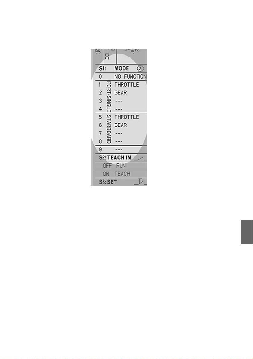
5. Turn the rotary coding switch S1 (10, fig. 12) to define the
actuator’s function. Refer to table 10 for information on the
functions. See also the actuator’s type plate as shown in
fig. 3.
Table 10: Rotary coding switch S1, settings
No. Function
0No Function, delivery state
1 SINGLE: throttle
TWIN: throttle portside
2 SINGLE: gear
TWIN: gear portside
3Alternative
4Alternative
5 SINGLE: no function
TWIN: throttle starboard
6 SINGLE: no function
TWIN: gear starboard
7Alternative
8Alternative
9Alternative
Page 34
AVENTICS | ECS Actuator | R417002911–BDL–001–AA 33
Commissioning
Fig. 13: Settings of switch S1 (printed on type plate)
6. Proceed accordingly to set the function of all other
actuators.
7. After finishing the setting a different function must be
assigned to every actuator. (The rotary coding switches S1
must be set to different figures.)
8.3 Starting the auto-configuration
Auto-config Marex ECS features automatic configuration (auto-config). Only
few steps are required to log on and configure components.
Always perform those steps,
W if you have installed a new Marex ECS,
W if you have replaced a control head,
W if you have enhanced the system and added another control
English
Page 35

34 AVENTICS | ECS Actuator | R417002911–BDL–001–AA
Commissioning
head,
W if you have removed and reinstalled a control head.
Fig. 14: Marex ECS Wiring Harness with auto-config connector
Page 36

AVENTICS | ECS Actuator | R417002911–BDL–001–AA 35
Commissioning
Proceed as follows to start the auto-config:
1. Power Marex ECS completely off.
2. Install the Control Head Type 500-ECS and establish the
electrical connections as described in chapter 7, Assembly.
3. Disconnect the auto-config plug from the Marex ECS Wiring
Harness as shown in fig. 15.
Fig. 15: Disconnect the auto-config plug
4. Switch the power supply on.
The auto-config is running. The process may take a few
minutes.The control head is being registered and
configured with standard settings. The device status LEDs
flash alternately red and green on all Marex ECS
components.
When the LEDs flash green on all components, the auto-
config is finished.
English
Page 37

36 AVENTICS | ECS Actuator | R417002911–BDL–001–AA
Commissioning
5. Reattach the Autoconfig-connector to the corresponding
jack on the wiring harness (fig. 16). Make sure the connector
fits securely.
Fig. 16: Reattach the autoconfig-connector
The configuration is complete.The device status LEDs are
indicating the components‘ status again.
If you wish to modify settings you can now make the necessary
changes using the wireless MarexLink network. Refer to the
MarexECS QuickGuide for further information (see chapter 1.2,
Required and additional documentations).
6. Test all system functions first at standstill. Verify if the
levers of all actuators connected move corresponding to the
functions which have been set.
The commissioning is completed if all functions are working
without failure.
Repeat the auto-configuration if the process is interrupted or
red LEDs flash or light up permanently.
Page 38

AVENTICS | ECS Actuator | R417002911–BDL–001–AA 37
Commissioning
8.4 Connecting the push/pull cable
After all electric connections have been established and the
actuators are operational, set up the mechanical connection
between the MarexECS Actuator and the lever for speed or gear
setting at the boat’s engine using a push/pull cable.
Only use push/pull cables type 33C as the fixing points on
the MarexECS Actuator are designed for that type of cable.
Please note the push/pull cables are not included in the
delivery, see also chapter 14, Accessories.
Proceed as follows:
1. Select the lever at the throttle or gearbox which shall be
connected first.
2. Check if it is already prepared for the connection of a push/
pull cable. If not, a mounting kit is available including ball
joint and mounting material (3236990062).
Connect the push/pull cable following the instructions of the
manufacturer:
3. Mount the ball of the joint onto the lever in such a way that
the linear lever travel does not exceed 76mm. We
recommend a lever travel of 70mm approximately (fig. 17).
Fig. 17: Adjusting lever and counter bearing
English
Page 39

38 AVENTICS | ECS Actuator | R417002911–BDL–001–AA
Commissioning
4. Do then mount the counter bearing of the push/pull cable
(clamp) in a distance of 188mm to the ball. The lever must
be in the center position. Make sure that the swiveling part
of the push/pull cable is equally far deflected to both sides
through the arch-shaped movement of the ball (fig. 17).
5. Now, mount the ball joint on the push/pull cable, fix the
jacket of the push/pull cable on the counter bearing using
the clamp and insert the ball joint into the ball on the
adjusting lever.
6. Make sure that the adjusting lever with the push/pull cable
can move over the complete range without any obstructions.
Now mount the other end of the push/pull cable on the
corresponding MarexECS Actuator. Make sure to use the
shortest possible way and avoid bends when routing the cable.
Be aware that the efficiency of the push/pull cable is reduced
with every bend. Cables which fulfill the following requirements
will work best:
W Smallest bending radius 200mm
W Traction 700N at maximum
W Force 300N at maximum
W Bending angle 90°
– Usable force = 82% of force applied
W Bending angle 360°:
– Usable force = 55% of force applied
Page 40

AVENTICS | ECS Actuator | R417002911–BDL–001–AA 39
16
17
18
Commissioning
7. At first, screw the ball head which is included in the delivery
onto the lever of the MarexECS Actuator. Use the inner
threaded hole (fig. 18, 16), if due to the mounting situation on
the adjusting lever of the throttle or gearbox a stroke
smaller than 51mm is required. For a longer stroke, use the
other threaded hole (fig. 18, 17).
Fig. 18: Marex ECS Actuator with lever and mounting bores for the ball
joint
16 Position 2 inch (51mm)
17 Position 3 inch (76mm)
18 Markings for stroke limitation
8. Screw the ball joint onto the push-pull cable, fix the jacket of
the push/pull cable to the counter bearing of the MarexECS
Actuator by means of the clamp and insert the ball joint onto
the ball on the lever (fig. 19).
English
Page 41

40 AVENTICS | ECS Actuator | R417002911–BDL–001–AA
4
3
2
Commissioning
Fig. 19: Push/Pull cable with mounting and MarexECS Actuator
2 Ball joint (socket and ball)
3 Push/Pull cable
4 Clamp with screws
9. Move the lever of the Marex ECS actuator by hand in both
directions so that the lever on the throttle or gearbox
executes the full stroke. When doing so, the marking on the
lever of the MarexECS Actuator must always remain
between the markings for the stroke limitation, see fig. 18.
The marking in the middle serves for orientation only, the
center position can set separately later at your choice.
10. If the stroke of the MarexECS Actuator is not sufficient to
adjust the lever on gearbox or throttle, reduce the stroke
required by relocating the fixation point on the adjusting
lever of throttle or gearbox in the direction of the pivoting
point.
You have established all connections which are necessary for
the operation of the MarexECS Actuator.
O Proceed accordingly with the other actuators.
O Before switching on the power supply and setting the end
positions (chapters 8.5 and 8.6), detach the ball joints from
the ball bearing (fig. 19) in order to avoid unintended hitting
against the end positions.
Page 42

AVENTICS | ECS Actuator | R417002911–BDL–001–AA 41
Commissioning
8.5 Setting up the actuator for the gear control
Proceed as follows to store the positions which the actuator’s
lever shall approach (teach-in). It is essential that you store the
positions in the order given in the following instructions.
1. Detach the ball joint from the ball bearing on the actuator
(fig. 19) in order to avoid unintended hitting against the end
positions.
2. Switch the power supply on.
3. Set the slide switch S2 (14) to "ON". The red and green LEDs
flash:
OFF ---> ON
4. Reattach the ball joint on the ball bearing on the actuator (fig
19) and move the lever of the actuator manually so that the
adjusting lever of the gearbox is in the FORWARD position.
5. Push switch S3 to confirm the setting. The red and greed
LEDs stay on for a short time. The position is stored.
6. Move the lever of the actuator manually so that the adjusting
lever of the gearbox is in the NEUTRAL position.
7. Push switch S3 to confirm the setting. The red and green
LEDs stay on for a short time. The position is stored.
8. Move the lever of the actuator manually so that the adjusting
lever of the gearbox is in the REVERSE position.
English
Page 43

42 AVENTICS | ECS Actuator | R417002911–BDL–001–AA
Commissioning
9. Push switch S3 to confirm the setting. The red and green
LEDs stay on for a short time. The position is stored.
10. Set switch S2 to "OFF". The teach-in process is complete.
The actuator is ready for use now. The red LED is off. The
green LED is permanently illuminated.
OFF <--- ON
11. With twin engines, proceed accordingly with the second
actuator for the gearbox.
8.6 Setting up the actuator for the throttle
control
Proceed as follows to store the positions which the actuator’s
lever shall approach (teach-in). It is essential that you store the
positions in the order given in the following instructions.
1. Detach the ball joint from the ball bearing on the actuator
(fig. 19) in order to avoid unintended hitting against the end
positions.
2. Switch the power supply on.
3. Set the slide switch S2 (14) to "ON". The red and green LEDs
flash:
OFF ---> ON
4. Reattach the ball joint on the ball bearing on the actuator (fig
19) and move the lever of the actuator manually so that the
adjustment lever of the throttle is in the MINRPM position.
Page 44

AVENTICS | ECS Actuator | R417002911–BDL–001–AA 43
Commissioning
5. Push switch S3 to confirm the setting. The red and greed
LEDs stay on for a short time. The position is stored.
6. Move the lever of the actuator manually so that the
adjustment lever of the throttle is in the MAXRPM position.
7. Push switch S3 to confirm the setting. The red and green
LEDs stay on for a short time. The position is stored.
8. Set switch S2 to "OFF". The teach-in process is complete.
The actuator is ready for use now. The red LED is off. The
green LED is permanently illuminated.
OFF <--- ON
9. With twin engines, proceed accordingly with the second
actuator for the throttle control.
Assembly, setting and commissioning of the MarexECS
Actuator are now complete.
O Test all system functions first at standstill then at slow
speed.
You will find further information in the MarexECS
QuickGuide, see also chapter 1.2.
English
Page 45

44 AVENTICS | ECS Actuator | R417002911–BDL–001–AA
Maintenance and repair
9 Maintenance and repair
9.1 Cleaning
NOTICE
Product damage due to inappropriate cleaning
Cleaning agents containing solvents may damage the
product's surface and cause premature aging.
O Do only use solvent-free, non-abrasive cleaning agents.
O Never use pressure washers or steam cleaners to clean
the Marex ECS Actuator.
Clean the product only by using a slightly moistened, lint-free
cloth. Only use water or mild cleaning agents.
9.2 Inspection
Make sure the component is always in technically perfect
condition. Check the Marex ECS Actuator regularly for visual
damage. Make sure all connectors fit securely.
9.3 Maintenance
The Marex ECS Actuator does not require maintenance.
Notice Do not attempt to repair a damaged actuator yourself. In case of
defects, always replace the complete actuator.
Page 46

AVENTICS | ECS Actuator | R417002911–BDL–001–AA 45
Disassembly and replacement
10 Disassembly and replacement
CAUTION
Injury hazard and material damage due to unmaneuverable
boat
If you dismantle or replace the Marex ECS Actuator while the
boat is in motion, the ability to steer may be lost.
O Only dismantle the actuator if the boat is not in
operation.
NOTICE
Material damage due to applied supply voltage
Attaching and removing plugs and connectors under power
can destroy the component.
O Only perform assembly or disassembly work on
electrical connections if components and cables are
powered off.
Proceed as follows to dismantle the Marex ECS Actuator:
1. Switch Marex ECS off.
2. Make sure the Marex ECS Actuator is powered off.
3. Remove the electrical connections (6) and (7) and the
grounding cable (8) (fig 7).
4. Remove the push/pull cable (3) (fig. 19).
5. Loosen the mounting nuts. You may now remove the
Marex ECS Actuator.
6. If applicable, install a new Marex ECS Actuator by following
the steps described in chapter 7, Assembly.
English
Page 47

46 AVENTICS | ECS Actuator | R417002911–BDL–001–AA
Disposal
11 Disposal
NOTICE
Environmental damage due to improper disposal
Electronic components require special waste treatment and
must only be disposed of by approved specialist companies.
O Dispose of electronic scrap in an environmentally sound
way. Consult the responsible local authorities regarding
the environmentally sound disposal.
O Dispose of the packaging in an environmentally compatible
way.
Page 48

AVENTICS | ECS Actuator | R417002911–BDL–001–AA 47
12 Error search and
troubleshooting
In case of an alarm signal on the Marex ECS control head, it may
be necessary to check the condition of the actuator(s). Two LEDs
(see fig. 12) are provided under the transparent cover of the
actuator to indicate its functional condition (see 5.4). Compare
the LED signals to the indications in the table below:
Table 11: LED-signals on the actuator
LED-signal Meaning What to do
This actuator is defective. Replace the actuator, proceed as described in
chapters 7 and 8 and repeat the Marex ECS auto-
config (8.1).
This actuator works fine, but
another actuator may be
affected.
The actuator has stopped
working due to overload.
Power supply failure or the
power is beyond the admissible
range or the communication
between the actuator and the
control unit is disturbed.
Check the function of all other actuators, if available.
Refer to the instructions in this table.
Check manually if the actuator’s adjusting lever can
move freely by pulling the push/pull cable.
Eliminate the cause of the stiff movement.
Dis- and reconnect the POWER cable and try again.
Check the PROPULSION cable for proper connection
and visible damage. Replace the cable if defective.
Measure the voltage at battery and system
components. Pay special attention to correct polarity
and fuses.
Make sure the wiring harness is properly connected to
the control unit with the retaining catches clicked into
place.
Error search and troubleshooting
English
12.1 Reestablishing the power supply
If the actuator is not supplied with power though all cables are
connected, this may have different causes:
O Make sure all connectors are firmly attached.
Page 49

48 AVENTICS | ECS Actuator | R417002911–BDL–001–AA
Error search and troubleshooting
O Check the POWER cable for signs of damage or wear and
replace it if necessary.
O Measure the battery voltage to check if the power supplied
is within the admissible range for the actuator.
Table 12: Admissible power range
MarexECS Actuator 12 VDC 9 - 31,2V
MarexECS Actuator 24 VDC 18 - 31,2V
O Check if the polarity is correct.
O Check if appropriate, functioning fuses are installed.
Table 13: Fuses
MarexECS Actuator12 VDC 30 A
MarexECS Actuator 24 V DC 16A
If, after verifying power cables, connectors and battery voltage,
you cannot identify the failure, refer to
www.marex-shipcontrols.com for further information and
support.
Page 50

AVENTICS | ECS Actuator | R417002911–BDL–001–AA 49
13 Technical data
Table 14: Technical data
Dimensions
width x height x depth 146 mm x 306.5 mm x 134 mm
Weight 3kg approximately
Supply voltage 12VDC (-25%/+30 %) (R417002102)or
24VDC (-25%/+30 %) (R417002103)
Typical curre nt consumption 6A (1 2 V)
3A (24V)
Maximum current consumption 12A (12V)
6 A (24V)
Rated stroke 76mm (3 inch)
Rated force 150N
Temporary force max. 180 N
Admissible ambient temperature 248 to 350K (-25°C to +77° C)
Admissible storage temperature 233K to 358K (-40°C to +85°C)
Protection class IP 65 - EN 60529 (IEC 60529)
Vibration resistance IEC 60068-2-6
Range 2-13 Hz: ± 1.6mm
Range 13-100 Hz: ± 4g
Shock resistance 10g / 11ms
Rel. humidity 5% - 98% incl. condensation
Material Aluminum, anodized
Technical data
English
Page 51

50 AVENTICS | ECS Actuator | R417002911–BDL–001–AA
Accessories
14 Accessories
Part Material No.
Cables
POWER cable, 5m R419801567
POWER cable, 10m (not suitable for Marex ECS Actuators 12V DC) R419801316
POWER cable, dual battery connection, 5m R419801568
POWER cable, dual battery connection, 10m
(not suitable for Marex ECS Actuators 12V DC)
POWER cable, ignition input, 20m R419801547
GEAR control cable, forward/reverse, 10 m R419801334
GEAR control cable, forward/reverse, solenoid valve connector, 5m R419801335
GEAR control cable, forward/reverse, solenoid valve connector, 10m R419801336
THROTTLE control cable, 4 -20 mA, 10m R419801320
THROTTLE control cable, 4- 20 mA, 20m R419801321
THROTTLE control cable, 0 - 5V, 10 m R419801322
THROTTLE control cable, 0 - 5V, 20 m R419801323
THROTTLE control cable, PWM, 10m R419801324
THROTTLE control cable, PWM, 20m R419801325
AUX control cable, start interlock contact, safety stop, high idle, 10m R419801344
AUX control cable, start interlock contact, 10m R419801345
ALARM control cable, alarm and monitoring system interface, 10m R419801319
STATION/PROPULSION bus cable, 1m R419801349
STATION/PROPULSION bus cable, 5m R419801350
STATION/PROPULSION bus cable, 10m R419801351
STATION/PROPULSION bus cable, 15m R419801352
STATION/PROPULSION bus cable, 20m R419801353
STATION/PROPULSION bus cable, 30m R419801354
STATION/PROPULSION bus cable connector, 0.15m R419801362
Push/Pull cable, stroke 76mm, 2 m 3236994152
Push/Pull cable, stroke 76mm, 3 m 3236994162
Mounting kit for push/pull cable 3236990062
R419801522
Page 52

AVENTICS | ECS Actuator | R417002911–BDL–001–AA 51
Accessories
Part Material No.
Wiring harness
Marex ECS single wiring harness R419302201
Marex ECS twin wiring harness R419302202
Control head
Control head type 500-ECS, single, chrome-plated R417002881
Control head type 500-ECS, twin, chrome-plated R417002880
Control head type 500-ECS, single, black R417002810
Control head type 500-ECS, twin, black R417002808
Control unit
Marex ECS control unit R419302110
Terminating resistor
Bus terminating resistor 8941054274
Actuator
Marex ECS actuator 12 V DC R417002894
Marex ECS actuator 24 V DC R417002895
English
Page 53

52 AVENTICS | ECS Actuator | R417002911–BDL–001–AA
Appendix
15 Appendix
15.1 Installation drawings
Fig. 20: Installation drawing Marex ECS Actuator R417002102 and R417002103
Page 54

AVENTICS | ECS Actuator | R417002911–BDL–001–AA 53
Alphabetical Index
16 Alphabetical Index
W A
Additional
documentation 4
ALARM control cable 50
Ambient temperature 49
Assembly 20
Installation
conditions 20
Safety instructions 11
Auto-config 30
Automatic
configuration 30
AUX control cables 50
W C
Cables
ALARM control 50
AUX control 50
GEAR control 50
POWER 50
STATION/PROPULSION
bus 50
THROTTLE control,
THROTTLE control
cables 50
Circuit breakers 29
Classification 17
Germanischer Lloyd 17
Cleaning 12, 44
Commissioning 30
Define actuator
function 31
Safety instructions 11
Settings S1 32
Store lever positions 41
Teach-in 41
Connect actuator 24
Connect power supply 27
Connect push/pull
cable 30
Control unit 51
W D
Define function 31
Delivery
Scope 13
Delivery, check 18
Description actuator 14
Designations 6
Dimensions 49
Disassembly 45
Disassembly and
replacement 45
Disposal 12, 46
Documentation
Designations 6
Required and
additional 4
Symbols 6
Validity 4
Drilling template 24
Dual battery operation 27
W F
Force, rated 49
Fuses 29
W G
GEAR control cables 50
General safety
Page 55

54 AVENTICS | ECS Actuator | R417002911–BDL–001–AA
Alphabetical Index
instructions 10
Germanischer Lloyd 17
W H
Humidity 49
W I
Identification 17
Improper use 9
Indicating elements 15
Inspection 44
Installation conditions 20
Installation drawing 52
Installation engine
room 21
Installation site 20
Intended use 8
W L
LEDs, modes of
operation 16
W M
Maintenance 44
Marex ECS Actuator
Connect 24
Mechanical
connection 30
Operating and indicating
elements 15
Performance
description 14
Marex ECS Actuator,
identifcation 17
Marex ECS Actuator,
overview 15
Marex ECS auto-config 30
Material and product da-
mage, notes 12
Mechanical connection 30
Mounting actuator 23
W O
Operating elements 15
Operation, safety
instructions 11
Operator’s obligations 11
Overview mounting the
actuator 23
W P
Performance
description 14
Personnel, qualification 9
POWER cable one
battery 28
POWER cables 50
Power cables dual
battery 28
Power supply 49
Power supply, connect 27
Power, dual battery 27
Product description 14
Product view 15
PROPULSION cables, maximum total length 27
Protection class 49
Push/Pull cable,
characteristics 38
W Q
Qualification of
personnel 9
W R
Repair 44
Page 56

AVENTICS | ECS Actuator | R417002911–BDL–001–AA 55
Alphabetical Index
Replacement 45
Required
documentation 4
W S
S1 settings 32
Safety instructions
Assembly 11
Commissioning 11
General 10
Operation 11
Product- and
technology-related 11
Scope of delivery 13
Set function (S1) 32
Settings rotary switch
S1 32
STATION/PROPULSION
bus cables 50
Storage temperature 49
Stroke, rated 49
Supply voltage 49
W V
Validity of
documentation 4
View product 15
W W
Weight 49
Wiring harness 51
W T
Teach-in 41
Technical data 49
Temperature
Ambient 49
Storage 49
Terminating resistor 51
Transport 18
Troubleshooting 47
Type plate 17
W U
Use
Improper 9
Intended 8
Page 57

Page 58

Page 59

Page 60

AVENTICS
Ulmer Straße 4
30880 Laatzen
Phone +49 511 213-62 51
Fax: +49 511 213-61 65
www.marex-shipcontrols.com
marinesales@aventics.com
Further addresses:
www.aventics.com
The data specified above only serve to
describe the product. No statements
concerning a certain condition or
suitability for a certain application can be
derived from our information. The given
information does not release the user from
the obligation of own judgement and
verification. It must be remembered that
our products are subject to a natural
process of wear and aging.
An example configuration is depicted on
the title page. The delivered product may
thus vary from that in the illustration.
Translation of the original operating
instructions. The original operating
instructions were created in the German
language.
R417002911–BDL–001–AA
Subject to modifications. © All rights
reserved by AVENTICS GmbH, even and
especially in cases of proprietary rights
applications. It may not be reproduced or
given to third parties without its consent.
 Loading...