

Инструкция по эксплуатации: Электромеханический переключатель, срабатывающий от давления, с сертификацией ATEX, PM1 | AVENTICS
Table of contents
 Loading...
AVENTICS Инструкция по эксплуатации: Электромеханический переключатель, срабатывающий от давления, с сертификацией ATEX, PM1 | AVENTICS Manuals & Guides

Betriebsanleitung | Operating instructions | Notice d’instruction
Istruzioni per l'uso | Instrucciones de servicio | Bruksanvisning | Инструкция по
эксплуатации
R412018626-BAL-001-AI
2021-11; Replaces: 2016-04
DE/EN/FR/IT/ES/SV/RU
AVENTICS™ PM1
Elektromechanischer Druckschalter, ATEX-zertifiziert
Electromechanical pressure switch, ATEX certified
Manostat électromécanique, certifié ATEX
Pressostato elettromeccanico, certificatoATEX
Presostato electromecánico, con certificación ATEX
Elektromekanisk tryckvakt, ATEX-certifierad
Электромеханический переключатель, срабатывающий от давления, с
сертификацией ATEX
II 3G Ex nC IIC T4 Gc
II 3D Ex tc IIIC T135°C Dc
-20 ≤ T amb ≤ 80°C
Cert-No. EPS 21 ATEX 1 188 X

1 Zu dieser Dokumentation
Diese Anleitung enthält wichtige Informationen, um das Produkt sicher und sachgerecht zu montieren und in Betrieb zu nehmen.
u Lesen Sie diese Anleitung vollständig und insbesondere das Kapitel „Sicher-
heitshinweise“, bevor Sie mit dem Produkt arbeiten.
1.1 Zusätzliche Dokumentationen
1. Beachten Sie auch die Anleitungen der übrigen Anlagenkomponenten.
2. Beachten Sie außerdem allgemein gültige, gesetzliche und sonstige verbindli-
che Regelungen.
1.2 Darstellung von Informationen
3. Halten Sie die in den technischen Daten genannten Betriebsbedingungen und
Leistungsgrenzen ein.
2.2 Qualifikation des Personals
Alle mit dem Produkt verbundenen Tätigkeiten erfordern grundlegende mechanische, pneumatische und elektrische Kenntnisse sowie Kenntnisse der zugehörigen Fachbegriffe. Um die Betriebssicherheit zu gewährleisten, dürfen diese
Tätigkeiten daher nur von einer entsprechenden Fachkraft oder einer unterwiesenen Person unter Leitung einer Fachkraft durchgeführt werden. Eine Fachkraft ist,
wer aufgrund seiner fachlichen Ausbildung, seiner Kenntnisse und Erfahrungen
sowie seiner Kenntnisse der einschlägigen Bestimmungen die ihm übertragenen
Arbeiten beurteilen, mögliche Gefahren erkennen und geeignete Sicherheitsmaßnahmen treffen kann. Eine Fachkraft muss die einschlägigen fachspezifischen Regeln einhalten.
1.2.1 Warnhinweise
In dieser Dokumentation stehen Warnhinweise vor einer Handlungsabfolge, bei
der die Gefahr von Personen- oder Sachschäden besteht. Die beschriebenen
Maßnahmen zur Gefahrenabwehr müssen eingehalten werden.
Aufbau von Warnhinweisen
SIGNALWORT
Art und Quelle der Gefahr
Folgen bei Nichtbeachtung
u Maßnahmen zur Gefahrenabwehr
Bedeutung der Signalwörter
GEFAHR
Unmittelbar drohende Gefahr für das Leben und die Gesundheit von Personen.
Das Nichtbeachten dieser Hinweise hat schwere gesundheitliche Auswirkun-
gen zur Folge, bis hin zum Tod.
VORSICHT
Möglicherweise gefährliche Situation.
Das Nichtbeachten dieser Hinweise kann leichte Verletzungen zur Folge haben
oder zu Sachbeschädigungen führen.
ACHTUNG
Möglichkeit von Sachbeschädigungen oder Funktionsstörungen.
Das Nichtbeachten dieser Hinweise kann Sachbeschädigungen oder Funktions-
störungen zur Folge haben, jedoch keine Personenschäden.
1.2.2 Symbole
Empfehlung für den optimalen Einsatz unserer Produkte.
Beachten Sie diese Informationen, um einen möglichst reibungslosen
Betriebsablauf zu gewährleisten.
2.3 Allgemeine Sicherheitshinweise
• Beachten Sie die gültigen Vorschriften zur Unfallverhütung und zum Umweltschutz im Verwenderland und am Arbeitsplatz.
• Setzen Sie das Produkt nur dann in sicherheitsrelevante Anwendungen ein,
wenn diese Verwendung ausdrücklich in der Dokumentation des Produkts
spezifiziert und erlaubt ist.
• Verwenden Sie AVENTICS-Produkte nur in technisch einwandfreiem Zustand.
• Prüfen Sie das Produkt auf offensichtliche Mängel, wie beispielsweise Risse im
Gehäuse oder fehlende Schrauben, Abdeckkappen, Dichtungen.
• Sie dürfen das Produkt grundsätzlich nicht verändern oder umbauen.
• Die Gewährleistung erlischt bei fehlerhafter Montage.
• Warnungen und Angaben zum Produkt dürfen nicht mit Farbe etc. überdeckt
werden, sondern müssen stets gut lesbar sein.
• Verwenden Sie ausschließlich die am Gerät angeschlossene Anschlussleitung
und stellen Sie eine feste Verlegung der Anschlussleitung sicher.
• Lösen Sie niemals die Kabelverschraubung vom Gerät oder der Anschlussleitung.
• Stellen Sie sicher, dass die Anschlussleitung gegen UV-Einflüsse geschützt ist.
2.4 Produkt- und technologieabhängige Sicherheitshinweise
• Verlegen Sie die Kabel und Leitungen so, dass diese nicht beschädigt werden
und niemand darüber stolpern kann.
• Das Produkt darf nicht bei kritischen Umgebungsbedingungen (z. B. starke
Temperaturschwankungen) und nicht in aggressiver Umgebungsluft (z.B. Lösungsmitteldämpfe, salzhaltige Luft) montiert und betrieben werden.
• Beim Einsatz des Produkts sind die Umgebungsbedingen gemäß der IP-Schutz
Anforderungen (IP65) einzuhalten.
2.5 ATEX-Hinweise zum Explosionsschutz
Die Druckschalter der Serie PM1-ATEX sind gemäß der beigefügten Konformitätserklärung zertifiziert und gekennzeichnet. Sie sind wie folgt einsetzbar (siehe
gKonformitätserklärung):
• In rein gasexplosionsgefährdeten Bereichen der Zone 2 (Kategorie 3G)
• In Bereichen mit brennbaren Stäuben der Zone 22 (Kategorie 3D)
2 Sicherheitshinweise
Das Produkt wurde gemäß den allgemein anerkannten Regeln der Technik hergestellt. Trotzdem besteht die Gefahr von Personen- und Sachschäden, wenn Sie
die folgenden grundsätzlichen Sicherheitshinweise und die Warnhinweise vor
Handlungsanweisungen in dieser Anleitung nicht beachten.
1. Bewahren Sie die Anleitung so auf, dass sie jederzeit für alle Benutzer zugäng-
lich ist.
2. Geben Sie das Produkt an Dritte stets zusammen mit der Betriebsanleitung
weiter.
2.1 Bestimmungsgemäße Verwendung
Das Produkt darf erst in Betrieb genommen werden, wenn es in die Maschine/die
Anlage, für die es bestimmt ist, eingebaut ist.
1. Verwenden Sie den Druckschalter nur, um mittels Druckluft elektrische Kon-
takte zu öffnen und zu schließen.
2. Verwenden Sie als Medium ausschließlich Druckluft.
AVENTICS™ PM1 | R412018626-BAL-001-AI | Deutsch 2

GEFAHR
5
30
48,5
68
ca.74
5
3m / 7m
2
5
20
10
30
Ø5,2
1,15
Ø8
1
2
3
G1/4"
5
30
48,5
Ø9,6
12
+2,0
-0,5
73
ca.79
3m / 7m
2
5
20
30
15
Ø5,2
1
2
Gefahr der Entstehung einer Zündquelle durch unzulässige Betriebsbedingungen, Anschlüsse und Parameter!
Betreiben des PM1 unter unzulässigen Betriebsbedingungen kann zur Überhitzung der Oberflächen des PM1 und/oder zur Bildung einer Zündquelle führen.
1. Beachten Sie die zulässigen Betriebsbedingungen, insbesondere Umge-
bungs- und Mediumstemperatur.
2. Beachten Sie den eingeschränkten Temperaturbereich unter ATEX-Bedin-
gungen. Sorgen Sie dafür, dass die Temperatur des Mediums und der Umgebung den in den technischen Daten angegebenen Wert (80°C) nicht
überschreitet.
3. Werden Temperaturen von >+70°C erreicht, ist darauf zu achten, dass das
Kabel fest verlegt wird.
4. Stellen Sie sicher, dass die zulässige Temperatur nicht durch Druckschwan-
kungen überschritten wird.
5. Bei Installation, Wartung oder Reparatur sind die Ex-Vorschriften, insbeson-
dere EN60079-17 sowie die einschlägigen nationalen Vorschriften (z. B.
89/391/EWG, Artikel7, Absatz5 und 8, IEC60364ff.) zu beachten und von
einer Elektrofachkraft auszuführen.
6. Bei der Verwendung des Betriebsmittels in Bereichen der Zone 22 (Staub
3D) muss der Schutz die Anforderungen von EN60079-31 (IP-Schutzgrad)
erfüllen oder es sind Staubablagerungen auf andere Weise zu vermeiden.
Bei Nichtbeachtung dieser Hinweise verliert das Gerät seine Ex-Zulassung!
4.3 Übersicht Druckschalter PM1, ATEX-zertifiziert
4.3.1 Pneumatischer Anschluss Flansch
3 Lieferumfang
Im Lieferumfang sind enthalten:
• 1x Elektromechanischer Druckschalter PM1 mit Kabel 3 m oder 7 m
• 2x Befestigungsschraube, bei Flanschausführung
• O-Ring, bei Flanschausführung
• Betriebsanleitung
4 Zu diesem Produkt
4.1 Produktbeschreibung
Der PM1 wird verwendet, um bei Erreichen eines zuvor eingestellten Druckbereichs einen elektrischen Kontakt zu öffnen bzw. zu schließen.
4.2 Leistungsbeschreibung
Der PM1 wird am Anschluss G1/4 bzw. am Flansch mit einem entsprechenden
Medium beaufschlagt. Bei Erreichen des eingestellten Schaltdrucks betätigt ein
Balg über eine Mechanik einen Mikroschalter (Umschalter).
Der Kontakt wechselt (siehe gAbb.5 und gAbb.6)
• bei steigendem Druck von 1-2 nach 1-3,
bei sinkendem Druck von 1-3 nach 1-2.
• bei steigendem Unterdruck von 1-3 nach 1-2,
bei sinkendem Unterdruck von 1-2 nach 1-3
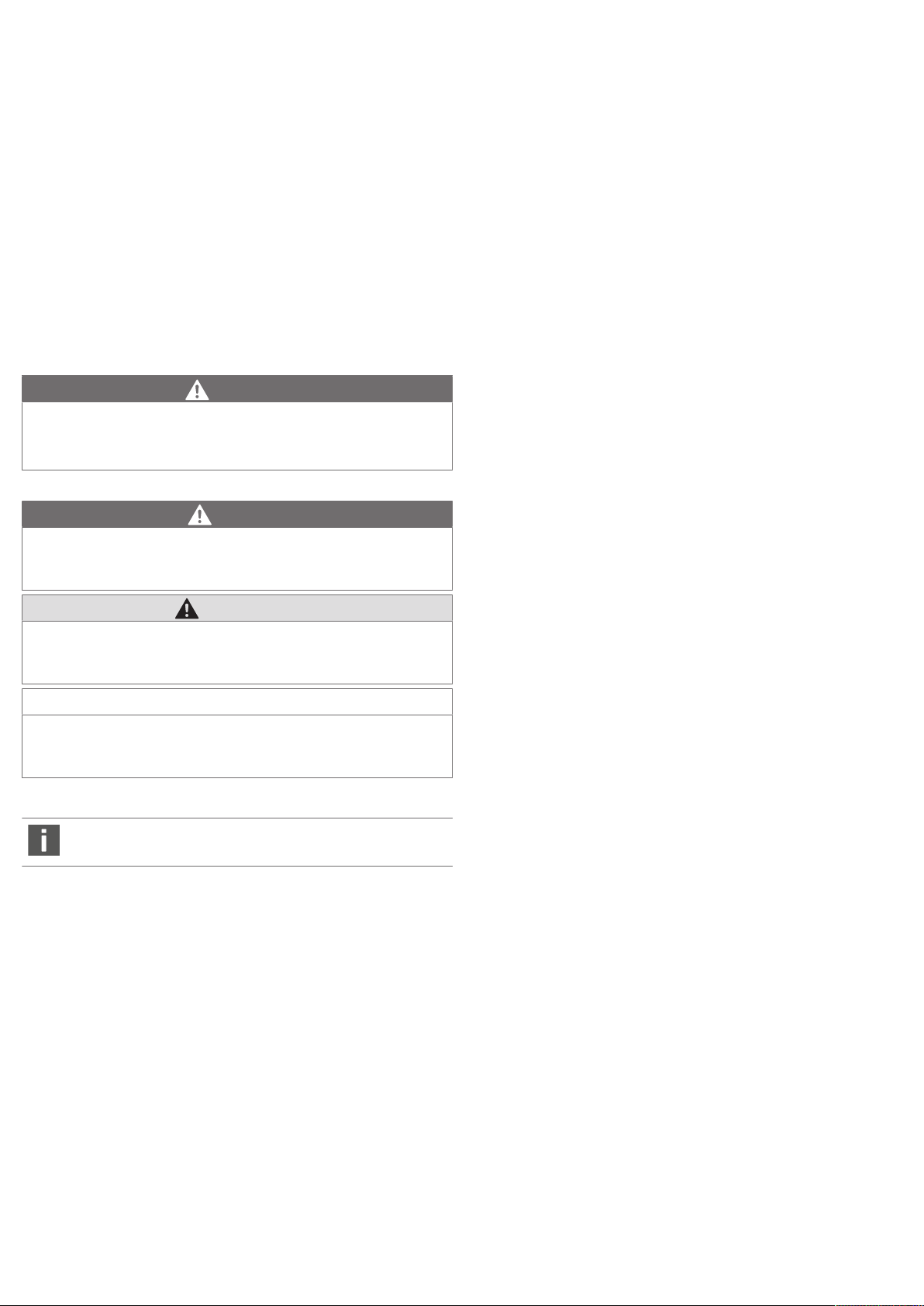
Abb.1: Pneumatischer Anschluss Flansch
1 O-Ring Ø 5x1,5 (im Lieferumfang ent-
halten)
3 Zylinderschraube M5x30 ISO 1207
(2x); MA = 2,5+0,5 Nm (im Lieferumfang enthalten),
2 Einstellschraube zur Feineinstellung,
selbsthaltend
4.3.2 Pneumatischer Anschluss Innengewinde G1/4
AVENTICS™ PM1 | R412018626-BAL-001-AI | Deutsch 3
Abb.2: Pneumatischer Anschluss Innengewinde G1/4
1 Anschluss G1/4, MA = 12+0,1 Nm 2 Einstellschraube zur Feineinstellung,
selbsthaltend
Die Materialnummern entnehmen Sie bitte dem Online-Katalog.

4.4 Identifikation des Produkts
1
3
2
7290
Made in Germany
20W19
ZZZZ
Set 1,5 b ....
R412XXXXXX - PM1
pe 0,2 - 16bar
U
max
30 V DC / 250 V AC
I
max
3 A
S
max
90 W / 750 VA
AVENTICS GmbH, Ulmer Straße 4, 30880 Laatzen, Germany
1
2
3
4
5
6
7
8
9
10
11
12
13
14
15
16
II 3G Ex nc IIC T4 GC
II 3D Ex tc IIIC T135 °C Dc
-20 °C ≤ T amb ≤ 80 °C
Cert-No. EPS 21 ATEX 1 188 X
BETRIEBSANLEITUNG BEACHTEN
OBSERVE OPERATING INSTRUCTIONS
1
3
2
1
3
2
5
2
1
u Beachten Sie die Produktangaben auf dem Produkt und der Verpackung.
Die ATEX Angaben sind auf der Rückseite des Produkts zu finden.
4.5 Kennzeichnung auf dem Typenschild
Abb.3: Typenschild
1 Interne Werksbezeichnung 2 Herstellerland
3 EAC-Kennzeichen 4 Fachkraftkennzeichnung
5 CE-Kennzeichnen 6 Materialnummer
7 Betriebsdruckbereich 8 max. zulässige Spannung
9 max. Stromaufnahme 10 max. Leistungsaufnahme
11 Seriennummer 12 Herstelleradresse
13 Datumscode* 14 kundenspezifischer Schaltdruck
15 Schaltbild 16 Herstellerlogo
*)
Im 7-stelligen Datumscode geben die ersten vier Stellen das Jahr und die letzten
beiden die Woche an.
Abb.4: Rückseite Typenschild
5 Montage
u Lassen Sie das Produkt vor der Inbetriebnahme einige Stunden akklimatisie-
ren, da sich ansonsten im Gehäuse Kondenswasser niederschlagen kann.
6 Inbetriebnahme und Betrieb
GEFAHR
Explosionsgefahr!
Bei unsachgemäßer Inbetriebnahme in explosionsgefährdeten Bereichen besteht Explosionsgefahr.
u Beachten Sie die Warnhinweise unter g2.5.ATEX-Hinweise zum Explosi-
onsschutz!
VORSICHT
Verletzungsgefahr durch unkontrollierte Bewegungen der Aktoren beim
Einschalten der Pneumatik!
Es besteht Verletzungsgefahr, wenn sich das System in einem undefinierten
Zustand befindet.
u Bringen Sie das System in einen definierten Zustand, bevor Sie es einschal-
ten!
VORSICHT
Anlage steht im Betrieb unter Druck!
Bei unsachgemäßer Installation kann es zur Beschädigung des Druckschalters
oder der Anlage und zu schweren Verletzungen kommen.
u Prüfen Sie vor Inbetriebnahme alle Verbindungen, Anschlüsse und Kompo-
nenten auf korrekte Installation.
6.1 Druckschalter in Betrieb nehmen
Zur Inbetriebnahme des Druckschalters gehen Sie wie folgt vor:
1. Prüfen Sie, ob der Druckschalter richtig montiert ist (sieheg5.Montage und
g2.Sicherheitshinweise, speziell g2.5.ATEX-Hinweise zum Explosions-
schutz) und stellen Sie sicher, dass alle Anschlüsse des Druckschalters korrekt
verbunden sind.
2. Sichern Sie die zu schaltenden Komponenten vor unbeabsichtigten Reaktio-
nen und legen Sie Spannung an.
3. Beaufschlagen Sie die Anlage mit Druckluft.
4. Überprüfen Sie die Schaltausgänge auf ordnungsgemäße Funktion.
6.2 Schaltpunkt einstellen
VORSICHT
Verletzungsgefahr durch Montage unter Druck oder Spannung!
Die Montage unter Druck oder anliegender elektrischer Spannung kann zu Verletzungen führen und das Produkt oder Anlagenteile beschädigen.
1. Schalten Sie den relevanten Anlagenteil drucklos und spannungsfrei, bevor
Sie das Produkt montieren.
2. Sichern Sie die Anlage gegen Wiedereinschalten.
5.1 Druckschalter montieren und pneumatisch anschließen
1. Schalten Sie die Anlage drucklos und spannungsfrei.
2. Verbinden Sie den Druckschalter mit dem Drucksystem:
• Flanschanschluss M5: MA=2,5
+0,5
Nm (siehe gAbb.1)
• Anschluss G1/4: MA=12+1Nm (siehe gAbb.2)
5.2 Druckschalter elektrisch anschließen
Die Adernkennzeichnung entspricht der Kontaktbelegung folgender Abbildung.
Abb.5: Schaltfunktionen 0.2 -16 bar
Die elektrische Installation muss unter Beachtung der einschlägigen nationalen
Vorschriften von einer Elektrofachkraft mit der Qualifikation einer befähigten
Person (nach TRBS 1203 oder gleichwertig) durchgeführt bzw. beaufsichtigt werden.
AVENTICS™ PM1 | R412018626-BAL-001-AI | Deutsch 4
Abb.6: Schaltfunktionen -0.9 -1 bar
Abb.7: Schaltpunkt einstellen
1 Einstellschraube
• Werkseinstellung: Druckschalter=3bar; Vakuumschalter=–0,4bar
• Die Einstellschraube ist selbsthaltend.
Der Schaltpunkt ist stufenlos einstellbar, auch während des Betriebes.
u Verwenden Sie zur Kontrolle des Schaltpunkts ein externes Manometer.
Um den Schaltpunkt auf einen höheren Druck einzustellen:
u Drehen Sie die Einstellschraube (1) nach rechts (+).
Um den Schaltpunkt auf einen geringeren Druck einzustellen:
u Drehen Sie die Einstellschraube (1) nach links (–).

7 Instandhaltung und Instandsetzung
[bar]
p1 (-)
[bar]
p1 (+)
[bar]
p1 (-)
[bar]
p1 (+)
+0,1
+0,3
+0,3
+0,4
+0,5
+0,6
+0,7
+0,8
-0,8
-0,7
-1,0
-1,0 -0,8 -0,6 -0,4 -0,2 +0,4 +0,6 +0,8 +1,0+0,2
-0,9
-0,6
-0,5
-0,4
-0,3
-0,2
-0,1
+0,9
+1,0
+1,1
+1,2
1)
2)
7.1 Reinigung und Pflege
GEFAHR
Explosionsgefahr durch elektrostatische Aufladung!
Beim Reinigen mit einem trockenen Tuch kann die Oberfläche des Druckschalters elektrostatisch aufgeladen werden. Beim Betrieb in explosionsgefährdeten Bereichen besteht dann Explosionsgefahr.
u Reinigen Sie den Druckschalter nur mit einem mit Wasser befeuchteten
Tuch! Verwenden Sie niemals Lösemittel oder aggressive Reinigungsmittel.
u Verwenden Sie zur Reinigung keine Hochdruckreiniger.
7.2 Wartung
Der Druckschalter ist wartungsfrei.
u Wenden Sie sich bei technischen Problemen an die Serviceabteilung von
AVENTICS.
8 Demontage und Austausch
VORSICHT
Explosionsgefahr!
Bei Demontage und Austausch unter Druck und elektrischer Spannung kann es
in explosionsgefährdeten Bereichen zur Explosion kommen.
1. Schalten Sie den relevanten Anlagenteil drucklos und spannungsfrei, bevor
Sie das Produkt montieren.
2. Sichern Sie die Anlage gegen Wiedereinschalten.
1. Schalten Sie die Anlage drucklos und spannungsfrei.
2. Trennen sie die elektrische Verbindung.
3. Lösen Sie die Befestigungsschrauben des Druckschalters.
4. Entfernen Sie den Druckschalter vom Drucksystem.
9 Entsorgung
u Entsorgen Sie das Produkt nach den Bestimmungen Ihres Landes.
Spezifikationen
Der Drucktaupunkt muss mindestens 15 °C unter der Umgebungs- und Mediumstemperatur liegen und darf max. 3 °C betragen.
Der Ölgehalt der Druckluft muss über die gesamte Lebensdauer konstant bleiben.
u Verwenden Sie ausschließlich von AVENTICS zugelassene Öle.
Schaltdruckbereich • –0,9bar bis 1bar (siehe gAbb.8)
• 0,2bar bis 16bar (Schaltdruckbereich min. 0,2bar fallend,
0,5bar steigend) (siehe gAbb.9)
Schaltfrequenz max. 1,6Hz
Elektronik
Betriebsspannung
min./max.
12V–125VDC
12V–250VAC
Weitere technische Daten entnehmen Sie dem Online-Katalog.
Berücksichtigte Normen und Richtlinien
EN IEC 60079-0:2018 Explosionsgefährdete Bereiche–Teil 0:
EN IEC 60079-15:2019 Explosionsfähige Atmosphäre–Teil 15:
EN 60079-31:2014 Explosionsgefährdete Bereiche–Teil 31:
Betriebsmittel - Allgemeine Anforderungen
Geräteschutz durch Zündschutzart „n“
Geräte - Staubexplosionsschutz durch Gehäuse „t“
11.1 Schaltvermögen
Schaltspannung [VAC]
30 48 60 125 250
Typ Stromart Belastungsart max. Schaltstrom [A]
PM1 AC Ohmsche Last 3 3 3 3 3
Induktive Last
DC Ohmsche Last 3 1,2 0,8 0,4
Induktive Last
2)
Bezugsschaltzahl 30/min. Bezugstemperatur +30°C, U=30V
3)
Induktive Last: AC=cos∼0,7°; DC=L/R∼10ms
3)
3 3 3 3 3
2)
2 0,55 0,4 0,05
fn:2
12 Schaltdifferenzdruck-Kennlinie
10 Fehlersuche und Fehlerbehebung
10.1 Verhalten bei Störungen
u Tauschen Sie bei Störungen mit unbekannter Ursache den Druckschalter ge-
gen einen Original-Druckschalter aus.
Einzelne Bauteile des Druckschalters können nicht ersetzt oder repariert werden.
Falls Sie den aufgetretenen Fehler nicht beheben konnten, wenden Sie sich bitte
an eine der Kontaktadressen, siehe Rückseite der Anleitung.
11 Technische Daten
Allgemein
Umgebungs- und
Mediumstemperatur
Schutzart nach EN
60529/IEC529
Pneumatik
Medium Druckluft nach ISO8573-1: 2010,
AVENTICS™ PM1 | R412018626-BAL-001-AI | Deutsch 5
Spezifikationen
-20°C–+80°C
IP65
• max. Partikelgröße: 40µm
• Drucktaupunkt ≤3°C
• Ölgehalt: max. 40mg/m3
Abb.8: Schaltdifferenzdruck-Kennlinie (-0,9 - 1 bar)
1 Steigend
2 Fallend
p1 (+) Oberer Schaltdruck bei steigendem Druck
p1 (-) Unterer Schaltdruck bei sinkendem Druck

16
p1(+) bar
∆ p
1
p1(-) bar
B)A)
15
14
13
12
11
10
9
8
7
6
5
4
3
2
1
0
0 2 4 6 8 10 12 14 16
Abb.9: Schaltdifferenzdruck-Kennlinie (0,2 – 16 bar)
A) p1 (-) Min.
B) p1 (-) Max.
p1 (+) Oberer Schaltdruck bei steigendem Druck
p1 (-) Unterer Schaltdruck bei sinkendem Druck
Δ p1 Max. Schaltdruckdifferenz bzw. Hysterese
Beispiel:
p1 (+) = 8 bar > p1(-) = 7,6 bar
Δ p1 = 0,4 bar
AVENTICS™ PM1 | R412018626-BAL-001-AI | Deutsch 6

AVENTICS™ PM1 | R412018626-BAL-001-AI | Deutsch 7

1 About this documentation
These instructions contain important information for the safe and appropriate assembly and commissioning of the product.
u Read these instructions carefully, especially the section “Notes on Safety”, be-
fore working with the product.
1.1 Additional documentation
1. Also follow the instructions for the other system components.
2. Furthermore, observe all general, statutory and other binding regulations.
2.2 Personnel qualifications
All tasks associated with the product require basic mechanical, pneumatic and
electrical knowledge, as well as knowledge of the respective technical terms. In
order to ensure operational safety, these tasks may only be carried out by qualified personnel or an instructed person under the direction of qualified personnel.
Qualified personnel are those who can recognize possible dangers and institute
the appropriate safety measures, due to their professional training, knowledge,
and experience, as well as their understanding of the relevant regulations pertaining to the work to be done. Qualified personnel must observe the rules relevant to the subject area.
1.2 Presentation of information
1.2.1 Warnings
In this documentation, there are warning notes before the steps whenever there
is a risk of personal injury or damage to equipment. The measures described to
avoid these hazards must be followed.
Structure of warnings
SIGNAL WORD
Hazard type and source
Consequences of non-observance
u Precautions
Meaning of the signal words
DANGER
Immediate danger to the life and health of persons.
Failure to observe these notices will result in serious health consequences, in-
cluding death.
CAUTION
Possible dangerous situation.
Failure to observe these notices may result in minor injuries or damage to
property.
2.3 General safety instructions
• Observe the valid local regulations to protect the environment in the country
of use and to avoid workplace accidents.
• Only use the product in safety-relevant applications if such use is expressly
specified and permitted in the product documentation.
• Only use AVENTICS products that are in perfect working order.
• Examine the product for obvious defects, such as cracks in the housing or
missing screws, caps, or seals.
• Do not modify or convert the product.
• The warranty will not apply if the product is incorrectly assembled.
• Product warnings and information must be legible, i.e. not covered by paint,
etc.
• Only use the connection cable connected to the device and make sure that
the connection cable is permanently installed.
• Never release the cable fitting on the device or connection cable.
• Make sure that the connection cable is protected against UV influences.
2.4 Safety instructions related to the product and technology
• Lay cables and lines so that they cannot be damaged and no one can trip over
them.
• Do not assemble or operate the product in critical ambient conditions (e.g.
high fluctuations in temperature) or in aggressive ambient air (e.g. solvent
gases, salty air).
• When using the product, observe the environmental conditions in accordance
with the IP protection requirements (IP65).
NOTICE
Possibility of damage to property or malfunction.
Failure to observe these notices may result in damage to property or malfunc-
tions, but not in personal injury.
1.2.2 Symbols
Recommendation for the optimum use of our products.
Observe this information to ensure the smoothest possible operation.
2 Notes on safety
The product has been manufactured according to the accepted rules of current
technology. Even so, there is a risk of injury or damage if the following general
safety instructions and the specific warnings given in this instruction manual are
not observed.
1. Keep these instructions in a location where they are accessible to all users at
all times.
2. Always include the operating instructions when you pass the product on to
third parties.
2.1 Intended use
The product may only be commissioned after it has been installed in the machine/system for which it is intended.
1. Only use the pressure switch to open and close electrical contacts using com-
pressed air.
2. Only use compressed air as the medium.
3. Use is permitted only under the operating conditions and within the perfor-
mance limits listed in the technical data.
2.5 ATEX information on explosion protection
PM1-ATEX pressure switches are certified and labeled according to the enclosed
declaration of conformity. They can be used as follows (see gDeclaration of conformity):
• In purely gas explosive areas of zone2 (category3G)
• In areas with flammable dust particles of zone22 (category3D)
DANGER
Danger of an ignition source due to impermissible operating conditions,
connections, and parameters!
Operating the PM1 under impermissible conditions can lead to overheating on
the surfaces of the PM1 and/or formation of an ignition source.
1. Observe the permissible operating conditions, in particular the ambient
and medium temperatures.
2. Note the limited temperature range for ATEX conditions. Make sure that
the values for the medium and ambient temperatures listed in the technical
data (80°C) are complied with.
3. If temperatures of >+70°C are reached, ensure that the cable is fixed.
4. Make sure that permitted temperature levels are not exceeded due to fluc-
tuations in pressure.
5. Observe the relevant Ex guidelines for installation, maintenance, and re-
pair, in particular EN 60079-17 as well as the prevailing national regulations
(e.g. 89/391/EEC, article7, paragraphs5 and8, IEC60364 et seq.). This
work must be performed by an electrical specialist.
6. When using the equipment in areas in zone22 (dust3D), protection stan-
dards must also meet the requirements stated in EN 60079-31 (IP protection class) or other measures must be implemented to prevent deposits of
dust.
The device will lose its Ex approval if these instructions are not complied with!
AVENTICS™ PM1 | R412018626-BAL-001-AI | English 8

3 Scope of delivery
5
30
48,5
68
ca.74
5
3m / 7m
2
5
20
10
30
Ø5,2
1,15
Ø8
1
2
3
G1/4"
5
30
48,5
Ø9,6
12
+2,0
-0,5
73
ca.79
3m / 7m
2
5
20
30
15
Ø5,2
1
2
1
3
2
7290
Made in Germany
20W19
ZZZZ
Set 1,5 b ....
R412XXXXXX - PM1
pe 0,2 - 16bar
U
max
30 V DC / 250 V AC
I
max
3 A
S
max
90 W / 750 VA
AVENTICS GmbH, Ulmer Straße 4, 30880 Laatzen, Germany
1
2
3
4
5
6
7
8
9
10
11
12
13
14
15
16
II 3G Ex nc IIC T4 GC
II 3D Ex tc IIIC T135 °C Dc
-20 °C ≤ T amb ≤ 80 °C
Cert-No. EPS 21 ATEX 1 188 X
BETRIEBSANLEITUNG BEACHTEN
OBSERVE OPERATING INSTRUCTIONS
The scope of delivery includes:
• 1x electromechanical pressure switch PM1 with 3m or 7m cable
• 2x mounting screws, for flange version
• O-ring, for flange version
• Operating instructions
4 About This Product
4.1 Product description
The PM1 is used to open or close an electrical contact when a pre-set pressure
range is reached.
4.2 Performance specifications
An appropriate medium is applied to the PM1 at the G1/4 connection or on the
flange. A bellow actuates a microswitch (change-over switch) via a mechanism
once the preset switching pressure is reached.
The contact switches (see gFig.5 and gFig.6)
• if the pressure increases from 1-2 to 1-3,
if the pressure decreases from 1-3 to 1-2.
• if the underpressure increases from 1-3 to 1-2,
if the underpressure decreases from 1-2 to 1-3
4.3.2 Pneumatic connection, internal thread G1/4
4.3 Overview of PM1 pressure switch, ATEX certified
4.3.1 Pneumatic flange connection
Fig.2: Pneumatic connection, internal thread G1/4
1 Connection G1/4, MA=12+0.1Nm 2 Adjustment screw for fine adjust-
ment, self-holding
For material numbers, please refer to the online catalog.
4.4 Product identification
u Observe the product information on the product and packaging.
The ATEX information can be found on the back of the product.
4.5 Identification on the name plate
Fig.3: Name plate
1 Internal factory designation 2 Country of manufacture
Fig.1: Pneumatic flange connection
1 O-ring ø 5x1.5 (included in scope of
2 Adjustment screw for fine adjust-
delivery)
3 Cylinder screw M5x30 ISO1207 (2x);
MA=2.5+0.5Nm (included in scope
of delivery)
AVENTICS™ PM1 | R412018626-BAL-001-AI | English 9
ment, self-holding
3 EAC mark 4 Specialist marking
5 CE mark 6 Material number
7 Operating pressure range 8 Max. permissible voltage
9 Max. current consumption 10 Max. power consumption
11 Serial number 12 Manufacturer's address
13 Date code* 14 Customer-specific switching pressure
15 Wiring diagram 16 Manufacturer logo
*)
The first four digits of the 7-digit date code show the year and the last two show
the week.
Fig.4: Back side name plate

5 Assembly
1
3
2
1
3
2
5
2
1
u Let the product acclimatize for several hours before commissioning, other-
wise, water may condense in the housing.
CAUTION
Danger of injury if assembled under pressure or voltage!
Assembling when under pressure or electrical voltage can lead to injuries and
damage to the product or system components.
1. Make sure that the relevant system component is without pressure and
voltage before you assemble the product.
2. Protect the system against being restarted.
6.2 Setting the switching point
5.1 Assembling the pressure switch and connecting the pneumatics
1. Make sure that the system is not under voltage or pressure.
2. Connect the pressure switch with the pressure system:
• Flange connection M5: MA=2.5
• Connection G1/4: MA=12+1Nm (see gFig.2)
+0.5
Nm (see gFig.1)
5.2 Electrically connecting the pressure switch
Wire identification corresponds with the contact assignment of the following figure.
Fig.5: Switching functions 0.2 -16 bar
The installation of electrical devices must be carried out in accordance with applicable national regulations and performed or supervised by an electrical specialist
(in compliance with TRBS1203 or equivalent).
Fig.6: Switching functions -0.9 -1 bar
6 Commissioning and operation
DANGER
Danger of explosion!
There is a danger of ignition in explosive areas if the product is not commissioned properly.
u Observe the warnings under g2.5.ATEX information on explosion protec-
tion!
CAUTION
Risk of injury due to uncontrolled actuator movements when the pneumatics are switched on!
There is a danger of personal injury if the system is in an undefined state.
u Put the system in a defined state before switching it on.
Fig.7: Setting the switching point
1 Adjustment screw
• Factory setting: pressure switch=3bar; vacuum switch=–0.4bar
• The adjustment screw is self-holding.
The switching point is continuously adjustable, even during operation.
u To check the switching point, an external pressure gauge must be used.
To set the switching point to a higher pressure:
u Turn the adjustment screw (1) to the right (+).
To set the switching point to a lower pressure:
u Turn the adjustment screw (1) to the left (–).
7 Service and repairs
7.1 Cleaning and servicing
DANGER
Danger of explosion due to electrostatic charge!
Cleaning with a dry cloth may cause the surface of the pressure switch to become electrostatically charged. This can lead to an explosion in explosive areas.
u Use only a water-moistened cloth to clean the pressure switch! Never use
solvents or aggressive detergents.
u Do not use high-pressure cleaners for cleaning.
7.2 Maintenance
The pressure switch is maintenance-free.
u Contact the AVENTICS service department in case of technical problems.
8 Disassembly and exchange
CAUTION
System is operating under pressure!
Incorrect installation could damage the pressure switch or the system and
cause serious injury.
u Before commissioning, check that all connections, ports and components
have been correctly installed.
6.1 Commissioning the pressure switch
Proceed as follows to commission the pressure switch:
1. Check whether the pressure switch is assembled correctly (see g5.Assembly
and g2.Notes on safety, especially g2.5.ATEX information on explosion
protection) and make sure that all pressure switch connections are properly
connected.
2. Secure the components to be switched to prevent unintentional responses,
and apply voltage.
3. Apply the compressed air to the system.
4. Check that the switch outputs are functioning properly.
Danger of explosion!
Disassembly and exchange when under pressure or voltage can lead to explosions in explosive areas.
1. Make sure that the relevant system component is without pressure and
voltage before you assemble the product.
2. Protect the system against being restarted.
1. Make sure that the system is not under voltage or pressure.
2. Disconnect the electrical connection.
3. Loosen the mounting screws on the pressure switch.
4. Remove the pressure switch from the pressure system.
9 Disposal
u Dispose of the product in accordance with the currently applicable regula-
tions in your country.
CAUTION
AVENTICS™ PM1 | R412018626-BAL-001-AI | English 10

10 Troubleshooting
[bar]
p1 (-)
[bar]
p1 (+)
[bar]
p1 (-)
[bar]
p1 (+)
+0,1
+0,3
+0,3
+0,4
+0,5
+0,6
+0,7
+0,8
-0,8
-0,7
-1,0
-1,0 -0,8 -0,6 -0,4 -0,2 +0,4 +0,6 +0,8 +1,0+0,2
-0,9
-0,6
-0,5
-0,4
-0,3
-0,2
-0,1
+0,9
+1,0
+1,1
+1,2
1)
2)
16
p1(+) bar
∆ p
1
p1(-) bar
B)A)
15
14
13
12
11
10
9
8
7
6
5
4
3
2
1
0
0 2 4 6 8 10 12 14 16
10.1 Response to malfunctions
u If malfunctions occur with unknown causes, exchange the pressure switch
with an original pressure switch.
The individual components of the pressure switch cannot be replaced
or repaired.
If you cannot remedy a malfunction, please contact one of the addresses, see the
back of the instructions.
11 Technical data
General
Specifications
Ambient and medium
temperature
Protection class according to EN 60529/
IEC529
Pneumatics
Medium Compressed air acc. to ISO 8573-1: 2010,
The pressure dew point must be at least 15°C below the ambient and medium temperatures
and must not exceed 3°C.
The oil content of compressed air must remain constant during the service life.
u Use only the approved oils from AVENTICS.
Switching pressure
range
Max. switching frequency
Electronics
Min./max. operating
voltage
-20°C to +80°C
IP65
• Max. particle size: 40µm
• Pressure dew point ≤3°C
• Oil content: max. 40mg/m3
• –0.9bar to 1bar (see gFig.8)
• 0.2bar to 16bar (min. switching pressure range 0.2bar falling/0.5bar rising) (see gFig.9)
1.6 Hz
12V–125VDC
12V–250VAC
12 Differential switching pressure characteristic
curve
Fig.8: Differential switching pressure characteristic curve (-0.9 – 1bar)
1 Rising
2 Falling
p1 (+) Upper switching pressure with increasing pressure
p1 (-) Lower switching pressure with decreasing pressure
Further technical data can be found in our online catalog.
Standards and directives complied with
EN IEC 60079-0:2018 Explosive atmospheres–Part 0:
EN IEC 60079-15:2019 Explosive atmospheres–Part 15:
EN 60079-31:2014 Explosive atmospheres–Part 31:
11.1 Switching capacity
Type Current type Load type Max. switching current [A]
PM1 AC Resistive load 3 3 3 3 3
2)
Reference cycle 30/min. reference temperature: +30°C, U=30V
3)
Inductive load: AC=cos~0.7°; DC=L/R~10ms
AVENTICS™ PM1 | R412018626-BAL-001-AI | English 11
DC Resistive load 3 1.2 0.8 0.4
Inductive load
Inductive load
Equipment - General requirements
Equipment protection via type of ignition
protection “n”
Equipment - Protection against dust explosion with housing “t”
Switching voltage [VAC]
30 48 60 125 250
3)
3 3 3 3 3
2)
2 0.55 0.4 0.05
fn:2
Fig.9: Differential switching pressure characteristic curve (0.2 – 16 bar)
A) p1 (-) Min.
B) p1 (-) Max.
p1 (+) Upper switching pressure with increasing pressure
p1 (-) Lower switching pressure with decreasing pressure
Δ p1 Max. switching pressure difference or hysteresis
Example:
p1 (+) = 8 bar > p1(-) = 7.6 bar
Δ p1 = 0.4 bar

AVENTICS™ PM1 | R412018626-BAL-001-AI | English 12
1 A propos de cette documentation
Cette notice contient des informations importantes pour monter et mettre en
service le produit de manière sûre et conforme.
u Lire entièrement ce mode d’emploi et particulièrement le chapitre
«Consignes de sécurité» avant de travailler avec le produit.
1.1 Documentations complémentaires
1. Consulter également les notices des autres composants de l’installation.
2. Observer en outre les dispositions légales ainsi que toute autre réglementa-
tion à caractère obligatoire en vigueur.
1.2 Présentation des informations
3. Respecter les conditions de fonctionnement et les limites de puissance figu-
rant dans les données techniques.
2.2 Qualification du personnel
L’ensemble des activités liées au produit exige des connaissances mécaniques,
électriques et pneumatiques fondamentales, ainsi que la connaissance des
termes techniques correspondants. Afin d’assurer un fonctionnement en toute
sécurité, ces travaux ne doivent par conséquent être effectués que par des techniciens ou par une personne ayant reçu les instructions nécessaires mais restant
sous la direction et la surveillance d’un technicien. Une personne spécialisée est
capable d’évaluer les tâches qui lui sont confiées, de reconnaître d’éventuels dangers et de prendre les mesures de sécurité adéquates grâce à sa formation spécialisée, ses connaissances et son expérience, ainsi qu’à ses connaissances des directives en vigueur. Il doit respecter les règles spécifiques en vigueur.
1.2.1 Avertissements
Cette documentation contient des remarques d’avertissement préalables aux séquences de travail lorsqu’un risque de dommage corporel ou matériel subsiste.
Les mesures décrites pour éviter ces risques doivent être suivies.
Structure des avertissements
MOT-CLE
Type et source de risque
Conséquences du non-respect
u Précautions
Signification des mots-clés
DANGER
Danger immédiat pour la vie et la santé des personnes.
Le non-respect de ces consignes entraînera de graves conséquences pour la
santé, voire la mort.
ATTENTION
Situation dangereuse potentielle.
Le non-respect de ces consignes risque d’entraîner de légères blessures ou des
dommages matériels.
AVIS
Possibilité de dommages matériels ou de dysfonctionnement.
Le non-respect de ces consignes risque d’entraîner des dommages matériels
ou des dysfonctionnements, mais pas de blessures.
1.2.2 Symboles
Recommandation pour une utilisation optimale de nos produits.
Respecter ces informations pour garantir un fonctionnement optimal.
2 Consignes de sécurité
Le produit a été fabriqué selon les règles techniques généralement reconnues.
Des dommages matériels ou corporels peuvent néanmoins survenir si les
consignes de sécurité générales suivantes ainsi que les avertissements précédant
les consignes d’utilisation contenus dans la présente notice ne sont pas respectés.
1. La conserver de sorte qu’elle soit accessible à tout instant à tous les utilisa-
teurs.
2. Toujours transmettre le produit à de tierces personnes accompagné de la no-
tice d’instruction respective.
2.3 Consignes générales de sécurité
• Respecter les consignes de prévention d’accidents et de protection de l’environnement en vigueur dans le pays d’utilisation et au poste de travail.
• Par conséquent, utiliser le produit dans des applications qui relèvent de la sécurité uniquement lorsque ces applications sont expressément spécifiées et
autorisées dans la documentation.
• Utiliser les produits AVENTICS exclusivement lorsque leur état technique est
irréprochable.
• S’assurer de l’absence de vices manifestes ou de dégâts dus au transport sur
le produit, par exemple un boîtier fissuré, des vis, couvercles de protection ou
joints manquants.
• Il est généralement interdit de modifier ou de transformer le produit.
• La garantie n’est plus valable en cas de montage incorrect.
• Les avertissements et indications concernant le produit doivent rester lisibles
et ne pas être recouverts par de la peinture ou autre.
• Employez uniquement le câble de raccordement branché à l’appareil et veillez
à une pose fixe du câble de raccordement.
• Ne détachez jamais le raccord pour câble de l’appareil ou du câble de raccordement.
• Veillez à ce que le câble de raccordement soit protégé contre les effets du
rayonnement ultraviolet.
2.4 Consignes de sécurité selon le produit et la technique
• Poser les câbles et les conduites de sorte que ceux-ci ne soient pas endommagés et que personne ne puisse trébucher dessus.
• Le produit ne doit pas être monté ni exploité en présence de conditions ambiantes critiques (parex. écarts de température importants) ou dans un air
ambiant agressif (parex. vapeurs de solvants, air salé).
• Lors de l'utilisation du produit, respecter les conditions d'environnement
conformément aux exigences de la protection IP (IP65).
2.5 ATEX – Remarques concernant la protection contre
l’explosion
Les manostats de la sériePM1-ATEX sont certifiés et marqués conformément à la
déclaration de conformité ci-jointe. Ils sont utilisables comme suit (Voir gDéclaration de conformité):
• Dans les zones uniquement exposées aux explosions de gaz (zone2– catégorie3G)
• Dans les zones contenant des poussières inflammables (zone22– catégorie3D)
2.1 Utilisation conforme
La mise en service du produit n’est autorisée que lorsque celui-ci est entièrement
monté sur la machine ou l’installation à laquelle il a été destiné.
1. N’utiliser le manostat que pour ouvrir et fermer des contacts électriques au
moyen d’air comprimé.
2. Comme fluide, utiliser uniquement de l’air comprimé.
AVENTICS™ PM1 | R412018626-BAL-001-AI | Français 13
Loading...