

Page 1
Rev: 1.00
Date: 08.01.2013
Page: 1 of 31
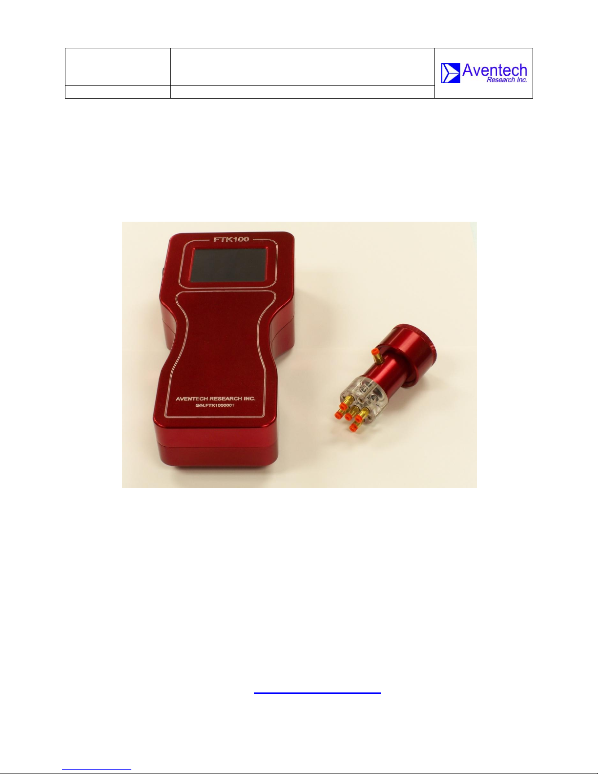
FTK100 FIELD TEST KIT
OPERATING MANUAL
Document-P/N:
FTK100-OM
FTK100 FIELD TEST KIT
OPERATING MANUAL
Document-P/N: FTK100-OM
110 Anne Street South, Unit 23
Barrie, Ontario, Canada L4N 2E3
© Aventech Research Inc. 2013. All Rights Reserved.
Aventech Research Inc.
Tel: (705) 722-4288
Fax: (705) 722-9077
Web: www.aventech.com
Page 2
Rev: 1.00
Date: 08.01.2013
Page: 2 of 31
FTK100 FIELD TEST KIT
OPERATING MANUAL
Document-P/N:
FTK100-OM
Date
Name
Signature
Function
08.01.2013
Bruce H. Woodcock
DE
Date
Name
Signature
Function
08.01.2013
Bruce H. Woodcock
DE
Date
Name
Signature
Function
08.01.2013
Bruce H. Woodcock
HD
Date
Name
Signature
Function
Issued
Checked
Approved
Customer Approval (as required)
Table of Functions
CUST Customer
DE Design Engineer
HD Head of Design Engineering
PM Production Manager
QM Quality Manager
© Aventech Research Inc. 2013. All Rights Reserved.
Page 3

Rev: 1.00
Date: 08.01.2013
Page: 3 of 31
FTK100 FIELD TEST KIT
OPERATING MANUAL
Document-P/N:
FTK100-OM
NOTICES
WARRANTY
Aventech Research Inc. products are warranted to be free from defects in material and
workmanship under normal use and service for a period of one year beginning on the
date of shipment. This warranty extends only to the original buyer or end-user customer
of an Aventech Research Inc. authorized reseller. This warranty does not apply to any
product which, in Aventech Research Inc’s opinion, has been misused, altered,
neglected, contaminated, or damaged by accident or abnormal conditions of operation
or handling.
Aventech Research Inc’s warranty obligation is limited, at Aventech Research Inc’s
option, to refund of the purchase price, free of charge repair, or replacement of a
defective product which is returned to within the warranty period.
To obtain warranty service, return the product to the nearest Aventech Research Inc.
authorized reseller, or direct to the address provided below:
Aventech Research Inc.
110 Anne Street South, Unit 23
Barrie, Ontario, Canada L4N 2E3
Tel: (705) 722-4288
Fax: (705) 722-9077
E-mail: [email protected]
Shipping costs to Aventech Research Inc. are the responsibility of the end customer
(FOB Destination). Aventech Research Inc. assumes no risk for damage in transit.
Following warranty repair, the product will be returned to Buyer, transportation prepaid
(FOB Destination). If Aventech Research Inc. determines that failure was caused by
neglect, misuse, contamination, alteration, accident, or abnormal condition of operation
or handling, including overvoltage failures caused by use outside the product’s specified
rating, or normal wear and tear of mechanical components, Aventech Research Inc. will
provide an estimate of repair costs and obtain authorization before commencing the
work. Following repair, the product will be returned to the Buyer transportation prepaid
and the Buyer will be billed for the repair and return transportation charges (FOB
Shipping Point).
Aventech Research Inc. warrants that product firmware will operate substantially in
accordance with its functional specifications. Aventech Research Inc. does not warrant
that firmware will be error free or operate without interruption.
© Aventech Research Inc. 2013. All Rights Reserved.
Page 4

Rev: 1.00
Date: 08.01.2013
Page: 4 of 31
FTK100 FIELD TEST KIT
OPERATING MANUAL
Document-P/N:
FTK100-OM
The material contained in this document is provided “as is,” and is subject to being
changed, without notice, in future editions. Further, to the maximum extent permitted by
applicable law, Aventech Research Inc. disclaims all warranties, either express or
implied, with regard to this manual and any information contained herein, including but
not limited to the implied warranties of merchantability and fitness for a particular
purpose. Aventech Research Inc. shall not be liable for errors or for incidental or
consequential damages in connection with the furnishing, use, or performance of this
document or of any information contained herein. Should Aventech Research Inc. and
the user have a separate written agreement with warranty terms covering the material in
this document that conflict with these terms, the warranty terms in the separate
agreement shall control.
THIS WARRANTY IS BUYER'S SOLE AND EXCLUSIVE REMEDY AND IS IN LIEU OF
ALL OTHER WARRANTIES, EXPRESS OR IMPLIED, INCLUDING BUT NOT LIMITED
TO ANY IMPLIED WARRANTY OF MERCHANTABILITY OR FITNESS FOR A
PARTICULAR PURPOSE. AVENTECH RESEARCH INC. SHALL NOT BE LIABLE
FOR ANY SPECIAL, INDIRECT, INCIDENTAL, OR CONSEQUENTIAL DAMAGES OR
LOSSES, INCLUDING LOSS OF DATA, ARISING FROM ANY CAUSE OR THEORY.
COPYRIGHT
© Aventech Research Inc. 2013. No part of this manual may be reproduced in any form
or by any means (including electronic storage and retrieval or translation into a foreign
language) without prior agreement and written consent from Aventech Research Inc. as
governed by Canadian and international copyright laws.
© Aventech Research Inc. 2013. All Rights Reserved.
Page 5

Rev: 1.00
Date: 08.01.2013
Page: 5 of 31
FTK100 FIELD TEST KIT
OPERATING MANUAL
Document-P/N:
FTK100-OM
Date
Issue
Page
Paragraph
Firmware
Revision
Comments
08.01.2013
1.00
All
All
Preliminary Draft
RECORD OF REVISIONS
© Aventech Research Inc. 2013. All Rights Reserved.
Page 6

Rev: 1.00
Date: 08.01.2013
Page: 6 of 31
FTK100 FIELD TEST KIT
OPERATING MANUAL
Document-P/N:
FTK100-OM
Date
Firmware
Revision
Comments
08.01.2013
1.10
Firmware version initial release
FIRMWARE REVISIONS
© Aventech Research Inc. 2013. All Rights Reserved.
Page 7

Rev: 1.00
Date: 08.01.2013
Page: 7 of 31
FTK100 FIELD TEST KIT
OPERATING MANUAL
Document-P/N:
FTK100-OM
TABLE OF CONTENTS
1.0 Introduction .......................................................................................................................... 9
2.0 Quick Start ..........................................................................................................................10
2.1 Verify the List of Supplied Items ....................................................................................................... 10
2.2 Charging the Unit .............................................................................................................................. 10
2.3 FTK100 and Calibration Fixture External Features ............................................................................ 10
2.4 Connecting the Calibration Fixture to the FTK100 ............................................................................ 12
2.5 Installing the Calibration Fixture ....................................................................................................... 12
2.6 Installing the Interface Cable ............................................................................................................ 13
2.7 Turning the Unit On .......................................................................................................................... 13
2.8 Resetting the Device ......................................................................................................................... 14
2.9 Turning the Device Off ...................................................................................................................... 14
3.0 Menu Features and Functions .............................................................................................15
3.1 Test .................................................................................................................................................... 15
3.1.1 IBIT ............................................................................................................................................ 16
3.1.2 CBIT .......................................................................................................................................... 16
3.1.3 Pressure Test ............................................................................................................................ 17
3.1.4 Magnetic Sensor ....................................................................................................................... 18
3.1.5 Accelerometer .......................................................................................................................... 19
3.1.6 GPS ........................................................................................................................................... 19
3.1.7 Thermistor ................................................................................................................................ 21
3.1.8 Humidity Sensor ....................................................................................................................... 22
Storing Data on USB ................................................................................................................................ 23
3.2 Settings ........................................................................................................................................... 25
3.2.1 Date and Time .......................................................................................................................... 25
3.2.2 Brightness ................................................................................................................................. 26
3.2.3 Screen Timeout ........................................................................................................................ 26
3.2.4 Default Settings ........................................................................................................................ 27
3.3 Maintenance ..................................................................................................................................... 28
© Aventech Research Inc. 2013. All Rights Reserved.
Page 8

Rev: 1.00
Date: 08.01.2013
Page: 8 of 31
FTK100 FIELD TEST KIT
OPERATING MANUAL
Document-P/N:
FTK100-OM
3.3.1 Device Under Test (DUT) Firmware Update .............................................................................. 28
3.3.2 FTK100 Firmware Update ................................................................................................... 29
4.0 Error Messages and Troubleshooting ..................................................................................30
5.0 Mechanical Drawing ............................................................................................................31
© Aventech Research Inc. 2013. All Rights Reserved.
Page 9

Rev: 1.00
Date: 08.01.2013
Page: 9 of 31
FTK100 FIELD TEST KIT
OPERATING MANUAL
Document-P/N:
FTK100-OM
1.0 Introduction
The Aventech Research Inc. FTK100 is an integrated Field Test Kit which provides
an extensive set of testing functions to verify the operational status of Aventech’s
line of airborne air-data, GPS and inertial system products. FTK100 test
functionality includes:
• Validation and calibration of pressure channel measurements for both pitot-
static and five-hole probes including barometric, pitot-static, angle-of-attack
and angle-of-sideslip pressures
• Display of three-axis accelerometer and rate sensor measurements for
validation of inertial subsystem
• Display of GPS receiver data for validation of GPS subsystem
• Display of three-axis magnetic sensor measurements
• Display of temperature and humidity measurements for validation of
environmental / meteorological subsystem
• Reporting of IBIT status
• Reporting of CBIT status
• Firmware update capability for both the FTK100 unit itself as well as the
attached instrumentation
Features of the FTK100 include:
• 3.5” Colour QVGA (320 X 240) TFT Touch-screen LCD display
• Intuitive easy-to-use menu driven operating system
• Integrated pump, plenum and valve system for provision of test pressures
• High-speed CAN AERO port for communication with the device under test
• One 15 psi pressure port for testing / calibrating barometric sensors
• Five 1 psi pressure ports for testing / calibrating pitot-static, angle-of-attack
and sideslip pressures
• Integrated USB port for storage of data files and test reports which can then
be easily transported to other computer systems
• Internal Real-Time Clock (RTC) for time stamping validation / calibration
reports
• Integrated Lithium Ion battery providing up to 10 hours run time
• Integrated battery charging electronics with 100-240 50-60 Hz VAC plug-in
wall charger
• Integrated battery gauge for reporting battery charge status
The FTK100 interfaces with a variety of air-data probe calibration fixtures and can
be utilized as a standard pressure calibration device. FTK100 full functionality exists
for the Aventech Research Inc. ARIM200 Air Data Probe and ARIM320 Air / Inertial
/ Meteorological Digital Data System.
© Aventech Research Inc. 2013. All Rights Reserved.
Page 10
Rev: 1.00
Date: 08.01.2013
Page: 10 of 31
FTK100 FIELD TEST KIT
OPERATING MANUAL
Document-P/N:
FTK100-OM
2.0 Quick Start
One of the first things you will want to do with your FTK100 Field Test Kit is to
become familiar with its external controls and connections. We have written the
exercises in this chapter to prepare your FTK100 for use and help you get familiar
with some of its operations.
2.1 Verify the List of Supplied Items
The first thing you will want to do is verify that you have received the following items
with your Field Test Kit. If anything is missing, please contact your approved reseller
or Aventech Research Inc. directly.
One hand-held FTK100 Field Test Kit control unit
One Calibration Fixture
Six lengths of plastic tubing
One wall-mount 12.8 VDC output power supply for charging battery
This Operating Manual
2.2 Charging the Unit
Although the unit will have been fully charged before it left our facility, it is
recommended that you charge the unit before its first use.
2.3 FTK100 and Calibration Fixture External Features
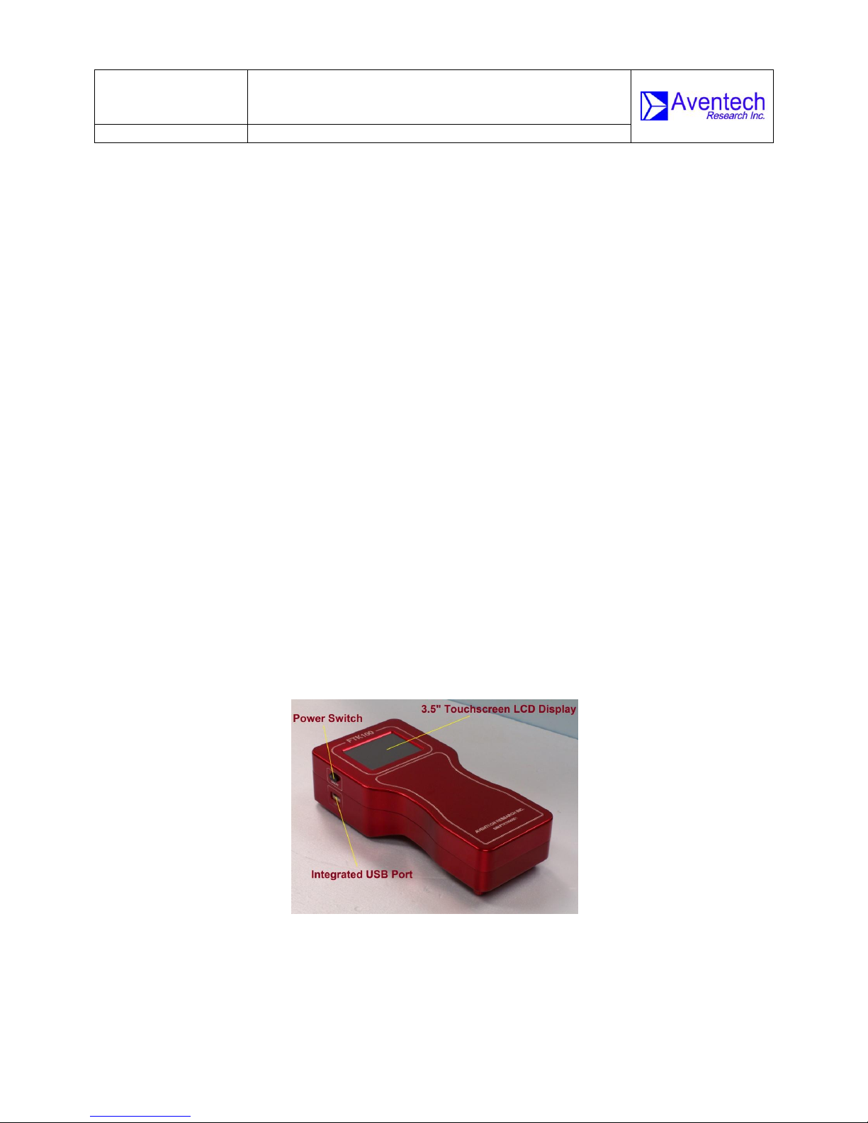
Figure 1: FTK100 Front and Left Hand Side Panel Features
© Aventech Research Inc. 2013. All Rights Reserved.
Page 11
Rev: 1.00
Date: 08.01.2013
Page: 11 of 31
FTK100 FIELD TEST KIT
OPERATING MANUAL
Document-P/N:
FTK100-OM
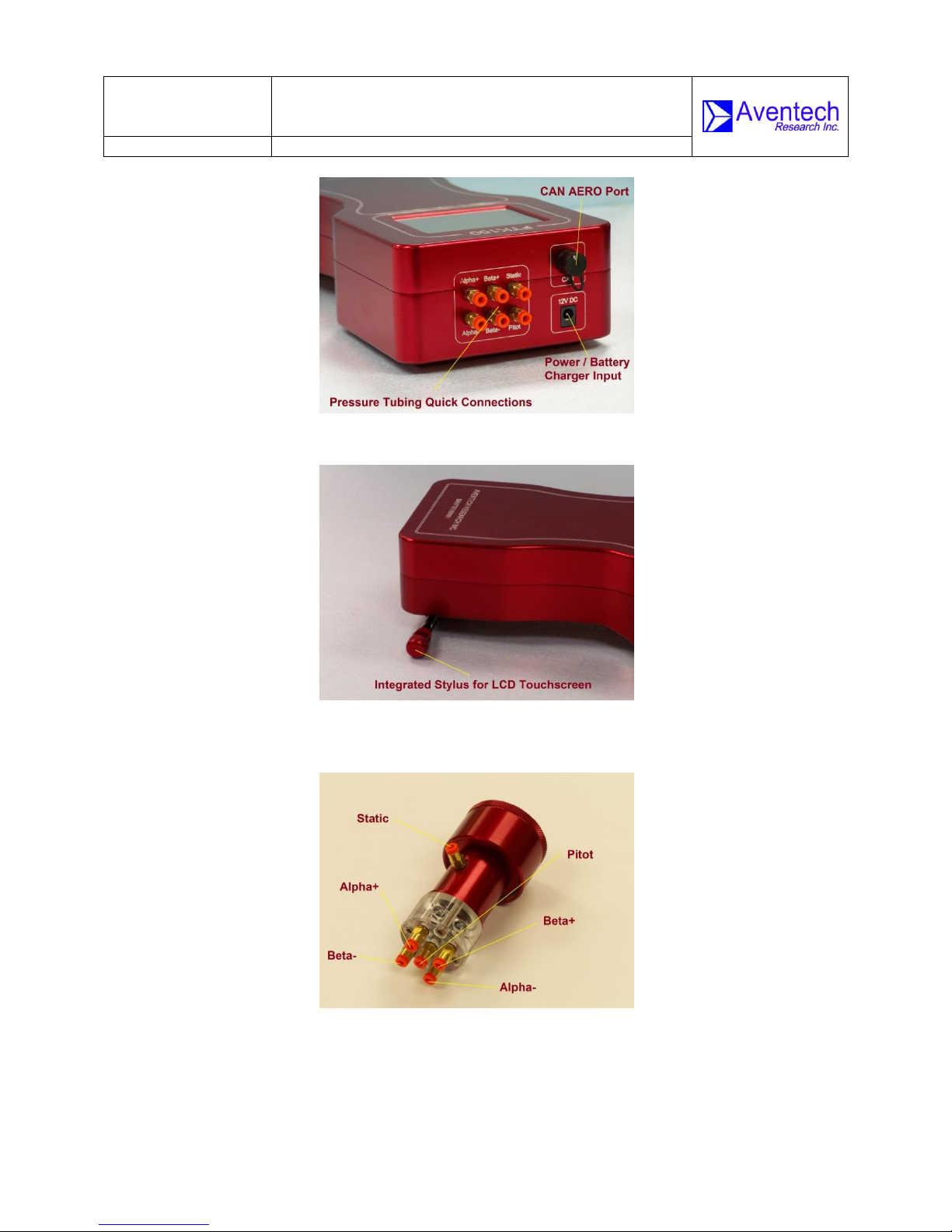
Figure 2: FTK100 Top Panel Features
Figure 3: Integrated Stylus for use with LCD Touchscreen
Figure 4: Typical Calibration Fixture Tubing Connections (ARI320 Version Shown)
© Aventech Research Inc. 2013. All Rights Reserved.
Page 12

Rev: 1.00
Date: 08.01.2013
Page: 12 of 31
FTK100 FIELD TEST KIT
OPERATING MANUAL
Document-P/N:
FTK100-OM
2.4 Connecting the Calibration Fixture to the FTK100
This section describes how to connect the calibration fixture to the FTK100 control
module.
The FTK100 supports calibration fixtures designed to test pressures on standard
pitot-static probes and five-hole probes. A calibration fixture designed to test the
five-hole probe integrated into the ARIM320 is shown in Figure 4. For testing the
more common pitot-static probes, tubing is only required to be connected between
the pitot tubing connector on the forward face of the calibration fixture, and the static
tubing connector furthest aft on the side of the calibration fixture. If a five-hole probe
is being tested, as shown in Figure 4, tubing must also be connected to the angleof-attack (alpha) connectors in the vertical plane and sideslip connectors in the
horizontal plane. Please note that the calibration five-hole probe calibration fixtures
are typically designed so that the static connector is on the same side as the Alpha+
connector. This allows the user to orient the calibration fixture correctly when
installing it on the probe.
Both the FTK100 control module and Aventech Research Inc. calibration fixtures
utilize 1/8” OD quick connect / disconnect fittings to interface to the interconnecting
pressure tubing. To install the tubing simply insert it as far as possible into the fitting
and it will lock in place. To disconnect, push down on the orange collar on the fitting
and pull the tubing out.
Six lengths of 1/8” OD tubing will have been provided with your field test kit which
should be installed between the pressure connections show on the calibration
fixture in Figure 4 and the labeled input ports on the FTK100 shown in Figure 2.
2.5 Installing the Calibration Fixture
For pitot-static probes, orientation of the calibration fixture is not important however,
for five-hole probes it is critical. As described in Section 2.5, the static pressure
fitting is typically located on the same side as the alpha+ pressure fitting.
Install the calibration fitting onto the measurement boom by sliding it over the boom
while insuring the static pressure fitting is pointing straight up. This will insure that
the remaining pressure fittings are oriented correctly relative to the pressure ports
on the measurement boom. Slide the fixture as far as it will go onto the boom and
then apply a small amount of longitudinal force to the fixture to compress the Orings against the nose of the boom and seal off the pressure ports to the calibration
fixture. While applying this force, rotate the collar located at the rear of the
calibration fixture clockwise, when looking at the front of the fixture, gently to lock
the fixture onto the probe boom.
© Aventech Research Inc. 2013. All Rights Reserved.
Page 13
Rev: 1.00
Date: 08.01.2013
Page: 13 of 31
FTK100 FIELD TEST KIT
OPERATING MANUAL
Document-P/N:
FTK100-OM
Some calibration fixtures will be manufactured with a clear acrylic front to allow the
user to observe that the pressure inputs in the calibration fixture are correctly
oriented with the pressure ports on the probe.
2.6 Installing the Interface Cable
Install the CAN Interface cable between the FTK100 and Device Under Test (DUT).
2.7 Turning the Unit On
To begin a test both the DUT and the FTK100 have to be turned on in that order. To
power the FTK100 depress and release the power switch shown in Figure 1.
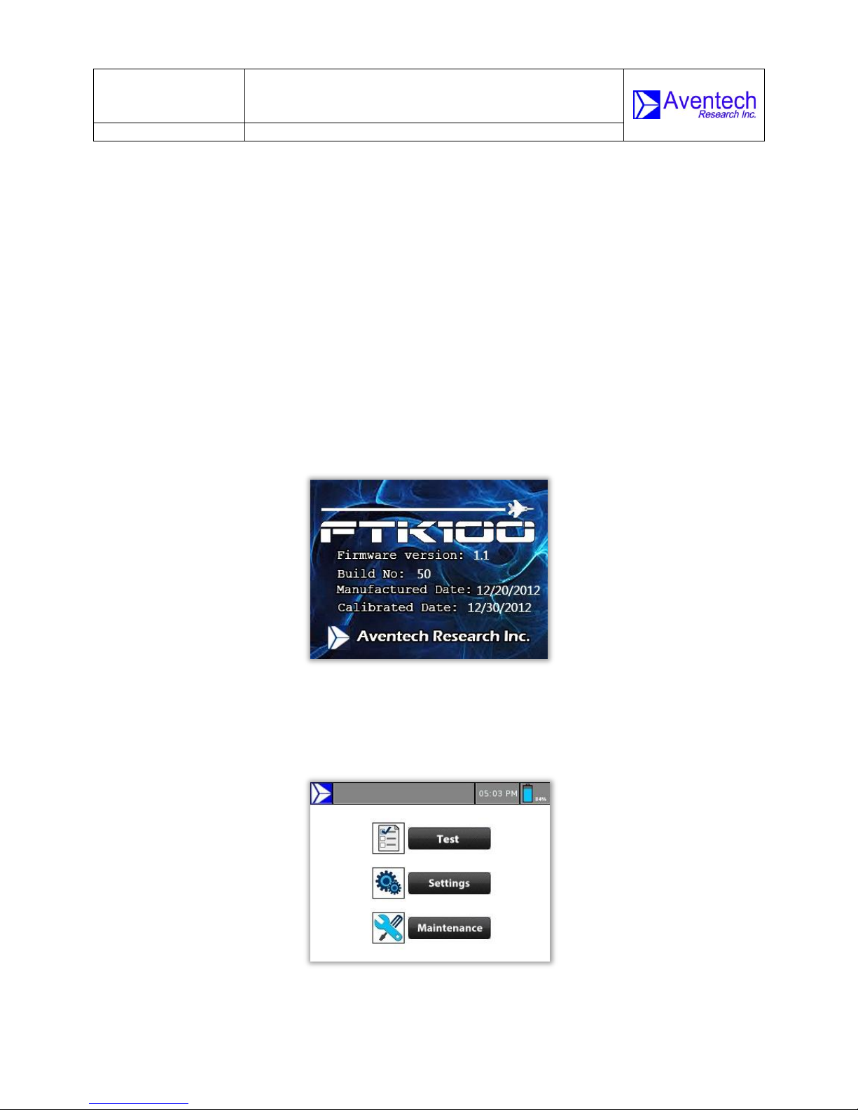
As the unit boots up and runs its internal self-tests the splash screen shown in
Figure 5 below will appear showing the unit`s current firmware version and build
number, manufacturing date and calibration date.
At completion of the start-up procedure the main FTK100 operating system menu
window will appear as shown in Figure 6 below.
Figure 6: FTK100 Operating System Main Menu Window
© Aventech Research Inc. 2013. All Rights Reserved.
Figure 5: FTK100 Splash Screen
Page 14

Rev: 1.00
Date: 08.01.2013
Page: 14 of 31
FTK100 FIELD TEST KIT
OPERATING MANUAL
Document-P/N:
FTK100-OM
The FTK100 operating system windows consists of a status bar and display area
with menu buttons to access and run various test, settings, and maintenance
functions programmed into the unit.
The status bar appears in each menu window providing any necessary status
information, the current time from the real-time clock just to the right of centrescreen and the battery charge status in the right-hand corner. Home button at the
top left corner can be used to navigate to the main window from any other windows.
2.8 Resetting the Device
The device can be reset at any point by pressing and holding the on/off button for
more than five seconds and releasing it once the touch screen shuts down.
Note: All test results will be erased once the device is reset.
2.9 Turning the Device Off
To shut down the device, the on/off push button should be pressed and held for one
to two seconds and released.
Note: The device cannot be turned off while it is in the test mode. In order to turn it
off, you have to exit from the test mode and make sure the screen is showing either
the home/main page or any other subpages such as test, settings, or maintenance.
© Aventech Research Inc. 2013. All Rights Reserved.
Page 15
Rev: 1.00
Date: 08.01.2013
Page: 15 of 31
FTK100 FIELD TEST KIT
OPERATING MANUAL
Document-P/N:
FTK100-OM
3.0 Menu Features and Functions
3.1 Test
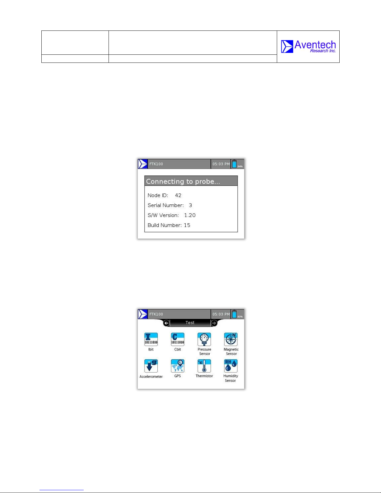
After pressing the Test button on the main menu, the FTK100 will immediately
connect with the DUT, download and subsequently display the CAN AERO Node ID
number, serial number and firmware version of the DUT.
Figure 7: Connecting to DUT and Obtaining Probe Information
The DUT Node ID, Serial number and software ID data are displayed for three
seconds, after which the Test Menu is displayed:
Figure 8: Test Window
© Aventech Research Inc. 2013. All Rights Reserved.
Page 16
Rev: 1.00
Date: 08.01.2013
Page: 16 of 31
FTK100 FIELD TEST KIT
OPERATING MANUAL
Document-P/N:
FTK100-OM
3.1.1 IBIT
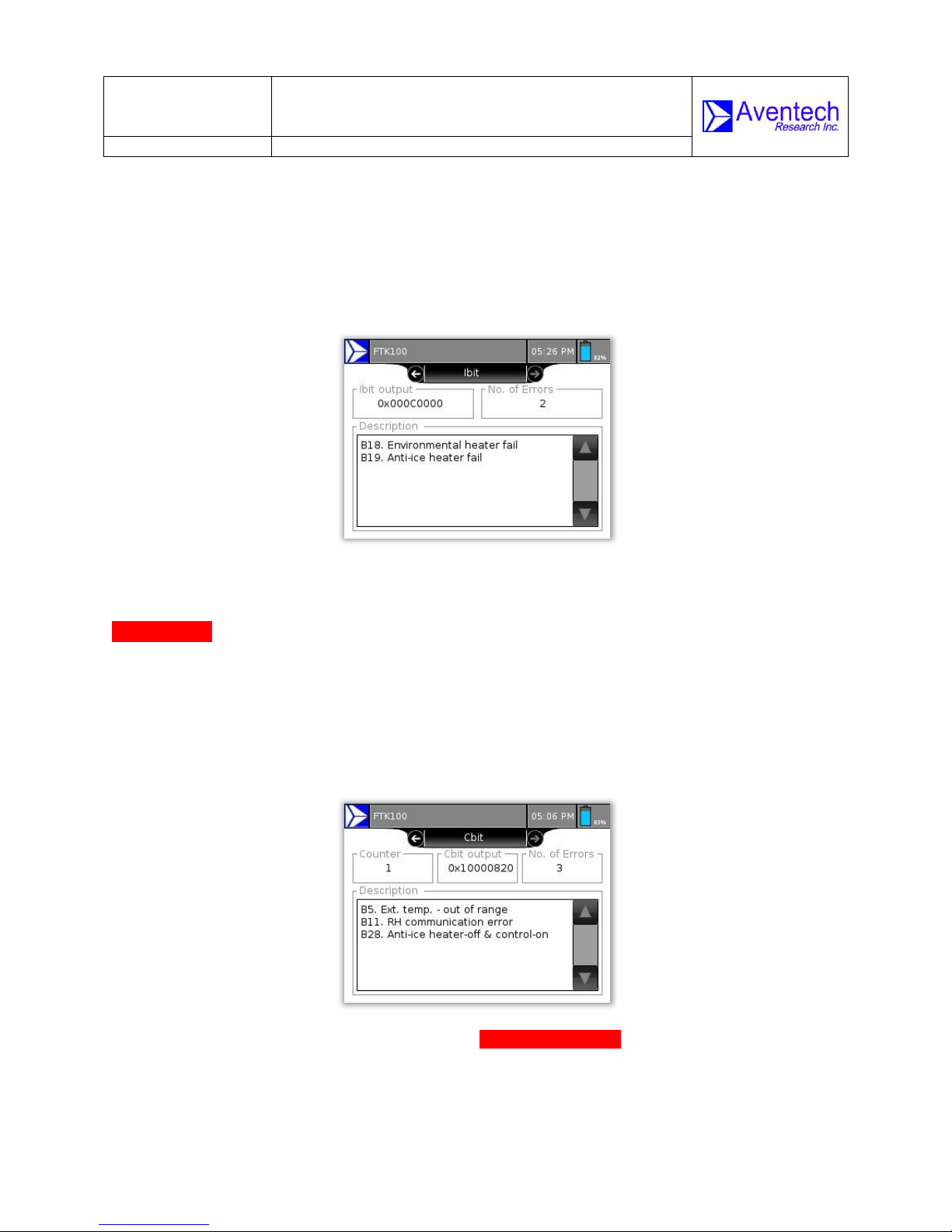
The FTK100 will send an IBIT request to the DUT and the 32-bit status word sent
in reply from the DUT will be displayed in hexadecimal format. To assist
interpretation, the output includes text descriptions of each non-zero bit occurring
in the status word, each representing a particular error condition.
3.1.2 CBIT
CBIT data is continuously generated by the DUT under normal operation. The
FTK100 sends a request at 1Hz to continuously receive and monitor the latest
CBIT values being generated by the system. Two different CBIT values will be
output along with text-based descriptions of all non-zero bits denoting various
error conditions.
Figure 9: Ibit Test
© Aventech Research Inc. 2013. All Rights Reserved.
Figure 10: Cbit Test (change the image)
Page 17
Rev: 1.00
Date: 08.01.2013
Page: 17 of 31
FTK100 FIELD TEST KIT
OPERATING MANUAL
Document-P/N:
FTK100-OM
3.1.3 Pressure Test
This feature will perform a pressure test of all five pressure ports on the tip of the
air-data probe and the ring of static-pressure ports around its circumference.
This test can be performed only if the appropriate probe adapter is firmly secured
to the DUT and is connected to the FTK using the supplied tubing.
Immediately after the Pressure Test is selected, the internal pump will begin to
pressurize the system to approximately 3000Pa. If any leaks are present, as
would occur if the probe adapter is not properly in place, the pump will continue
to run until a timeout error is generated if the target pressure is not reached
within 6 seconds. If the no leaks occur, the pump will bring the system up to test
pressure in approximately 1 second. The following window will then be displayed:
Figure 11: Pressure Test Layout
After a 5 second settling period, valves will be activated to introduce the test
pressure to the AOA+ (ALPHA+) pressure port. The FTK100 will read the
pressure data sensed by the DUT across the CAN AERO connection and record
data from its own internal reference pressure sensor for a period of five seconds.
After this sampling period, the valves are switched to disconnect the AOA+ port
and return it to ambient atmospheric pressure, and simultaneously connect the
internal pressure plenum to the AOA- (ALPHA-) port. During the following 5
second settling period, the pump is given ability to re-engage and recharge the
plenum if necessary. If this occurs, a further 5s settling period is introduced
before data is collected from both the DUT and reference pressure sensor. This
process continues through all pressure ports in the following order: AOA+, AOA-,
AOS+ (BETA+), AOS- (BETA-), Pitot-Static. After data has been collected for the
pitot-static test, the valves switch to change the direction of air-flo w between the
pump and internal plenum so as to generate a vacuum. The pump runs and
takes the plenum pressure down to approximately 90kPa. The static pressure
© Aventech Research Inc. 2013. All Rights Reserved.
Page 18
Rev: 1.00
Date: 08.01.2013
Page: 18 of 31
FTK100 FIELD TEST KIT
OPERATING MANUAL
Document-P/N:
FTK100-OM
port is then activated and now the internal reference barometric sensor is
sampled concurrently with data from the DUT access across the CAN AERO
network connection.
The status bar will display status information as the test progresses through all
stages.
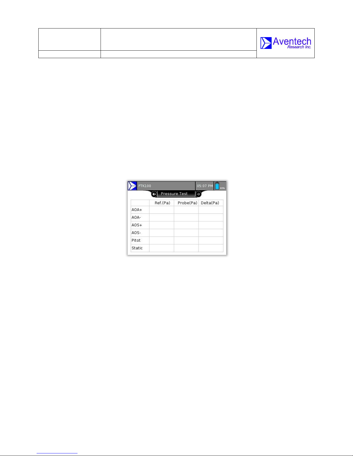
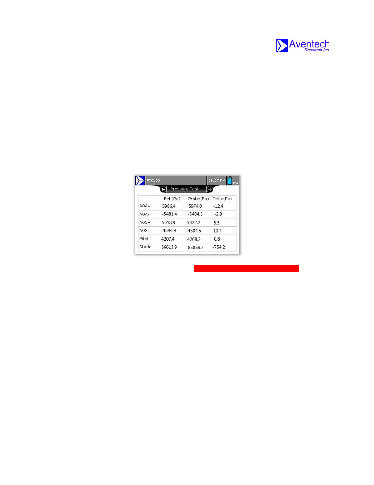
Once the test is complete, mean values are computed from the approximately
150 data points sampled during each stage of the test. Mean values from the
reference sensors, the DUT and the differences between them are displayed in a
tabular format:
Figure 12: Sample Pressure Test Results(change the image – static is wrong)
3.1.4 Magnetic Sensor
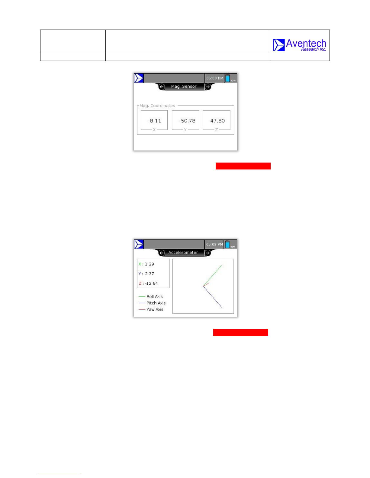
Magnetic sensor test results will show the magnetic coordinates which are generated by
the magnetic sensor at 1 Hz frequency. A compass on the screen will indicate the
approximate heading direction of the DUT.
© Aventech Research Inc. 2013. All Rights Reserved.
Page 19
Rev: 1.00
Date: 08.01.2013
Page: 19 of 31
FTK100 FIELD TEST KIT
OPERATING MANUAL
Document-P/N:
FTK100-OM
Figure 13: Magnetic Sensor Test Results(change the image)
3.1.5 Accelerometer
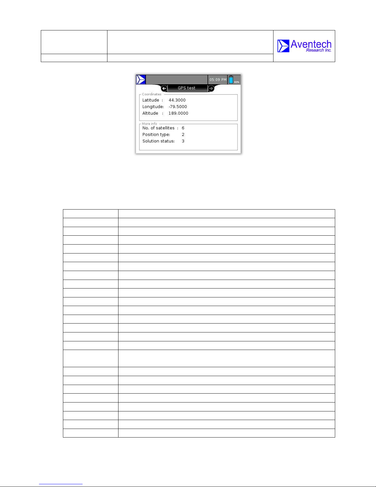
Accelerometer test results will show the raw data from roll (x), pitch (y), and yaw
(z) accelerometers. A 3D animation of each axis will also be displayed on the
screen to compare the results with DUT’s orientation.
3.1.6 GPS
Figure 14: Accelerometer Test Results (change the image)
GPS test results show the location of the device under test such as latitude,
longitude, and altitude. In addition, it also provides number of satellites that are
used to obtain the results, position type, and solution status.
© Aventech Research Inc. 2013. All Rights Reserved.
Page 20
Rev: 1.00
Date: 08.01.2013
Page: 20 of 31
FTK100 FIELD TEST KIT
OPERATING MANUAL
Document-P/N:
FTK100-OM
Position Type
Description
0
No solution
1
Position has been fixed by FIX POSITION command
2
Position has been fixed by the FIX HEIGHT/AUTO command
8
Velocity computed using instantaneous Doppler
16
Single point position
17
Pseudorange differential solution
18
Solution calculated using corrections from an SBAS
19
Propagated by a Kalman filter without new observations
20
OmniSTAR VBS position
32
Floating L1 ambiguity solution
33
Floating ionospheric-free ambiguity solution
34
Floating narrow-lane ambiguity solution
48
Integer L1 ambiguity solution
49
Integer wide-lane ambiguity solution
50
Integer narrow-lane ambiguity solution
51
RTK status where the RTK filter is directly initialized from the
INS filter
52
INS calculated position corrected from the antenna
53
INS pseudorange single point solution – no DGPS corrections
54
INS pseudorange differential solution
55
INS RTK floating point ambiguities solution
56
INS RTK fixed ambiguities solution
64
OmniSTAR HP/XP position
65
OmniSTAR XP position
66
Position solution using CDDPS correction
Figure 15: GPS Test Results
Position type and description are shown in the following table:
Table 1: Position Type and Description
© Aventech Research Inc. 2013. All Rights Reserved.
Page 21

Rev: 1.00
Date: 08.01.2013
Page: 21 of 31
FTK100 FIELD TEST KIT
OPERATING MANUAL
Document-P/N:
FTK100-OM
Solution
Status
Description
0
Solution computed
1
Insufficient observations
2
No convergence
3
Singularity at parameters matrix
4
Covariance trace exceeds maximum(trace > 1000m)
5
Test distance exceeded(maximum of 3 rejections if
distance>10km)
6
Not yet converged from cold start
7
Height or velocity limits exceeded
8
Variance exceeds limits
9
Residuals are too large
10
Delta position is too large
11
Negative variance
12
Reserved
13
Large residuals make position unreliable
14-17
INS solution status values
18
When a FIX POSITION command is entered, the receiver
computes its own position and determines if the fixed position is
valid
19
The fixed position, entered using the FIX POSITION command,
is not valid
20
Position type is unauthorized - HP or XP on a receiver not
authorized for it
Solution status is broadcasted by GPS to indicate the status and errors found.
Following table describes the status and descriptions.
Table 2: Solution Status and Description
3.1.7 Thermistor
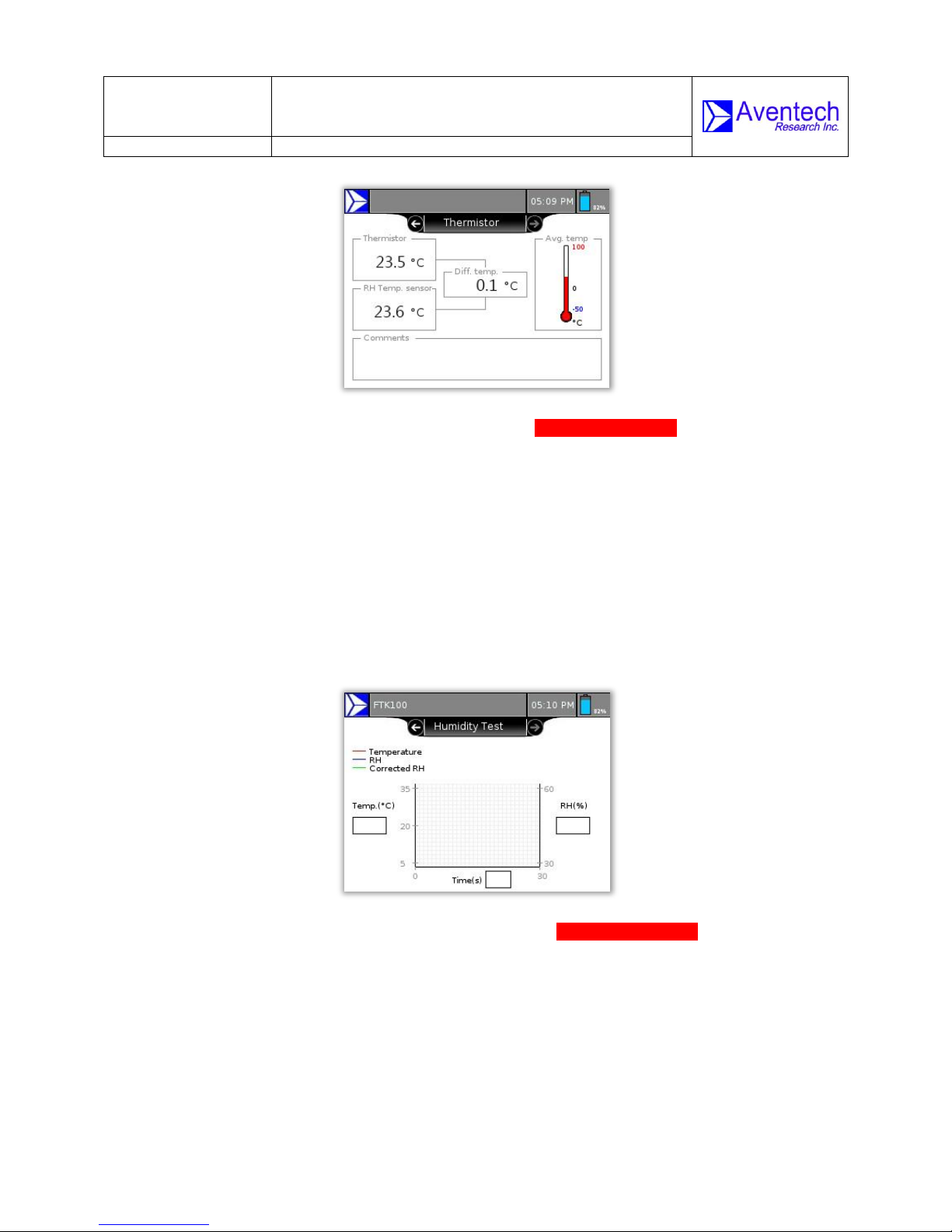
In this test mode, the temperature readings from the thermistor and built-in temperature
sensor in the RH sensor will be compared. The difference between these two
temperatures and average temperature will also be displayed with comments (if any).
© Aventech Research Inc. 2013. All Rights Reserved.
Page 22
Rev: 1.00
Date: 08.01.2013
Page: 22 of 31
FTK100 FIELD TEST KIT
OPERATING MANUAL
Document-P/N:
FTK100-OM
Figure 16: Thermistor Test Results (change the image)
3.1.8 Humidity Sensor
Figure 17: Humidity Sensor Test Results (change the image)
© Aventech Research Inc. 2013. All Rights Reserved.
Page 23
Rev: 1.00
Date: 08.01.2013
Page: 23 of 31
FTK100 FIELD TEST KIT
OPERATING MANUAL
Document-P/N:
FTK100-OM
Storing Data on USB
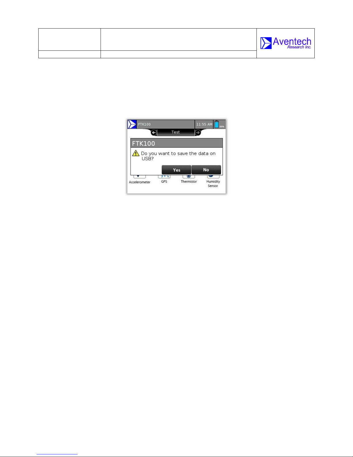
When exiting from the test mode, a dialog box will give an option to store the test results
on a USB.
Figure 18: Dialog Box Confirms To Store the Data on USB
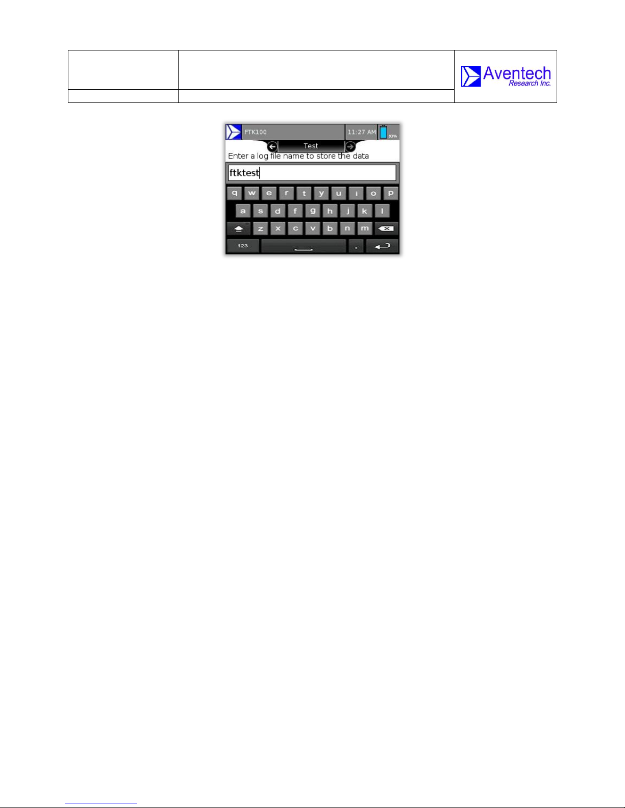
The user can enter a file name to store the data using the keyboard that can be
accessed by pressing the ‘Yes’ button in the above dialog box. The file name must
contain less than nine characters. The device will create a folder and name it as
‘FTK100’ (if the folder already exists, then it will select that folder) to store all the test
results. Once the confirmation message is appeared, the USB can be removed from the
port.
Note: Removing the USB while storing data might create a corrupted file or cause
problems with opening the files.
Note: All the test results will be erased if the ‘No’ button is clicked in the above dialog
box.
© Aventech Research Inc. 2013. All Rights Reserved.
Page 24
Rev: 1.00
Date: 08.01.2013
Page: 24 of 31
FTK100 FIELD TEST KIT
OPERATING MANUAL
Document-P/N:
FTK100-OM
Figure 19: Keyboard to Enter Log File Name
© Aventech Research Inc. 2013. All Rights Reserved.
Page 25
Rev: 1.00
Date: 08.01.2013
Page: 25 of 31
FTK100 FIELD TEST KIT
OPERATING MANUAL
Document-P/N:
FTK100-OM
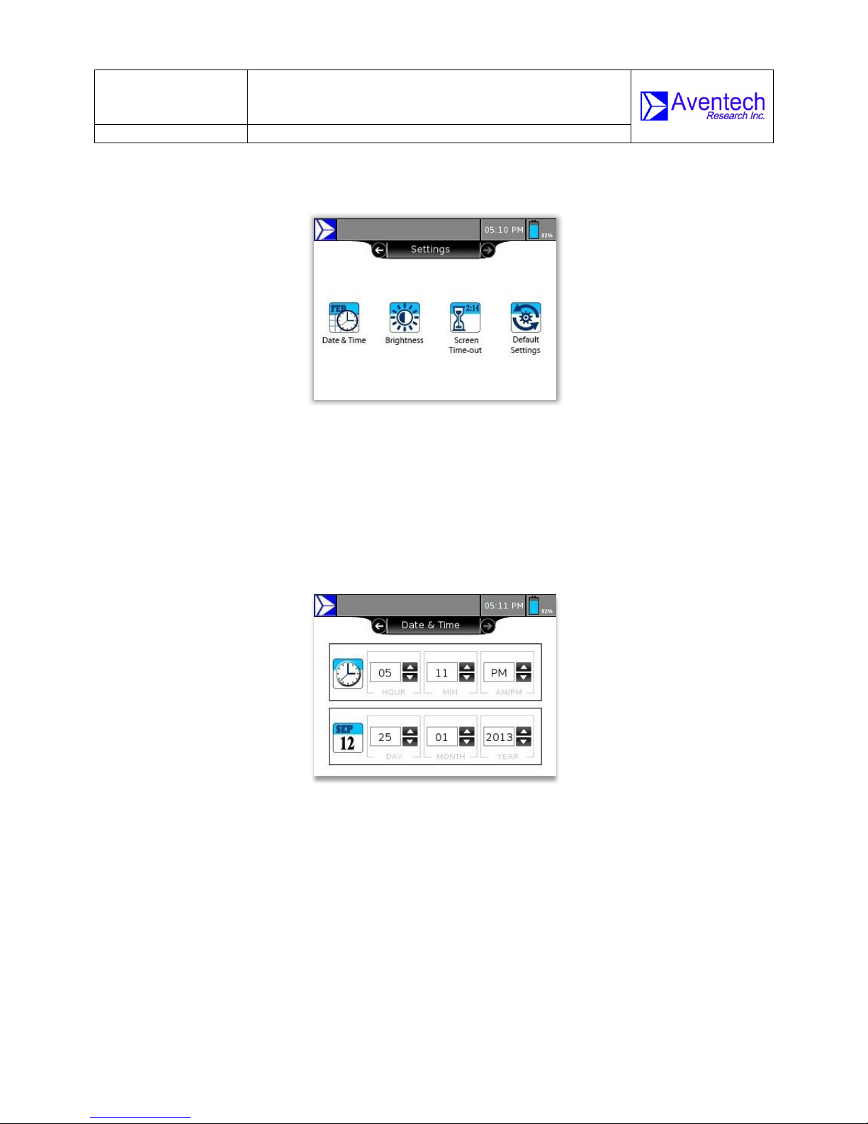
3.2 Settings
3.2.1 Date and Time
Sets the system date and time.
Figure 20: Settings Window
© Aventech Research Inc. 2013. All Rights Reserved.
Figure 21: Date and Time
Page 26
Rev: 1.00
Date: 08.01.2013
Page: 26 of 31
FTK100 FIELD TEST KIT
OPERATING MANUAL
Document-P/N:
FTK100-OM
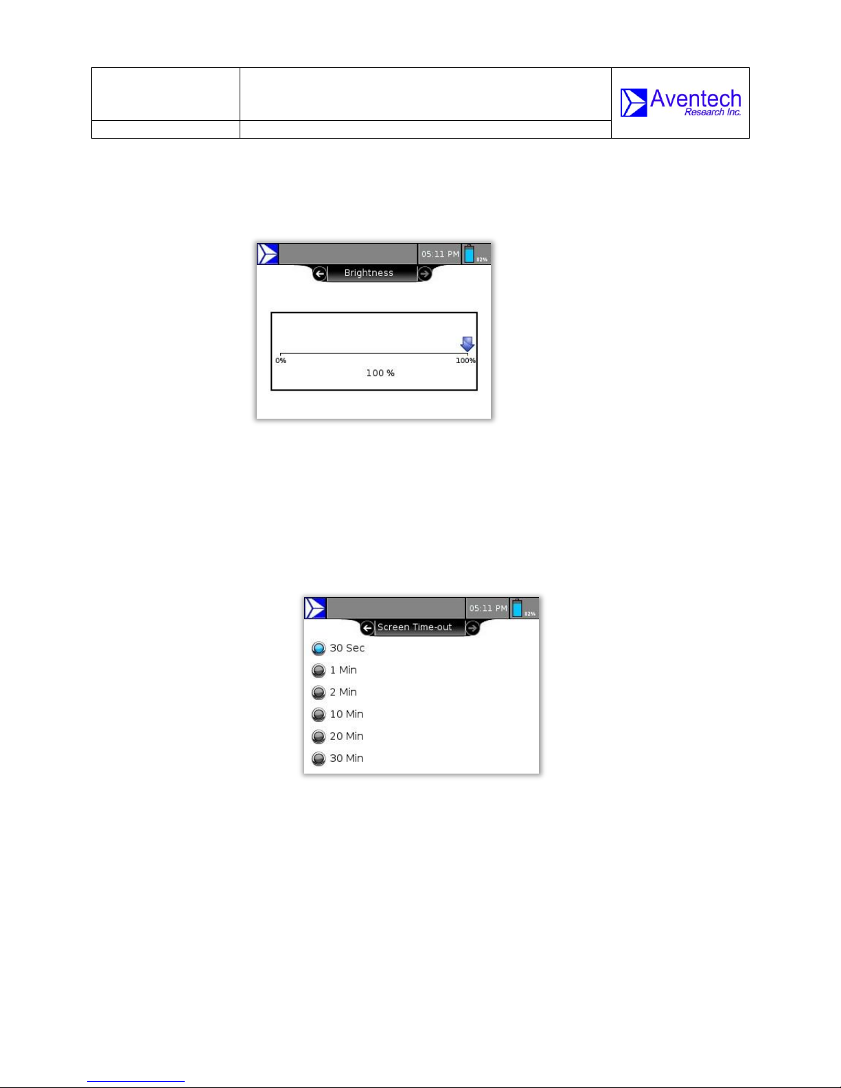
3.2.2 Brightness
Sets the screen brightness.
3.2.3 Screen Timeout
Sets screen timeout (30 seconds to 30 minutes).
Figure 22: Brightness
Figure 23: Screen Timeout
© Aventech Research Inc. 2013. All Rights Reserved.
Page 27
Rev: 1.00
Date: 08.01.2013
Page: 27 of 31
FTK100 FIELD TEST KIT
OPERATING MANUAL
Document-P/N:
FTK100-OM
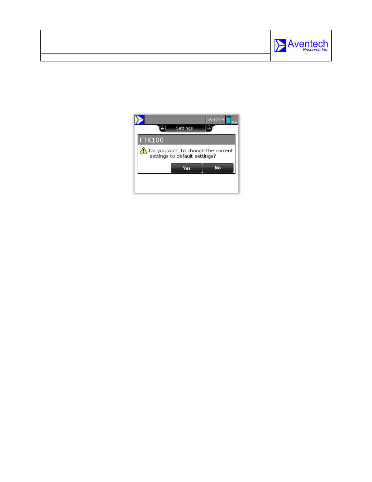
3.2.4 Default Settings
Restores system default settings.
Figure 24: Dialog box to confirm the changes in settings
© Aventech Research Inc. 2013. All Rights Reserved.
Page 28
Rev: 1.00
Date: 08.01.2013
Page: 28 of 31
FTK100 FIELD TEST KIT
OPERATING MANUAL
Document-P/N:
FTK100-OM
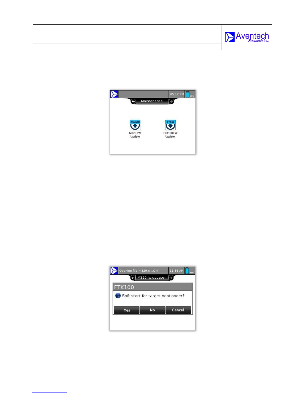
3.3 Maintenance
Maintenance window is used to update FTK100 and DUT firmware through a
FLASH memory drive.
Figure 25: Maintenance Window
3.3.1 Device Under Test (DUT) Firmware Update
Icons with DUT name, such as M320, update the DUT firmware from a FLASH
memory drive that is in the USB port.
For example, to update the M320 firmware, the firmware file has to be placed in
the root (not in any folders) of USB drive. When ‘M320 FW Update’ icon is
pressed, a dialog box will give an option to soft-start the DUT boot loader. The
DUT boot loader can be triggered to start firmware updating process by pressing
the ‘Yes’ button in the dialog box. Alternatively, the firmware updating process
can be done by pressing ‘No’ and manually turning the DUT power off and on.
Figure 26: Dialog box to Start Firmware Update
© Aventech Research Inc. 2013. All Rights Reserved.
Page 29
Rev: 1.00
Date: 08.01.2013
Page: 29 of 31
FTK100 FIELD TEST KIT
OPERATING MANUAL
Document-P/N:
FTK100-OM
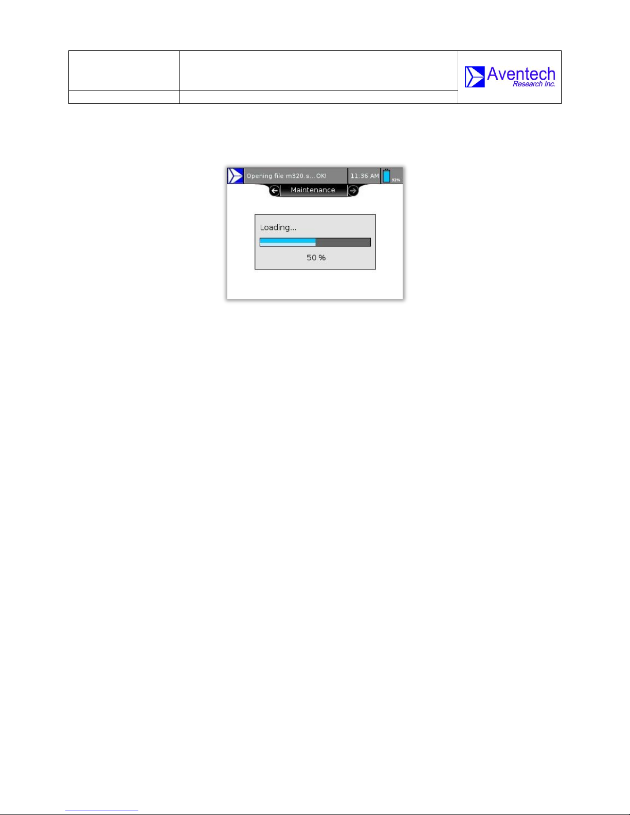
Following progress bar will appear on the screen to show the status of the
firmware updating process. Once the updating process is done, a confirmation
message will ensure that the firmware is successfully updated.
Figure 27: Progress Bar Showing the Status of Firmware Update Process
Note: Do not change the name of the firmware file.
3.3.2 FTK100 Firmware Update
Updates the FTK100 firmware from a FLASH memory drive inserted in the USB
port.
© Aventech Research Inc. 2013. All Rights Reserved.
Page 30

Rev: 1.00
Date: 08.01.2013
Page: 30 of 31
FTK100 FIELD TEST KIT
OPERATING MANUAL
Document-P/N:
FTK100-OM
Error Messages
Troubleshooting
No reply / No response
Check if the CAN cable between DUT and FTK100
is connected properly.
Make sure the DUT is connected to the power
supply.
If the problem continues, restart FTK100 and the
DUT.
Time-out error
This error occurs if the test results are not obtained
within a certain time limit.
Ensure proper CAN connection between DUT and
FTK100.
If there is any leakage inside the calibration fixture,
time-out error will be displayed during the pressure
test as the device can’t obtain the pressure results
within the time limit. Gently push the calibration
fixture further until all the O-rings in the fixture are
fully engaged with the boom.
Error in detecting USB
Insert the USB if it is not already in the port. If the
device generates this error messages while USB is
in the port, then remove and reinsert the USB. If
the problem continues, reboot FTK100 and try
again.
Note: Do NOT insert the USB while FTK100 is
starting. Insert before pressing the ON/OFF button
or after the main window comes up.
Invalid file name
This error occurs when the user enters file name
that contains invalid characters to store the data.
The valid file name must contain uppercase letters,
lowercase letters, numbers and one of the
following characters:
$ % ‘ - _ @ ~ ! ( ) { } ^ # &
4.0 Error Messages and Troubleshooting
FTK100 displays error messages when it has communication problems with other
devices such as USB drive and device under test. Following table summarizes the
errors and how to troubleshoot the problems.
Table 3: Troubleshooting Tips for the Error Messages Generated By FTK100
© Aventech Research Inc. 2013. All Rights Reserved.
Page 31
Rev: 1.00
Date: 08.01.2013
Page: 31 of 31
FTK100 FIELD TEST KIT
OPERATING MANUAL
Document-P/N:
FTK100-OM
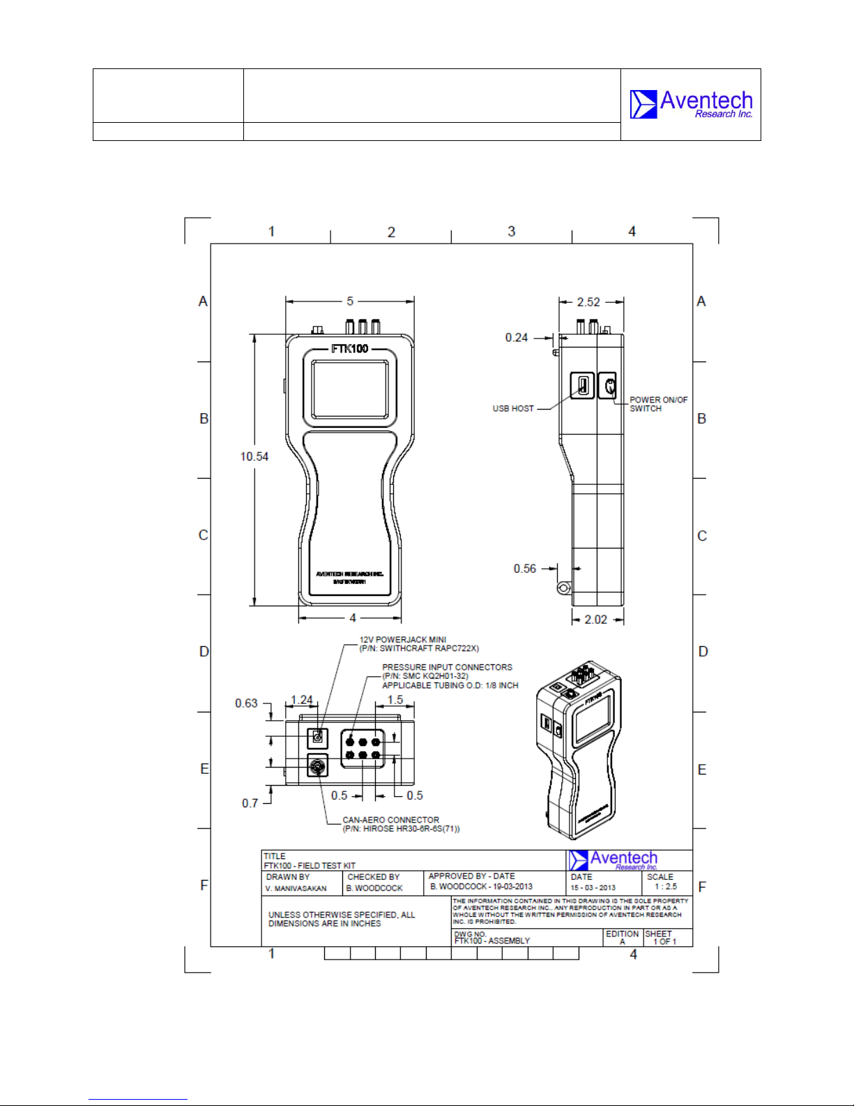
5.0 Mechanical Drawing
© Aventech Research Inc. 2013. All Rights Reserved.
 Loading...