

Avedro, Inc.
Mosaic® System
Operator’s Manual
Copyright 2019. All Rights Reserved.
Printed in U.S.A.
Mosaic Operator’s Manual Rev F
ML-00023

Patents, Trademarks, Copyrights
The Mosaic System may be covered by one or more patent applications
issued or pending in the United States and worldwide.
“Mosaic” and the Avedro logo design are registered trademarks or
trademarks of Avedro, Inc. All software and documentation are subject to
Avedro, Inc. copyrights. All rights reserved 2019.
Microsoft and Windows are registered trademarks and trademarks,
respectively, of Microsoft Corporation. Any other trademarks or service
marks contained within this manual are the property of their respective
owners.
For more information, contact: Your Local Avedro-authorized
distributor
Avedro, Inc.
201 Jones Road
Waltham, MA 02451
Authorized Representative
EMERGO EUROPE
Prinsessegracht 20
2514 AP, The Hague
The Netherlands
Phone: +31.70.345.8570
Fax: +31.70.346.7299
0086
Mosaic Operator’s Manual Rev F
ML-00023

Table of Contents
1 Foreword .................................................................................................................................... 1
Intended Use of Manual ................................................................................................................ 1
Intended Use / Indications for Use .......................................................................................... 1
Essential Requirements ................................................................................................................. 1
Design Change Disclaimer ........................................................................................................... 1
Reproduction Disclaimer ............................................................................................................. 2
User Operation Assistance Statement ................................................................................. 2
Contraindications, Warnings, and Cautions ....................................................................... 2
1.7.1 Contraindications ................................................................................................................ 2
1.7.2 Warnings and Cautions ................................................................................................... 2
1.7.3 Electrical Safety Warnings ............................................................................................ 3
1.7.4 Radiation Safety Warnings ........................................................................................... 5
Patient Safety .................................................................................................................................... 6
Additional Safety Considerations ........................................................................................... 6
FCC Compliance Notice ............................................................................................................... 6
2 Introduction .............................................................................................................................. 8
System Overview ............................................................................................................................ 8
2.1.1 Major Components ............................................................................................................. 9
2.1.2 Disposables ......................................................................................................................... 10
2.1.3 Mosaic System Labels .....................................................................................................11
2.1.4 Frequently Used Functions ........................................................................................ 12
3 System Operation .................................................................................................................. 13
Touchpad/Keyboard Use .......................................................................................................... 13
UV Energy (Dose) ......................................................................................................................... 14
4 System Set Up ........................................................................................................................ 15
Important Steps before Turning on the System ........................................................... 15
Preparing the System .................................................................................................................. 15
Powering Up .................................................................................................................................... 15
Startup Screen ................................................................................................................................ 16
Setting Optics Head Height ..................................................................................................... 17
Proximity Warning ........................................................................................................................ 18
5 Treatment Procedure ........................................................................................................... 19
Patient Central ................................................................................................................................ 19
5.1.1 Entering a New Patient .................................................................................................. 19
5.1.2 Importing Patient Topographies ............................................................................. 20
Designing a Patient Treatment ............................................................................................. 20
5.2.1 Verifying Pupil Location .............................................................................................. 20
5.2.2 Overview of the Treatment Designer ................................................................... 21
5.2.3 Treatment Type Options ........................................................................................... 22
5.2.4 Designing a KXL Treatment ..................................................................................... 22
5.2.5 Designing a PiXL or CuRV Treatment ................................................................. 23
5.2.6 Multi-Shape Treatments ............................................................................................. 25
5.2.7 Settings ............................................................................................................................... 25
5.2.8 Adjusting Power (Irradiance) and UV Mode ................................................... 27
5.2.9 Confirm Treatment Design ....................................................................................... 27
Treatment Activation Card ..................................................................................................... 28
5.3.1 Multi-use Treatment Activation Cards ................................................................. 29
Mosaic Operator’s Manual Rev F
ML-00023

Set the Riboflavin Induction Time ....................................................................................... 29
5.4.1 Mosaic Induction Timer ............................................................................................... 30
5.4.2 External Induction Timer ........................................................................................... 30
Prepare the Patient ..................................................................................................................... 30
Apply Riboflavin ............................................................................................................................. 31
Coarse Alignment of Laser Crosshairs .............................................................................. 32
Manual Axis Alignment Mode ................................................................................................ 33
Auto Alignment ............................................................................................................................. 33
5.9.1 Unsuccessful Auto Alignment .................................................................................. 35
Begin UV Treatment ................................................................................................................... 37
Treatment Complete .................................................................................................................. 38
Treatment Incomplete ............................................................................................................... 39
Power Down the System .......................................................................................................... 39
6 Device Settings ...................................................................................................................... 41
Using the Device Settings Menu ............................................................................................ 41
6.1.1 Advanced Settings ........................................................................................................... 41
6.1.2 Transfer Data to USB ..................................................................................................... 41
6.1.3 Edit Default Treatment Parameters ...................................................................... 42
6.1.4 Patient Prescreen Test ................................................................................................. 43
6.1.5 Demo Mode ....................................................................................................................... 47
7 Maintenance / Service ........................................................................................................ 48
Installation Policy .......................................................................................................................... 48
Customer Maintenance.............................................................................................................. 48
Warranty Information ................................................................................................................. 48
Per Patient Disposables ............................................................................................................ 48
Trouble Shooting .......................................................................................................................... 49
Directions for Disinfection ....................................................................................................... 49
Cleaning the System ................................................................................................................... 49
Cleaning the Aperture................................................................................................................ 50
Moving the System ...................................................................................................................... 50
Storing the System ....................................................................................................................... 51
Software ............................................................................................................................................. 51
Identifying Risks Associated with Disposing of Waste Products ........................ 52
Performing a Visual Check ...................................................................................................... 52
8 Equipment Classification .................................................................................................... 53
EMC Requirements ...................................................................................................................... 54
9 Symbol Library ...................................................................................................................... 59
10 Specifications ........................................................................................................................ 62
Mosaic Operator’s Manual Rev F
ML-00023

Table of Figures
Figure 2-1. Overview Illustration of Mosaic System .............................................................................. 9
Figure 2-2. System Overview with Callouts ............................................................................................ 10
Figure 2-3. Mosaic Label .................................................................................................................................... 11
Figure 2-4. UV Safety Label ............................................................................................................................. 11
Figure 2-5. Laser Classification Label .......................................................................................................... 11
Figure 2-6. Do Not Sit/Step On Label ......................................................................................................... 11
Figure 4-1. Startup Screen ................................................................................................................................ 16
Figure 4-2. Lift Buttons ...................................................................................................................................... 17
Figure 4-3. Optics Head .................................................................................................................................... 17
Figure 4-4. Proximity Warning: Move lift up ........................................................................................... 18
Figure 5-1. Import/Enter Patient Data Screen ........................................................................................ 19
Figure 5-2. Verifying Pupil Location ........................................................................................................... 20
Figure 5-3. Treatment Designer Layout .................................................................................................... 21
Figure 5-4. Create KXL Treatment Design ............................................................................................. 22
Figure 5-5. Adjust Energy for KXL Treatment ...................................................................................... 23
Figure 5-6. Treatment Shape Selection .................................................................................................... 24
Figure 5-7. Selecting Energy Dose and Centering Shape ............................................................... 24
Figure 5-8. Resulting Treatment Pattern ................................................................................................. 25
Figure 5-9. Settings Menu ............................................................................................................................... 26
Figure 5-10. Settings for Map Options ...................................................................................................... 26
Figure 5-11. Power and Pulse Settings ....................................................................................................... 27
Figure 5-12. Confirm Treatment Design Window ................................................................................ 28
Figure 5-13. Activation Card Not Detected ............................................................................................ 28
Figure 5-14. Final Treatment........................................................................................................................... 29
Figure 5-15. Induction Timer Options ........................................................................................................ 29
Figure 5-16. Two-Part Induction Timer .................................................................................................... 30
Figure 5-17. Apply Riboflavin & Start Timer Screen ............................................................................ 31
Figure 5-18. Coarse Alignment with Lasers ............................................................................................ 32
Figure 5-19. Manual Axis Alignment Mode .............................................................................................. 33
Figure 5-20. Alignment in Progress............................................................................................................ 34
Figure 5-21. Alignment Complete ................................................................................................................ 34
Figure 5-22. Z-Alignment Error .................................................................................................................... 35
Figure 5-23. Iris Registration Failure .......................................................................................................... 35
Figure 5-24. Restart Auto Alignment or Manual Alignment Option .......................................... 36
Figure 5-25. Toggling between Manual Axis Alignment & Alignment Lasers ...................... 36
Figure 5-26. Begin UV Treatment ............................................................................................................... 37
Figure 5-27. Treatment in Progress ............................................................................................................ 37
Figure 5-28. Pausing UV Treatment ........................................................................................................... 38
Figure 5-29. Treatment Complete Screen .............................................................................................. 38
Figure 5-30. Treatment Incomplete Annotation .................................................................................. 39
Figure 5-31. Power Down System ............................................................................................................... 40
Mosaic Operator’s Manual Rev F
ML-00023

Figure 6-1. Device Settings Menu .................................................................................................................. 41
Figure 6-2. Device Settings Transfer to USB ......................................................................................... 42
Figure 6-3. Edit Default Treatment Parameters (Continuous & Pulsed) ................................. 42
Figure 6-4. Insert flash drive .......................................................................................................................... 43
Figure 6-5. Enter IOL Information .............................................................................................................. 43
Figure 6-6. Alignment Step ........................................................................................................................... 44
Figure 6-7. Screening Step Process .......................................................................................................... 44
Figure 6-8. First Attempt Fail ........................................................................................................................ 45
Figure 6-9. Failed Prescreen Assessment Due to Eye Tracking Errors ................................... 45
Figure 6-10. Confirm Patient Prescreen Results ...................................................................................46
Figure 6-11. Prescreen Test Pass ...................................................................................................................46
Figure 7-1. Moving Position of the Mosaic System ............................................................................. 50
Figure 7-2. Example Error Message Box ................................................................................................... 51
Mosaic Operator’s Manual Rev F
ML-00023

AVEDRO | 1 of 62
1 Foreword
Intended Use of Manual
This manual is designed to serve operators of the Avedro, Inc. Mosaic
System. All operating instructions, product illustrations, screen graphics,
troubleshooting/error messages, and other relevant information are
contained in this manual. It is the operator’s responsibility to ensure that
all safety instructions in this manual are strictly followed.
Intended Use / Indications for Use
The Mosaic System delivers a uniform, metered dose of UVA light to a
targeted treatment area for the intended use of illuminating the cornea
during corneal cross-linking procedures.
Essential Requirements
The Mosaic System must maintain the programmed intensity and spatial
characteristics of the emitted UVA light while in treatment mode.
Design Change Disclaimer
• Due to design changes and product improvements, information
in this manual is subject to change without notice. Avedro, Inc.
(hereafter called “Avedro”) reserves the right to change
product design at any time without notice, which may
subsequently affect the contents of this manual.
• Avedro assumes no responsibility for any errors that may
appear in this manual. Avedro will make every reasonable effort
to ensure that this manual is up to date and corresponds with
the shipped Mosaic System.
• The computer display screens depicted in this manual are
representative only. Depending on the software version of the
System, minor differences may appear between the actual
computer displays and those shown in this manual.
• All patient data appearing in this document, including the
sample screen graphics, are fictitious and representative only.
No patient’s confidentiality has been violated, with or without
permission.
ML-00023

Mosaic Operator’s Manual Rev F | Page 2
Reproduction Disclaimer
Neither this manual nor any part of it may be reproduced, photocopied,
or electronically transmitted in any way without the advanced written
permission of Avedro.
User Operation Assistance Statement
Should you experience any difficulty in running your Mosaic System,
please contact your local Avedro authorized representative.
Contraindications, Warnings, and Cautions
1.7.1 Contraindications
This section describes situations in which the device should not be used
because the risk of use clearly outweighs any possible benefit.
Conditions that may contraindicate the use of the device include:
• Corneal thickness, with epithelium of less than < 375 microns
• Corneal melting disorders
• Aphakic patients
• Pseudophakic patients without UV blocking lens implanted
• Pregnant and nursing women
• Children
1.7.2 Warnings and Cautions
In this manual, “Warning” is defined as: a statement that alerts the user
to the possibility of injury, death, or other serious adverse reactions
associated with the use or misuse of the device. Physicians should
evaluate the potential benefits in patients with the following conditions:
• Herpes simplex, herpes zoster keratitis, recurrent corneal
erosion, corneal dystrophy
• Epithelial healing disorders
In this manual, “Caution” is defined as: a statement that alerts the user
to the possibility of a problem with the device associated with its use
or misuse. Such problems include device malfunction, device failure,
damage to the device or damage to other property. The caution
statement includes the precaution that should be taken to avoid the
hazard.
ML-00023
AVEDRO | 3 of 62
1.7.3 Electrical Safety Warnings
• This equipment requires special precautions regarding
electromagnetic compatibility (EMC). Installation and use
should be carried out according to the EMC information
provided in this manual.
• Portable and mobile RF communications equipment can affect
medical electrical equipment such as the Mosaic System.
For Equipment Classifications, please refer to Chapter 7: Equipment
Classifications
WARNING: Any repair or service must be carried out by
Avedro trained personnel only.
WARNING: Do NOT modify this equipment without
authorization of the manufacturer.
WARNING: To avoid the risk of shock this equipment must
only be connected to a supply mains with protective earth.
To separate System connection to mains, grasp the power
cord plug and pull it from outlet to disconnect.
The System is designed for continuous operation using the
external connector.
WARNING: This equipment is operated with hazardous
voltages that can shock, burn, or cause death. To reduce the
possibility of electrical shock and inadvertent UV exposure,
do not remove any fixed panels. Ensure that all service to the
System, beyond what is described in this manual, is
performed only by qualified Avedro service personnel.
ML-00023

Mosaic Operator’s Manual Rev F | Page 4
WARNING: Power down System and remove the wall plug
before servicing or cleaning (disinfecting) the equipment.
Never pull cords to remove the power cord from the outlet.
Grasp the power cord plug and pull it from the outlet to
disconnect.
The equipment must be positioned so that it is not difficult
to remove the power cord from the outlet.
WARNING: Do not operate the equipment with a damaged
power cord.
WARNING: Position the power cord so that it cannot be
tripped over, walked on, rolled over, crimped, bent, pinched,
or accidentally pulled from the wall outlet.
WARNING: Do not use the instrument near water and be
careful not to spill liquids on any part of it.
WARNING: Do not operate the Mosaic System in the
presence of flammable mixtures or anesthetics.
WARNING: Never look directly into the UV light beam. Never
direct the beam towards a person except for therapeutic
purposes.
WARNING: Ignoring local regulations on use of electrooptical medical devices may cause malfunction due to
electromagnetic interference.
WARNING: Use of not included accessories results in noncompliance of the device.
WARNING: System may be interfered with by other
equipment even if that equipment complies with CISPR
Emissions requirements. See Table 5-1.
ML-00023

AVEDRO | 5 of 62
WARNING: Use of this equipment adjacent to or stacked
with other equipment should be avoided because it could
result in improper operation. If such use is necessary, this
equipment and the other equipment should be observed to
verify that they are operating normally.
WARNING: Portable RF communications equipment
(including peripherals such as antenna cables and external
antennas) should be used no closer than 30cm (12 inches) to
any part of the Avedro Mosaic System (110-03029), including
cables specified by the manufacturer. Otherwise,
degradation of the performance of this equipment could
result.
WARNING: System shall not be serviced or maintained while
in use with a Patient.
WARNING: MR Unsafe – Keep away from magnetic
resonance imaging equipment.
WARNING: Do not use a damaged or malfunctioning device.
Use of such devices may harm the user and/or patient.
1.7.4 Radiation Safety Warnings
WARNING: Use only laser grade instruments in order to
prevent reflected UV radiation from smooth metallic
surfaces.
WARNING: UV emitted from this product. Avoid eye and skin
exposure to unshielded products. Never direct the beam
towards a person except for therapeutic purposes.
ML-00023

Mosaic Operator’s Manual Rev F | Page 6
Patient Safety
The treatment should take place in a quiet and relaxed atmosphere in
order not to distract the attention of the patient.
• The patient should lie on a table or patient's chair.
• The patient’s head should rest comfortably in a headrest. It is
imperative that the table or patient’s chair and the System not
be moved during the treatment procedure.
CAUTION: The Mosaic System is a medical device. It may be
operated, therefore, only in health care facilities or medical
areas under the supervision of medically trained personnel.
Additional Safety Considerations
• UV irradiance of the Mosaic System is calibrated by the
manufacturer. Any modification of the System's external light
beam by means of optical elements is strictly prohibited.
• Plastic instrumentation such as speculums or eye shields may
be damaged when impacted by the UV beam, possibly resulting
in product degradation. Therefore, only Avedro recommended
accessories or stainless steel surgical instruments should be
used.
• Smooth metallic surfaces can reflect despite the effort to blank
them. Therefore, only laser grade instruments should be used.
FCC Compliance Notice
This equipment has been tested and found to comply with the limits for a
Class B digital device, pursuant to Part 15 of the FCC Rules. These limits
are designed to provide reasonable protection against harmful
interference in a residential environment.
This equipment generates, uses, and can radiate radio frequency energy
and, if not installed and used in accordance with this Manual, may cause
harmful interference to radio communications. However, there is no
guarantee that interference will not occur in a particular installation.
If this equipment does cause harmful interference to radio or television
reception, which can be determined by turning the equipment off and on,
the user is encouraged to try to correct the interference by one or more
of the following measures:
• Reorient or relocate the receiving antenna.
• Increase the separation between the equipment and receiver.
ML-00023

AVEDRO | 7 of 62
• Connect the equipment into an electrical outlet on a circuit
different from that to which the receiver is connected.
• Consult Avedro Customer Service for help.
Properly shielded and grounded cables and connectors must be used in
order to meet FCC emission limits. Proper cables and connectors are
available from Avedro. Avedro is not responsible for any radio or
television interference caused by unauthorized changes or modifications
to this equipment. Unauthorized changes or modifications could void the
user's authority to operate the equipment.
ML-00023

Mosaic Operator’s Manual Rev F | Page 8
2 Introduction
System Overview
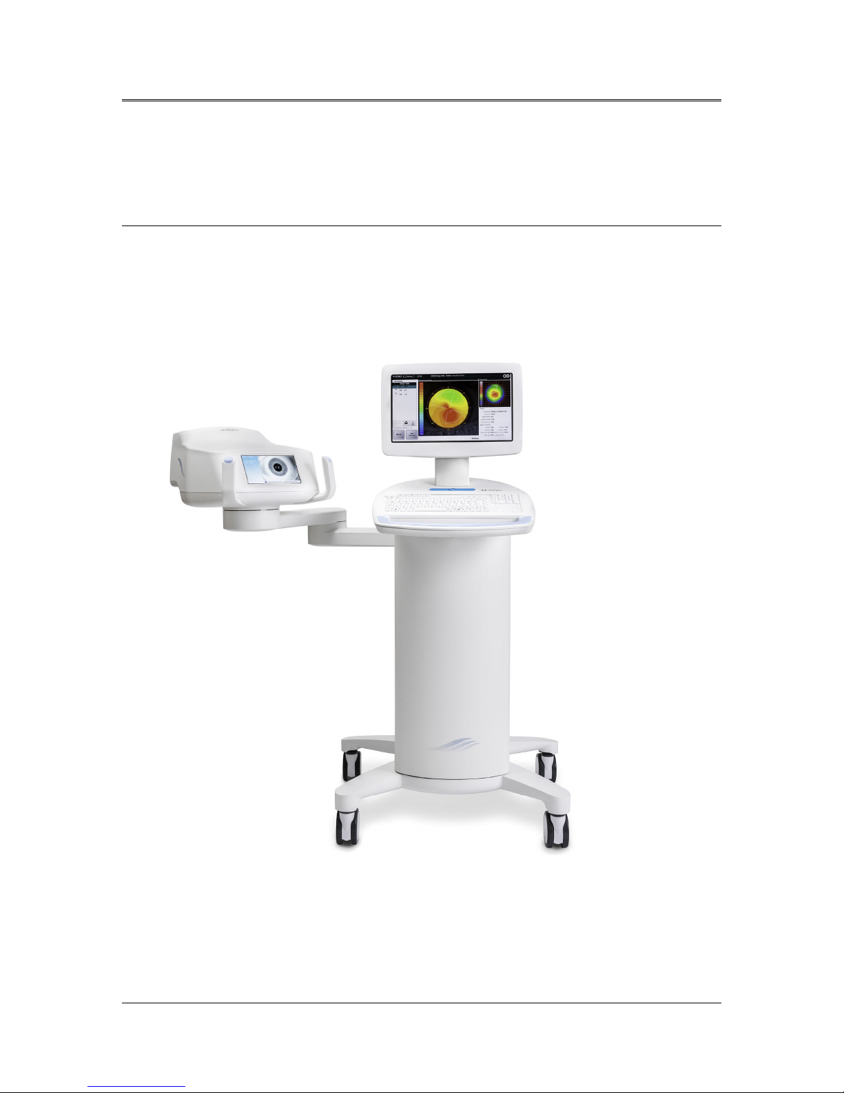
The Mosaic System is an electronic medical device which delivers
ultraviolet light (365 nm wavelength) in a programmable pattern onto the
cornea after a solution of ophthalmic riboflavin has been applied.
Irradiating the riboflavin creates singlet oxygen, which forms
intermolecular bonds in corneal collagen, stiffening the cornea through
cross-linking. UV flux and irradiation time (i.e., fluence) at the cornea are
controlled by an onboard computer system.
The Mosaic is a portable system with an articulating arm to allow
movement of the System for alignment of the UV beam to the patient’s
cornea. The Optics Head houses the UV irradiation mechanism. The height
of the Optics Head can be adjusted through a lift in the body of the
System. The LED is preset by the manufacturer to emit UV radiation at a
wavelength of 365 nm at an intensity of 10 mW/cm2 to 100 mW/cm2
(±10%).
The treatment parameters (Riboflavin Induction Period, Total UV Energy,
UV Treatment Patterns, UV Power and UV Pulse Cycle Times) are selected
through the user interface touchscreen.
The Mosaic System is used in conjunction with an ophthalmic riboflavin
solution and a Treatment Activation card.
NOTE: The depictions of the Mosaic System and user interface
screenshots included in this manual are for demonstration purposes
only. Actual product may vary due to product enhancements.
ML-00023

AVEDRO | 9 of 62
2.1.1 Major Components
The major components of the Mosaic System include the following:
• Articulating arm with optics head with UV source and heads up
display
• Mosaic console with user interface
• Mosaic Accelerated Crosslinking Treatment Kit (disposable
supplied separately)
• USB flash drive port
• System Part Number: 110-03092
Figure 2-1. Overview Illustration of Mosaic System
ML-00023
Mosaic Operator’s Manual Rev F | Page 10
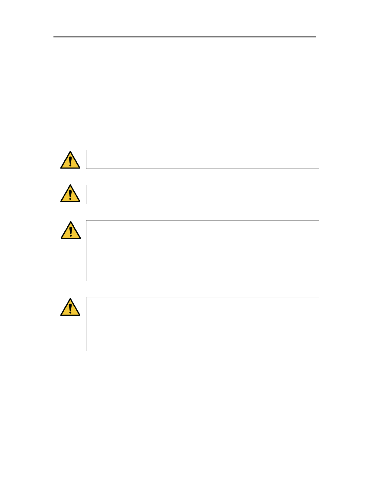
B C D E F G H
A
A Main Console with USB flash drive
port and Treatment Card slot
B System Keyboard
C System Body with lift system
D Articulating Arm
E Heads Up Display
F Optical Head
G Stand by Switch
H Wheels
Figure 2-2. System Overview with Callouts
2.1.2 Disposables
The following disposables (supplied separately) are required for
performing treatments with the Mosaic System:
• Riboflavin ophthalmic solutions
• Treatment Activation card
• Boost Goggles (optional)
ML-00023
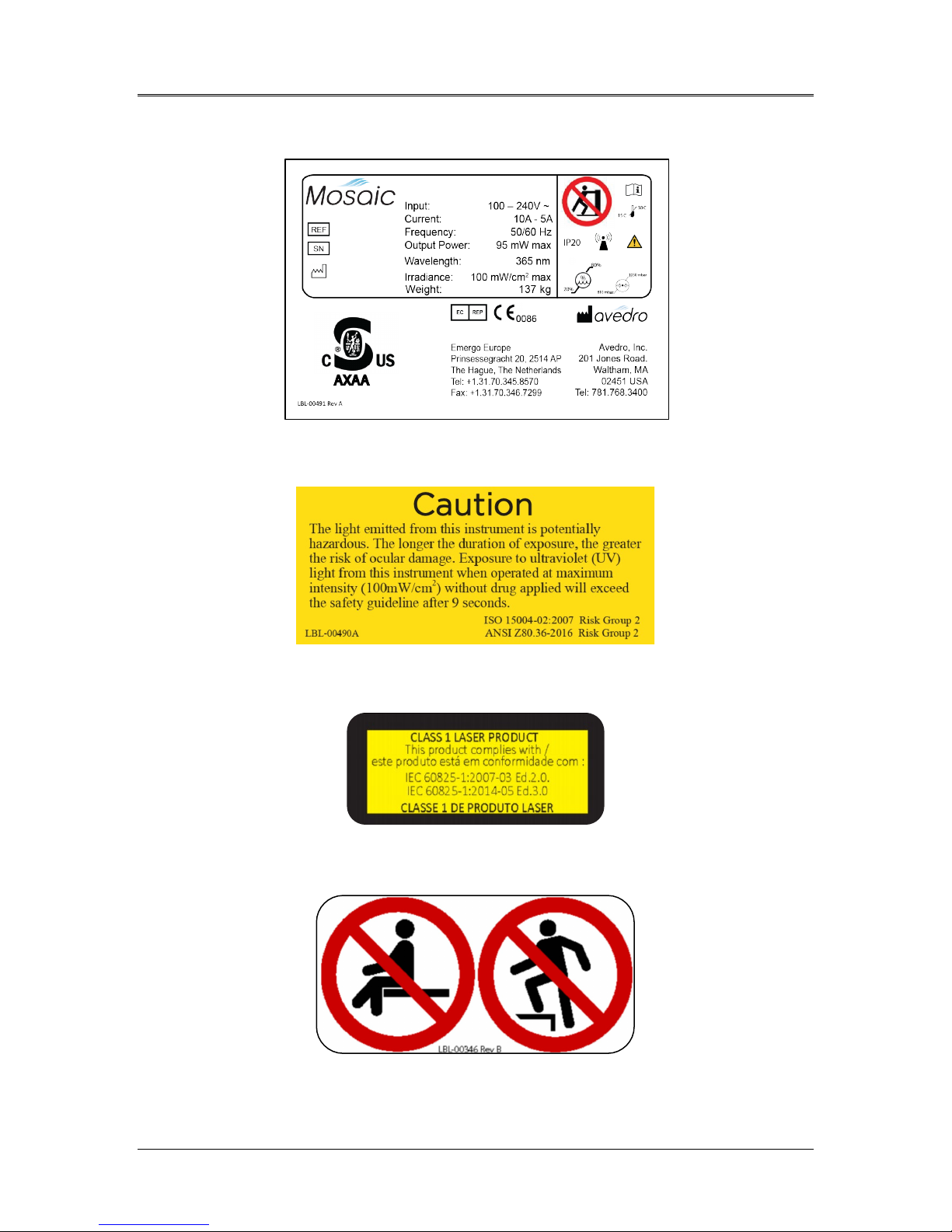
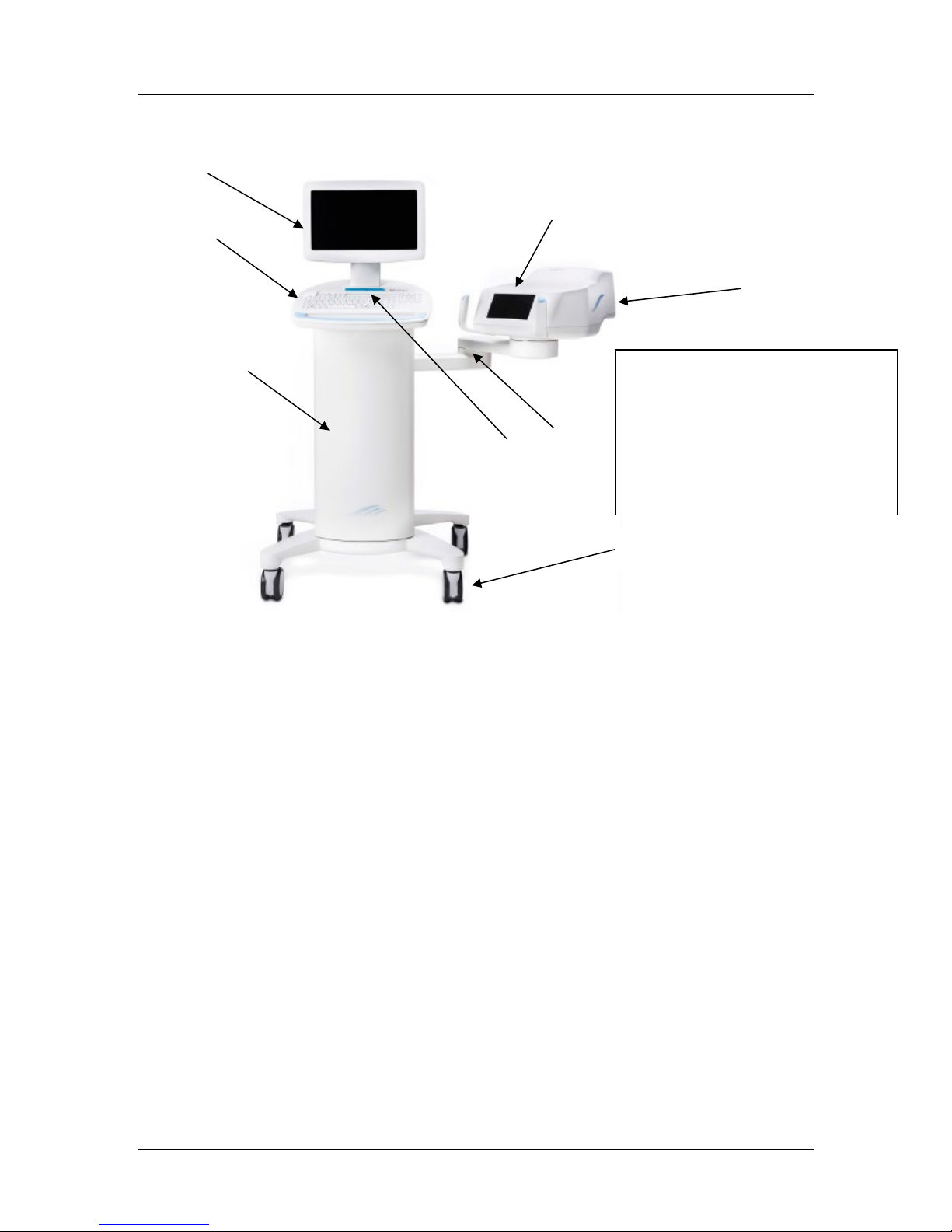
2.1.3 Mosaic System Labels
Figure 2-3. Mosaic Label
AVEDRO | 11 of 62
Figure 2-4. UV Safety Label
Figure 2-5. Laser Classification Label
Figure 2-6. Do Not Sit/Step On Label
ML-00023

Mosaic Operator’s Manual Rev F | Page 12
Function
Mode
Manual
Section
2.1.4 Frequently Used Functions
The table below identifies the System functions that are most
frequently used and where to find these functions described in this
Manual.
Turn System On Press Stand By switch under the keyboard in
4.3
the front of the Mosaic console
Treatment
Design
Scan Treatment
Activation Card
Begin UV
Treatment
Select “Design OD”/ “Design OS”. This initiates
a new treatment design.
Insert Treatment Activation card into slot on
the left side of main console
Select “Begin UV Treatment”. This becomes
available at the end of the patient preparation
5.2
5.3
5.10
step.
Pause Select “Pause” to interrupt treatment at any
5.10
time.
Go on Stand By Select “Power Off” on main console display 5.13
ML-00023
AVEDRO | 13 of 62
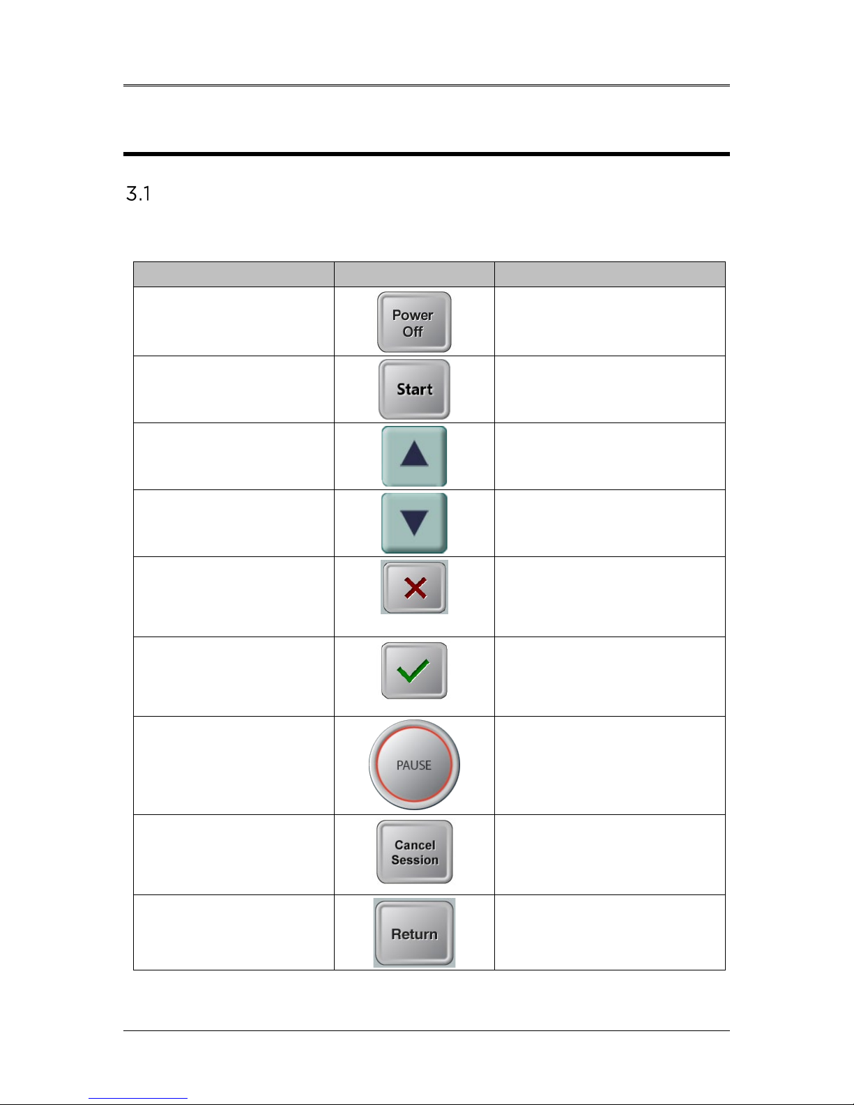
Touchpad Key
Icon
Description/Function
3 System Operation
Touchpad/Keyboard Use
The table below identifies and describes important touchpad keys and
icons unique to Mosaic System operation.
Power Off button
(Initial screen)
Start button (initial
screen)
UP arrow
(various Clinical
Protocol screens)
DOWN arrow
(various Clinical
Protocol screens)
X button
(various Device Settings
screens)
Checkmark button
(various Clinical
Protocol screens and
Device Settings screen)
Turns OFF electric power to
the console and goes on
Stand By Mode.
Directs the System from the
Startup Screen to Patient
Central.
Increases the value of the
current field.
Decreases the value of the
current field.
Cancels all the entries on a
particular screen and
returns to the previous
screen.
Directs the System to
accept the current screen
entries and to proceed to
the next step.
Pause button
(Treatment screen)
Cancel Session button
(various Clinical
Protocol screens)
Return button
(various Device Settings
screen)
ML-00023
Halts the delivery of UV
light until the physician
decides to realign the eye,
resume, or cancel the
treatment session.
Cancels a treatment session
for a particular patient. A
prompt is then displayed to
confirm your decision.
Returns to the Device
Settings menu.

Mosaic Operator’s Manual Rev F | Page 14
CAUTION: Only qualified and experienced personnel shall
operate the Mosaic System.
UV Energy (Dose)
• The UV Energy (Dose) is the product of the UV Power
(Intensity) and the UV Irradiation Time. The UV Energy, UV
Power and pulsing times are adjustable and the calculated total
treatment time is displayed.
• The System tracks UV Energy, UV Power, UV Irradiation Time
and Total Treatment Time during the treatment.
• Treatment Parameters:
- Induction Period: 1 second – 30 minutes
- UV Energy: 0 – 15 J/cm2
- UV Power: 10 – 100 mW/cm2 (± 10%)
• Please reference Riboflavin Instructions for Use (IFU) for
formulation information.
ML-00023
4 System Set Up
Important Steps before Turning on the System
• The user is responsible for assuring that the Mosaic System is
functioning properly, is within normal operating ranges for
temperature and humidity, and is in good-working condition
before starting a treatment.
• To ensure the System is functioning properly, consider the
following mandatory points:
- Inspect the device, accessories, and connecting cables
for visible damage.
Carefully inspect the power cord for any possible
damage prior to powering up the System.
- Take into consideration all local regulations for use of
portable electro-optical medical devices to minimize any
risk of electromagnetic interferences.
AVEDRO | 15 of 62
Preparing the System
• Position the Mosaic System adjacent to the treatment table or
chair. Lock the casters to secure the device’s position.
• Ensure that the power plug is readily accessible to the user and can
be easily unplugged by grasping the power cord plug and pulling
on it.
Powering Up
• Turn ON the stand-by switch under the keyboard in the front of
the Mosaic console. This switch turns on all the System
components and loads the Mosaic software.
ML-00023
Mosaic Operator’s Manual Rev F | Page 16
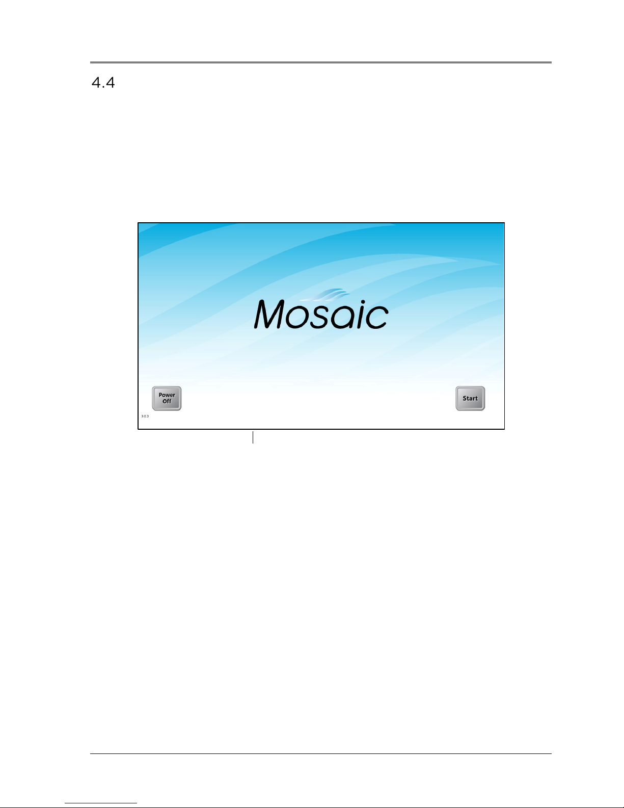
Startup Screen
• Once the single stand by switch above the keyboard is turned on,
the Mosaic System begins a power-up sequence, loading the
operating system and all configuration and reference files.
• The Mosaic software launches itself and the startup screen in
Figure 4-1 is displayed.
• To begin patient treatment, press Start.
Figure 4-1. Startup Screen
NOTE: If there is a Start-up Error, please note any error messages and
contact your distributor or Customer Service immediately.
ML-00023
AVEDRO | 17 of 62
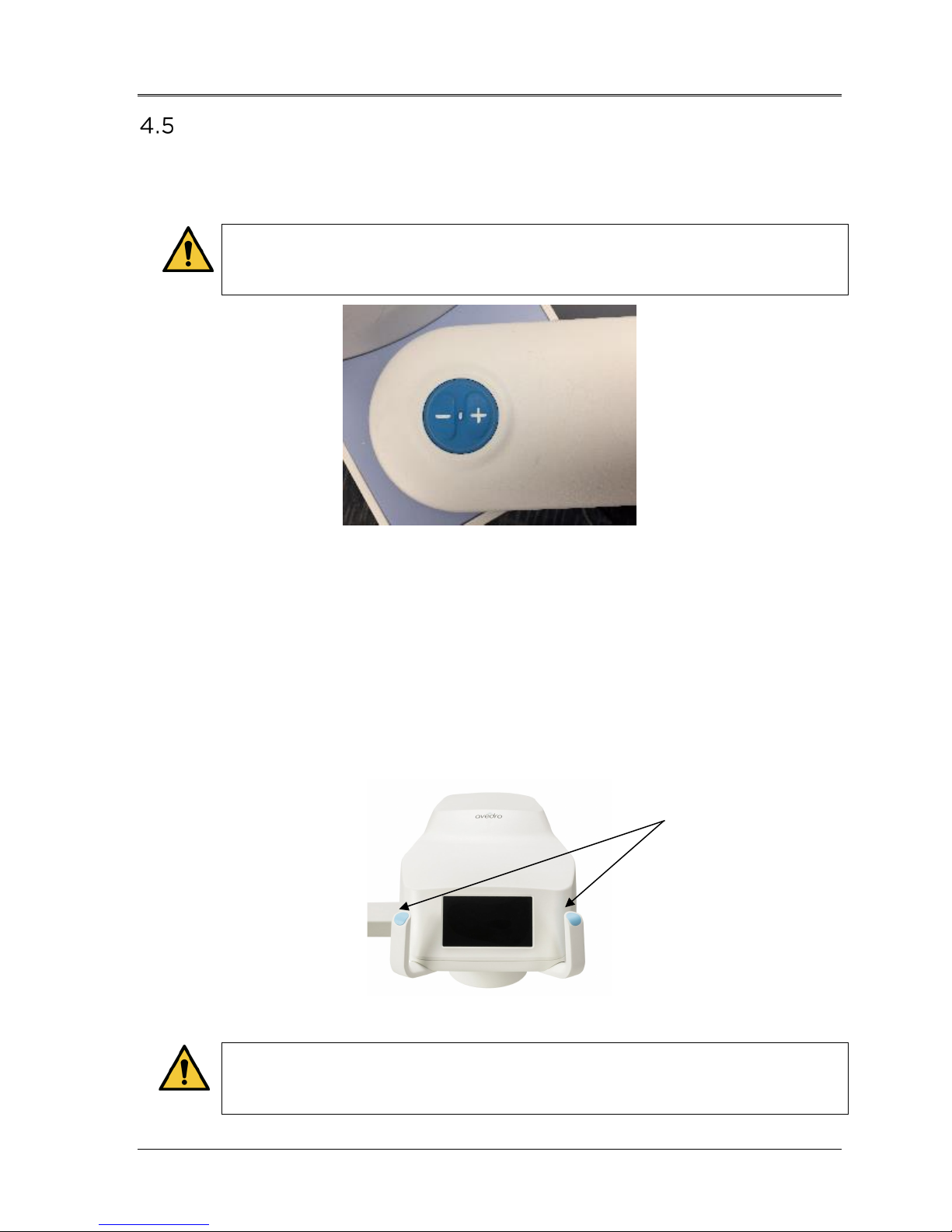
Setting Optics Head Height
• Continuously press the up /down (+ / -) button, shown below in
Figure 4-2, to raise or lower the optics head to the approximate
desired height above the treatment table or chair.
The lift is disabled during treatment. If the lift keeps moving
when the buttons are released, press the Stand By button and
contact your distributor or Customer Service immediately.
Figure 4-2. Lift Buttons
• The small LED between the up (+) and down (-) buttons will flash
when the lift reaches its maximum or minimum height.
• The small LED will also flash very rapidly if the proximity sensor is
triggered (see Section 3.5)
• Steer the optics head and align to desired position by continuously
pressing on either brake button (left or right) to disengage the
brakes of the articulating arm. See Figure 4-3 below. Once the
brake buttons are let go, the head locks into place.
Brakes
Brake release is disabled during treatment. In case of
emergency, the optics head can be steered away from patient
by grabbing the handles and moving the head away.
ML-00023
Figure 4-3. Optics Head
Mosaic Operator’s Manual Rev F | Page 18
Proximity Warning
• Moving the lift of the optical head too far down may trigger a
proximity sensor. This is a safety feature for the optical head not to
get too close to the patient’s head.
• If the proximity sensor is triggered, the lift will stop responding and
a warning will flash on the screen as shown below in Figure 4-4.
Figure 4-4. Proximity Warning: Move lift up
• Move the lift up to clear the proximity warning or ensure that no
object is obstructing the optical head underneath the UV window.
ML-00023
AVEDRO | 19 of 62
5 Treatment Procedure
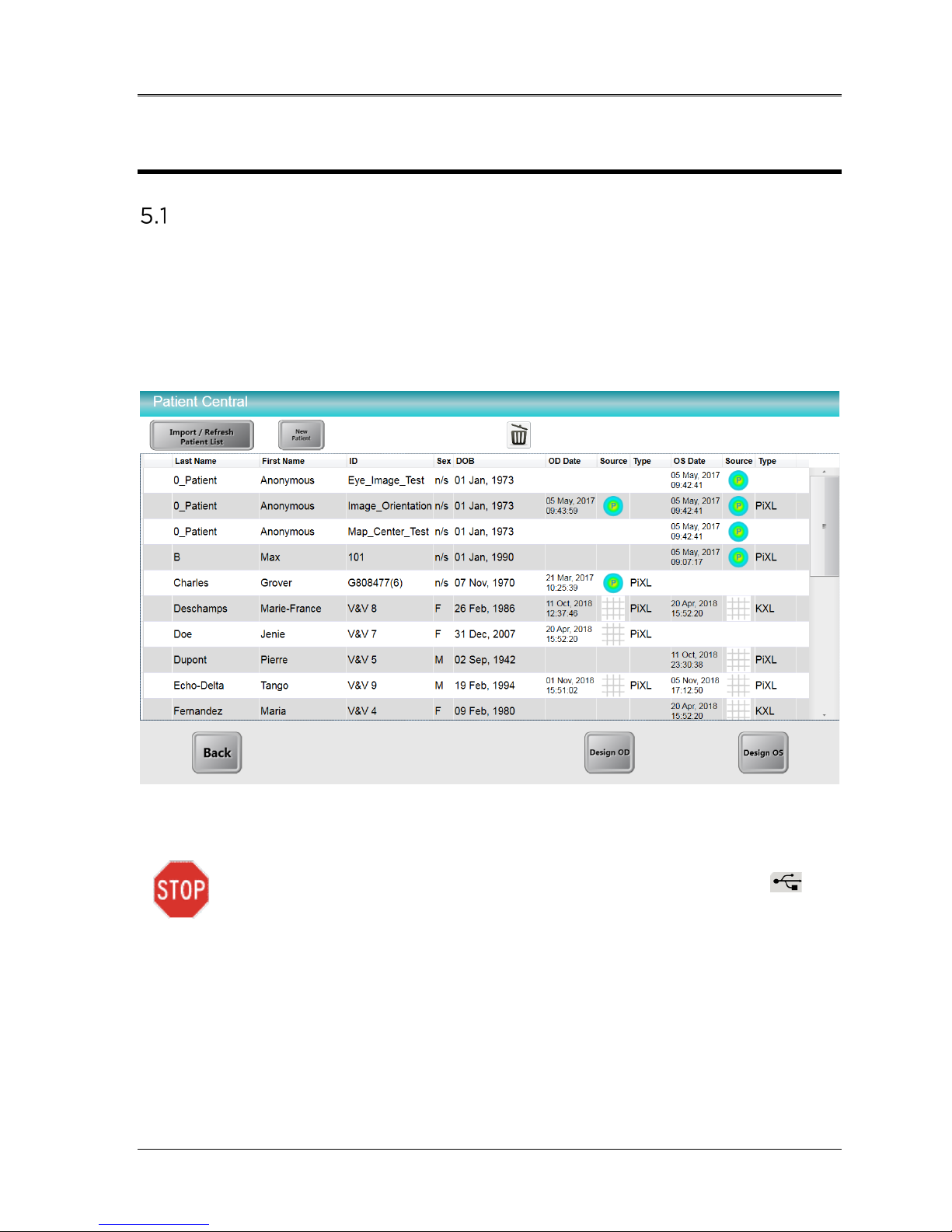
Patient Central
Patient Central is the main page where patient information can be imported
or new patient files can be created. No information is stored on the System
but is instead saved on the USB flash drive. Patient topographies can be
imported via Patient Central from the USB flash drive for guided treatment
patterns.
Figure 5-1. Import/Enter Patient Data Screen
A USB flash drive should be inserted in the USB slot ( ) to
proceed to a treatment plan.
5.1.1 Entering a New Patient
• Enter a new patient’s data by clicking on “New Patient” and filling
in the fields with the patient’s information.
- Note: Patient’s “First Name” and “Last Name” and Patient
“ID” are required fields. “Sex” and “D.O.B” will remain as
default if not edited.
ML-00023

Mosaic Operator’s Manual Rev F | Page 20
5.1.2 Importing Patient Topographies
Patient topographies exported onto a USB flash drive may be used with
the Mosaic System.
• Insert the USB flash drive into the Mosaic USB port.
• Click on “Import/Refresh Patient List” to refresh the page and list
all patients on the USB drive.
• Patient data imported from a commercial topographer can be
distinguished under the “Source” column.
Designing a Patient Treatment
• Starting from Patient Central, select the patient to be treated.
• Select “Design OD” or “Design OS” to create right or left eye
treatments respectively.
• Perform pupil center verification if applicable (only for patients
with topography imports).
5.2.1 Verifying Pupil Location
When patient topographies are imported and prior to creating treatment
maps, users will be prompted to verify the location of the pupil center as
shown in Figure 5-2. This is to ensure an accurate treatment location is
used for treatment.
ML-00023
Figure 5-2. Verifying Pupil Location

AVEDRO | 21 of 62
1 2 3 4 5
6
7
8
12
11
10
9
• If the location is confirmed, the user can proceed to the Treatment
Designer depicted in Section 5.3.
- The user must confirm the pupil location for each patient
record.
- If the pupil location needs to be reconfirmed, the user
can manually access the Settings Menu (see Section
5.2.7) and select the “eye” icon to reconfirm.
• If the location is not confirmed, the user will be prompted to create
a new patient record for the patient with a grid-base that can be
utilized for treatment map creation.
- The patient name will be the same, but a new patient ID
will be automatically generated.
5.2.2 Overview of the Treatment Designer
The various areas of the Treatment Designer are depicted in Figure 5-3.
1 Patient Information
2 Treatment/Shape Selections
3 Edit Treatment Options
4 Irradiance Power Selections
5 Done Button (to Patient Central)
6 Save & Confirm Button
Figure 5-3. Treatment Designer Layout
ML-00023
7 Main Design Map
8 Design Settings
9 X/Y Coordinate Tracking
10 Indices
11 Secondary Design Map
12 Right/Left Eye

Mosaic Operator’s Manual Rev F | Page 22
5.2.3 Treatment Type Options
Select “Add Shape” to select the type of treatment per clinical
requirements.
• KXL treatments are limited to one 9 mm circle.
• PiXL treatments can have up to five shapes that can be
juxtaposed or overlaid together.
5.2.4 Designing a KXL Treatment
NOTE: Requires KXL Treatment Activation Card
• Open the “Add Shapes” menu and select the “KXL” tab.
• Select the KXL 9 mm circle to add it to the treatment design.
• The circle can then be centered on the limbus, pupil or vertex
(if available) as shown in Figure 5-5. If no selection is made, the
circle automatically centers around the vertex (for topography
imports) or centers around the grid (for no topography
imports).
• Adjust the energy dosage as shown in Figure 5-5. Treatment
energy and irradiance limits are controlled by the KXL
Treatment Activation Card.
NOTE: Eye Tracking is available during a KXL Treatment on the
Mosaic.
ML-00023
Figure 5-4. Create KXL Treatment Design

AVEDRO | 23 of 62
Adjust
Energy
Center
Shape
Figure 5-5. Adjust Energy for KXL Treatment
5.2.5 Designing a PiXL or CuRV Treatment
NOTE: Requires PiXL Treatment Activation Card
• Open the “Add Shape” menu and select the “PiXL” tab.
• Select a PiXL treatment shape from the drop-down list as
depicted in Figure 5-6:
- Circular shapes of user-defined diameter
- 7 mm, 9 mm, and 11 mm circles are pre-set
- Ellipses of user-defined diameter and axis
- Single arcuate sector of user-defined size, thickness
and angle
- Symmetrical double arcuate sectors of user-defined
size, thickness and angle
- Annular surface with user-defined diameters
- Any free-hand user-defined drawn surface
ML-00023

Mosaic Operator’s Manual Rev F | Page 24
1
2 3 4
Figure 5-6. Treatment Shape Selection
• As shown in Figure 5-7, select the up/down arrow (1) to adjust
the energy required for the specific treatment shape. Treatment
time automatically adjusts itself based on energy dose selected.
• Use the X Position and Y Position (2) to adjust the location or
center around the Limbus, Pupil or Vertex (3) by selecting one
of the three buttons.
• Press green checkbox (4) to continue.
Figure 5-7. Selecting Energy Dose and Centering Shape
• Up to four additional shapes can be added (total of 5) and each
shape can be assigned with its own total energy selection.
• Press green checkbox to continue for each shape selected.
ML-00023

AVEDRO | 25 of 62
5.2.6 Multi-Shape Treatments
The order of shapes included in a multi-shape treatment design plays
an important role. The first shape has higher priority and the DMD
setting will be prioritized according to that higher priority shape. Figure
5-8 depicts an example of how changing the order of two shapes results
in different patient treatments.
• In the treatment summary on the left, the higher energy smaller
circle has higher priority; therefore, even when the 7 mm circle
treatment is complete after 6 minutes, the DMD keeps the
smaller circle ‘on’.
• In the second treatment summary on the right, the 7 mm circle
treatment has higher priority. Therefore, when the 6 minute
treatment is up, the DMD mirrors in that area shut off since the
treatment is up and the resultant treatment resembles the
smaller circle with an area cut off.
Figure 5-8. Resulting Treatment Pattern
5.2.7 Settings
The Settings menu, shown in Figure 5-9, allows the user to:
• Save and send a PDF report to the USB flash drive
• Change treatment map views
• Reconfirm pupil location (only for patients with topography
imports)
• Access the Help Section
ML-00023
Mosaic Operator’s Manual Rev F | Page 26
Figure 5-9. Settings Menu
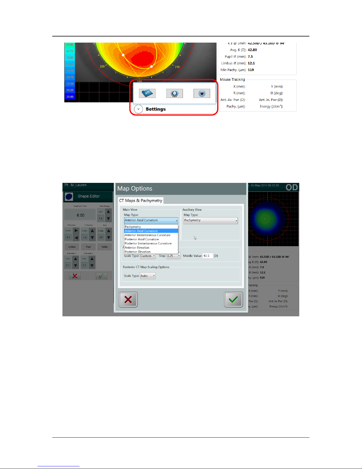
The Map Options settings menu, shown in Figure 5-10, allows the user
to choose the treatment map options (when applicable) to use on both
the Main Design Map (Main View) and the Secondary Map (Auxiliary
View).
Map options include but are not limited to:
• Pachymetry
• Anterior axial curvature
• Posterior axial curvature
• Front and back elevation maps
ML-00023
Figure 5-10. Settings for Map Options
AVEDRO | 27 of 62
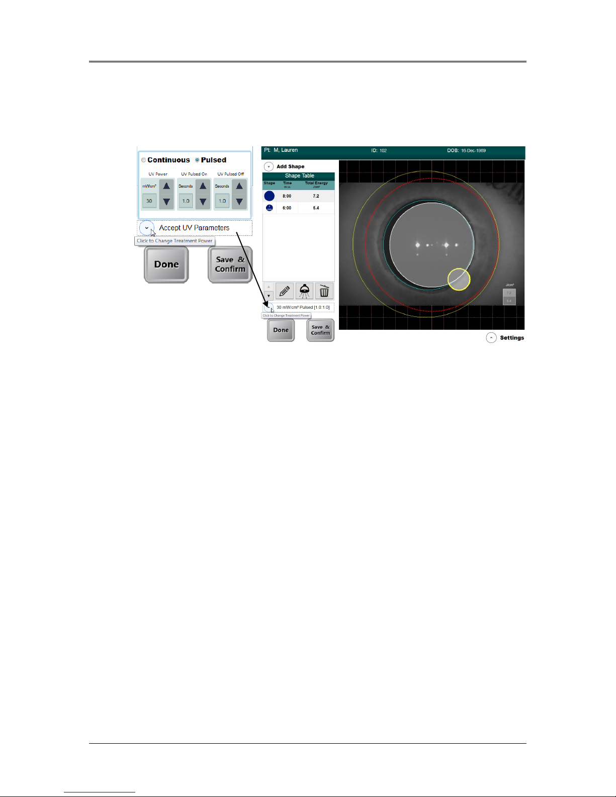
5.2.8 Adjusting Power (Irradiance) and UV Mode
• Power and UV mode (pulsed or continuous) settings can be
modified by clicking on the drop-down menu beside the power
(irradiance) value (see Figure 5-11).
Figure 5-11. Power and Pulse Settings
• When Pulsed UV is selected, the time on and off for Pulsed can
be adjusted using the up/down arrows. Pulsing times range
from 0.2 s – 4.0 s in 0.1 s increments.
• Once energy, power and all other parameters have been
entered, select “Start Treatment” to proceed with the treatment.
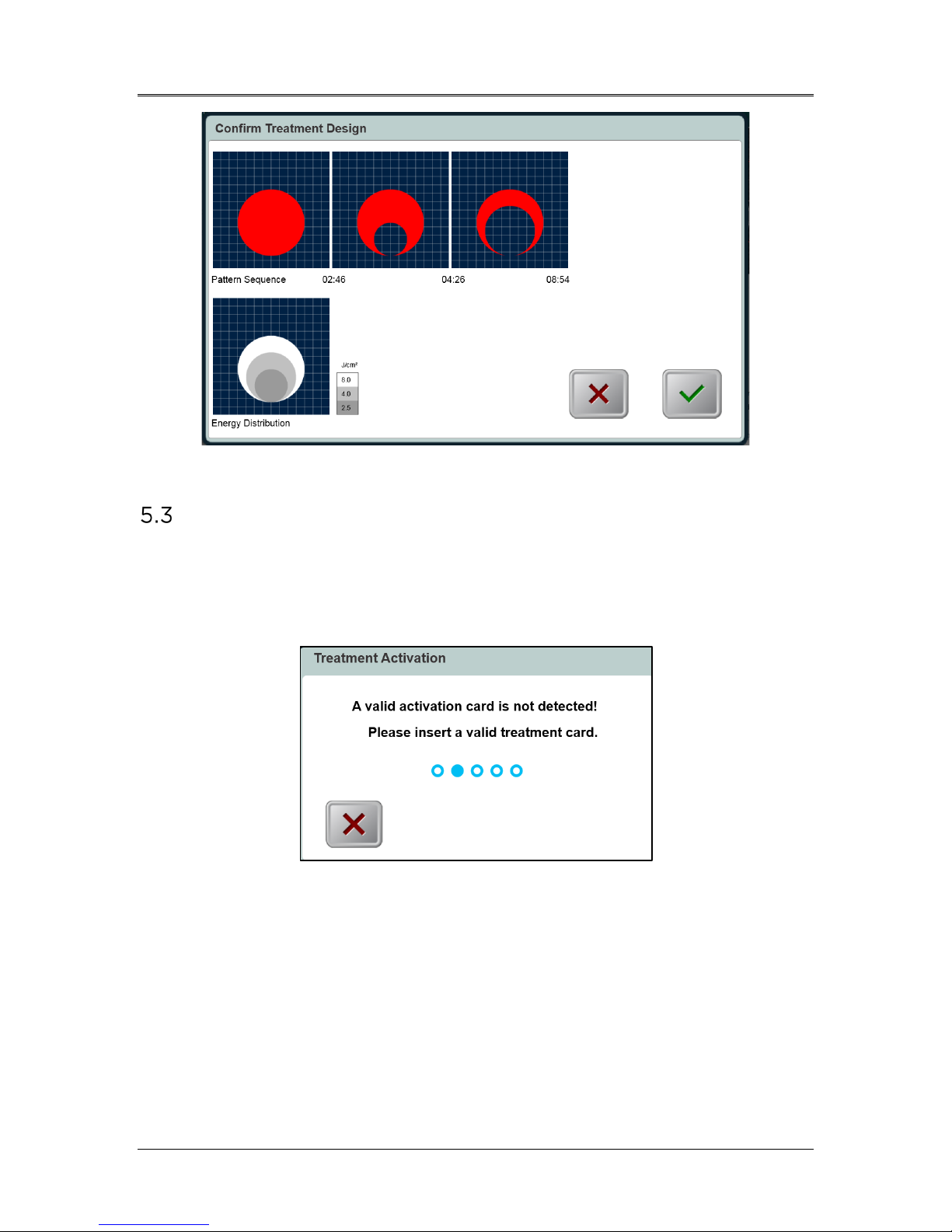
5.2.9 Confirm Treatment Design
• As the user enters the treatment parameters, the user can
confirm the treatment design by selecting the “Save & Confirm”
button. This can be done at any time during the treatment
design to help optimize treatment accuracy.
• As depicted in Figure 5-12, the Confirm Treatment Design
window shows a timeline of the various shapes that the UV
beam will make during the course of the treatment.
• For viewing multiple shapes, the user can move the slider left
and right.
• The lower square shows the energy dosage distribution for each
shape; darker shapes have lower energy while brighter shapes
have higher energy.
• Once the treatment design is confirmed, the user selects the
green checkmark to proceed with scanning the activation card.
ML-00023
Mosaic Operator’s Manual Rev F | Page 28
Figure 5-12. Confirm Treatment Design Window
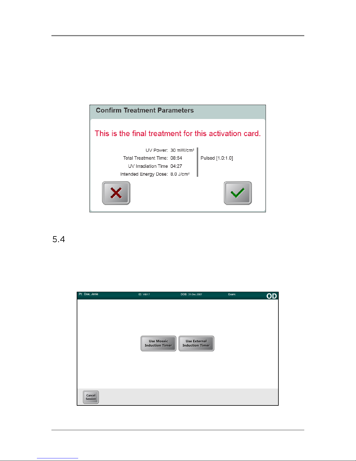
Treatment Activation Card
• After treatment design is confirmed, a treatment activation card
must be inserted to proceed with the patient treatment.
• If no card has yet been inserted, an error message will appear
as shown in Figure 5-13.
Figure 5-13. Activation Card Not Detected
• Insert the card into the slot on the left side of the main console.
• Selected treatment parameters must be within the allowable
values controlled by the treatment activation card (UV power,
energy, treatment time, etc.).
- For example, if the treatment design uses PiXL shapes,
a PiXL treatment activation card must be used.
- The user may edit the treatment design parameters to
meet the treatment activation card requirements.
ML-00023
AVEDRO | 29 of 62
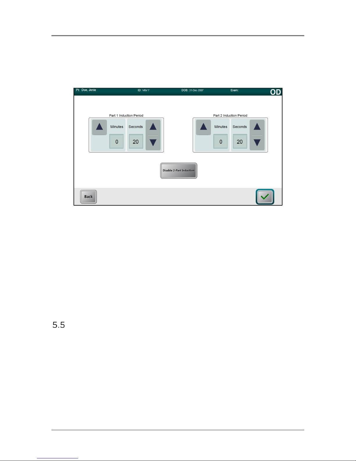
5.3.1 Multi-use Treatment Activation Cards
• When a multi-use activation card has been scanned, the display
will show the number of treatments remaining on the card.
• Prior to using the final treatment on a multi-use activation card,
a message, as shown in Figure 5-14, will appear to inform the
user that this is the final treatment.
Figure 5-14. Final Treatment
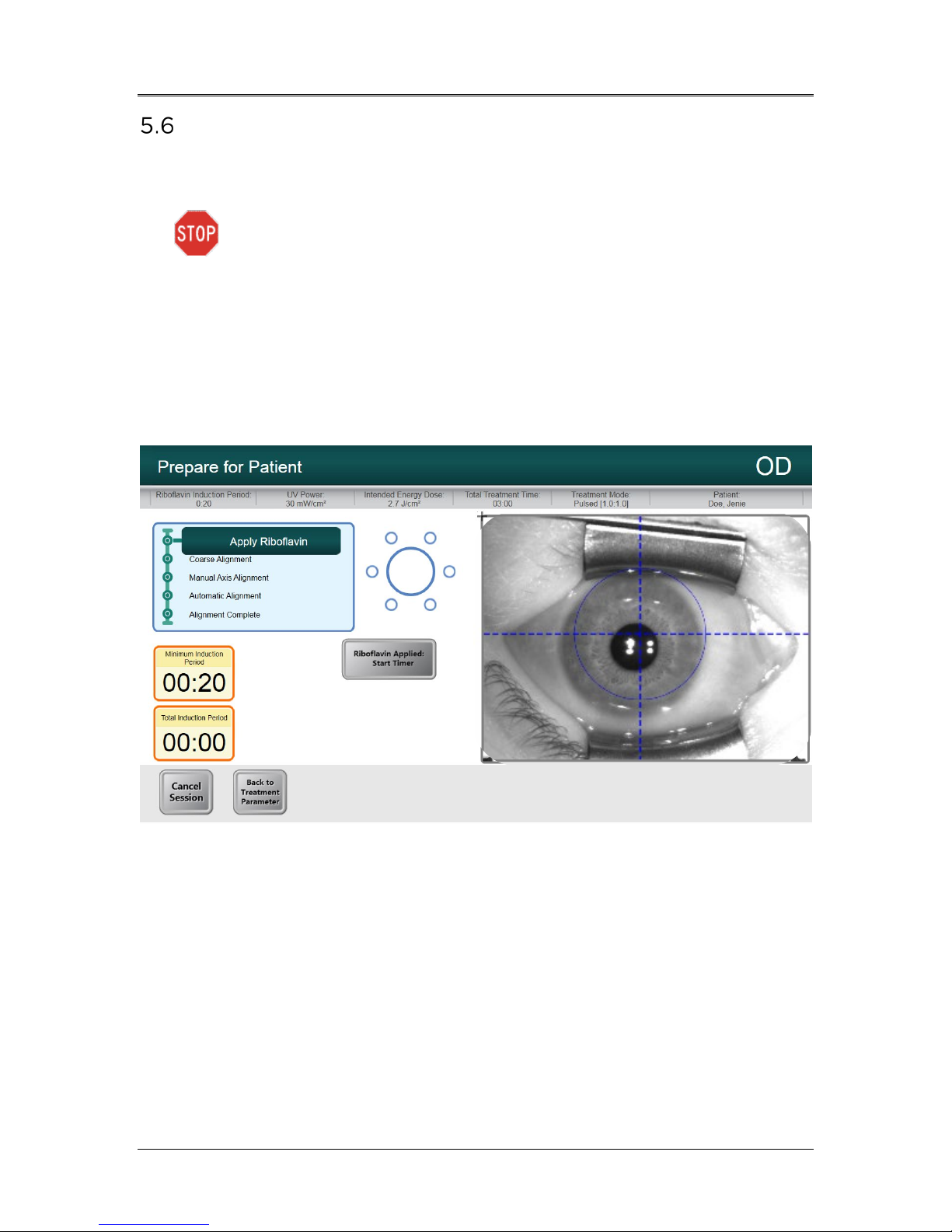
Set the Riboflavin Induction Time
To set the riboflavin induction time, the user has two options as shown in
Figure 5-15:
• Use the Mosaic Induction Timer
• Use the External Induction Timer
ML-00023
Figure 5-15. Induction Timer Options
Mosaic Operator’s Manual Rev F | Page 30
5.4.1 Mosaic Induction Timer
The Mosaic Induction Timer is a system-based timer that may be used
for either a single or a two-part induction process. See Figure 5-16.
Figure 5-16. Two-Part Induction Timer
• User specifies the desired riboflavin induction period (1 sec – 30
mins) by clicking on the up/down arrows.
• When finished entering parameters, select the green checkmark
button.
5.4.2 External Induction Timer
When the user selects the Use External Induction Timer button, it is
assumed that the user has an external timer and will by-pass both the
setting and the use of the Mosaic Induction Timer.
Prepare the Patient
• Ensure that the patient is lying flat or reclined on a patient table
or chair. His or her head should rest on a head rest.
• Adjust the table or chair and head rest so that the patient can
rest comfortably for the duration of the treatment without head
movement.
• Optional - When needed, mark the visual axis on the cornea
using a corneal Gentian Violet marker.
• Apply a lid speculum and optional drapes using standard clinical
technique.
ML-00023
AVEDRO | 31 of 62
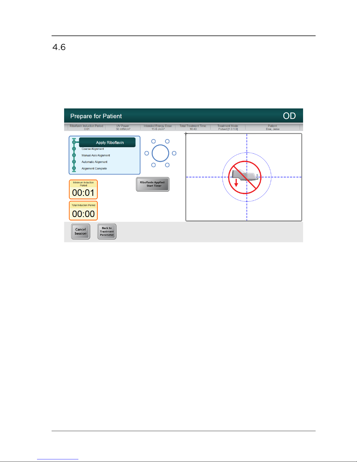
Apply Riboflavin
• Apply Riboflavin to the area of treatment in accordance with
the Riboflavin Instructions for Use (IFU).
CAUTION: Riboflavin is not a part of the Mosaic System
described in this manual. For details, please refer to the
Riboflavin Instructions for Use.
• Once the Riboflavin is applied to the eye, start timing the
induction.
If using the Mosaic Induction Timer: Select “Riboflavin
-
Applied: Start Timer,” as shown in Figure 5-17.
If using an External Induction Timer: Start external
-
timer and monitor induction time.
Figure 5-17. Apply Riboflavin & Start Timer Screen
ML-00023
Mosaic Operator’s Manual Rev F | Page 32
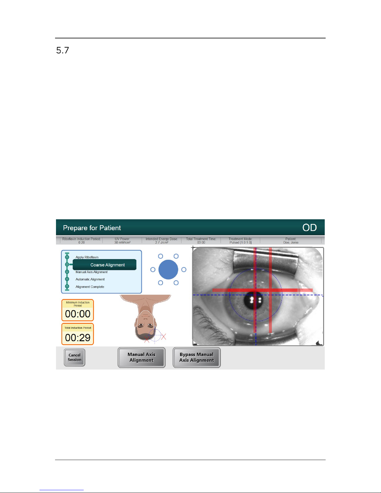
Coarse Alignment of Laser Crosshairs
The goal of the Coarse Alignment process is center the red crosshairs and
the blue circle over the treatment eye pupil, as shown in Figure 5-18. The
blue circle refers to the center of the DMD and the pupil should be aligned
to this center for optimal pupil tracking during treatment.
• Press the buttons on the handles of the articulating arm to
disengage the brakes.
• Steer the optics head over the patient’s head and treatment eye.
• Align the optics head such that the laser crosshairs are closely
aligned/overlapped on each other.
- The height of the optics head may require adjustment
by using the lift system described in Section 4.5 to
align the laser crosshairs.
• Align the crosshairs on the Heads Up Display to the center of
the treatment eye pupil.
• Release the buttons to engage the brakes once closely aligned.
Figure 5-18. Coarse Alignment with Lasers
ML-00023
AVEDRO | 33 of 62
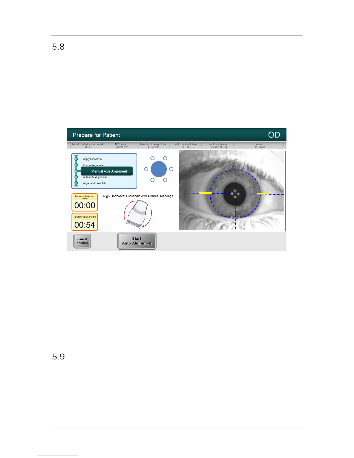
Manual Axis Alignment Mode
NOTE: Manual Axis Alignment Mode should only be selected for
patients who have had their corneal axis marked along the horizontal
meridian with a Corneal Gentian Violet marker. If the corneal axis has
not been previously marked and if no axis registration is desired, user
should select “Bypass Manual Axis Alignment.”
• Select “Manual Axis Alignment” to illuminate the cornea
rendering the axis markers on the cornea clearly visible, as
shown in Figure 5-19.
Figure 5-19. Manual Axis Alignment Mode
• Press the buttons on the handles of the articulating arm to
disengage the brakes.
• Rotate the optics head such that the visual axis markers are
aligned with the horizontal blue line on the Heads Up Display.
• Alignment should continue aiming to position the center of the
pupil to the center of the crosshairs and the blue circle.
• Once aligned, release the brakes.
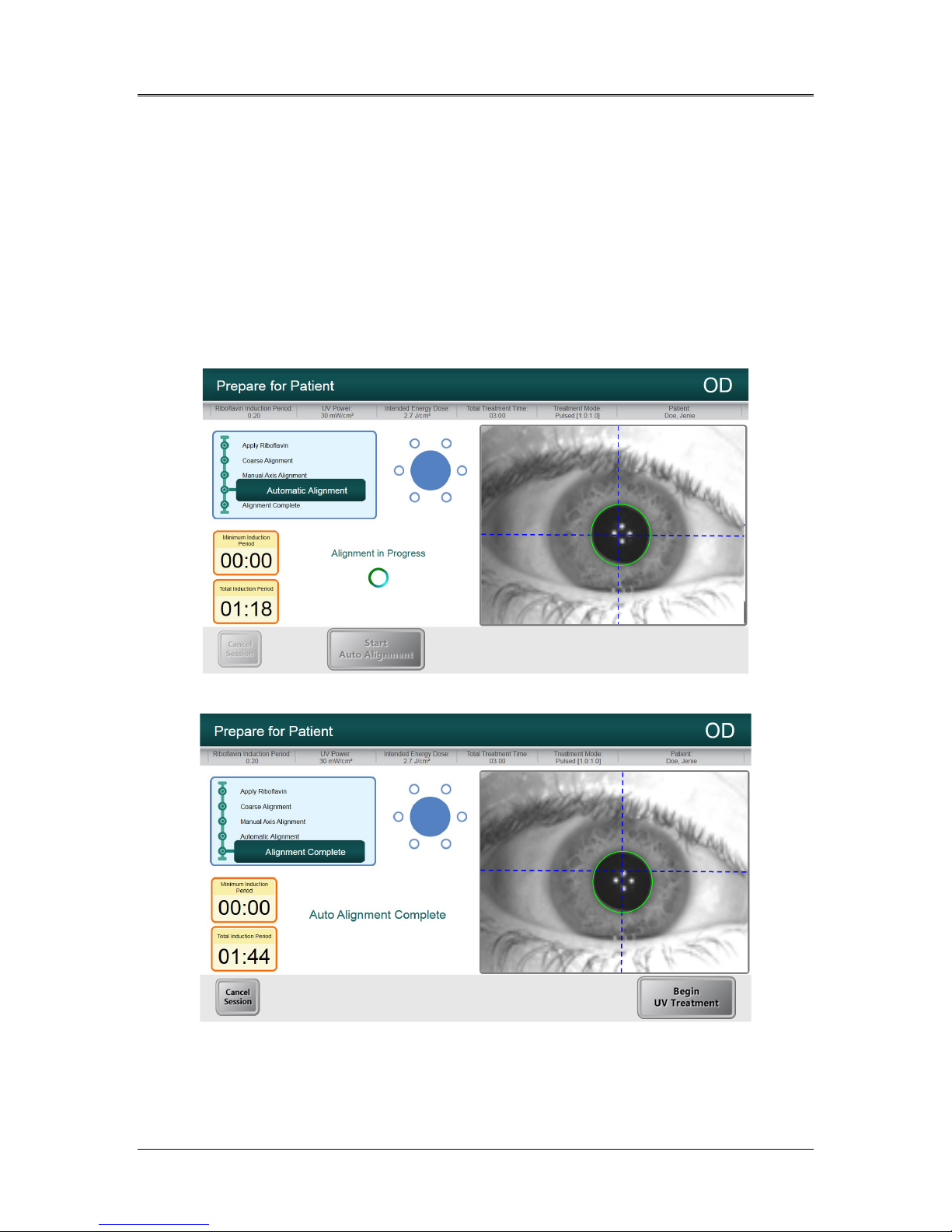
Auto Alignment
Select “Start Auto Alignment.” Auto alignment is a three-step process as
follows:
• Auto-aligns in X-Y axes for pupil tracking;
• Auto-aligns in the Z axis for best focus;
ML-00023
Mosaic Operator’s Manual Rev F | Page 34
• Compensates for cyclo-torsion
- Performs iris registration from the imported
topographer (when available)
- For cases where a topography is not available, the
Manual Axis Alignment allows the user to manually
adjust for cyclo-torsion.
Figure 5-20 displays the onscreen auto alignment process and Figure 5-21
shows the onscreen user alert when auto alignment successfully
completes.
Figure 5-20. Alignment in Progress
Figure 5-21. Alignment Complete
• When both auto alignment and riboflavin induction are
complete, the “Begin UV Treatment” button appears.
ML-00023
AVEDRO | 35 of 62
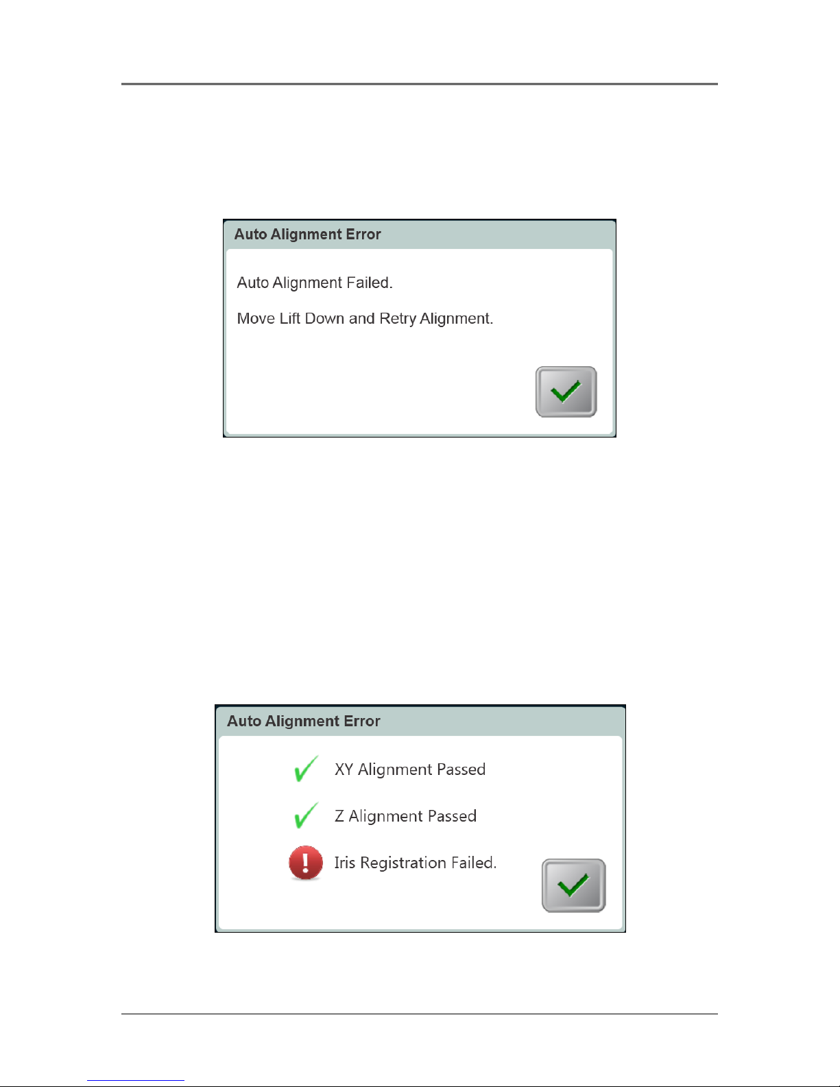
5.9.1 Unsuccessful Auto Alignment
• Auto alignment may fail during any of the three processes for
various reasons including the head being out of range, or poor
image contrast. If so, an error message will appear as shown in
Figure 5-22 to notify the user.
Figure 5-22. Z-Alignment Error
• The error message may instruct the user to move the lift up or
down before retrying alignment.
- The user should use the lift to move the optics head
up or down until the image of the eye looks more
focused. This will facilitate the auto focus algorithm
when the user restarts the auto alignment process.
• In the case of iris registration failure, as shown in Figure 5-23,
the user is notified of the failure and has the option to restart
the auto alignment or forego auto alignment and proceed with
manual alignment, as shown in Figure 5-24.
ML-00023
Figure 5-23. Iris Registration Failure

Mosaic Operator’s Manual Rev F | Page 36
Figure 5-24. Restart Auto Alignment or Manual Alignment Option
• Selecting manual alignment provides use of motor controls to
manually align in X-Y and Z direction.
WARNING: In case of manual alignment for asymmetrical
treatment shapes, the user should manually perform
rotational alignment in order to accurately apply the
treatment.
• Within Manual Alignment Mode, the user can toggle between
Manual Axis Alignment for aligning the axis to corneal markings
on the patient’s cornea, and Alignment Lasers for manual
alignment in X-Y and Z direction. See Figure 5-25.
Figure 5-25. Toggling between Manual Axis Alignment & Alignment Lasers
ML-00023

AVEDRO | 37 of 62
Begin UV Treatment
The user is notified by an audible sound once induction and alignment is
complete.
• Select “Begin UV Treatment” to start UV irradiation.
WARNING: Start treatment only after the photosensitizer is
applied.
Figure 5-26. Begin UV Treatment
• Once UV is on, the software will track the eye and the UV
pattern will follow the eye, irradiating the same specific region
of the cornea.
• An onscreen treatment tracker shows Treatment Time
Remaining, Total Energy Delivered and Total Induction Period.
See Figure 5-27.
ML-00023
Figure 5-27. Treatment in Progress

Mosaic Operator’s Manual Rev F | Page 38
• UV treatment can be paused or interrupted at any time by
selecting the “Pause button”. This turns the UV irradiation off.
Figure 5-28. Pausing UV Treatment
• Prior to resuming UV treatment, ensure that the alignment is
correct. The user can choose to re-align or proceed without realigning and select “Resume” to start the UV irradiation again.
Treatment Complete
• At the completion of a treatment, a summary of treatment
parameters will be displayed, and the screen will show
“Treatment Completed”, as shown in Figure 5-29.
Figure 5-29. Treatment Complete Screen
• To exit treatment and/or start a new treatment, select “Start
New Treatment.”
• If treatments are complete, Power OFF the System using the
“Power Off” button on the Main Screen and unplug the System.
ML-00023

AVEDRO | 39 of 62
• Carefully remove the device from the patient area.
• Remove speculum and provide post-op treatment according to
appropriate clinical protocol.
Treatment Incomplete
• If for some reason, the treatment is cancelled or stopped before
it is complete, the patient record in Patient Central will be
annotated with a red exclamation mark (!)
• In Patient Central, click on the red exclamation mark to show
the actual treatment performed vs. the intended treatment, as
shown in Figure 5-30.
• User can retreat patient to complete the remaining dosage. If
this treatment is performed again to complete the treatment
dosage, the red exclamation mark annotation will be removed.
Figure 5-30. Treatment Incomplete Annotation
Power Down the System
• Press the “Back” button in Patient Central
• Press the “Power Off” button then press “Power Off” again, as
shown in Figure 5-31 to go on Stand By Mode.
• Unplug the System to power down.
ML-00023

Mosaic Operator’s Manual Rev F | Page 40
Figure 5-31. Power Down System
ML-00023

6 Device Settings
Using the Device Settings Menu
• To access the Device Settings Menu, press the “Back” button
from Patient Central to navigate to the main initiation screen.
• Press the Mosaic logo on the touchscreen to open the Device
Settings Menu as shown in Figure 6-1.
AVEDRO | 41 of 62
Figure 6-1. Device Settings Menu
6.1.1 Advanced Settings
Advanced Settings are only available to Avedro and Service personnel
with a Mosaic Advanced Settings access card. If selected, the user will
be prompted to scan an access card.
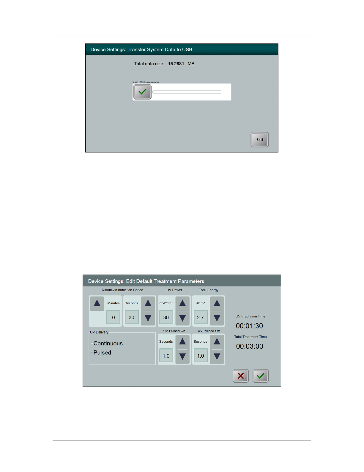
6.1.2 Transfer Data to USB
• Select “Transfer Data to USB” on the Device Settings Menu.
ML-00023
Mosaic Operator’s Manual Rev F | Page 42
Figure 6-2. Device Settings Transfer to USB
• Insert a USB device into the USB port.
• Press the checkbox to copy treatment data to the USB. The
System begins transferring the treatment data and shows a
progress bar of the transfer process.
• Once complete, select “Exit”. The System will return you to the
Device Settings menu.
6.1.3 Edit Default Treatment Parameters
• The user may elect to edit the default settings for the Induction
Period, UV Power, Total Energy, and UV Mode.
Figure 6-3. Edit Default Treatment Parameters (Continuous & Pulsed)
• When finished editing treatment parameters, select the green
checkmark.
ML-00023
AVEDRO | 43 of 62
6.1.4 Patient Prescreen Test
The patient prescreen test allows the user to prescreen a patient with
an intra-ocular lens (IOL) or a cataract to ensure that the IOL will not
interfere with the auto alignment and eye tracking system during a
future treatment.
Prescreening should be performed with a lid speculum in place and
room lighting configured as it would be during treatment.
NOTE: no UV light is delivered during the prescreen. Only diagnostic
NIR and pulsed yellow light are used for this process.
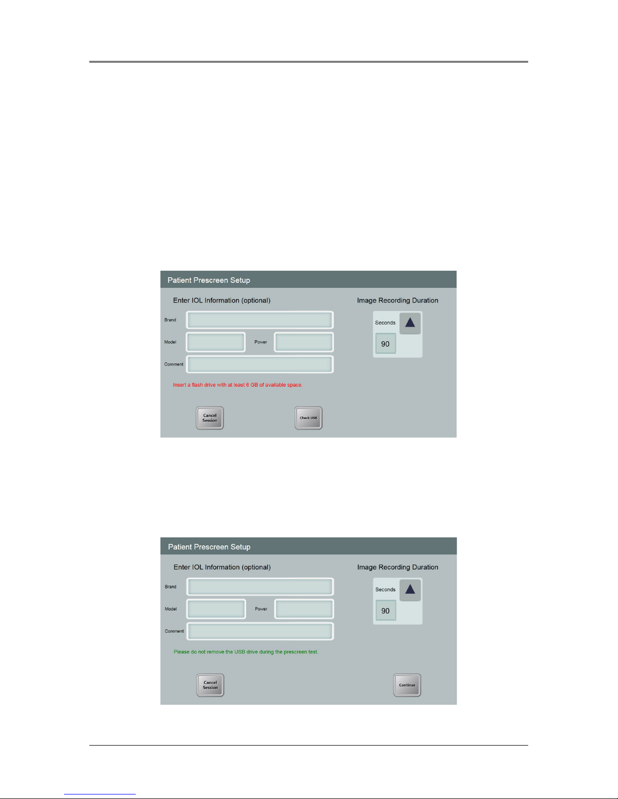
• Select Patient Prescreen Test.
• Insert a USB drive with at least 6 GB of available space.
Figure 6-4. Insert flash drive
• Optional - Enter information regarding the IOL brand, model
and power.
• Select the video Image Recording Duration (from 90 seconds
to 180 seconds, with default at 90 seconds).
Figure 6-5. Enter IOL Information
ML-00023
Mosaic Operator’s Manual Rev F | Page 44
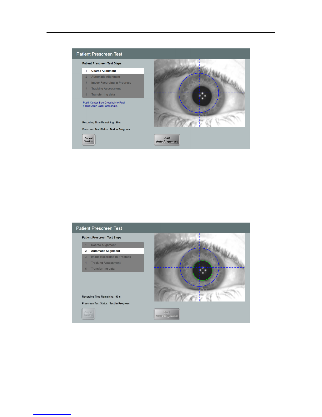
• Select “Continue to” proceed with the screening.
Figure 6-6. Alignment Step
• In the Patient Prescreen Test, the user is prompted to perform
the coarse alignment procedure (see Section 5.7).
• Once coarse alignment is complete, select “Start Auto
Alignment” to start the auto alignment.
• The device starts auto alignment as well as image recording.
• Each step of the Patient Prescreen Test is tracked onscreen.
Figure 6-7. Screening Step Process
• Throughout the recording period, the user should watch the
process onscreen to confirm that the green circle is correctly
tracking the pupil during the auto alignment and image
recording steps.
ML-00023
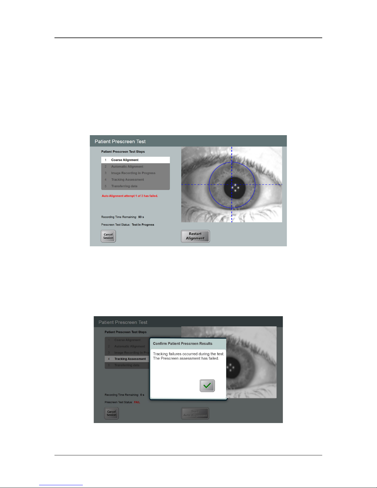
• Failure Modes
- If auto alignment fails, the user has two more attempts
to repeat the auto alignment.
- Confirm that the patient is properly positioned prior to
repeating auto alignment.
- If all three auto alignment attempts fail, the prescreen
has failed and the user should not proceed with the
treatment.
AVEDRO | 45 of 62
Figure 6-8. First Attempt Fail
• If auto alignment succeeds but eye tracking failures are
detected by the System during the image recording period, as
shown in Figure 6-9, the prescreen has failed and the user
should not proceed with the treatment.
Figure 6-9. Failed Prescreen Assessment Due to Eye Tracking Errors
ML-00023
Mosaic Operator’s Manual Rev F | Page 46
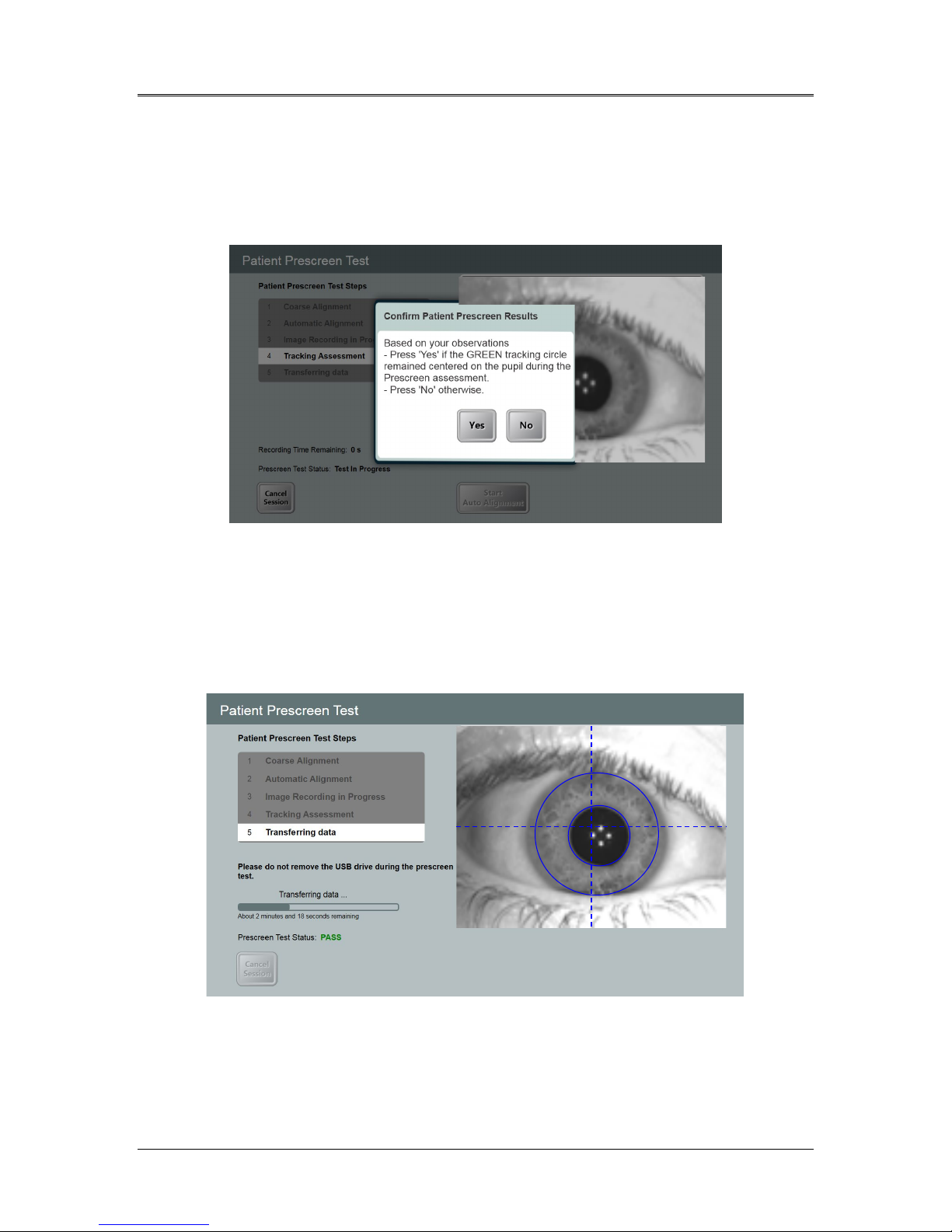
• Pass Mode
- Auto alignment passes and no eye tracking failures
are detected by the System
- User is asked to confirm that the green circle correctly
tracked the pupil throughout the recording period.
Figure 6-10. Confirm Patient Prescreen Results
- Select “Yes” to confirm.
- An onscreen “Pass” message as shown in Figure 6-11
will indicate that the test is complete and data will be
transferred to the USB drive. Do not remove the USB
drive during this step.
• A patient who passes the prescreen test is eligible for treatment.
ML-00023
Figure 6-11. Prescreen Test Pass

AVEDRO | 47 of 62
6.1.5 Demo Mode
NOTE: Not for use in treating patients
Demo mode allows users to train on use of the Mosaic System without
requiring treatment cards and without using UV light.
• Select “Demo Mode”
• Select “Start” to use the System in Demo Mode
ML-00023

AVEDRO | 48 of 64
7 Maintenance / Service
In this manual, “maintenance” refers to those non-technical procedures an
everyday operator performs to keep the System working properly.
“Service,” by contrast, refers to tasks that are intended to be performed
only by a qualified service representative.
Installation Policy
• For each new Mosaic System customer, a trained person may
provide a full initial installation and start-up of the System.
Following initial installation and once the System is operating
properly, the trained person may also provide basic training to
a designated operator.
• Consequently, this manual does not include any specific
instructions relating to installation or set-up of the System. Per
your service agreement, any further hardware adjustment, other
than what is specified for normal operation, should be
performed by, or with the guidance of, an Avedro-authorized
distributor.
Customer Maintenance
• In general, there is no customer maintenance required for the
Mosaic System.
• All technical service will be performed by a qualified service
representative while under service contract.
• If you have trouble with your System, refer to the
troubleshooting section below or call your local Avedro
Representative.
Warranty Information
• A Warranty is supplied separately with the purchasing
information.
Per Patient Disposables
• Per Patient Disposables can be ordered from Avedro or your
Avedro-authorized distributor.
• Use only Avedro products or Avedro-approved products
with your Mosaic System.
ML-00023
AVEDRO | 49 of 62
• Avedro shall not be liable for damage to or malfunction of the
System, which it deems, was caused by the use of unauthorized
materials.
Trouble Shooting
• The Mosaic System checks its status at start-up automatically.
• If the status is incorrect, the software prevents the operator
from initiating treatments when the System is in the normal
operating state.
Directions for Disinfection
• Do NOT sterilize any components of the Mosaic System.
• External cleaning and disinfection ONLY is recommended. For
disinfection purposes, use only isopropyl alcohol spray or
preparations. Use small amounts of liquid and soft fiber-free
wipes.
Cleaning the System
• Use a soft damp cloth to clean the System.
• The exterior of the Mosaic System can be cleaned using a lint-
free cloth dampened with soapy water.
- A 70% isopropyl alcohol or 10% chlorine bleach
solution can also be used, if necessary.
• Do NOT submerge the System in liquid or pour liquid onto the
System.
CAUTION: Remove the power supply cord from the main
outlet and turn off the power switch prior to any cleaning
procedure.
CAUTION: Aggressive cleaning agents, especially those
containing abrasives or aggressive solvents can damage
component surfaces.
• The glass window of the beam aperture must not under any
circumstances be in contact with any of the aforementioned
substances.
• While cleaning the surfaces of the device, ensure that cleaning
fluids do not seep inside the device, as this leakage can damage
the device.
ML-00023
Mosaic Operator’s Manual Rev F | Page 50
Cleaning the Aperture
• Check the beam aperture routinely prior to treatment.
• Use special camera lens wipes or compressed air to remove
dust and particles from the glass surface of the aperture.
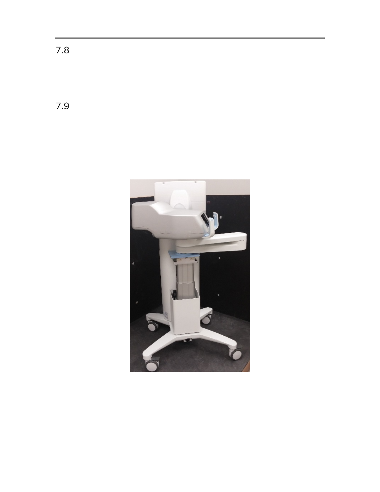
Moving the System
• The Mosaic is designed as a movable system within an office
environment.
• When moving the System, ensure that the articulating arm and
the head are retracted close to the monitor as shown in the
image below for safe motion from one place to another.
Figure 7-1. Moving Position of the Mosaic System
• Transport or shipment of the Mosaic System should be
performed only by Avedro trained and authorized personnel.
Contact your local Avedro representative.
ML-00023
AVEDRO | 51 of 62
Storing the System
• Follow all the storage temperature and humidity range
specifications as listed in Section 10, Specifications.
• Allow System to re-equilibrate to normal operating
temperatures and humidity ranges prior to re-starting System.
• Close all panels on the System to prevent dust and moisture
from entering; this is mandatory.
• Turn OFF all the components and the main power supply as
well. Disconnect the power cord physically from its electrical
outlet.
• Cover the touchscreen LCD display and keyboard with its
original cover or packaging to prevent any damage.
• Do not disassemble any part of the System as this could cause
misalignment or damage.
Software
• Contact your local Avedro service representative for any
suspected software corruption or failure to work correctly.
• Software updates will only be performed by Avedro-trained
service representatives.
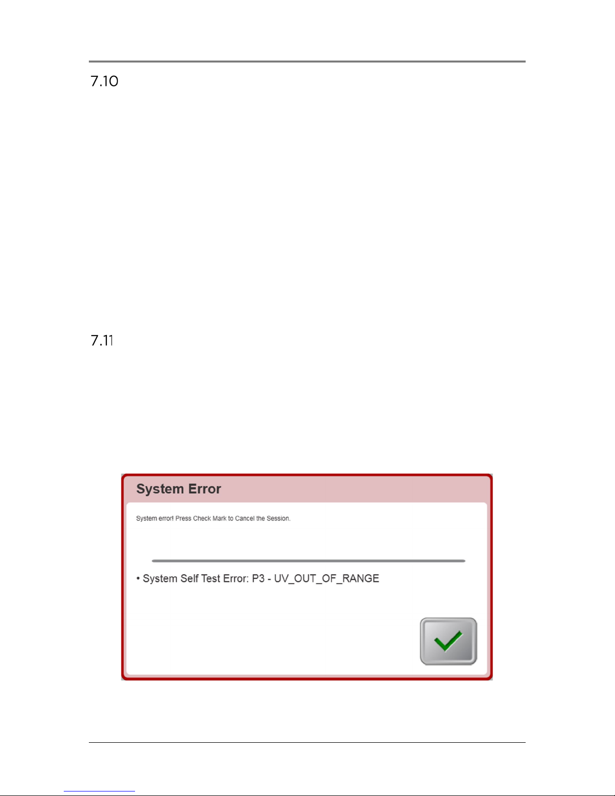
• Contact your local Avedro service representative if an error
message appears as displayed below in Figure 7-1. Record and
share the error code with your Avedro service representative.
Figure 7-2. Example Error Message Box
ML-00023

Mosaic Operator’s Manual Rev F | Page 52
Identifying Risks Associated with Disposing of Waste
Products
• When disposing of waste products, residues, Mosaic System,
and accessories, follow all applicable local regulations or
contact an Avedro-authorized distributor.
Performing a Visual Check
• Check all components of the device routinely for damage or
malfunction prior to each treatment.
• Do not use a damaged or malfunctioning device. Use of such
devices may harm the user and/or patient.
ML-00023

AVEDRO | 53 of 62
8 Equipment Classification
According to IEC60601-1:2005+A1:2012 Medical Device Electrical
Standard
• Protection against electrical shock
o Class 1 (external electrical power source)
• Degree of protection against electric shock
o Not classified, equipment not provided with applied part
• Degree of protection against ingress of water
o Common Devices IP20 (No protection against ingress of
water)
• Method of sterilization or disinfection
o Disinfect-able device
• Degree of protection for use in the presence of a flammable
such as aesthetic mixture
o No protection
• Use conditions
o Continuous service
According to FCC Part 15, IEC55011 and IEC60601-1-2
• Class B
According to Annex II.3 of Directive 93/42/EEC
• Class IIa
According to IEC 60825-1 Ed. 2.0 2007-03 Safety of laser products
• Alignment lasers are Class 1 Laser Product
According to IEC 60825-1 Ed. 3.0 2014-05 Safety of laser products
• Alignment lasers are Class 1 Laser Product
Conforms to the following standards:
• IEC 60601-1:2005+A1:2012
• ANSI/AAMI ES 60601-1
• CSA C22.2 No 60601-1:14
ML-00023

Mosaic Operator’s Manual Rev F | Page 54
System has been qualified for use with the following cables and
listed may result in
electromagnetic environment specified
System should assure that it is used in
ystem uses RF energy only for its internal
function. Therefore, its RF emissions are very low and are
not likely to cause any interference in nearby electronic
hments
and those directly
voltage power supply
network that supplies buildings used for domestic
EMC Requirements
The Mosaic System requires special precautions regarding
electromagnetic compatibility (EMC). Installation and use
should be carried out according to the EMC information
provided in this manual. Portable and mobile RF
communications equipment may affect the Mosaic System.
The Mosaic
accessories. Use of cables, and accessories other than those
increased emissions or decreased immunity of the Mosaic System.
Cables Accessories
None USB 2.0 compliant flash drive
Guidance and manufacturer’s declaration - electromagnetic emissions
The Mosaic System is intended for use in the
below. The customer or the user of the Mosaic
such an environment.
Emissions test Compliance Electromagnetic environment — guidance
RF emissions
CISPR 11
RF emissions
CISPR 11
Harmonic emissions
IEC 61000-3-2
Group 1 The Mosaic S
equipment.
Class B The Mosaic System is suitable for use in all establis
including domestic establishments
connected to the public low-
Class A
purposes.
Voltage fluctuations/
flicker emissions
IEC 61000-3-3
Complies
ML-00023

AVEDRO | 55 of 62
ystem should assure that it is used in such an
Input /Output Lines
sec
sec
The Mosaic System should not be used adjacent to, or
stacked on top of, other equipment. If the Mosaic System
must be used adjacent to or stacked on top of other
equipment, verify that the Mosaic System operates in an
acceptable manner in the configuration in which it will be
used.
Guidance and manufacturer’s declaration — electromagnetic immunity
The Mosaic System is intended for use in the electromagnetic environment specified below.
The customer or the user of the Mosaic S
environment.
Immunity test IEC 60601 test level Compliance level Electromagnetic environment -
guidance
Electrostatic
discharge (ESD)
IEC 61000-4-2
Electrical fast
transient/burst
IEC 61000-4-4
Surge
IEC 61000-4-5
Voltage dips,
short
interruptions and
voltage variations
on power supply
input lines
IEC 61000-4-11
±8 kV contact
±15 kV air
±2 kV for power supply
lines
±1 kV for input/output
lines
±1 kV line(s) to line(s)
±2 kV line(s) to earth
0 % UT
(100 % dip in UT) for
0.5 cycle
0% UT
(100% dip in UT) for 1
cycles
70% UT
(30% dip in UT) for
25/30 cycles
0% UT
(100 % dip in UT) for 5
±8 kV contact
±15 kV air
±2 kV for power supply
lines
Not Applicable
±1 kV line(s) to line(s)
±2 kV line(s) to earth
0 % UT
(100 % dip in UT) for
0.5 cycle
0% UT
(100% dip in UT) for 1
cycles
70% UT
(30% dip in UT) for
25/30 cycles
0% UT
(100 % dip in UT) for 5
Floors should be wood, concrete or
ceramic tile. If floors are covered
with synthetic material, the relative
humidity should be at least 30%.
Mains power quality should be that
of a typical commercial or hospital
environment.
Mains power quality should be that
of a typical commercial or hospital
environment.
Mains power quality should be that
of a typical commercial or hospital
environment, If the user of the
Mosaic System requires continued
operation during power mains
interruptions, it is recommended
that the Mosaic System be powered
from an uninterruptible power
supply or a battery.
Power frequency
(50/60 Hz)
magnetic field
IEC 61000-4-8
NOTE UT is the a.c. mains voltage prior to application of the test level.
ML-00023
30 A/m 30 A/m
Power frequency magnetic fields
should be at levels characteristic of a
typical location in a typical
commercial or hospital environment.

Mosaic Operator’s Manual Rev F | Page 56
System is intended for use in the electromagnetic environment specified
used
NOTE 2 These guidelines may not apply in all situations. Electromagnetic propagation is affected by
absorption and reflection from structures, objects and people.
mobile radios, amateur radio, AM and FM radio broadcast and TV broadcast cannot be predicted theoretically
o fixed RF transmitters, an electromagnetic site
System is used
normal
orienting or
Guidance and manufacturer’s declaration — electromagnetic immunity
The Mosaic
below. The customer or the user of the Mosaic System should assure that it is
in such an environment.
Immunity test
Conducted RF
IEC61000-4-6
Radiated RF
IEC 61000-4-3
Proximity fields from
RF wireless
communications
equipment (IEC
61000-4-3:2006
A1:2007 A2:2010)
IEC 60601
test level
3 Vrms
150 kHz to 80
MHz
3 V/m
800 MHz to
2.7 GHz
15 specific
frequencies.
Immunity level
9-28V/m
Compliance
level
3 Vrms
3V/m
15 specific
frequencies.
Immunity level
9-28V/m
Electromagnetic environment —
guidance
Portable and mobile RF communications
equipment should be used no closer to any
part of the Mosaic System, including cables,
than the recommended separation distance
calculated from the equation applicable to
the frequency of the transmitter.
Recommended separation distance
= 1.2√ 80 MHz to 800 MHz
= 2.3√ 800 MHz to 2.7 GHz
where P is the maximum output power
rating of the transmitter in watts (W)
according to the transmitter manufacturer
and d is the recommended separation
distance in meters (m).
Field strengths from fixed RF transmitters,
as determined by an electromagnetic site
survey, a should be less than the
compliance level in each frequency range.b.
Interference may occur in the vicinity of
equipment marked with the following
symbol:
NOTE 1 At 80 MHz and 800 MHz, the higher frequency range applies.
a Field strengths from fixed transmitters, such as base stations for radio (cellular/cordless) telephones and land
with accuracy. To assess the electromagnetic environment due t
survey should be considered. If the measured field strength in the location in which the Mosaic
exceeds the applicable RF compliance level above, the Mosaic System should be observed to verify
operation. If abnormal performance is observed, additional measures may be necessary, such as rerelocating the Mosaic System.
b Over the frequency range 150 kHz to 80 MHz, field strengths should be less than 3 V/m.
ML-00023

AVEDRO | 57 of 62
aration distances between portable and mobile RF
which radiated RF disturbances are controlled. The customer or the user of
System can help prevent electromagnetic interference by
nd mobile RF
System as
recommended below, according to the maximum output power of the
For transmitters rated at a maximum output power not listed above, the
s (m) can be estimated using the
here P is the maximum
ransmitter in watts (W) according to the transmitter
Recommended sep
communications equipment and the Mosaic System
The Mosaic System is intended for use in an electromagnetic environment in
the Mosaic
maintaining a minimum distance between portable a
communications equipment (transmitters) and the Mosaic
communications equipment.
Rated
maximum
output power of
transmitter (W)
0.01 0.12 0.12 0.23
0.1 0.38 0.38 0.73
1 1.2 1.2 2.3
10 3.8 3.8 7.3
100 12 12 23
recommended separation distance (d) in meter
equation applicable to the frequency of the transmitter, w
output power rating of the t
manufacturer.
NOTE 1 At 80 MHz and 800 MHz, the separation distance for the higher frequency
range applies.
NOTE 2 These guidelines may not apply in all situations. Electromagnetic propagation
is affected by absorption and reflection from structures, objects and people.
Separation distance according to frequency of transmitter m
150 kHz to 80 MHz
= 1.2√
80 MHz to 800 MHz
= 1.2√
800 MHz to 2.7 GHz
= 2.3√
ML-00023
Mosaic Operator’s Manual Rev F | Page 58
The Mosaic System contains an RFID function which
transmits and receives at the 13.56 MHz frequency. This
functionality may be interfered with by other equipment,
even if that other equipment complies with CISPR emission
requirements.
The Mosaic System contains the following RF transmitters:
RFID Reader
• 13.56MHz Reader/Writer
• Integral Antenna: Maximum 4” Read Range
• Max output power is 200mW
• Meets: ISO18000-3, ISO15693
WiFi Adapter
Frequency Modulation 5 GHz (802.11a/n) 2.4 GHz (802.11b/g/n)
Frequency band 5.15 GHz - 5.85 GHz
(dependent on country)
Modulation BPSK, QPSK, 16 QAM, 64
QAM
Wireless Medium 5 GHz UNII: Orthogonal
Frequency Division
Multiplexing (OFDM)
Channels 4 to 12 (dependent on
country)
Max Output Power < 100mW <100mW
2.400 - 2.4835 GHz
(dependent on country)
CCK, DQPSK, DBPSK
2.4 GHz ISM: Orthogonal
Frequency Division
Multiplexing (OFDM)
Channel 1-11 (US only)
Channel 1-13 (Japan,
Europe)
ML-00023
anesthetics
9 Symbol Library
Text Symbol Symbol Illustration Definition
AVEDRO | 59 of 62
1. No AP symbol in
presence of flammable
2. AC symbol
3. “I” in a book
4. Ground symbol in
circle
5. Ingress Protection
Symbol
6. CE Mark
7. Manufacturer
IP20
Danger, Risk of Explosion.
Not for use
Alternating current
Attention: Consult
ACCOMPANYING
DOCUMENTS
Protected earth (ground)
Ingress Protection solids
under 12.5 mm and no
protection against water)
Conformity mark
Name and address of the
manufacturer
8. Date of Manufacture
9. ! in a yellow triangle
10. Net Weight (kgs)
Gross Weight (kgs)
11. Umbrella with
raindrops
ML-00023
Date manufactured
Caution specific warning in
operator’s manual
NW
GW
Net Weight
Gross Weight
Keep Dry: Store protected
from moisture (symbol is
with or without rain drops)
Mosaic Operator’s Manual Rev F | Page 60
Text Symbol Symbol Illustration Definition
12. Wine glass with crack
on it
13. Two up arrows
14. Percent sign on sea
level
15. Temperature limits
16. Reference Number
17. Serial Number
or
Contents are fragile, handle
with care
Keep arrows on carton
pointing up
Humidity limits
(percentages below
symbol are the acceptable
range for humidity)
Temperature shipment
limits
System reference number
System serial number
18. EC RP
19. Do not Push
20. Do not Sit On
21. Do not Step On
European Authorized
Representative
Do no push unless in the
right moving configuration
Do not Sit on Optical Head
Do not Step on Optical
Head
ML-00023
AVEDRO | 61 of 62
Text Symbol Symbol Illustration Definition
22. Atmospheric Pressure
limits
23. Stand By
24. Signal emitted
Operate within
atmospheric pressure limits
shown on System
System in Stand By Mode
RF transmitted through
device
ML-00023
Mosaic Operator’s Manual Rev F | Page 62
Specification
Description
Fuse: T 10H, 250V
365 nm
condensation).
deterioration.
10 Specifications
Electrical Line voltages 100 – 240 volts AC, ± 10%
Current 10A – 5A
Single Phase
50/60 Hz, ± 5%
Energy Delivery UV Radiation
10 – 100 mW/cm
External Interfaces USB 2.0
Physical Dimensions 103 x 81 x 152 cm3
(Length x Width x Height)
Weight NW 137 Kg
GW 217 Kg
Environmental Operating
Conditions
The System operates under the
following atmospheric conditions (no
2
Ambient temperature +15 to +30ºC
Relative humidity 20% to 80%, non-condensing
Atmospheric pressure 810 to 1050 mbar
Transport and Storage Conditions The System withstands the following
transport and storage conditions
without damage or performance
Ambient temperature -10 to +60 ºC
Relative humidity 10% to 80%, non-condensing
Atmospheric pressure 750 to 1060 mbar
ML-00023

This page intentionally left blank.
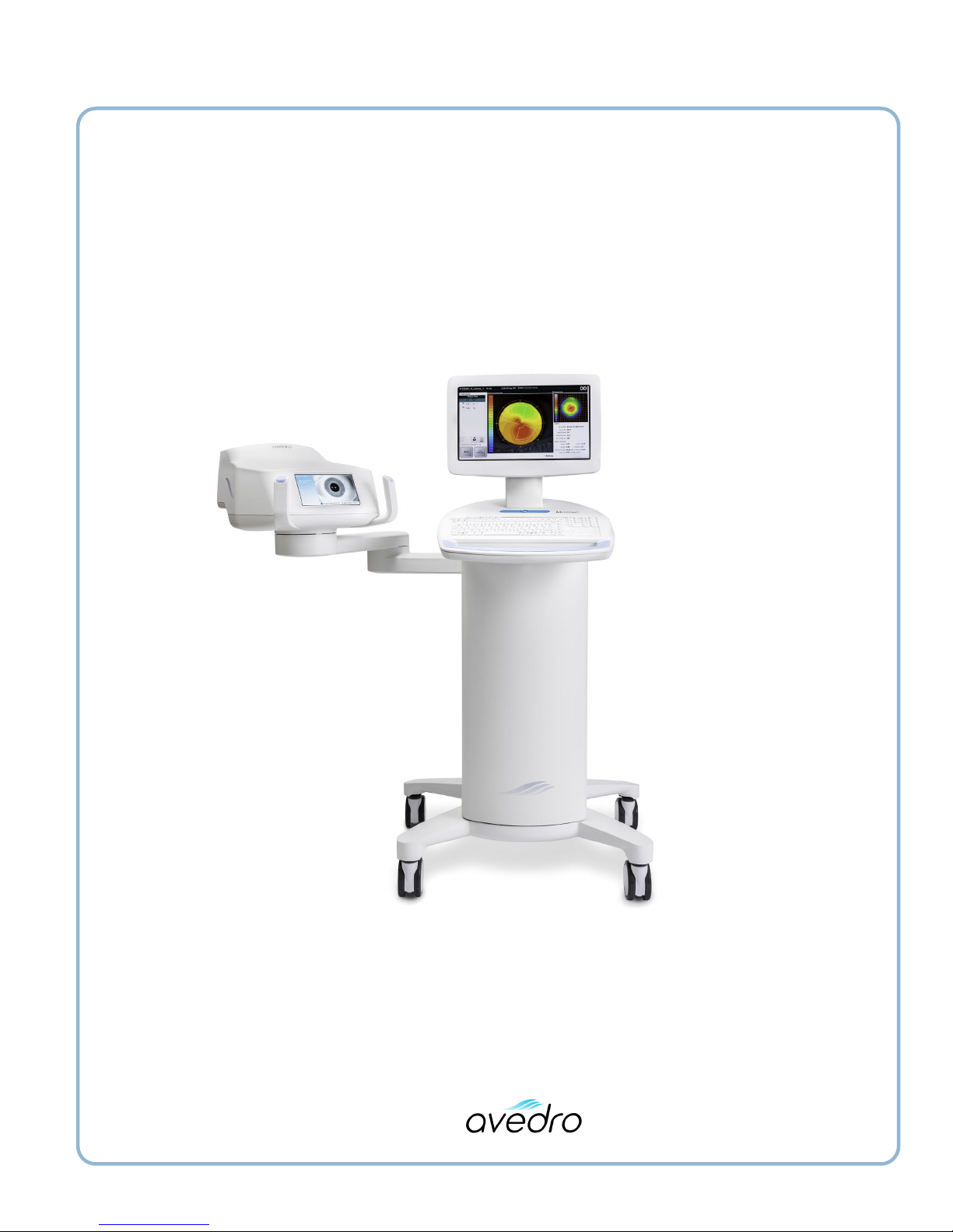
Mosaic Operator’s Manual Rev F
ML-00023
 Loading...