

Page 1

Owner’s Operating Manual
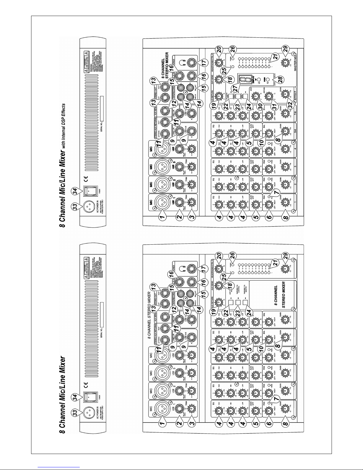
6/8 Channel Mic/Line Mixer
with Internal DSP Effects
PM-6/PM-8
Please read before using this equipment
Page 2

2
Page 3
3
Page 4

4
MONO INPUT CHANNEL
1. MIC INPUT:
Each mono input channel offers a balanced microphone input via the
XLR connector and also features a switchable +48 V phantom power
supply for condenser microphones. The XLR jack is configured for: Pin1
= ground, Pin2 = positive (+), Pin3 = negative (-).
2). LINE IN:
The Line input is designed to accept balanced or unbalanced line level
signals such as those from keyboards, drum machines, or samplers.
There is enough gain available on the line input to accept even lower
level signals, such as those from an unbalanced microphone or guitar
output. If a balanced signal is to be connected to the line input, then a
1/4" TRS (stereo) phone plug should be wired for: Tip = positive (+), Ring
= negative (-), Sleeve = ground.
Note: Only either the MIC or the Line input of a given channel can be
connected at one time. Never connect both simultaneously to the same
channel.
3). TRIM CONTROL:
The TRIM Control adjusts the input sensitivity (channel gain) of the MIC
and line inputs on the mono input channels. This control can be adjusted
to accommodate input signals from a wide variety of sources, from the
high outputs from keyboards or drum machines to the small signal
outputs of microphones. This wide range eliminates the need for
MIC/Line switching. The best balance of S/N and dynamic range will be
achieved if you adjust the TRIM Control on each channel separately so
that the Peak Indicator LED (7) for that channel lights occasionally.
Note: This control should always be turned fully counterclockwise
whenever you connect or disconnect a signal source to one of the inputs.
4). EQUALIZER CONTROLS:
All mono input channels are fitted with three-band EQ. The upper (HIGH)
and lower (LOW) shelving controls have their frequencies fixed at 12 kHz
and 80 Hz respectively. The mid range control has a peaking response,
with Q fixed at 2 octaves, frequency at 2.5 KHz. All three bands have up
to 15 dB of cut and boost, with a center detent for "off".
5). AUX/EFF SEND CONTROL:
The AUX/EFF controls are mono and post-EQ and post-fader and the
signal level sent to the AUX/EFFECTS bus will be affected by the
channel fader setting. The AUX configurations is ideal for almost all
monitoring purpose: for example, for a separate stage monitor mix in live
performances or a studio room monitor in recording applications, such as
for a headphone cue system. The EFF controls the adjustment of level
sent by each channel to the internal DSP (Digital Sound Processor).
6). PAN CONTROL:
The Channel Pan positions the output of the channel in the stereo field of
the Master Mix. Its constant-power design ensures there are no level
discrepancies whether a signal is hard-panned, center-stage, or
somewhere in-between.
7). PEAK LED INDICATOR:
The Peak LED illuminates when a channel is going into overload. It
detects the peak level after the EQ and will light at 3 dB before clipping to
warn that the signal is approaching overload. You do not want the Peak
LED to light except very intermittently during a take or a mix. If it does
light persistently, reduce input gain with the TRIM Control (3).
Page 5

5
8). CHANNEL GAIN CONTROL:
The Channel Gain Controls determine the output signal level to the
Master Mix bus. There is no PFL function on the mixer. In order to
audition any single channel for proper gain, you can turn off the gain
control of all the other channels (fully counterclockwise), and set both the
auditioned channel and Master Mix control (29) to unity gain (0 dB).
The LED Output Meter (21) should read around 0 dB.
STEREO INPUT CHANNEL
4). EQUALIZER CONTROLS:
The stereo channel EQ’s operate in the same manner as those in the
mono channels. The left and right signals will be affected equally. A
stereo equalizer is generally preferable anyhow to using two mono
equalizers when equalizing a stereo signal as it avoids possible
discrepancies between the left and right settings.
5). AUX/EFF SEND CONTROL:
These are the same as for the mono channels. Note that a mono sum is
taken from the stereo input.
8). CHANNEL GAIN CONTROL:
The channel gain controls determine the output signal level to the Master
Mix bus. There is no PFL function on the mixer. In order to audition any
single channel for proper gain, you can turn off the gain control of all the
other channels (fully counterclockwise), and set both the auditioned
channel and Master Mix control (29) to unity gain (0 dB). The LED
Output Meter (21) should read around 0 dB.
9). LINE IN:
Each stereo channel has two balanced line level inputs on 1/4” TRS jacks
for left and right channels, Tip = positive (+), Ring = negative (-), Sleeve =
ground. If only the connector marked “L” (left) is used, the channel
operates in mono. The stereo channels are designed to handle typical
line level signals. The input signals to these jacks can be either balanced
or unbalanced.
10). BAL CONTROL:
For a mono input to the L (MONO) input the function of the control is the
same as the PAN controls (6) of the mono channels. However, when a
channel is run in stereo, this control functions as a Balance control,
determining the relative Balance of the left and right channel signals
being sent to the left and right Master Mix buses. For example, with the
Balance control turned fully clockwise, only the right portion of the
channel’s stereo signal will be routed to the Master Mix.
Page 6

6
MASTER SECTION
11). STEREO AUX RETURNS (LEFT/MONO, RIGHT):
The Aux Return jacks are the mono or stereo returns for Aux Send. If you connect a signal to the
Left/Mono Return jack only, the Aux Return will operate in mono and the signal will be routed
to the Aux Return Control (19) and then mixed into the left and right Master Mix Stereo Outputs (13).
The separate left and right return jacks are provided for use with stereo signals such as those from the
output of a stereo effects processor. The left and right return signals will be routed to the Aux Return
level control (19) and mixed into the left and right Stereo Out (13), while maintaining stereo separation.
12). AUX SEND:
The Aux Send jack is the output for the signal sent from the channel AUX/EFF controls (5) and by the
AUX SEND controls (18) control. They are 1/4" unbalanced phone jacks wired: Tip = positive (+),
Sleeve = ground. Aux Send is post-fader. These signals can be sent to the input of an effects processor,
multi-track recorder, or used for any other line-level auxiliary purpose.
13). STEREO OUTPUTS:
Use these jacks to connect to an external power amplifier if extra output power for a larger P.A. system
is required.
The Stereo Outputs are Left (L) and Right (R) unbalanced 1/4" phone jacks, wired: Tip = positive (+),
Sleeve = ground.
14). TAPE INPUTS:
These jacks will accept the signal from an external device with a stereo output, such as a cassette
recorder.
15). REC OUTPUTS:
The REC Outputs also provide an output of the Master Mix. These outputs are RCA jacks, and designed
primarily for inputs to tape recorders, etc.
16). L-R Control Room Outputs:
The L-R Control Room Outputs can be connected to an amp to power stereo control room (or other)
monitor speakers and are 1/4" unbalanced phone jacks, wired: Tip = positive (+), Sleeve = ground.
17). Phones Output:
The Phones Output will feed headphones and is a 1/4" TRS jack, wired: tip = left signal, ring = right
signal, sleeve = ground.
Page 7

7
18). AUX SEND:
This is a master control that adjusts the output signal level at the AUX SEND (12) jack.
19). AUX RETURN Control:
The left and right return signals will be routed to the Aux Return level control and mixed into the left and
right Stereo Out (13), while maintaining stereo separation.
20). PHONES/CONTROL ROOM CONTROL:
The mixer allows you to monitor the Master Mix. The signal level is adjusted with the Phones/Control
Room control and routed to both the Control Room (16) and Headphones (17) outputs.
21). LED OUTPUT METER:
The 10-stage LED Output Meter displays the Master Mix output level.
22) PHANTOM POWER ON/OFF SWITCH
When using condenser MICs, +48VDC can be switched globally on or off to the XLR MIC inputs for all
mono channels. When this switch is in the “ON” position, The Phantom Power On LED Indicator (25)
will light, and +48VDC will be provided between pins 2 and 3 on all the mono MIC input XLR connectors.
If you don’t need phantom power, be sure to turn this switch to the “OFF” position.
Note: It is safe to connect balanced dynamic MICs or line level devices even if this switch is on, but
connecting unbalanced devices or devices whose transformers are center-grounded will cause hum or
malfunctions. Shorting the +48VDC can also damage your mixer. Also, mute the Monitor/PA speakers
when turning the phantom power on or off.
23). TAPE/REC TO CONTROL ROOM SWITCH:
Use the Tape/Rec to Control Room switch to route signals from the Tape Input (14) to the
Phones/Control Room control (20).
Page 8

8
24). TAPE/REC TO MASTER SWITCH:
Use the Tape/Rec to Master switch to route signals from the Tape Input (14) to the Master Mix Gain
Control (29).
25) PHANTOM POWER LED
The red “+48V” LED lights up when the phantom power is turned on.
26). POWER ON LED INDICATOR:
The red LED indicates that the console is powered on.
DIGITAL EFFECT SECTION (optional)
27). EFFECTS DISPLAY:
Press either Echo Effect Select Buttons to scroll in either direction through the 16 presets. The numeric
Effects Display will indicate which of the 16 effect presets has been selected.
28). ECHO EFFECT SELECT BUTTONS:
The built-in DSP (Digital Sound Processor) offers 16 different preset level and echo intervals selectable
by the Echo Effect Select UP/DOWN buttons. The DSP processes the signal on the EFFECTS bus,
which is the sum of the mono and stereo channel inputs controlled by the EFF control (5).
29). MASTER MIX GAIN CONTROL:
The output level routed to the Stereo Outputs and REC Outputs is determined ultimately by the setting of
the Master Mix Gain Control.
30). EFFECT SEND:
The EFFECT SEND control adjusts the level of the signal on the EFFECTS bus fed to the DSP.
31). EFFECT (ECHO) RETURN:
The EFFECT (ECHO) RETURN control adjusts the number of repeats of the echo effect selected with
the UP/DOWN buttons (28).
32). EFFECT GAIN:
The EFFECTS GAIN fader controls the signal level sent to the Master Mix busses.
REAR PANEL
33). AC POWER IN SOCKET:
Connect the enclosed power supply to the 3-pin mains connector on the rear of the console. Use the
adapter supplied to connect the console to the mains.
34). MAIN POWER SWITCH:
This switches the mixer ON or OFF.
Note: Be sure to switch on the power to your mixer before switching on the amplification
system.
Page 9

9
CONNECTIONS
You will need a lot of cables for different purposes – see the following figures to make sure have got the
right ones. Unbalanced equipment may be connected to balanced input/outputs. Either use mono 1/4”
jacks or connect ring and sleeve of TRS jacks.
Caution:
Never use unbalanced XLR connectors (PIN 1 and 3 connected) on the MIC input connectors when using the
phantom power supply.
Page 10

10
SPECIFICATIONS
1. INPUT SECTION
Input Connector Input Impedance Nominal Level Max Level
MONO CH MIC XLR >1.3K ohms +2 dBm +14 dBm
MONO CH LINE 1/4” TRS >10K ohms +4 dBm +22 dBm
STEREO CH LIN E
1/4” TRS >10K ohms +4 dBm +22 dBm
TAPE IN RCA PIN JACKS >10K ohms +2 dBm +22 dBm
AUX RETURNS 1/4” TRS >10K ohms +4 dBm +22 dBm
2. OUTPUT SECTION
Output Connector Input Impedance Nominal Level Max Level
STEREO OUT L/R 1/4” TRS 120 ohms +4~-6 dBm +22 dBm
AUX SENDS 1/4” TRS 120 ohms +4~-6 dBm +20 dBm
CTRL R OUT 1/4” TRS 120 ohms +4~-6 dBm +22 dBm
REC OUT RCA PIN JACKS 1K ohms +4~-6 dBm +22 dBm
PHONES 1/4” TRS 100 ohms -------------- 40mW * 2
3. FREQUENCY RESPONSE
ANY INPUT TO
ANY OUTPUT .................. 20 Hz to 20 KHz =/- 3dB @ 0 dBm
4. TOTAL HARMONIC DISTORTION
ANY INPUT TO
ANY OUTPUT ............ 0.02%, 20 Hz-20 KHz @ 1Khz, 0 dBm
5. INPUT CHANNEL EQUALIZATION
High shelving ................... 12 KHz, +/- 15 dB, Q fixed at 2 oct.
Mid bell ............................ 2.5 KHz, +/- 15 dB, Q fixed at 1 oct.
Low shelving ....................... 80 Hz, +/- 15 dB, Q fixed at 2 oct.
6. GAIN CONTROL RANGE
Input channel trim control .. Stop to stop- Mic +10 dB~+60 dB
, Line +10 dB~+40 dB
Channel/Master/Effect Faders ........................... -∞?to +15 dB
Aux Send/Aux Master Send .............................. Off to +15 dB
Aux Return ........................................................ Off to +20 dB
Channel and Master Effect Sends .................... Off to +15 dB
7. CROSSTALK @ 1KH
ADJACENT CHANNEL INPUTS ..................... -78 dB~-68 dB
INPUT TO OUTPUT ........................................ -78 dB~-68 dB
8. HUM AND NOISE
20 Hz-20 KHz, Rs=150 ohms, input TRIM @ 0 dB, input
sensitivity at –60 dB
EQUIVALENT INPUT NOISE
-129 dBm
RESIDUAL OUTPUT NOISE
< 90 dBm
9. VU METERS
10-segment LED X 2
10. PHANTOM POWER
+48 VDC, globally selected
11. POWER REQUIREMENTS
Voltage selectable, 120VAC/60Hz or 230VAC/50Hz
12. POWER CONSUMPTION
25W
13. DIMENSIONS AND WEIGHT/ (PSU not
included)
6 CH ……..... 253 x 236 x 55mm, 2.45 Kg/ (1.72 Kg)
8 CH ………. 253 x 290 x 55mm, 2.73 Kg/ (2 Kg)
The specifications above are correct at the time of printing of this manual. For improvement purposes, all specifications for this
unit, including design and apperance, are subject to change without prior notice.
CAUTION:
The apparatus shall not be exposed to dripping or splashing and that no objects filled with liquids, such as vases,
shall be placed on the apparatus.
54INA12.032907
Page 11

11
BLOCK DIAGRAM
Page 12

12
 Loading...