

Page 1
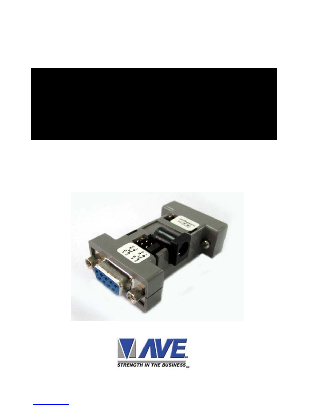
Opto 232
Adapter
Applications and
Operation Manual
Page 2

Opto 232 Adapter
RS-232 Bi-Directional Optically Isolated Adapter
• Introduction
The Opto232 is designed specially for the VSI-Pro but will
work with any RS-232C device. It basically separates the
ground signal from the transmitting device to the receiving
device by optical LED devices.
The specific application is to optically isolate the RS-232 signals and ground from cash registers to the VSI-Pro and the
CCTV system. Many CCTV systems use many different power
sources to power the cameras which are normally very far
from the recording system. This can create power ground
loops which make the ground signa l of the C CT V system be at
a higher voltage other than zero or ground. When this high
voltage ground is connected to the cash register ground all
kinds of problems can arise and can d amage either the CCTV
system or the cash register or both. Therefore isolating the
ground signal via the Opto232 prevents this problem.
• Function
The Opto232 requires a power source for the VSI-Pro side
and another power source from the cash registers side. Since
the VSI-Pro can power external devices via the DTR (Pin4)
and DSR (Pin6) of its DB9F connector an external power
source for the VSI-Pro side is not required and no external
power supply connector is supplied. Therefore if you use another device other than the VSI-Pro you must make sure one
of these pins can supply a minimum of 10 VDC or you must
wire a user supplied external supply to one of these pins.
Page 2
Page 3

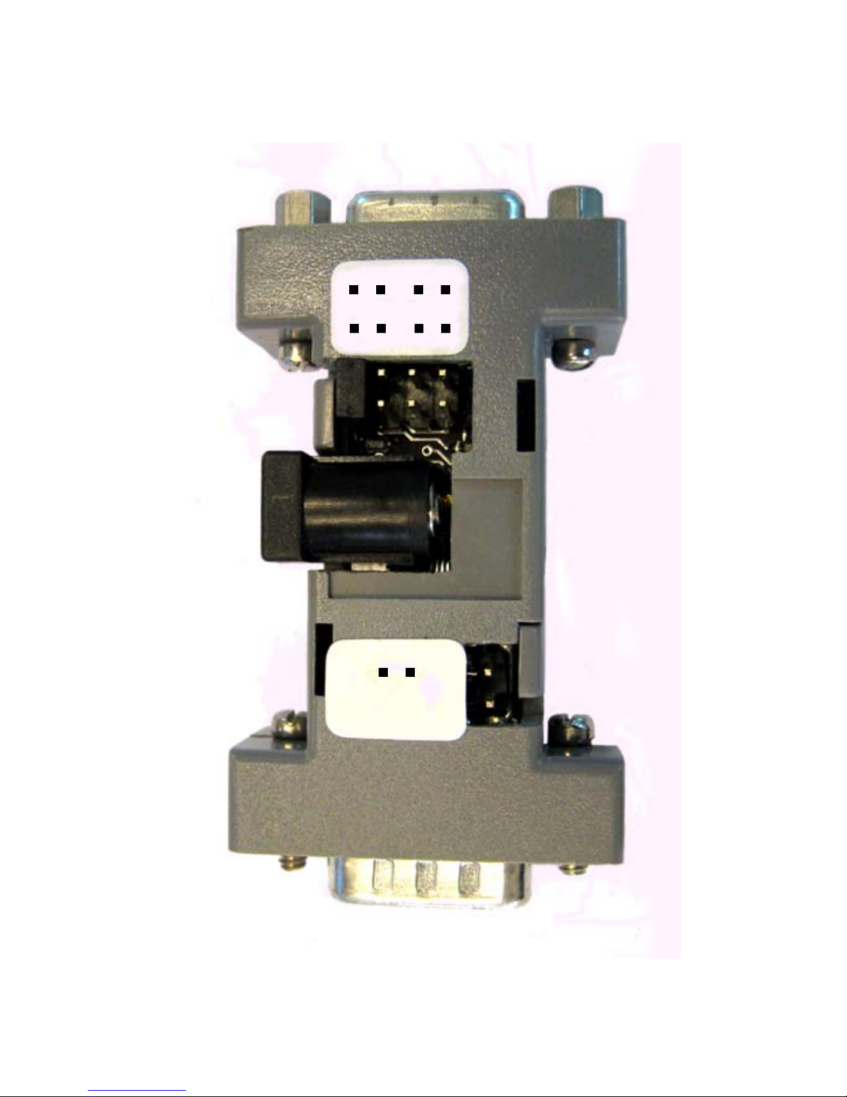
The cash register side has an external power supply connector to use a standard 2.1 x 5.5 mm DC Coax power connector
and unregulated 12VDC should be used. However the Opto232 has jumpers to select using DTR (Pin4) and DSR (Pin6)
to power to the Opto232 if the cash register has this ability.
However, if the cash register is just using its TXD signal to
send data to the VSI-Pro no power supply or power connection is required. This power source is only required if data from
the VSI-Pro is to be sent to the cash register and the cash
register receives the data on its RXD.
• Shielding
The metal shield of a DB9 connector is normall y connected to
the shield of the cable to eliminate RFI and E MI interference in
the RS-232 signal. In the Opto232 the metal shield of each
DB9 connector is not connected to anything so a true isolation
between input and output. Therefore the shield of any cable to
the Opto232 must be connected to the shield of the sending or
receiving device since no con nection is made to or through the
Opto232.
• VSI-Pro Connection
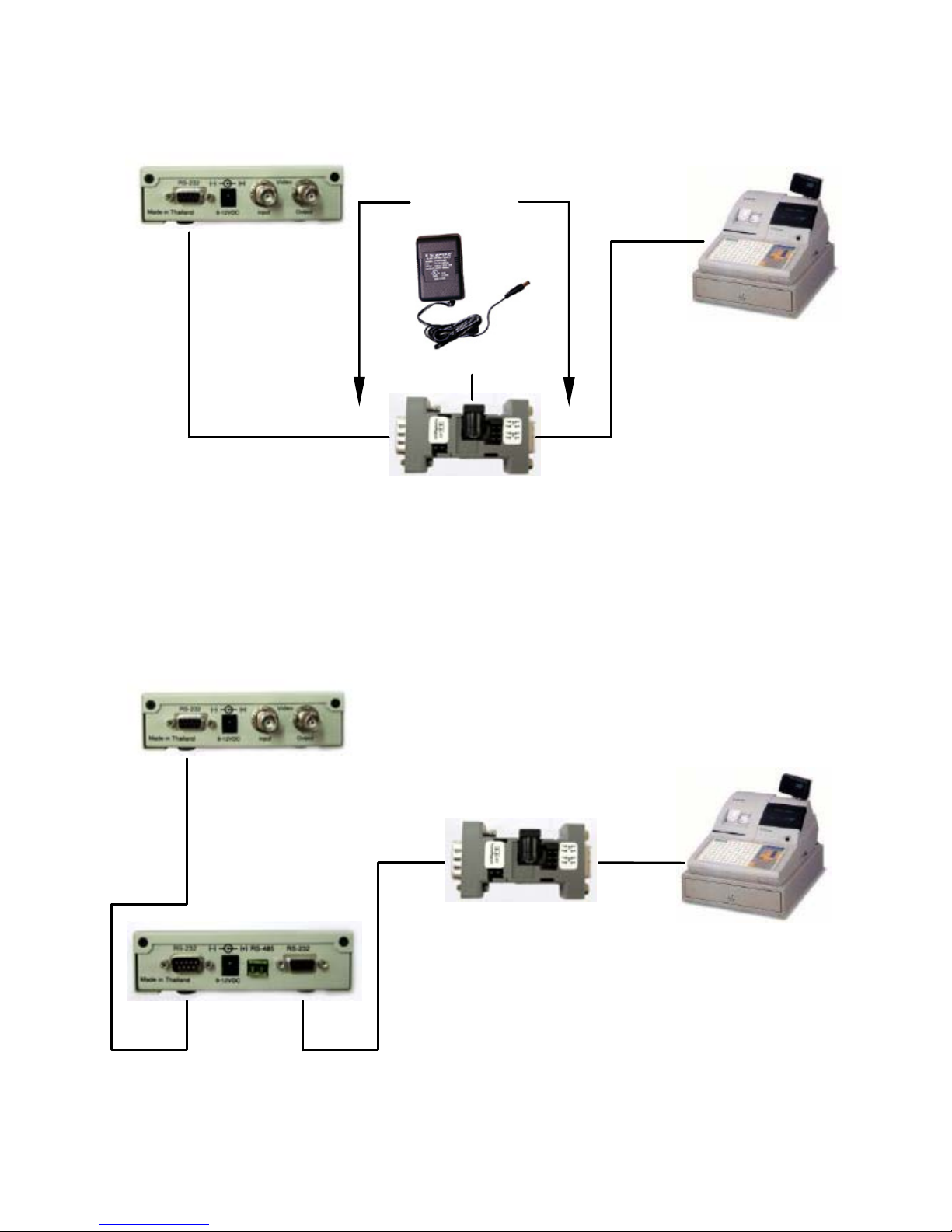
In most cases the Opto232 can plug in line with all the standard cash register cables from AVE. It also can plug directly to
the DB9F connector on the rear of the VSI-Pro. A standard
CR-802 cable which is a DB9M to DB9F 9 conductor extension cable can also work between the VSI-Pro and the Opto232 or between the Opto232 and the register.
Page 3
Page 4

Page 4
• DVR Connection
Since the DVR ground is normally part of the CCT V ground it
should be connected directly to the ground of the VSI-Pro. If
you are using the TXD output of the VSI-Pro to the DVR, Re gcom, Networker or Vnetworker then you should use an AVE
“Multifunction Cable Adapter” directly on the rear of the VSIPro and then use the Opto232 after that connection to the
cash register. The Multifunction cable will wire the TXD signal
with the VSI-Pro ground directly to the DVR before the Opto232 and isolate the ground from the DVR from the cash r egister. If you wish to isolate the ground of the VSI-Pro from the
DVR then you should use another Opto232 or that purpose. It
is not recommended to connect the DVR ground to the cash
register ground but in many cases for properl y installed CCTV
systems this will be okay.
• Other Connections
Jumpers are provided in the Opto232 to defeat standard RS232C Hardware handshaking functions without special cable
wiring. It allows you to short RTS and CTS together and/or
DTR and DSR together via convenient jumpers.
Page 5

Page 5
• Connector Pin Out and Assignments
DB9M to VSI-Pro Side
1 – N/C
2 – TXD
3 – RXD
4 – DTR Connected to power the Opto232
5 – GND
6 – DSR Connected to power the Opto232
7 – RTS N/C
8 – CTS JP1 ON = Connected to power of the Opto232
OFF = N/C
9 – N/C
DB9F from Cash Register Side
1 – N/C
2 – RXD
3 – TXD
4 – DTR JP1 1-2 ON = Connected to power the Opto232
1-2 OFF = Not Connected to power the Opto232
JP2 3-4 ON = Short DTR (4) to DSR (6)
5 – GND
6 – DSR JP1 3-4 ON = Connected to power the Opto232
3-4 OFF = Not Connected to power the Opto232
7 – RTS JP2 1-2 ON = Short RTS (7) to CTS (8)
8 – CTS JP2 1-2 OFF = No Short
9 – N/C
Page 6
Page 6
Opto 232 Adapter
JP1
2 4
1 3
JP4
2 4
1 3
JP3
2 4
Hydra Regcom
2.1mm X 5.5mm
DC Coax Jack
Page 7

Page 7
DVR
Vnetworker
Networker / Regcom
CR-802 or
Plug Direct
Multi - Function Cable
M
Cash Register
F
Use Standard
Emulate / Tap Cable
M F
VSI-Pro
CR-802 or
Plug Direct
USB
RS232 Adapter
VSI-Pro
Opto 232
Opto 232
VSI-Pro Opto 232 with DVR, Networking, Regcom
VSI-Pro Opto 232 & USB232
Page 8
PC
Page 8
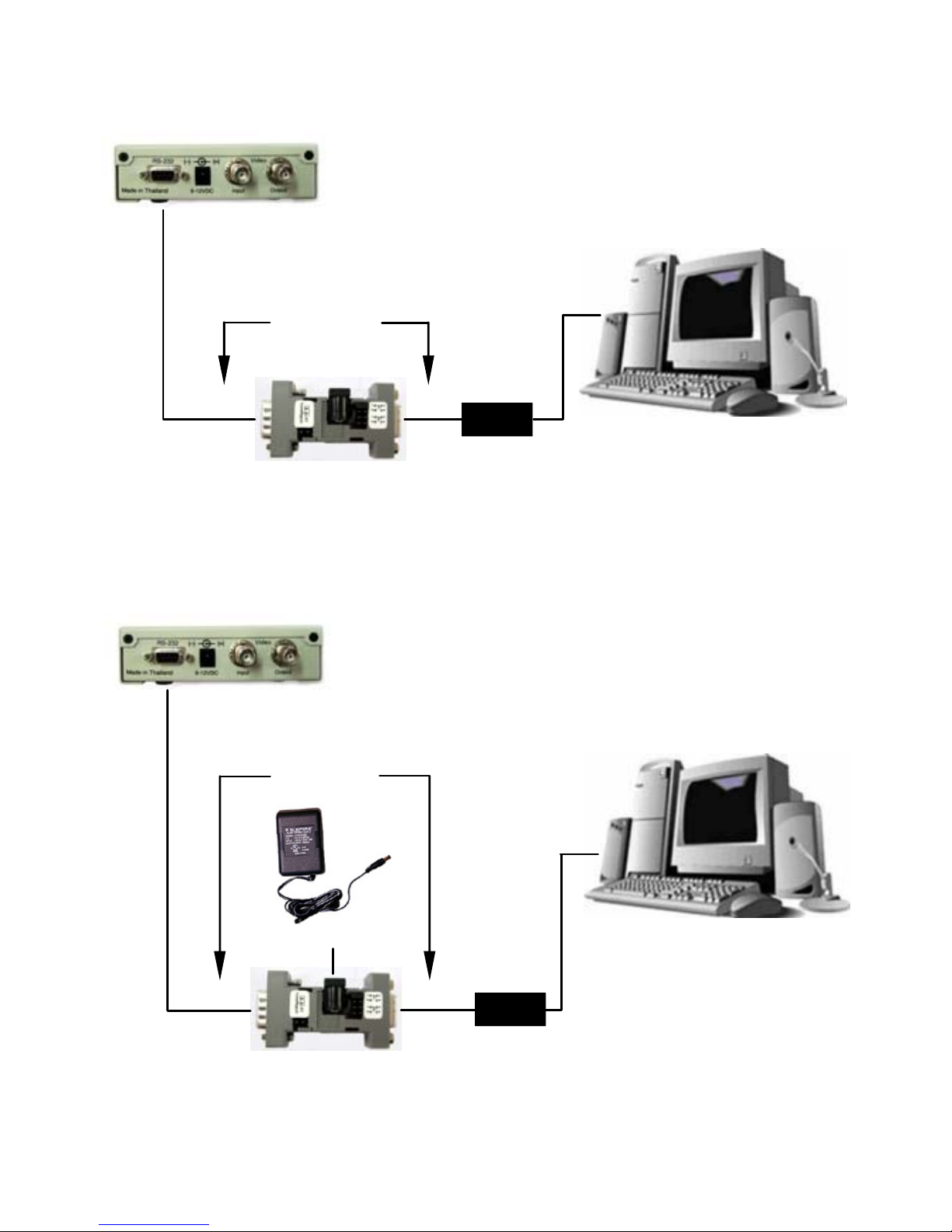
VSI-Pro to PC Opto 232 Powered by PC
VSI-Pro to PC External Power
PC
PIN 7 - 8
PIN 4 - 6
& Powered
PIN 7 - 8
PIN 4 - 6
& Powered
VSI-Pro
VSI-Pro
M
F
Opto 232
Gender
Changer
Gender Changer
CR-802 or
Plug Direct
CR-802 or
Plug Direct
M
F
Power Supply
Opto 232
Page 9
Page 9
Cash Register
Use Standard
Emulate/ Tap Cable
VSI-Pro with Vnetworker & Opto 232
CR-802 or
Plug Direct
CR-802
M
F
Vnetworker
VSI-Pro
Opto 232
Use Standard
Emulate / Tap Cable
VSI-Pro Opto 232
Cash Register
Emulate / Protocol
VSI-Pro
CR-802 or
Plug Direct
M
F
Power Supply
Opto 232
Optional
Page 10

Notes
_____________________________________
_____________________________________
_____________________________________
_____________________________________
_____________________________________
_____________________________________
_____________________________________
_____________________________________
_____________________________________
_____________________________________
_____________________________________
_____________________________________
_____________________________________
_____________________________________
_____________________________________
_____________________________________
_____________________________________
_____________________________________
_____________________________________
_____________________________________
_____________________________________
_____________________________________
Page 10
Page 11

Notes
Page 11
_____________________________________
_____________________________________
_____________________________________
_____________________________________
_____________________________________
_____________________________________
_____________________________________
_____________________________________
_____________________________________
_____________________________________
_____________________________________
_____________________________________
_____________________________________
_____________________________________
_____________________________________
_____________________________________
_____________________________________
_____________________________________
_____________________________________
_____________________________________
_____________________________________
_____________________________________
Page 12

March 2008
ASIA
AVE (Thailand) Company Limited
147 Soi Onnut 44 (Sampheenong Villa), Sukhumvit Ro ad.,
Suanluang, Suanluang, Bangkok 10250, Thailand.
Tel : 02-331-3964/ 02-331- 9285/ 02-742-0221
Fax : 02-331-9365
Email: [email protected]
Website : www.avethailand.com
NORTH AMERICA
AVE USA
2000 West Governors Circle, Suite E
Houston, Texas 77092
Tel: 281-443-2300 Fax: 281- 443-8915
Email: [email protected]
Website: www.americanvideoequipment.com
UK and Western Europe
AVE Multiview
Unit 1C, The Potteries,
Woodgreen Road, Waltham Abbe y
Essex, EN9 3SA, UK
Tel: 440-870-770-9323
Fax: 440-870-770-9363
Email: [email protected]
Website: www.multiview.net
Ireland
AVE Euro
Email: [email protected]
Website: www.multiview.net
 Loading...